Loading ...
Loading ...
Loading ...
100868 - LOAD MANAGEMENT MODULE- ALL aXis CONTROLLER MODELS
®
11
7. Replace the cover.
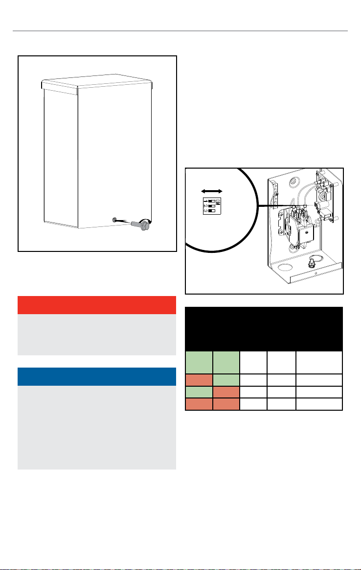
Connecting the LMM to the ATS
DANGER
Electrical shock hazard. May cause injury or
death. Disconnect all sources of supply before
servicing.
NOTICE
The control loads will be shut off one at a time
starting with the lowest priority until Power
Management determines the generator can
handle the house load. If a controlled load
is being turned off before a lower priority
load, rearrange the order of the loads until
satisfactory performance is achieve.
Setting DIP Switches
The DIP Switches set parameters of the controller.
There are only 3 DIP switches on the LMM. These
are the designated “ON” or “OFF” position settings
for the DIP switches;
DIP Switches 1-3 on LMM circuit board are used to
communicate with the ATS circuit board and create
a hierarchy.
Switches 1-2 are used to set hierarchy. Switch 3 is
reserved for future use.
OFF ON
LMM
DIP
Switch
1
LMM
DIP
Switch
2
LMM
DIP
Switch
3
Priority
Corresponding
ATS DIP Switch
On On
Not
Used
Highest DIP Switch 4
Off On DIP Switch 3
On Off DIP Switch 2
Off Off Lowest DIP Switch 1
DIP Switches 1-4 on ATS circuit board control lock-
out of LMM during standby generator operation. DIP
Switch 4 corresponds to the highest priority load and
DIP switch 1 corresponds to the lowest priority load.
Set individually to OFF if the desired load should not
function during generator operation. Set to ON the
attached load will be controlled by load management
protocol.
Loading ...
Loading ...
Loading ...