Operator's Manual
®
15"
4 Speed
Metal/Wood Cutting
BAND SAW
Model No.
351.224401
CAUTION: Read and follow
all Safety Rules and Operating
Instructions before First Use
of this Product.
Sears, Roebuck and Co., Hoffman Estates, IL 60179 U.S.A.
www.sears.com/craftsman
24967.00 Draft (10/22/06)

Warranty.................................... 2
SafetyRules............................... 2-3
Unpacking.................................. 3
Assembly................................. 3-5
Installation................................. 5-6
Operation................................. 6-9
Maintenance................................ 10
Troubleshooting............................. 11
PartsIllustrationsandLists.................. 12-21
EspaSol................................. 22-31
ONE-YEAR FULL WARRANTY ON
CRAFTSMAN PROFESSIONAL TOOL
If this Craftsman tool fails due to a defect in material or
workmanship within one year from the date of purchase,
call 1-800-4-MY-HOME® TO ARRANGE FOR FREE
REPAIR (or replacement if repair proves impossible).
This warranty does not include expendable parts, such
as lamps, batteries, bits or blades.
If this tool is ever used for commercial or rental purposes,
this warranty will apply for only 90 days from the date of
purchase.
This warranty gives you specific legal rights and you may
also have other rights which vary from state to state.
Sears, Roebuck and Co., Hoffman Estates, IL 60179
WARNING: For your own safety, read all of the
instructions and precautions before operating tool.
CAUTION: Always follow proper operating procedures
as defined in this manual -- even if you are familiar
with use of this or similar tools. Remember that being
careless for even a fraction of a second can result in
severe personal injury.
BE PREPARED FOR JOB
• Wear proper apparel. Do not wear loose clothing,
gloves, neckties, rings, bracelets or other jewelry
which may get caught in moving parts of machine.
• Wear protective hair covering to contain long hair.
• Wear safety shoes with non-slip soles.
• Wear safety glasses complying with United States
ANSI Z87.1. Everyday glasses have only impact
resistant lenses. They are NOT safety glasses.
• Wear face mask or dust mask if operation is dusty.
• Be alert and think clearly. Never operate power tools
when tired, intoxicated or when taking medications
that cause drowsiness.
© Sears, Roebuck and Co,
2
PREPARE WORK AREA FOR JOB
• Keep work area clean. Cluttered work areas invite
accidents.
. Do not use power
Do not use power
not expose power
tools in dangerous environments.
tools in damp or wet locations. Do
tools to rain.
. Work area should be properly lighted.
. Proper electrical receptacle should be available for
tool. Three-prong plug should be plugged directly
into properly grounded, three-prong receptacle.
. Extension cords should have a grounding prong and
the three wires of the extension cord should be of
the correct gauge.
. Keep visitors at a safe distance from work area.
. Keep children out of workplace. Make workshop
childproof. Use padlocks, master switches or remove
switch keys to prevent any unintentional use of
power tools.
TOOL SHOULD BE MAINTAINED
° Always unplug tool prior to inspection.
• Consult manual for specific maintaining and adjust-
ing procedures.
• Keep tool lubricated and clean for safest operation.
• Remove adjusting tools. Form habit of checking to
see that adjusting tools are removed before switch-
ing machine on.
• Keep all parts in working order. Check to determine
that the guard or other parts will operate properly
and perform their intended function.
• Check for damaged parts. Check for alignment of
moving parts, binding, breakage, mounting and any
other condition that may affect a tool's operation.
• A guard or other part that is damaged should be
properly repaired or replaced. Do not perform
makeshift repairs. (Use parts list provided to order
replacement parts.)
KNOW HOW TO USE TOOL
° Use right tool for job. Do not force tool or attachment
to do a job for which it was not designed.
. Disconnect tool when changing blade.
. Avoid accidental start-up. Make sure that the tool is
in the "off" position before plugging in.
. Do not force tool. It will work most efficiently at the
rate for which it was designed.
. Keep hands away from moving parts and cutting
surfaces.
. Never leave tool running unattended. Turn the power
off and do not leave tool until it comes to a complete
stop.
. Do not overreach. Keep proper footing and balance.
o Never stand on tool. Serious injury could occur if tool
is tipped or if blade is unintentionally contacted.
. Know your tool. Learn the tool's operation, applica-
tion and specific limitations.

• Use recommended accessories (refer to page 15).
Use of improper accessories may cause risk of
injury to persons.
• Handle workpiece correctly. Protect hands from pos-
sible injury.
° Turn machine off if it jams. Blade jams when it digs
too deeply into workpiece. (Motor force keeps it
stuck in the work.) Do not remove summed or cut off
pieces until the saw is turned off, unplugged and the
blade has stopped.
WARNING: The operation of any power tool can result in
foreign objects being thrown into the eyes, which can
result in severe eye damage. Always wear safety goggles
complying with United States ANSI Z87.1 (shown on
package) before commencing power tool operation.
Safety goggles are available through your Sears catalog.
Check for shipping damage. If damage has occurred, a
claim must be filed with carrier. Check for complete-
ness. Immediately report missing parts to dealer.
The band saw comes assembled as one unit. Additional
parts which need to be fastened to the saw should be
located and accounted for before assembling:
A Table Assembly
B Rip Fence with Knob
C Miter Gauge Assembly
D V-belt
E Metal Cutting Blade, 14TPI
F Wood Cutting Blade, 6 TPI
G Dust Chute
Hardware Bag (Part No. 24958.00) includes:
H Trunnion Rod with Acorn Nut
I Knob with Internal Threads
J Handle
K Front Trunnion
° 5/16"Flat Washer (3)
. 8-1.25 x 20mm Socket Head Bolt (2)
° 8mm Lock Washer (2)
° 8/lOmm Open End Wrench (1)
. 12/14mm Open End Wrench (1)
. 2.5, 3mm and 5mm Hex Wrench (1 each)
. 5-0.8 X 8mm Pan Head Screw (4)
IMPORTANT: Table is coated with a protectant. To
ensure proper fit and operation, remove coating.
Coating is easily removed with mild solvents, such as
mineral spirits, and a soft cloth. Avoid getting solution
on paint or any of the rubber or plastic parts. Solvents
may deteriorate these finishes. Use soap and water on
paint, plastic or rubber components. After cleaning,
cover all exposed surfaces with a light coating of oil.
Paste wax is recommended for table top.
I
Figure 1 - Unpacking
WARNING: Never use highly volatile solvents. Non
flammable solvents are recommended to avoid possible
fire hazard.
Refer to Figure 2, 6-11.
CAUTION: Do not attempt assembly if parts are miss-
ing. Use operator's manual to order replacement parts.
INSTALL METAL CUTTING BLADE
Refer to Figures 2, 8 and 9.
. Make sure blade teeth are pointing down towards
table. Turn blade inside out if necessary.
° Rotate handwheel (Figure 8, Key No. 23) counter-
clockwise to move blade wheels towards each other.
° Loosen handle (Figure 9, Key No. 30). Rotate hand-
wheel (Figure 9, Key No. 22) to lower upper blade
guide assembly as low as possible.
° Loosen three screws (Figure 9, Key No. 5). Remove
blade guards (Figure 9, Key Nos. 4 and 38).
° Slip blade over upper and lower blade wheels, and
center blade on blade wheels. Slide blade in
between blade guides.
. Rotate handwheel clockwise to tension blade.
° Replace blade guards and secure in place by tight-
ening screws. Raise upper blade guide assembly.
° Position clutch handle (Figure 8, Key No. 62) to
"Metal". See Figure 2.
NOTE: The blade must be tensioned and tracked, and
the blade guides must be adjusted before operation of
the saw. Refer to "Tensioning Blade", "Tracking Blade"
and "Blade Guides" in the OPERATION section, page 7.
INSTALL WOOD CUTTING BLADE
Refer to figures 2, 7, 8, 9 and 11.
° The V-belt (Figure. 11, Key No. 25) must be installed
first when using the saw to cut wood.
3

. Loosen knob (Figure 7, Key No. 14). Place V-belt on
motor and drive pulleys (Figure 8, Key Nos. 46 and
50).
° Tension V-belt by pushing down on motor mount
plate and tightening knob. Belt is properly tensioned
when light pressure applied to midpoint of the belt
produces about 1/2" deflection.
. Make sure blade teeth are pointing down towards
table. Turn blade inside out if necessary.
o Rotate handwheel (Figure 8, Key No. 23) counter-
clockwise to move blade wheels towards each other.
° Loosen handle (Figure 9, Key No. 30). Rotate hand-
wheel (Figure 9, Key No. 22) to lower upper blade
guide assembly as low as possible.
° Loosen three screws (Figure 9, Key No. 5). Remove
blade guards (Figure 9, Key Nos. 4 and 38).
° Slip blade over upper and lower blade wheels, and
center blade on blade wheels. Slide blade in
between blade guides.
° Replace blade guards and secure in place by tight-
ening screws. Raise upper blade guide assembly.
. Rotate handwheel clockwise to tension blade.
° Position clutch handle (Figure 8, Key No. 62) to
"Wood". See Figure 2.
Wood
Metal f
Figure 2 - Clutch Handle Position
NOTE: The blade must be tensioned and tracked, and
the blade guides must be adjusted before operation of
the saw. Refer to "Tensioning Blade", "Tracking Blade"
and "Blade Guides" in the OPERATION section, page 7.
ATTACH DUST CHUTE
Refer to Figure 7.
° Position dust chute (Key No. 29) against saw frame.
. Secure in position using four pan head screws
(Key No. 3).
ATTACH TABLE
Refer to Figure 10.
. Table (Key No. 1) is attached to frame with two cast
iron trunnions.
o Remove table stud (Key No. 16)
. Finger tighten one socket head bolt with washer (Key
Nos. 3 and 4) on left side of front trunnion (Key No.
2) into table.
. Bring table to frame by inserting back of blade into
slot. Position table with back trunnion (Key No. 5) on
guide posts which are welded to frame.
. Position front trunnion so it rides on guide post.
Attach handle with flat washer (Key Nos. 13 and 11)
to secure back trunnion.
o Insert trunnion rod with acorn nut and flat washer
(Key Nos. 10 and 11) through other guide post and
attach the internally threaded knob with flat washer
(Key Nos. 12 and 11) to the trunnion rod.
. Mount second bolt with washer on front trunnion.
Position front trunnion flat against bottom of table
and tighten internally threaded knob to secure.
° Tighten socket head bolts (Key No. 3) to secure trun-
nions to table. Install table stud.
SET HORIZONTAL STOP
Refer to Figure 10.
• When table is attached to frame, a bolt (Key No. 14)
is used for a horizontal stop.
• Loosen trunnion knob and set table at 90° to blade
using a square.
• Secure position of table with knob.
• Adjust bolt to contact bottom edge of table.
° Lock bolt in position with hex nut (Key No. 15).
ATTACH RIP FENCE
Refer to Figure 10.
• Rip fence (Key No. 19) rides in the slot of table (Key
No. 1).
• Slide rip fence into slot.
• Hold rip fence to table and fasten by threading knob
(Key No. 20) into rip fence.
• Rip fence can be repositioned by loosening knob.
ALIGN TABLE
Refer to Figure 10.
• The table must be aligned properly so that the blade
is at a right angle to the table and that the rip fence
is aligned with the blade.
• Lock the table in the horizontal position. Mount the
rip fence on the table. Slide the rip fence next to, but
not touching, the blade. Lock the rip fence.
• Check that the blade is aligned parallel with the rip
fence. If the blade and fence are not parallel, loosen
handle and knob (Key Nos. 12 and 13) on the trun-
nions (Key Nos. 2 and 5). Adjust the table position so
that the blade and rip fence are parallel. Secure the
table position by tightening handle and knob.
• After assembly, the table has to be aligned in order
to have the blade running through the center of the
slot in the table insert.
° To move table sideways, loosen bolts (Key No. 3) on
the trunnions (Key Nos. 2 and 5). Move table to left
or right until blade runs through the center of slot.
Tighten bolts and make sure that table stays in posi-
tion while bolts are being tightened.
4
INSTALL V-BELT (METAL CUTTING)
Refer to Figures 6, 7 and 11.
. Band saw uses a step-pulley drive system to provide
a selection of blade speeds for metal cutting.
o Loosen knob (Figure 7, Key No. 14). Place V-belt
(Figure 11, Key No. 25) on idler pulley and motor
pulley (Figure 11, Key Nos. 23 and 26) with V-belt in
desired location on pulleys. (See Figure 6, Blade
Speeds, page 8.)
. Do not over tighten V-belts. Excessive tension on V-
belt will reduce life of belt. Belt is properly tensioned
when light pressure applied to midpoint of the belt
produces about V2"deflection.
o Tension V-belt by pushing down on motor mount
plate and tightening hex head bolt and hex nut.
MOUNT SAW TO FLOOR
• If saw is not properly positioned on a flat surface, it
may develop excessive vibration.
• Mount to a flat, level surface through holes on top of
base.
Refer to Figures 3, 4 and 5.
MOTOR
The 115/230 Volt AC motor has the following
specifications:
Horsepower (Continuous Duty) .................. 1
Voltage ............................... 115/230
Amps .................................... 14/7
Hertz ..................................... 60
Phase .................................. Single
RPM .................................... 1720
POWER SOURCE
The motor is designed for operation on the voltage and
frequency specified. Normal loads will be handled safe-
ly on voltages not more than 10% above or below the
specified voltage.
Running the unit on voltages which are not within the
range may cause overheating and motor burn-out.
Heavy loads require that the voltage at motor terminals
be no less than the voltage specified. Power supply to
the motor is controlled by a double pole locking rocker
switch. Remove the key to prevent unauthorized use.
GROUNDING INSTRUCTIONS
WARNING: Improper connection of equipment
grounding conductor can result in the risk of electrical
shock. Equipment should be grounded while in use to
protect operator from electrical shock.
Check with a qualified electrician if grounding instruc-
tions are not understood or if in doubt as to whether the
tool is properly grounded.
This tool is equipped with an approved 3 conductor
cord rated at 300V and a three prong grounding type
plug for your protection against shock hazards.
Grounding plug should be plugged directly into a prop-
erly installed and grounded 3-prong grounding-type
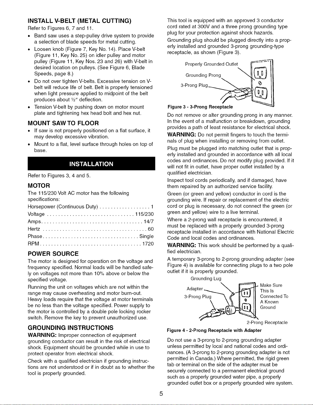
receptacle, as shown (Figure 3).
Properly Grounded Outlet ---'_=---::
Grounding Prong "_ ___
3-Prong Plug
Figure 3 - 3-Prong Receptacle
Do not remove or alter grounding prong in any manner.
In the event of a malfunction or breakdown, grounding
provides a path of least resistance for electrical shock.
WARNING: Do not permit fingers to touch the termi-
nals of plug when installing or removing from outlet.
Plug must be plugged into matching outlet that is prop-
erly installed and grounded in accordance with all local
codes and ordinances. Do not modify plug provided. If it
will not fit in outlet, have proper outlet installed by a
qualified electrician.
Inspect tool cords periodically, and if damaged, have
them repaired by an authorized service facility.
Green (or green and yellow) conductor in cord is the
grounding wire. If repair or replacement of the electric
cord or plug is necessary, do not connect the green (or
green and yellow) wire to a live terminal.
Where a 2-prong wall receptacle is encountered, it
must be replaced with a properly grounded 3-prong
receptacle installed in accordance with National Electric
Code and local codes and ordinances.
WARNING: This work should be performed by a quali-
fied electrician.
A temporary 3-prong to 2-prong grounding adapter (see
Figure 4) is available for connecting plugs to a two pole
outlet if it is properly grounded.
Grounding Lug
Make Sure
Ada This Is
3-Prong Plug Connected To
A Known
Ground
5
2-Prong Receptacle
Figure 4 - 2-Prong Receptacle with Adapter
Do not use a 3-prong to 2-prong grounding adapter
unless permitted by local and national codes and ordi-
nances. (A 3-prong to 2-prong grounding adapter is not
permitted in Canada.) Where permitted, the rigid green
tab or terminal on the side of the adapter must be
securely connected to a permanent electrical ground
such as a properly grounded water pipe, a properly
grounded outlet box or a properly grounded wire system.

Manycoverplatescrews,waterpipesandoutletboxes
arenotproperlygrounded.Toensureproperground,
groundingmeansmustbetestedbyaqualifiedelectrician.
• Seewiringdiagram(Figure5)forwiringinstructions,
single-phaseoperation.
EXTENSION CORDS
• The use of any extension cord will cause some drop
in voltage and loss of power.
• Wires of the extension cord must be of sufficient size
to carry the current and maintain adequate voltage.
• Use the table to determine the minimum wire size
(A.W.G.) extension cord.
• Use only 3-wire extension cords having 3-prong
grounding type plugs and 3-pole receptacles which
accept the tool plug.
• If the extension cord is worn, cut or damaged in any
way, replace it immediately.
EXTENSION CORD LENGTH
Wire Size A.W.G.
Up to 50 ft. (115 volts) ........................ 12
Up to 50 ft. (230 volts) ........................ 18
NOTE: Using extension cords over 50 ft. long is not
recommended.
ELECTRICAL CONNECTIONS
WARNING: All electrical connections must be per-
formed by a qualified electrician. Make sure unit is off
and disconnected from power source while motor is
mounted, connected, reconnected or anytime wiring is
inspected.
• Band saw motor can be wired for 115 or 230 volts,
single-phase operations.
Switch Circuit Breaker
i
Yellow Red #6
White
L1
L1
Black White #5
115V
Black Yellow
230 V
L2
#5 #6 Red
1_2
Figure 5 - Wiring Diagram
Refer to Figures 6 - 11.
The Craftsman 15" Metal/Wood Cutting Band Saw is for
cutting ferrous and non-ferrous metals and also hard
and soft woods. The band saw features a unitized frame
of welded steel construction and a solid cast iron work
surface to ensure durability. Table tilts 45° and has a
miter gauge and precision machined rip fence for per-
forming many different operations. Fifteen inch bal-
anced cast iron wheels with ball bearings and rubber
treads accommodate blade widths up to 3/4". A conve-
nient tensioning and tracking mechanism makes blade
changing quick and easy. Rip fence and miter gauge
can be stored on the saw when not in use.
SPECIFICATIONS
Depth of throat ............................ 14%"
Maximum depth of cut ....................... 10"
Table size ............................. 15 x 15"
Table tilt .............................. -5 to 45°
Wheel diameter ............................ 15"
Blade length .............................. 114"
Blade range ........................... 112-115"
Blade width ............................. 3/_6to 3_
Blade speeds .......... 80, 150, 200 and 3,000 FPM
Overall dimensions .................. 68 x 27 x 22"
Shipping weight ......................... 215 Ibs
Dust collection port ........................... 4"
CAUTION: Always observe the following safety
precautions:
• Make sure that blade guides and thrust bearings are
positioned and adjusted correctly to prevent side-
ways and rearward movement of the blade. Adjust
upper guide to just clear workpiece.
• Check to make sure blade is tensioned and tracking
properly. Do not over tension the blade in order to
prevent premature blade wear and breakage. Avoid
under tensioning to eliminate back and forth, side to
side blade movement as it cuts.
• Use proper blade and speed for the cutting operation.
• After turning saw on, allow blade to come to full
speed before attempting any cutting operation.
• Support workpiece properly and use a smooth
steady feed to guide work through the cut. Use push
sticks or push blocks when required.
• Keep hands away and out of line with moving parts.
• Always wear eye protection.
WARNING: Some dust created by power sanding,
sawing, grinding, drilling and other construction activi-
ties contains chemicals known to cause cancer, birth
defects or other reproductive harm.
6

Some examples of these chemicals are:
. Lead from lead-based paints.
. Crystalline silica from bricks and cement and other
masonry products.
. Arsenic and chromium from chemically-treated lumber.
Your risk from these exposures vary, depending on how
often you do this type of work. To reduce your exposure
to these chemicals: work in a well ventilated area and
work with approved safety equipment. Always wear
OSHNNIOSH approved, properly fitting face mask or
respirator when using such tools.
REMOVING BLADE
Refer to Figures 8, 9 and 10.
WARNING: Disconnect band saw from power source
when changing or adjusting blades. Wear leather gloves
when handling band saw blades. Never wear gloves
when operating saw.
° Loosen three screws (Figure 9, Key No. 5). Remove
blade guards (Figure 9, Key Nos. 4 and 38). Loosen
hex nut (Figure 8, Key No. 30) and rotate handwheel
(Figure 8, Key No. 23) to release blade tension. Be
careful; blade may spring from saw when tension is
released. Remove table stud (Figure 10, Key No. 16),
take out the released blade and replace with another
blade.
INSTALLING BLADE
° Although many of the adjustments may not be altered
when blade is removed, every adjustment should be
checked prior to using a newly installed blade.
. Follow safety precautions every time saw is operated.
. Make sure blade teeth are pointing down towards
table. Turn blade inside out if necessary.
. Slip new blade into table slot and over upper and
lower blade wheels and center blade on blade
wheels. Slide blade in between blade guides.
Replace table stud. Replace blade guards after
blade guide adjustment.
. Tension and track blade as described in the following
sections.
TENSIONING BLADE
Refer to Figure 8.
° Tension blade by rotating handwheel (Key No. 23). Be
sure blade guides do not interfere with blade path.
. Tighten blade until it is properly tensioned.
. A properly tensioned blade will ring slightly when back
of blade is plucked (like a string on an instrument).
NOTE: Check tension of new blade. Additional tension
may be required after a few minutes of operation.
TRACKING BLADE
Refer To Figure 8.
° Track blade after it has been tensioned. A change in
blade tension will affect wheel alignment.
. Proper tracking is achieved when drive and idler
wheels are aligned. Knob (Key No. 29) is used to tilt
tracking bar (Key No. 13) and align blade wheels.
° Loosen hex nuts (Key No. 30) which lock tracking
knob (Key No. 29). Turn idler wheel (Key No. 7) by
hand and observe how blade rides on wheels.
. If blade rides away from cabinet, turn knob clockwise
to tilt idler wheel up.
. If blade rides into cabinet, turn tracking knob coun-
terclockwise.
° When blade is tracking properly, lock position by
holding knob and tightening hex nuts (Key No. 30)
against the cabinet.
ALIGNMENT OF DRIVE WHEEL
Refer to Figure 11.
NOTE: Only attempt adjusting drive wheel alignment if
blade cannot be properly tracked with tracking adjust-
ment alone.
. A blade under high tension may also pull drive wheel
out of alignment.
. Adjust alignment of drive wheel using hex head bolts
(Key Nos. 8 and 30).
BLADE GUIDES
NOTE: Adjust blade guides only after blade has been
properly tensioned and tracked.
. Blade guides support blade at sides and rear of
blade, and prevent twisting or deflection.
. Blade guides should not touch blade when no work-
piece is in contact with blade. Adjust guides as
described in following sections.
UPPER BLADE GUIDES
Refer to Figure 9.
° Upper blade guides employ guide pins for side sup-
port and a ball bearing on an adjusting pin at rear.
° Upper guide bracket (Key No. 13) should be posi-
tioned so guide on either side of blade will support
as much of blade width as possible without interfer-
ing with the tooth set.
• Adjust bracket depth by loosening bolts (Key Nos. 9
and 12) and sliding brackets into position. Secure
position of upper guide casting by tightening bolts.
• Loosen set screws (Key No. 15) and adjust guide
pins (Key No. 14) to side of blade. Use a feeler gauge
to check that guide pins are .002" away from blade.
• Lock adjustment by tightening set screws.
• Adjust thrust bearing (Key No. 17) at rear of blade by
loosening set screw (Key No. 15).
• Position thrust bearing .002" away from back of blade.
• Secure position of thrust bearing by tightening set
screw.
• Adjust the height of upper guide casting to clear the
workpiece by W'. Loosen knob (Key No. 30) and
rotate height adjustment knob (Key No. 22) until
upper blade guide bracket clears workpiece by W'.
Tighten knob.
7

LOWER BLADE GUIDES
Refer to Figure 9.
• Lower blade guides employ two guide blocks for side
support. Lower guide bracket is spaced close to table
surface to minimize unsupported length of blade.
• Loosen screw (Key No. 5) and remove blade guard
(Key No. 38).
• Loosen bolt (Key No. 19) to position lower guide
bracket on alignment block (Key No. 31). Adjust
lower guide bracket so guide blocks do not interfere
with blade set. Loosen set screws (Key No. 23) for
guide blocks (Key Nos. 21 and 34) and adjust guide
blocks to .002" from each side of blade.
• Adjust thrust bearing (Key No. 36) at rear of blade by
loosening set screw (Key No. 23). Position thrust
bearing .002" away from back of blade. Secure posi-
tion of thrust bearing by tightening set screw.
• Replace blade guard and secure in position.
BLADE SELECTION
• Blades vary depending on type of material, size of
workpiece and type of cut that is being performed.
• Characteristics which make blades different are
width, thickness and pitch.
BLADE WIDTH
• Width of blade describes distance from tip of a tooth
to back of blade.
• Width of blade will affect rigidity of blade. A wider
blade will wander less and produce a straighter cut.
• Width of blade also limits the smallest radius which can
be cut. A 1A"wide blade can cut about a _/2"radius.
BLADE THICKNESS
• Blade thickness describes the distance between
sides of blade. A thicker blade has more rigidity and
stronger teeth.
• A narrow thick blade would be used to cut curves
while a wide thin blade would be used to make long,
straight cuts.
BLADE PITCH
• Pitch describes number of teeth per inch or tooth
size. A blade with more teeth per inch will produce a
smoother cut.
• The type of material being cut determines number of
teeth which should be in contact with work.
• For soft metals, the proper blade has between 6 to
12 teeth per inch.
• When cutting hard metals, where shocking is more
detrimental, use a blade with 12 to 24 teeth per inch.
• For softwoods, the proper blade has 4 to 8 teeth per
inch.
• For hardwoods, the proper blade has 8 to 12 teeth
per inch.
• There should always be at least three teeth in con-
tact with cut to avoid shocking blade.
• Blade shocking occurs when pitch is too large and
blade tooth encounters too much material. This can
strip teeth from blade.
• Blade manufacturers are prepared to supply informa-
tion about blades for specific applications.
BLADE SPEED
Refer to Figure 6.
• The amount of force with which the blade cuts is
determined by speed.
• High cutting speeds are used on soft materials
where less force is needed and a high rate of materi-
al removal is desired.
• Low cutting speeds are used on hard materials
when more force is required.
• To change blade speed, position V-belt in proper
configuration (see Figure 6). Reposition and tension
V-belt as described in the next section.
80 FPM .................... Steel and Steel Alloys
150 FPM ................... Cast Iron and Bronze
200 FPM ............. Aluminum, Brass and Copper
80 FPM 150 FPM 200 FPM
Figure 6 - Blade Speeds
REPOSITIONING V-BELT (METAL CUTTING)
Refer to Figures 6, 7 and 11.
• Blade speed is determined by the position of the
V-belt on the idler and motor pulleys (Figure 11, Key
Nos. 23 and 26). Blade speed is changed by chang-
ing pulley position of V-belt.
• Be sure to disconnect saw from power and turn saw
OFF before attempting to change blade speed.
• To change blade speed loosen motor mount plate
(Figure 7, Key No. 9) by loosening knob (Figure 7,
Key No. 14). Position V-belt on motor and idler pul-
leys as required. See Figure 6, Blade Speeds, for
recommended pulley and belt settings.
• Tension V-belt by pushing down on motor mount
plate and tightening knob. Belt is properly tensioned
when light pressure applied to midpoint of the belt
produces about W' deflection. Do not over tighten
V-belt.
CHANGING THE SAW OPERATION FROM
METAL TO WOOD CUTTING
Refer to Figures 2, 7, 8 and 11.
• Remove metal cutting blade. See "Removing Blade"
above.
8
• Remove shroud (Figure 11, Key No. 28).
• Loosen knob (Figure 7, Key No. 14). Remove V-belt
from motor and idler pulleys (Figure 11, Key Nos. 23
and 26).
• Place V-belt on motor and drive pulleys (Figure 8,
Key Nos. 46 and 50).
• Tension V-belt by pushing down on motor mount
plate and tightening knob. Belt is properly tensioned
when light pressure applied to midpoint of the belt
produces about W' deflection.
• Change clutch handle from "metal" to "wood". (Refer
to Figure 2)
• Replace shroud.
• Install wood cutting blade. See "Installing Blade",
page 7. Properly tension, track and adjust blade
guides before operation.
CHANGING THE SAW OPERATION FROM
WOOD TO METAL CUTTING
Refer to Figures 2, 7, 8 and 11.
• Remove wood cutting blade. See "Removing Blade"
above.
• Loosen knob (Figure 7, Key No. 14). Remove V-belt
from motor and drive pulleys (Figure 8, Key Nos. 46
and 50).
• Remove shroud (Figure 11, Key No. 28).
• Place V-belt on motor and idler pulleys (Figure 11,
Key Nos. 23 and 26).
• Tension V-belt by pushing down on motor mount
plate and tightening knob. Belt is properly tensioned
when light pressure applied to midpoint of the belt
produces about W' deflection.
• Change clutch handle from "wood" to "metal". (Refer
to Figure 2)
• Replace shroud.
• Install metal cutting blade. See "Installing Blade",
page 7. Properly tension, track and adjust blade
guides before operation.
TYPE OF CUT
• Rip fence guides workpiece to produce straight cuts
on longer pieces.
• Contour cutting is done by guiding workpiece free-
handed to produce curved shapes.
• Beveled cutting can be done by tilting table and
using proper work guide method.
• Regardless of which work guiding method is used, a
workpiece which overhangs table by more than 7"
should be properly supported by support stands.
(See Recommended Accessories, page 15.)
RIP FENCE OPERATION
Refer to Figures 10 and 11.
• Rip fence can be used to guide boards with one
square edge past blade when table is aligned prop-
erly.
• Set rip fence to desired width of cut on inside of
throat. Remember to include the thickness of materi-
al that will be removed by blade.
• Use a square to measure from tip of a tooth to fence.
Lock fence securely with knob (Figure 1O,Key No. 20).
• The portion of material between blade and fence is
considered the workpiece. Material on outside and
behind cut is the scrap material which is being cut
off. Use the right hand to keep work against fence.
• Do not push on scrap portion of the work. This could
pinch or bind blade.
• Avoid passing hands beyond the cut. Use push
sticks or push blocks to finish cuts and pass work-
piece away from blade.
• A storage bracket (Figure 11, Key No. 40) for rip
fence is located on the rear of saw.
CONTOUR SAWING
• When contour sawing, use both hands to keep work-
piece flat against table and guided along desired
path.
• Avoid positioning hands in line with blade. If hands
slip they could contact blade.
• Try to stand to front of the saw and use hands over
the portion of table which is to right of blade and
before cut.
• Cut small corners by sawing around them. Saw to
remove scrap until desired shape is obtained.
BEVEL CUTTING
Refer to Figure 10.
• Perform a bevel operation by tilting table. Loosen
handle and knob (Key Nos. 12 and 13) and tilt table
to desired position.
• Use a square or protractor to set angle and lock
table in position with knob. Use caution when sup-
porting work while bevel cutting. Do not allow work
to hang on blade.
MITER GAUGE
Refer to Figure 10.
• Use miter gauge for securing and holding workpiece
at desired angle to produce angled cuts. Use scale
to adjust gauge to desired angle.
• Never use miter gauge and rip fence at the same
time. The blade might bind in the workpiece.
Operator could be injured and/or workpiece could be
damaged.
• A storage bracket (Key No. 33) for miter gauge is
located on the rear of saw.
BLADE CLEANING BRUSH
Refer to Figure 8.
• Make sure that brush (Key No. 36) is in contact with
blade to properly remove foreign particles from drive
wheel.
9

WARNING: Make certain that unit is disconnected
from power source before attempting to service or
remove any component.
CLEANING
• Keep machine and workshop clean Do not allow
sawdust to accumulate on band saw
• Keep wheels clean Debris on wheels will cause
poor tracking and blade slippage
• Keep mechanisms and threaded or sliding surfaces
clean and free of foreign particles
• Operate band saw with a dust collector to minimize
clean up
LUBRICATION
• The shielded ball bearings are permanently lubricat-
ed and require no further lubrication
• Small amounts of machine oil can be applied to belt
tension mechanisms and threaded or sliding sur-
faces
• Occasionally apply a coat of automobile type wax to
table top to keep it slick and corrosion free
KEEP BAND SAW IN REPAIR
• If power cord is worn or cut in any way, have it
replaced
• Replace V-belt and blade when they are worn
Replace any damaged or missing part
• Use parts list to order parts
10

SYM PTO M
Excessive blade breakage
Premature blade dulling
Crooked cuts
POSSIBLE CAUSE(S)
1.Material not secure on table
2. Incorrect speed or feed
3.Blade too coarse for material
4. Incorrect blade tension
5. Teeth in contact with work before
sawing
6. Blade rubs on wheel flange
7.Misaligned guides
8.Blade too thick for wheel diameter
9.Cracking at weld
1.Blade too coarse
2. Excessive blade speed
3. Inadequate feed pressure
4. Hard spots or scale in or on
material
5. Work hardening of workpiece
6. Blade installed backwards
7. Insufficient blade tension
1.Work not square
2. Rate of feed too great
3.Blade guides not adjusted properly
4. Insufficient blade tension
5. Upper blade guide too far
from workpiece
6. Dull blade
7. Incorrect speed
8.Blade guide assembly loose or
blade thrust bearing loose
CORRECTIVE ACTION
1. Squarely place work on table
2. Check Blade Speed (Figure 6, page 8)
3. Use finer pitch blade
4. Tension blade properly; see "Operation"
5. Place blade in contact with work after saw is
started and has reached full speed
6. Adjust wheel alignment properly
7. Adjust blade guides properly
8. Use thinner blade
9. Replace blade
1. Use finer tooth blade
2. Try lower speed
3. Gently increase pressure
4. Reduce speed; increase rate of feed for
scale and change blades for hard spots
5. Increase rate of feed
6. Remove blade, twist inside out and reinstall
blade
7. Tension blade properly; see "Operation"
1. Use rip fence; adjust tilt of table at 90° to
blade
2. Reduce rate of feed
3. Move both guide blocks within .002" from
blade (use gauge)
4. Tension blade properly; see "Operation"
5. Adjust upper guide to just clear workpiece
by 1A"
6. Replace blade
7. Check Blade Speed; see Figure 6, page 8 for
recommended speeds
8. Tighten blade thrust bearing within .002"
behind blade back
Rough cuts 1.Too much speed or feed 1. Reduce speed or feed
2. Blade too coarse 2. Replace with finer blade
1.Cut is binding blade
2. Blade guides or bearing worn
3.Blade guides or bearings not
adjusted properly
4. Blade guide brackets loose
1.Teeth too coarse for work
2. Rate of feed too great
3.Vibrating workpiece
4. Teeth filling with material
Blade is twisting or unusual
wear on side/back of blade
Teeth ripping from blade
Motor running too hot
1.Blade tension too great
2. Blade too coarse for work
(typical when cutting pipe)
3.Blade too fine for work (typical
when cutting slick or soft material)
4. Excessive dirt and chips
1. Decrease feed pressure
2. Replace
3. Adjust blade guides; see "Operation"
4. Tighten properly
1. Use blade with finer teeth
2. Decrease feed rate
3. Hold workpiece firmly
4. Use blade with coarser teeth
1. Reduce tension on blade
2. Use blade with finer teeth
3. Use blade with coarser teeth
4. Clean thoroughly; vacuum motor and speed
change mechanism
Saw will not start Loose electrical connections Have qualified electrician check electrical
connections
11

Model 351.224401
Figure 7 - Replacement Parts Illustration for Motor
28
29
3
o
25
/
26
23
/
20
I
3
8
/
1
6
24
18
./
12
J
\
17
12

KEY
NO. PART NO.
1 16080. O0
2 03668.01
3 STD863508
4 05156. O0
5 STD840707
6 18970.00
7 18971.00
8 02434.00
9 08294.00
10 08295.00
11 18924.00
12 STD551037
13 08297.00
14 18953. O0
15 08299.00
16 08300. O0
17 STD561210
18 STD835020
19 05188.00
20 01634.00
21 STD852008
22 STD840812
23 02813.00
24 18972.00
25 08685.00
26 08677.00
27 03981.00
28 04287.00
29 24934.00
DESCRIPTION
Switch
Switch Plate
5-0.8 x 8mm Pan Head Screw*
4mm Serrated Washer*
4-O.7mm Hex Nut*
Line Cord
Motor Cord
Strain Relief
Motor Mount Plate
Slide Bracket
3_-16 x 6V2"Carriage Bolt
3_,,Flat Washer*
Spacer
Knob
Pivot Bracket
Clevis Pin
1_x 1" Cotter Pin*
8-1.25 x 20mm Hex Head Bolt*
8-1.25 x 20mm Carriage Bolt
Strain Relief
8mm Lock Washer*
8-1.25mm Hex Nut*
_/_6x _/_x 11/2"Key
Motor
4-0.7 x 15mm Pan Head Screw
Strain Relief Plate
Cord Clamp
Circuit Breaker
Dust Chute
* Standard hardware item available locally.
QTY.
1
1
13
1
1
1
1
2
1
1
1
3
1
1
1
1
1
4
4
1
8
8
2
1
1
2
1
1
1
13

Model 351.224401
Figure 8 - Replacement Parts Illustration for Front
3
\
8
f
6
43
10
1
44
\
6
45
\
8
10
9
35
11
36
15
41
39 7
48
15
34
20
27
6
49
30
57
25
26
15 21
/
%
29
63
60
/
\
59
14

KEY
NO. PART NO.
1 N/A
2 24959.01
3 08303.01
4 03663.00
5 08304.00
6 00964.00
7 24960.00
8 08306.00
9 03838.00
10 STD315235
11 06358.01
12 00341.00
13 03605.01
14 STD835025
15 STD852008
16 03608.00
17 03606.00
18 03609.00
19 STD835070
20 STD851008
21 STD840812
22 08601.00
23 05598.01
24 03610.00
25 STD833016
26 STD851006
27 STD840610
28 03607.00
29 08307.00
30 STD541031
31 08308.00
32 STD851010
33 STD841015
DESCRIPTION QTY.
Frame 1
Upper Cabinet Door 1
Lower Cabinet Door 1
Knob (External Threads) 2
Latch 2
6-1.0 x 6mm Set Screw 9
Idler Wheel 1
Rubber Tread 2
3BMI-40 Retaining Ring 2
6203ZZ Bearing* 2
Idler Shaft 1
3AM1-17 Retaining Ring 1
Tracking Bar 1
8-1.25 x 25mm Hex 1
Head Bolt*
8mm Lock Washer* 12
Tracking Adjustment Bracket 1
Tension Bracket 1
Upper Cabinet Support 2
8-1.25 x 70mm Hex 2
Head Bolt*
8mm Flat Washer* 8
8-1.25mm Hex Nut* 9
Threaded Shaft 1
Handwheel 1
Tension Support 1
6-1.0 x 16mm Hex 8
Head Bolt*
6mm Flat Washer* 16
6-1.0mm Hex Nut* 8
Tension Nut 1
Tracking Knob 1
_6"-18 Hex Nut* 2
10-1.5mm Eye Bolt 1
lOmm Flat Washer* 1
10-1.5mm Hex Nut* 1
* Standard hardware item available locally.
KEY
NO. PART NO.
34 24961.00
35 07904.00
36 20071.00
37 03620.00
38 17741.00
39 01090.00
40 STD851005
41 08439.00
42 00958.00
43 00256.00
44 STD835030
45 STD315545
46 18926.00
47 18927.00
48 STD835020
49 18928.00
50 24962.00
51 24963.00
52 24964.00
53 01822.00
54 18930.00
55 18931.00
56 16985.00
57 STD551031
58 16981.00
59 STD870812
60 20073.00
61 18934.00
62 18933.00
63 18942.00
DESCRIPTION QTY.
Drive Wheel 1
3BMI-42 Retaining Ring 2
Brush 1
Bracket 1
4.8-2.1 x 8mm Thread 2
Forming Screw
5-0.8 x 15mm Pan Head 1
Screw
5mm Flat Washer* 2
17mm Wavy Washer 1
8-1.25 x 8mm Set Screw 1
3AMI-20 Retaining Ring 1
8-1.25 x 30mm Hex 3
Head Bolt*
6004ZZ Bearing* 2
Drive Pulley 1
Drive Clutch 1
8-1.25 x 20mm Hex Head 3
Bolt*
Movable Clutch 1
Motor Pulley 1
Metal Cutting Blade, 14 TPI 1
Wood Cutting Blade, 6 TPI 1
8-1.25 x 20mm Socket 4
Head Bolt
Shift Bar 1
Stud 1
Pillow Block with Bushing 2
5/16"Flat Washer* 1
Collar 2
8-1.25 x 12mm Socket Head 3
Bolt
1_"-12x 13/16Ball Plunger 1
Cam 1
Clutch Handle 1
Knob 1
Recommended Accessories
A Support Stand 9-21417
A 3-Roller Support Stand 9-22265
15
Model 351.224401
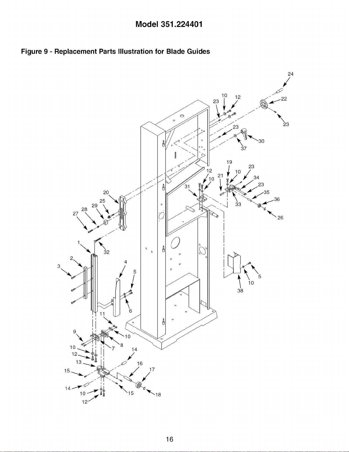
Figure 9 - Replacement Parts Illustration for Blade Guides
3
16
17
,/
18
0
o
o
o
o
lO 12
38
16

KEY
NO. PART NO.
1 24965.00
2 24941.00
3 06045.00
4 24966.00
5 03619.01
6 STD851005
7 08314.00
8 08607.00
9 STD833025
10 STD851006
11 STD840610
12 STD833016
13 08316.00
14 08317.00
15 00958.00
16 08318.00
17 STD315205
18 01434.00
19 STD833012
20 08319.00
21 08298.00
22 24942.00
23 00964.00
24 07305.00
25 08322.00
26 08323.00
27 STD870635
28 09564.00
29 08324.00
30 08352.00
31 06376.00
32 08325.15
33 08353.00
34 08354.00
35 08355.00
36 STD315485
37 STD551031
38 20163.00
DESCRIPTION
Guide Bar
Rack
5-0.8 x 20mm Socket Head Bolt
Upper Blade Guard
Thread Forming Screw
5mm Flat Washer*
Guide Attaching Bracket
Guide Depth Bracket
6-1.0 x 25mm Hex Head Bolt*
6mm Flat Washer*
6-1.0mm Hex Nut*
6-1.0 x 16mm Hex Head Bolt*
Upper Guide Bracket
Guide Pin
8-1.25 x 8mm Set Screw
Bearing Pin
6200ZZ Bearing*
3CM1-10 E-Ring
6-1.0 x 12mm Hex Head Bolt*
Guide Casting
Guide Block
Handwheel
6-1.0 x 6mm Set Screw
Handle
Pinion Shaft Assembly
3CMI-8 E-Ring
6-1.0 x 35mm Socket Head Bolt*
Spring
Positioning Block
Handle
Alignment Block
%-18 x 11_,,Hex Low Head Bolt
Lower Guide Bracket
Guide Block
Bearing pin
608ZZ Bearing*
%" Flat Washer*
Lower Blade Guard
* Standard hardware item available locally.
QTY.
1
1
3
1
3
2
1
1
2
14
2
10
1
2
3
1
1
1
1
1
1
1
6
1
1
1
1
1
1
1
1
1
1
1
1
1
1
1
17

Model 351.224401
Figure 10 - Replacement Parts Illustration for Table
38
13
_) 8 11
10
1
H
U
17
19
/
J
J
16
! /2
20
/
36
,,,_26
ej31
23
29
18

KEY
NO.
1
2
3
4
5
6
7
8
9
10
11
12
13
14
15
16
17
18
19
2O
21
22
23
24
25
26
27
28
29
30
31
32
33
34
35
36
37
38
PART NO.
08326.00
03660.00
STD870820
STD852008
08327.00
08328.00
01286.00
08329.00
STD863508
09574.00
STD551031
03659.00
08330.00
STD835025
STD840812
08331.00
00210.00
06369.00
05351.00
00010.00
08251.00
08250.00
08049.00
01093.00
08256.00
08252.00
STD541010
STD511007
08253.00
08254.00
STD551010
01605.00
05991.00
01883.00
08255.00
08257.00
24943.00
STD833012
DESCRIPTION
Table
Front Trunnion
8-1.25 x 20mm Socket Head Bolt*
8mm Lock Washer*
Back Trunnion
Trunnion Scale
Rivet
Trunnion Indicator
5-0.8 x 8mm Pan Head Screw*
Trunnion Rod with Acorn nut
5/16"Flat Washer*
Knob (Internal Threads)
Handle
8-1.25 x 25mm Hex Head Bolt*
8-1.25 Hex Nut*
Table Stud
Table Insert
3 x lOmm Spring Pin
Rip Fence
Knob (External Threads)
Miter Gauge
Miter Gauge Bar
#10 Fiber Washer
Guide
Indexing Pin
Knob (Internal Threads)
#10-24 Hex Nut*
#10-24 x 3A" Pan Head Screw*
Indicator
Scale
#10 Flat Washer*
#10-24 x 1A"Washer Head Screw
#10-24 x _/2"Flat Head Screw
5-0.8 x 8mm Flat Head Screw
Threaded Pin
Miter Gauge Assembly (Key Nos. 21 - 35)
Bracket
6-1.0 x 12mm Hex Head Bolt*
QTY.
1
1
4
4
1
1
3
1
1
1
3
1
1
1
1
1
1
1
1
1
1
1
1
1
1
1
3
3
1
1
1
1
2
1
1
1
1
2
* Standard hardware item available locally.
19
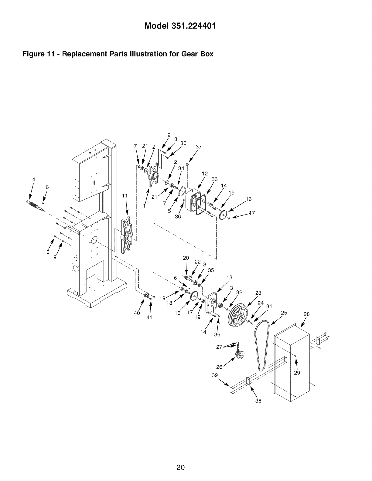
Model 351.224401
Figure 11 - Replacement Parts Illustration for Gear Box
lO
41
20 "',J
3
35
13
3
32
16
19
It
14 36
23
31
25
28
39 -//
38
2O
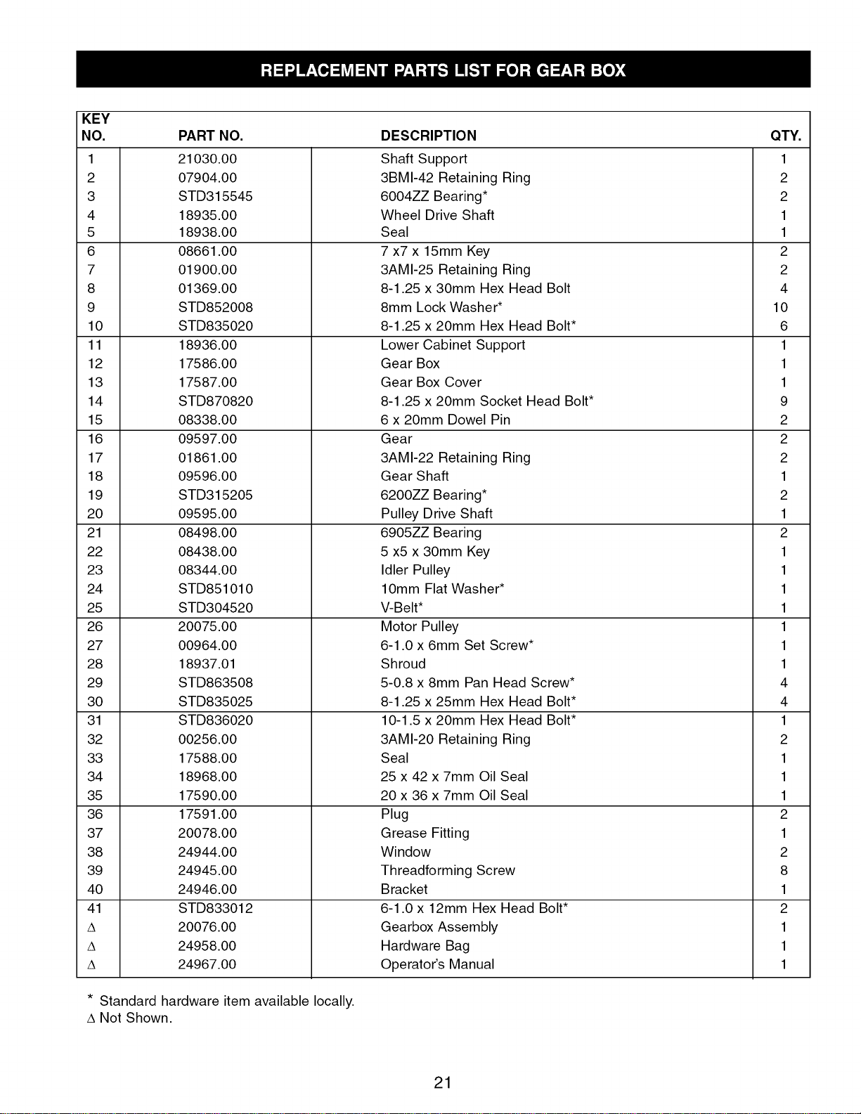
KEY
NO. PART NO.
1 21030.00
2 07904.00
3 STD315545
4 18935.00
5 18938.00
6 08661.00
7 01900.00
8 01369.00
9 STD852008
10 STD835020
11 18936.00
12 17586.00
13 17587.00
14 STD870820
15 08338.00
16 09597.00
17 01861.00
18 09596.00
19 STD315205
20 09595.00
21 08498.00
22 08438.00
23 08344.00
24 STD851010
25 STD304520
26 20075.00
27 00964.00
28 18937.01
29 STD863508
30 STD835025
31 STD836020
32 00256.00
33 17588.00
34 18968.00
35 17590.00
36 17591.00
37 20078.00
38 24944.00
39 24945.00
40 24946.00
41 STD833012
A 20076.00
A 24958.00
A 24967.00
DESCRIPTION
Shaft Support
3BMI-42 Retaining Ring
6004ZZ Bearing*
Wheel Drive Shaft
Seal
7 x7 x 15mm Key
3AMI-25 Retaining Ring
8-1.25 x 30mm Hex Head Bolt
8mm Lock Washer*
8-1.25 x 20mm Hex Head Bolt*
Lower Cabinet Support
Gear Box
Gear Box Cover
8-1.25 x 20mm Socket Head Bolt*
6 x 20mm Dowel Pin
Gear
3AMI-22 Retaining Ring
Gear Shaft
6200ZZ Bearing*
Pulley Drive Shaft
6905ZZ Bearing
5 x5 x 30mm Key
Idler Pulley
lOmm Flat Washer*
V-Belt*
Motor Pulley
6-1.0 x 6mm Set Screw*
Shroud
5-0.8 x 8mm Pan Head Screw*
8-1.25 x 25mm Hex Head Bolt*
10-1.5 x 20mm Hex Head Bolt*
3AMI-20 Retaining Ring
Seal
25 x 42 x 7mm Oil Seal
20 x 36 x 7mm Oil Seal
Plug
Grease Fitting
Window
Threadforming Screw
Bracket
6-1.0 x 12mm Hex Head Bolt*
Gearbox Assembly
Hardware Bag
Operator's Manual
* Standard hardware item available locally.
A Not Shown.
QTY.
1
2
2
1
1
2
2
4
10
6
1
1
1
9
2
2
2
1
2
1
2
1
1
1
1
1
1
1
4
4
1
2
1
1
1
2
1
2
8
1
2
1
1
1
21

Sierra de BANDA CORTADORA,
de Metal y Madera de
4 velocidades, de 15"
Modelo No.
351.224401
PRECAUCION: Lea y siga todas las Reglas
de Seguridad y las Instrucciones de Operaci6n
antes de usar este producto por primera vez.
Ingles ........................................ 2-11
Ilustraci6n y Lista de Partes ...................... 12-21
Garant[a ........................................ 22
Reglas de Seguridad ........................... 22-23
Desempaque .................................... 23
Montaje ...................................... 23-25
Instalaci6n .................................... 25-26
Operaci6n .................................... 26-30
Mantenimiento ................................... 30
Identificaci6n de Problemas ......................... 31
GARANTIA COMPLETA DE UN ANO PARA
HERRAMIENTA PROFESIONAL CRAFTSMAN
Si esta herramienta Craftsman fallara por causa de defectos
en el material o en la mano de obra en un lapso de un aSo a
partir de la fecha de compra, LLAME al 1-800-4-MY-HOME®
PARA SOLICITAR LA REPARACION GRATUITA DEL
PRODUCTO (o su reemplazo si no se puede reparar la
unidad). Esta garant[a no incluye partes fungibles, tales
como lamparas, bater[as, barrenas o cuchillas.
Siesta herramienta se usa alguna vez para fines comerciales
o de alquiler, esta garant[a es valida _nicamente por 90 d[as
a partir de la fecha de compra.
Esta garant[a le otorga derechos legales especfficos y tam-
bi_n puede usted tener otros derechos que var[en de estado
a estado.
Sears, Roebuck and Co., Hoffman Estates, IL 60179
ADVERTENClA: Para su propia seguridad, lea todas
las instrucciones y las precauciones antes de operar la
herramienta.
PRECAUCION: Siempre siga los procedimientos de
operaci6n correctos, tal como se definen en este manual,
aun cuando est_ familiarizado con el uso de _sta o de otras
herramientas similares. Recuerde que descuidarse aunque
s61osea por una fracci6n de segundo puede ocasionarle
graves lesiones.
22
EL OPERADOR DEBE ESTAR PREPARADO
PARA EL TRABAJO
• Use ropa apropiada. No use ropa holgada, guantes, cor-
batas, anillos, pulseras ni otras joyas que puedan atas-
carse en las piezas m6viles de la maquina.
• Use una cubierta protectora para el cabello, para sujetar el
cabello largo.
• Use zapatos de seguridad con suelas antideslizantes.
• Use gafas de seguridad que cumplan con la norma ANSI
Z87.1 de los Estados Unidos. Los anteojos comunes
tienen lentes que s61o son resistentes al impacto. No son
anteojos de seguridad.
• Use una mascara para la cara o una mascara contra el
polvo, si al utilizar la herramienta se produce mucho polvo.
• Est_ alerta y piense claramente. Nunca opere herramien-
tas mecanicas cuando est_ cansado, intoxicado o bajo la
influencia de medicaci6n que produzca somnolencia.
PREPARE EL AREA DE TRABAJO PARA
LA TAREA A REALIZAR
• Mantenga el Area de trabajo limpia. Las Areas de trabajo
desordenadas atraen accidentes.
• No use herramientas mecanicas en ambientes peligrosos. No
use herramientas mecanicas en lugares ht_medos o mojados.
No exponga las herramientas mecanicas a la Iluvia.
• El Area de trabajo debe estar iluminada adecuadamente.
• Debe haber disponible una toma de corriente adecuada
para la herramienta. El enchufe de tres puntas se tiene
que enchufar directamente en un receptaculo de
tres puntas conectado a tierra correctamente.
• Los cordones de extensi6n deben tener una punta de
conexi6n a tierra y los tres alambres del cord6n de
extensi6n deben ser del calibre correcto.
• Mantenga a los visitantes a una distancia prudente del
Area de trabajo.
• Mantenga a los niSos fuera del lugar de trabajo. Haga que
su taller sea a prueba de niSos. Use candados, interrup-
tores maestros y remueva las Ilaves del arrancador para
impedir cualquier uso involuntario de las herramientas
mecanicas.
SE DEBE DAR MANTENIMIENTO A
LA HERRAMIENTA
• Desenchufe siempre la herramienta antes de inspeccionarla.
• Consulte el manual para informarse sobre los proce-
dimientos de mantenimiento y ajuste especfficos.
• Mantenga la herramienta lubricada y limpia de modo que
funcione de la manera mas segura.
• Retire las herramientas de ajuste. Desarrolle el habito de
verificar que hayan sido retiradas las herramientas de
ajuste antes de encender la maquina.
• Mantenga todas las partes listas para funcionar. Revise
el protector u otras piezas para determinar si funcionan
correctamente y hacen el trabajo que deben hacer.
• Revise que no haya partes daSadas. Verifique el ali-
neamiento de las partes m6viles, si hay atascamiento,
roturas y montaje o cualquier otra condici6n que pudiera
afectar el funcionamiento de la herramienta.
• Si hay una protecci6n o cualquier otra parte da_ada, _stas
deberan repararse correctamente o ser reemplazadas. No
haga reparaciones provisionales (valgase de la lista de
piezas incluida para solicitar piezas de reemplazo).

EL OPERADOR DEBE SABER COMO USAR
LA HERRAMIENTA
• Use la herramienta correcta para cada trabajo. No fuerce
la herramienta o el accesorio ni los use para una tarea
para la que no fueron diseSados.
• Cuando cambie la hoja, desconecte la herramienta.
• Evite que la herramienta se encienda por accidente.
Cerci6rese de que la herramienta est_ en la posici6n "off"
(apagado) antes de enchufarla.
• No fuerce la herramienta. Funcionar& en la forma m&s eft-
ciente a la velocidad para la cu&l se dise56.
• Mantenga las manos alejadas de las partes movibles y de
las superficies cortadoras.
• Nunca deje desatendida una herramienta en funcio-
namiento. Descon_ctela y no abandone el lugar hasta
que se haya detenido por completo.
• No trate de alcanzar demasiado lejos. Mant_ngase firme
y equilibrado.
• Nunca se pare sobre la herramienta. Se pueden producir
lesiones graves si la herramienta se vuelca o hace contac-
to con la cuchilla sin intenci6n.
• Conozca su herramienta. Aprenda a manejar la herramien-
ta, su aplicaci6n y limitaciones especfficas.
• Use los accesorios recomendados (consulte la p&gina 15).
Si se usan accesorios incorrectos, puede sufrir lesiones o
lesionar a alguien.
• Maneje la pieza de trabajo en forma correcta. Prot_jase
las manos de posibles lesiones.
• Apague la m&quina si se atasca. La hoja se atasca si se
introduce muy profundamente en la pieza de trabajo (la
fuerza del motor la mantiene trabada en la pieza de traba-
jo). No quite las piezas atascadas o cortadas hasta que se
haya apagado y desconectado la sierra y la hoja se haya
detenido.
ADVERTENCIA: La operaci6n de toda herramienta mec&ni-
ca puede hacer que salgan arrojados objetos extraSos hacia
los ojos y les causen graves heridas. Siempre use gafas de
seguridad que cumplan con los requisitos de la norma esta-
dounidense ANSI Z87.1 (se indica en el paquete) antes de
comenzar a usar la herramienta mec&nica. Puede obtener
gafas de seguridad a trav_s de su cat&logo de Sears.
Verifique que no hayan ocurrido daSos durante el envio. Si
hay daSos, se deber& presentar un reclamo a la compaSia
de transporte. Verifique que est_ completa. Avise inmediata-
mente al distribuidor si faltan partes.
La sierra de banda viene armada como una unidad. Ser&
necesario Iocalizar y ver que no falten las partes adicionales
que deben montarse en la sierra, antes de instalarlas:
A Conjunto de la mesa
B Reborde para serrar a Io largo con manilla
C Conjunto de la guia de ingletes
D Correa V
E Hoja de cortar metal, 14TPI
F Hoja de cortar madera, 6 TPI
G Canal para polvo
Bolsa de herramientas (No. de Parte 24958.00) incluye:
H Varilla del mu_6n con tuerca ciega
I Manilla con roscas internas
23
J Manija
K Mu_6n delantero
• Arandela plana, 5/,,, (3)
• Pernos de cabeza hueca, 8-1.25 x 20 mm (2)
• Arandela de seguridad, 8 mm (2)
• Llave de extremo abierto, 8/10 mm (1)
• Llave de extremo abierto, 12/14mm (1)
• Llaves hexagonales, 2.5 mm, 3 mm y 5 mm (1 de cada una)
• Tornillos de cabeza de placa, 5-0,8 x 8 mm (4)
IMPORTANTE: La mesa viene revestida con un protector.
Para garantizar un ajuste y un funcionamiento correctos,
retire dicho revestimiento. 12stese puede eliminar f&cilmente
mediante solventes suaves, tales como esencias minerales, y
un paso suave. Evite dejar caer esta soluci6n en la pintura o
en cualquier parte de goma o pl&stico. Los solventes pueden
deteriorar estos acabados. Use agua y jab6n en la pintura y
en los componentes de pl&stico o goma. Despu_s de limpiar-
la, cubra todas las superficies expuestas con una capa ligera
de aceite. Se recomienda el uso de cera en pasta para la
parte superior de la mesa.
B _,,/C
Figura 1 - Desempaque
ADVERTENCIA: Nunca use solventes muy vol&tiles. Se
recomienda utilizar solventes no inflamables para evitar posi-
bles incendios.
Consulte las Figuras 2 y 6-11.
PRECAUClON: No intente hacer el montaje si hay partes
que faltan. V&lgase del manual de operador para solicitar
partes de repuesto.
INSTALACION DE LA HOJA DE CORTAR METAL
Consulte las Figuras 2, 8 y 9.
• AsegOrese de que los dientes de la hoja est_n seSalando
hacia abajo, hacia la mesa. D_ vuelta a la hoja de adentro
hacia afuera si es necesario.
• Gire el volante (Figura 8, Clave No. 23) en sentido con-
trario alas manecillas del reloj para mover las ruedas de
la hoja una hacia la otra.
• Suelteelmango(Figura9,ClaveNo.30).Gireelvolante
(Figura9,ClaveNo.22)paradescenderelconjuntodela
gufasuperiordelahojatanbajocomoseaposible.
• Sueltelostrestornillos(Figura9,ClaveNo.5).Retirelas
protecci6nesdelacuchilla(Figura9,ClaveNo.4).
• Deslicelahojasobrelasruedassuperioreinferiordelahoja
yc6ntrelaenlasruedas.Deslicelahojaentresusgufas.
• Gireelvolanteensentidohorarioparatensionarlahoja.
• Vuelvaacolocarlasprotecci6nesdelacuchillay
aseg_relaensuposici6napretandolostornillos.Eleve
elconjuntodelagufasuperiordelahoja.
• Lleveelmanguitodeembrague(Figura8,ClaveNo.62)a
laposici6n"Metal".VealaFigura2.
AVlSO:Lahojadebeestartensayalineada,ylasgufasdela
hojadebenajustarseantesdeponerenfuncionamientolasie-
rra.Consulte"Tensi6ndelahoja","Alineaci6ndelahoja"y
"Gufasdelahoja"enlasecci6nOPERACION,paginas27y28.
INSTALACION DE LA HOJA DE CORTAR MADERA
Consulte las Figuras 2, 7, 8, 9 y 11.
• La correa V (Figura 11, Clave No. 25) se debe instalar
primero cuando se use la sierra para cortar madera.
• Suelte la manilla (Figura 7, Clave No. 14). Ponga la correa
V en la polea del motor y la polea impulsora (Figura 8,
Claves No. 46 y 50).
• Tense la correa V empujando hacia abajo la placa de
montaje del motor y apretando la manilla. La correa tiene
la tensi6n correcta si cuando se aplica una presi6n liviana
en su punto medic se desvia alrededor de 1/2".
• Aseg_rese de que los dientes de la hoja est6n seSalando
hacia abajo, hacia la mesa. D6 vuelta a la hoja de adentro
hacia afuera si es necesario.
• Gire el volante (Figura 8, Clave No. 23) en sentido con-
trario alas manecillas del reloj para mover las ruedas de
la hoja una hacia la otra.
• Suelte el mango (Figura 9, Clave No. 30). Gire el volante
(Figura 9, Clave No. 22) para descender el conjunto de la
gufa superior de la hoja tan bajo como sea posible.
• Suelte los tres tornillos (Figura 9, Clave No. 5). Retire las
protecci6nes de la cuchilla (Figura 9, Claves No. 4 y 38).
• Deslice la hoja sobre las ruedas superior e inferior de la hoja
y c6ntrela en las ruedas. Deslice la hoja entre sus gufas.
• Vuelva a colocar las protecci6nes de la cuchilla y
aseg_rela en su posici6n apretando los tornillos. Eleve el
conjunto de la gufa superior de la hoja.
• Gire el volante en sentido horario para tensionar la hoja.
• Lleve el manguito de embrague (Figura 8, Clave No. 62) a
la posici6n "Wood" (madera). Vea la Figura 2.
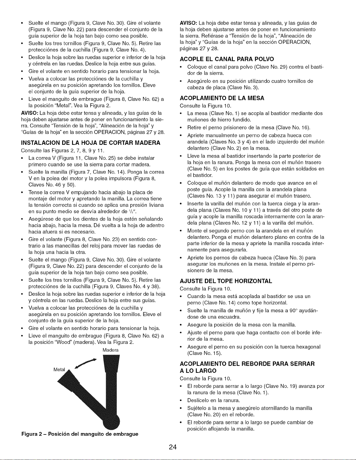
Madera
Metal
Figura 2 - Posici6n del manguito de embrague
AVISO: La hoja debe estar tensa y alineada, y las gufas de
la hoja deben ajustarse antes de poner en funcionamiento
la sierra. Refi6rase a "Tensi6n de la hoja", "Alineaci6n de
la hoja" y "Gufas de la hoja" en la secci6n OPERACION,
paginas 27 y 28.
ACOPLE EL CANAL PARA POLVO
• Coloque el canal para polvo (Clave No. 29) contra el basti-
dor de la sierra.
• Aseg_relo en su posici6n utilizando cuatro tornillos de
cabeza de placa (Clave No. 3).
ACOPLAMIENTO DE LA MESA
Consulte la Figura 10.
• La mesa (Clave No. 1) se acopla al bastidor mediante dos
muSones de hierro fundido.
• Retire el perno prisionero de la mesa (Clave No. 16).
• Apriete manualmente un perno de cabeza hueca con
arandela (Claves No. 3 y 4) en el lado izquierdo del mu56n
delantero (Clave No. 2) en la mesa.
• Lleve la mesa al bastidor insertando la parte posterior de
la hoja en la ranura. Ponga la mesa con el mu56n trasero
(Clave No. 5) en los postes de gufa que estan soldados en
el bastidor.
• Coloque el mu56n delantero de modo que avance en el
poste gufa. Acople la manilla con la arandela plana
(Claves No. 13 y 11) para asegurar el mu56n trasero.
• Inserte la varilla del mu56n con la tuerca ciega y la aran-
dela plana (Claves No. 10 y 11) a trav6s del otro poste de
gufa y acople la manilla roscada internamente con la aran-
dela plana (Claves No. 12 y 11) a la varilla del mu56n.
° Monte el segundo perno con la arandela en el mu56n
delantero. Ponga el mu56n delantero piano en contra de la
parte inferior de la mesa y apriete la manilla roscada inter-
namente para asegurarla.
• Apriete los pernos de cabeza hueca (Clave No. 3) para
asegurar los mu5ones en la mesa. Instale el perno pri-
sionero de la mesa.
AJUSTE DEL TOPE HORIZONTAL
Consulte la Figura 10.
• Cuando la mesa esta acoplada al bastidor se usa un
perno (Clave No. 14) como tope horizontal.
• Suelte la manilla de mu56n y fije la mesa a 90° ayudAn-
dose de una escuadra.
• Asegure la posici6n de la mesa con la manilla.
• Ajuste el perno para que haga contacto con el borde infe-
rior de la mesa.
• Asegure el perno en su posici6n con la tuerca hexagonal
(Clave No. 15).
ACOPLAMIENTO DEL REBORDE PARA SERRAR
A LO LARGO
Consulte la Figura 10.
• El reborde para serrar a Io largo (Clave No. 19) avanza por
la ranura de la mesa (Clave No. 1).
• Deslicelo en la ranura.
• Suj6telo a la mesa y aseg_relo atornillando la manilla
(Clave No. 20) en el reborde.
• El reborde para serrar a Io largo se puede cambiar de
posici6n aflojando la manilla.
24
ALINEACION DE LA MESA
Consulte la Figura 10.
• La mesa se debe alinear correctamente de modo que la
hoja quede en angulo recto con la mesa y que el reborde
para serrar a Io largo quede alineado con la hoja.
• Asegure la mesa en posici6n horizontal. Monte el reborde
para serrar a Io largo en la mesa. Deslicelo para que
quede junto a la hoja sin hacer contacto con ella. Asegure
el reborde.
• Verifique que la hoja quede paralela al reborde para serrar
a Io largo. Si la hoja y el reborde no quedan paralelos, afloje
el mango y la manilla (Claves No. 12 y 13) en los muSones
(Claves No. 2 y 5). Ajuste la posici6n de la mesa de modo
que la hoja y el reborde queden paralelos. Asegure la posi-
ci6n de la mesa apretando el mango y la manilla.
• Despu_s del montaje, es necesario alinear la mesa para
que la hoja pase por el centro de la ranura en el inserto
de la mesa.
• Para mover la mesa hacia los lados, suelte los pernos
(Clave No. 3) en los muSones (Claves No. 2 y 5). Mueva la
mesa hacia la izquierda o derecha hasta que la hoja pase
por el centro de la ranura. Apriete los pernos y aseg_rese
de que la mesa quede fija en su lugar mientras Io hace.
INSTALACION DE LA CORREA V (CORTAR METAL)
Consulte las Figuras 6, 7 y 11.
• La sierra de banda utiliza un sistema de impulsi6n de
poleas escalonadas para proporcionar una variedad de
velocidades de hoja para cortar metales.
• Suelte la manilla (Figura 7, Clave No. 14). Ponga la correa
(Figura 11, Clave No. 25) en la polea tensora y la polea
del motor (Figura 11, Claves No. 23 y 26) con la correa V
en el lugar deseado en las poleas. (Vea la Figura 6,
Velocidades de la hoja, pagina 28.)
• No apriete demasiado las correas V. La tensi6n excesiva
en la correa reduce su duraci6n. La correa tiene la tensi6n
correcta si cuando se aplica una presi6n liviana en su
punto medio se desvia alrededor de 1/2".
• Tense la correa V empujando hacia abajo la placa de
montaje del motor y apretando el perno de cabeza hexa-
gonal y la tuerca hexagonal.
MONTAJE DE LA SIERRA EN EL PISO
• Si la sierra no esta colocada en forma correcta en una
superficie plana, puede desarrollar una vibraci6n excesiva.
• M6ntela en una superficie plana y nivelada a trav_s de los
agujeros en la parte superior de la base.
Consulte las Figuras 3, 4 y 5.
MOTOR
El motor de CA de 115/230 voltios tiene las siguientes
especificaciones:
Caballaje (servicio continuo) ......................... 1
Voltaje ..................................... 115/230
Amperaje ...................................... 14/7
Frecuencia (Hz) .................................. 60
Fase .................................... Monofasico
RPM ......................................... 1720
FUENTE DE ALIMENTACION
El motor ha sido diseSado para funcionar al voltaje y frecuen-
cia especificados. Las cargas normales se pueden manejar
con seguridad con voltajes no mayores de 10% por encima o
por debajo del voltaje especificado.
El hacer funcionar la unidad en voltajes fuera del rango
especificado puede sobrecalentar la herramienta y quemar el
motor. Para cargas pesadas es necesario que el voltaje en
los terminales del motor no sea inferior al voltaje especifica-
do. La fuente de alimentaci6n del motor se controla mediante
un interruptor oscilante de enclavamiento bipolar. Extraiga la
Ilave para evitar el uso no autorizado.
INSTRUCCIONES PARA LA CONEXION A TIERRA
ADVERTENCIA: Si no se conecta correctamente el con-
ductor a tierra del equipo, se corre el riesgo de un electro-
choque. El equipo debe estar conectado a tierra mientras se
usa para proteger al operador de un electrochoque.
Si no comprende las instrucciones de conexi6n a tierra o
tiene dudas en cuanto a si la herramienta esta correctamente
conectada a tierra, consulte a un electricista calificado.
A fin de protegerlo contra una descarga el_ctrica, esta
herramienta esta equipada con un cord6n de tres con-
ductores, aprobado y clasificado para 300 V, y con un
enchufe de tres puntas del tipo de conexi6n a tierra.
El enchufe de conexi6n a tierra debera conectarse directa-
mente a un z6calo para 3 clavijas instalado y conectado
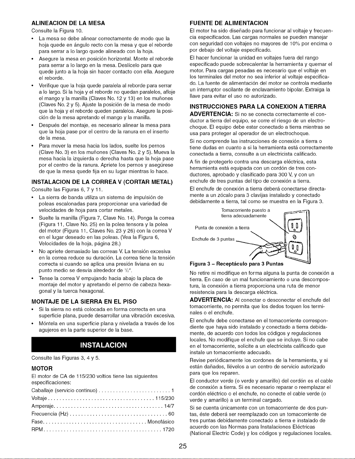
debidamente a tierra, tal como se muestra en la Figura 3.
Tomacorrientepuesto a =._-.-::
tierra adecuadamente _
Punta de a tierraconexi6n
Enchufede 3 puntas
Figura 3 - Receptaculo para 3 Puntas
No retire ni modifique en forma alguna la punta de conexi6n a
tierra. En caso de un mal funcionamiento o una descompos-
tura, la conexi6n a tierra proporciona una ruta de menor
resistencia para la descarga el_ctrica.
ADVERTENCIA: AI conectar o desconectar el enchufe del
tomacorriente, no permita que los dedos toquen los termi-
nales o el enchufe.
El enchufe debe conectarse en el tomacorriente correspon-
diente que haya sido instalado y conectado a tierra debida-
mente, de acuerdo con todos los c6digos y regulaciones
locales. No modifique el enchufe que se incluye. Si no cabe
en el tomacorriente, solicite a un electricista calificado que
instale un tomacorriente adecuado.
Revise peri6dicamente los cordones de la herramienta, y si
estAn daSados, II_velos a un centro de servicio autorizado
para que los reparen.
El conductor verde (o verde y amarillo) del cord6n es el cable
de conexi6n a tierra. Si es necesario reparar o reemplazar el
cord6n el_ctrico o el enchufe, no conecte el cable verde (o
verde y amarillo) a un terminal cargado.
Si se cuenta _nicamente con un tomacorriente de dos pun-
tas, _ste debera ser reemplazado con un tomacorriente de
tres puntas debidamente conectado a tierra e instalado de
acuerdo con las Normas para Instalaciones El_ctricas
(National Electric Code) y los c6digos y regulaciones locales.
25
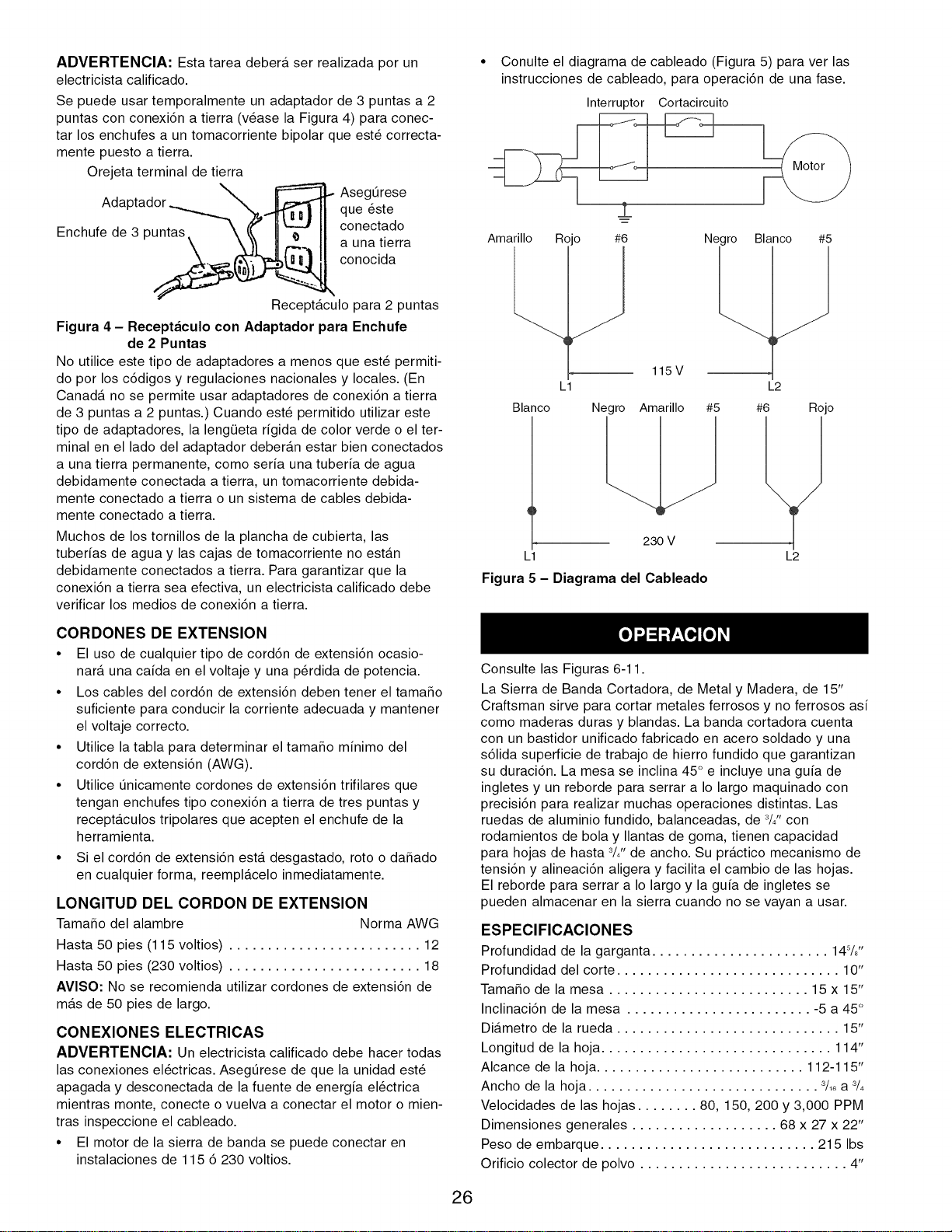
ADVERTENClA: Esta tarea deber& ser realizada por un
electricista calificado.
Se puede usar temporalmente un adaptador de 3 puntas a 2
puntas con conexi6n a tierra (v_ase la Figura 4) para conec-
tar los enchufes a un tomacorriente bipolar que est_ correcta-
mente puesto a tierra.
Orejeta terminal de tierra
Ada
Enchufe de 3 puntas
AsegOrese
que _ste
conectado
a una tierra
conocida
Receptaculo para 2 puntas
Figura 4 - Receptaculo con Adaptador para Enchufe
de 2 Puntas
No utilice este tipo de adaptadores a menos que est_ permiti-
do por los c6digos y regulaciones nacionales y locales. (En
Canada no se permite usar adaptadores de conexi6n a tierra
de 3 puntas a 2 puntas.) Cuando est_ permitido utilizar este
tipo de adaptadores, la lengQeta rigida de color verde o el ter-
minal en el lado del adaptador deberan estar bien conectados
a una tierra permanente, como seria una tuberia de agua
debidamente conectada a tierra, un tomacorriente debida-
mente conectado a tierra o un sistema de cables debida-
mente conectado a tierra.
Muchos de los tornillos de la plancha de cubierta, las
tuberias de agua y las cajas de tomacorriente no estan
debidamente conectados a tierra. Para garantizar que la
conexi6n a tierra sea efectiva, un electricista calificado debe
verificar los medios de conexi6n a tierra.
• Conulte el diagrama de cableado (Figura 5) para ver las
instrucciones de cableado, para operaci6n de una fase.
Interruptor Cortacircuito
&
Amarillo Roo #6
Blanco
Negro Blanco #5
23O V
L1
Figura 5 - Diagrama del Cableado
115V
L1 L2
Negro Amarillo #5 #6 Rojo
L2
CORDONES DE EXTENSION
• El uso de cualquier tipo de cord6n de extensi6n ocasio-
nara una caida en el voltaje y una p@dida de potencia.
• Los cables del cord6n de extensi6n deben tener el tamaSo
suficiente para conducir la corriente adecuada y mantener
el voltaje correcto.
• Utilice la tabla para determinar el tamaSo minimo del
cord6n de extensi6n (AWG).
• Utilice _nicamente cordones de extensi6n trifilares que
tengan enchufes tipo conexi6n a tierra de tres puntas y
recept&culos tripolares que acepten el enchufe de la
herramienta.
• Si el cord6n de extensi6n est& desgastado, roto o da_ado
en cualquier forma, reemplacelo inmediatamente.
LONGITUD DEL CORDON DE EXTENSION
Tama_o del alambre Norma AWG
Hasta 50 pies (115 voltios) ......................... 12
Hasta 50 pies (230 voltios) ......................... 18
AVISO: No se recomienda utilizar cordones de extensi6n de
mas de 50 pies de largo.
CONEXIONES ELECTRICAS
ADVERTENCIA: Un electricista calificado debe hacer todas
las conexiones el_ctricas. Aseg_rese de que la unidad est_
apagada y desconectada de la fuente de energia el_ctrica
mientras monte, conecte o vuelva a conectar el motor o mien-
tras inspeccione el cableado.
• El motor de la sierra de banda se puede conectar en
instalaciones de 115 6 230 voltios.
Consulte las Figuras 6-11.
La Sierra de Banda Cortadora, de Metal y Madera, de 15"
Craftsman sirve para cortar metales ferrosos y no ferrosos asi
como maderas duras y blandas. La banda cortadora cuenta
con un bastidor unificado fabricado en acero soldado y una
s61ida superficie de trabajo de hierro fundido que garantizan
su duraci6n. La mesa se inclina 45° e incluye una guia de
ingletes y un reborde para serrar a I0 largo maquinado con
precisi6n para realizar muchas operaciones distintas. Las
ruedas de aluminio fundido, balanceadas, de 3/,, con
rodamientos de bola y Ilantas de goma, tienen capacidad
para hojas de hasta d4" de ancho. Su practico mecanismo de
tensi6n y alineaci6n aligera y facilita el cambio de las hojas.
El reborde para serrar a I0 largo y la guia de ingletes se
pueden almacenar en la sierra cuando no se vayan a usar.
ESPEClFICAClONES
Profundidad de la garganta ....................... 145/8''
Profundidad del corte ............................. 10"
Tama_o de la mesa .......................... 15 x 15"
Inclinaci6n de la mesa ........................ -5 a 45 °
DiAmetro de la rueda ............................. 15"
Longitud de la hoja .............................. 114"
Alcance de la hoja ........................... 112-115"
Ancho de la hoja .............................. 3/1_a 3/4
Velocidades de las hojas ........ 80, 150, 200 y 3,000 PPM
Dimensiones generales ................... 68 x 27 x 22"
Peso de embarque ............................ 215 Ibs
Orificio colector de polvo ........................... 4"
26

PRECAUClON: Tenga siempre en cuenta las siguientes
precauciones:
• Aseg_rese de que las guias de las hojas y los rodamien-
tos de empuje est_n colocados y ajustados correctamente
para evitar que la hoja se mueva hacia un lado y hacia
atr&s. Ajuste la guia superior para que apenas quede
separada de la pieza de trabajo.
• Verifique que la hoja tenga la tensi6n y alineaci6n correc-
tas. No ponga demasiada tensi6n en la hoja para evitar
que se desgaste prematuramente y se rompa. Evite que
se aplique una tensi6n insuficiente en la hoja para impedir
que se mueva de atr&s hacia delante y de lado a lado a
medida que corta.
• Utilice la hoja y velocidad adecuadas para la operaci6n de
corte.
• Despu_s de encender la sierra, permita que la hoja
alcance la velocidad completa antes de intentar Ilevar a
cabo ninguna operaci6n de corte.
• Soporte la pieza de trabajo correctamente y use una ali-
mentaci6n uniforme y constante para guiar el trabajo a
trav_s del corte. Use palos o bloques de empuje cuando
sea necesario.
• Mantenga las manos alejadas y fuera de la trayectoria de
las partes m6viles.
• Utilice siempre protecci6n para los ojos.
ADVERTENClA: Parte del polvo producido por el lijado
mec&nico, serrado, esmerilado, taladrado y otras tareas de
construcci6n contiene sustancias quimicas que pueden oca-
sionar c&ncer, malformaciones cong_nitas u otros daSos
reproductivos.
Algunos ejemplos de estas sustancias quimicas son:
° Plomo proveniente de pinturas con base de plomo.
° Silice cristalino proveniente de ladrillos, cemento y otro
material de mamposteria.
° Ars_nico y cromo proveniente de madera quimicamente
tratada.
El riesgo debido a la exposici6n de estas sustancias quimicas
depende de la frecuencia con la cual realice este tipo de tra-
bajo. Para reducir la exposici6n a estas sustancias quimicas:
trabaje en un &rea bien ventilada y utilice equipo de seguri-
dad aprobado. Cuando trabaje con este tipo de herramientas,
utilice siempre una m&scara para la cara o respirador ade-
cuadamente ajustados, aprobados por OSHA/NIOSH.
EXTRACClON DE LA HOJA
Consulte las Figuras 8, 9 y 10.
ADVERTENClA: Desconecte la sierra de banda de la
fuente de alimentaci6n al cambiar o ajustar las hojas. Utilice
guantes de cuero cuando trabaje con las hojas de la sierra de
banda. Nunca utilice guantes cuando opere la sierra.
• Suelte los tres tornillos (Figura 9, Clave No. 5). Retire las
protecci6nes de la cuchilla (Figura 9, Claves No. 4 y 38).
Suelte las tuercas hexagonales (Figura 8, Clave No. 30) y
rote el volante (Figura 8, Clave No. 23) para soltar la ten-
si6n de la hoja. Tenga cuidado; la hoja puede saltarse
fuera de la sierra cuando se suelta la tensi6n. Remueva el
perno prisionero de la mesa (Figura 10, Clave No. 16),
saque la hoja destensada y ponga la otra.
INSTALAClON DE LA HOJA
• Aunque muchos de los ajustes no se pueden modificar
cuando se ha extraido la hoja, se debe revisar cada ajuste
antes de usar una hoja reci_n instalada.
• Acate las precauciones de seguridad cada vez que use la
sierra.
• Aseg_rese de que los dientes de la hoja est_n seSalando
hacia abajo, hacia la mesa. D_ vuelta a la hoja de adentro
hacia afuera si es necesario.
• Deslice la hoja nueva en la ranura de la mesa y sobre
las ruedas superior e inferior de la hoja y c_ntrela en las
ruedas. Deslice la hoja entre sus guias. Vuelva a colocar
el perno prisionero de la mesa. Vuelva a colocar las protec-
ci6nes de la cuchilla despu_s de la guiia de la hoja el ajuste.
• Tense y alinee la hoja tal como se describe en las sec-
ciones siguientes.
TENSION DE LA HOJA
Consulte la Figura 8.
• Tense la hoja girando el volante (Clave No. 23). Asegt_rese
de que las guias de la hoja no interfieran con su paso.
• Apriete la hoja hasta que tenga la tensi6n correcta.
• Una hoja con la tensi6n correcta sonar& un poco cuando
se toca la parte trasera de la hoja (como una cuerda de
instrumento).
AVISO: Verifique la tensi6n de la hoja nueva. Es posible que
sea necesario tensarla m&s al cabo de unos minutos de fun-
cionamiento.
ALINEAClON DE LA HOJA
Consulte la Figura 8.
• Alinee la hoja despu_s que se haya tensado. Un cambio
en la tensi6n de la hoja afectara la alineaci6n de la rueda.
• La alineaci6n correcta se Iogra cuando la rueda impulsora
y la rueda Ioca estan alineadas. La manilla (Clave No. 29)
se usa para inclinar la barra de alineaci6n (Clave No. 13) y
alinear las ruedas de la hoja.
• Suelte las tuercas hexagonales (Clave No. 30) que asegu-
ran la manilla de alineaci6n (Clave No. 29). Gire la rueda
Ioca (Clave No. 7) manualmente y observe el avance de la
hoja en las ruedas.
• Si la hoja avanza alejada del armario, gire la manilla en el
sentido de las manecillas del reloj para inclinar la rueda
Ioca hacia arriba.
• Si la hoja avanza acerc&ndose al armario, gire la manilla
de alineaci6n en sentido contrario alas manecillas del
reloj.
• Cuando la hoja tenga la alineaci6n correcta, fije esa posi-
ci6n sujetando la manilla y apretando las tuercas hexago-
nales (Clave No. 30) en direcci6n contraria al armario.
ALINEACION DE LA RUEDA IMPULSORA
Consulte la Figura 11.
AVISO: $61o trate de ajustar la alineaci6n de la rueda impul-
sora si la hoja no puede alinearse correctamente con el
ajuste de alineaci6n solamente.
• Una hoja sometida a mucha tensi6n puede tambi_n
desalinear la rueda impulsora.
• Ajuste la alineaci6n de la rueda impulsora mediante los
pernos de cabeza hexagonal (Claves No. 8 y 30).
27

GUIAS DE LA HOJA
AVISO: Ajuste las guias de la hoja s61odespu_s de que _sta
haya sido tensada y alineada correctamente.
• Las guias de la hoja la soportan por los lados y la parte
trasera e impiden que se tuerza o desvie.
• Las guias de la hoja no deben tocar la hoja si no hay
ninguna pieza de trabajo en contacto con la hoja. Ajuste
las guias como se describe en las secciones siguientes.
GUIAS DE LA HOJA SUPERIORES
Consulte la Figura 9.
• Las guias de la hoja superiores emplean pasadores de
guia como soporte lateral y un rodamiento de bola en un
pasador de ajuste de la parte trasera.
• El puntal de la guia superior (Clave No. 13) se debe colo-
car de modo que la guia a cualquier lado de la hoja
soporte tanta anchura de la hoja como sea posible sin
interferir con el conjunto de dientes.
• Ajuste la profundidad del puntal soltando los pernos
(Claves No. 9 y 12) y deslizando los puntales a su lugar.
Asegure la posici6n de la pieza fundida de la guia supe-
rior apretando los pernos.
• Suelte los tornillos de fijaci6n (Clave No. 15) y ajuste los
pasadores de guia (Clave No. 14) al lado de la hoja. Use
un calibrador de cinta para verificar que los pasadores de
guia est_n a 0.002" de la hoja.
• Asegure el ajuste apretando los tornillos de fijaci6n.
• Ajuste el rodamiento de empuje (Clave No. 17) en la parte
trasera de la hoja soltando el tornillo de fijaci6n (Clave No. 15).
• Ponga el rodamiento de empuje a 0.002" de la parte
trasera de la hoja.
• Asegure la posici6n del rodamiento de empuje apretando
el tornillo de fijaci6n.
• Ajuste la altura de la pieza fundida de la guia superior para
que quede a 1/,, de la pieza de trabajo. Suelte la manilla
(Clave No. 30) y rote la manilla de ajuste de la altura (Clave
No. 22) hasta que el puntal de la guia supe-rior de la hoja
quede a W' de la pieza de trabajo. Apriete la manilla.
GUIAS DE LA HOJA INFERIORES
Consulte la Figura 9.
• Las guias de la hoja inferiores usan dos bloques de guia
como soporte lateral. El puntal de la guia inferior est&
espaciado cerca de la superficie de la mesa para mini-
mizar la Iongitud no soportada por la hoja.
• Suelte el tornillo (Clave No. 5) y retire la protecci6n de la
cuchilla (Clave No. 38).
• Suelte el perno (Clave No. 19) para colocar el puntal de la
guia inferior en el bloque de alineaci6n (Clave No. 31).
Ajuste el puntal de la guia inferior de modo que los blo-
ques de guia no interfieran con el conjunto de la hoja.
Suelte los tornillos de fijaci6n (Clave No. 23) de los blo-
ques de guia (Claves No. 21 y 34) y ajuste los bloques de
guia a 0.002" de cada lado de la hoja.
• Ajuste el rodamiento de empuje (Clave No. 36) en la parte
trasera de la hoja soltando el tornillo de fijaci6n (Clave No.
23). Ponga el rodamiento de empuje a 0.002" de la parte
trasera de la hoja. Asegure la posici6n del rodamiento de
empuje apretando el tornillo de fijaci6n.
• Vuelva a colocar la protecci6n de la cuchilla y aseg_rela
en su posici6n.
SELECClON DE LA HOJA
• Las hojas varian seg_n el tipo de material, tamaSo de la
pieza de trabajo y tipo de corte que se vaya a realizar.
• Las caracteristicas que diferencian alas hojas son el
ancho, el espesor y el paso.
ANCHO DE LA HOJA
• El ancho de la hoja es la distancia desde la punta del
diente hasta la parte trasera de la hoja.
• El ancho de la hoja afecta su rigidez. Una hoja m&s ancha
se desvia menos y produce un corte m&s recto.
• El ancho de la hoja tambi_n limita el radio m&s pequeSo
que se puede cortar. Una hoja de W' de ancho puede cor-
tar alrededor de 1/2"de radio.
ESPESOR DE LA HOJA
• El espesor de la hoja es la distancia entre sus lados.
Mientras mayor es su espesor, mayor es su rigidez y m&s
fuertes sus dientes.
• Una hoja angosta y de mayor espesor se puede usar para
cortar curvas mientras que una hoja ancha y de menor
espesor se puede usar para hacer cortes largos y rectos.
PASO DE LA HOJA
• El paso es el n_mero de dientes por pulgada o el tama_o
del diente. Una hoja con m&s dientes por pulgada produce
un corte m&s uniforme.
• El tipo de material que se est& cortando determina el
n_mero de dientes que tienen que estar en contacto con
el trabajo.
• En el caso de metales blandos, la cuchilla adecuada debe
tener entre 6 y 12 dientes por pulgada.
• Cuando se corten metales m&s duros, en cuyo caso el
golpe es m&s nocivo, se recomienda una hoja de 12 a 24
dientes por pulgada.
• En el caso de maderas blandas, la cuchilla adecuada
debe tener entre 4 y 8 dientes por pulgada.
• En el caso de maderas duras, la cuchilla adecuada debe
tener entre 8 y 12 dientes por pulgada.
• Siempre debe haber al menos tres dientes en contacto
con el corte para evitar el golpe de la hoja.
• La hoja se golpea cuando el paso es muy grande y
el diente encuentra demasiado material. Esto puede
desgarrar los dientes de la hoja.
• Los fabricantes de hojas est&n en capacidad de suministrar
informaci6n sobre las hojas para aplicaciones especfficas.
VELOCIDAD DE LA HOJA
Consulte la Figura 6, la p&gina 27.
• La intensidad de la fuerza con que la hoja corta esta
determinada por su velocidad.
• Las velocidades de corte altas se aplican a materiales
blandos, en cuyo caso se requiere menor fuerza y se
desea eliminar material a mayor velocidad.
• Las velocidades de corte bajas se aplican a materiales
duros, en cuyo caso se requiere mayor fuerza.
• Para cambiar la velocidad de la hoja ponga la correa V en
la configuraci6n correcta (Vea la Figura 6). Vuelva a colo-
car y tensar la correa V tal como se describe en la sec-
ci6n siguiente.
28
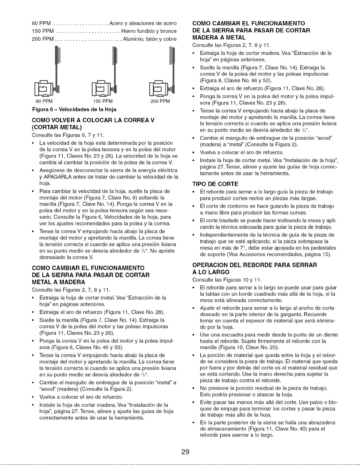
80 PPM ................... Acero y aleaciones de acero
150 PPM ...................... Hierro fundido y bronce
200 PPM ....................... Aluminio, lat6n y cobre
80 PPM 150 PPM 200 PPM
Figura 6 - Velocidades de la Hoja
COMO VOLVER A COLOCAR LA CORREA V
(CORTAR METAL)
Consulte las Figuras 6, 7 y 11.
• La velocidad de la hoja est& determinada por la posici6n
de la correa V en la polea tensora yen la polea del motor
(Figura 11, Claves No. 23 y 26). La velocidad de la hoja se
cambia al cambiar la posici6n de la polea de la correa V.
• Aseg_rese de desconectar la sierra de la energfa el_ctrica
y APAGARLA antes de tratar de cambiar la velocidad de la
hoja.
• Para cambiar la velocidad de la hoja, suelte la placa de
montaje del motor (Figura 7, Clave No. 9) soltando la
manilla (Figura 7, Clave No. 14). Ponga la correa V en la
polea del motor yen la polea tensora seg_n sea nece-
sario. Consulte la Figura 6, Velocidades de la hoja, para
ver los ajustes recomendados para la polea y la correa.
• Tense la correa V empujando hacia abajo la placa de
montaje del motor y apretando la manilla. La correa tiene
la tensi6n correcta si cuando se aplica una presi6n liviana
en su punto medio se desvfa alrededor de 1/2".No apriete
demasiado la correa V.
COMO CAMBIAR EL FUNCIONAMIENTO
DE LA SIERRA PARA PASAR DE CORTAR
METAL A MADERA
Consulte las Figuras 2, 7, 8 y 11.
• Extraiga la hoja de cortar metal. Vea"Extracci6n de la
hoja" en p&ginas anteriores.
• Extraiga el aro de refuerzo (Figura 11, Clave No. 28).
• Suelte la manilla (Figura 7, Clave No. 14). Extraiga la
correa V de la polea del motor y las poleas impulsoras
(Figura 11, Claves No. 23 y 26).
• Ponga la correa V en la polea del motor y la polea impul-
sora (Figura 8, Claves No. 46 y 50).
• Tense la correa V empujando hacia abajo la placa de
montaje del motor y apretando la manilla. La correa tiene
la tensi6n correcta si cuando se aplica una presi6n liviana
en su punto medio se desvfa alrededor de 1/2".
• Cambie el manguito de embrague de la posici6n "metal" a
"wood" (madera) (Consulte la Figura 2).
• Vuelva a colocar el aro de refuerzo.
• Instale la hoja de cortar madera. Vea "lnstalaci6n de la
hoja", p&gina 27. Tense, alinee y ajuste las gufas de hoja
correctamente antes de usar la herramienta.
COMO CAMBIAR EL FUNCIONAMIENTO
DE LA SIERRA PARA PASAR DE CORTAR
MADERA A METAL
Consulte las Figuras 2, 7, 8 y 11.
• Extraiga la hoja de cortar madera. Vea"Extracci6n de la
hoja" en p&ginas anteriores.
• Suelte la manilla (Figura 7, Clave No. 14). Extraiga la
correa V de la polea del motor y las poleas impulsoras
(Figura 8, Claves No. 46 y 50).
• Extraiga el aro de refuerzo (Figura 11, Clave No. 28).
• Ponga la correa V en la polea del motor y la polea impul-
sora (Figura 11, Claves No. 23 y 26).
• Tense la correa V empujando hacia abajo la placa de
montaje del motor y apretando la manilla. La correa tiene
la tensi6n correcta si cuando se aplica una presi6n liviana
en su punto medio se desvfa alrededor de 1/2".
• Cambie el manguito de embrague de la posici6n "wood"
(madera) a "metal" (Consulte la Figura 2).
• Vuelva a colocar el aro de refuerzo.
• Instale la hoja de cortar metal. Vea "lnstalaci6n de la hoja",
p&gina 27. Tense, alinee y ajuste las gufas de hoja correc-
tamente antes de usar la herramienta.
TIPO DE CORTE
• El reborde para serrar a Io largo gufa la pieza de trabajo
para producir cortes rectos en piezas m&s largas.
• El corte de contorno se hace guiando la pieza de trabajo
a mano libre para producir las formas curvas.
• El corte biselado se puede hacer inclinando la mesa y apli-
cando la t_cnica adecuada para guiar la pieza de trabajo.
• Independientemente de la t_cnica de guia de la pieza de
trabajo que se est_ aplicando, si la pieza sobrepasa la
mesa en m&s de 7", debe estar apoyada en los pedestales
de soporte (Vea Accesorios recomendados, p&gina 15).
OPERACION DEL REBORDE PARA SERRAR
A LO LARGO
Consulte las Figuras 10 y 11.
• El reborde para serrar a Io largo se puede usar para guiar
la tablas con un borde cuadrado m&s all& de la hoja, si la
mesa est& alineada correctamente.
• Ajuste el reborde para serrar a Io largo al ancho de corte
deseado en la parte interior de la garganta. Recuerde
tomar en cuenta el espesor de material que ser& elimina-
do por la hoja.
• Use una escuadra para medir desde la punta de un diente
hasta el reborde. Sujete firmemente el reborde con la
manilla (Figura 10, Clave No. 20).
• La porci6n de material que queda entre la hoja y el rebor-
de se considera la pieza de trabajo. El material que queda
por fuera y por detr&s del corte es el material residual que
se est& cortando. Use la mano derecha para sujetar la
pieza de trabajo contra el reborde.
• No presione la porci6n residual de la pieza de trabajo.
Esto podrfa presionar o atascar la hoja.
• Evite pasar las manos m&s all& del corte. Use palos o blo-
ques de empuje para terminar los cortes y pasar la pieza
de trabajo m&s all& de la hoja.
• En la parte posterior de la sierra se halla una abrazadera
de almacenamiento (Figura 11, Clave No. 40) para el
reborde para aserrar a Io largo.
29

SERRADO DE CONTORNO
• Cuando se sierre el contorno use ambas manos para
mantener la pieza de trabajo horizontal sobre la mesa y
guiarla por la trayectoria deseada.
• Evite poner las manos en linea con la hoja. Si se le res-
balan, pueden hacer contacto con la hoja.
• Trate de pararse hacia la parte delantera de la sierra y
ponga las manos sobre la parte de la mesa que esta a la
derecha de la hoja y antes del corte.
• Corte las esquinas pequeSas aserrando a su alrededor.
Sierre para eliminar el material residual hasta Iograr la
forma deseada.
CORTE BISELADO
Consulte la Figura 10.
• Bisele inclinando la mesa. Suelte el mango y la manilla
(Claves No. 12 y 13) e incline la mesa hasta la posici6n
deseada.
• Use una escuadra o transportador para establecer el angulo
y fije la mesa en esa posici6n con la manilla. Tenga cuidado
cuando sostenga la pieza de trabajo mientras esta bise-
lando. No permita que la pieza quede colgando en la hoja.
GUIA DE INGLETES
Consulte la Figura 10.
• Use la gufa de ingletes para asegurar y sujetar la pieza de
trabajo en el angulo deseado y producir asi cortes en angu-
Io. Use la escala para ajustar la gufa en el angulo deseado.
• No use nunca simultaneamente la gufa de ingletes y el
reborde para serrar a Io largo. La hoja se puede atascar
en la pieza de trabajo. El operador puede lesionarse y/o la
pieza de trabajo se puede daSar.
• En la parte posterior de la sierra se halla una abrazadera
de almacenamiento (Clave No. 33) para la gu[a de ingletes.
ESCOBILLA PARA LIMPIAR LA HOJA
Consulte la Figura 8.
• Asegt_rese de que la escobilla (Clave No. 36) haga contac-
to con la hoja para eliminar adecuadamente los cuerpos
extraSos que pueda tener la rueda impulsora.
ADVERTENCIA: Asegt_rese de que la unidad est_
desconectada de la fuente de alimentaci6n el_ctrica antes
de tratar de dar servicio o retirar cualquier componente.
LIMPIEZA
• Mantenga la maquina y el taller limpios. No permita que el
aserrin se acumule en la sierra de banda.
• Mantenga las ruedas limpias. Los residuos en las ruedas
harAn que la hoja se desalinee y resbale.
• Mantenga los mecanismos y superficies roscadas o
deslizantes limpios y sin cuerpos extraSos.
• Haga funcionar la sierra de banda cortadora con un
colector de polvo para minimizar la limpieza.
LUBRICACION
• Los rodamientos de bola protegidos estan permanente-
mente lubricados y no necesitan mas lubricaci6n.
• Se puede aplicar un poco de aceite de maquina a los
mecanismos de tensi6n de la hoja y alas superficies
deslizantes o roscadas.
• De vez en cuando aplique una capa de cera del tipo
usado en autom6viles a la parte superior de la mesa
para mantenerla pulida y sin corrosi6n.
MANTENGA LA SIERRA DE BANDA EN BUENAS
CONDICIONES
• Si el cord6n el_ctrico esta desgastado, cortado o da_ado
en cualquier manera, reemplAcelo inmediatamente.
• Si est& desgastada, reemplace la correa V y la hoja.
Reemplace toda parte que est_ daSada o que falte.
• Valgase de la lista de piezas incluida para solicitar piezas
de repuesto.
30

SINTOMA
Las hojas se rompen
excesivamente
La hoja se desafila
prematuramente
Cortes chuecos
Cortes asperos
La hoja se estA torciendo
o esta desgastada
anormalmente en su
parte lateral/trasera.
Los dientes se estan
desgarrando de la hoja
CAUSAS(S) POSIBLE(S)
1. El material no esta seguro en la mesa
2. Velocidad o alimentaci6n incorrecta
3. Los dientes son demasiado gruesos para
el material
4. Tensi6n de la hoja incorrecta
5. Los dientes entran en contacto con la
pieza de trabajo antes de serrar
6. La hoja roza la brida de la rueda
7. Las guias estan desalineadas
8. El espesor de la hoja es excesivo para el
diametro de la rueda
9. Partiduras en la soldadura
1. La hoja es muy gruesa
2. Velocidad de la hoja excesiva
3. Presi6n de alimentaci6n inadecuada
4. Puntos duros o escamas en el material
o sobre 51
5,
6.
7.
1.
2.
3.
4.
5.
6.
7.
2,
3.
4.
El motor esta funcionando 1.
muy caliente 2.
Endurecimiento de la pieza de trabajo
La hoja esta instalada de atras para
adelante
La tensi6n de la hoja no es suficiente
El trabajo no esta cuadrado
La velocidad de alimentaci6n es muy alta
Las guias de la hoja no estan ajustadas
correctamente
La tensi6n de la hoja no es suficiente
La guia de la hoja superior esta demasiado
alejada de la pieza de trabajo
Hoja desafilada
Velocidad incorrecta
8. El conjunto de la guia de la hoja esta suelto o
el rodamiento de empuje de la hoja esta suelto
1. Velocidad o alimentaci6n excesivas
2. La hoja es muy gruesa
1. El corte esta atascando la hoja
2. Las guias de la hoja o el rodamiento estan
desgastados
3. Las guias de la hoja o los rodamientos no
estan ajustados correctamente
4. Los puntales de la guia de la hoja estan
sueltos
1. Los dientes son demasiado gruesos para
el trabajo
La velocidad de alimentaci6n es muy alta
La pieza de trabajo esta vibrando
Los dientes se estan Ilenando de material
3,
La tensi6n de la hoja es muy alta
La hoja es demasiado gruesa para la pieza
de trabajo (fipico cuando se cortan tubos)
La hoja es muy fina para el trabajo (tipico
cuando se corta material pulido o blando)
Exceso de mugre y virutas
MEDIDA CORRECTIVA
1. Cuadre el material sobre la mesa
2. Verifique la velocidad de la hoja (Figura 6, pagina 28)
3. Use una hoja de paso mas fino
4. Tense la hoja correctamente; vea "Operaci6n"
5. Ponga la hoja en contacto con la pieza de trabajo
despu_s de que la sierra haya arrancado y
alcanzado su velocidad maxima
6. Ajuste la alineaci6n de la rueda adecuadamente
7. Ajuste las guias de la hoja correctamente
8. Use una hoja de menor espesor
9. Cambie la hoja
1. Use una hoja de dientes mas finos
2. Intente con una velocidad mas baja
3. Aumente la presi6n poco a poco
4. Reduzca la velocidad; si se trata de escamas,
aumente la velocidad de alimentaci6n y, si se
trata de puntos duros, cambie las hojas
5. Aumente la velocidad de alimentaci6n
6. Retire la hoja, d6blela de adentro hacia afuera y
vu_lvala a instalar
7. Tense la hoja correctamente; vea "Operaci6n"
1. Use el reborde para serrar a Io largo; incline la
mesa a 90° con respecto a la hoja
2. Reduzca la velocidad de alimentaci6n
3. Mueva ambos bloques de guia dentro de 0.002"
de la hoja (use calibrador)
4. Tense la hoja correctamente; vea "Operaci6n"
5. Ajuste la guia superior para que apenas quede
separada de la pieza de trabajo 1/4".
6. Cambie la hoja
7. Revise la velocidad de la hoja; vea la Figura 6,
pagina 28, para verificar las velocidades
recomendadas
8. Apriete el rodamiento de empuje de la hoja dentro
de 0.002" detras de la parte trasera de la hoja
1. Reduzca la velocidad o alimentaci6n
2. Cambiela por una hoja mas fina
1. Disminuya la presi6n de alimentaci6n
2. Reemplace
3. Ajuste las guias de la hoja; vea "Operaci6n"
4. Apriete correctamente
1. Use una hoja de dientes mas finos
2. Disminuya la velocidad de alimentaci6n
3. Sujete la pieza de trabajo firmemente
4. Use una hoja de dientes mas gruesos
1. Reduzca la tensi6n de la hoja
2. Use una hoja de dientes mas finos
3. Use una hoja de dientes mas gruesos
4. 4. Limpie cuidadosamente, aspire el motor y el
mecanismo de cambio de velocidad
La sierra no arranca Conexiones el_ctricas sueltas Haga que un electricista profesional revise las
conexiones el_ctricas
31

Your Home
For repair- in your home-of all major brand appliances,
lawn and garden equipment, or heating and cooling systems,
no matter who made it, no matter who sold it!
For the replacement parts, accessories and
owner's manuals that you need to do-it-yourse If.
For Sears professional installation of home appliances
and items like garage door openers and water heaters.
1-800-4-MY-HOME ® (1-800-469-4663)
Call anytime, day or night(U.S.A, and Canada)
www.sears.com www.sears.ca
Our Home
For repair of carry-in items like vacuums, lawn equipment,
and electronics, call or go on-line for the location of your nearest
Sears Parts & Repair Service Center
1-800-488-1222
Call anytime, day or night (U.S.A. only)
www.sears.com
To purchase a protection agreement (U.S.A.)
or maintenance agreement (Canada) on a product serviced by Sears:
1-800-827-6655 (U.S.A.) 1-800-361-6665 (Canada)
Para pedir servicio de reparacidn
a domicilio, y para ordenar piezas:
1-888-SU-HOGAR ®
(1-888-784-6427)
Au Canada pour service en fran£_ais:
1-800-LE-FOYER Mc
(1-800-533-6937)
www.sears.ca
TM SM
® Registered Trademark / Trademark / Service Mark of Sears Brands, LLC
TM
® Marca Registrada / Marca de Fabrica/SM Marca de Servicio de Sears Brands, LLC
MCMarque de commerce _t_/ Marque depos6e de Sears Brands, LLC © Sears Brands, LLC

