Loading ...
Loading ...
Loading ...
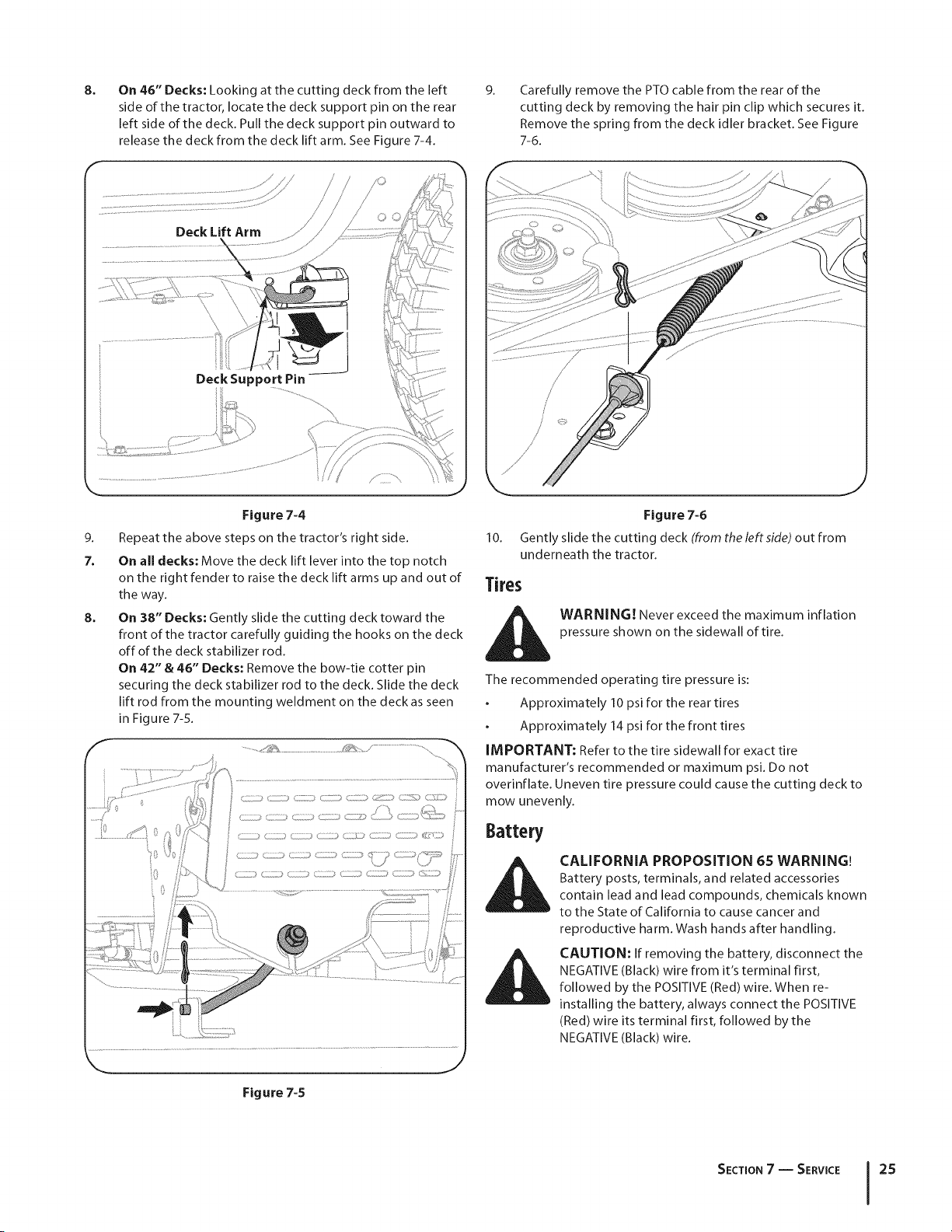
8.
On 46" Decks: Looking at the cutting deck from the left
side of the tractor, locate the deck support pin on the rear
left side of the deck. Pull the deck support pin outward to
release the deck from the deck lift arm. See Figure 7-4.
9.
Carefully remove the PTOcable from the rear of the
cutting deck by removing the hair pin clip which secures it.
Remove the spring from the deck idler bracket. See Figure
7-6.
Deck Lift Arm
Deck Support Pin
9.
7.
8.
Figure 7-4
Repeat the above steps on the tractor's right side.
On all decks: Move the deck lift lever into the top notch
on the right fender to raise the deck lift arms up and out of
the way.
On 38" Decks: Gently slide the cutting deck toward the
front of the tractor carefully guiding the hooks on the deck
off of the deck stabilizer rod.
On 42" & 46" Decks: Remove the bow-tie cotter pin
securing the deck stabilizer rod to the deck. Slide the deck
lift rod from the mounting weldment on the deck as seen
in Figure 7-5.
.................
..............._<_ ................. ..................................
Figure 7-6
10. Gently slide the cutting deck (from the leftside) out from
underneath the tractor.
Tires
i_i WARNING! Never exceed the maximum inflation
pressure shown on the sidewall of tire.
The recommended operating tire pressure is:
Approximately 10 psi for the rear tires
Approximately 14 psi for the front tires
IMPORTANT: Refer to the tire sidewall for exact tire
manufacturer's recommended or maximum psi. Do not
overinflate. Uneven tire pressure could cause the cutting deck to
mow unevenly.
Battery
CALIFORNIA PROPOSITION 65 WARNING!
Battery posts, terminals, and related accessories
contain lead and lead compounds, chemicals known
to the State of California to cause cancer and
reproductive harm. Wash hands after handling.
CAUTION: If removing the battery, disconnect the
NEGATIVE (Black) wire from it's terminal first,
followed by the POSITIVE (Red) wire. When re-
installing the battery, always connect the POSITIVE
(Red) wire its terminal first, followed by the
NEGATIVE (Black) wire.
Figure 7-5
SECTION7 -- SERVICE 25
Loading ...
Loading ...
Loading ...