Loading ...
Loading ...
Loading ...
AttachingTheSteering Wheel
If the steering wheel for your tractor did not come attached, the
hardware for attaching it has been packed within the steering
wheel, beneath the steering wheel cap. Carefully pry off the
steering wheel cap and remove the hardware.
1. With the wheels of the tractor pointing straight forward,
place the steering wheel over the steering shaft.
2. Place the washer (with the cupped side down) over the
steering wheel and secure with the hex bolt. See Figure 3-3.
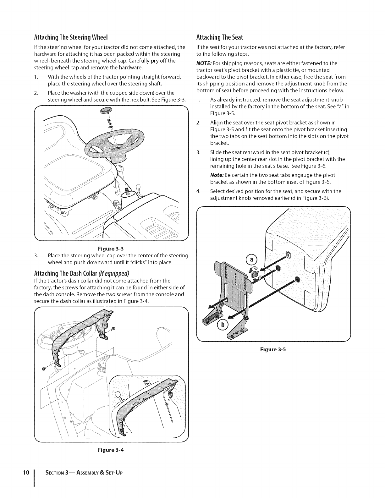
Attaching The Seat
If the seat for your tractor was not attached at the factory, refer
to the following steps.
NOTE: For shipping reasons, seats are either fastened to the
tractor seat's pivot bracket with a plastic tie, or mounted
backward to the pivot bracket. In either case, free the seat from
its shipping position and remove the adjustment knob from the
bottom of seat before proceeding with the instructions below.
1. As already instructed, remove the seat adjustment knob
installed by the factory in the bottom of the seat. See "a" in
Figure 3-5.
2. Align the seat over the seat pivot bracket as shown in
Figure 3-5 and fit the seat onto the pivot bracket inserting
the two tabs on the seat bottom into the slots on the pivot
bracket.
3. Slide the seat rearward in the seat pivot bracket (c),
lining up the center rear slot in the pivot bracket with the
remaining hole in the seat's base. See Figure 3-6.
Note: Be certain the two seat tabs engauge the pivot
bracket as shown in the bottom inset of Figure 3-6.
4. Select desired position for the seat, and secure with the
adjustment knob removed earlier (d in F gure 3-6).
Figure 3-3
3. Place the steering wheel cap over the center of the steering
wheel and push downward until it "clicks" into place.
Attaching TheDashCollarCIfequipped)
If the tractor's dash collar did not come attached from the
factory, the screws for attaching it can be found in either side of
the dash console. Remove the two screws from the console and
secure the dash collar as illustrated in Figure 3-4.
®
Figure 3-5
\ \
Figure 3-4
J
SECTION 3-- ASSEMBLY& SET-UP
Loading ...
Loading ...
Loading ...