

OPERATOR’S MANUAL
80V BRUSHLESS 16"
STRING TRIMMER
267-3212/267-3216
2100294VT/2100294VTBT
STB409
To Reduce The Risk Of Injury, User Must Read
CAUTION
And Understand Operator’s Manual. Save These Instructions For
Future Reference.

TABLE OF CONTENTS
Safety Symbols ........................................................................................................... Page 2
Safety Instructions ...................................................................................................... Page 3
Overview ..................................................................................................................... Page 7
............................................................................................................. Page 7
Assembly .................................................................................................................... Page 8
Operation .................................................................................................................. Page 11
Maintenance ............................................................................................................ Page 15
Troubleshooting ........................................................................................................ Page 16
Exploded view ........................................................................................................... Page 18
Note .......................................................................................................................... Page 19
Warranty ................................................................................................................... Page 22

Page 2
SAFETY SYMBOLS
Some of the following symbols may be used on this product. Please study them and learn their
meaning. Proper interpretation of these symbols will allow you to operate the product better
and safer.
Symbol Name Designation / Explanation
V Volts Voltage
A Amperes Current
Hz Hertz Frequency (cycles per second)
W Watts Power
min Minutes Time
Alternating Current Type of current
Direct Current Type or a characteristic of current
Class II Construction Double-insulated construction.
/min Per Minute
Revolutions, strokes, surface speed, orbits etc.,
per minute
Safety Alert Precautions that involve your safety.
Read The Operator’s Manual
To reduce the risk of injury user must read and
understand operator’s manual before using this
product.
Eye Protection
Always wear eye protection with side shields
marked to comply with ANSI Z87.1 when
operating this equipment.
Wet Conditions Alert
Do not expose the product to rain or moist
conditions.
Ricochet
Thrown objects can ricochet and result in
personal injury or property damage.
No Blade
Do not install or use any type of blade on a
product displaying this symbol.
Keep Bystanders Away Keep all bystanders at least 50 ft. (15m) away.
Page 3
SAFETY INSTRUCTIONS
The purpose of safety symbols is to attract our attention to possible dangers. The safety
symbols, and the explanations with them, deserve your careful attention and understanding.
The symbol warnings do not by themselves eliminate any danger. The instructions and
warnings they give are no substitutes for proper accident prevention measures.
Failure to obey this safety warning CAN result in death or serious
injury to yourself or to others. Always follow the safety precautions to reduce the risk of
WARNING
Failure to obey this safety warning MAY result in personal injury
to yourself or others or property damage. Always follow the safety precautions to
CAUTION
Failure to obey this warning WILL result in death or serious injury
electric shock and personal injury.
DANGER
Be sure to read and understand all safety instructions in this
WARNING
SYMBOL MEANING
SAFETY ALERT SYMBOL: Indicates DANGER, WARNING, OR CAUTION. May be used
in conjunction with other symbols or pictographs.

Page 4
SAFETY INSTRUCTIONS
IMPORTANT SAFETY
INSTRUCTIONS
READ ALL INSTRUCTIONS
BEFORE USING (THIS POWER
TOOL)
WARNING
Read and
understand all instructions before using
this product. Failure to follow all
instructions listed below may result in
personal injury. When using an electrical
following:
• Do not operate power tools in explosive
atmospheres, such as in the presence of
flammable liquids, gases, or dust. Power
tools create sparks that may ignite the dust
or fumes.
• D o n o t all ow c h i l d r e n o r u n t r a i n e d
individuals to use this unit.
• Don’t expose power tools to rain or wet
conditions. Water entering a power tool will
increase the risk of electric shock.
• Do not handle battery or tool with wet
hands.
• Nev er allow c hil dren to o perate th e
equipment. Never allow adults to operate
the equipment without proper instruction.
• Always wear safety glasses with side
shields that are marked to comply with
ANSI Z87.1. Everyday glasses have only
impact resistant lenses. They are NOT
safet y glasses. Following this rule will
reduce the risk of eye injury. Use face
mask if operation is dusty.
• Don’t use in the rain. Store indoors.
• Do not operate in poor lighting.
• Keep all parts of your body away from any
moving part.
• Prevent unintentional starting. Ensure
the switch is in the off-position before
connecting to battery pack, picking up
or carrying the appliance. Carrying the
energizing appliance that have the switch
on invites accidents.
• Do not force tool. Use the correct tool
for your application. The correct tool will
do the job better and safer at the rate for
which it is designed.
• Do not operate the equipment while bare
foot or when wearing sandals or similar
lightweight footwear. Wear protective
footwear that will protect your feet and
improve your footing on slippery surfaces.
• Keep firm footing and balance. Do not
overreach. Overreaching can result in loss
of balance.
• Check Damaged Parts – Before further use
of the appliance, a guard or other part that
is damaged should be carefully checked to
determine that it will operate properly and
perform its intended function.
• Check for alignment of moving parts,
binding of moving parts, breakage of parts,
mounting and any other condition that
may affect its operation. A guard or other
part that is damaged should, be properly
repaired or replaced by an authorized
service center unless indicated elsewhere
in this manual.
• Keep guards in place and in working order.
• Keep hands and feet away from cutting
area.
• Do not allow to be used as a toy. Close
attention is necessary when used by or
near children.
• Do not use tool if switch does not turn it on
or off. Any tool that cannot be controlled
with the switch is dangerous and must be
repaired.
• Keep all bystanders, children, and pets at
least 50 ft. away.
• Do not operate this unit when you are tired,
or medication.
• Use only Masterforce Batteries: BAB726,
BAB727, BAB728, BAB729 and other BAB
series batteries.
• Use only Masterforce Charger: CAB809 or
other CAB series.
• Do not put any object into openings. Do not
use with any opening blocked; keep openings
free.
• Check the work area before each use.
Remove all objects such as rocks, broken
glass, nails, wire, or string which can be
thrown or become entangled in the machine.

Page 5
• Use only identical manufacturer’s replacement
parts and accessories. Use of any other
parts may create a hazard or cause product
damage.
• Do not charge battery in the rain, or damp or
wet locations. Following this rule will reduce
the risk of electric shock.
• For household use only.
• Battery tools do not have to be plugged into
an electrical outlet; therefore, they are always
in operating condition. Be aware of possible
hazards when not using your battery tool or
when changing accessories. Following this
or serious personal injury.
• Remove or disconnect battery before
servicing, cleaning or removing material from
the gardening appliance.
• Use appliance only with specially designated
battery packs. Use of any other battery packs
• Store idle appliances - When not in use, the
string trimmer should be stored indoors in a
dry, locked place out of the reach of children.
•
may explode. Check with local codes for
possible special disposal instructions.
• Do not open or mutilate the batteries.
Released electrolyte is corrosive and may
cause damages to the eyes or skin. It may be
toxic if swallowed.
• Do not place battery tools or their batteries
near fire or heat. This will reduce the risk of
explosion and possibly injury.
• Batteries can explode in the presence of
a source of ignition, such as pilot light. To
reduce the risk of serious personal injury,
never use any cordless product in the
presence of an open flame. An exploded
battery can propel debris and chemicals. If
• Do not crush, drop or damage battery.
Do not use a battery or charger that has
been dropped or received a sharp blow. A
damaged battery is subject to explosion.
Properly dispose of a dropped or damaged
battery immediately.
• Exercise care in handling batteries in order
not to short the battery with conducting
materials such as rings, bracelets, and keys.
The battery or conductor may overheat and
cause burns.
• Under extreme usage or temperature
conditions, battery leakage may occur.
If liquid comes in contact with your skin,
SAFETY INSTRUCTIONS
wash immediately with soap and water,
then neutralize with lemon juice or vinegar.
If liquid gets into your eyes, flush them with
clean water for at least 10 minutes, then seek
immediate medical attention. Following this
rule will reduce the risk of serious personal
injury.
• If the charger power supply cord is damaged,
it must be replaced only by the manufacturer
or by an authorized service center to avoid
risk.
• Do not point the string trimmer in the direction
of people or pets.
• When not in use, the string trimmer should be
stored indoors in a dry, locked up place out of
the reach of children.
• Maintain tool with care. Keep all vents and
openings clean and clear of debris. Follow
instructions for proper maintenance. Do not
switching it off and removing the battery.
• Dress Properly – D o not wear loos e
clothing or jewelry. They can be caught in
moving parts. Use of rubber gloves and
substantial footwear is recommended
when working outdoors. Wear protective
hair covering to contain long hair.
• Use the Correct Appliance – Do not use
appliance for any job except that for which
it is intended.
• When battery pack is not in use, keep it
away from other metal objects like paper
clips, coins, keys, nails, screws or other
small metal objec ts that c an make a
connection from one terminal to another.
• Shorting the battery terminals together
• Do not expose a battery pack or appliance
to fire or temperature above 265°F may
cause explosion.
• Follow all charging instructions and do
not charge the battery pack or appliance
in the instructions. Charging improperly or
at temperatures outside of the specified
ran g e may d am ag e the b at ter y an d
• Have servicing performed by a qualified
r e p a i r p e r so n u s i ng o n l y i d e nt i c a l
replacement parts. This will ensure that the
safety of the product is maintained.
• D o n ot m o d i f y o r a t te m p t t o r e p a ir
the appliance or the bat ter y pack (as
applicable) except as indicated in the

Page 6
SAFETY INSTRUCTIONS
instructions for use and care.
PROPOSITION 65
This product contains a chemical known to
the state of California to cause cancer, birth
defects or other reproductive harm. Some dust
created by power sanding, sawing, grinding,
drilling, and other construction activities
contains chemicals known to cause cancer,
birth defects or other reproductive harm. Some
examples of these chemicals are:
• Lead from lead-based paints;
• Crystalline silica from bricks and cement
and other masonry products;
• Arsenic and chromium from chemically
treated lumber.
Your risk of exposure to these chemicals
varies depending on how often you do this
type of work. To reduce your exposure to these
chemicals, work in a well-ventilated area, and
work with approved safety equipment, such as
out microscopic particles.
CHILD SAFETY
Tragic accidents can occur if the operator is
not aware of the presence of children.
• Keep c hild ren o ut of the wor k ing
area and under the watchful care of a
responsible adult.
• Do not allow children under the age
of 14 to operate this trimmer. Children
who are 14 years of age or older must
read and understand the operating
instructions and safety rules in this
ma nu al a n d m u st be t r ai ned a nd
supervised by a parent.
• Stay alert and turn the trimmer off if a
child or any other person enters the
working area.
• Lo o k beh i n d and d ow n f o r s m al l
chil dre n b efore and w hi le c ut tin g
backwards.
• Use extreme care when approaching
blind corners, doorways, shrubs, trees,
or other objects that may obscure your
view of a child who may run into the
path of the trimmer.
SAVE THESE INSTRUCTIONS
Page 7
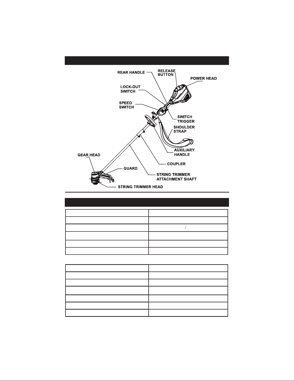
OVERVIEW
SPECIFICATIONS
Type Cordless, battery operated
Motor 80V Brushless
String Cutting Width
14 16 in.
Line Diameter 0.095" / 0.080" (2.4 mm / 2.0 mm)
Speed 6000 / 5000 RPM
Weight (Without Battery) 8 lbs (3.6 kg)
The recommended ambient temperature range:
Item Temperature
String trimmer storage temperature range 32°F (0°C) - 113°F (45°C)
String trimmer operation temperature range 32°F (0°C) - 113°F (45°C)
Battery charging temperature range 39°F (4°C) - 104°F (40°C)
Charger operation temperature range 39°F (4°C) - 104°F (40°C)
Battery storage temperature range 32°F (0°C) - 113°F (45°C)
Battery discharging temperature range 32°F (0°C) - 113°F (45°C)
Page 8
ASSEMBLY
Read and under
stand entire Operator’s M
anual for each
optional attachment used on this power
head and follow all warnings and instructions.
Failure to follow all instructions may result in
electric shock, fire and/or serious personal
injury.
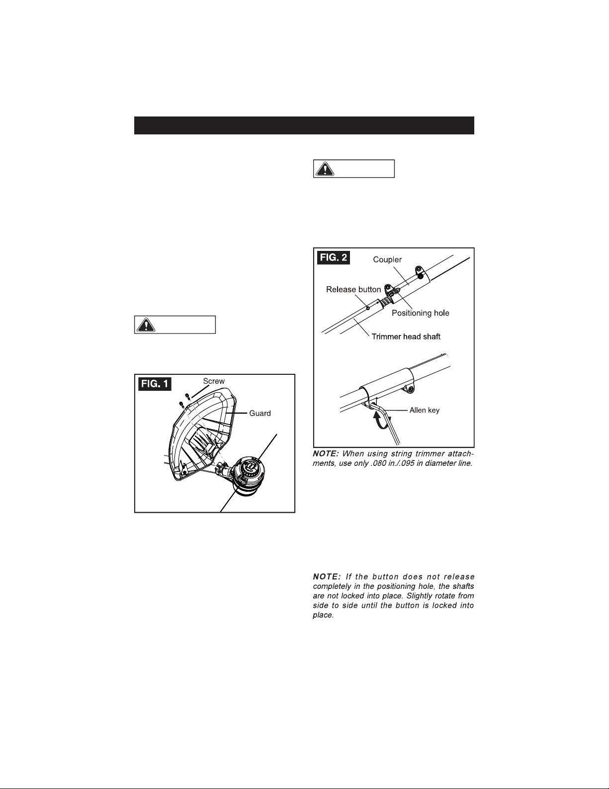
The trimmer head shaft connects to the
power head by means of a coupler device.
1. Loosen the screw on the coupler.
2. Push in the release button located on the
trimmer head shaft. Align the button with
the guide recess on the power head coupler
and slide the two shafts together. Rotate
the trimmer head shaft until the button locks
into the positioning hole.
3. Tighten the attachment screw with the
Allen key (included) securely.
ASSEMBLY
UNPACKING
This product requires assembly.
• Carefully remove the product and any
accessories from the box.
• Inspect the product carefully to make sure
no breakage or damage occurred during
shipping.
• Do not discard the packing material
until you have carefully inspected and
satisfactorily operated the product.
• If any parts are damaged or missing, please
call 1-844-MSTR4CE (844-678-7423) for
assistance.
GUARD
WARNING
To prevent accidental
starting that could cause serious personal
injury, always remove the battery pack from
the tool when assembling parts.
1. Remove the battery.
2. Invert the string trimmer to access the string
trimmer head.
3. Using a Allen key (included), remove the
pre-installed screws from the guard plate on
the string trimmer head.
4. Place the guard onto the string trimmer
head and slide the guard onto the head by
following the track on the head.
5. Align the screw holes on the guard with the
screw holes on the string trimmer head.
6. Insert the screws into the string trimmer
head, fastening the guard in place.
WARNING
Page 9
ASSEMBLY
LINE TRIMMER CUT-OFF BLADE
The trimmer is equipped with a line trimming
cut-off blade on the guard. Replace the line
maintain best performance.
Adjusting the cutting swath
The trimmer is currently set at a 14 in. cutting
swath. To adjust to a cutting swath of 16 in.:
1. Remove the battery from the string
trimmer.
2. Remove both screws from the cut-off
blade with a Phillips screwdriver (not
included).
3. Rotate the cut-off blade 180°.
4. Replace both screws in the cut-off blade.
AUXILIARY HANDLE
1. Remove the knob from the handle.
2. Attach the auxiliary handle and lower
clamp on the shaft.
3. Set the auxiliary handle to a comfortable
position.
4. Put the bolt through the holes.
5. Tighten the auxiliary handle with the
knob.
FIG. 4
FIG. 3
Page 10
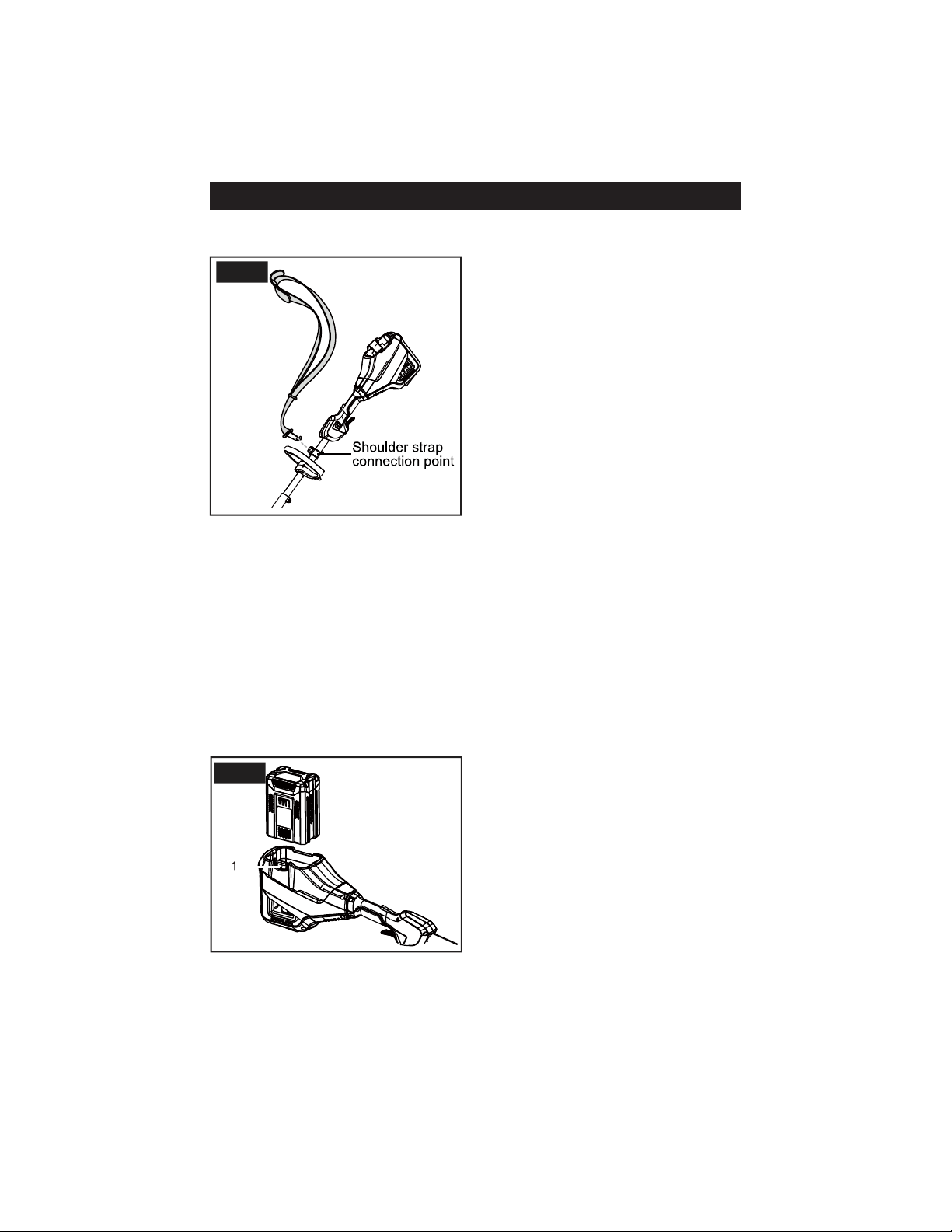
ASSEMBLY
SHOULDER STRAP
1. Rotate the shoulder strap connection point
to the upward position.
2. Hook the shoulder strap to the shoulder
strap connection point.
THE BATTERY PACK
• If the battery pack or charger is damaged,
replace the battery pack or the charger.
• Stop the machine and wait until the motor
stops before you install or remove the battery
pack.
• Read, know, and follow the instructions in
the battery and charger manuals.
To install the battery pack
1. Align the lift ribs on the battery pack with
the grooves in the battery compartment.
2. Push the battery pack into the battery
compartment until the battery pack locks
into place.
3. When you hear a click, the battery pack is
installed.
To remove the battery pack
1. Push and hold the battery release button
(1).
2. Remove the battery pack from the
machine.
FIG. 6
FIG. 5
Page 11
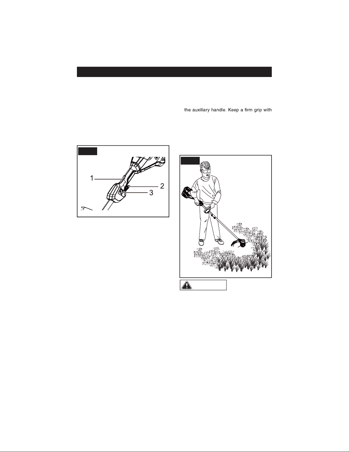
LOCK-OUT SWITCH
The lock-out switch reduces the possibility
of accidental starting. The lock-out switch is
located on the handle above the switch trig-
ger. The lock-out switch must be depressed
before you pull the switch trigger. The lock
resets each time the trigger is released.
START / STOP THE TRIMMER
1. Ensure a fully charged battery is installed
into the string trimmer.
2. To start the string trimmer, press and hold
the lock-out switch (1) and squeeze the
switch trigger (2).
3. Push the speed switch (3) to the desired
operating speed. Push the speed switch
to position 1 for low speed or position 2 for
high speed.
OPERATION TIPS
• Hold the string trimmer with your right hand
on the rear handle and your left hand on
both hands while in operation. Power head
should be held at a comfortable position
with the rear handle about hip height.
• Always operate power head at full throttle.
If debris becomes wrapped around the
string trimmer head, release the switch
trigger, and remove the debris.
Any contact with the cutting head can result
in burns and/or other serious personal injury.
Never use a brush cutter head with this
trimmer.
OPERATION
WARNING
FIG. 1
FIG. 2
Page 12
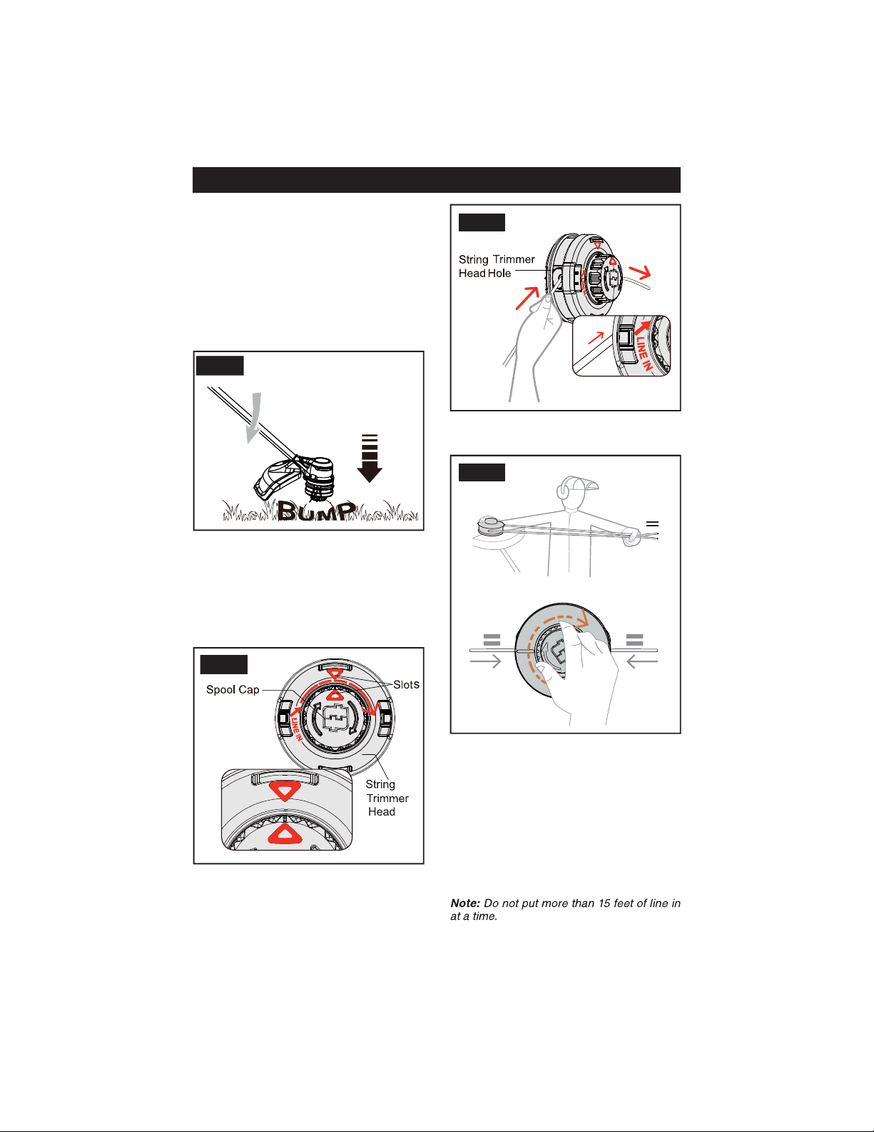
ADJUST THE LENGTH OF THE
CUTTING LINE
While you operate the machine, the cutting
line gets worn shorter. You can adjust the
length of the cutting line.
1. Bump the trimmer head against the ground
while you operate the machine.
2. Line is automatically released and the cut-
off blade cuts the excess length.
INSTALL TRIMMER LINE IN THE
STRING TRIMMER HEAD
1. Line up the slots on the spool cap with the
slots on the string trimmer head.
OPERATION
FIG. 3
FIG. 4
2. Insert 15 feet or less of trimmer line through
the string trimmer head hole. Push line until
it exits through the opposite hole.
3. Pull the line through until there is an equal
amount of line on each side of the string
trimmer head.
4. Turn the spool cap clockwise to begin
winding the line into the string trimmer
head. Leave approximately 5 inches of line
protruding out of each side of the head.
It is recommended that 0.080"/0.095"
diameter line be used for this string trimmer
head.
FIG. 5
FIG. 6
Page 13
CLEANING DEBRIS AND
OBSTRUCTIONS FROM THE
STRING TRIMMER HEAD
1. Remove the battery pack.
2. Firmly press in the tabs on each side of the
spool cover.
3. Remove the spool cover from the spool
housing.
4. Remove any excess trimmer line or
obstructions from the spool.
5. Use a clean cloth to wipe away any debris
from the spool, spool cover, or spool
housing.
6. Align the tabs of the spool cover with the
posts on the spool housing. Push the spool
cover until the tabs securely snap into the
posts.
7. Replace the battery pack.
OPERATION
FIG. 7
FIG. 8
FIG. 9
Page 14
OPERATION
REMOVE THE STRING TRIMMER
HEAD OR RE-INSTALLING TRIM-
MER HEAD
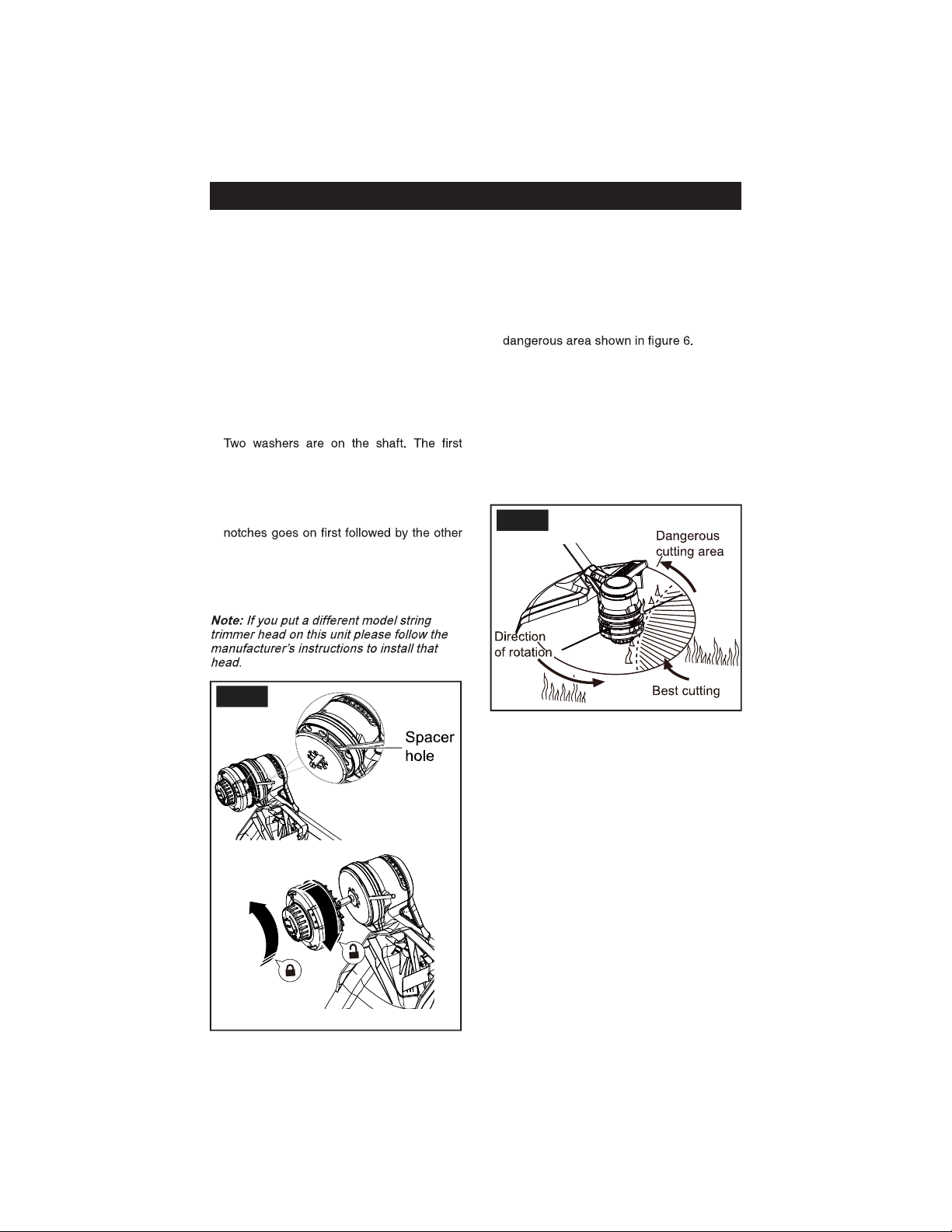
1. Line up the spacer hole up with the hole in
the gear box.
2. Place a small screwdriver or metal rod (not
included) in the spacer hole. Rotate the head
until the metal rod or screwdriver drops into
a notch. Keep the rod or screwdriver in this
notch, it will hold the trimmer head still so it
can be unscrewed from the shaft.
3. Rotate the head clockwise to unscrew the
trimmer head, removing it.
4.
washer covers the shaft opening. Behind it,
is a smaller washer with sprocket notches
cut on the inner edge. If these washers fall
off while removing the trimmer head make
sure the smaller washer with sprocket
washer when replacing the trimmer head or
installing a new head.
5. Reverse steps 1-3 to reinstall the same
string trimmer head.
CUTTING TIPS
• Keep the trimmer tilted toward the area
being cut; this is the best cutting area.
• The trimmer cuts when moving the unit
from right to left. This will avoid throwing
debris at the operator. Avoid cutting in the
• Use the tip of trimmer line to do the cutting;
do not force string trimmer head into uncut
grass.
• Wire and picket fences cause extra trimmer
line wear and breakage. Stone and brick
walls, curbs, and wood may wear trimmer
line rapidly.
• Avoid trees and shrubs. Tree bark, wood
moldings, siding, and fence posts can
easily be damaged by the trimmer line.
FIG.10
FIG.11
Page 15
MAINTENANCE
When servicing,
use only identical replacement parts. Use
of any other parts may create a hazard or
cause product damage.
Before inspecting, cleaning, or servicing the
machine, shut off motor, wait for all moving
parts to stop, and disconnect battery. Failure
to follow these instructions can result in
serious personal injury or property damage.
GENERAL MAINTENANCE
Avoid using solvents when cleaning plastic
parts. Most plastics are susceptible to
damage from various types of commercial
solvents and may be damaged by their
use. Use clean cloths to remove dirt, dust,
lubricant, grease, etc.
Do not at any
time let brake
penetrating lubricants, etc.,
come in contact with plastic parts.
Chemicals can damage, weaken or destroy
plastic which may result in serious personal
injury.
You can often make adjustments and repairs
described here. For other repairs, have
the power head serviced by an authorized
service dealer.
CLEANING THE POWER HEAD
• Stop the motor and remove the battery.
• Clean dirt and debris from the power head
using a damp cloth with a mild detergent.
STORING THE POWER HEAD
• Clean all foreign material from the product.
• Store it in a well-ventilated place that is
inaccessible to children.
• Keep away from corrosive agents such as
garden chemicals and de-icing salts.
Do not store the
string trimmer in sunlight, in an excessively
warm place, or near a furnace. The battery
life will be shortened.
WARNING
WARNING
WARNING

Page 16
PROBLEM POSSIBLE CAUSE SOLUTION
The machine does not
start when you push
the trigger.
No electrical contact
between the machine
and the battery pack.
1. Remove battery pack.
2. Check contact and install the battery pack
again.
The battery pack is
depleted.
Charge the battery pack.
The lock-out switch
and trigger are not
pushed at the same
time.
1. Push the lock-out switch and hold it.
2. Pull the trigger to start the machine.
The machine stops
when you cut.
The guard is not
attached to the
machine.
Remove the battery pack and attach the guard
to the machine.
Heavy cutting line is
used.
Use only with nylon cutting line up to 0.095"
(2.4 mm) diameter.
The grass winds
around the motor
shaft or the trimmer
head.
1. Stop the machine.
2. Remove the battery pack.
3. Remove the grass from the motor shaft and
trimmer head.
The motor is
overloaded.
1. Remove the trimmer head from the grass.
2. The motor will recover to work as soon as
the load is removed.
3. When you cut, move the trimmer head in and
out of the grass to be cut and remove no more
than 8" in each pass.
The battery pack or
machine is too hot.
1. Cool the battery pack until its function returns
to normal.
2. Cool the machine for approximately 10
minutes.
The battery pack is
disconnected from
the tool.
Install the battery pack again.
The battery pack is
depleted.
Charge the battery pack.
The line does not
advance.
Not enough line on
spool.
Install more line.
Lines are worn too
short.
Advance the cutting line.
Lines are tangled on
spool.
1. Remove the lines from the spool.
2. Wind the lines.
TROUBLESHOOTING

Page 17
The line keeps
breaking.
The machine is used
incorrectly.
1. Cut with the tip of the line, avoid stones,
walls and other hard objects.
2. Advance the cutting line regularly to keep full
cutting width.
The grass winds
around the trimmer
head and motor
housing.
Cut tall grass at
ground level.
1. Cut tall grass from the top down.
2. Remove no more than 8" in each pass to
prevent wrapping.
The line does not cut
well.
The cut-off blade
becomes dull. it.
Vibration increases
noticeably.
The line is worn down
on one side and not
the other.
Make sure that the line on both sides is normal.
Advance the line.
TROUBLESHOOTING
Page 18
ITEM NO. PART NO. DESCRIPTION QTY
1
R0202489-00 Auxiliary handle assembly 1
1.1
R0201826-00 Bollt 1
1.2
R0201827-00 Auxiliary handle 1
1.3
R0201828-00 Lower clamp 1
1.4
R0202482-00 Knob 1
2
RB37902144 Shoulder strap 1
3
R0202483-00 Trimmer head assembly 1
4
R0202484-00 Guard assembly 1
5
R0202485-00 Coupler screw 1
6
R0201770-00 Allen key 1

Page 19
NOTE

Page 20
NOTE

Page 21
NOTE

SAVE YOUR RECEIPTS
THIS WARRANTY IS VOID WITHOUT THEM
80V BRUSHLESS 16" STRING TRIMMER
WARRANTY
4-YEAR LIMITED WARRANTY
This MASTERFORCE™ brand power tool carries our famous No Hassle 4-Year Limited
Warranty to the original purchaser. If, during normal use, this MASTERFORCE™ power
tool breaks or fails due to a defect in material or workmanship within four (4) years from
the date of original purchase, simply bring the tool with the original sales receipt back
to your nearest MENARDS
®
retail store. At its discretion, MASTERFORCE™ agrees
to have the tool or any defective part(s) repaired or replaced with the same or similar
MASTERFORCE™ product or part free of charge, within the stated warranty period,
when returned by the original purchaser with original sales receipt. Not withstanding the
foregoing, this limited warranty does not cover any damage that has resulted from abuse
or misuse of the Merchandise. This warranty: (1) excludes expendable parts including
but not limited to blades, brushes, belts, bits, light bulbs, and/or batteries; (2) shall be
void if this tool is used for commercial and/or rental purposes; and (3) does not cover any
losses, injuries to persons/property or costs. This warranty does give you specific legal
rights and you may have other rights, which vary from state to state. Be careful, tools
are dangerous if improperly used or maintained. Seller’s employees are not qualified
to advise you on the use of this merchandise. Any oral representation(s) made will not
be binding on seller or its employees. The rights under this limited warranty are to the
original purchaser of the merchandise and may not be transferred to any subsequent
owner. This limited warranty is in lieu of all warranties, expressed or implied including
warranties or merchantability and fitness for a particular purpose. Seller shall not be
liable for any special, incidental, or consequential damages. The sole exclusive remedy
against the seller will be for the replacement of any defects as provided herein, as long
as the seller is willing or able to replace this product or is willing to refund the purchase
price as provided above. For insurance purposes seller is not allowed to demonstrate
any of these power tools for you.
For questions / comments, technical assistance or repair parts -
Please call toll free at: 1-844-678-7423 (M-F 8am - 6pm)
Page 22

Page 23
© 2020 Menard, Inc., Eau Claire, WI 54703 12/2020