Loading ...
Loading ...
Loading ...
4
LIFT LEVER
ASSEMBLY
SLEEVE HITCH
FRAME ASSEMBLY
SHOULDER
BOLT
5/8" NYLOCK NUT
(H)
HEX BOLT
5/8" x 1-3/4"
(B)
Lift ASSembLy
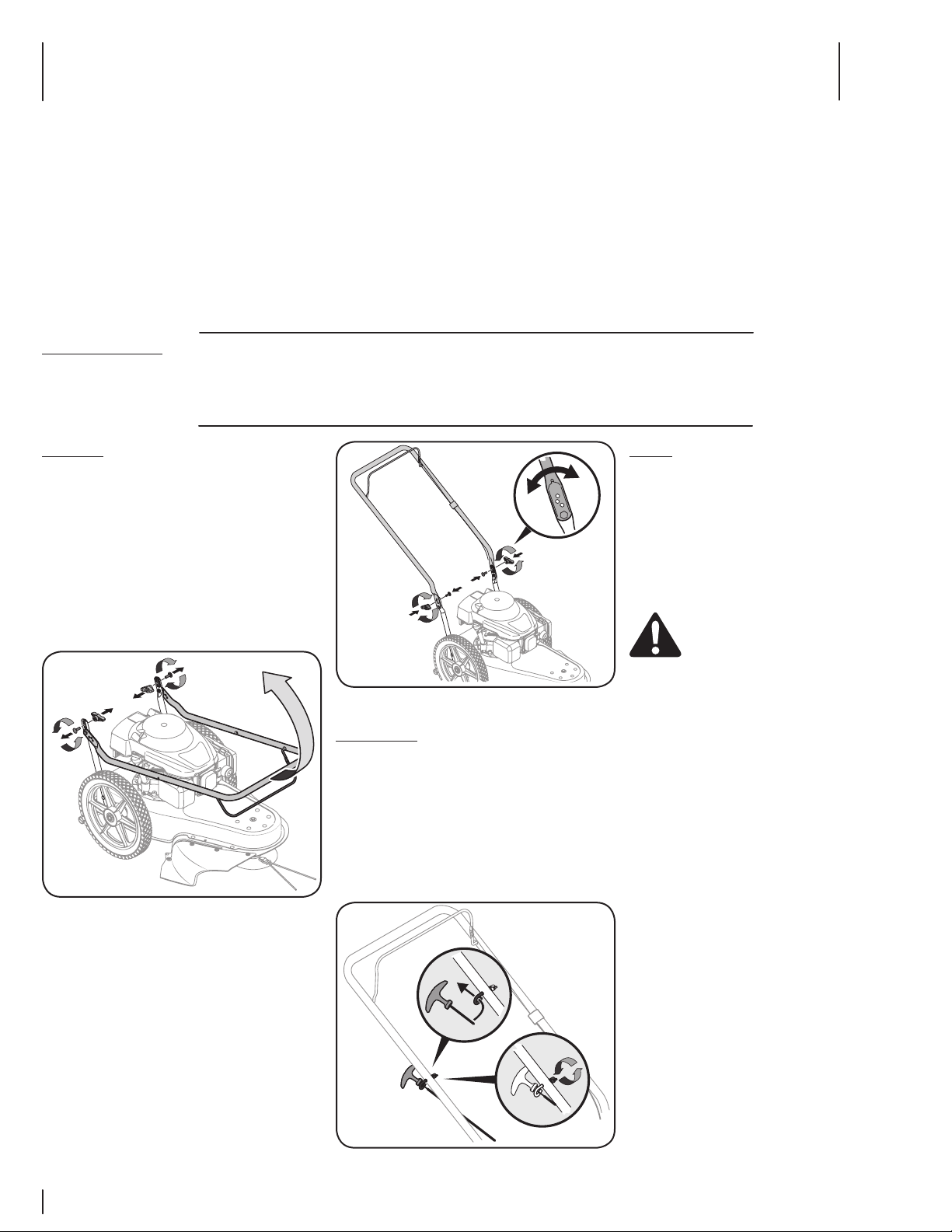
Step 1: (fig. 1)
1. Assemble the two 5/8" jam nuts (G) halfway onto the
two 5/8" x 2" hex bolts (A). Screw the bolts into the
nuts that are welded to the Sleeve Hitch Lift Assembly.
Tighten the jam nuts against the welded nuts.
2. Assemble the Lifting Link to the Sleeve Hitch Lift
Assembly using a 5/8" x 1-3/4" hex bolt (B) and a 5/8"
nylock nut (H). Use the bottom hole in the Lifting Link
(gives the lowest implement depth setting). Tighten
the nut only until snug. Do not squeeze welded arms
together.
Step 2: (fig. 2)
1. Attach the Sleeve Hitch Lift Assembly to the Sleeve
Hitch Frame Assembly using three 5/8" x 1-3/4" clevis
pins (F) and 3/32" hair cotter pins (P).
2. Install the Hitch Pin in the sleeve hitch and secure it with
the 5/32" hair cotter pin (Q).
Fig.2
Fig.1
5/8"x 2"
HEX BOLT
(A)
5/8" NYLOCK NUT
(H)
5/8" JAM NUT
(G)
5/8"x 1-3/4"
HEX BOLT
(B)
LIFTING LINK
(3) 3/32" HAIR
COTTER PINS
(P)
5/32" HAIR
COTTER PIN
(Q)
HITCH PIN
(3) CLEVIS PINS
(F)
Fig.4
Step 5
1. Proceed to LIFT ASSEMBLY instructions.
247 ASSembLy
Step 4: (fig. 4)
1. Hook the Sleeve Hitch Frame assembly onto the
shoulder bolts of the tractor frame. Attach the bottom
of the assembly to the tractor hitch using a 5/8" x 1-34"
hex bolt (B) and a 5/8" nylock nut (H).
Step 5
1. Proceed to LIFT ASSEMBLY instructions.
LIFT LEVER
ASSEMBLY
SLEEVE HITCH
FRAME ASSEMBLY
SHOULDER
BOLT
5/8" NYLOCK NUT
(H)
HEX BOLT
5/8" x 1-3/4"
(B)
Cmx ASSembLy
Step 4: (fig. 4)
1. Hook the Sleeve Hitch Frame assembly onto the
shoulder bolts of the tractor frame. Attach the bottom
of the assembly to the tractor hitch using a 5/8" x 1-34"
hex bolt (B) and a 5/8" nylock nut (H).
Fig.4
Loading ...
Loading ...
Loading ...