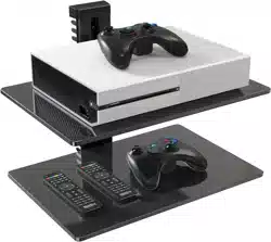
V2.0
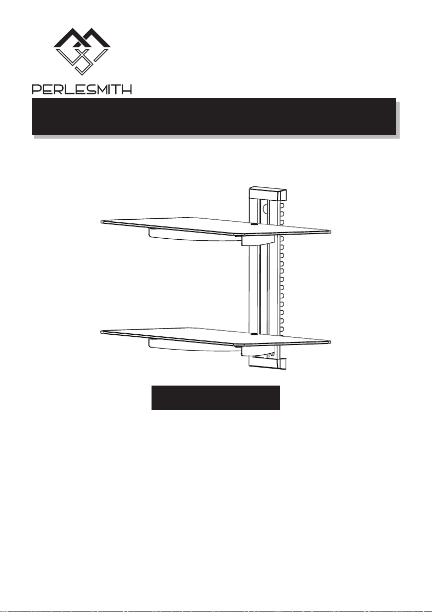
Floating Wall Mounted Shelf Instruction Manual
Model: PSDSK2-1
Thank you for choosing this PERLESMITH product! At
PERLESMITH we strive to provide you with the best quality
products and services in the industry. Should you have any issues,
please don't hesitate to contact us at
Technical Support:
1-800-556-6806 Mon-Fri 8am - 8pm(CST)
Other Info:
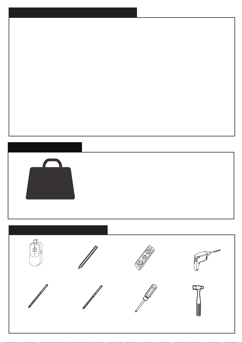
Stud
Finder
Pencil
1/8 in
(3.2 mm)
Wood Drill
Phillips
Screwdriver
Hammer
Level
5/16 in
(8 mm)
Concrete Drill
Drill
CAUTION!
17.6 lbs.
(8 kg)
DO NOT exceed the maximum weight
indicated. This mounting system is intended
for use only within the maximum weights
indicated. Use with products heavier than
the maximum weights indicated may result
in failure of the mount and its accessories,
causing damage and or injury.
*
*
*
*
*
WARNING! SEVERE PERSONAL INJURY AND PROPERTY DAMAGE CAN RESULT FROM IMPROPER
INSTALLATION OR ASSEMBLY. READ THE FOLLOWING WARNINGS BEFORE BEGINNING.
If you do not understand the instructions or have any concerns or questions, please contact us at
[email protected] (US)/[email protected] (CA).
Do not install or assemble if the product or hardware is damaged or missing. Not all parts and
hardware included must be used. If you require replacement parts, contact customer service at
[email protected] (US)/[email protected] (CA).
Do not attempt to install or assemble this product if the product or hardware is damaged or missing.
The included hardware is designed for use on vertical walls constructed of wood studs or concrete. A
wood stud wall is defined as consisting of a minimum of 2x4 wooden studs (2” width by 4” depth)
with a maximum of 5/8” drywall. The included hardware is not designed for use with metal studs or
drywall. If you’re uncertain about the construction of your wall, then please consult a qualified
contractor or installer for assistance.
For a safe installation, the wall you are mounting to must support 4 times the weight of the total
load. If not, then the surface must be reinforced to meet this standard. The installer is responsible for
verifying that the wall structure and hardware used in any installation method will safely support the
total load.
Weight Restrictions
Tools Needed (Not lncluded)
11
IMPORTANT SAFETY INFORMATION
WARNING:
● Any material covering the wall must not exceed 5/8 in (16 mm).
● Nominal wood stud size: common 2 x 4 in (51 x 102 mm) minimum
1½ x 3½ in (38 x 89 mm).
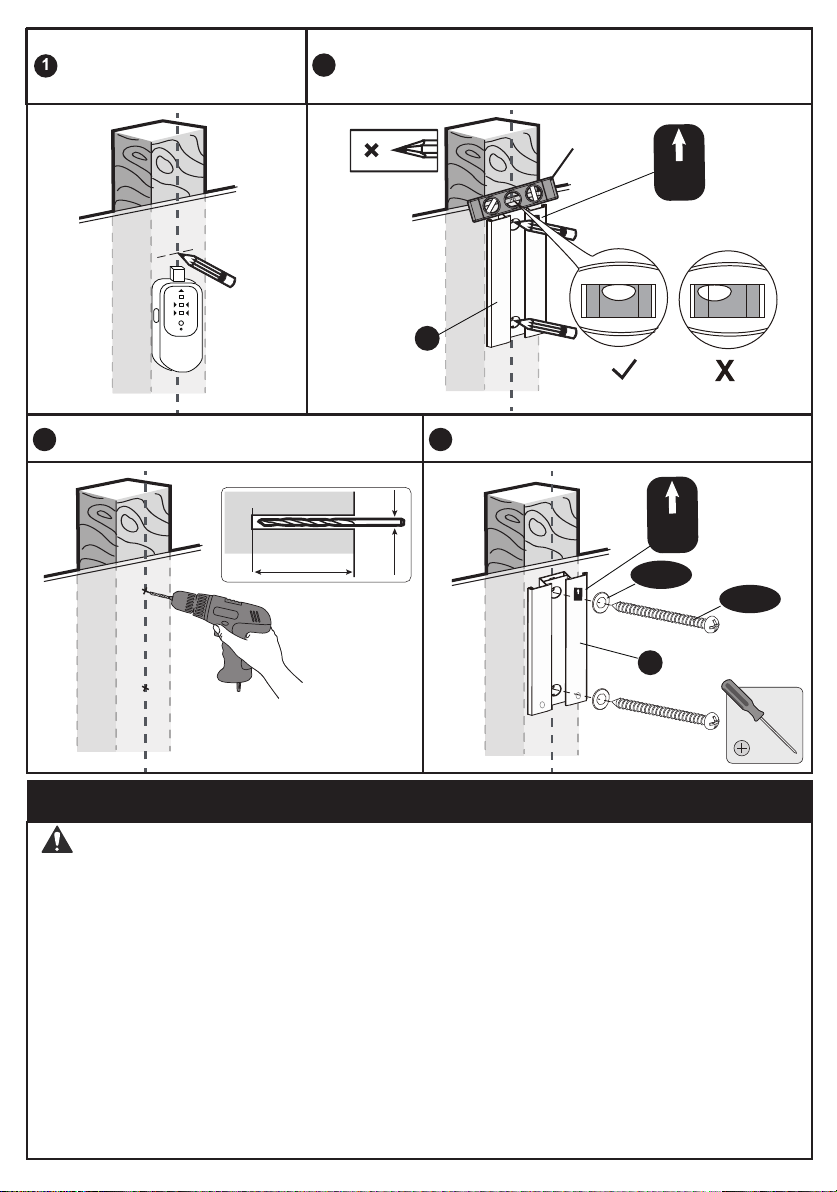
● Stud center must be verified.
1a MOUNT WALL PLATE ON WOOD STUD WALL
● DO NOT USE ANCHOR [W-B] FOR THIS STEP!
● Avoid potential personal injury or property damage! DO NOT over-tighten the
lag screws [W-A-1]. Tighten the lag screws [W-A-1] only until the washers
[W-A-2] are pulled firmly against the wall plate.
● Ensure the wall plate [A] is securely fastened to the wall before
continuing to the next step.
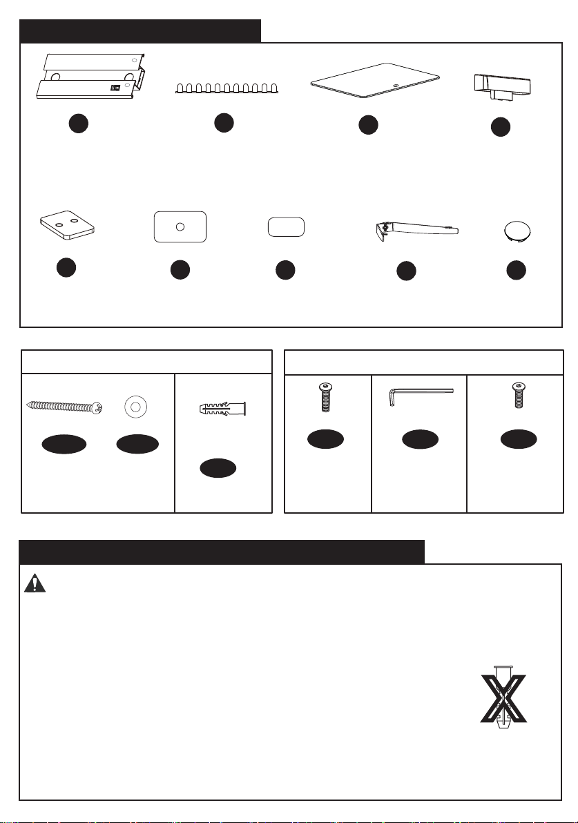
D
C
B
A
X1
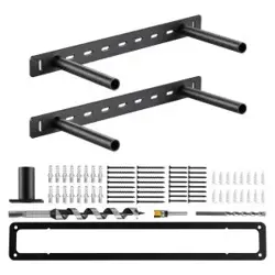
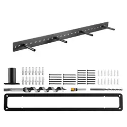
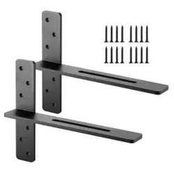
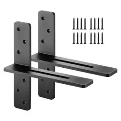
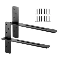
Glass Shelf Support
G
X2
Plug
H
Connector
E
X4 X2 X2
X2 X2 X2X4
Pad Pad
F1
W-A-1
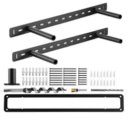
Shelf Kits
Wall Kits
Bolt
M5x8mm
Allen Key
x1
x2
Lag Screw
Cable manager
Wall plate
End cap
Glass shelf
Anchor
S-C
S-B
x4
x2
S-A
Bolt
M5x10mm
x2
Washer
W-B
F2
Supplied Parts and Hardware
2
W-A-2
M8X40mm
x2
ST5.5x50mm
X
WARNING:
Use a stud finder to locate
wood stud and mark the edge
and center location.
Position the wall plate [A] at your desired height and line up
the holes with your stud center line. Level the wall plate and
mark 2 holes.
2
1b. MOUNT WALL PLATE ON CONCRETE BLOCK OR SOLICK BRICK
Drill pilot holes using a 1/8 in (3.2 mm)
diameter drill bit.
Secure the wall plate [A] with the lag
screws [W-A-1] and washers [W-A-2].
3 4
1/8 in
Ø3.2 mm
2.0in (50mm)
3
UP
UP
UP
A
Level
UP
W-A-2
W-A-1
●Avoid potential personal injury or property damage! DO NOT over-tighten the
lag screws [W-A-1]. Tighten the lag screws [W-A-1] only until the washers
[W-A-2] are pulled firmly against the wall plate [A].
●Ensure the wall plate is securely fastened to the wall before continuing to the
next step.
● Any material covering the wall must not exceed 5/8 in (16 mm).
● Mount the wall plate [A] directly onto the concrete surface.
● Minimum solid concrete thickness: 203 mm (8 in).
● Minimum concrete block size: 203 x 203 x 406 mm (8 x 8 x 16 in).
● Never drill into the mortar between blocks.
● CAUTION: Secure the glass shelf to the lower glass shelf support at first, then
secure the topper-shelf.
A
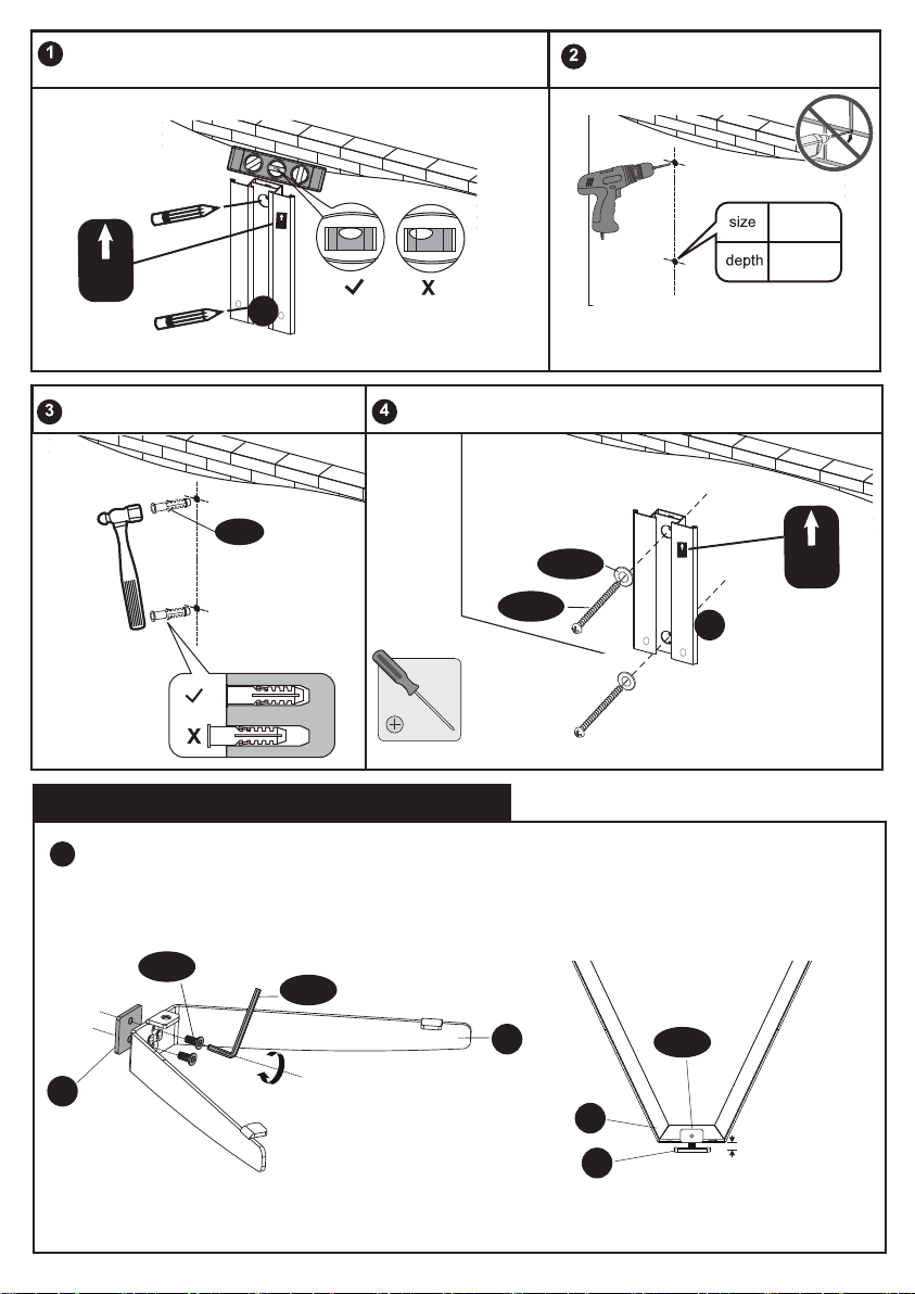
4
Position the wall plate [A] at your desired height, level the wall
plate [A] and mark 2 pilot hole locations.
1/8”
(3.2mm)
2
(60mm)
5/16”
(8mm)
2 3/16”
(55mm)
Drill 2 pilot holes into concrete wall.
A
Knock 2 anchors [W-B] into drilled
holes with hammer.
Secure the wall plate [A] to concrete wall using lag screws
[W-A-1] and washers [W-A-2] by phillips screwdriver.
A
1
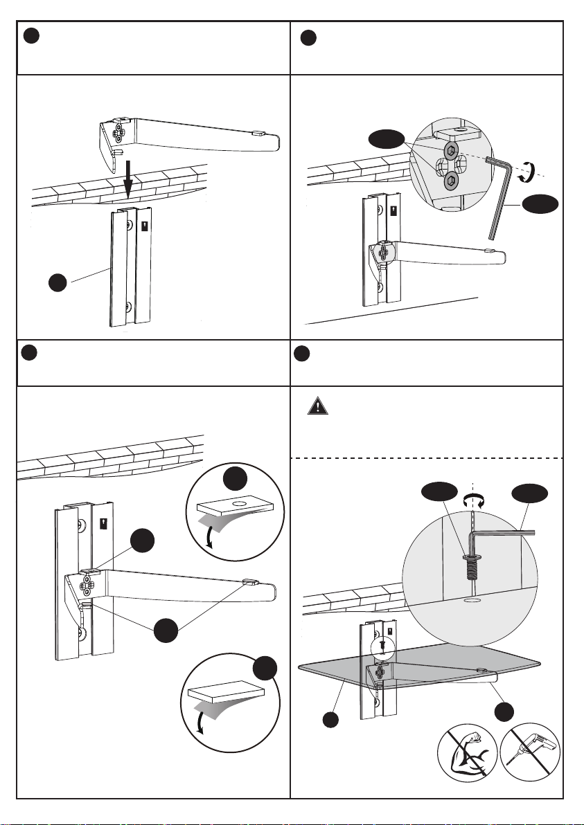
2. INSTALL THE TEMPERED GLASS
G
S-A
E
S-B
UP
UP
UP
UP
1/8 in(3mm)
W-A-1
W-A-2
Connect the connector [E] to glass shelf support [G] with bolts [S-A] and Allen key
[S-B] as shown in the Fig.2.1 and keep about 1/8in(3mm) spacing left between the
connector with glass shelf support as shown in the Fig. 2.2.
W-B
Fig.2.1 Fig.2.2
E
G
S-A
Note: Never drill into the mortar
between blocks
F2
F1
Peel off
F2
Peel off
F1
UP
5
A
Secure glass shelf [C] to glass shelf support
[G].
Paste the pads [F1 and F2] to glass shelf
support [G] respectively.
5
3
4
2
S-B
S-A
Insert the glass shelf support [G] along
the wall plate rail at the desired height
respectively.
Firmly tighten the bolts [S-A] with Allen
key [S-B].
UP
UP
C
G
S-B
S-C
Note: DO NOT overtighten.
Tighten only until snug
Note: The tempered
glass base is designed
to show the shiny
glass side facing up.
UP
CAUTION: Secure the glass shelf to
the lower glass shelf support at first, then secure
the topper-shelf one.
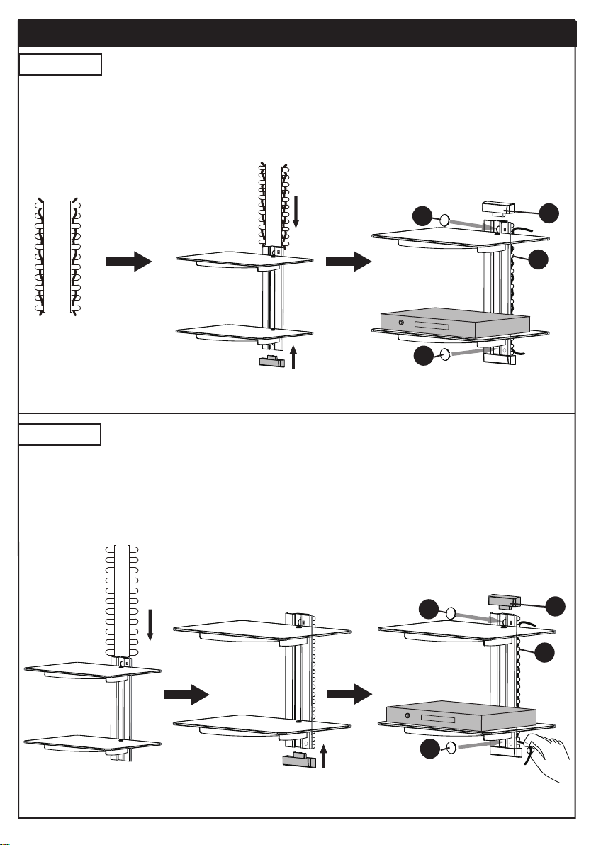
3. ADD END CAPS AND PLUGS
Option A
H
H
D
B
DVD
6
Option B
H
H
D
B
DVD
3B-1 3B-2 3B-3
3B-1 Insert the cable manager with cables into the wall plate
3B-2 Add end caps and plugs into the wall plate
3B-3 Manage the cables along with the cable manager
3A-1 3A-2 3A-3
3A-1 Manage the cables along with the cable manager
3A-2 Add one of the end caps to the bottom of the wall plate, then insert the
cable manager with cables into the wall plate
3A-3 Add end caps and plugs into the wall plate
UP
UP
(Not Included)
(Not Included)
UP
UP
UP
Thank you again
for choosing this PERLESMITH product!
All of us at PERLESMITH do appreciate your product purchase. We hope that you
are as happy with your product as we designing and manufacturing it for you. We
strive to provide you with the best quality products and services in the industry. If
you have any questions please don't hesitate to contact us at
Technical Support:
1-800-556-6806 Mon-Fri 8am - 8pm(CST)
Other Info: