Owner's Manual
CRAFTS[MAN+
16 HP
ELECTRIC START
42" MOWER
6 SPEED TRANSAXLE
LAWN TRACTOR
Model No.
917.271072
i *
• Safety
• Assembly
• Operation
• Maintenance
• Repair Parts
CAUTION:
Read and follow all Safety
Rules and Instructions before
operating this equipment.
For answers toyour questions
about this product, Call:
1-800-659-5917
Sears Craftsman Help Line
5 am - 5 pm, Mon- Sat
Seam, Roebuck and Co., Hoffman Estates, U60179
Visit our Craftsman website:www.sears.com/craftsman
WarranT ...............................................2
Safety Hules ......................................... 2
Product Specifications .......................... 5
Assembly .............................................. 7
Operation ............................................ 10
Maintenance Schedule ...................... 16
Service and Adjustments .................... 20
Storage ............................................... 26
Troubleshooting ................................. 27
Repair Parts ........................................ 32
Parts Ordering ..................... Back Cover
LIMITED TWO YEAR WARRANTY ON CRAFTSMAN RIDING EQUIPMENT
For two (2) years from the date of purchase, if this Craftsman Riding Equipment is
maintained, lubricated and tuned up according to the instructions in the owner's
manual, Sears will repair or replace, free of charge, any parts found to be defective in
material or workmanship.
This Warranty does not cover:
• Expendable items which become worn during normal use, such as blades, spark
plugs, air cleaners, belts, etc.
• Tire replacement or repair caused by punctures from outside objects, such as nails,
thorns, stumps, or glass.
• Repairs necessary because of operator abuse, negligence, improper storage or
accident or the failure to maintain the equipment according to the instructions
contained in the owner's manual.
• Riding equipment used for commercial or rental purposes.
LIMITED 90 DAY WARRANTY ON BATTERY
For ninety (90) days from date of purchase, if any battery included with this riding
equipment proves defective in material or workmanship and our testing determines the
battery will not hold a charge, Sears will replace the battery at no charge. In-home
warranty service on your Craftsman riding equipment is available at no charge for 30
days from the date of purchase. Please contact your nearest service center. After 30
days from the date of purchase, warranty service is available by taking your Craftsman
riding equipment to your nearest Sears Service Center. (In-home warranty service will
still be available after 30 days from the date of purchase but a standard trip charge will
apply). This warranty applies only while this product is in the United States. This
Warranty gives you specific legal rights, and you may also have other rights which may
vary from state to state.
Sears, Roebuck and Co., D/817 WA, Hoffman Estates, tL 60179
IMPORTANT: This cutting machine is
capable of amputating hands and feet
and throwing objects. Failure to observe
the following safety instructions could
result in serious injury or death.
GENERAL OPERATION
• Read, understand, and follow all
instructions in the manual and on the
machine before starting.
• Only allow responsible adults, who are
familiar with the instructions, to
operate the machine.
• Clear the area of objects such as
rocks, toys, wire, etc., which could be
picked up and thrown by the blade.
• Be sure the area is clear of other
people before mowing. Stop machine
if anyone enters the area.
• Never carry passengers.
• Do not mow in reverse unless abso-
lutely necessary. Always look down
and behind before and while backing.
• Be aware of the mower discharge
direction and do not point it at anyone.
Do not operate the mower without
either the entire grass catcher or the
guard in place.
• Slow down before turning.
• Never leave a running machine
unattended. Always turn off blades, set
parking brake, stop engine, and
2 remove keys before dismounting.
• Tum off blades when not mowing.
• Stop engine before removing grass
catcher or unclogging chute.
• Mow only in daylight or good artificial
light.
• Do not operate the machine while
under the influence of alcohol or
drugs.
• Watch for traffic when operating near
or crossing roadways.
• Use extra care when loading or
unloading the machine into a trailer or
truck.
• Data indicates that operators, age 60
years and above, are involved in a
large percentage of riding mower-
related injudes, These operators
should evaluate their ability to operate
the riding mower safely enough to
protect themselves and others from
serious injury.
SLOPE OPERATION
Slopes are a major factor related to loss-
of-control and tipover accidents, which
can result in severe injury or death. All
slopes require extra caution. If you
cannot back up the slope or if you feel
uneasy on it, do not mow it.
DO:
* Mow up and down slopes, not across.
• Remove obstacles such as rocks, tree
limbs, etc.
* Watch for holes, ruts, or bumps.
Uneven terrain could overturn the
machine. Tall grass can hide ob-
stacles.
• Use slow speed. Choose a low gear
so that you will not have to stop or shift
while on the slope,
• Follow the manufacturer's recommen-
dations for wheel weights or counter-
weights to improve stability.
• Use extra care with grass catchers or
other attachments. These can change
the stability of the machine.
• Keep all movement on the slopes slow
and gradual. Do not make sudden
changes in speed or direction.
• Avoid starting or stopping on a slope. If
tires lose traction, disengage the
blades and proceed slowly straight
down the slope.
DO NOT:
• Do not turn on slopes unless neces-
sary, and then, turn slowly and
gradually downhill, if possible.
• Do not mow near drop-offs, ditches, or
embankments. The mower could
suddenly turn over if a wheel is over
the edge of a cliff or ditch, or if an edge
caves in.
• Do not mow on wet grass. Reduced
traction could cause sliding.
• Do not try to stabilize the machine by
putting your foot on the ground.
• Do not use grass catcher on steep
slopes.
CHILDREN
Tragic accidents can occur if the operator
is not alert to the presence of children.
Children are often attracted to the
machine and the mowing activity. Never
assume that children will remain where
you last saw them.
• Keep children out of the mowing area
and under the watchful care of another
responsible adult.
• Be alert and turn machine off if
children enter the area.
• Before and when backing, look behind
and down for small children.
• Never carry children. They may fall off
and be seriously injured or interfere
with safe machine operation.
• Never allow children to operate the
machine.
• Use extra care when approaching
blind corners, shrubs, trees, or other
objects that may obscure vision.
SERVICE
• Use extra care in handling gasoline
and other fuels. They are flammable
andvapors are explosive.
Use only an approved container.
Never remove gas cap or add fuel
with the engine running. Allow en-
gine to cool before refueling. Do
not smoke.
Never refuel the machine indoors.
Never store the machine or fuel
container inside where there is an
open flame, such as a water heat-
er.
• Never run a machine inside a closed
area.
3
• Keep nuts and bolts, especially blade
attachment bolts, tight and keep
equipment in good condition.
• Never tamper with safety devices.
Check their proper operation regularly.
• Keep machine free of grass, leaves, or
other debris build-up. Clean oil or fuel
spillage. Allow machine to cool before
storing.
• Stop and inspect the equipment if you
strike an object. Repair, if necessary,
before restarting.
• Never make adjustments or repairs
with the engine running.
• Grass catcher components are subject
to wear, damage, and deterioration,
which could expose moving parts or
allow objects to be thrown. Frequently
check components and replace with
manufacturer's recommended parts,
when necessary.
• Mower blades are sharp and can cut.
Wrap the blade(s) or wear gloves, and
use extra caution when servicing
them.
• Check brake operation frequently.
Adjust and service as required.
• Be sure the area is clear of other
people before mowing. Stop machine
if anyone enters the area.
• Never carry passengers or children
even with the blades off.
• Do not mow in reverse unless abso-
lutely necessary. Always look down
and behind before and while backing.
• Never carry children. They may fall off
and be seriously injured or interfere
with safe machine operation.
• Keep children out of the mowing area
and under the watchful care of another
responsible adult.
• Be alert and turn machine off if chil-
dren enter the area.
• Before and when backing, took behind
and down for small children.
_lkLook .forthis symbol ,to point out impor-
tant saTety precautions, h means uAu-
TION!!! BECOME AWARE!l! YOUR
SAFETY IS INVOLVED.
_CAUTION: In order to prevent acciden-
tal starting when setting up, transporting,
adjusting or making repairs always dis-
connect spark plug wire and place wire
where it cannot contact spark plug.
_kCAUI'ION: Do not coast down a hill in
neutral, you may lose control of the tractor.
4
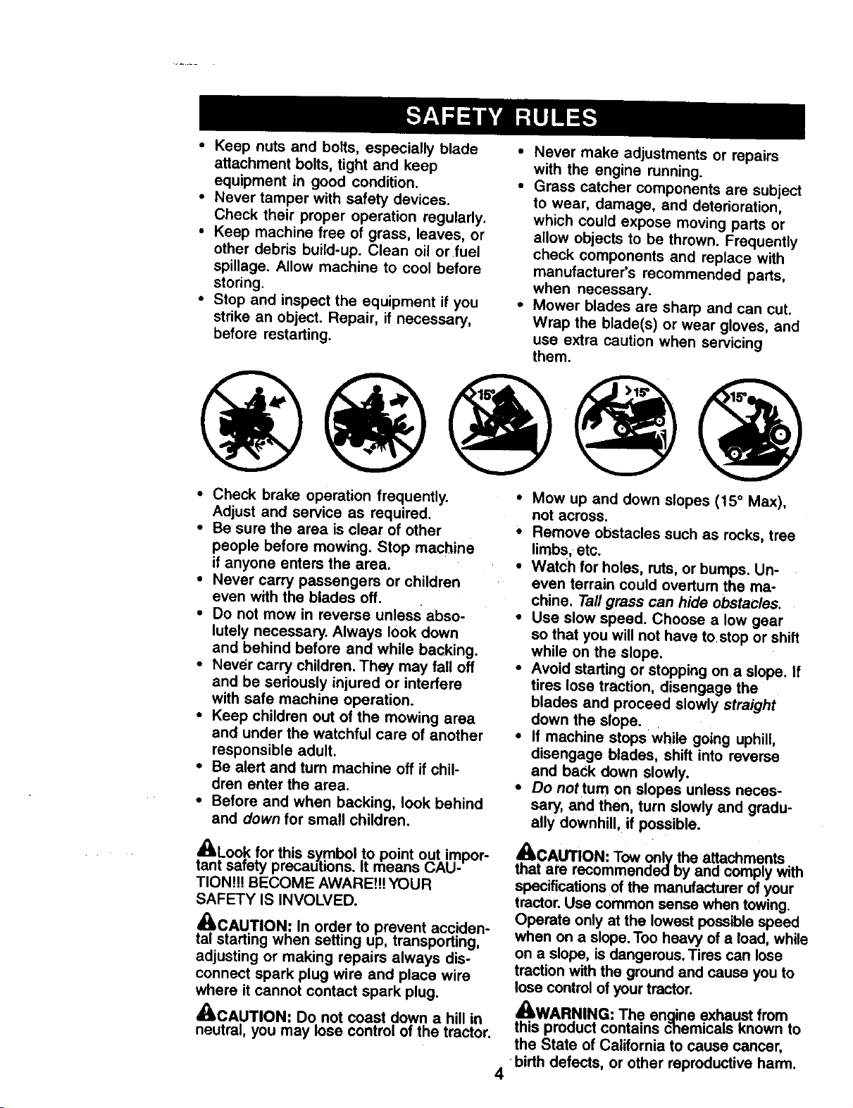
• Mow up and down slopes (15 ° Max),
not across.
• Remove obstacles such as rocks, tree
limbs, etc.
• Watch for holes, ruts, or bumps. Un-
even terrain could overturn the ma-
chine. Tall grass can hide obstacles.
• Use slow speed. Choose a low gear
so that you will not have to.stop or shift
while on the slope.
• Avoid starting or stopping on a slope. If
tires lose traction, disengage the
blades and proceed slowly straight
down the slope.
• If machine stops while going uphill,
disengage blades, shift into reverse
and back down slowly.
• Do nottum on slopes unless neces-
sary, and then, turn slowly and gradu-
ally downhill, if possible.
_kCAUTION: Tow only the attachments
that are recommendedby and comply with
specifications of the manufacturer of your
tractor. Use common sense when towing.
Operate only at the lowest possible speed
when on a slope. Too heavy of a load, while
on a slope, is dangerous. Tires can lose
traction with the ground and cause you to
lose control of your tractor.
_WARNING: The enaine exhaust from
this product contains c"hemicals known to
the State of California to cause cancer,
•birth defects, or other reproductive harm.
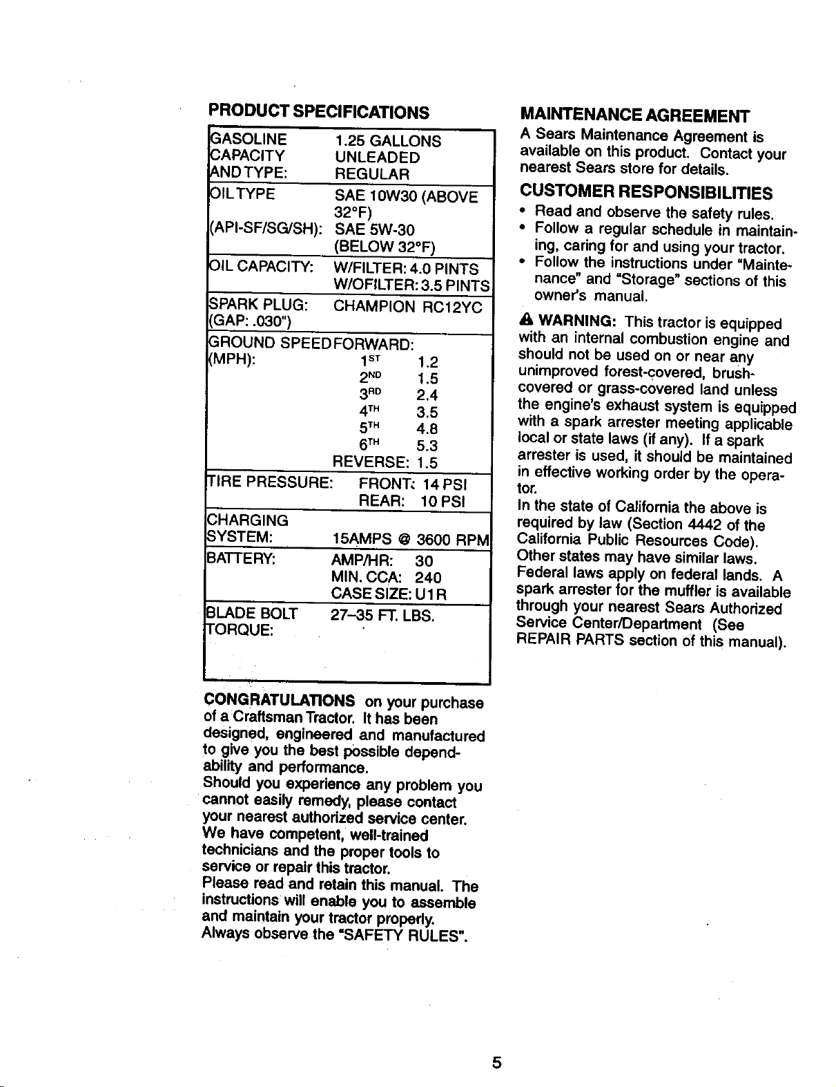
PRODUCT SPECIFICATIONS
3ASOLINE
_APACITY
A.NDTYPE:
OILTYPE
API-SF/SG/SH):
OIL CAPACITY:
SPARK PLUG:
GAP: .030")
1.25 GALLONS
UNLEADED
REGULAR
SAE 10W30 (ABOVE
32°F)
SAE 5W-30
(BELOW 32°F)
W/FILTER: 4.0 PINTS
W/OFILTER: 3.5 PINTS
CHAMPION RC12YC
5ROUND SPEEDFORWARD:
MPH): 1sT 1.2
2N° 1.5
3RO 2.4
4TM 3.5
5TM 4.8
6TM 5.3
REVERSE: 1.5
TIRE PRESSURE: FRONT_ 14 PSI
REAR: 10PSI
3HARGING
3YSTEM: 15AMPS @ 3600 RPM
IATTERY: AMP/HR: 30
MIN. CCA: 240
CASE SIZE: U1 R
3LADE BOLT 27--35 FT. LBS.
I'ORQUE:
MAINTENANCE AGREEMENT
A Sears Maintenance Agreement is
available on this product. Contact your
nearest Sears store for details.
CUSTOMER RESPONSIBILITIES
• Read and observe the safety rules.
• Follow a regular schedule in maintain-
ing, caring for and using your tractor.
• Follow the instructions under "Mainte-
nance" and "Storage" sections of this
owner's manual.
A, WARNING: This tractor is equipped
with an internal combustion engine and
should not be used on or near any
unimproved forest-covered, brush-
covered or grass-covered land unless
the engine's exhaust system is equipped
with a spark arrester meeting applicable
local or state laws (if any). If a spark
arrester is used, it should be maintained
in effective working order by the opera-
tor.
In the state of California the above is
required by law (Section 4442 of the
California Public Resources Code).
Other states may have similar laws.
Federal laws apply on federal lands. A
spark arrester for the muffler is available
through your nearest Sears Authodzed
Service Center/Department (See
REPAIR PARTS section of this manual).
V •
CONGRATULATIONS on your purchase
of a Craftsman Tractor. It has been
designed, engineered and manufactured
to give you the best possible depend-
ability and performance.
Should you experience any problem you
cannot easily remedy, please contact
your nearest authorized service center.
We have competent, well-trained
technicians and the proper tools to
service or repair this tractor.
Please read and retain this manual. The
instructions will enable you to assemble
and maintain your tractor properly.
Always observe the "SAFETY RULES".
5
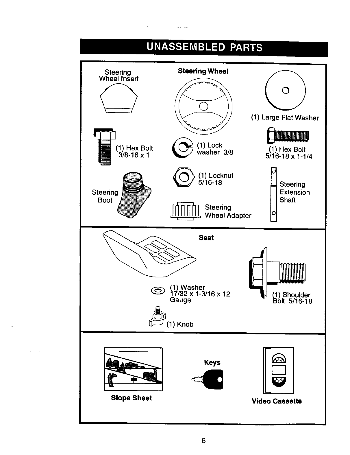
Steering
Wheel Insert
I_(1) Hex Bolt
3/8-16 x I
Steerin_
Boot
Steering Wheel
(1) Lock
washer 3/8
(1) Large Flat Washer
(1) Hex Bolt
5/16-18 x 1-1/4
(1) Locknut
5/16-18
=[_ Steering
Wheel Adapter
t teering
Extension
Shaft
Seat
(_Washer
(_) 17132 x 1-3/16 x 12
Gauge
I_(1) Knob
_) Shoulder
olt 5/16-18
Slope Sheet
Keys
Video Cassette
6
Your new tractor has been assembled at the factory with exception of those parts left
unassembled for shipping purposes. To ensure safe and proper operation of your
tractor all parts and hardware you assemble must be tightened securely. Use the
correct tools as necessary to insure proper tightness. Review the video cassette before
you begin.
TOOLS REQUIRED FOR
ASSEMBLY
A socket wrench set will make assembly
easier. Standard wrench sizes you need
are listed below.
(1) 9/16" wrench (1) Pliers
(2) 1/2"wrench (1) Utility knife
(1) 3/4" socket with
drive ratchet
(1) Tire pressure gauge
When rightor left hand Is mentioned in
this manual, it means, from your point of
view, when you are in the operating
position (seated behind the steering
wheel).
TO REMOVETRACTOR FROM
CARTON
UNPACK CARTON
• Remove all accessible loose parts
and parts boxes from shipping carton.
• Cut, from top to bottom, along lines on
all four comers of shipping carton, and
lay panels flat.
• Remove mower and packing materi-
als.
• Check for any additional loose parts or
boxes and remove.
BEFORE ROLLINGTRACTOR OFF
SKID
ATTACH STEERING WHEEL
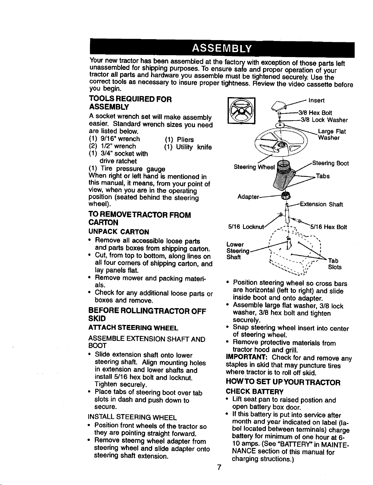
ASSEMBLE EXTENSION SHAFT AND
BOOT
• Slide extension shaft onto lower
steering shaft. Align mounting holes
in extension and lower shafts and
install 5/16 hex bolt and Iocknut.
Tighten securely.
• Place tabs of steering boot over tab
slots in dash and push down to
secure.
INSTALL STEERING WHEEL
• Position front wheels of the tractor so
they are pointing straight forward.
• Remove steerng wheel adapter from
steering wheel and slide adapter onto
steering shaft extension.
_ Insert
_.-.-----3/8 Hex Bolt
,_,..----.-3/8 Lock Washer
Large Flat
WasherBoot
Steering Wheel
.Tabs
7
Adapt_
.j_ension Shaft
5/16 Locknut/ ."'-'-_L-?, -5/16 Hex Bolt
Lower _ ',
ShaftSteeringF _..'/" '
tab
_.'- , ' " Slots
• Position steering wheel so cress bars
are horizontal (left to right) and slide
inside boot and onto adapter.
• Assemble large flat washer, 3/8 lock
washer, 3/8 hex bolt and tighten
securely.
• Snap steering wheel insert into center
of steering wheel.
• Remove protective materials from
tractor hood and grill.
IMPORTANT: Check for and remove any
staples in skid that may puncture tires
where tractor is to roll off skid.
HOW TO SET UP YOUR TRACTOR
CHECK BATTERY
• Lift seat pan to raised postion and
open battery box door.
• If this battery is put into service after
month and year indicated on label (la-
bel located between terminals) charge
battery for minimum of one hour at 6-
10 amps. (See =BATTERY" in MAINTE-
NANCE section of this manual for
charging structions.)
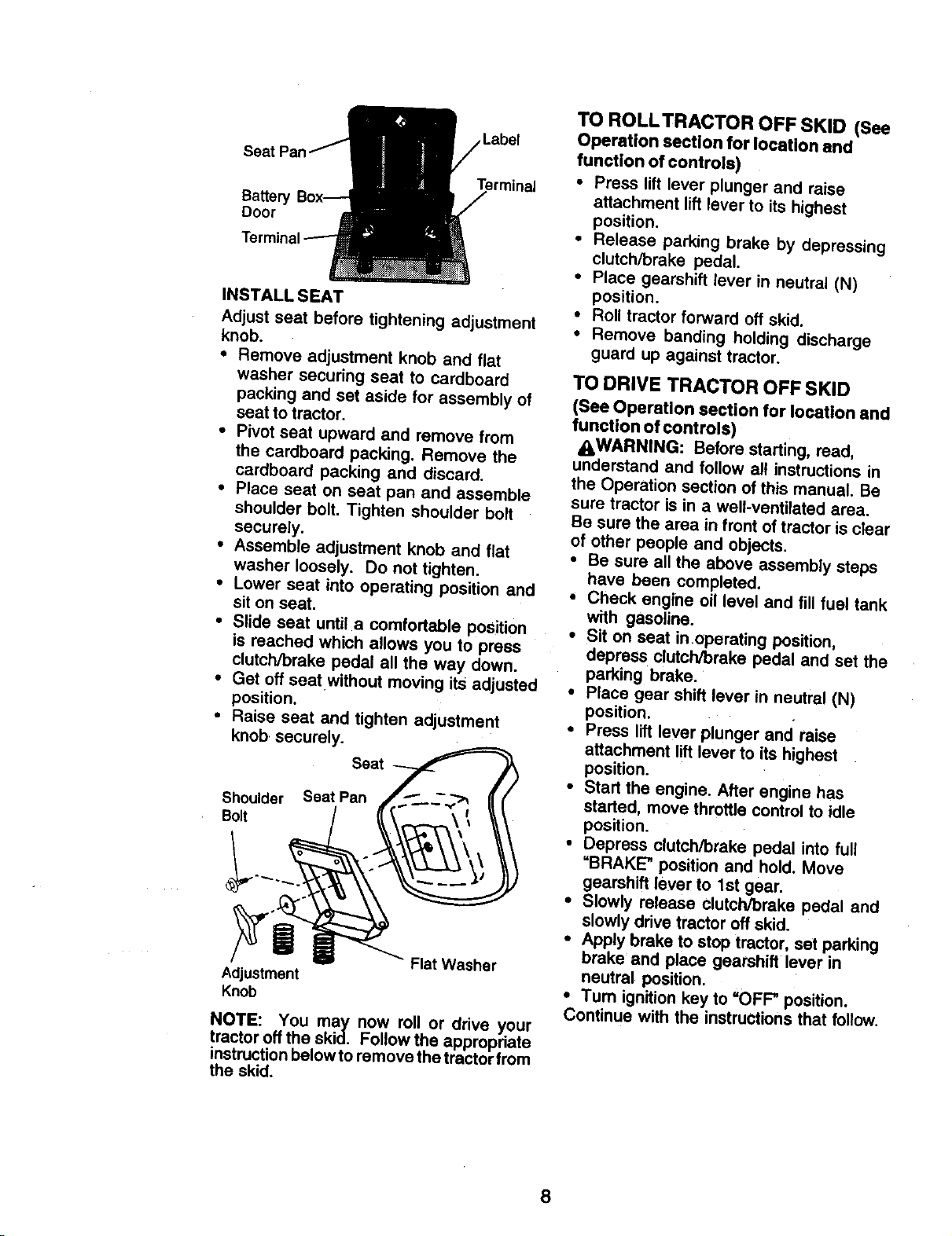
Labe{
Batter
Door
Terminal
INSTALL SEAT
Adjust seat before tightening adjustment
knob.
• Remove adjustment knob and flat
washer securing seat to cardboard
packing and set aside for assembly of
seat to tractor.
• Pivot seat upward and remove from
the cardboard packing. Remove the
cardboard packing and discard.
• Place seat on seat pan and assemble
shoulder bolt. Tighten shoulder bolt
securely.
• Assemble adjustment knob and flat
washer loosely. Do not tighten.
• Lower seat into operating position and
sit on seat.
• Slide seat until a comfortable position
is reached which allows you to press
clutch/brake pedal all the way down.
• Get off seat without moving its adjusted
position.
• Raise seat and tighten adjustment
knob securely.
Seat
Shoulder Seat Pan
Bolt
Flat Washer
Adjustment
Knob
NOTE: You may now roll or drive your
tractor off the skid. Follow the appropriate
instruction below to remove the tractor from
the skid.
TO ROLLTRACTOR OFF SKID (See
Operation section for location and
function of controls)
• Press lift lever plunger and raise
attachment lift lever to its highest
position.
• Release parking brake by depressing
clutch/brake pedal.
• Place gearshift lever in neutral (N)
position.
• Roll tractor forward off skid.
• Remove banding holding discharge
guard up against tractor.
TO DRIVE TRACTOR OFF SKID
(See Operation section for location and
function of controls)
AWARNING: Before starting, read,
understand and follow all instructions in
the Operation section of this manual. Be
sure tractor is in a well-ventilated area.
Be sure the area in front of tractor is clear
of other people and objects.
• Be sure all the above assembly steps
have been completed.
• Check engine oil level and fill fuel tank
with gasoline.
• Sit on seat in operating position,
depress clutch/brake pedal and set the
parking brake.
• Place gear shift lever in neutral (N)
position.
• Press lift lever plunger and raise
attachment lift lever to its highest
position.
• Start the engine. After engine has
started, move throttle control to idle
position.
• Depress clutch/brake pedal into full
UBRAKE" position and hold. Move
gearshift leve_ to 1st gear.
• Slowly release clutch/brake pedal and
slowly drive tractor off skid.
• Apply brake to stop tractor, set parking
brake and place gearshift lever in
neutral position.
• Turn ignition key to =OFF" position.
Continue with the instructions that follow.
8
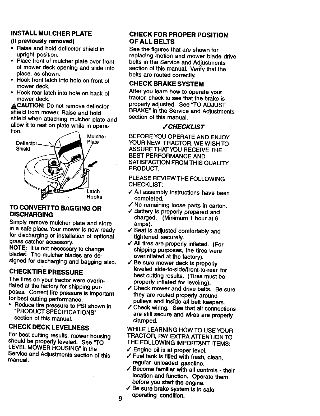
INSTALL MULCHER PLATE
(If previously removed)
• Raise and hold deflector shield in
upright position.
• Place front of mulcher plate over front
of mower deck opening and slide into
place, as shown.
• Hook front latch into hole on front of
mower deck.
• Hook rear latch into hole on back of
mower deck.
_CAUTION: Do not remove deflector
shield from mower. Raise and hold
shield when attaching mulcher plate and
allow it to rest on plate while in opera-
tion.
Mulcher
Plate
Shield
Latch
Hooks
TO CONVERTTO BAGGING OR
DISCHARGING
Simply remove mulcher plate and store
in a safe place. Your mower is now ready
for discharging or installation of optional
grass catcher accessory.
NOTE: It is not necessary to change
blades. The mulcher blades are de-
signed for discharging and bagging also.
CHECKTIRE PRESSURE
The tires on your tractor were overin-
flated at the factory for shipping pur-
poses. Correct tire pressure is important
for best cuttingperformance.
• Reduce tire pressure to PSI shown in
=PRODUCT SPECIFICATIONS"
section of this manual.
CHECK DECK LEVELNESS
For best cutting results, mower housing
should be properly leveled. See =TO
LEVEL MOWER HOUSING" in the
Service and Adjustments section of this
manual.
CHECK FOR PROPER POSITION
OF ALL BELTS
See the figures that are shown for
replacing motion and mower blade drive
belts in the Service and Adjustments
section of this manual. Verify that the
belts are routed correctly.
CHECK BRAKE SYSTEM
After you team how to operate your
tractor, check to see that the brake is
properly adjusted. See "TO ADJUST
BRAKE" in the Service and Adjustments
section of this manual.
,/CHECKLIST
BEFORE YOU OPERATE AND ENJOY
YOUR NEW TRACTOR, WE WISH TO
ASSURE THAT YOU RECEIVE THE
BEST PERFORMANCE AND
SATISFACTION FROM THIS QUALITY
PRODUCT.
9
PLEASE REVIEW THE FOLLOWING
CHECKLIST:
,/All assembly instructions have been
completed.
,/No remaining loose parts in carton.
,/Battery is properly prepared and
charged. (Minimum 1 hour at 6
amps).
,/Seat is adjusted comfortably and
tightened securely.
,/All tires are properly inflated. (For
shipping purposes, the tires were
overinflated at the factory).
,/Be sure mower deck is properly
leveled side-to-side/front-to-rear for
best cutting results. (Tires must be
properly inflated for leveling).
/ Check mower and drive belts. Be sure
they are routed properly around
pulleys and inside all belt keepers.
/ Check wiring. See that all connections
are still secure and wires are propedy
clamped.
WHILE LEARNING HOW TO USE YOUR
TRACTOR, PAY EXTRA ATTENTION TO
THE FOLLOWING IMPORTANT ITEMS:
,/Engine oil is at proper level.
,/Fuel tank is filled with fresh, clean,
regular unleaded gasoline.
,/Become familiar with all controls - their
location and function. Operate them
before you start the engine.
•/ Be sure brake system is in safe
operating condition.
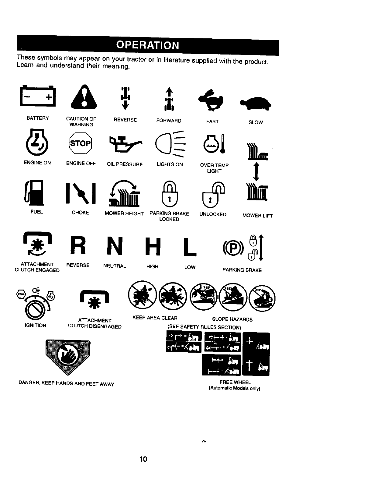
These symbols may appear on your tractor or in literature supplied with the product.
Learn and understand their meaning.
BA'I-FERY CAUTION OR REVERSE FORWARD FAST SLOW
WARNING
ENGINE ON ENGINE OFF OIL PRESSURE LIGHTS ON OVER TEMP
LIGHT
L
UNLOCKED MOWER LIFT
FUEL CHOKE MOWER HEIGHT
®
PARKING BRAKE
LOCKED
R N H L
ATTACHMENT REVERSE NEUTRAL HIGH LOW
CLUTCH ENGAGED PARKING BRAKE
ATTACHMENT KEEP AREA CLEAR
IGNITION CLUTCH DISENGAGED
SLOPE HAZARDS
(SEE SAFETY RULES SECTION)
DANGER, KEEP HANDS AND FEET AWAY
FREE WHEEL
(Automatic Models only)
,%
10
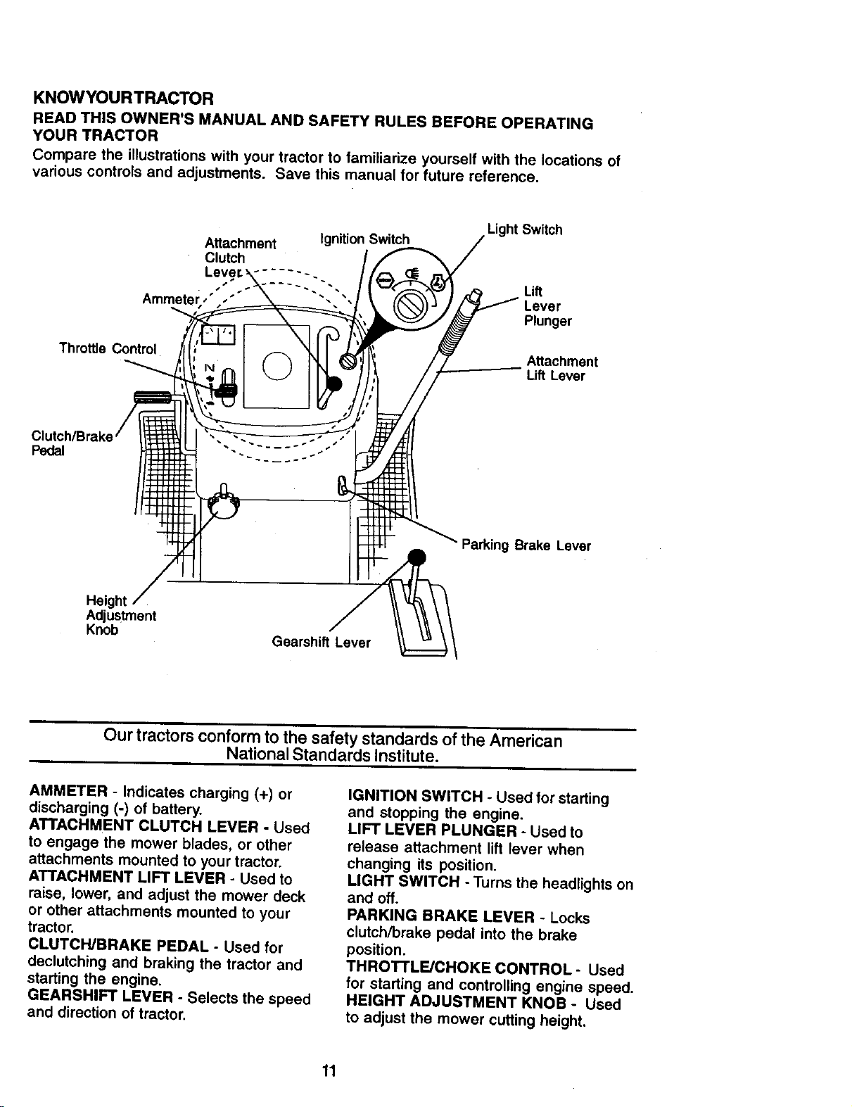
KNOWYOURTRACTOR
READ THIS OWNER'S MANUAL AND SAFETY RULES BEFORE OPERATING
YOUR TRACTOR
Compare the illustrations with your tractor to familiarize yourself with the locations of
various controls and adjustments. Save this manual for future reference.
Throttle Control
Attachment IgnitionSwitch
Clutch
:-2:::--
Light Switch
Lift
Lever
Plunger
Attachment
Lift Lever
Pedal
• Parking Brake Lever
Height
Adjustment
Knob
Gearshift Lever
Our tractors conform to the safety standards of the American
National Standards Institute.
AMMETER - Indicates charging (+) or
discharging (-) of battery.
ATTACHMENT CLUTCH LEVER - Used
to engage the mower blades, or other
attachments mounted to your tractor.
ATTACHMENT LIFT LEVER - Used to
raise, lower, and adjust the mower deck
or other attachments mounted to your
tractor.
CLUTCWBRAKE PEDAL - Used for
declutching and braking the tractor and
starting the engine.
GEARSHIFT LEVER - Selects the speed
and direction of tractor.
IGNITION SWITCH - Used for starting
and stopping the engine.
LIFT LEVER PLUNGER - Used to
release attachment lift lever when
changing its position.
LIGHT SWITCH - Turns the headlights on
and off.
PARKING BRAKE LEVER - Locks
clutch/brake pedal into the brake
position.
THROTTLE/CHOKE CONTROL- Used
for starting and controlling engine speed.
HEIGHT ADJUSTMENT KNOB - Used
to adjust the mower cutting height.
11
The operation of any tractor can result in foreign objects thrown into
the eyes, which can result in severe eye damage. Always wear safety
glasses or eye shields while operating your tractor or performing any
adjustments or repairs. We recommend a wide vision safety mask
over spectacles or standard safety glasses.
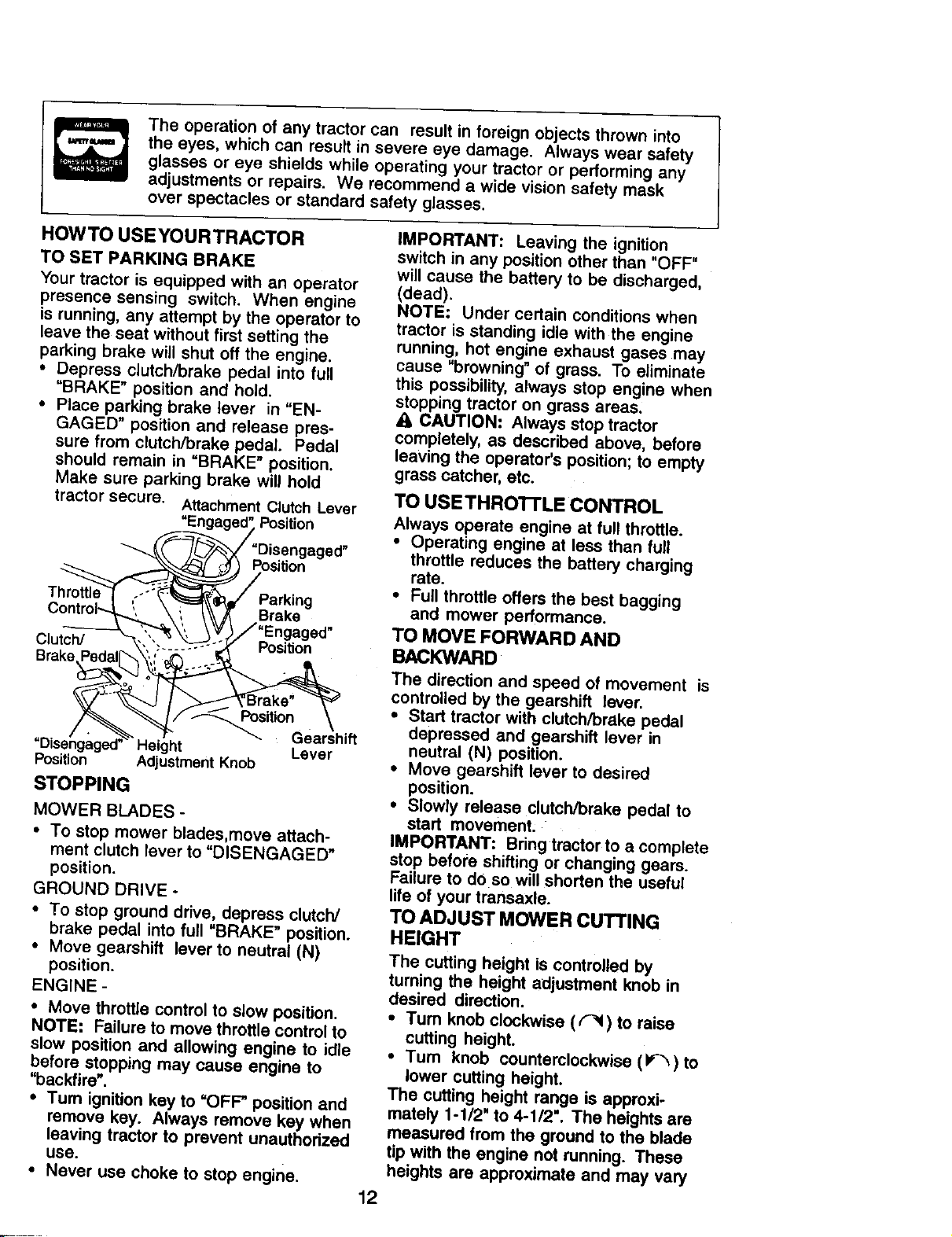
HOWTO USEYOURTRACTOR
TO SET PARKING BRAKE
Your tractor is equipped with an operator
presence sensing switch. When engine
is running, any attempt by the operator to
leave the seat without first setting the
parking brake will shut oft the engine.
• Depress clutch/brake pedal into full
"BRAKE" position and hold.
• Place parking brake lever in "EN-
GAGED" position and release pres-
sure from clutch/brake pedal. Pedal
should remain in "BRAKE" position,
Make sure parking brake will hold
tractor secure. Attachment Clutch Lever
"Engaged" Position
__"Disengaged"
-_ \\_.z_t%[ _ _ Position
Controb-..t,._' \ i _\-_ Brake
ClutcW--_-_ _ ",k___,'/; Engaged"
--_,, "..---- --":_'--"._ Position
Brake.Pedal_'___ _ =
/ • _ T- _- Gearshift
"Disengaged" Height Lever
Position Adjustment Knob
STOPPING
MOWER BLADES -
• To stop mower blades,move attach-
ment clutch lever to "DISENGAGED"
position.
GROUND DRIVE -
• To stop ground drive, depress clutch/
brake pedal into full "BRAKE" position.
• Move gearshift lever to neutral (N)
position.
ENGINE -
• Move throttle control to slow position.
NOTE: Failure to move throttle control to
slow position and allowing engine to idle
before stopping may cause engine to
"backfire".
• Turn ignition key to =OFF" position and
remove key. Always remove key when
leaving tractor to prevent unauthorized
use.
• Never use choke to stop engine.
IMPORTANT: Leaving the ignition
switch in any position other than "OFF"
will cause the battery to be discharged,
(dead).
NOTE: Under certain conditions when
tractor is standing idle with the engine
running, hot engine exhaust gases may
cause "browning" of grass. To eliminate
this possibility, always stop engine when
stopping tractor on grass areas.
CAUTION: Always stop tractor
completely, as described above, before
leaving the operator's position; to empty
grass catcher, etc.
TO USETHROI-rLE CONTROL
Always operate engine at full throttle.
• Operating engine at less than full
throttle reduces the battery charging
rate.
• Full throttle offers the best bagging
and mower performance.
TO MOVE FORWARD AND
BACKWARD
The direction and speed of movement is
controlled by the gearshift lever.
• Start tractor with clutch/brake pedal
depressed and gearshift lever in
neutral (N) position.
• Move gearshift lever to desired
position.
• Slowly release clutch/brake pedal to
start movement;
IMPORTANT: Bringtractor to a complete
stop before shifting or changing gears.
Failure to doso will shorten the useful
life of your transaxle.
TO ADJUST MOWER CUTTING
HEIGHT
The cutting height is controlled by
turning the height adjustment knob in
desired direction.
• Tum knob clockwise ((-_) to raise
cutting height.
•Tum knob counterclockwise (i*-'_)to
lower cutting height.
The cutting height range is approxi-
mately 1-1/2" to 4-112". The heights are
measured from the ground to the blade
tip with the engine not running. These
heights are approximate and may vary
12
depending upon soil conditions, height
of grass and types of grass being
mowed.
• The average lawn should be cut to
approximately 2-1/2 inches during the
cool season and to over 3 inches
during hot months. For healthier and
better looking lawns, mow often and
after moderate growth.
• For best cutting performance, grass
over 6 inches in height should be
mowed twice. Make the first cut
relatively high; the second to desired
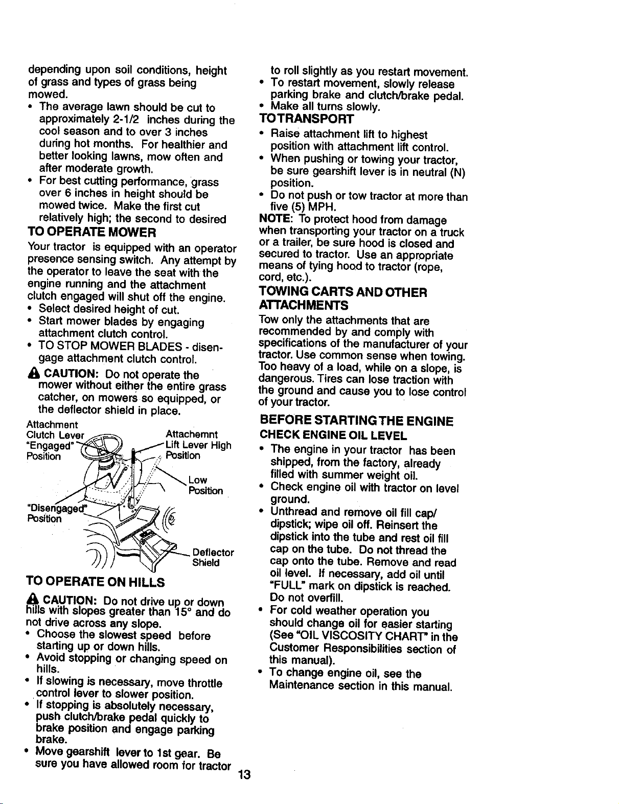
TO OPERATE MOWER
Your tractor is equipped with an operator
presence sensing switch. Any attempt by
the operator to leave the seat with the
engine running and the attachment
clutch engaged will shut oft the engine.
• Select desired height of cut.
• Start mower blades by engaging
attachment clutch control.
• TO STOP MOWER BLADES - disen-
gage attachment clutch control.
CAUTION: Do not operate the
mower without either the entire grass
catcher, on mowers so equipped, or
the deflector shield in place.
Attachment Attachemnt
Clutch Lever
=Enaaoed" _ , ).) _ /Lift Lever High
Pos_ion _ _ Position
"Disengagsd_. _"_" _--_/',_
TO OPERATE ON HILLS
h_iitCAUTION: Do not drive up or down
s with slopes greater than 15 ° and do
not drive across any slope.
• Choose the slowest speed before
starting up or down hills.
• Avoid stopping or changing speed on
hills.
• If slowing is necessary, move throttle
control lever to slower position.
• If stopping is absolutely necessary,
push clutch/brake pedal quickly to
brake position and engage parking
brake.
• Move gearshift leverto lstgear. Be
sure you have allowed room for tractor
to roll slightly as you restart movement.
• To restart movement, slowly release
parking brake and clutch/brake pedal.
• Make all turns slowly.
TOTRANSPORT
• Raise attachment lift to highest
position with attachment lift control.
• When pushing or towing your tractor,
be sure gearshift lever is in neutral (N)
position.
• Do not push or tow tractor at more than
five (5) MPH.
NOTE: To protect hood from damage
when transporting your tractor on a truck
or a trailer, be sure hood is closed and
secured to tractor. Use an appropriate
means of tying hood to tractor (rope,
cord, etc.).
TOWING CARTS AND OTHER
ATTACHMENTS
Tow only the attachments that are
recommended by and comply with
specifications of the manufacturer of your
tractor. Use common sense when towing.
Too heavy of a load. while on a slope, is
dangerous, Tires can lose traction with
the ground and cause you to lose control
of your tractor.
BEFORE STARTINGTHE ENGINE
CHECK ENGINE OIL LEVEL
• The engine in your tractor has been
shipped, from the factory, already
filled with summer weight oil.
• Check engine oil with tractor on level
ground.
• Unthread and remove oil fill cap/
dipstick;wipe oil off. Reinsert the
dipstick into the tube and rest oil fill
cap on the tube. Do not thread the
cap onto the tube. Remove and read
oil level. If necessary, add oil until
"FULL" mark on dipstick is reached.
Do not overfill.
• For cold weather operation you
should change oil for easier starting
(See =OIL VISCOSITY CHART" in the
Customer Responsibilities section of
this manual).
• To change engine oil, see the
Maintenance section in this manual.
13
ADDGASOLINE
• Fill fuel tank. Use fresh, clean, regular
unleaded gasoline with a minimum of
87 octane. (Use of leaded gasoline
will increase carbon and lead oxide
deposits and reduce valve life). Do
not mix oil with gasoline. Purchase
fuel in quantities that can be used
within 30 days to assure fuel fresh-
ness.
IMPORTANT: When operating in
temperatures below 32°F(0°C), use
fresh, clean winter grade gasoline to
help insure good cold weather starting.
a_c WARNING: Experience indicates that
ohol blended fuels (called gasohol or
using ethanol or methanol) can attract
moisture which leads to separation and
formation of acids during storage. Acidic
gas can damage the fuel system of an
engine while in storage. To avoid engine
problems, the fuel system should be
emptied before storage of 30 days or
longer. Drain the gas tank, start the
engine and let it run until the fuel lines
and carburetor are empty. Use fresh fuel
next season. See Storage Instructions
for additional information. Never use
engine or carburetor cleaner products in
the fuel tank or permanent damage may
Occur.
_I,eCAUTION: Fill to bottom of gas tank
r neck. Do not overfill. Wipe off any
spilled oil or fuel. Do not store, spill or
use gasoline near an open flame.
TO START ENGINE
When starting the engine for the first time
or if the engine has run out of fuel, it will
take extra cranking time to move fuel
from the tank to the engine.
• Sit on seat in operating position,
depress clutch/brake pedal and set
parking brake.
• Place gear shift lever in neutral (N)
position.
• Move attachment clutch to "DISEN-
GAGED" position.
• Move throttle control to choke position.
NOTE: Before starting, read the warm
and cold starting procedures below.
• Insert key into ignition and turn key
clockwise to "START" position and
release key as soon as engine starts.
Do not run starter continuously for
more than fifteen seconds per minute.
If the engine does not start after
several attempts, move throttle control
to fast position, wait a few minutes and
try again. If engine still does not start,
move the throttle control back to the
choke position and retry.
WARM WEATHER STARTING (50 ° F and
above)
• When engine starts, move the throttle
control to the fast position.
• The attachments and ground drive can
now be used. If the engine does not
accept the load, restart the engine and
allow it to warm up for one minute
using the choke as described above.
COLD WEATHER STARTING ( 50 ° F and
below)
• When engine starts, allow engine to
run with the throttle control in the
choke position until the engine runs
roughly, then move throttle control to
fast position. This may require an
engine warm-up pedod from several
seconds to several minutes, depend-
ing on the temperature.
• The attachments can also be used
during the engine warm-up period.
NOTE: If at a high altitude (above 3000
feet) or in cold temperatures (below 32
F) the carburetor fuel mixture may need
to be adjusted for best engine perfor-
mance. See "TO ADJUST CARBURE-
TOR" in the Service and Adjustments
section of this manual.
14
MOWINGTIPS
• Tire chains cannot be used when the
mower housing is attached to tractor.
• Mower should be propedy leveled for
best mowing performance. See =TO
LEVEL MOWER HOUSING" in the
Service and Adjustments section of
this manual.
• The left hand side of mower should be
used for trimming.
• Drive so that clippings are discharged
onto the area that has been cut. Have
the cut area to the right of the tractor.
This will result in a more even distribu-
tion of clippings and more uniform
cutting.
• When mowing large areas, start by
turning to the right so that clippings will
discharge away from shrubs, fences,
driveways, etc. After one or two
rounds, mow in the opposite direction
making left hand turns until finished.
• If grass is extremely tall, it should be
mowed twice to reduce load and
possible fire hazard from dried
clippings. Make first cut relatively
high; the second to the desired height.
• Do not mow grass when it is wet. Wet
grass will plug mower and leave
undesirable clumps. Allow grass to
dry before mowing.
• Always operate engine at full throttle
when mowing to assure better mowing
performance and proper discharge of
material. Regulate ground speed by
selecting a low enough gear to give
the mower cutting performance as well
as the quality of cut desired.
• When operating attachments, select a
ground speed that will suit the terrain
and give best performance of the
attachment being used.
f
t
m
MULCHING MOWlNGTIPS
IMPORTANT: For best performance,
keep mower housing free of built-up
grass and trash. Clean after each use.
• The special mulching blade will recut
the grass clippings many times and
reduce them in size so that as they fall
onto the lawn they will disperse into
the grass and not be noticed. Also, the
mulched grass will biodegrade quickly
to provide nutrients for the lawn.
Always mulch with your highest
engine (blade) speed as this will
provide the best recurringaction of the
blades.
• Avoid cutting your lawn when it is wet.
Wet grass tends to form clumps and
interferes with the mulching action.
The best time to mow your lawn is the
early afternoon. At this time the grass
has dried and the newly cut area will
not be exposed to the direct sun.
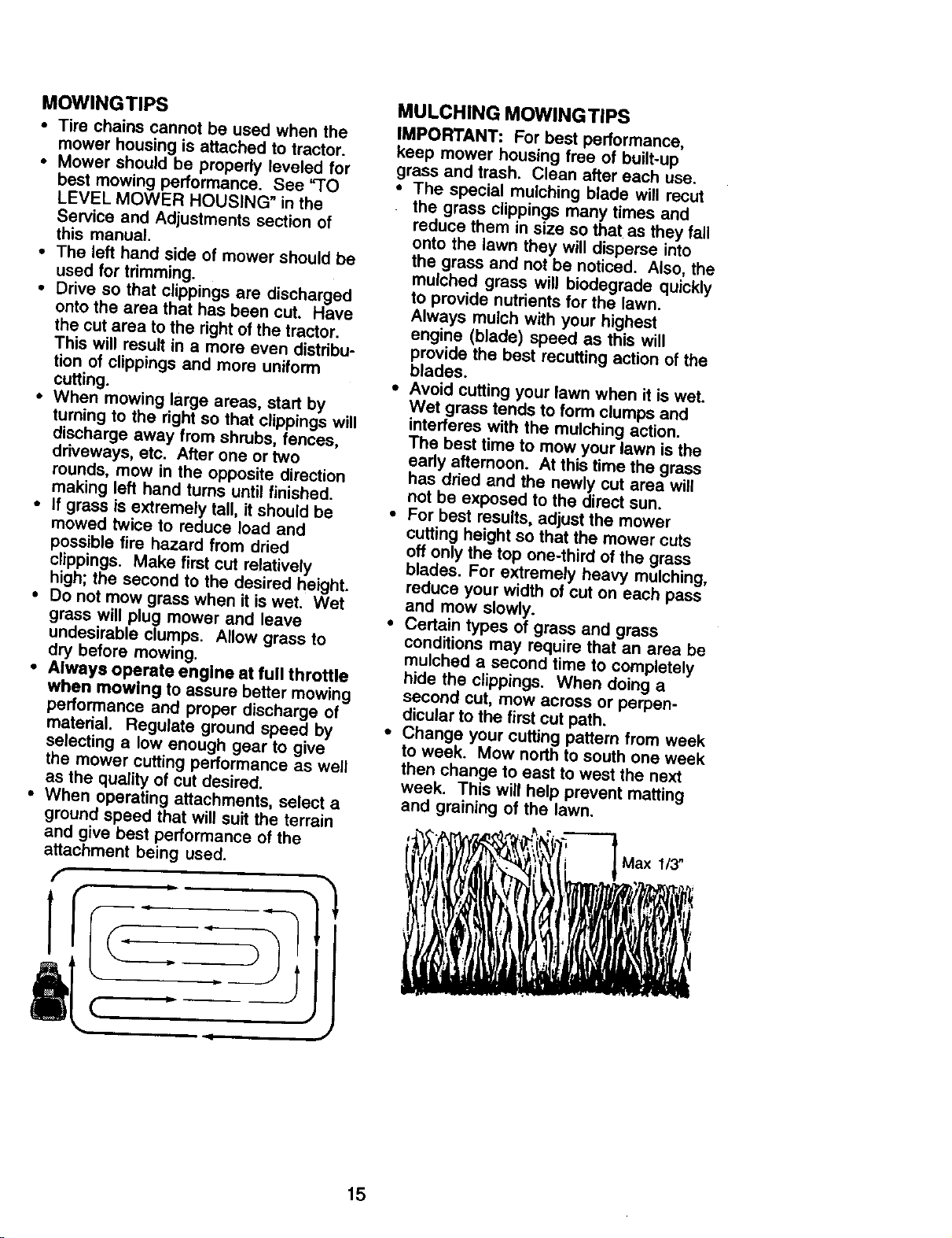
• For best results, adjust the mower
cutting height so that the mower cuts
off only the top one-third of the grass
blades. For extremely heavy mulching,
reduce your width of cut on each pass
and mow slowly.
• Certain types of grass and grass
conditions may require that an area be
mulched a second time to completely
hide the clippings. When doing a
second cut, mow across or perpen-
dicular to the first cut path.
• Change your cutting pattern from week
to week. Mow north to south one week
then change to east to west the next
week. This will help prevent matting
and graining of the lawn.
Max 1/3"
15
MAINTENANCE SCHEDULE .,_._"o_,_'n_/_
REGULAR SERVICE /__._._ _RVIC E DATES
Check Brake Operation
Check "13rePreSSure _
CheckOperatorPresenceand
T Interlock Systems I_
R Check_o_LeoseFastar_Ts M k#'7 t/
cA Sharpan/ReplaceMowerBlades i4
T Lub_o=_onChart I1_
0 Check Batte;y Levst
R Clean SatterJ and Term_a_s I_
Check Transaxle Costing _I_
Adiu_t B_ade Be!t(s) Tension l_s
Adjust Motion Drive Belt(s) Tension ii_s
Check Engine Oil Level _
ChangeEngineOil _#
E Clean Air Niter
N Clean Air Screen
G Inspect Muffler/Spark Arrestor I_ i
Replace Oil Rlter (If equipped) _,=
RE Clean Engine Cooling Rns
Replace Spark Plug _=
Replace Nr I_lter Paper Cartridge _z
Replace Fuel Rlter I I_
I -Chengemmeo#enwheneperatingu_leraheaWIoadm'inNsh_biem_w_. 5-ffequlpf_dwilh=d_u=_abl4syl_m_
2 - Secvice more often when op_ting in _ or _ ¢o_dll_=. 6 - N_ t_n_d If eq_ with maJntenan_4ree batter/.
3 - If _quip_ed wi_h_ (liter, chmRle oil ewry S0 hoUe=. ? - T_hten Iro_ md_ pi'mt bolt_o 3_ It,-I_, maximum.
4 - Replac_ bladn m_e olttn when _ in u_y =rail. Do not ov_dghlen.
GENERAL RECOMMENDATIONS
The warranty on this tractor does not
cover items that have been subjected to
operator abuse or negligence. To
receive full value from the warranty,
operator must maintain tractor as
instructed in this manual.
Some adjustments will need to be made
periodically to properly maintain your
tractor.
All adjustments in the Service and
Adjustments section of this manual
should be checked at least once each
season.
• Once a year you should replace the
spark plug, clean or replace air filter,
and check blades and belts for wear.
A new spark plug and clean air filter
assure proper air-fuel mixture and
help your engine run better and last
longer.
BEFORE EACH USE
• Check engine oil level.
• Check brake operation.
• Check tire pressure.
• Check operator presence and
intedock systems for proper operation.
• Check for loose fasteners.
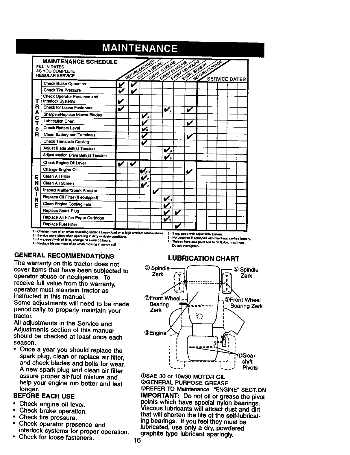
LUBRICATION CHART
_) Spindle-- - (_ spindle
Zerk _;_' Zsrk
_Front Wheel
Bearing Bearing Zerk
Zerk
@Engine'
"- r 'r- • shift
__ .... Pivots
(_SAE 30 or 10w30 MOTOR OIL
(_)GENERAL PURPOSE GREASE
_)REFER TO Maintenance "ENGINE" SECTION
IMPORTANT: Do not oil or grease the pivot
points which have special nylon beatings.
Viscous lubricants will attract dust and dirt
that will shorten the life of the self-lubricat-
ing bearings. If you feel they must be
lubricated, use only a dry, powdered
graphite type lubricant sparingly.
16
TRACTOR
Always observe safety rules when
performing any maintenance.
BRAKE OPERATION
If tractor requires more than six (6) feet
stopping distance at high speed in
highest gear, then brake must be
adjusted. (See "TO ADJUST BRAKE" in
the Service and Adjustments section of
this manual).
TIRES
• Maintain proper air pressure in all tires
(See "PRODUCT SPECIFICATIONS"
section of this manual).
• Keep tires free of gasoline, oil, or
insect control chemicals which can
harm rubber.
• Avoid stumps, stones, deep ruts, sharp
objects and other hazards that may
cause tire damage,
NOTE: To seal tire punctures and
prevent flat tires due to slow leaks, tire
sealant may be purchased from your
local parts dealer. Tire sealant also
prevents tire dry rot and corrosion.
OPERATOR PRESENCE SYSTEM
Be sure operator presence and interlock
systems are working properly, If your
tractor does not function as described,
repair the problem immediately.
• The engine should not start unless the
clutch/brake pedal is fully depressed
and attachement clutch control is in
the disengaged position.
• When the engine is running, any
attempt by the operator to leave the
seat without first setting the parking
brake should shut off the engine.
• When the engine is running and the
attachment clutch is engaged, any
attempt by the operator to leave the
seat should shut off the engine.
• The attachment clutch should never
operate unless the operator is in the
seat.
BLADE CARE
For best results mower blades must be
kept sharp. Replace bent or damaged
blades.
BLADE REMOVAL
• Raise mower to highest position to
allow access to blades.
• Remove hex bolt, lock washer and flat
washer secudng blade.
• Install new or rasharpened blade with
trailing edge up towards deck as
shown.
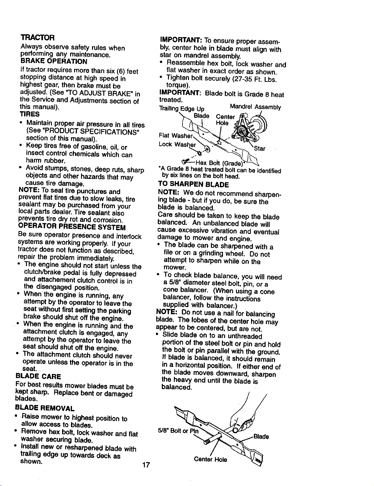
IMPORTANT: To ensure proper assem-
bly, center hole in blade must align with
star on mandrel assembly.
• Reassemble hex bolt, lock washer and
flat washer in exact order as shown.
• Tighten bolt securely (27-35 Ft. Lbs.
torque);
IMPORTANT: Blade bolt is Grade 8 heat
treated.
Mandrel Assembly
Trailing Edge Up /
Blade Center
::kWwaS::__ 'Star
_----Hex Bolt (Grade) _:_
*A Grade 8 heat treated bolt can be identified
by six lines on the bolthead.
TO SHARPEN BLADE
NOTE: We do not recommend sharpen-
ing blade - but if you do, be sure the
blade is balanced.
Care should be taken to keep the blade
balanced. An unbalanced blade will
cause excessive vibration and eventual
damage to mower and engine.
• The blade can be sharpened with a
file or on a grinding wheel. Do not
attempt to sharpen while on the
mower.
• To check blade balance, you will need
a 5/8" diameter steel bolt, pin, or a
cone balancer. (When using a cone
balancer, follow the instructions
supplied with balancer,)
NOTE: Do not use a nail for balancing
blade. The lobes of the center hole may
appear to be centered, but are not.
, Slide blade on to an unthraaded
portion of the steel bolt or pin and hold
the bolt or pin parallel with the ground.
If blade is balanced, it should remain
in a horizontal position. If either end of
the blade moves downward, sharpen
the heavy end until the blade is
balanced.
5/8" " e
Center Hole -v_
17
BA'n'ERY
Your tractor has a battery charging
system which is sufficient for normal use.
However, periodic charging of the battery
with an automotive charger will extend
its life.
• Keep battery and terminals clean,
• Keep battery bolts tight.
• Keep small vent holes open.
• Recharge at 6-10 amperes for 1 hour.
NOTE: The original equipment battery on
your tractor is maintenance free. Do not
attempt to open or remove caps or
covers. Adding or checking level of
electrolyte is not necessary.
TO CLEAN BATTERY AND TERMINALS
Corrosion and dirt on the battery and
terminals can cause the battery to "leak"
power.
• Open battery box door.
• Disconnect BLACK battery cable first
then RED battery cable and remove
battery from tractor.
• Rinse the battery with plain water and
dry.
• Clean terminals and battery cable
ends with wire brush until bright.
• Coat terminals with grease or petro-
leum jelly.
• Reinstall battery (See "REPLACING
BATTERY" in the SERVICE AND
ADJUSTMENTS section of this
manual).
V-BELTS
Check V-belts for deterioration and wear
after 100 hours of operation and replace
if necessary. The belts are not adjustable.
Replace belts if they begin to slip from
wear.
TRANSAXLE COOLING
Keep transaxle free from build-up of dirt
and chaff which can restrict cooling.
ENGINE
LUBRICATION
Only use high quality detergent oil rated
with API service classification SF, SG, or
SH. Select the oil's SAE viscosity grade
according to your expected operating
temperature.
Change the oil after every 50 hours of
operation or at least once a year if the
tractor is not used for 50 hours in one
year.
Check the crankcase oil level before
starting the engine and after each eight
(8) hours of operation. Tighten oil fill cap/
dipstick securely each time you check the
oil level.
TO CHANGE ENGINE OIL
Determine temperature range expected
before oil change. All oil must meet API
service classification SF, SG or SH.
• Be sure tractor is on level surface,
• Oil will drain more freely when warm.
• Catch oil in a suitable container.
• Remove oil fill cap/dipstick. Be careful
not to allow dirt to enter the engine
when changing oil.
• Remove drain plug.
• After oil has drained completely,
replace oil drain plug and tighten
securely.
• Refill engine with oil through oil fill
dipstick tube. Pour slowly. Do not
overfill. For approximate capacity see
=PRODUCT SPECIFICATIONS"
section of this manual.
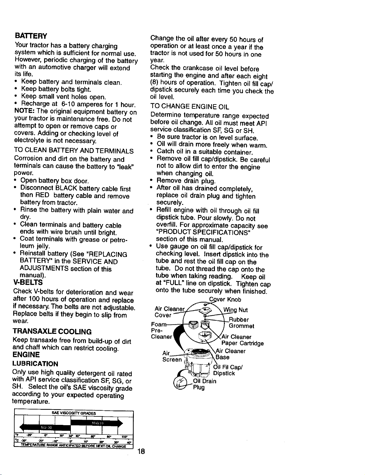
• Use gauge on oil fill cap/dipstick for
checking level. Insert dipstick into the
tube and rest the oil fill cap on the
tube. Do not thread the cap onto the
tube when taking reading. Keep oil
at "FULL" line on dipstick. Tighten cap
onto the tube securely when finished.
.,F_ve r Knob
Air Cleanej.,l_.-_ _W_g Nut
Cover -- ( -- _ _'_..Rubber
Foa_ _ } Grommet
P;eeaner_ - _.. _"_Air Cleaner
_ Paper Cartddge
Air \_ .._Air Cleaner
- Base
_ = Oi_Fil Cap/
_ Dipstick
O rain
Plug
18
CLEAN AIR SCREEN
Air screen must be kept free of dirt and
chaff to prevent engine damage from
overheating. Clean with a wire brush or
compressed air to remove dirt and
stubborn dried gum fibers.
CLEAN AIR INTAKE/COOLING
AREAS
To insure proper cooling, make sure the
grass screen, cooling fins, and other
external surfaces of the engine are kept
clean at all times.
Every 100 hours of operation (more often
under extremely dusty, dirty conditions),
remove the blower housing and other
cooling shrouds. Clean the cooling fins
and external surfaces as necessary.
Make sure the cooling shrouds are
reinstalled.
NOTE: Operating the engine with a
blocked grass screen, dirty or plugged
cooling fins, and/or cooling shrouds
removed will cause engine damage due
to overheating.
AIR FILTER
Your engine will not run properly using a
dirty airfilter. Clean the foam pre-
cleaner after every 25 hours of operation
or every season. Service paper car-
tridge every 100 hours of operation or
every season, whichever occurs first.
Service air cleaner more often under
dusty conditions.
• Remove knob and cover.
• Remove wing nut and air cleaner from
base.
TO SERVICE PRE-CLEANER
• Slide foam pre-cleaner off cartridge.
• Wash it in liquid detergent and water.
• Squeeze it dry in a clean cloth. Allow
it to dry.
• Saturate it in engine oil. Wrap it in
clean, absorbent cloth and squeeze to
remove excess oil.
TO SERVICE CARTRIDGE
• Replace a dirty, bent, or damaged
cartridge.
NOTE: Do not wash the paper cartridge
or use pressurized air, as this will
damage the cartridge.
• Reinstall the pre-cleaner (cleaned
and oiled) over the paper cartridge.
• Reassemble air cleaner, wing nut,
cover and tighten knob securely.
MUFFLER
Inspect and replace corroded muffler
and spark arrester (if equipped) as it
could create a fire hazard and/or
damage.
SPARKPLUGS
Replace spark plugs at the beginning of
each mowing season or after every 100
hours of operation, whichever occurs
first. Spark plug type and gap setting are
shown in "PRODUCT SPECIFICATIONS"
section of this manual.
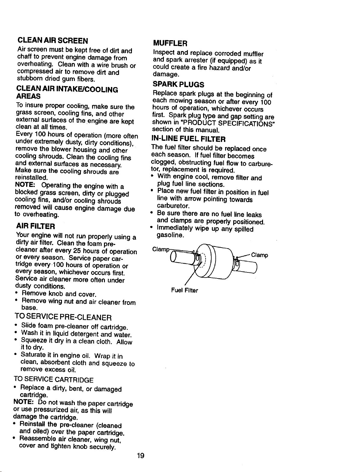
IN-LINE FUEL FILTER
The fuel filter should be replaced once
each season. If fuel filter becomes
clogged, obstructing fuel flow to carbure-
tor, replacement is required.
• With engine cool, remove filter and
plug fuel line sections.
• Place new fuel filter in position in fuel
line with arrow pointing towards
carburetor.
• Be sure there are no fuel line leaks
and clamps are propedy positioned.
• Immediately wipe up any spilled
gasoline.
Clam_amp
Fuel Filter
19
CLEANING
Clean engine, battery, seat, finish, etc.
of all fore=gn matter.
Keep finished surfaces and wheels
free of all gasoline, oil, etc.
• Protect painted surfaces with automo-
tive type wax.
We do not recommend using a garden
hose to clean your tractor unless the
electrical system, muffler, air filter and
carburetor are covered to keep water out.
Water in engine can result in a short-
ened engine life.
_I_CAUTION: Before performing any service or adjustments:
Depress clutch/brake pedal fully and set parking brake.
• Plaice gearshift lever in neutral (N)position.
• Place attachment clutch in DISENGAGED position.
Turn ignition key =OFF'* and remove key.
Make sure the blades and all moving pads have completely stopped.
• Disconnect spark plug wire from spark plug and place wire where it cannot
come in contact with plug.
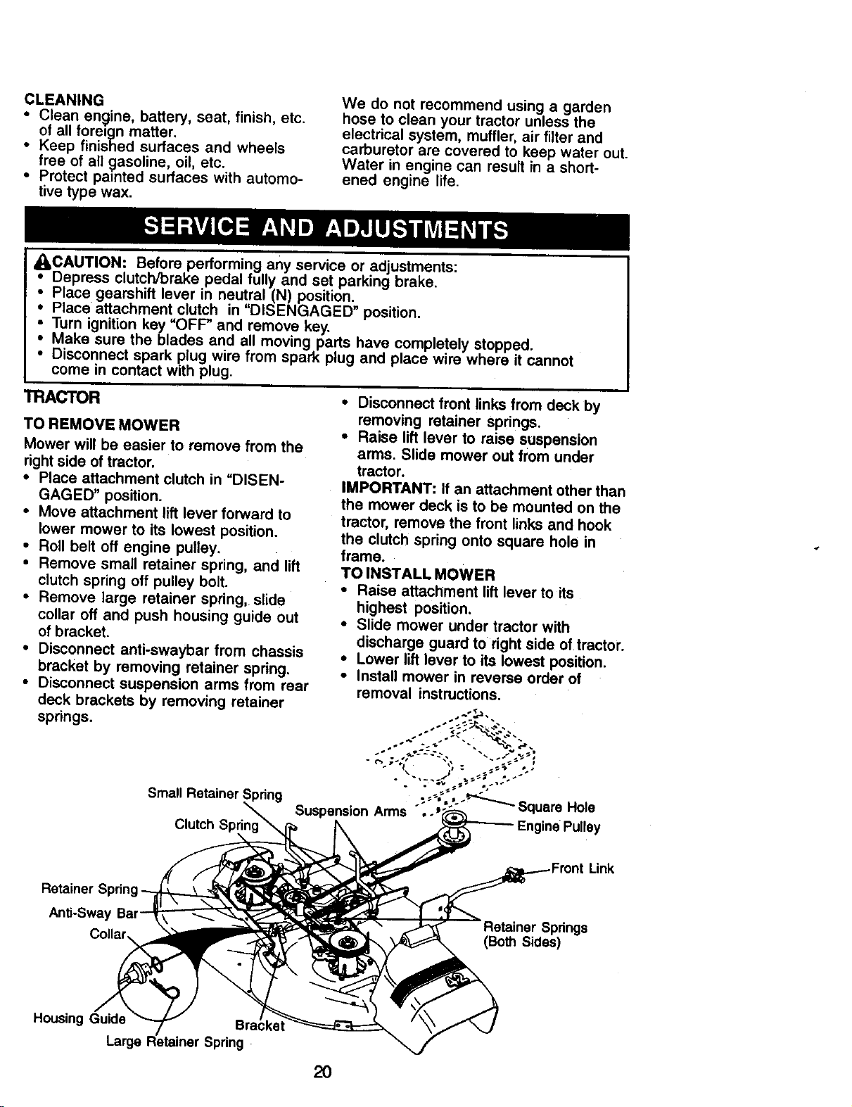
TRACTOR • Disconnect front links from deck by
TO REMOVE MOWER
Mower will be easier to remove from the
right side of tractor,
• Place attachment clutch in =DISEN-
GAGED" position.
• Move attachment lift lever forward to
lower mower to its lowest position.
• Roll belt off engine pulley.
• Remove small retainer spring, and lift
clutch spring off pulley bolt.
• Remove large retainer spring, slide
collar off and push housing guide out
of bracket.
• Disconnect anti-swaybar from chassis
bracket by removing retainer spring,
• Disconnect suspension arms from rear
deck brackets by removing retainer
springs.
Small Retainer Spdng
removing retainer springs.
• Raise lift lever to raise suspension
arms. Slide mower out from under
tractor.
IMPORTANT: If an attachment other than
the mower deck is to be mounted on the
tractor, remove the front links and hook
the clutch spring onto square hole in
frame.
TO INSTALL MOWER
• Raise attachment liftlever to its
highest position.
• Slide mower under tractor with
discharge guard to rightside of tractor.
• Lower liftlever to its lowest position.
• Install mower in reverse order of
removal instructions.
Clutch
Retainer S
Anti-Sway
:Link
Springs
(Both Sides)
Housing Guide
Large
2O
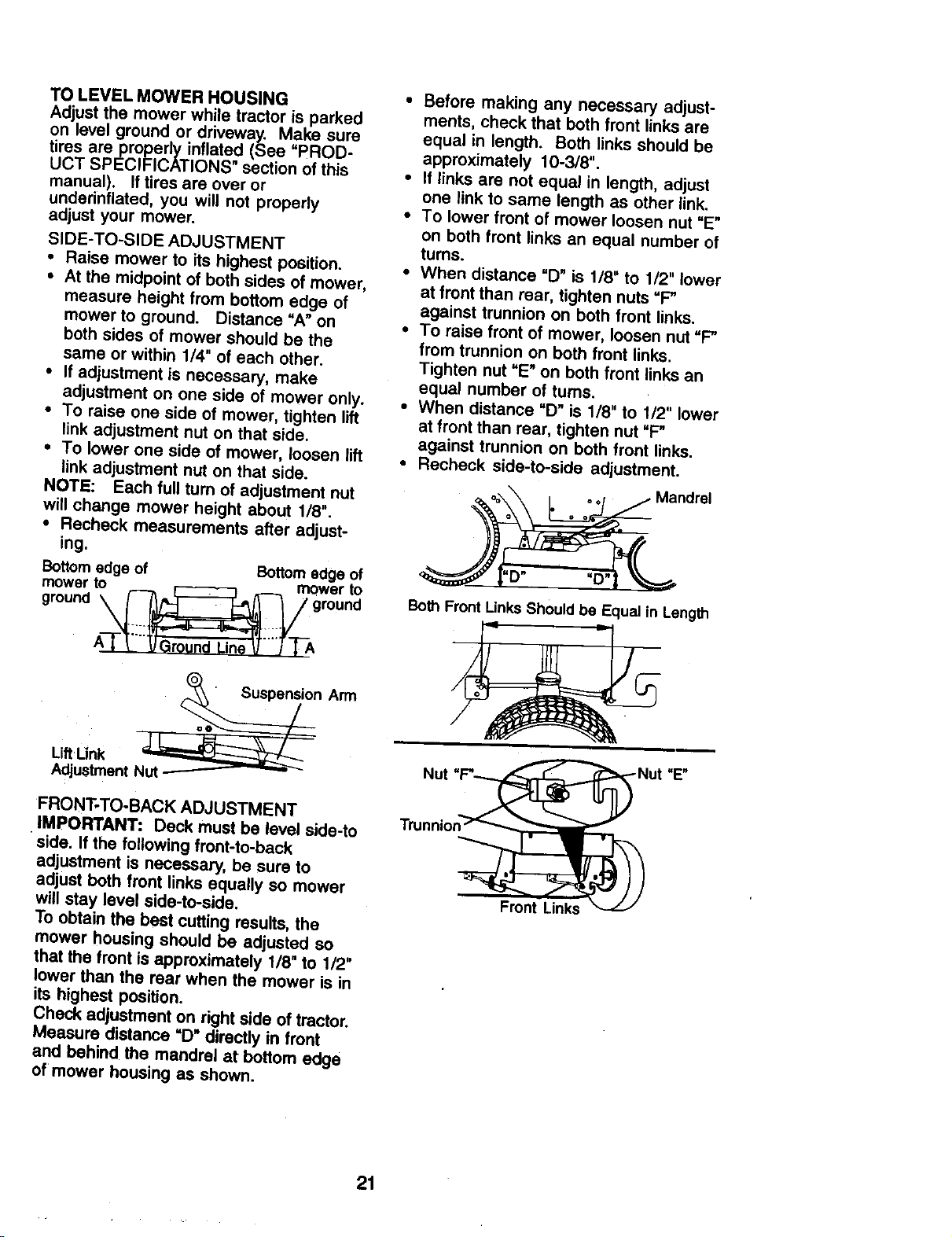
TO LEVEL MOWER HOUSING
Adjust the mower while tractor is parked
on level ground or driveway. Make sure
tres areproperly inflated (See "PROD-
UCT SPECIFICATIONS section of ths
manual). If tires are over or
underinflated, you will not properly
adjust your mower.
SIDE-TO-SIDE ADJUSTMENT
• Raise mower to its highest position.
• At the midpoint of both sides of mower,
measure height from bottom edge of
mower to ground. Distance =A" on
both sides of mower should be the
same or within 1/4 _ of each other.
• If adjustment is necessary, make
adjustment on one side of mower only.
• To raise one side of mower, tighten lift
link adjustment nut on that side.
• To lower one side of mower, loosen lift
link adjustment nut on that side.
NOTE: Each full turn of adjustment nut
will change mower height about 1/8".
• Recheck measurements after adjust-
ing.
Bottom edge of Bottom edge of
mower to _ mower to
ground _ ground
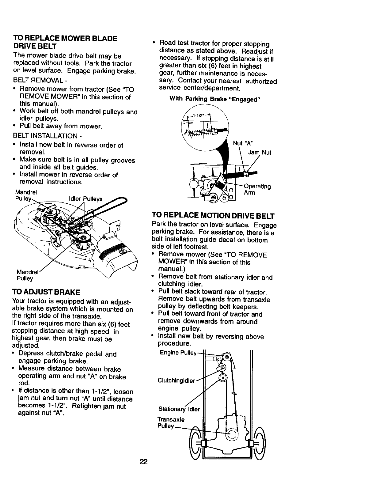
Before making any necessary adjust-
ments, check that both front links are
equal in length. Both links should be
approximately 10-3/8".
If links are not equal in length, adjust
one link to same length as other link.
To lower front of mower loosen nut "E"
on both front links an equal number of
turns.
When distance =D" is 1/8" to 1/2" lower
at front than rear, tighten nuts "F"
against trunnion on both front links.
To raise front of mower, loosen nut "F"
from trunnion on both front links.
Tighten nut =E" on both front links an
equal number of turns.
When distance =D" is 1/8" to 1/2" lower
at front than rear, tighten nut "F-"
against trunnion on both front links.
Recheck side-to-side adjustment.
Mandrel
=D"
Both Front Links Should be Equal in Length
Suspension Arm
Lift Unk
Adjustment
FRONT-TO-BACK ADJUSTMENT
IMPORTANT: Deck must be level side-to
side. If the following front-to-beck
adjustment is necessary, be sure to
adjust both front links equally so mower
will stay level side-to-side.
To obtain the best cutting results, the
mower housing should be adjusted so
that the front is approximately 118" to 1/2"
lower than the rear when the mower is in
its highest position.
Check adjustment on right side of tractor.
Measure distance "D" directly in front
and behind the mandrel at bottom edge
of mower housing as shown.
Front Links
=E"
21
TO REPLACE MOWER BLADE
DRIVE BELT
The mower blade drive belt may be
replaced without tools. Park the tractor
on level surface. Engage parking brake.
BELT REMOVAL -
• Remove mower from tractor (See "TO
REMOVE MOWER" in this section of
this manual).
• Work belt off both mandrel pulleys and
idler pulleys.
• Pull belt away from mower.
BELT INSTALLATION -
• Install new belt in reverse order of
removal.
• Make sure belt is in all pulley grooves
and inside all belt guides.
• Install mower in reverse order of
removal instructions.
Mandrel
Idler
• Road test tractor for proper stopping
distance as stated above. Readjust if
necessary. If stopping distance is still
greater than six (6) feet in highest
gear, further maintenance is neces-
sary. Contact your nearest authorized
service center/department.
With Parking Brake "Engaged"
Nut "A"
Nut
Arm
Pulley
TO ADJUST BRAKE
Your tractor is equipped with an adjust-
able brake system which is mounted on
the right side of the transaxte.
If tractor requires more than six (6) feet
stopping distance at high speed in
highest gear, then brake must be
adjusted.
• Depress clutch/brake pedal and
engage parking brake.
• Measure distance between brake
operating arm and nut "A" on brake
rod.
• If distance is other than 1-1/2", loosen
jam nut and turn nut "A" until distance
becomes 1-1/2". Retighten jam nut
against nut "A".
22
TO REPLACE MOTION DRIVE BELT
Park the tractor on level surface. Engage
parking brake. For assistance, there is a
belt installation guide decal on bottom
side of left footrest.
• Remove mower (See "TO REMOVE
MOWER" in this section of this
manual.)
Remove belt from stationary idler and
clutching idler.
Pull belt slack toward rear of tractor,
Remove belt upwards from transaxle
pulley by deflecting belt keepers.
Pull belt toward front of tractor and
remove downwards from around
engine pulley.
Install new belt by reversing above
procedure.
Engine Pulley-- ,,
Clutchingldler j
u"? 0
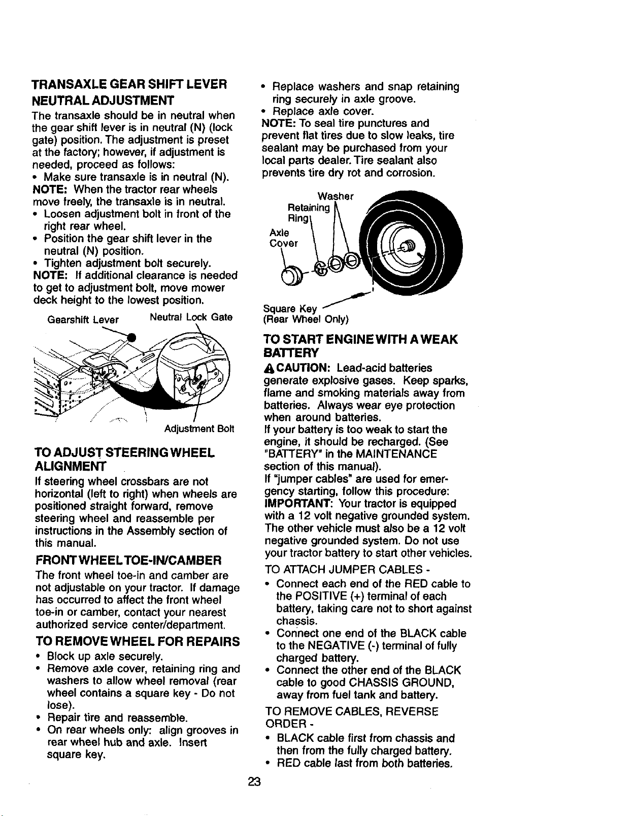
TRANSAXLE GEAR SHIFTLEVER
NEUTRAL ADJUSTMENT
The transaxle should be in neutral when
the gear shift lever is in neutral (N) (lock
gate) position. The adjustment is preset
at the factory; however, if adjustment is
needed, proceed as follows:
• Make sure transaxle is in neutral (N).
NOTE: When the tractor rear wheels
move freely, the transaxle is in neutral.
• Loosen adjustment bolt in front of the
right rear wheel.
• Position the gear shift lever in the
neutral (N) position.
• Tighten adjustment bolt securely.
NOTE: If additional clearance is needed
to get to adjustment bolt, move mower
deck height to the lowest position.
Gearshift Lever Neutral Lock Gate
Adjustment Bolt
TO ADJUST STEERING WHEEL
ALIGNMENT
If steering wheel crossbars are not
horizontal (left to right) when wheels are
positioned straight forward, remove
steering wheel and reassemble per
instructionsin the Assembly section of
this manual.
FRONT WHEELTOE-IN/CAMBER
The front wheel toe-in and camber are
not adjustable on your tractor. If damage
has occurred to affect the front wheel
toe-in or camber, contact your nearest
authorized service center/department.
TO REMOVE WHEEL FOR REPAIRS
• Block up axle securely.
• Remove axle cover, retaining ring and
washers to allow wheel removal (rear
wheel contains a square key - Do not
lose).
• Repair tire and reassemble.
• On rear wheels only: align grooves in
rear wheel hub and axle. Insert
square key.
• Replace washers and snap retaining
ring securely in axle groove.
• Replace axle cover.
NOTE: To seal tire punctures and
prevent flat tires due to slow leaks, tire
sealant may be purchased from your
local parts dealer. Tire sealant also
prevents tire dry rot and corrosion.
Washer
Retaining
Axle
Cover
I
Square Key "J
(Rear Wheel Only)
TO START ENGINE WITH AWEAK
BATTERY
A CAUTION: Lead-acid batteries
generate explosive gases. Keep sparks,
flame and smoking materials away from
batteries. Always wear eye protection
when around batteries.
If your battery is too weak to start the
engine, it should be recharged. (See
"BATTERY" in the MAINTENANCE
section of this manual).
If "jumper cables" are used for emer-
gency starting, follow this procedure:
IMPORTANT: Your tractor is equipped
with a 12 volt negative grounded system.
The other vehicle must aJso be a 12 volt
negative grounded system. Do not use
your tractor battery to start other vehicles.
TO ATTACH JUMPER CABLES -
• Connect each end of the RED cable to
the POSITIVE (+) terminal of each
battery, taking care not to short against
chassis.
• Connect one end of the BLACK cable
to the NEGATIVE (-) terminal of fully
charged battery.
• Connect the other end of the BLACK
cable to good CHASSIS GROUND,
away from fuel tank and battery.
TO REMOVE CABLES, REVERSE
ORDER -
• BLACK cable first from chassis and
then from the fully charged battery.
• RED cable last from both batteries.
23
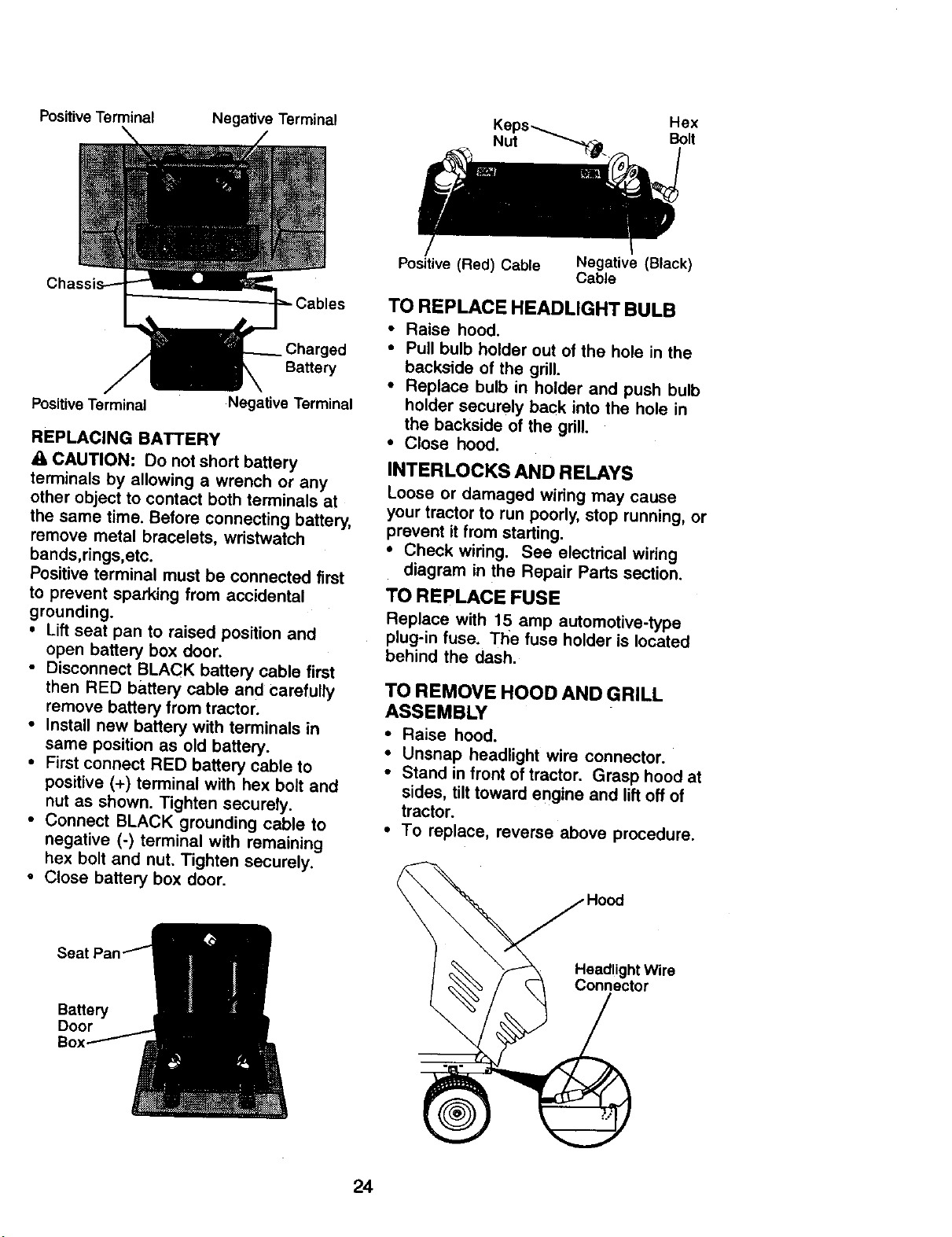
PositiveTerminal Negative Terminal Hex
Nut Bolt
ged
Battery
Positive Terminal
Negative Terminal
REPLACING BATTERY
CAUTION: Do not short battery
terminals by allowing a wrench or any
other object to contact both terminals at
the same time. Before connecting battery,
remove metal bracelets, wristwatch
bands,rings,etc.
Positive terminal must be connected first
to prevent sparking from accidental
grounding.
• Lift seat pan to raised position and
open battery box door.
• Disconnect BLACK battery cable first
then RED battery cable and carefully
remove battery from tractor.
• Install new battery with terminals in
same position as old battery.
• First connect RED battery cable to
positive (+) terminal with hex bolt and
nut as shown. Tighten securely.
• Connect BLACK grounding cable to
negative (-) terminal with remaining
hex bolt and nut. Tighten securely.
• Close battery box door.
Sea I
Battery
Door
Positive (Red) Cable
Negative (Black)
Cable
TO REPLACE HEADLIGHT BULB
• Raise hood.
• Pull bulb holder out of the hole in the
backside of the grill.
• Replace bulb in holder and push bulb
holder securely back into the hole in
the backside of the grill.
• Close hood.
INTERLOCKS AND RELAYS
Loose or damaged wiring may cause
your tractor to run poorly, stop running, or
prevent it from starting.
• Check wiring. See electrical wiring
diagram in the Repair Parts section.
TO REPLACE FUSE
Replace with 15 amp automotive-type
plug-in fuse. The fuse holder is located
behind the dash.
TO REMOVE HOOD AND GRILL
ASSEMBLY
• Raise hood.
• Unsnap headlight wire connector.
• Stand in front of tractor. Grasp hood at
sides, tilt toward engine and lift off of
tractor.
• To replace, reverse above procedure.
.,/Hood
24
Maintenance, repair, or replacement of
the emission control devices and
systems, which are being done at the
customers expense, may be performed
by any non-road engine repair establish-
ment or individual. Warranty repairs must
be performed by an authorized engine
manufacturer's service outlet.
ENGINE
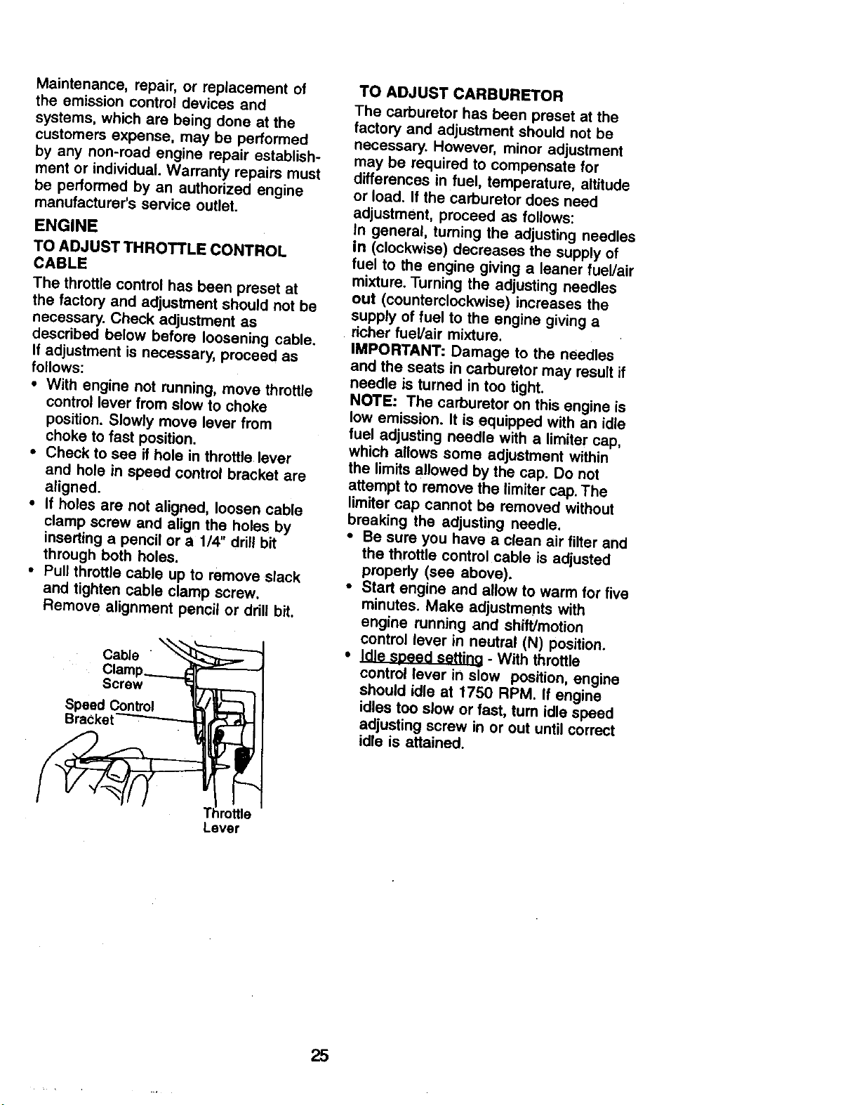
TO ADJUST THROT'FLE CONTROL
CABLE
The throttle control has been preset at
the factory and adjustment should not be
necessary. Check adjustment as
described below before loosening cable.
If adjustment is necessary, proceed as
follows:
• With engine not running, move throttle
control lever from slow to choke
position. Slowly move lever from
choke to fast position.
• Check to see if hole in throttle lever
and hole in speed control bracket are
aligned.
• If holes are not aligned, loosen cable
clamp screw and align the holes by
inserting a pencil or a 1/4" drill bit
through both holes.
• Pull throttle cable up to remove slack
and tighten cable clamp screw.
Remove alignment pencil or drill bit.
Cable "
Clarnp_
Screw r:_
Speed Control _t _ I
Lever
TO ADJUST CARBURETOR
The carburetor has been preset at the
factory and adjustment should not be
necessary. However, minor adjustment
may be required to compensate for
differences in fuel, temperature, altitude
or load. If the carburetor does need
adjustment, proceed as follows:
In general, turning the adjusting needles
in (clockwise) decreases the supply of
fuel to the engine giving a leaner fuel/air
mixture. Turning the adjusting needles
out (counterclockwise) increases the
supply of fuel to the engine giving a
dcher fuel/air mixture.
IMPORTANT: Damage to the needles
and the seats in carburetor may result if
needle is turned in too tight.
NOTE: The carburetor on this engine is
tow emission, it is equipped with an idle
fuel adjusting needle with a limiter cap,
which allows some adjustment within
the limits allowed by the cap. Do not
attempt to remove the limiter cap. The
limiter cap cannot be removed without
breaking the adjusting needle.
• Be sure you have a clean air filter and
the throttle control cable is adjusted
properly (see above).
• Start engine and allow to warm for five
minutes. Make adjustments with
engine running and shift/motion
control lever in neutral (N) position.
• J._ - With throttle
control lever in slow position, engine
should idle at 1750 RPM. If engine
idles too slow or fast, tum idle speed
adjusting screw in or out until correct
idle is attained.
25
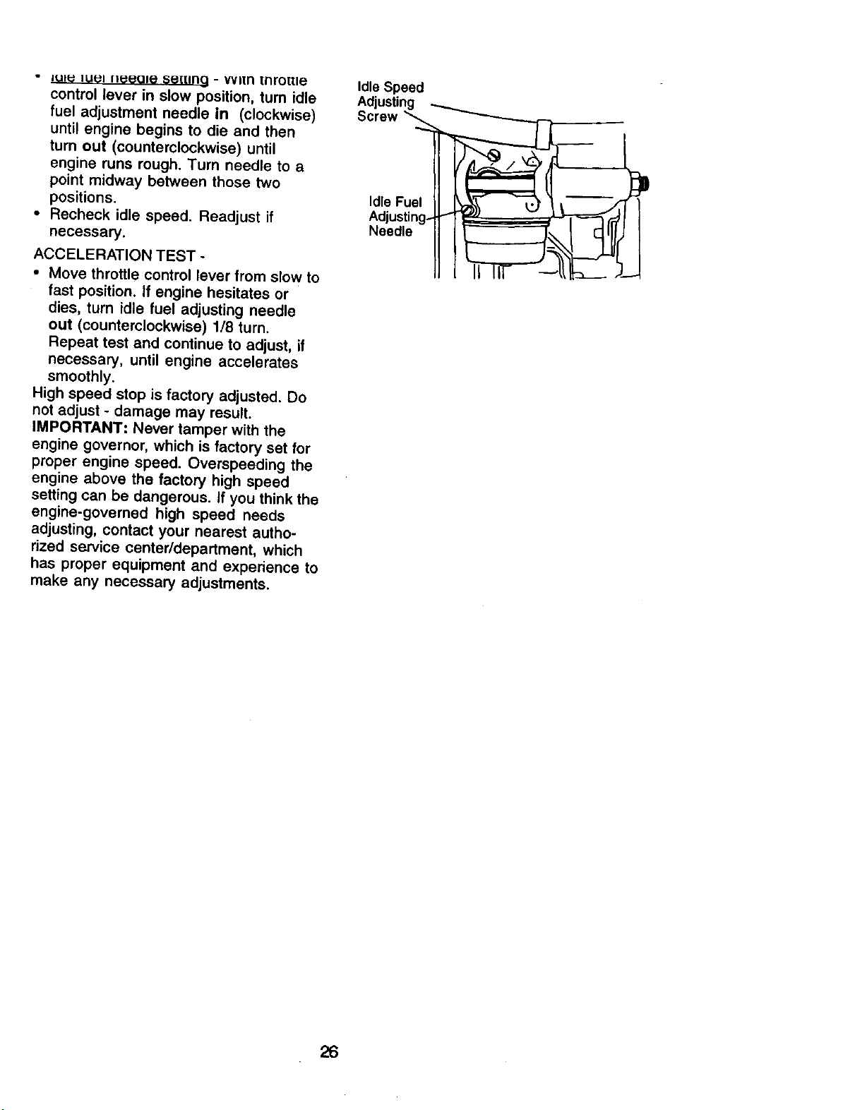
" ILII_ lull I}_eOle S_[[IRQ - VVl[n [nro_le
control lever in slow position, turn idle
fuel adjustment needle in (clockwise)
until engine begins to die and then
turn out (counterclockwise) until
engine runs rough. Turn needle to a
point midway between those two
positions.
• Recheck idle speed. Readjust if
necessary.
ACCELERATION TEST -
• Move throttle control lever from slow to
fast position. If engine hesitates or
dies, turn idle fuel adjusting needle
out (counterclockwise) 1/8 turn.
Repeat test and continue to adjust, if
necessary, until engine accelerates
smoothly.
High speed stop is factory adjusted. Do
not adjust - damage may result.
IMPORTANT: Never tamper with the
engine governor, which is factory set for
proper engine speed. Overspeeding the
engine above the factory high speed
setting can be dangerous. If you think the
engine-governed high speed needs
adjusting, contact your nearest autho-
rized service center/department, which
has proper equipment and experience to
make any necessary adjustments.
Idle Speed
Adjusting
Sore.
Adjeu,_i2g. --
26
Immediately prepare your tractor for
storage at the end of the season or if the
tractor will not be used for 30 days or
more.
_1) CAUTION: Never store the tractor
with gasoline in the tank inside a
building where fumes may reach an
open flame or spark. Allow the engine to
cool before storing in any enclosure.
TRACTOR
Remove mower from tractor for winter
storage. When mower is to be stored for
a period of time, clean it thoroughly,
remove all dirt, grease, leaves, etc. Store
in a clean, dry area.
• Clean entire tractor (See "CLEANING"
in the Maintenance section of this
manual).
• Inspect and replace belts, if necessary
(See belt replacement instructions in
the Service and Adjustments section of
this manual).
• Lubricate as shown in the Mainte-
nance section of this manual.
• Be sure that all nuts, bolts and screws
are securely fastened. Inspect moving
parts for damage, breakage and wear.
Replace if necessary.
• Touch up all rusted or chipped paint
surfaces; sand lightly before painting.
BA'I"rERY
• Fully charge the battery for storage.
• After a period of time in storage,
battery may require recharging.
• To help prevent corrosion and power
leakage during long periods of
storage, battery cables should be
disconnected and battery cleaned
thoroughly (see "TO CLEAN BATTERY
AND TERMINALS" in the Maintenance
section of this manual).
• After cleaning, leave cables discon-
nected and place cables where they
cannot come in contact with battery
terminals.
• If battery is removed from tractor for
storage, do not store battery directly on
concrete or damp surfaces.
ENGINE
FUEL SYSTEM
IMPORTANT: It is important to prevent
]uUmdeposits from forming in essential
el system parts such as carburetor, fuel
filter, fuel hose, or tank during storage.
Also, expedence indicates that alcohol
blended fuels 9caUed gasohol or using
ethanol or methanol) can attract moisture
which leads to separation and formation
of acids during storage. Acidic gas can
damage the fuel system of an engine
while in storage.
• Drain the fuel tank.
• Start the engine and let it run until the
fuel lines and carburetor are empty.
• Never use engine or carburetor
cleaner products in the fuel tank or
permanent damage may occur.
• Use fresh fuel next season.
NOTE: Fuel stabilizer is an acceptable
alternative in minimizing the formation of
fuel gum deposits dudng storage. Add
stabilizer to gasoline in fuel tank or
storage container. Always follow the mix
ratio found on stabilizer container. Run
engine at least 10 minutes after adding
stabilizer to allow the stabilizer to reach
the carburetor. Do not drain the gas tank
and carburetor if using fuel stabilizer.
ENGINE OIL
Drain oil (with engine warm) and replace
with clean engine oil. (See "ENGINE" in
the Maintenance section of this manual).
CYLINDER(S)
• Remove spark plug(s).
• Pour one ounce of oil through spark
plug hole(s) into cylinder(s).
• Turn ignition key to "START" position
for a few seconds to distribute oil.
• Replace with new spark plug(s).
OTHER
• Do not store gasoline from one season
to another.
• Replace your gasoline can if your can
starts to rust. Rust and/or dirt in your
gasoline will cause problems.
• If possible, store your tractor indoors
and cover it to give protection from
dust and dirt.
• Cover your tractor with a suitable
protective cover that does not retain
moisture. Do not use plastic. Plastic
cannot breathe which allows conden-
sation to form and will cause your
tractor to rust.
IMPORTANT: Never cover tractor while
engine and exhaust areas are still
warm.
27
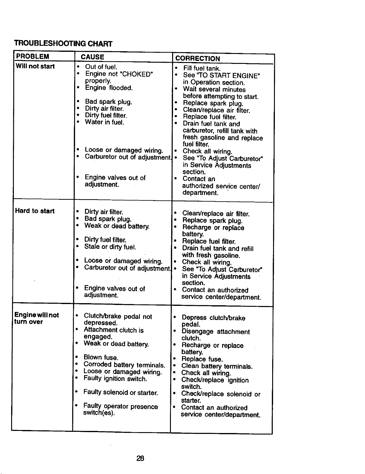
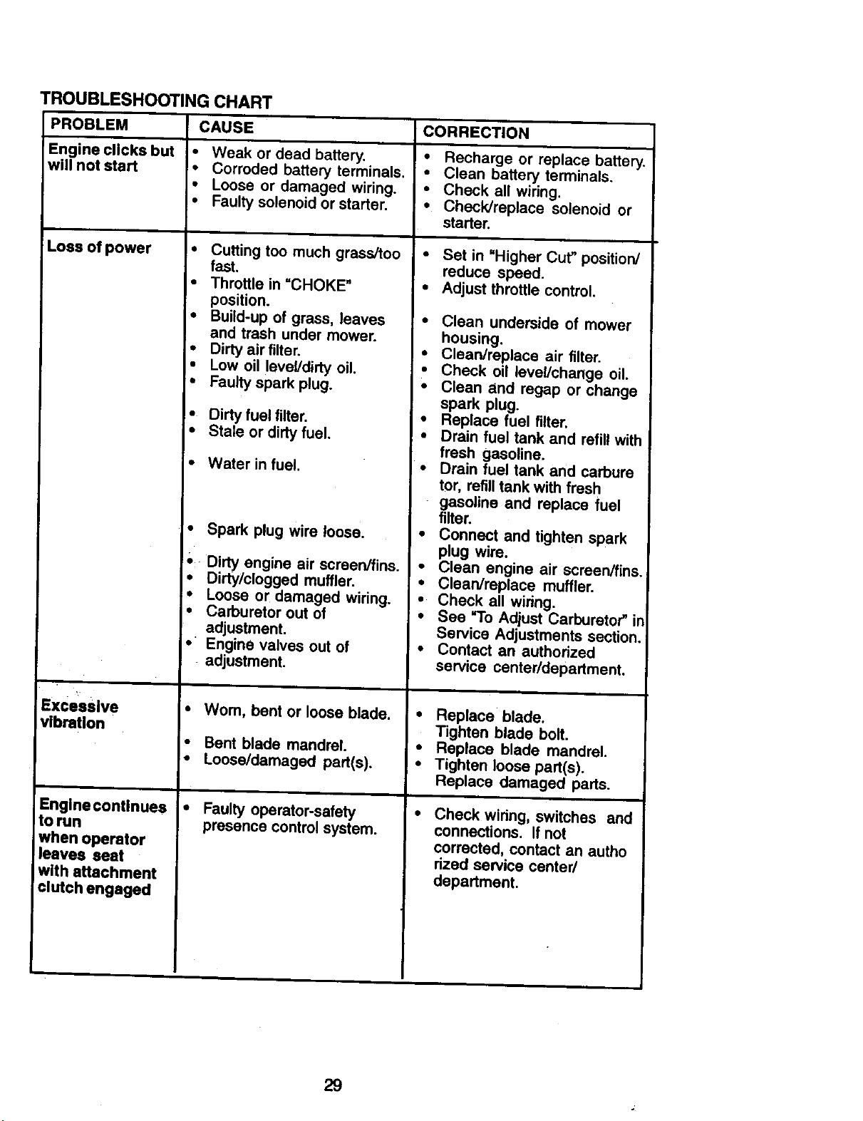
TROUBLESHOOTINGCHART
PROBLEM CAUSE CORRECTION
Will not start
Hard to start
Enginewill not
turn over
• Out of fuel.
• Engine not "CHOKED"
properly.
• Engine flooded.
Bad spark plug.
Dirty air filter.
'- Dirty fuel filter.
• Water in fuel.
• Loose or damaged wiring.
• Carburetor out of adjustment,
• Engine valves out of
adjustment.
• Dirty air filter.
• Bad spark plug.
• Weak or dead battery.
• Dirty fuel filter,
• Stale or dirtyfuel.
• Loose or damaged wiring.
• Carburetor out of adjustment
• Engine valves out of
adjustment.
Clutch/brake pedal not
depressed.
Attachment clutch is
engaged.
Weak or dead battery.
Blown fuse.
Corroded battery terminals.
Loose or damaged wiring.
Faulty ignition switch.
Faulty solenoid or starter.
Faulty operator presence
switoh(es).
• Fill fuel tank.
• See "TO START ENGINE"
in Operation section.
• Wait several minutes
before attempting to start.
• Replace spark plug.
• Clean/replace air filter.
• Replace fuel filter.
• Drain fuel tank and
carburetor, refill tank with
fresh gasoline and replace
fuel filter.
• Check all wiring.
• See "To Adjust Carburetor"
in Service Adjustments
section.
• Contact an
authodzed service center/
department.
• Clean/replace air filter.
• Replace spark plug.
• Recharge or replace
battery.
:• Replace fuel filter.
• Drain fuel tank and refill
with fresh gasoline.
• Check all wiring.
• See "To Adjust Carburetor"
in Service Adjustments
section,
• Contact an authodzed
service center/department.
• Depress clutch/brake
pedal.
• Disengage attachment
clutch.
• Recharge or replace
battery.
• Replace fuse.
• Clean battery terminals.
• Check all wiring.
• Check/replace ignition
switch.
• Check/replace solenoid or
starter,
• Contact an authorized
service center/department.
28
TROUBLESHOOTINGCHART
CAUSE
• Weak or dead battery.
• Corroded battery terminals,
• Loose or damaged wiring.
• Faulty solenoid or starter.
PROBLEM
Engine clicks but
will not start
Loss of power
Excessive
vibration
Engine continues
to run
when operator
leaves seat
with attachment
clutch engaged
• Cutting too much grass/too
fast,
• Throttle in =CHOKE"
position.
• Build-up of grass, leaves
and trash under mower.
• Dirty air filter.
• Low oil level/dirty oil,
• Faulty spark plug.
• Dirty fuel filter.
• Stale or dirty fuel.
• Water in fuel.
• Spark plug wire loose.
• Dirty engine air screen/fins.
• Dirty/clogged muffler.
• Loose or damaged wiring.
• Carburetor out of
adjustment.
• " Engine valves out of
adjustment.
• Worn, bent or loose blade.
• Bent blade mandrel.
• Loose/damaged part(s).
• Faulty operator-safety
presence control system.
CORRECTION
• Recharge or replace battery.
• Clean battery terminals.
• Check all wiring,
• Check/replace solenoid or
starter,
• Set in "Higher Cut" position/
reduce speed.
• Adjust throttle control.
Clean underside of mower
housing.
Clean/replace air filter.
Check oil level/change oil.
Clean and ragap or change
spark plug.
Replace fuel filter.
Drain fuel tank and refill with
fresh gasoline.
Drain fuel tank and carbure
tor, refill tank with fresh
gasoline and replace fuel
filter.
Connect and tighten spark
plug wire.
Clean engine air screen/fins.
Clean/replace muffler.
Check all wiring.
See =To Adjust Carburetor" in
Service Adjustments section.
Contact an authorized
service centerldepartment.
• Replace blade.
Tighten blade bolt.
• Replace blade mandrel.
• Tighten loose part(s).
Replace damaged pads.
Check wiring, switches and
connections, If not
corrected, contact an autho
rized service center/
department.
29
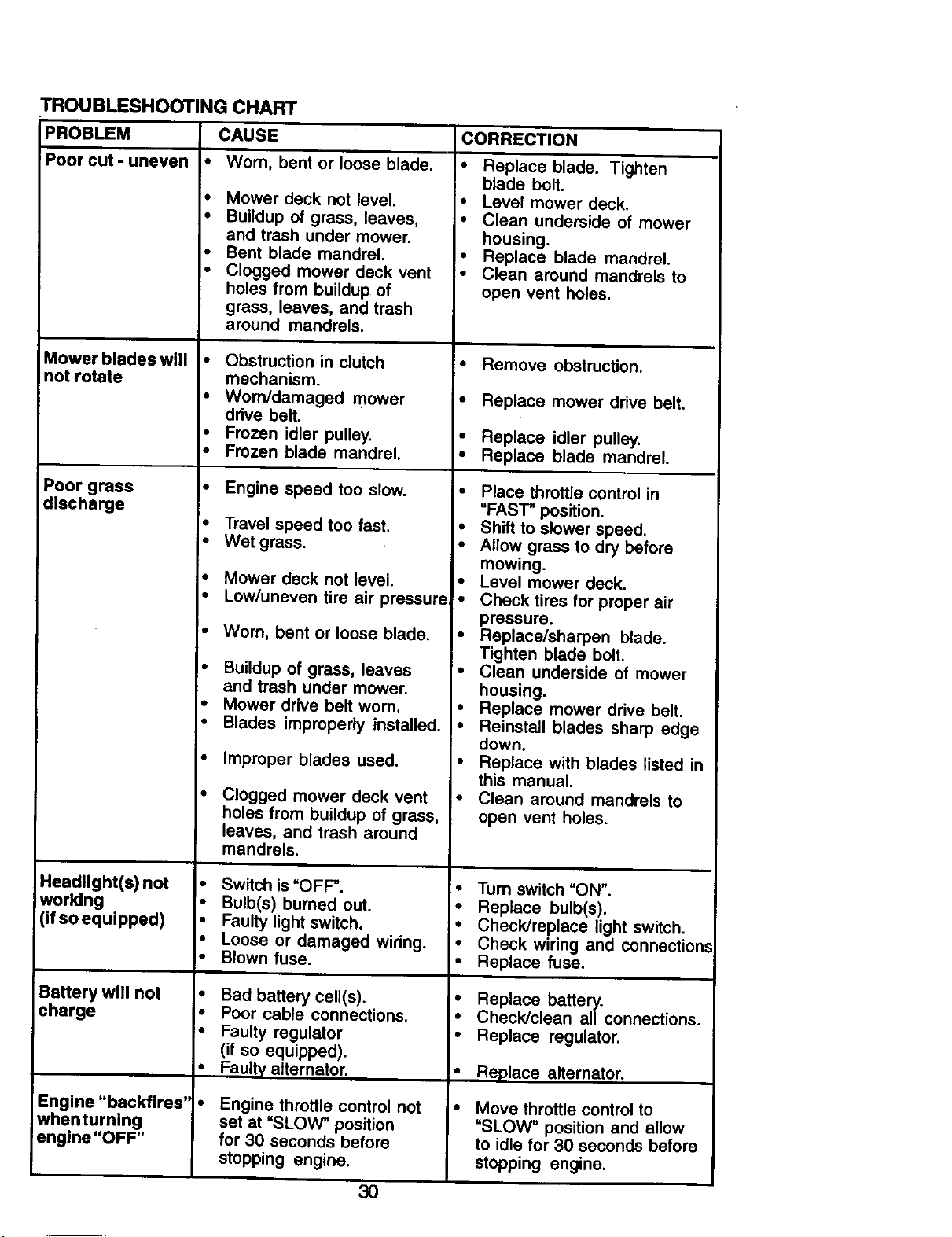
TROUBLESHOOTING CHART
PROBLEM CAUSE
Poor cut - uneven • Worn, bent or loose blade.
Mower blades will
not rotate
Poor grass
discharge
Headlight(s) not •
working
(if so equipped) •
I:
Battery will not •
charge
Engine"backfires' •
whentuming
engine "OFF"
• Mower deck not level.
• Buildup of grass, leaves,
and trash under mower.
• Bent blade mandrel.
• Clogged mower deck vent
holes from buildup of
grass, leaves, and trash
around mandrels.
• Obstruction in clutch
mechanism.
• Worn/damaged mower
drive belt.
• Frozen idler pulley.
• Frozen blade mandrel.
• Engine speed too slow.
• Travel speed too fast.
• Wet grass.
• Mower deck not level.
• Low/uneven tire air pressure
Worn, bent or loose blade.
Buildup of grass, leaves
and trash under mower.
Mower drive belt worn,
Blades improperly installed.
Improper blades used.
Clogged mower deck vent
holes from buildup of grass,
leaves, and trash around
mandrels.
Switch is "OFF".
Bulb(s) burned out.
Faulty light switch.
Loose or damaged wiring.
Blown fuse.
Bad battery cell(s).
Poor cable connections.
Faulty regulator
(if so equipped).
Faulty alternator.
Engine throttle control not
set at "SLOW" position
for 30 seconds before
stopping engine.
CORRECTION
I" Replace blade. Tighten
blade bolt.
• Level mower deck.
• Clean underside of mower
housing.
• Replace blade mandrel.
• Clean around mandrels to
open vent holes.
• Remove obstruction.
• Replace mower drive belt.
• Replace idler pulley.
• Replace blade mandrel.
• Place throttle control in
"FAST" position.
• Shift to slower speed.
• Allow grass to dry before
mowing.
• Level mower deck.
• Check tires for proper air
pressure.
• Replace/sharpen blade.
Tighten blade bolt.
• Clean underside of mower
housing.
• Replace mower drive belt.
• Reinstall blades sharp edge
down.
• Replace with blades listed in
this manual.
Clean around mandrels to
open vent holes.
• Turn switch "ON".
• Replace bulb(s).
• Check/replace light switch.
• Check wiring and connections
• Replace fuse.
• Replace battery.
• Check/clean all connections.
• Replace regulator.
• Replace alternator.
Move throttle control to
=SLOW" position and allow
to idle for 30 seconds before
stopping engine.
3O

TRACTOR -- MODEL NUMBER 917.271072
SCHEMATIC
RED
BATTERY SOLENOID
AMMETER
(OPTIONAL)
FUSE
WHITE
CLUTCH / BRAKE
I (PEDAL UP) ,
l,--I ,
L_O,, : ,_
RED
s
FUEL
L ....... •
,
FUEL SHUT-OFF
_, SOLENOID
SEAT SWITCH
(NOT OCCUPIED)
A3-_MENT CLUTCH
(CLUTCH OFF)
185 86 t
I I I
187 1 30
, _A _
IGNITION SWITCH
POSITION ClRCUff "MAKE" I
OFF k_÷O÷Al NONE
RUN/LIGHT B+A1 A2+L
RUN B÷A1 NONE
START 8+S+A1 NONE
BLLAE
RED
RELAY
(RIEGIKATO R DI_42,_'4NECTE [
OPERATOR _ I
PRESENCE RELAY #3
HEADLIGHTS I
i _7A : I
• o
NON-REMOVABLE REMOVABLE
CONNECTIONS CONNECTIONS
WIRING INSULATED CUPS
NOTE: IF WIRING INSULATED CLIPS WERE REMOVED FOR
SERVICING OF UNIT, THEY SHOULD BE REPLACED TO
PROPERLY SECURE YOUR WIRING.
31
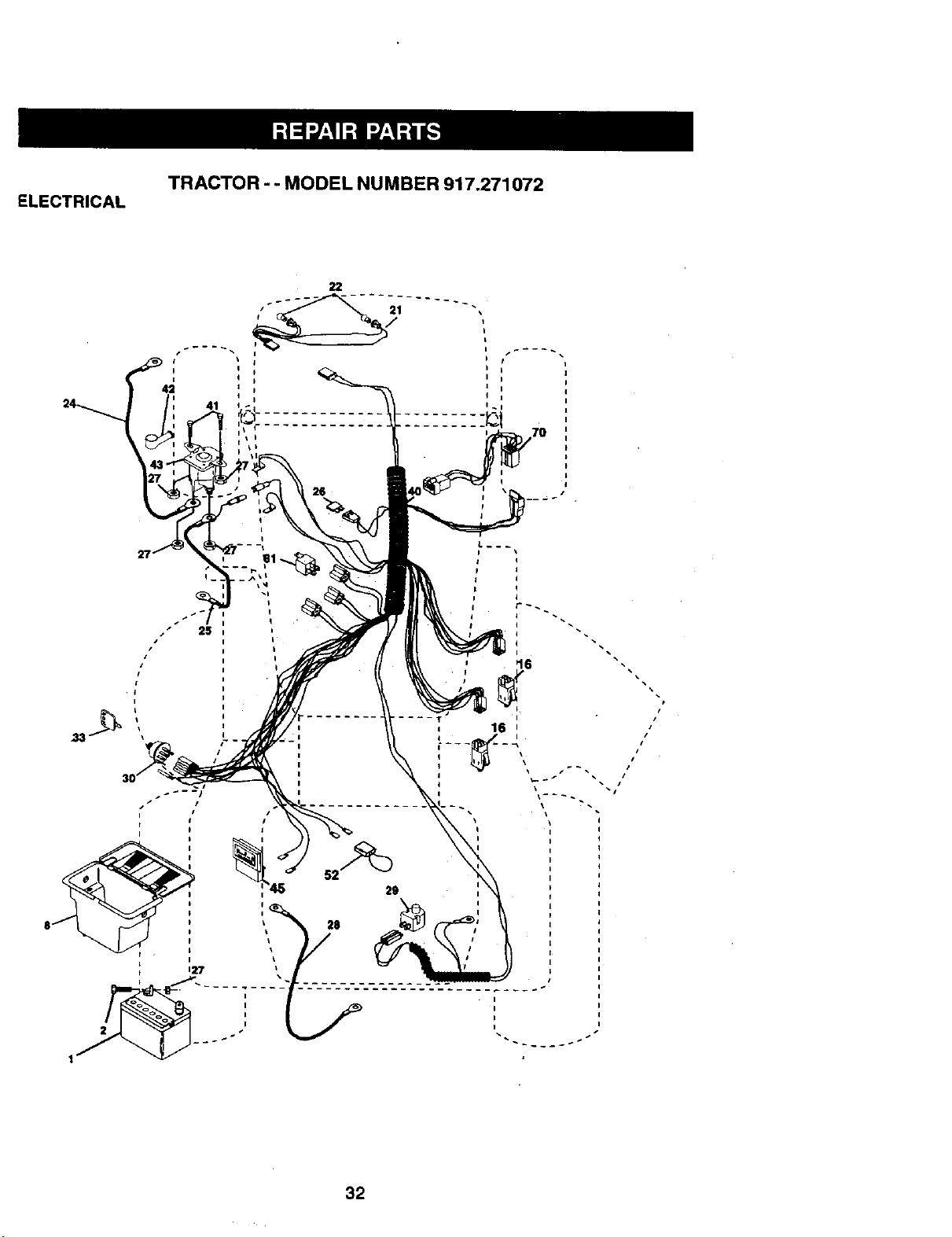
ELECTRICAL
TRACTOR - - MODEL NUMBER 917.271072
22
I
I
4i '
24 41
I
I
I
25
r! i"
45 52
8 I _ 28
i ....
1
I
I
1 I
, 16 i
i \
i
s
i
I
I
32
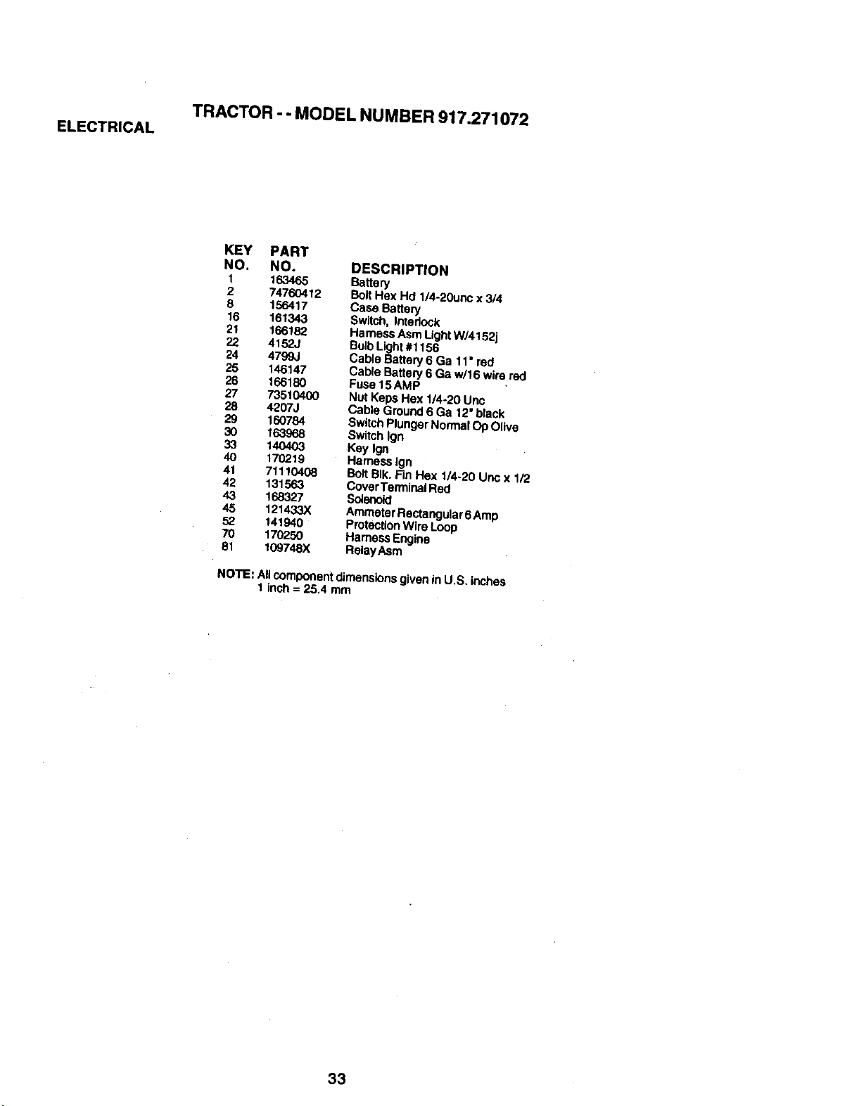
TRACTOR - - MODEL NUMBER 917.271072
ELECTRICAL
KEY PART
NO. NO. DESCRIPTION
I 163465 Battery
2 74760412 BoltHex Hd 1/4-20unc x 3/4
8 156417 Case Battery
16 161343 Switch, Interlock
21 166182 HarnessAsm LightW/4152j
22 4152J BulbLight#1156
24 4799J Cable Battery 6 Ga 11' red
25 146147 Cable Battery 6 Ga w/l 6 wire red
26 166180 Fuse 15AMP
27 73510400 Nut KepsHex 1/4-20 Unc
28 4207J Cable Ground6 Ga 12' black
29 160784 Switch PlungerNormalOp Olive
30 163968 SwitchIgn
33 140403 Key Ign
40 170219 HarnessIgn
41 71"110408 BottBIk. Fin Hex 1/4.20 Uricx 1/2
42 131563 CoverTerminal Red
43 168327 So_erloid
45 121433X AmmeterRectangutar6 Amp
52 141940 ProtecUonWire Loop
70 170250 Hamess Engine
81 109748X RelayAsm
NOTE: Allcomponentdimensionsgivenin U.S. inches
1 inch= 25.4 mm
33
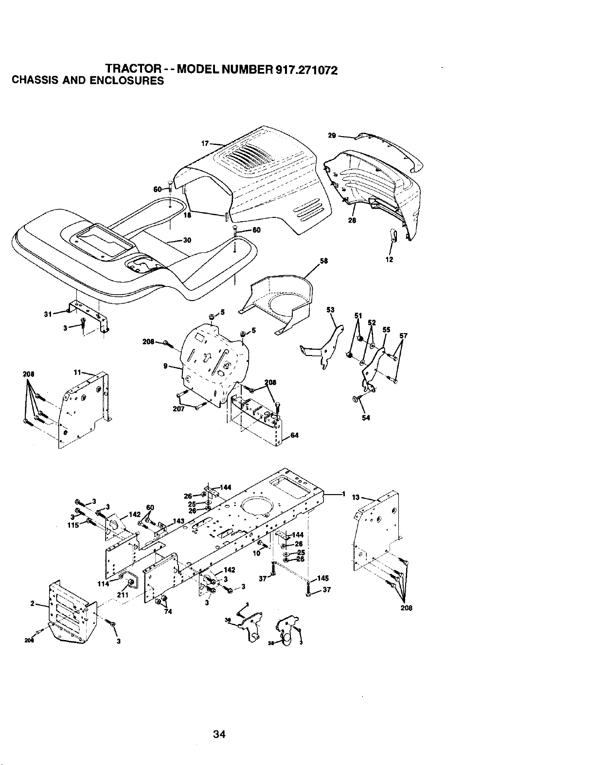
TRACTOR- - MODEL NUMBER 917.271072
CHASSISAND ENCLOSURES
28
58 12
31
53
54
55
211 J
3
74
37
_3
208
34
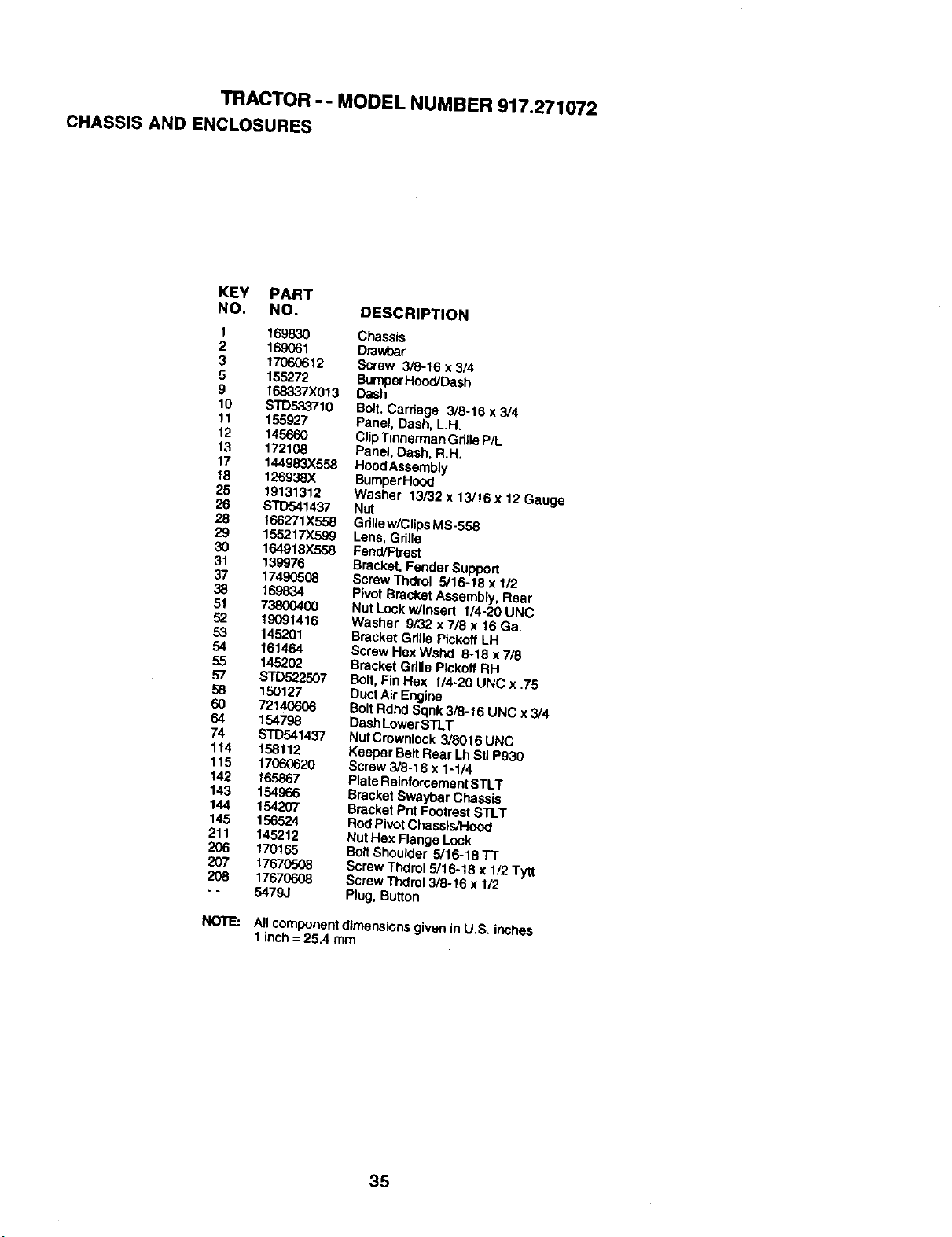
TRACTOR- - MODEL NUMBER 917.271072
CHASSISAND ENCLOSURES
KEY PART
NO. NO. DESCRIPTION
1 169830 Chassis
2 169061 Drawbar
3 17060612 Screw 3/8-16 x 3/4
5 155272 BumperHood,'Dash
9 168337X013 Dash
10 STD533710 Bolt,Carriage 3/8-16 x 3/4
11 155927 Panel, Dash, L.H.
12 145660 ClipTinnermanGdlle P/L
13 172108 Panel, Dash, R.H.
17 144983X558 Hood Assembly
18 126938X BumperH(X_I
25 19131312 Washer 13/32 x 13/16 x 12 Gauge
26 STD541437 Nut
28 166271X558 GriUew/ClipsMS-558
29 155217X599 Lens, Grille
30 164918X558 Fend/Ftrest
31 139976 Bracket, Fender Support
37 17490508 Screw Thdrol 5/16-18 x 1/2
38 169834 Pivot Bracket Assembly, Rear
51 73800400 Nut Lockwllnsert 1/4-20 UNC
52 19091416 Washer 9/32 x 7/8 x 16 Ga.
53 145201 Bracket Gdlle Pickoff LH
54 161464 Screw Hax Wshd 8-18 x 7/6
55 145202 Bracket Gdlle Pickoff RH
57 STD522507 Bolt,Fin Hex 1/4-20 UNC x .75
58 150127 DuctAir Engine
60 72140606 BoltRdhd Sqnk 3/8-16 UNC x 3/4
64 154798 DashLowerSTLT
74 STD541437 Nut Crownlock 3/8016 UNC
114 158112 Keepor BeltRear Lh Stl P930
115 17060620 Screw 3/8-16 x 1-1/4
142 165867 Plate ReinforcementSTL'F
143 154966 Bracket Swaybar Chassis
144 154207 Bracket Pnt Footrest STLT
145 156524 Rod PivotChassis/Hood
211 145212 Nut Hex F_a_je Lock
206 170165 BoltShoulder 5/16-18 TT
207 17670508 Screw Thdrol 5/16-18 x 1/2 Tytt
208 17670608 Scraw Thdrol 3/8-16 x 1/2
- - 5479J Plug, Button
NOTE:
A)Icomponent dimensionsgiven in U.S. inches
1inch = 25.4 mm
35
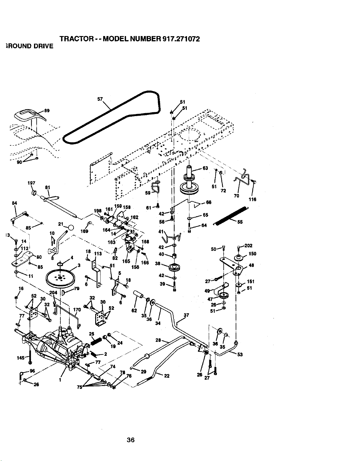
TRACTOR - - MODEL NUMBER 917.271072
;ROUND DRIVE
57
25
i
36
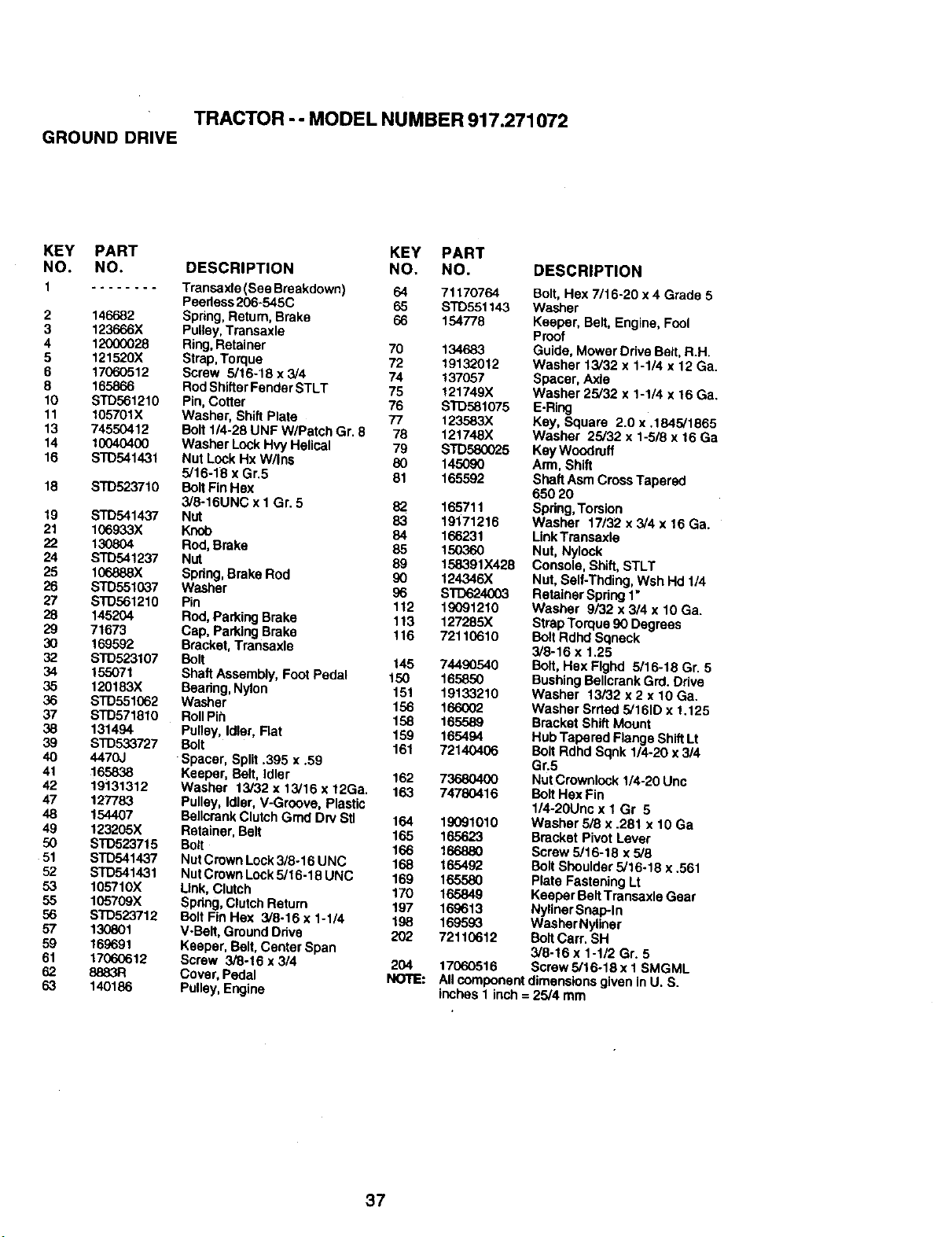
TRACTOR - - MODEL NUMBER 917.271072
GROUND DRIVE
KEY PART KEY PART
NO. NO. DESCRIPTION NO. NO. DESCRIPTION
1 ........ Transaxla (See Breakdown) 64 71170764 Boft, Hex 7/16-20 x 4 Grade 5
Peedess206-545C 65 STD551143 Washer
2 146682 Spring,Return, Brake 66 154778 Keeper, Belt, Engine, Fool
3 123666X Pulley,Transaxle Proof
4 12000028 Ring,Retainer 70 134683 Guide, Mower Odve Bert,R.H.
5 121520X Strap,Torque 72 19132012 Washer 13/32 x 1-1/4 x 12 Ga.
6 17060512 Screw 5/16-18 x 3/4 74 137057 Spacer, Axle
8 165866 RodShiftsrFenderSTLT 75 121749X Washer 25/32 x 1-1/4 x 16 Ga.
10 STD561210 Pin,Cotter 76 STD581075 EoRing
11 105701X Washer, Shift Plate 77 123583X Key, Square 2.0 x .1845/1865
13 74550412 Bolt114-28UNF W/Patch Gr. 8 78 121748X Washer 25/32 x 1-518x 16 Ga
14 10040400 Washer Look HvyHelical 79 STD580025 KeyWoodruff
16 STD541431 Nut LockHx W/Ins 80 145090 Arm, Shift
5/16-18 x Gr.5 81 165592 Shaft AsmCrossTapered
18 STD523710 BoltFinHex 650 20
3/8-16UNC x I Gr. 5 82 165711 Spring,Torsion
19 STD541437 Nut 83 19171216 Washer 17/32 x 3/4 x 16 Ga.
21 106933X Knob 84 166231 LinkTransaxla
22 130804 Rod, Brake 85 150360 Nut, Nylock
24 STD541237 Nut 89 158391X428 Console, Shift, STLT
25 106888X Spring,Brake Rod 90 124346X Nut. Self-Thding, Wsh Hd 1/4
26 STD551037 Washer 96 STD624003 RetainerSpring 1"
27 STD561210 Pin 112 19091210 Washer 9/32 x3/4 x 10 Ga.
28 145204 Rod,Parking Brake 113 127285X StrapTorque 90 Degrees
29 71673 Cap, Parking Brake 116 72110610 Bolt Rdhd Sqneck
30 169592 Bracket,Transaxle 3/8-16 x 1.25
32 STD523107 Bolt 145 74490540 Bolt, Hsx Flghd 5/16-18 Gr. 5
34 155071 Shaft Assembly, Foot Pedal 150 165850 BushingBellcrank Grd.Drive
35 120183X Beadng,Nylon 151 19133210 Washer 13/32 x 2 x 10 Ga.
36 STD551062 Washer 156 166002 Washer Srrted 5/161Dx 1.125
37 STD571810 RollPih 158 165589 Bracket ShiftMount
38 131494 Pulley, Idler, Flat 159 165494 HubTaparad Flange ShiftLt
39 STD533727 Bolt 161 72140406 ButtRdhd Sqnk 1/4-20 x314
40 4470J Spacer, Split .395 x .59 Gr.5
41 ,165838 Keeper, Belt, Idler 162 73680400 Nut Crownlock 1/4-20 Unc
42 19131312 Washer 13/32 x 13/16 x 12Ga. 163 74780416 BoltHex Fin
47 127783 Pulley, Idler, V-Groove, Plastic 1/4-20Unc x 1 Gr 5
48 154407 Boltcrank ClutchGmd Dry Stl 164 19091010 Washer 5/8 x .281 x 10 Ga
49 123205X Retainer, Belt 165 165623 Bracket Pivot Lever
50 STD523715 Bolt 166 166880 Screw 5/16-16 x 5/8
51 STD541437 NutCrown Lock3/8-16 UNC 168 165492 Bolt Shoulder 5/16o18 x .561
52 SJD541431 NutCrown Lock5/16-18 UNC 169 165580 Plate Fastening Lt
53 105710X Link,Clutch 170 165849 Keeper BeltTransaxle Gear
55 105709X Spring,Clutch Return 197 169613 NylinerSnap-In
56 S'1"D523712 Bolt Fin Hex 3/8-16 x 1-1/4 198 169593 WasherNyliner
57 130801 V-Betl, GroundDrive 202 72110612 Bolt Carr. SH
59 169691 Keeper, Belt, Center Span 3/8-16 x 1-1/2 Gr. 5
61 17060612 Screw 3/8-16 x 3/4 204 17060516 Scraw5/16-18x1 SMGML
62 8883R Cover, Pedal NOTE: All component dimensionsgiven inU. S.
63 140186 Putlay,Engine inches 1 inch = 25/4 mm
37
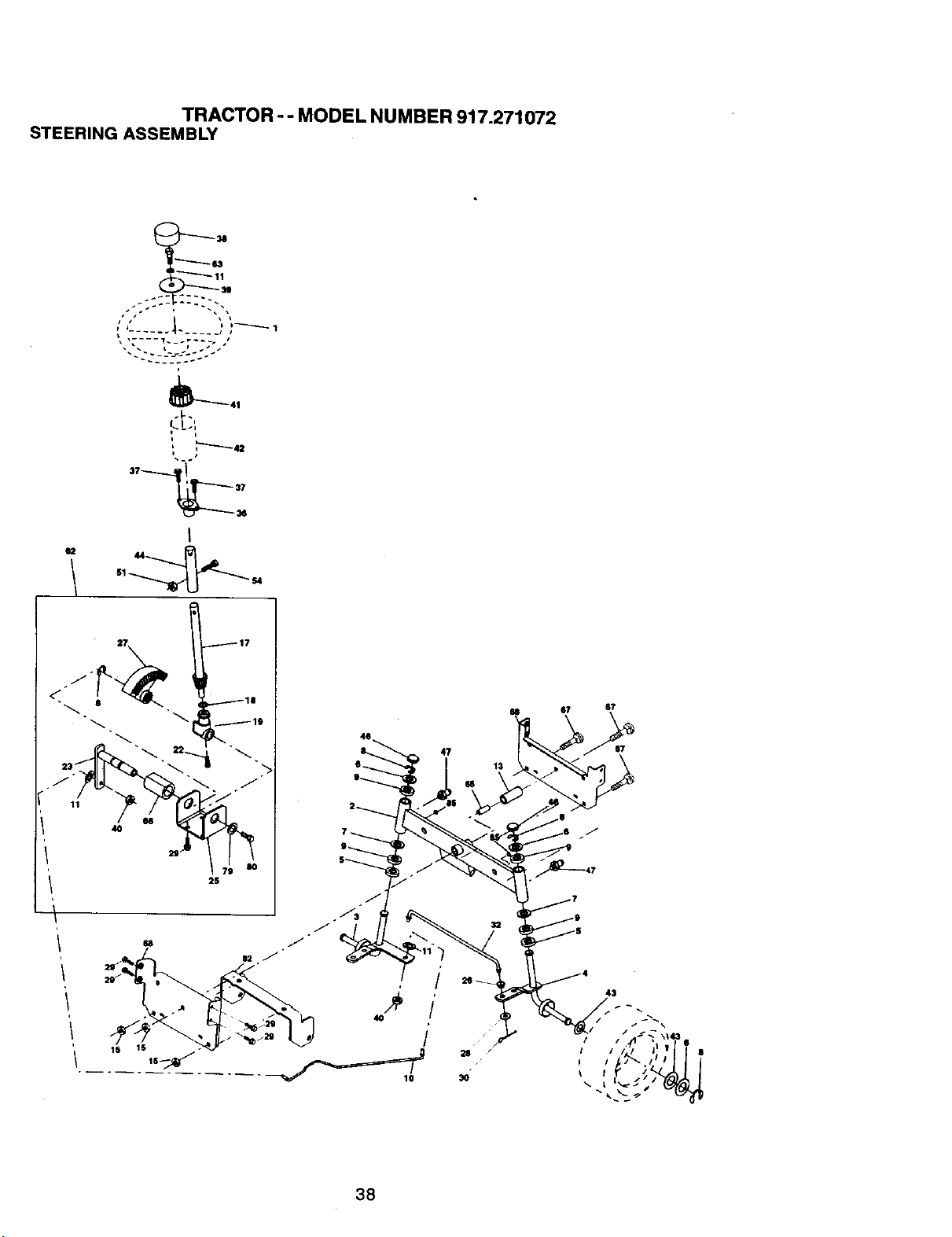
TRACTOR -- MODEL NUMBER 917.271072
STEERINGASSEMBLY
I
112 44
1S
47
67 $7
S7
43
/ f _ \143
/ / IX 16
/ // 8
38

TRACTOR - - MODEL NUMBER 917.271072
STEERING ASSEMBLY
KEY PART
NO. NO. DESCRIPTION
1 139768
2 154427
3 169_40
4 169839
5 6266H
6 .121748X
7 19272016
8 1200O029
9 3366R
10 169832
11 STD551137
t3 136518
,15 145212
17 156546
18 57079
19 160395
22 165857
23 165851
25 1544O6
26 126847X
27 136874
28 19'131416
29 17060612
30 STD561210
32 130465
36 155099
37 152927
38 139769
39 19133812
40 STD5415,37
41 100711L
42 145054X426
43 121749X
44 153720
46 121232X
47 6856M
51 STD541431
54 74780520
62 167902
63 STD523710
65 160367
66 154404
67 72140616
68 169829
79 19132012
80 74950612
82 169835
85 133835
NOTE:
S,1eedngWheel
AxteAssemblySTMP DroppedSTL
Spindle Assembly, L.H.
SpindleAssembly, R.H.
Beadng, Race, ThnJst,Hardened
Washer 25/32 x 1-5/8 x 16 Gauge
Washer 27/32 x 1-1/4 x 16 Gauge
Ring,Klip
Bearing,SteeringColumn
Dragtink
Washer, Lock
Spacer Bearing Axle Front
Nut, Hex Flange Lock
Shaft Assembly, Steering
Washer, Thrust .515 x .750 x .033
Support, Shaft
Screw, Hex Wsh HdTorx
Plttman Shaft Assembly
Bracket, Steering
Bushing, Link,Drag
Gear, Sector
Washer 13/32 x 7/8 x 16 Gauge
Screw 3/6-16 x 3/4
PinCotter
Rod,Tie
Bushing, Steering
Screw
Insert, Steering Wheel
Washer 13/32 x 2-3/8 x 12 Gauge
Nut LockCenter 3/8_24 Un,1
Adaptor,SteeringWheel
Boot, Steering Shaft
Washer 25/32 x 1-1/4 x 16 Gauge
Extension Shaft Steering LR.LT
Cap, Spindle
Fitting,Grease
Nut LockHex w/Ins. 5/16-18 UNC
BoltFin Hex 5/16-18 UNC x 1-1/4
Kit Steering Asm Service
Bolt, Fin Hex 3/8.16 UNC x 1 Gr5
Spacer Brace Axle
BearingArm Pittman
BoltRDHD Sqnk 3/8-16 x 2-1/4
Axle, Brace
Washer 13/32 x 1-1/4 x 12 Ca.
BoltHex Nylon 3/6-16 x 3/4
Bracket Susp. Chassis Front
Fastener ChristmasTree
All component dimensions given in U.S. inches
1inch = 25.4 mm
39
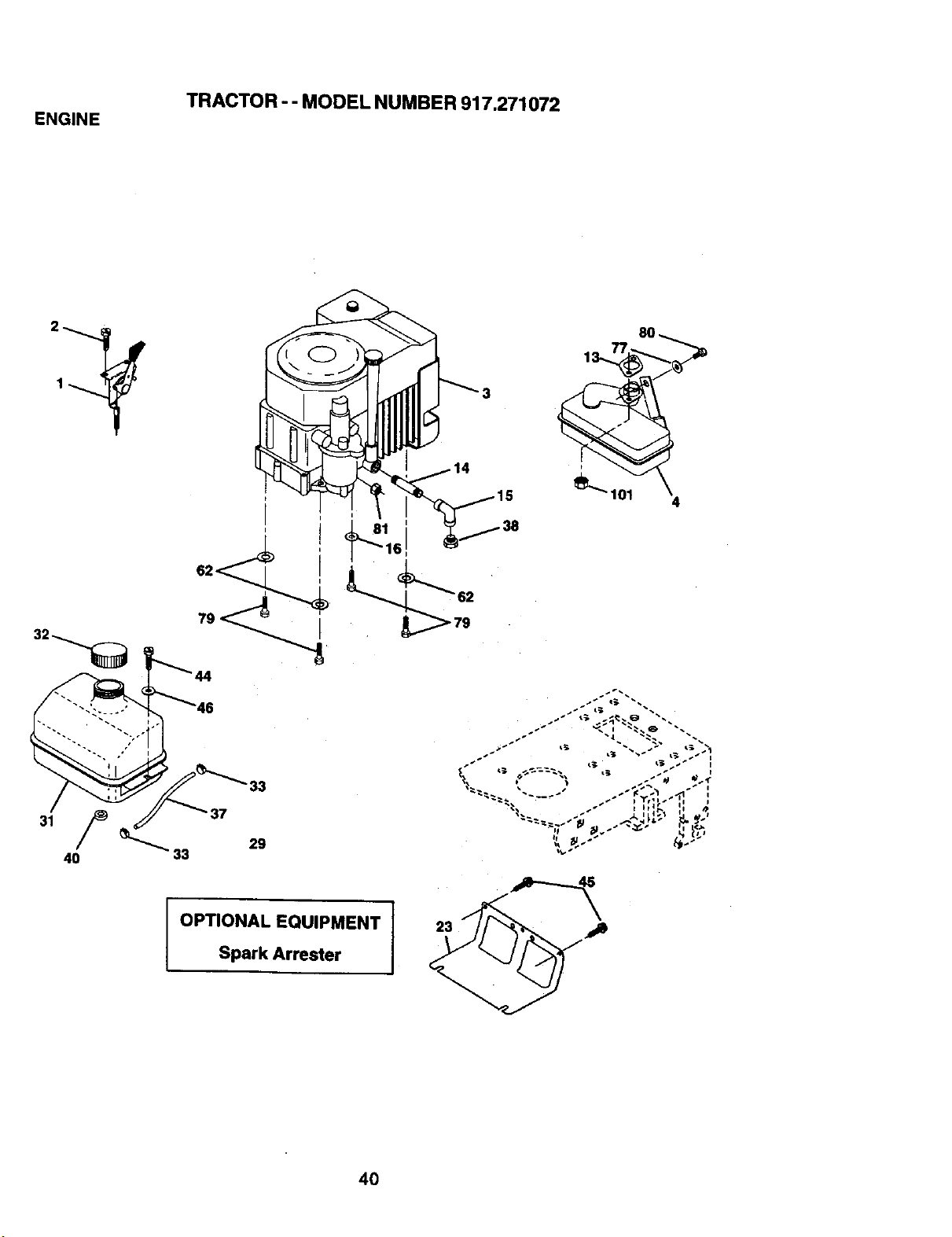
TRACTOR-- MODEL NUMBER 917.271072
ENGINE
t
I
I
79 _
33
29
OPTIONAL EQUIPMENT
Spark Arrester
8O
4O
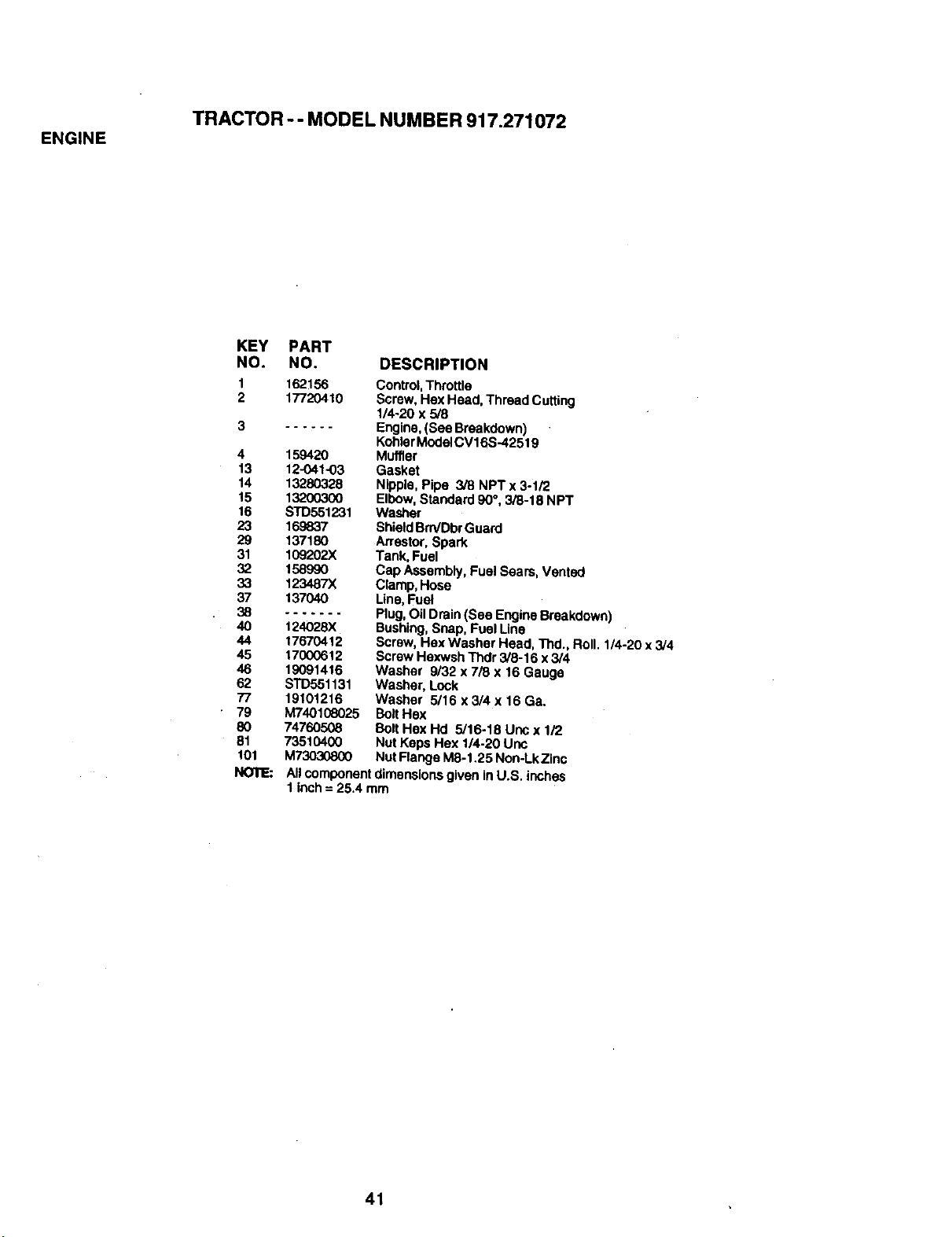
TRACTOR -- MODEL NUMBER 917.271072
ENGINE
KEY PART
NO. NO.
1 1621_
2 17720410
4 159420
13 12-O41-03
14 13280328
15 13200300
16 STD551231
23 169837
29 137180
31 109202X
32 I_990
33 123487X
37 137040
38 .......
40 124028X
44 17670412
45 17000612
46 19091416
62 STD551131
77 19101216
79 M740108025
80 74760508
81 73510400
101 M73030800
NOTE:
DESCRIPTION
Control,Throttle
Screw, Hex Head, Thread Cutting
1/4-20 x 5/8
Engine,(See Breakdown)
KohlarModelCV16S-42519
Muffler
Gasket
Nipple, Pipe 3/8 NPTx 3-1/2
Elbow,Standard 90°, 3/8-18 NPT
Washer
ShieldBrn/DbrGuard
Arrestor,Spark
Tank, Fuel
Cap Assembly, Fuel Sears, Vented
Clamp, Hose
Line,Fuel
Plug,Oil Drain (See EngineBreakdown)
Bushing,Snap, FuelLine
Screw, Hex Washer Head, Thd., Roll. 1/4-20 x 3/4
ScrewHexwsh Thdr 3/8-16 x 3/4
Washer 9/32 x 7/8 x 16 Gauge
Washer, Lock
Washer 5/16 x3/4 x 16 Ga.
BoltHex
Bolt Hex Hd 5/16-18 Unc x 1/2
Nut Keps Hex 1/4:20 Unc
Nut Range M8-1,25 Non-LkZinc
Allcomponent dimensions given inU.S. inches
1 inch= 25.4 mm
41
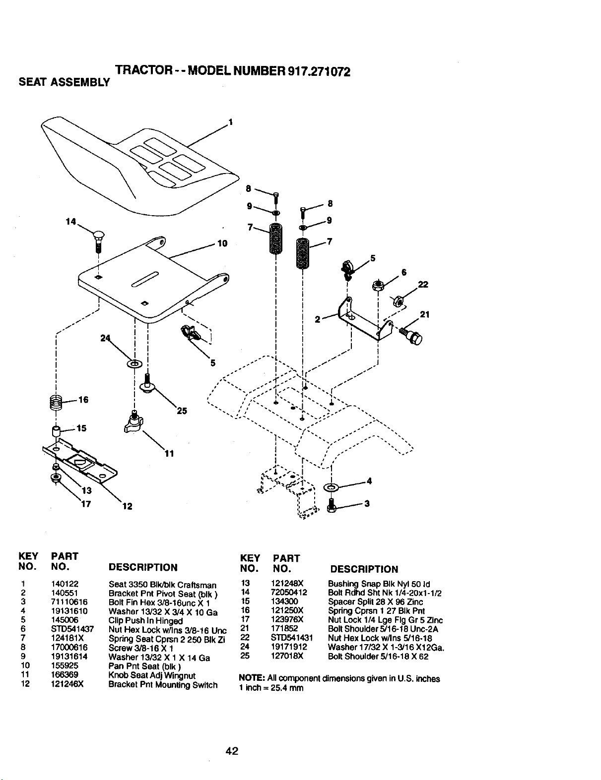
TRACTOR -- MODEL NUMBER917.271072
SEATASSEMBLY
KEY PART KEY PART
NO. NO, DESCRIPTION NO. NO.
1 140122 Seat 3350 Blk/btkCra(tsman 13 121248X
2 140551 Bracket Pnt Pivot Seat (blk) 14 72050412
3 71110616 BoltFin Hex 3/8-16unc X 1 15 134300
4 19131610 Washer 13/32 X 3/4 X 10 Ga 16 121250X
5 145006 Clip Push In Hinged 17 123976X
6 STD541437 Nut Hex Lockw/Ins 3/0-16 Uric 21 171852
7 124181X Spdng Seat Cprsn 2 250 BIkZi 22 STD541431
8 17000616 Screw 3/8-16 X 1 24 19171912
9 19131614 Washer 13/32 X 1 X 14 Ga 25 127018X
10 155925 Pan Pnt Seat (blk)
11 166369 KnobSeat Adj Wingnut
12 121246X Bracket Pnt MountingSwitch
DESCRIPTION
BushingSnap BIk Nyl50 Id
Bolt Rdhd Sht Nk 1/4-20x1-1/2
Spacer Split28 X 96 Zinc
Spring Cprsn 1 27 BIkPnt
Nut Lock 1/4 Lge Fig Gr 5 Zinc
BoltShoulder5/16-18 Unc-2A
Nut Hex Lock w/Ins 5/16-18
Washer 17132X 1-3/16 X12Ga.
Bolt Shoulder5/16-18 X 62
NOTE: All componentdimensionsgivenin U.S. inches
1inch :=25,4 mm
42
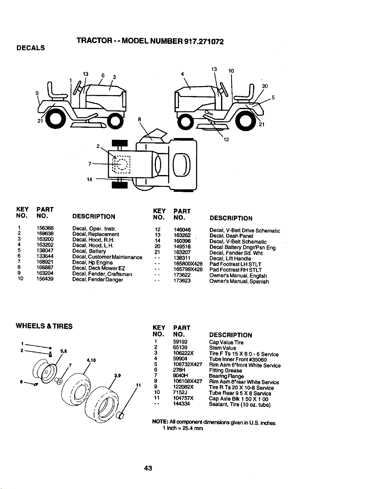
TRACTOR - - MODEL NUMBER 917.271072
DECALS
13 6
3
4
13 10
20
21
8
12
KEY PART
NO. NO.
1 156368
2 169638
3 163200
4 163202
5 138047
6 133644
7 168921
8 166887
9 163204
10 156439
KEY PART
DESCRIPTION NO. NO.
Decal, Oper. InStr. 12 146046
Decal,Replacement 13 163262
Decal,Hood, R.H. 14 160396
Decal, Hood,LH. 20 149516
Decal, Battery 21 163207
Decal,CustomerMaintenance - - 138311
Decal, tip Engine .- 165800X428
Decal, Deck MowerEZ .- 165799X428
Decal, Fender.Craftsman - - 173622
Decal,FenderDanger - - 173623
DESCRIPTION
Decal, V-Belt Drive Schematic
Decal, Dash Panel
Decal, V-Belt Schematic
Decal Battery Dngr/Psn Eng
Decal, Fender Sd.Wht
Decal, LiftHandle
Pad FootrestLH STLT
Pad FootrestRH STLT
Owner's Manual, English
Owner's Manual, Spanish
WHEELS & TIRES
2 _ 5,8
4,10
KEY PART
NO. NO.
1 59192
2 65139
3 106222X
4 59904
5 106732X427
6 278H
7 90401"1
8 106108X427
11 9 122082X
10 7152J
11 I04757X
-- 144334
DESCRIPTION
Cap Value Tire
StemValue
Tire F Ts 15 X 6 0- 6 Service
Tube Inner Front#35060
Rim Asm 6"1fontWhite Service
FittingGrease
BeadngRange
RimAsm 8"rear White Service
Tire R Ts 20 X 10-8 Service
Tube Rear 9 5 X 8 Service
Cap Axle BIk 1 50 X 1 00
Sealant, Tire (10 oz. tube)
NOTE: AllcomponentdimensionsgiveninU.S. inches
1 inch = 25.4 mm
43
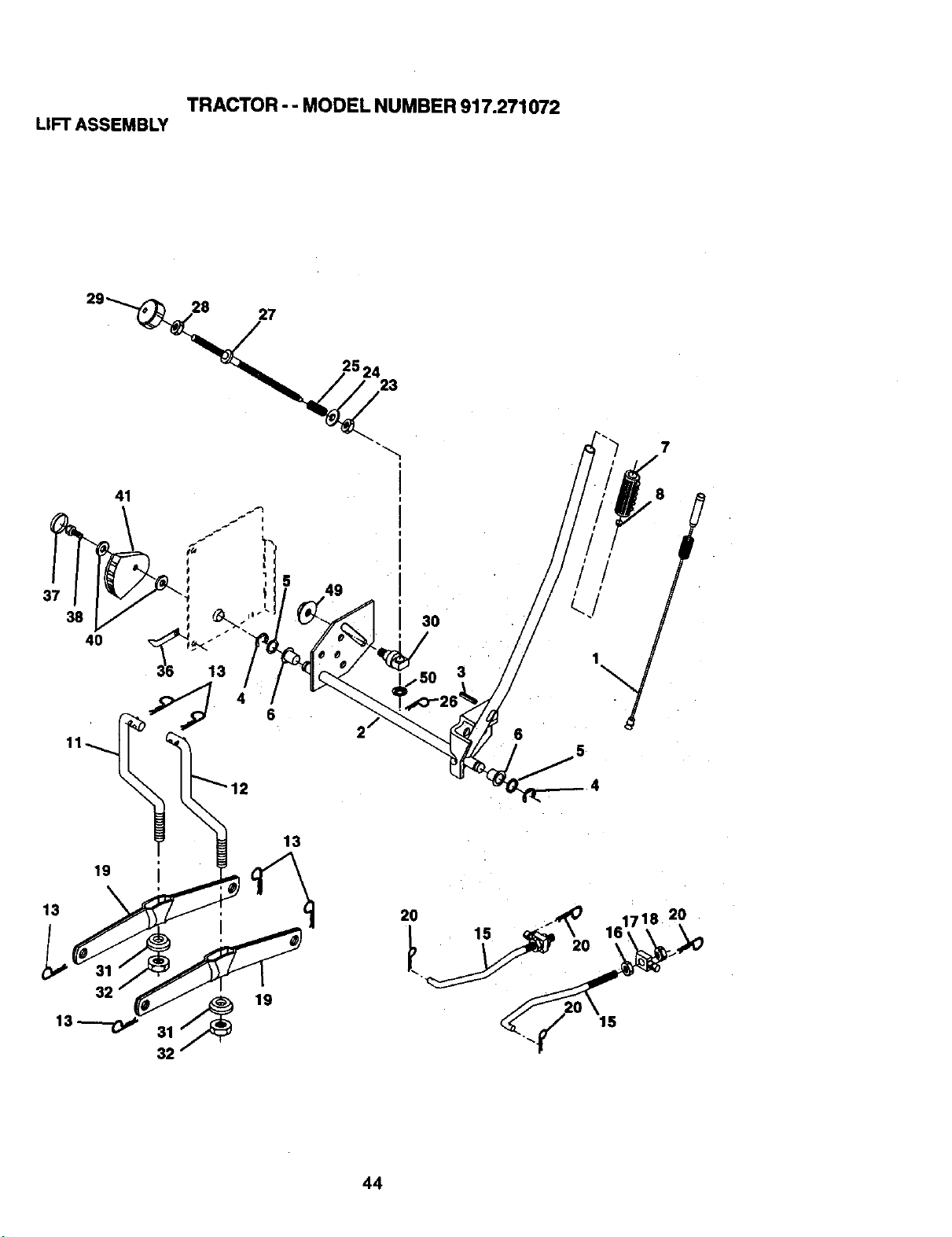
TRACTOR - - MODEL NUMBER 917.271072
LIFTASSEMBLY
27
23
7
49
30
3
6
2O
15
44
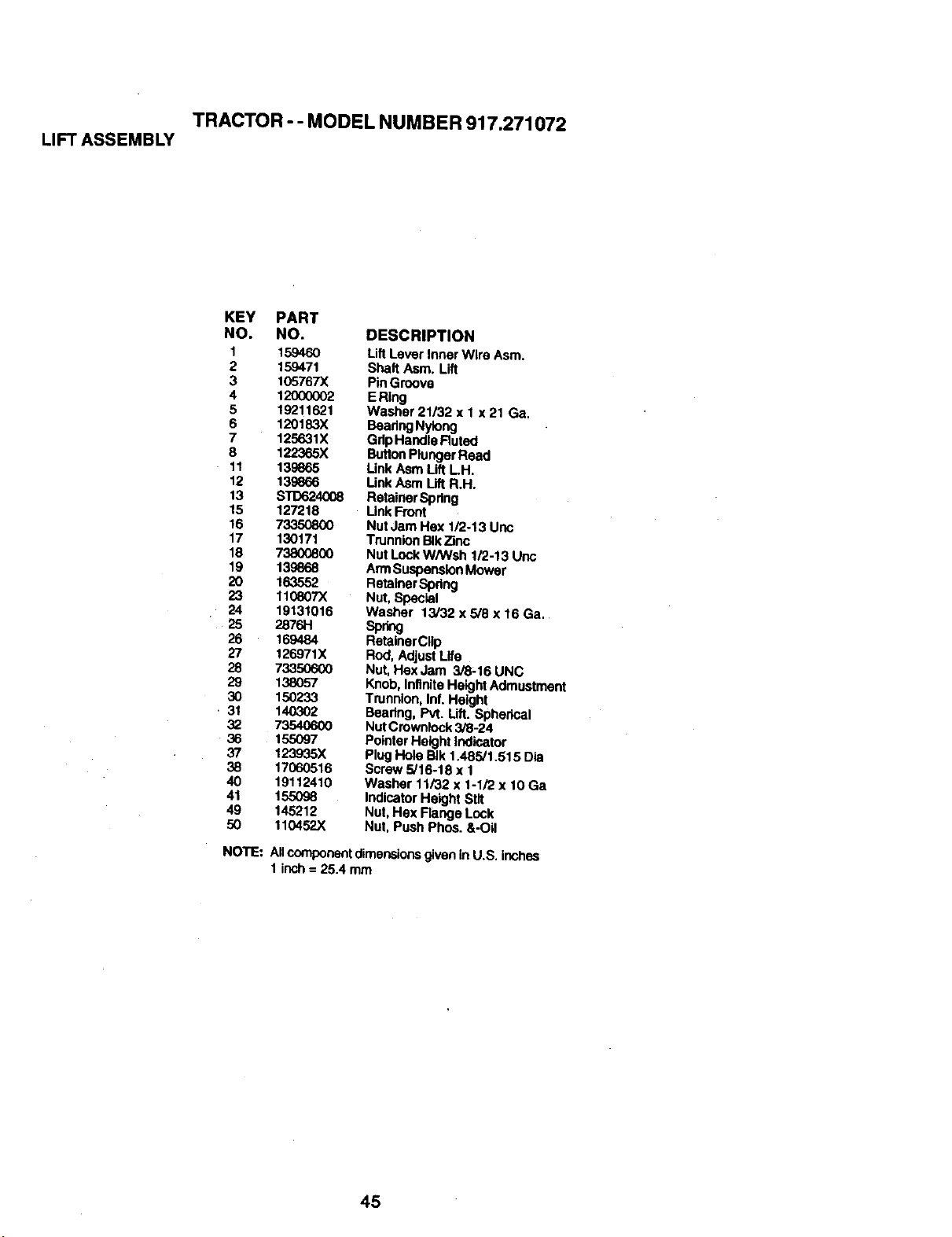
TRACTOR - - MODEL NUMBER 917.271072
LIFTASSEMBLY
KEY PART
NO. NO. DESCRIPTION
1 159460 LiftLever Inner Wire Asm.
2 159471 Shaft Asm. Lift
3 105767X PinGroove
4 12000002 ERing
5 19211621 Washer 21/32 x 1 x 21 Ga,
6 120183X BeadngNylong
7 125631X GdpHandia Ruted
8 122365X ButtonPlungerRead
11 139665 LinkAsm Lift LH.
12 139866 Unk Asm Lift R.H.
13 SXD624_08 Rata'marSpring
15 127218 Unk Front
16 73350800 Nut Jam Hex 1/2o13 Uoc
17 130171 Tn_nnionB_k_nc
18 73800800 Nut LockW/Wsh 1/2-13 Unc
19 139868 ArmSuspensionMower
20 163552 Retainer Sp_
23 110807X Nut, Special
24 19131016 Washer 13/32 x 5/8 x 16 Ga.
26 169484 RetalnerCllp
27 126971X Rod, AdjustLife
28 73350600 Nut, HexJam 3/8-16 UNC
29 138057 Knob,InfiniteHeight Admustment
30 150233 Trunnion, Inf. Height
31 140302 Bearing, Pvt. Lift. Spherical
32 73540600 NutCi'ownlock3/8-24
36 155097 PointerHeight Indicator
37 123935X Plug Hole BIk 1.485/1.515 Dia
38 17060516 Screw 5/16-18 x 1
40 19112410 Washer 11/32 x 1-1/2 x 10 Ga
41 155098 IndicatorHeight Stif
49 145212 Nut, Hex Range Lock
50 110452X Nut, Push Phos. &-Oil
NOTE:
Artcomponentdimensionsgivenin U.S. inches
1inch = 25.4 mm
45
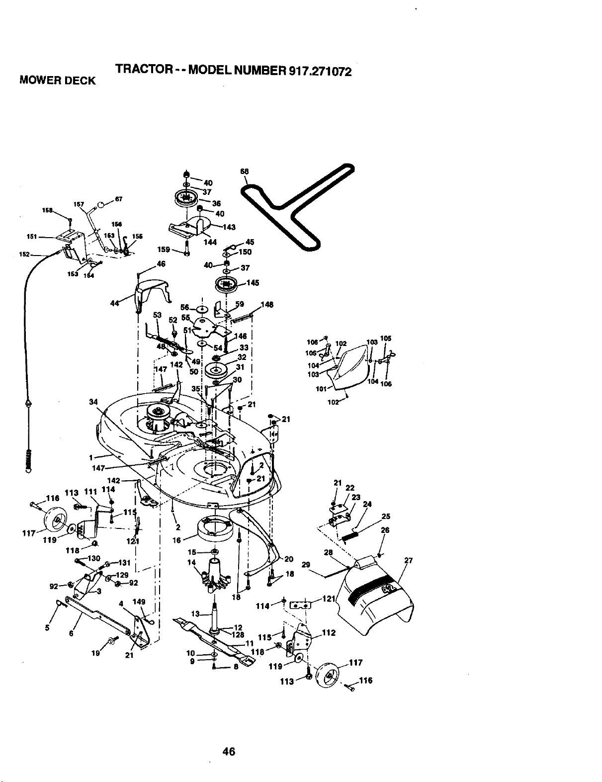
TRACTOR -- MODEL NUMBER 917.271072
MOWER DECK
27
46
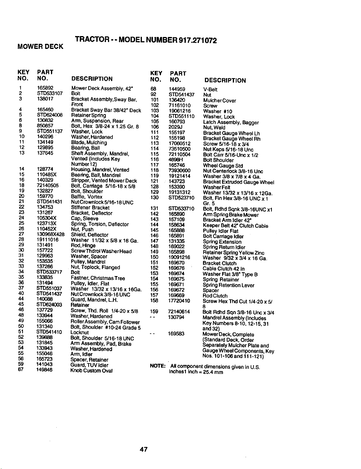
TRACTOR -- MODEL NUMBER 917.271072
MOWERDECK
KEY PART
NO. NO.
1 165892
2 STD533107
3 138017
4 165460
5 STD624008
6 13O832
8 850857
9 STD551137
10 140296
11 134149
12 129895
13 137645
14 128774
15 110485X
16 140329
18 72140505
19 132827
20 159770
21 STD541431
22 134753
23 131267
24 105304X
25 123713X
26 110452X
27 130968X428
28 19111016
29 131491
30 157722
31 129963
32 153535
33 137266
34 STD533717
35 133835
36 131494
37 STD551(_7
40 STD541437
44 140088
45 STD624003
46 137729
48 133944
49 155066
50 131340
51 ST0541410
52 139888
53 131845
54 133943
55 155046
56 165723
59 141043
67 149846
KEY PART
DESCRIPTION NO. NO. DESCRIPTION
Mower Deck Assembly,42" 68 144959
Bolt 92 STD541437
Bracket Assembly,Sway Bar, 101 136420
Front 102 71161010
Bracket Sway Bar 38/42" Deck 103 19061216
Retainer Spdng 104 STD551110
Arm, Susper_sk_, Rear 105 160793
Bolt, Hex 3/8-24 x 1.25 Gr. 8 106 2029J
Washer, Lock 111 155197
Washer, Hardened 112 155198
Blade, Mulching 113 17060512
Beadng, Ball 114 73510500
Shaft Assembly, Mandrel, 115 72110504
Vented (Includes Key 116 4896H
Number12) 117 165746
Housing,Mandrel, Vented 118 73930600
Beadng,Bail, Mandrel 119 19121414
Stripper,Vented Mower Deck 121 143723
Bolt,Carriage 5/16-18 x 5/8 128 153390
Bolt,Shoulder 129 19131312
Baffle, Vodex 130 STD523710
Nut Crownlock5/16-18 UNC
StiffenerBracket 131 STD533710
Bracket, Deflector 142 165890
Cap, Sleeve 143 157109
Spdng,Torsion, Deflector 144 158634
Nut, Push 145 165888
Shield, Deflector 146 165891
Washer 11/32 x 5/8 x 16 Ga. 147 131335
Red, Hinge 148 169022
ScrewThdrolWasher Head 149 165898
Washer, Spacer 150 19091216
Pulley,Mandrel 151 169670
Nut,Toplock, Flanged 152 169676
Bolt 153 169674
Fastner, ChristmasTree 154 169675
Pulley, Idler, Flat 155 169671
Washer 13/32 x 13/16 x 16Ga. 156 169672
Nut Crownlock3/8.16 UNC 157 169669
Guard, Mandrel, L.H. 158 17720410
Retainer
Screw, Thd. Roll 1/4-20 x 5/8 159 72140614
Washer, Hardened - - 130794
RotterAssembly,Cam Follower
Bolt,Shoulder #10-24 Grade 5
Locknut - • 169583
Bolt,Shoulder 5/16-18 UNC
Arm Assembly, Pad, Brake
Washer,Hardened
Arm, Idler
Spacer, Retainer
Guard, TUVIdler
KnobCustomOval
V-Belt
Nut
MulcherCover
Screw
Washer #10
Washer, Lock
Latch Assembly, Bagger
Nut,Weld
Bracket Gauge Wheel Lh
Bracket Gauge Wheel Rh
Screw 5/16-18 x3/4
Nut Keps 5/16-18 Unc
Bolt Carr 5/16-Unc x 1/2
Bolt Shoulder
Wheel Gauge Std
Nut Centerlock 3/8-16 Unc
Washer 3/8 x 7/8 x 4 Ga.
Bracket ExtrudedGauge Whee_
Washer Felt
Washer 13/32 x 13/16 x 12Ga.
Bolt, Fin Hex 3/8-16 UNC x 1
Gr. 5
Bolt, Rdhd Sqnk 3/8-16UNC xl
Arm SpdngBrake Mower
Bracket Arm Idler 42"
Keeper Belt42" ClutchCable
Pulley Idler Flat
BoltCarriage Idler
Spring Extension
Spring Return Idler
Retainer SpringYellowZinc
Washer 9/32 x 3/4 x 16 Ga
Bracket Clutch
Cable Clutch42 In
Washer Flat 3/8" Type B
Spdng Retainer
SpringRetention Lever
Spacer
RodClutch
Screw Hex Thd Cut 114-20x 5/
8
BoltRdhd Sqn 3/8-16 Unc x 3/4
MandrelAssembly (Includes
Key Numbers 8-10, 12-15, 31
and 32)
Mower Deck, Complete
(Standard Deck, Order
Separately MulcherPlate and
Gauge Wheel Components, Key
Nos. 101-106and 111-121)
NOTE: All component dimensionsgiven in U.S.
inches1inch = 25.4 mm
47
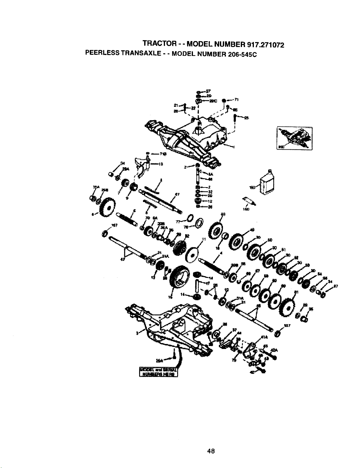
TRACTOR - - MODEL NUMBER 917.271072
PEERLESS TRANSAXLE - - MODEL NUMBER 206-545C
48
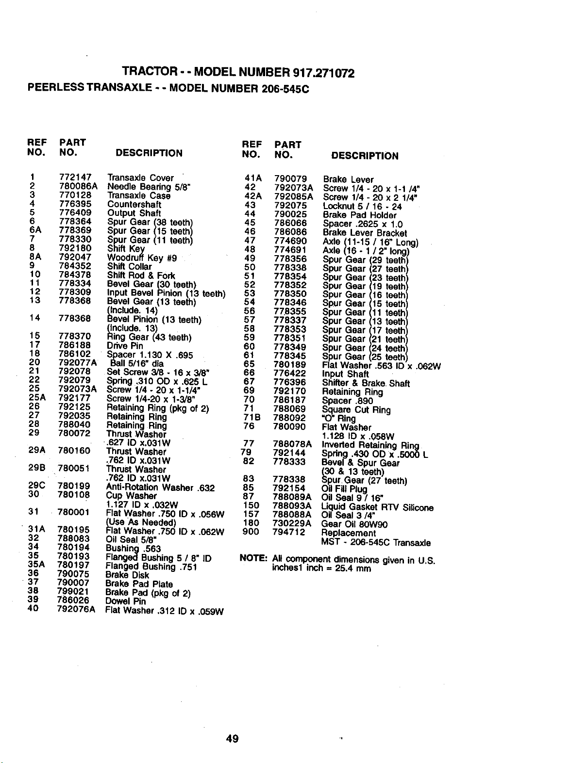
TRACTOR - - MODEL NUMBER 917.271072
PEERLESS TRANSAXLE - - MODEL NUMBER 206-545C
REF PART REF PART
NO. NO. DESCRIPTION NO. NO. DESCRIPTION
1 772147
2 780086A
3 770128
4 776395
5 776409
6 778364
6A 778369
7 778330
8 792180
8A 792047
9 784352
10 784378
11 778334
12 778309
13 778368
14 778368
15 778370
17 786188
18 786102
20 792077A
21 792078
22 792079
25 792073A
25A 792177
26 792125
27 792035
28 788040
29 780072
29A 780160
29B 780051
29C 780199
30 780108
31 780001
31A 780195
32 788083
34 780194
35 780193
35A 780197
36 790075
37 790007
38 799021
39 786026
40 792076A
TransaxlaCover
Needle Beedng 5/8"
Transaxla Case
Countershaft
Output Shaft
Spur Gear (38 teeth)
Spur Gear (15 teeth)
Spur Gear (11 teeth)
Shift Key
Woodruff Key #9
Shift Collar
Shift Rod& Fork
Bevel Gear (30 teeth)
Input Bevel Pinion (13 teeth)
Bevel Gear (13 teeth)
_nclude. 14)
evel Pinion (13 teeth
_nclude. 13)
ing Gear (43 teeth)
Drive Pin
Spacer 1,130 X .695
Ball 5/16" dia
Set Screw3/8 - 16 x 3/8"
_pdng ,310 OD x .625 L
crew 1/4 - 20 x 1-1/4"
Screw 1/4-20 x 1-3/8"
RetainingRing (pkg of 2)
Retaining Ring
Retaining Ring
Thrust Washer
,627 ID x.O31W
Thrust Washer
.762 ID x.031W
Thrust Washer
.762 ID x.031W
Anti-RotationWasher .632
Cup Washer
1.127 ID x .032W
Flat Washer .750 ID x .056W
tUse As Needed)
at Washer .750 ID x .062W
Oil Seal 5/8"
Bushing .563
Flanged Bushing5 / 8 ID
Flanged Bushing .751
Brake Disk
Brake Pad Plate
Brake Pad (pkg of 2)
Dowel Pin
Flat Washer ,312 ID x .059W
41A 790079
42 792073A
42A 792085A
43 792075
44 790025
45 786066
46 786086
47 774690
48 774691
49 778356
50 778338
51 778354
52 778352
53 778350
54 778346
56 778355
57 778337
58 778353
59 778351
60 778349
61 778345
65 780189
66 776422
67 776396
69 792170
70 786187
71 788069
71B 788092
76 780090
Brake Lever
Screw 1/4 - 20 x 1-1 /4"
Screw 1/4 - 20 x 2 114"
Locknut5 / 16 - 24
Brake Pad Holder
Spacer .2625 x 1.0
Brake Lever Bracket
Axle (11-15 / 16" Long)
Axla (16 - 1 / 2" long
Spur Gear, 29 teeth
Spur Gear, 27 teethl
)ur Gear, 23 teeth
_ur Gear 19 teeth
_ur Gear 16 teeth
_ur Gear 15 teeth
_ur Gear 11 teeth
_ur Gear 13 teeth
_ur Gear 17 teeth
_ur Gear 21 teeth
Spur Gear 24 teeth
Spur Gear 25 teeth
Flat Washer .563 ID .062W
Input Shaft
Shifter & Brake Shah
Retaining Ring
Spacer ,890
Square Cut Ring
"O"Ring
Flat Washer
1.128 ID x .058W
77 788078A inverted Retaining Ring
79 792144 Spdng .430 OD x .5000 L
82 778333 Bevel& Spur Gear
(30 & 13 teeth)
83 778338 Spur Gear (27 teeth)
85 792154 Oil Fill Plug .
87 788089A Oil Seal 9 / 16
150 788093A Liquid Gasket RTV Silicone
157 788088A Oil Seal 3/4"
180 730229A Gear Oil 80W90
900 794712 Replacement
MST - 206-545C Transaxla
NOTE:
All componentdimensionsgiven in U.S.
inches1inch= 25.4 mm
49
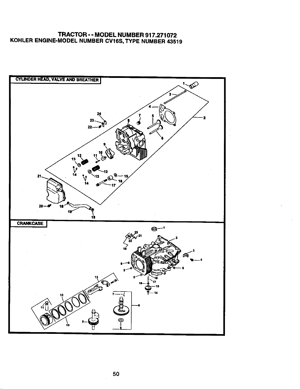
TRACTOR -- MODEL NUMBER 917.271072
KOHLERENGINE-MODELNUMBERCV16S,TYPENUMBER43519
CYLINDER HEAD, VALVE AND BREATHER I
7
/
\6
12
t0
13
5O
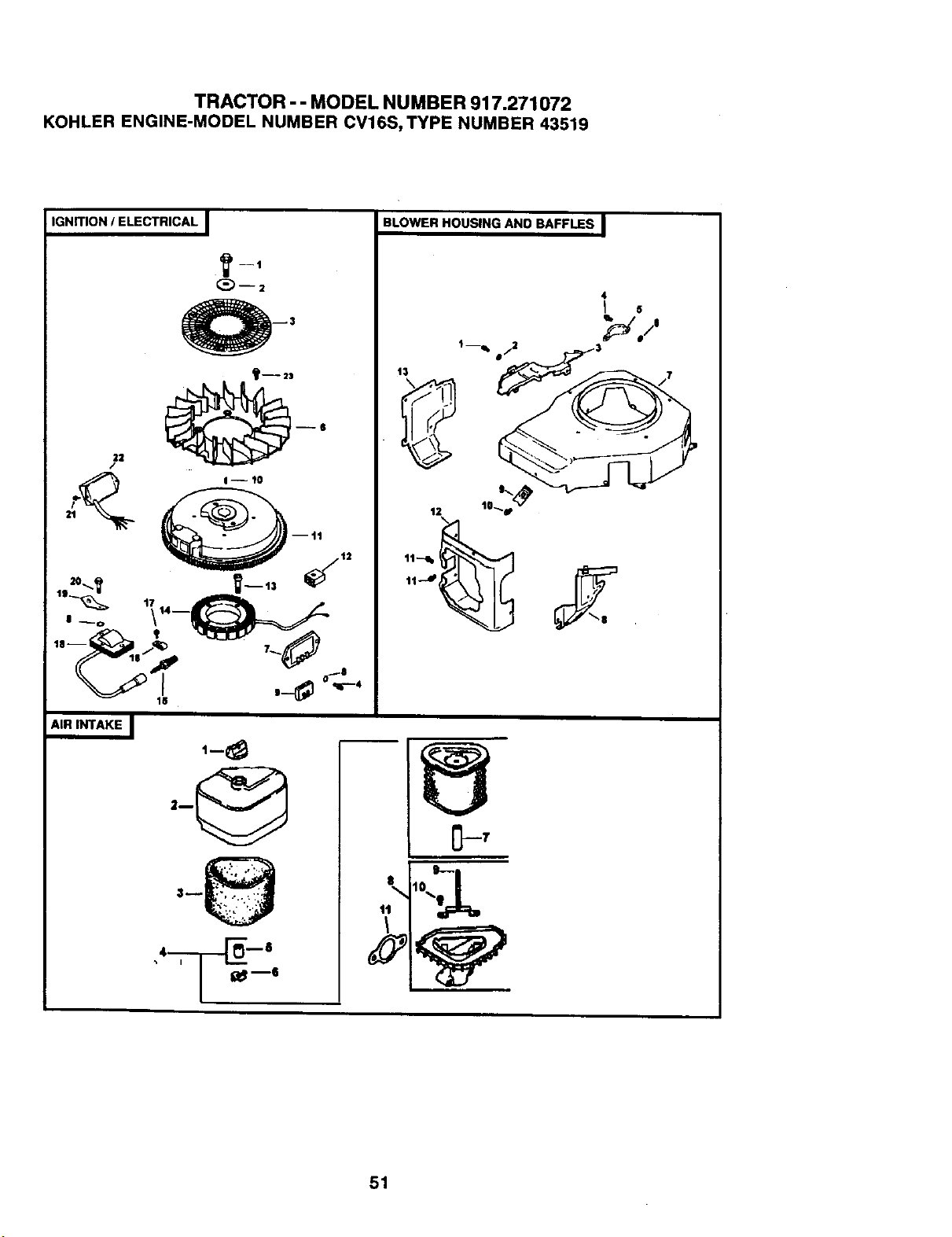
TRACTOR - - MODEL NUMBER 917.271072
KOHLER ENGINE-MODEL NUMBER CV16S, TYPE NUMBER 43519
IGNITION / ELECTRICAL I
22
/
II-- 10
I__o \ _
AIR INTAKE I
,-8
BLOWER HOUSING AND BAFFLES I
s I
\
fL_l"
4
_o_
lo
t0....
51
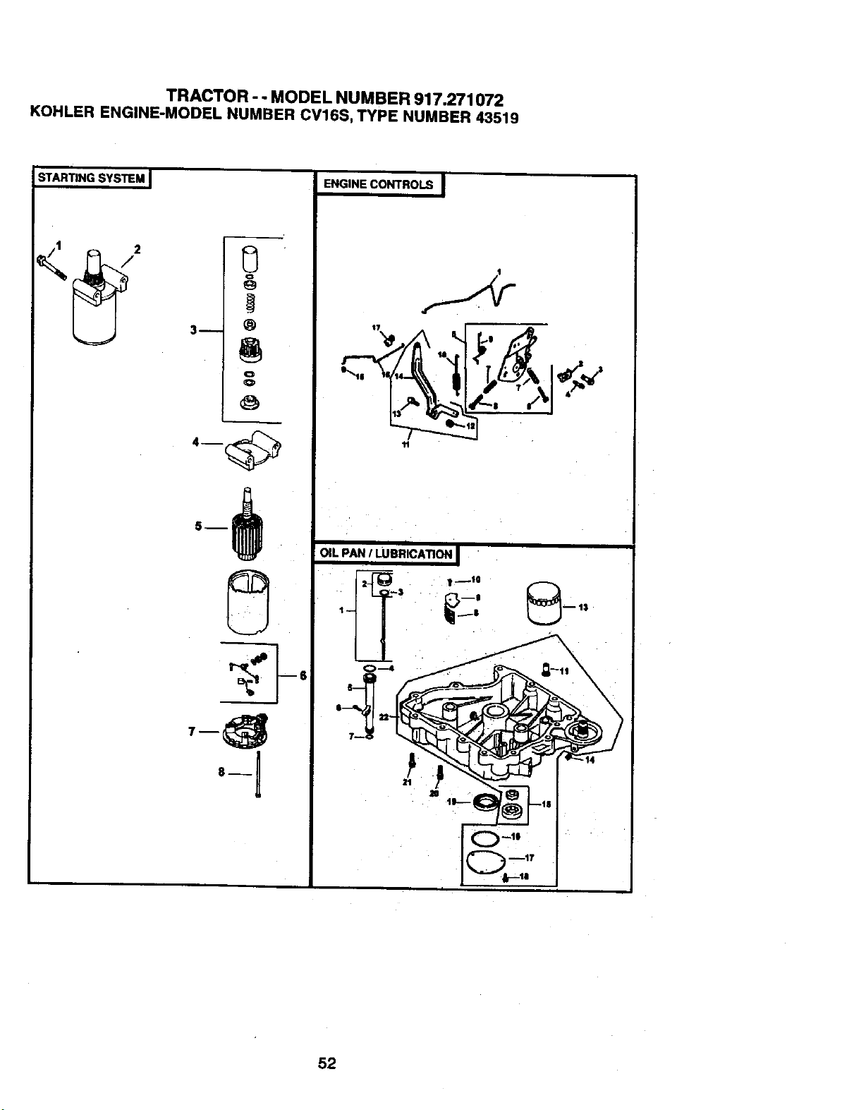
TRACTOR - - MODEL NUMBER 917,271072
KOHLER ENGINE-MODEL NUMBER CV16S, TYPE NUMBER 43519
STARTINGSYSTEM J
o
0
°1-1
8--
ENGINE CONTROLS
",_ _. ,
'11
I
OIL PAN / LUBRICATIONI
= _1 .. __$
tl
i
52
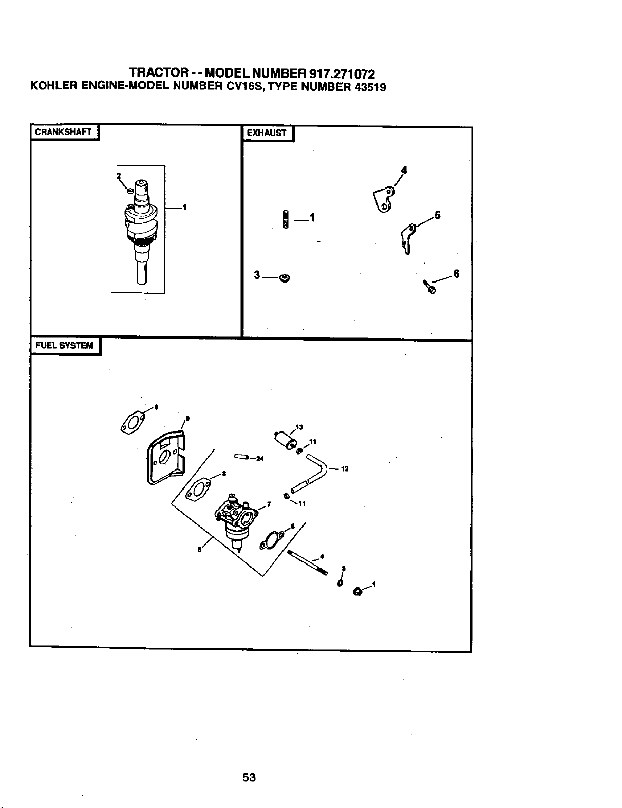
TRACTOR - - MODEL NUMBER 917.271072
KOHLER ENG|NE-MODEL NUMBER CV16S, TYPE NUMBER 43519
CRANKSHAFT J
ml
FUEL SYSTEM I
53
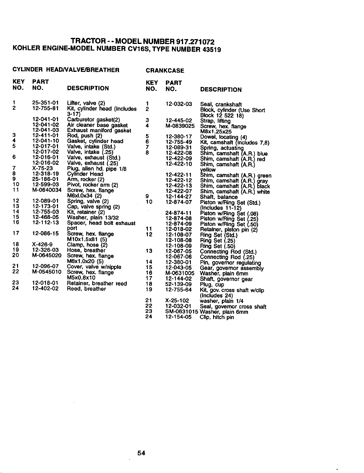
TRACTOR - - MODEL NUMBER 917.271072
KOHLER ENGINE-MODEL NUMBER CV16S, TYPE NUMBER 43519
CYLtNDER HEADNALVE/BREATHER
CRANKCASE
KEY PART KEY PART
NO. NO. DESCRIPTION NO. NO. DESCRIPTION
3
4
5
6
7
8
9
10
11
12
13
14
15
16
17
18
19
20
21
22
25-351-01 Lifter valve (2) 1 12-032-03 Seal, crankshaft
12-755-81 Kit, cylinder heed (Inc udes 2 Block, cylinder (Use Short
3-17)-
Block12 522 18)
12-041-01 Carburetor gasket(2) 3 12-445-02 Strap, lifting
12-041-02 Air cleaner base gasket 4 M-0839025 Screw, hex. flange
12-041-03 Exhaust maniford gasket M8xl.25x25
12-411-01 Rod, push (2) 5 12-380-17 Dowel, locating (4)
12-041-10 Gasket, cylinder head 6 12-755-49 Kit, camshaft (Inc|udes 7,8)
12-017-01 Valve, intake (Std.) 7 12-089-31 Spring, actuating
12-017-02 Valve, intake (.25) 8 12-422-08 Shim, camshaft (A.R.) blue
12-016-01 Valve, exhaust (Std.) 12-422-09 Shim, camshaft (A.R.) red
12-016-02 Valve, exhaust (.25) 12-422-10 Shim, camshaft (A.R.)
X-75-23 Plu_, allen hd. pipe 1/8 _e.lllow
12-318-19 Cyhnder Head 12-422-11 5him, camshaft (A.R.) green
25-186-01 Arm, rocker (2) 12-422-12 Shim, camshaft (A.R.) gray
12-599-03 Pivot, rocker arm (2) 12-422-13 Shim camshaft (A.R.) black
M-0640034 Screw, hax. flange 12-422-07 Shim, camshaft (A.R.) wh te
M6xt.0x34 (2) 9 12-144-27 Shaft, balaP,ce
Piston w/Ring Set (Std.)
12-089-01 Spring, valve (2) 10 12-874-07 (Includes 11-12)
12-173-01 Cap, valve spring (2)
12-755-03 Kit, retainer (2) 24-874-11 Piston w/Ring Set (.08)
12-468-05 Washer, plain 13/32 12-874-08 Piston w/Ring Set (.25)
12-112-13 Spacer, head bolt exhaust 12-874-09 PLston w/Ring Set (.50)
port 11 12-018-02 Retainer, piston pin (2)
12-086-15 Screw, hex. flange 12 12-108-07 Ring Set (Std.)
M10x1.5x81 (5) 12-108-08 Ring Set (.25)
X-426-9 Clamp, hose (2) 12-108-09 Ring Set (.50)
12-326-O3 Hose, breather 13 12-067-05 Connecting Rod (Std.)
M-0645020 Screw, hex. flange 12-067-06 Connecting Rod (.25)
M6xl,0x20 (5) 14 12-380-01 Pin, governor regulating
12-096-07 Cover, valve w/nipple 15 12-043-05 Gear, govemor assembly
M-0545010 Screw, hex. flange 16 M-0631005 Washer, plain 6ram
M5xO.8xl0 17 12-144-02 Shaft, governor gear
12-018-01 Retainer, breather reed 18 52-139-09 Plug, cup
12-402-02 Reed, breather 19 12o755-64 Kit, gov. cross shaft w/clip
(Includes 24)
21 X-25-102 washer, plain 1/4
22 12-032-01 Seal, governor cross shaft
23 SM-0631015 Washer, plain 6ram
24 12-154-05 Clip, hitch pin
23
24
54
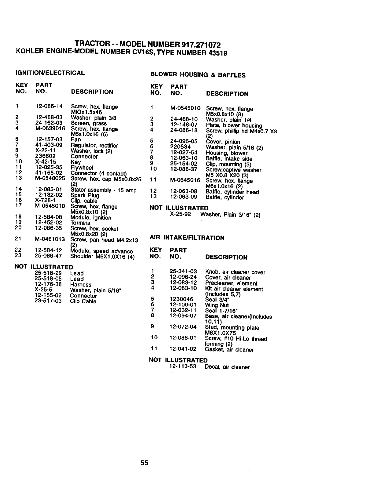
TRACTOR -- MODEL NUMBER 917.271072
KOHLER ENGINE-MODEL NUMBER CV16S, TYPE NUMBER 43519
IGNITION/ELECTRICAL BLOWER HOUSING & BAFFLES
KEY PART KEY PART
NO. NO. DESCRIPTION NO, NO. DESCRIPTION
1 12-066-14 Screw, hex. flange
MIOX1.5x46
2 12-468-03 Washer, plain 3/8
3 24-162-03 Screen, grass
4 M-0639016 Screw, hex. flange
M6x1.0x16 (6)
6 12-157-03 Fan
7 41-403-09 Regulator, rectifier
6 X-22-11 Washer, lock (2)
9 236602 Connector
10 X-42-15 Key
t 1 12-025-35 Flywheel
12 41ol 55-02 Connector (4 contact)
13 M-0548025 Screw, hex. cap M5x0.8x25
(;2)
14 12-085-01 Stator assembly - 15 amp
15 12-132-02 Spark Plug
16 X-728-1 Clip, cable
17 M-0545010 Screw, hex. flange
MSx0.8xl0 (2)
18 12-584-08 Module, ignition
19 12-452-02 Terminal
20 12-086-35 Screw, hex. socket
M5x0.6x20 (2)
21 M-0461013 Screw, panhead M4.2x13
(2)
22 12-584-12 Module, speed advance
23 25-066-47 Shoulder M6X1.0X16 (4)
NOT ILLUSTRATED
25-518-29 Lead
25-518-05 Lead
12-176-36 Harness
X-25-5 Washer, plain 5/16"
12-155.02 Connector
23-517-03 Clip Cable
2
3
4
5
6
7
8
9
t0
11
12
13
M-0545010
24-468-10
12-146-07
24-086-18
24-096-05
220534
12-027-54
12-063-10
25-154-02
t 2-086-37
M-0645016
12-063-08
12-063-09
Screw, hex. flange
MSx0.8xl0 (5)
Washer, plain 1/4
Plate, blower housing
Screw, phillip hd M4x0.7 X8
(2)
Cover, pinion
Washer, plain 5/16 (2)
Housing, blower
Baffle, intake side
Clip, mounting (3)
Screw,captive washer
M5 X0.8 X20 (3)
Screw, hex. flange
M6xl.Ox16 (2)
Baffle, cylinder head
Baffle, cylinder
NOT ILLUSTRATED
X-25-92 Washer, Plain 3/16_ (2)
AIR INTAKE/FILTRATION
KEY PART
NO. NO. DESCRIPTION
Knob,air cleaner cover
Cover, air cleaner
Precleaner, element
Kit air cleaner elemenl
_ncludes 5,7)
eal 3/4"
Wing Nut
Seal 1-7/16"
Base, air cleaner(Includes
10,11)
Stud, mountingplate
M6X1.0X75
Screw, #10 Hi-Lo thread
forming(2)
Gasket, air cleaner
1 25-341-03
2 12-096-24
3 12-083-12
4 12-083-10
5 1230046
6 12-100-01
7 12-032-11
8 12-094-07
9 12-072-04
10 12-086-01
11 12-041-02
NOT ILLUSTRATED
12-113-53 Decal, air cleaner
55
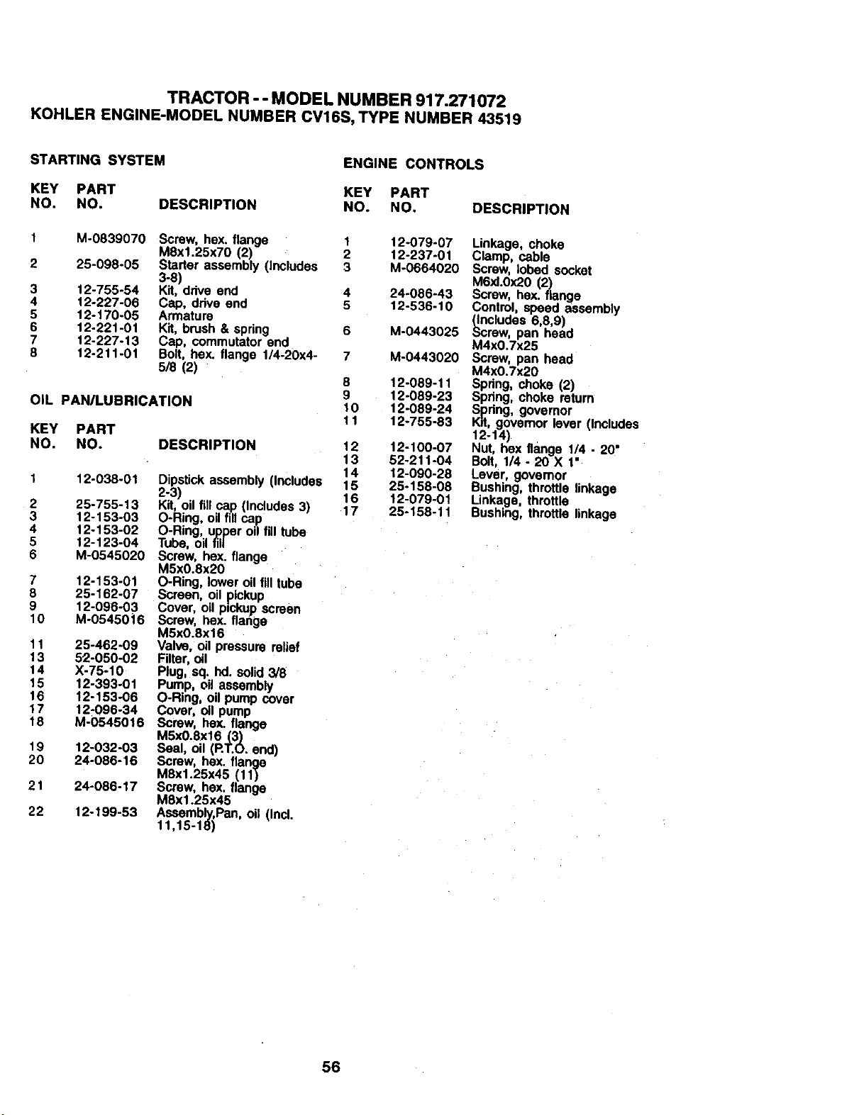
TRACTOR -- MODEL NUMBER917.271072
KOHLERENGINE-MODELNUMBERCV16S,TYPENUMBER43519
STARTING SYSTEM ENGINE CONTROLS
KEY PART KEY PART
NO. NO. DESCRIPTION NO. NO. DESCRIPTION
3
4
5
6
7
8
M-0839070 Screw, hex. flange 1
M8x1.25x70 (2) 2
25-098-05 Starter assembly (Includes 3
3-8)
12-755-54 Kit, drive end 4
12-227-06 Cap, drive end 5
12-170-05 Armature
12-221-01 Kit, brush & spring 6
12-227-13 Cap, commutator end
12-211-01 Bolt, hex. flange 1/4-20x4- 7
5/8 (2)
OIL PAN/LUBRICATION
KEY PART
NO. NO. DESCRIPTION
1 12-038-01
2 25-755-13
3 12-153-03
4 12-153-02
5 12-123-04
6 M-0545020
7 12-153-01
8 25-162-07
9 12-096-03
10 M-05450i6
11 25-462-09
13 52-050-02
14 X-75-10
15 12-393-01
16 12-153-06
17 12-096-34
18 M-0545016
19 12-032-03
20 24-086-16
21 24-086-17
22 12-199-53
Dipst'mkassembly (Includes
2-3)
Kit,oilfillcap.(Includes3)
O-Ring,oilfillcap
O-Ring, upper oilfill tube
Tube, oilfill
Screw, bex flange
M5xO.8x20
O-Ring, loweroilfill tube
Screen, oil pickup
Cover, oilp=ckupscman
Screw, hex. flange
M5xO.8x16
Valve, oil pressure relief
Filter,oil
Plug, sq. hd.solid3/8
Pump, oil assembly
O-Ring, oil pumpcover
Cover, oil pump
Screw, hex. flange
M5x0.8x16 (3)
Seal, oil (RT.O. end)
Screw, hex. flange
M8x1.25x45 (11)
Screw, hex. flange
M8x1.25x45
Assembly,Pan, oil (Incl.
11,15-18)
8
9
10
11
12
13
14
15
16
17
12-079-07
12-237-01
M-0664020
24-086-43
12-536-10
M-0443025
M-0443020
12-089-11
12-089-23
12-089-24
12-755-83
12-100-07
52-211-04
12-090-28
25-158-08
12-079-01
25-158-11
Linkage, choke
Clamp, cable
Screw, lobed socket
M6xl.Ox20(2)
Screw, hex. flange
Control,speed assembly
_cludes 6,8,9)
rew, pan bead
M4x0.7x25
Screw, pan bead
M4x0.7x20
Spring,choke (2)
Spr_ng,choke return
Spring, governor
Kit,governor lever (Includes
12-14)
Nut, bex flange 1/4 - 20
Bolt, 1/4 - 20 X 1"
Lever, governor
Bushing,throttle linkage
Linkage, throttle
Bushing,throttle linkage
56
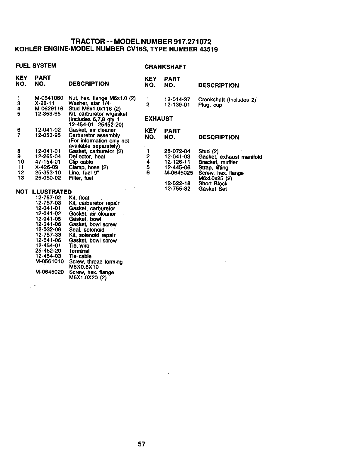
TRACTOR -- MODEL NUMBER 917.271072
KOHLER ENGINE-MODEL NUMBER CV16S, TYPE NUMBER 43519
FUEL SYSTEM
CRANKSHAFT
KEY PART KEY PART
NO. NO. DESCRIPTION NO. NO. DESCRIPTION
1 M-0641060 Nut, hex. flange M6xl.0 (2) 1 12-014-37 Crankshaft (Includes 2)
3 X-22-11 Washer, star 1/4 2 12-139-01 Plug, cup
4 M-0629116 Stud M6x1.0x116 (2)
5 12-853-95 Kit, carburetor w/gasket
(includes 6,7,8 qty 1 EXHAUST
12-454-01, 25452-20)
6 12-041-02 Gasket, air cleaner KEY PART
7 12-053-95 Carburetor assembly NO. NO. DESCRIPTION
(For information only not
available separately)
8 12-041-01 Gasket, carburetor (2) 1 25-072-04 Stud (2)
9 12-265-04 Deflector, heat 2 12-041-03 Gasket, exhaust manifold
10 47-154-01 Clip cable 4 12-126-11 Bracket, muffler
11 X-426-09 Clamp, hose (2) 5 12-445-06 Strap, tiffing
12 25-353-10 Line, fuel 9" 6 M-0645025 Screw, hsx. flange
13 25-050-02 Filter, fuel M6xl.0x25 (2)
12-522-18 Short Block
NOT ILLUSTRATED 12-755-82 Gasket Set
12-757-02 Kit, float
12-757-03 Kit, carburetor repair
12-041-01 Gasket, carburetor
12-041-02 Gasket, air cleaner
12-041-05 Gasket, bowl
12-041-06 Gasket, bowl screw
12-032-06 Seal, solenoid
12-757-33 Kit, solenoid repair
12-041-06 Gasket, bowl screw
12-454-01 Tie, wire
25-452-20 Terminal
12-454-03 Tie cable
M-0561010 Screw, thread forming
M5XO.8XIO
M-0645020 Screw, hex. flange
M6X1.0X20 (2)
57

58

SUGGESTED GUIDE FOR SIGHTING SLOPES FOR SAFE OPERATION
I SIGHTING
GUIDE
ONLY RIDE UP AND DOWN HILL,
NOT ACROSS HILL
O1
(D
I d_) Operate your Tractor up and down the face of slopes (not I
I
greater than 15°), never across the face. Make turns gradu-
I
ally to prevent tipping or loss of control. Exercise extreme
caution when changing direction on slopes.

For in-home major brand repair service:
Call 24 hours a day, 7 days a week
1-800-4-MY-HOME sM (1-800-469-4663)
Para pedir servicio de reparaci6n a domicilio
1-800-676-5811
In Canada for all your service and parts needs call
Au Canada pour tout le service ou les pi_ces
1-800-885-4455
For the repair or replacement parts you need:
Call 6 am - 11 pm CST, 7 days a week
PartsDirects-
1-800-366-PART (1-800-366-7278)
Para ordenar piezas con entrega a domicilio
1-800-659-7084
For the location of a Sears Parts and Repair Center
in your area:
Call 24 hours a day, 7 days a week
1-800-488-1222
For information on purchasing a Sears Maintenance
Agreement or to inquire about an existing Agreement:
Call 9 am - 5 pm, Monday - Saturday
1-800-827-6655
SEARS
Home Central"
173622 12.13.99 RD Printed in U.S.A.


