Loading ...
Loading ...
Loading ...
7
REV 1 - 1108241145
L-C2-329
*Note: If using an insulating liner, consult liner instructions for counter cut-out
dimensions and installation.
MODEL SPECIFICATIONS
Fire-Magic
®
Model Specifi cations Table
Table 1 E660i E790i E1060i
Countertop to unit bottom (cut-out)* 12" 12" 12"
Side to side (noncombustible cut-out)* 31-
1
/
4
" 37" 50"
Front to back (noncombustible cut-out)* 23-
1
/
2
" 23-
1
/
2
" 23-
1
/
2
"
Control panel width 32-
3
/
4
" 38-
1
/
2
" 51-
1
/
2
"
Main burner BTU
N/P orifi ce drill size
25,000
#42/#54
32,000
#38/#53
28,000
#40/#53
Backburner BTU
N/P orifi ce drill size
19,000
#49/#57
23,000
#44/#56
15,000
#51/#58
Smoker drawer burner BTU
N/P orifi ce drill size
2,500
#68/#77
2,500
#68/#77
2,500
#68/#77
Infrared searing burner BTU
N/P orifi ce drill size
24,000
#45/#55
24,000
#45/#55
24,000
#45/#55
Optional Echelon insulating liner model # 3176-50 3186-50 3185-50
Oven Lights Rating 12V / 10 watt halogen light bulb
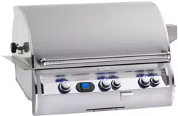
TOP VIEW
Control panel width
Countertop
Lower support
Countertop overhang
Front to back
11"
10"
1-1
/
4
"
Extra cut-out for
Power Hood only!
2
3
/
4
"
Control
Panel
NON-COMBUSTIBLE
CABINET CUT-OUT
DIMENSIONS
Fig. 7-1
Side to side
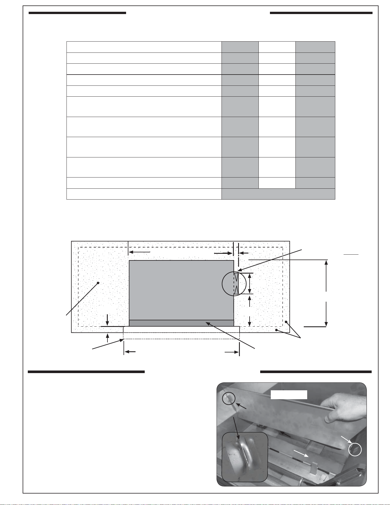
INSTALL ZONE DIVIDERS
Fig. 7-1
Zone divider
Groove
Groove
Front
Place the zone dividers as shown (Fig. 7-1) into
the grooves in the inner fi rewall of the grill to
allow for maximum heat control and thermometer
accuracy in each zone. Remove and store during
rotisserie use.
Loading ...
Loading ...
Loading ...