Loading ...
Loading ...
Loading ...
Flex + Series
13
NO. ① ② ③ ④
Name Coping plate Rear side plate Front side plate Gas side stop valve
NO. ⑤ ⑥ ⑦
Name Liquid side stop valve Right connection board Front connection board
NO. A B C D
Name Front connection Bottom connection Side connection Rear connection
Fig. 15
1) Unscrew the coping plate, front side plate, right connection board and front connection board.
2) The refrigerant pipes can be installed in four directions, please choose the proper direction.
3) Knock the holes in the plate of the chosen direction with the drill and hammer.
4) Connect the pipes to the stop valves.
5) Bend the pipes to go through the knockout holes.
6) Cover the through-holes with sealing materials to prevent the water, dust or small animals going
into the outdoor unit.
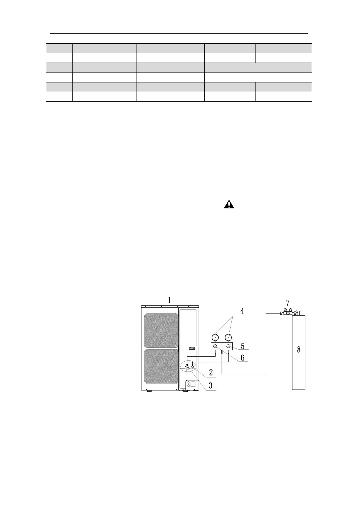
6.6 Leak Test
1) Please make sure that the stop valves of the outdoor unit are closed during the operation.
2) The leak test should be made by pressurizing nitrogen gas.
WARNING! Do not mix
oxygen, C
2
H
2
or other dangerous gas into the refrigerant circuit.
3) Turn on the Hi-knob and Lo-knob.
NOTICE! The leak test should be done simultaneously
at both the gas and liquid stop valves.
4) Open the pressure reducing valve, pressurize the connection pipes to 1.0 MPa (10 bar) slowly,
wait fifteen minutes, and make sure that the pressure will not drop.
5) Rise the pressure to 4.0 MPa (40 bar) slowly, wait 24 hours and make sure the pressure will not
drop
6) If the pressure does not decrease, the pipes have passed the test. Otherwise, look for where the
gas leaks from.
1: Outdoor unit
2: Liquid side stop valve
3: Gas side stop valve
4: Pressure-vacuum gauge
5: Hi-knob
6: Lo-knob
7: Pressure reducing valve
8: Nitrogen
Fig. 16
6.7 Vacuum Operation
1) Make sure the stop valves of the outdoor unit are closed fully during the operation.
2) As shown in the following figure, expel the gas from the refrigerant pipes by the vacuum pump.
3) Open the pump and turn on the knobs to evacuate the gas in the liquid and gas pipes.
NOTICE!
The vacuuming should be done simultaneously at both the gas and liquid stop valves.
4) When the pressure of the system is less than -0.1Mpa (-1bar), keep the system for more than
Loading ...
Loading ...
Loading ...