Loading ...
Loading ...
Loading ...
Usea middleor lowerpositionwhentheareato be clearedis
uneven,such as a graveldriveway.
NOTE:Ifyou chooseto operatethe snowthroweron a gravelsurface,
keepthe skid shoesin positionfor maximumclearancebetweenthe
groundandthe shaveplate.
Operatinga snowthrowerequippedwith steelskidshoesmayresult
indamageto naturalstonepaversurfaces(e.g.sandstone,blue-
stone,limestone). Forinformationonavailablepolymerskidshoes,
call 1-800-4MY-HOME.
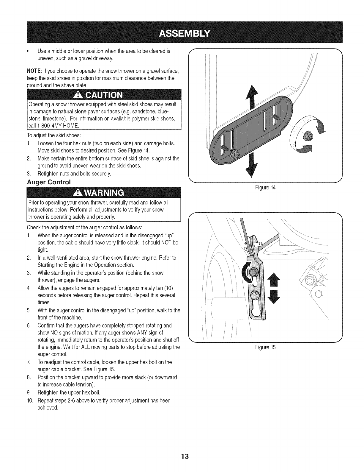
Toadjustthe skidshoes:
1. Loosenthe fourhex nuts(twooneach side)and carriagebolts.
Moveskidshoesto desiredposition.See Figure14.
2. Makecertain theentirebottomsurfaceof skid shoeis againstthe
groundto avoidunevenwearon the skidshoes.
3. Retightennutsandboltssecurely.
Auger Control
Priorto operatingyoursnowthrower,carefullyreadand followall
instructionsbelow.Performalladjustmentsto verifyyour snow
throweris operatingsafelyand properly.
Checktheadjustmentof the augercontrolas follows:
1. Whentheaugercontrolis releasedand in the disengaged"up"
position,the cableshouldhavevery littleslack.ItshouldNOTbe
tight.
2. In a well-ventilatedarea,start the snowthrowerengine.Referto
Startingthe Engineinthe Operationsection.
3. Whilestandingin the operator'sposition(behindthe snow
thrower),engagethe augers.
4. Allowtheaugersto remainengagedfor approximatelyten (10)
secondsbeforereleasingthe augercontrol.Repeatthisseveral
times.
5. With theauger controlin thedisengaged"up" position,walkto the
frontof the machine.
6. Confirmthatthe augershavecompletelystoppedrotatingand
showNOsignsof motion.If anyaugershowsANY signof
rotating,immediatelyreturnto the operator'spositionand shutoff
the engine.Waitfor ALLmovingpartsto stop beforeadjustingthe
augercontrol.
7. Toreadjustthecontrolcable, loosentheupperhexbolt on the
augercablebracket.SeeFigure15.
8. Positionthe bracketupwardto providemoreslack(or downward
to increasecabletension).
9. Retightenthe upperhex bolt.
10. Repeatsteps2-6 aboveto verifyproperadjustmenthasbeen
achieved.
Figure14
J
f
Figure15
f
/
J
13
Loading ...
Loading ...
Loading ...