Loading ...
Loading ...
Loading ...
INSTALLATION INSTRUCTIONS
DIMENSIONS AND CLEARANCES
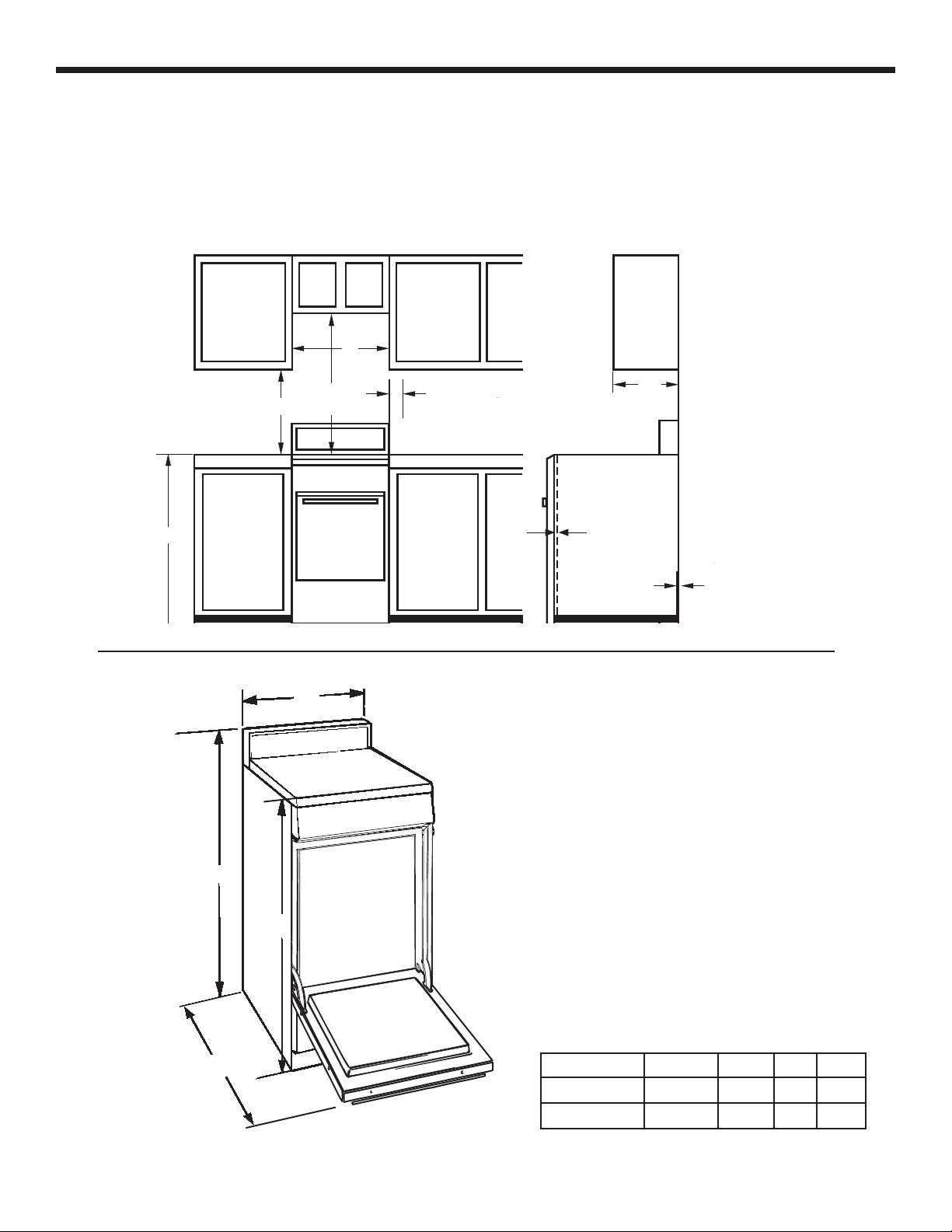
Provide adequate clearances between the range and adjacent combustible surfaces. These dimensions must be met for
safe use of your range. The placement of the power outlet and the opening of the piping (refer to Locations of Gas and
Electric) can be adjusted to comply with the specifi c requirements.
The range may be placed with 0” clearance below cooktop and at the back wall.
0RGHOV $ % & '
:LGH
øµ
:LGH
øµ
$
øµ
'
0D[LPXPGHSWK
IRUFDELQHWVDERYH
FRXQWHUWRSV
0LQLPXPWR
FDELQHWVRQ
HLWKHUVLGH
RIUDQJH
0LQLPXP
%
&
0LQLPXPWRZDOORQ
HLWKHUVLGHRIUDQJH
DERYHKHLJKW
7RFDELQHWVEHORZ
FRRNWRSDQGDWWKH
UDQJHEDFN
)URQWHGJHRI
WKHUDQJHVLGH
SDQHOIRUZDUG
IURPWKH
FDELQHW
To cabinets below
cooktop and at the
range back
Maximum depth
for cabinets above
countertops
Minimum to
cabinets on
either side
of range
Minimum to wall on
either side of range
above 36” height
Front edge of
the range side
panel forward
from the
cabinet
Minimum
24
Models A B C D
20” wide 20” 20 ⅜” 2” 41”
24” wide 24” 24 ⅜” 2” 41”
Loading ...
Loading ...
Loading ...