www.outdoorrooms.com
!
!
!
!
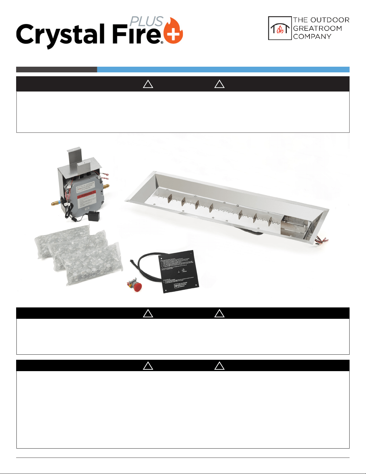
The information in this instruction manual is intended only as a supplement to the Crystal Fire Plus®
instruction manual and is not an exhaustive installation manual. If the information in both instruction
manuals is not followed exactly, a re or explosion may result causing property damage, personal,
injury or loss of life.
WARNING
Supplemental Commercial Installation Instructions
User Manual for Commercial Burner Installations and Burner Plates
!!
WARNING
WARNING
FOR OUTDOOR USE ONLY.
Installation and service must be performed by a qualied installer, service agency,
or the gas supplier.
The Outdoor GreatRoom Company
TM
, LLC disclaims any responsibility for, and the warranty will be
voided by, the following actions:
• Installation and use of any damaged components
• Modication of the burner assembly or included components
• Installation other than detailed in this manual
Any such action may result in a re or explosion causing property damage, personal injury, or death.
2
www.outdoorrooms.com
42511 REV B : 03-16-2021
TABLE OF CONTENTS
1. Commercial Controls
a. Controls on Appliance
• 4HRTC - 4-Hour Timer Control Panel
b. Controls Away from Appliance
• CFP-ESO-CP - Emergency Stop
• WSES-CP - ON/OFF Wall Switch and Emergency Stop
• 4HRTES-CP - 4-Hour Timer and Emergency Stop
C. Additional Information
• CF-DSI-SB - Switch Bypass
2. Burner Plate Information
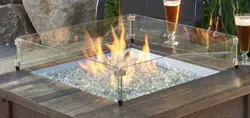
a. Square Burner Plates
b. Round Burner Plates
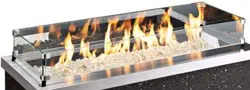
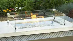
c. Linear Burner Plates
3
3
5
11
13
13
15
17

3
www.outdoorrooms.com
42511 REV B : 03-16-2021
A. CONTROLS ON APPLIANCE
INSTALLATION DIAGRAM - (4HRTC)
Control panel secured to appliance enclosure
1
COMMERCIAL CONTROLS
KEY
Low-Voltage
High-Voltage
Commercial Burner
Enclosure
4HRTC
4-HOUR TIMER CONTROL PANEL
GFCI receptacle with weatherproof cover
Installed on the appliance.
Includes 36 in. wire lead that connects directly
to CF-DSI.
Replaces the standard CF-DSI control switch.
Eliminates remote (CF-DSI-R) functionality.
Operates low-voltage circuit.
•
•
•
•
•
4
www.outdoorrooms.com
42511 REV B : 03-16-2021
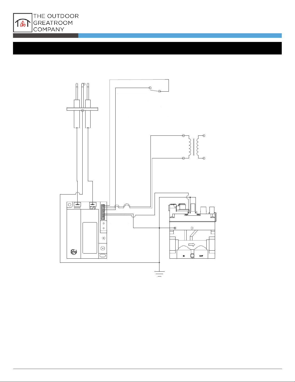
WIRING DIAGRAM - (4HRTC)
SENSOR/IGNITER
4HRTC
3.3 VDC+
3.3 VDC-
CONTROL
MODULE
GAS CONTROL
VALVE
SUPPLY FROM GFCI
RECEPTACLE
110-120VAC

5
www.outdoorrooms.com
42511 REV B : 03-16-2021
B. CONTROLS AWAY FROM APPLIANCE
CFP-ESO-CP
EMERGENCY STOP
KEY
Low-Voltage
High-Voltage
INSTALLATION DIAGRAM - (CFP-ESO-CP)
GFCI receptacle with weatherproof cover
CFP-ESO-CP on
wall OR pillar
Commercial Burner
Enclosure
Standard control panel
OR timer control panel on
appliance enclosure
•
•
•
•
•
Installed away from the appliance.
Install on a wall or pillar in accordance with local
electrical code.
Includes printed instruction cover plate.
Mounts to single-gang junction box.
Immediately cuts high-voltage to the appliance
circuit.

6
www.outdoorrooms.com
42511 REV B : 03-16-2021
WIRING DIAGRAM - (CFP-ESO-CP)
SENSOR/IGNITER
3.3 VDC+
3.3 VDC-
CONTROL
MODULE
GAS CONTROL
VALVE
STANDARD
CONTROL
SWITCH
ESO
(NORMALLY CLOSED)
!!
WARNING
If any components were damaged during the incident that prompted the use of the emergency stop
button, they must be replaced before the appliance is operated again. In some instances, the entire
appliance should be replaced.
After emergency stop is pressed and situation is resolved, DO NOT immediately reset the
emergency stop button. Follow these steps to reset:
Turn all controls to the OFF position. This includes the CF-DSI switch, the 4-hour
timer, and/or the wall switch.
Verify that appliance is not covered or obstructed.
Reset the emergency stop button by twisting clockwise.
1.
2.
3.
SUPPLY FROM GFCI
RECEPTACLE
110-120VAC
7
www.outdoorrooms.com
42511 REV B : 03-16-2021
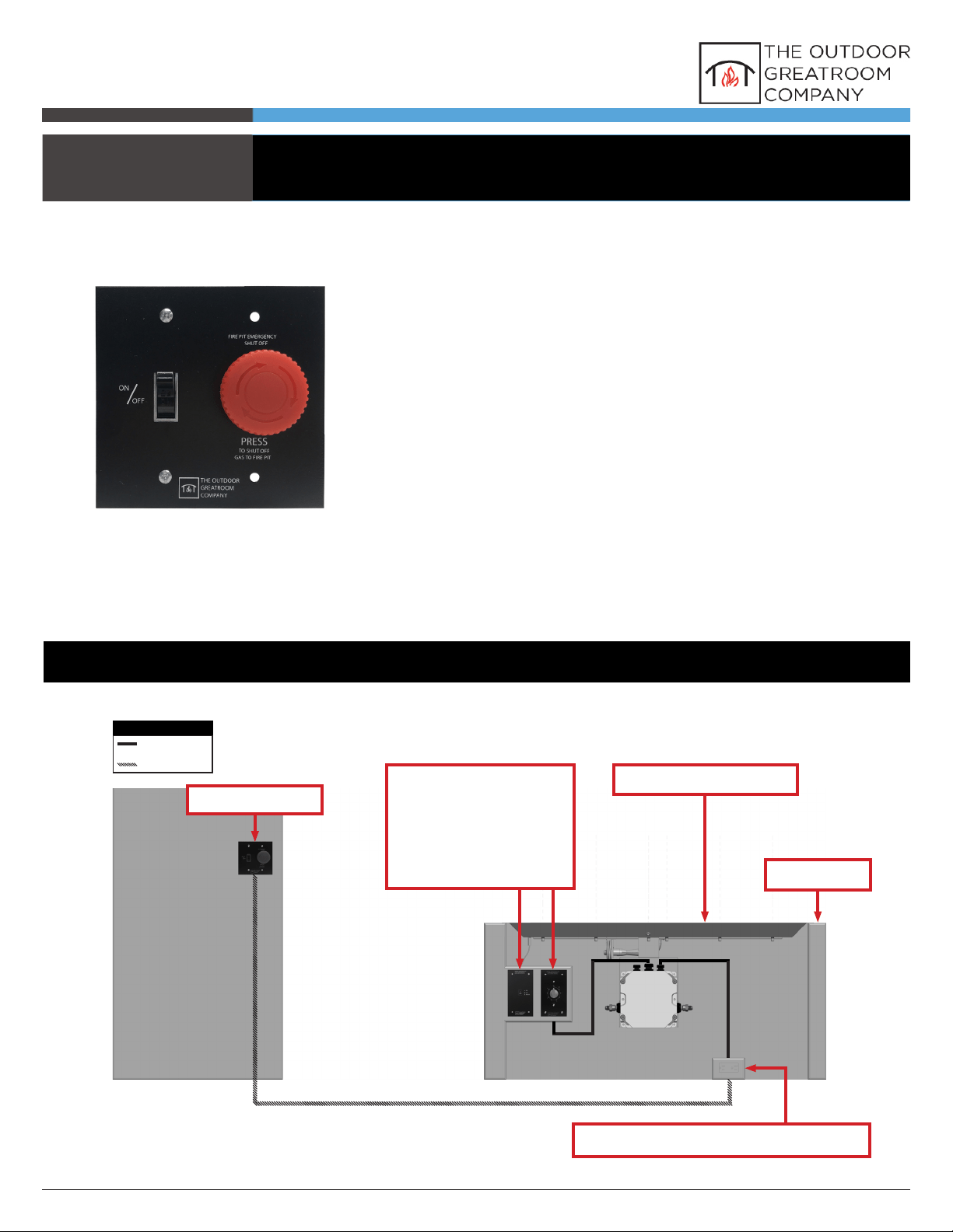
INSTALLATION DIAGRAM - (WSES-CP)
Installed away from the appliance.
Only install on a wall within line-of-sight of the
appliance in accordance with local electrical code.
Includes printed instruction cover plate.
Mounts to double-gang junction box
Operates high-voltage.
Included DSI switch bypass (CF-DSI-SB) can be
installed on DSI to remove control from appliance
and give sole control to the WSES-CP.
If CF-DSI-SB is installed, remote functionality is
removed.
WSES-CP on wall
Standard control panel
OR timer control panel on
appliance enclosure
Switch bypass eliminates
on appliance controls
GFCI receptacle with weatherproof cover
KEY
Low-Voltage
High-Voltage
Commercial Burner
Enclosure
WSES-CP
ON/OFF WALL SWITCH AND EMERGENCY STOP
•
•
•
•
•
•
•
8
www.outdoorrooms.com
42511 REV B : 03-16-2021
WIRING DIAGRAM - (CFP-ESO-CP)
CONTROL
MODULE
GAS CONTROL
VALVE
3.3 VDC+
3.3 VDC-
SENSOR/IGNITER
ESO
(NORMALLY CLOSED)
WALL SWITCH
(NORMALLY OPEN)
STANDARD
CONTROL
SWITCH
SUPPLY FROM GFCI
RECEPTACLE
110-120VAC
9
www.outdoorrooms.com
42511 REV B : 03-16-2021
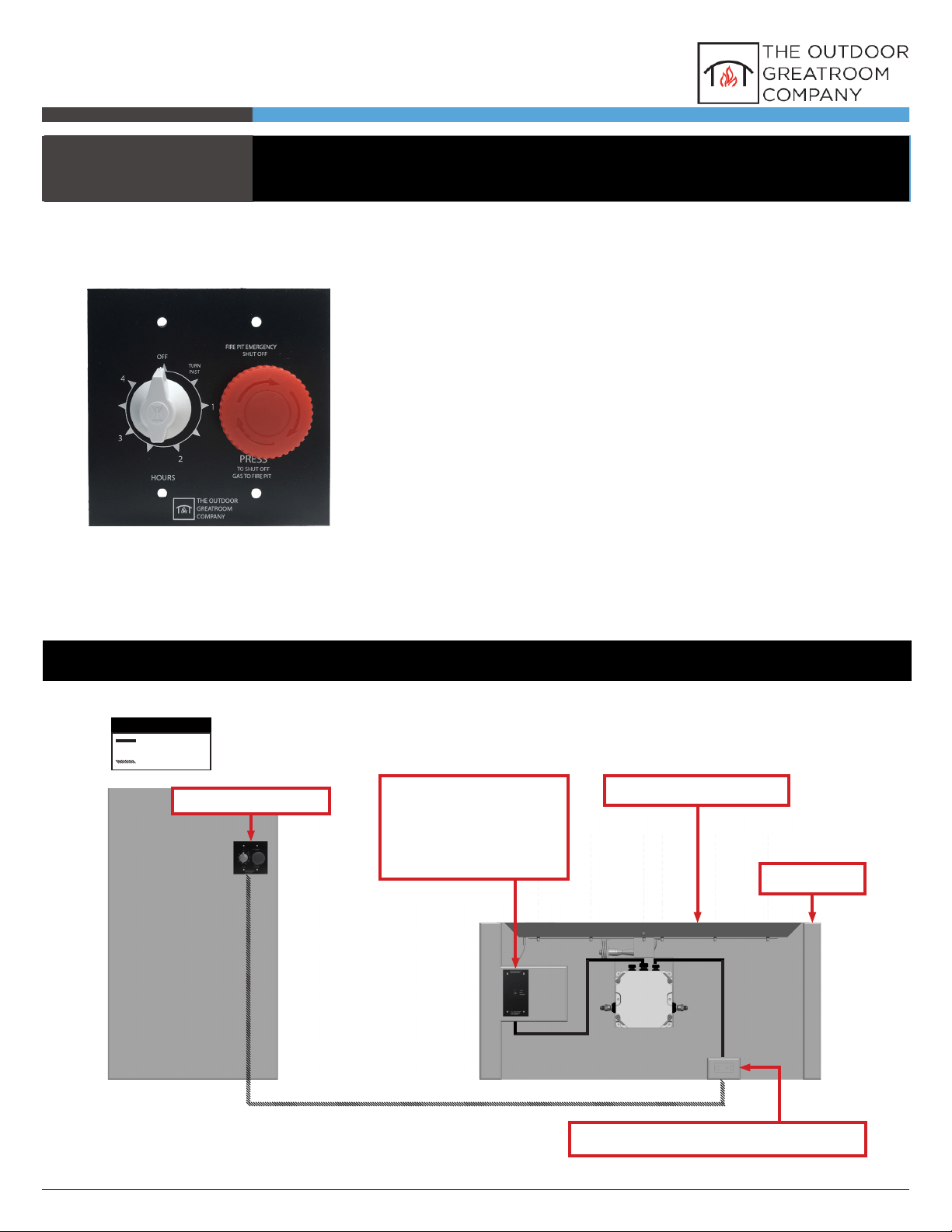
4HRTES-CP
4-HOUR TIMER AND EMERGENCY STOP
INSTALLATION DIAGRAM - (4HRTES-CP)
KEY
Low-Voltage
High-Voltage
4HRTES-CP on wall
GFCI receptacle with weatherproof cover
Enclosure
•
•
•
•
•
•
•
Installed away from the appliance.
Only install on a wall within line-of-sight of the
appliance in accordance with local electrical code.
Includes printed instruction cover plate.
Mounts to double-gang junction box
Operates high-voltage.
Included DSI switch bypass (CF-DSI-SB) can be
installed on DSI to remove control from appliance
and give sole control to the WSES-CP.
If CF-DSI-SB is installed, remote functionality is
removed.
Commercial Burner
Standard control panel on
appliance enclosure
Switch bypass eliminates
on appliance controls

10
www.outdoorrooms.com
42511 REV B : 03-16-2021
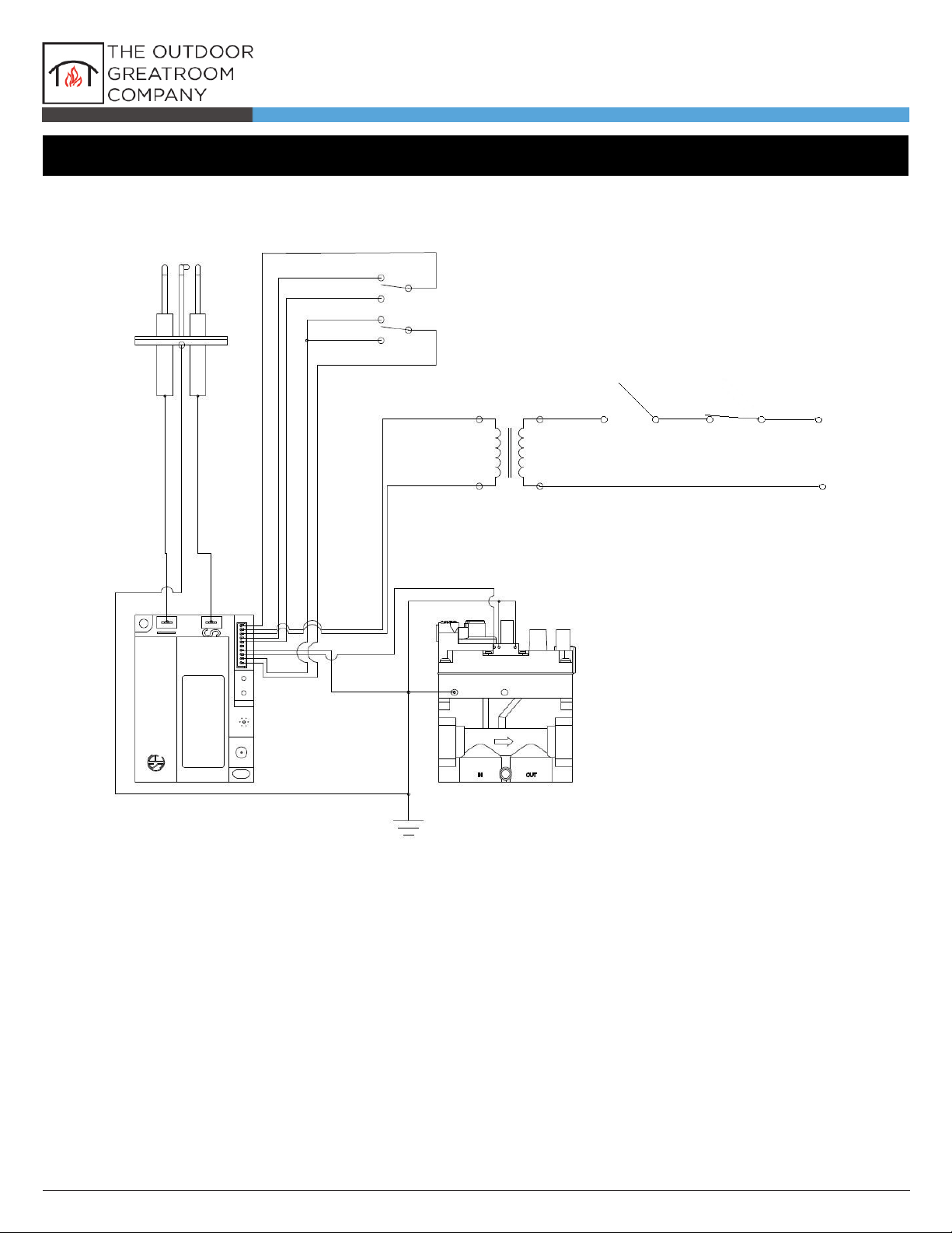
CONTROL
MODULE
GAS CONTROL
VALVE
3.3 VDC+
3.3 VDC-
SENSOR/IGNITER
ESO
(NORMALLY CLOSED)
TIMER
(NORMALLY OPEN)
WIRING DIAGRAM - (4HRTES-CP)
STANDARD
CONTROL
SWITCH
SUPPLY FROM GFCI
RECEPTACLE
110-120VAC
11
www.outdoorrooms.com
42511 REV B : 03-16-2021
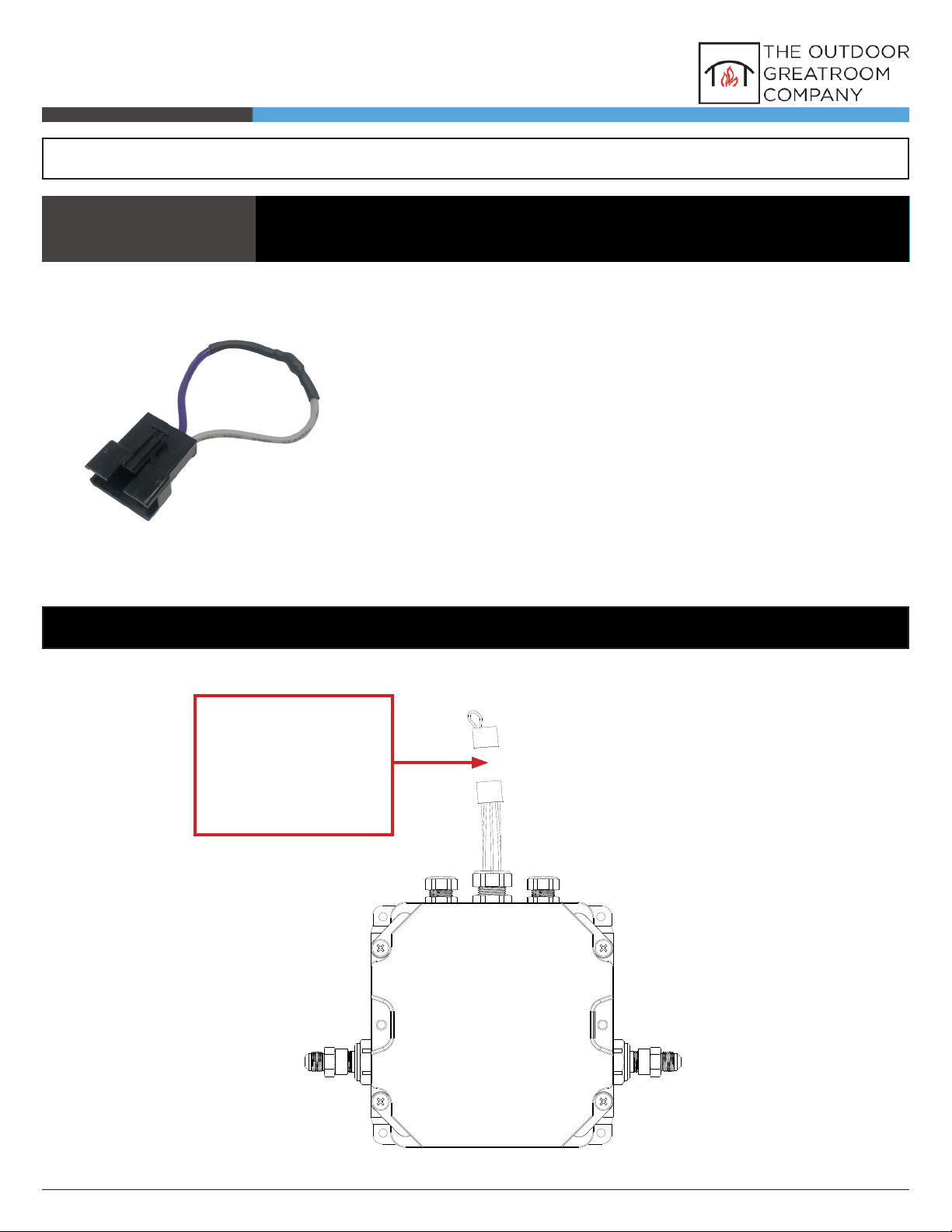
CF-DSI-SB
SWITCH BYPASS
C. ADDITIONAL CONTROL INFORMATION
INSTALLATION DIAGRAM - (CF-DSI-SB)
Connect CF-DSI-SB to
female 5-pin connector on
DSI.
The connectors are keyed
and can only connect one
direction.
Installs on CF-DSI where low-voltage control
switch would normally connect.
Removes manual switch and remote functionality
from CF-DSI
Appliance is then controlled solely by the
high-voltage.
•
•
•

12
www.outdoorrooms.com
42511 REV B : 03-16-2021
WIRING DIAGRAM - (CF-DSI-SB)
CONTROL
MODULE
GAS CONTROL
VALVE
3.3 VDC+
3.3 VDC-
SENSOR/IGNITER
SUPPLY FROM GFCI
RECEPTACLE
110-120VAC

13
www.outdoorrooms.com
42511 REV B : 03-16-2021
A. SQUARE BURNER PLATES
2
BURNER PLATE INFORMATION
INSTALLATION GUIDELINES
BURNER PLATE MODEL
A
MIN (IN.)
A
MAX (IN.)
B
MIN (IN.)
B
MAX (IN.)
C
MIN (IN.)
C
MAX (IN.)
BP24S 1.00 2.50 6.00 N/A 15.00 N/A
BP30S 1.00 5.50 6.00 N/A 15.00 N/A
BP36S 1.00 5.50 6.00 N/A 15.00 N/A
BP42S 1.00 6.00 6.00 N/A 15.00 N/A
A A
B
(VCSV)
C
(DSI)

14
www.outdoorrooms.com
42511 REV B : 03-16-2021
INSTALLATION INSTRUCTIONS
Ensure enclosure meets requirements
detailed in Crystal Fire Plus installation
manual.
Position and if necessary secure burner
plate to enclosure.
Install top material or capstone.
Burner insert can then be connected to
gas and electrical according to the Crystal
Fire Plus instruction manual and lowered
into the burner plate. Ignition wind guard
should be oriented towards cutout in
burner plate.
For BI28 burners, it is necessary to secure
burner insert to burner plate. Remove the
four (4) 1/4”-20 x 3/4” machine screws
from burner plate threaded inserts and
secure BI28 to burner plate through
perimeter drainage holes.
2
3
1.
2.
3.
4.
5.
4
Ignition Wind Guard
5
15
www.outdoorrooms.com
42511 REV B : 03-16-2021
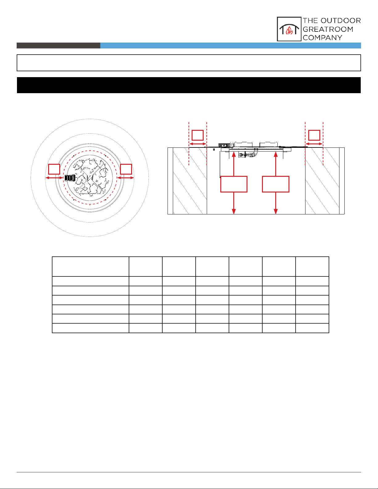
B. ROUND BURNER PLATES
INSTALLATION GUIDELINES
BURNER PLATE MODEL
A
MIN (IN.)
A
MAX (IN.)
B
MIN (IN.)
B
MAX (IN.)
C
MIN (IN.)
C
MAX (IN.)
BP20RD 1.00 2.50 6.00 N/A 15.00 N/A
BP24RD 1.00 4.50 6.00 N/A 15.00 N/A
BP30RD 1.00 2.50 6.00 N/A 15.00 N/A
BP36RD 1.00 5.50 6.00 N/A 15.00 N/A
BP42RD 1.00 6.00 6.00 N/A 15.00 N/A
BP48RD 1.00 6.00 6.00 N/A 15.00 N/A
A A
A A
B
(VCSV)
C
(DSI)
16
www.outdoorrooms.com
42511 REV B : 03-16-2021
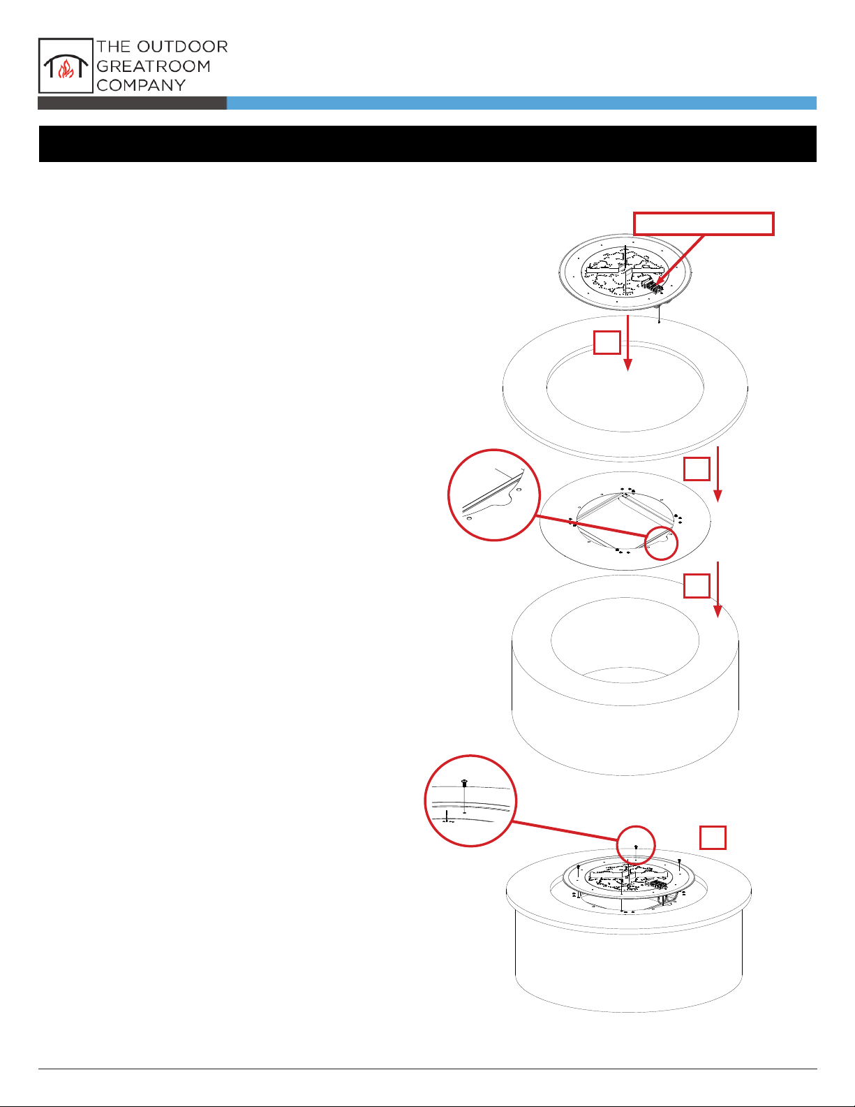
INSTALLATION INSTRUCTIONS
3
Ensure enclosure meets requirements
detailed in Crystal Fire Plus installation
manual.
Position and if necessary secure burner
plate to enclosure.
Install top material or capstone.
Burner insert can then be connected to
gas and electrical according to the Crystal
Fire Plus instruction manual and lowered
into the burner plate. Ignition wind guard
should be oriented towards cutout in
burner plate.
For BI28 burners, it is necessary to secure
burner insert to burner plate. Remove the
four (4) 1/4”-20 x 3/4” machine screws
from burner plate threaded inserts and
secure BI28 to burner plate through
perimeter drainage holes.
1.
2.
3.
4.
5.
4
2
Ignition Wind Guard
5

17
www.outdoorrooms.com
42511 REV B : 03-16-2021
C. LINEAR BURNER PLATES
INSTALLATION GUIDELINES
WIDTH OF
BURNER PLATE (IN.)
A
MIN (IN.)
A
MAX (IN.)
B
MIN (IN.)
B
MAX (IN.)
C
MIN (IN.)
C
MAX (IN.)
D
MIN (IN.)
D
MAX (IN.)
12 .50 1.50 .50 3.00 15.00 N/A 13.00 N/A
18 .50 2.25 .50 3.00 15.00 N/A 13.00 N/A
24 .50 3.50 .50 3.00 15.00 N/A 13.00 N/A
C
(VCSV)
D
(DSI)
B B
A
A

18
www.outdoorrooms.com
42511 REV B : 03-16-2021
INSTALLATION INSTRUCTIONS
Ensure enclosure meets requirements
detailed in Crystal Fire Plus installation
manual.
For burner plates longer than 64 in.,
the two halves of the burner insert
and burner plate must be secured
together with included mending
brackets and hardware.
Position and if necessary secure
burner plate to enclosure.
Install top material or capstone.
Burner insert can then be connected
to gas and electrical according to the
Crystal Fire Plus instruction
manual and lowered into the burner
plate. Thermocouple and igniter lead
should pass through indicated hole on
burner plates.
*Note: For VCSV units, thermocouple
and igniter lead should pass through
indicated hole on burner plate.
1.
2.
3.
4.
5.
2
3
5
4