
Owner's Manual
ELECTRIC START
42" MOWER
6 SPEED TRANSAXLE
LAWN TRACTOR
Model No.
917.272054
• Safety
• Assembly
• Operation
• Maintenance
• Repair Parts
CAUTION:
Read and follow all Safety
Rules and Instructions before
operating this equipment.
For answers toyourquestions
about thisproduct,Call:
1-800-659-5917
Sears Craftsman Help Line
5 am - 5 pm, Mon- Sat
Sears, Roebuck and Co., Hoffman Estates, II 60179
Visit our Craftsman website:www.sears.conVcraftsman
Warranty ............................................... 2
Safety Rules ......................................... 3
Product Specifications.......................... 6
Assembly .............................................. 8
Operation ............................................ 11
Maintenance Schedule ...................... 17
Maintenance ....................................... 17
Service and Adjustments.................... 21
Storage ............................................... 27
Troubleshooting ................................. 28
Repair Parts........................................ 32
Parts Ordedng ..................... Back Cover
LIMITED TWO YEAR WARRANTY ON CRAFTSMAN RIDING EQUIPMENT PARTS
For two (2) years from the date of purchase, if this Craftsman Riding Equipment is
maintained, lubricated and tuned up according to the instructionsin the owner's
manual, Sears will repair or replace, free of charge, any parts found to be defective in
material or workmanship. Warranty service is available free of charge by returningyour
Craftsman riding equipment to your nearest Sears Service Center. In-home warranty
service is available buta trip charge will apply.This warranty appliesonly while this
productis in the United States.
ThisWarranty does notcover:
• Expendable items which become wom dudng normal use, suchas blades, spark
plugs,air cleaners, belts and oil filters.
• Tire replacement _ repair caused by punctures from outside objects, such as nails,
thoms, stumps, or glass.
• Repairs necessary because of operator abuse, includingbut not limited to, damage
caused by towing objects beyond the capability of the dding equipment, impacting
objectsthat bend the frame or crankshaft, or over speeding the engine.
• Repairs necessary because of operator negligence, including but not limited to,
elactdcal and mechanical damage caused by improper storage, failure to use the
proper grade and amount of engine oil, failure to keep the deck clear of flammable
dehds, or the failure to maintain the equipment according to the instructionscon-
tained in the owner's manual.
• Engine (fuel system) cleaning or repairs caused by fuel determined to be contami-
nated or oxidized (stale). In general, fuel should be used within thirty (30) days of its
purchase date.
• Riding equipment used for commercial or rental purposes. A productis "used for
commercial purpose" if is used for any purpose other than single family household
dwellingsor in usage where profit is made.
LIMITED 90 DAYWARRANTY ON BATTERY
For ninety (90) days from date of purchase, if any battery includedwith this riding
equipment proves defective in material or workmanship and our testing determines the
battery will nothold a charge, Sears will replace the batteryat no charge. Warranty
service is available free of charge by retuming your Craftsman dding equipment to
your nearest Sears Service Center. In-home warranty service is available but a trip
charge will apply.This warranty applies only while this product is in the United States.
TO LOCATE THE NEAREST SEARS SERVICE CENTER OR TO SCHEDULE IN-HOME
WARRANTY SERVICE, SIMPLY CONTACT SEARS AT 1-800-4-MY-HOME
This Warranty gives you specific legal rights, and you may also have other rightswhich
may vary from state tostate.
Sears, Roebuck and Co., D/817 WA, Hoffman Estates, IL 60179
2
IMPORTANT: This cuttingmachine is capable of amputating hands and feet and
throwingobjects. Failure to observe the followingsafety instructionscould result in
serious injury or death.
I. GENERAL OPERATION
• Read, understand, and follow all
instructionsin the manual and on the
machine before starting.
• Onl_ allow responsibleadults, who are
famdiar with the instructions,to operate
the machine.
• Clear the area of objects such as
reeks, toys,wire, etc., whichcould be
picked up and thrown by the blade.
• Be sure the area is clear of other
people before mowing. Stop machine
ifanyone enters the area.
• Never carry passengers.
• Do not mow in reverse unless abso-
lutely necessary. Always lookdown
and behind before and while backing.
• Be aware of the mower discharge
directionand do not point it at anyone.
Do not operate the mower without
either the entire grass catcher or the
guard in place.
• Slow down before turning.
• Never leave a running machine
unattended. Always turn off blades, set
parking brake, stop engine, and
remove keys before dismounting.
• Turn off blades when notmowing.
• Stop engine before removing grass
catcher or unclogging chute.
• Mow only in daylight or good artificial
light.
• Do not operate the machine while
under the influence of alcohol or drugs.
• Watch for traffic when operating near or
crossing roadways.
• Use extra care when loading or
unloading the machine into a trailer or
truck.
• Data indicates that operators, age 60
i/aearaand above, are involved in a
rge percentage of dding mower-
related in udes. These et:!eratora
should eva uate their ability to operate
the riding mower safely enough to
protect themselves and others from
serious injury.
• Keep machinefree ofgrass, leavesor
other debris build-upwhich can touch
hotexhaust / engine partsand bum. Do
notallow the mower deck to plow leaves
or otherdebds which can cause build-
up to occur.Clean any oil or fuel
spilla_e before operating or storingthe
machine. Allow machine to cool before
storage. 3
I1.SLOPE OPERATION
Slopes are a major factor related to loss-of-
control and tipover accidents, which can
result in severe injuryor death. All slopes
require extra caution. If you cannotbeck up
the slope or if you feel uneasy on it, do not
mow it.
DO:
• Mow up and down slopes, not across.
• Remove obstacles such as rocks,tree
tirebs,etc.
Watch for holes, ruts,or bumps.
Uneven terrain could overture the
machine. Ta/I grass can hide obstacles.
Use slow speed. Choose a low gear so
that you will nothave to stop or shift
while on the slope.
Follow the manufacturer's recommen-
dations for wheel weights or counter-
weights to improve stability.
Use extra care with grass catchers or
other attachments. These can change
the stabilityof the machine.
Keep all movement on the slopes slow
and gradual. Do not make sudden
changes in speed or direction.
Avoid starting or stoppingon a slope. If
tires lose traction, disengage the
blades and proceed slowly straight
down the slope.
DO NOT:
• Do not turn on slopes unless neces-
sary, and then, turn slowly and gradu-
ally downhill, if possible.
• Do notmow near drepoffs, ditches, or
embankments, The mower could
suddenly turn over if a wheel is over the
edge of a cliff or ditch,or if an edge
caves in.
• Do not mow on wet grass. Reduced
traction could cause sliding.
• Do not try to stabilize the machine by
putting yourfoot on the ground.
• Do not use grass catcher on steep
slopes.
III.CHILDREN
Tragicaccidentscanoccuriftheoperator
isnotalerttothepresenceofchildren.
Childrenareoftenattractedtothe
machineandthemowingactivity.Never
assume that children will remain where
you last saw them.
• Keep children out of the mowing area
and under the watchful care of another
responsible adult.
• Be alert and turn machine off if children
enter the area.
• Before and when backing, look behind
and down for small children.
• Never carry children. They may falloff
and be seriously injured or interfere
with safe machine operation.
• Never allow children to operate the
machine.
• Use extra care when approaching blind
comers, shrubs, trees, or other objects
that may obscure vision.
IV. SERVICE
• Use extra care in handlinggasoline
and other fuels. They are flammable
and vapors are explosive.
-Use only an approved container.
- Never remove gas cap or add fuel
with the engine running. Allow
engine to cool before refueling. Do
not smoke.
- Never refuel the machine indoors.
-Never store the machine or fuel
container inside where there is an
open flame, such as a water heater.
• Never run a machine inside a closed
area.
• Keep nuts and bolts, especiaUyblade
attachment halts, tight and keep
equipment in good condition.
• Never tamper with safety devices.
Check their proper operation regularly.
• Keep machine free ofgrass, leaves, or
other debds build-up. Clean oil or fuel
spillage. Allow machine to cool before
stodng.
• Stop and inspectthe equipment if you
strike an object. Repair, if necessary,
before restarting.
• Never make adjustments or repairs
with the engine running.
• Grass catcher components ore subject
to wear, damage, and deterioration,
which could expose moving partsor
allow objects to be thrown. Frequently
check componentsand replace with
manufacturer's recommended parts,
when necessary.
• Mower blades are sharp and can cut.
Wrap the blade(s) or wear gloves, and
use extra caution when servicingthem.
• Check brake operation frequently.
Adjust and service as required.
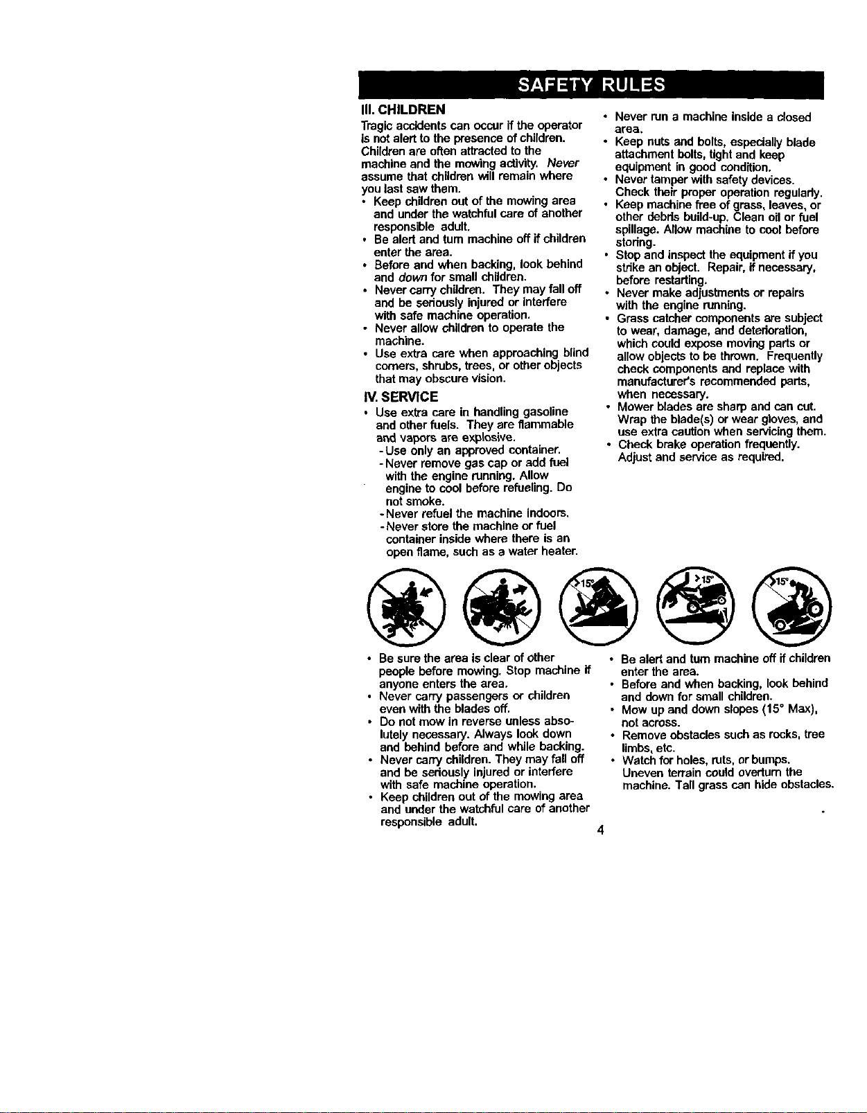
@@@@@
• Be sure the area is clear of other
people before mowing. Stop machine if
anyone enters the area.
• Never carry passengers or children
even with the blades off.
• Do not reow irl reverse unless abso-
lutely necessary. Always look down
and behind before and while backing.
• Never carrychildren. They may fall off
and be sedously injuredor interfere
with safe machine operation.
• Keep children out of the mowing area
and under the watchful care of another
responsible adult.
• Be alert and turn machine off if children
enter the area.
• Before and when backing, look behind
and down for small children.
• Mow up and down slopes (15° Max),
not across.
• Remove obstacles such as rocks,tree
limbs, etc.
• Watch for holes, ruts, or bumps.
Uneven terrain could overturn the
machine. Tall grass can hide obstacles.
4
• Use slow speed. Choose a low gear so
that you willnot have to stopor shift
while on the stope.
• Avoid startingor stopping on a slope. If
tires lose traction,disengage the
blades and proceed slowly straight
down the slope.
• If machine stops while going uphill,
disengage blades, shift into reverse
and back down slowly.
• Do not turn on slopes unless Races-
sery, and then, turn slowlyand gradu-
ally downhill,if possible.
_Look for this symbol to point out
importantsafety precautions. It means
CAUTION!I! BECOMEALERTI!! YOUR
SAFETY IS INVOLVED.
,_ CAUTION: In order to prevent
accidental starting when setting up,
transporting, adjusting or making repairs,
always disconnect spark plug wire and
place wire where itcannot contact spark
plug.
_ CAUTION: Do not coast down a hill
in neutral, you may lose control of the
tractor.
CAUTION: Towonlythe attachments
that are recommended by and comply
with specificationsof the manufacturer of
your tractor. Use common sense when
towing. Operate only at the lowest
possiblespeed when on a slope. Too
heavy of a load, while on a slope, is
dangerous. Tires can lose tractionwith
the ground and cause you to lose control
ofyour tractor.
_WARNING: Engine exhaust, some of
its constituents,and certain vehicle
COmponentscontain or emit chemicals
known to the State of California to cause
cancer and birth defects or other repro-
ductive harm.
_WARNING: Batteryposts, terminals
and related accessories contain lead and
lead compounds, chemicals known to the
State of California to cause cancer and
birthdefects or other reproductiveharm.
Wash hands after handling.
5
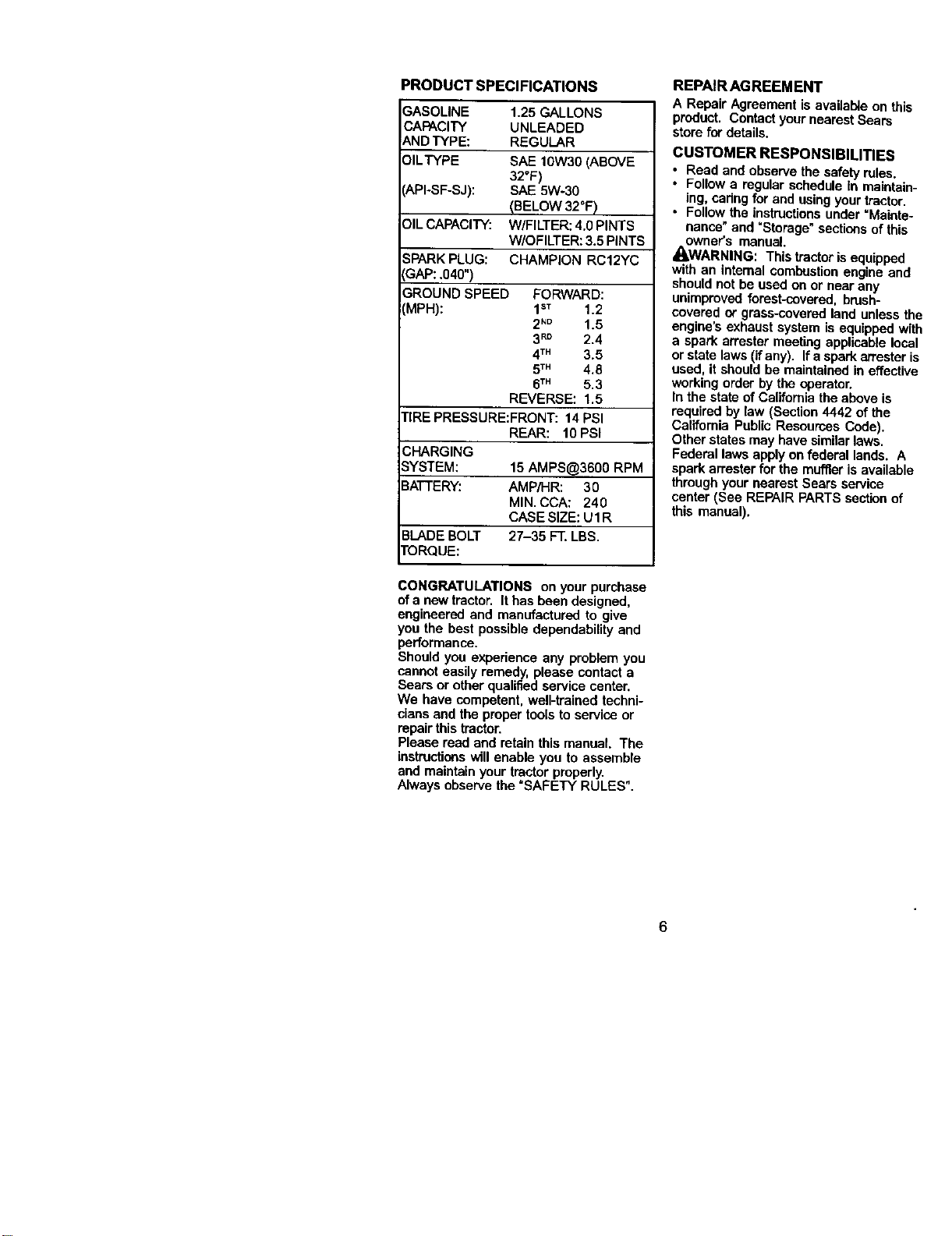
PRODUCTSPECIFICATIONS
3ASOLINE 1.25 GALLONS
CAPACITY UNLEADED
_,NDTYPE: REGULAR
31LTYPE ShE 10W30 (ABOVE
32°F)
'API-SF-SJ): SAE 5W-30
(BELOW 32°F)
DILCAPACITY: W/FILTER: 4.0 PINTS
W/OFILTER: 3.5 PINTS
SPARK PLUG: CHAMPION RC12YC
:GAP:.040")
3ROUND SPEED FORWARD:
'MPH): 1sT 1.2
2N° 1.5
3RD 2.4
4TM 3.5
5TM 4.8
6TM 5.3
REVERSE: 1.5
TIRE PRESSURE:FRONT: 14 PSI
REAR: 10 PSI
CHARGING
SYSTEM: 15 AMPS@3600 RPM
BATTERY: AMP/HR: 30
MIN. CCA: 240
CASE SIZE: U1R
BLADE BOLT 27-35 FT. LBS.
TORQUE:
CONGRATULATIONS on your purchase
of a new tractor. It has been designed,
engineered and manufactured to give
you the best possible dependability and
performance.
Should you experience any problem you
cannot easily remedy, please contact a
Sears or other qualified service center.
We have competent, well-trained techni-
cians and the proper tools to service or
repair this tractor.
Please reed and retain this manual. The
instructionswill enable you to assemble
and maintain your tractor properly.
Always observe the "SAFETY RULES".
REPAIR AGREEMENT
A Repair Agreement is avaUab_eon this
product. Contactyour nearest Sears
store for details.
CUSTOMER RESPONSIBILITIES
• Read and observe the safety rules.
• Follow a regular schedule In maintain-
ing, Cadng for and using your tractor.
Follow the instructionsunder =Mainte-
nance" and "Storage" sections of this
owner's manual.
_I,WARNING: Thistractor is equipped
with an internal combustion engine and
should not be used on or near any
unimproved forest-cevered, brush-
covered or grass-covered land unless the
engine's exhaust system is equipped with
a spark an'ester meeting applicable local
or state laws (if any). If a spark an'ester is
used, it should be maintained in effective
working order by the operator.
In the state of California the above is
required by law (Section 4442 of the
California Public Resources Code).
Other states may have similarlaws.
Federal laws apply on federal lands. A
spark arrester for the muffler is available
through your nearest Sears service
center (See REPAIR PARTS sectionof
this manual).
6
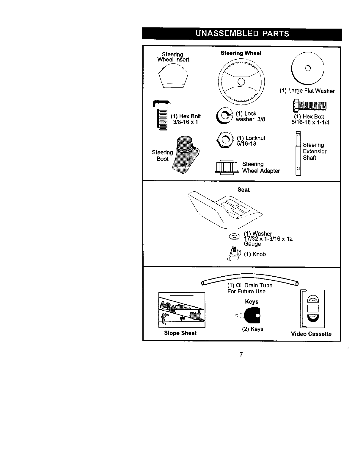
Steering
WheelInsert
C2
I_(1) Hex Bolt
3/8-16 x 1
Steering
ooo,
Steering Wheel
(1) Lockwasher 3/8
(1) Locknut
5/16-18
_ Steering
Wheel Adapter
\
(1) Large Flat Washer
(1) Hex Bolt
5/16-18 x 1-1/4
t teering
Extension
Shaft
\
Seat
__%.._,(1) Washer
17/32 x 1-3/16 x 12
Gauge
_(1) Knob
Slope Sheet
For Future Use
Keys
I1
(2) Keys
Video Cassette
Yournew tractor has been assemb|ed at the factory with exceptionof those partslel
unassembled for shipping purposes, To ensure safe and proper operation of your
tractor all parts and hardware you assemble must he tightened securely.Use the
correct toolsas necessary to insure proper tightness. Review the video cassette be
you begin,
TOOLS REQUIRED FOR
ASSEMBLY
A socket wrench set will make assembly
easier. Standard wrench sizes you need
are listed below.
(1) 9/16"wrench (1) Pliers
(2) 1/2"wrench (1) Utility knife
(1) Tire pressure gauge
When right or left hand is mentioned in
this manual, it means, from your pointof
view, when you are in the operating
position (seated behind the steedng
wheel),
TO REMOVETRACTOR FROM
CARTON
UNPACK CARTON
1. Remove all accessible loose parts
and partscartons from carton.
2. Cut. from top to bottom, along lines on
all four corners of carton, and lay
panels flat.
3. Check for any additional loose parts
or cartons and remove.
BEFORE REMOVINGTRACTOR
FROM SKID
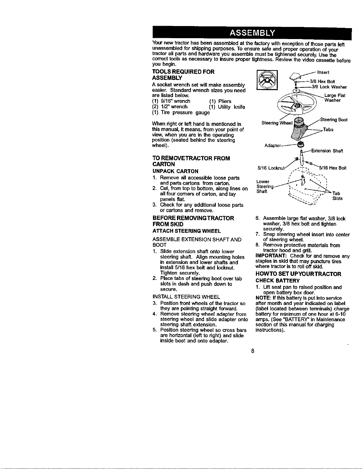
ATTACHSTEERINGWHEEL
ASSEMBLE EXTENSION SHAFT AND
BOOT
1. Slide extension shaft onto lower
steering shaft. Align mounting holes
in extension and lower shafts and
install 5/16 bex bolt and _ocknut.
Tighten securely.
2. Place tabs of steering boot over tab
slotsin dash and push down to
secure.
INSTALL STEERING WHEEL
3, Position front wheels of the tractor so
they are pointing straight forward.
4. Remove steedng wheel adapter from
steering wheel and slide adapter onto
steering shaft extension.
5. Position steering wheel so cross bars
are horizontal (left to right) and slide
inside boot and onto adapter.
6. Assemble large flat washer, 3/8 Ioc
washer, 3/8 hex bolt and lighten
securely.
7. Snap steering wheel insert into cel
of steedng wheel.
8. Remove protective matedals from
tractor hood and gdll.
IMPORTANT: Check for and remove
staples in skid that may puncturetires
where tractor isto rolloff skid.
HOWTO SET UPYOURTRACTOR
CHECK BATTERY
1. Lift seat pan to raisedposition end
open batterybox door.
NOTE: If this batteryisput intoservice
after month and year indicated on lab,
(label located between terminals) cha
batteryfor minimum of one hour at 6-1
amps. (See "BATTERY" in Maintenanc(
section of this manual for charging
instructions).
Door
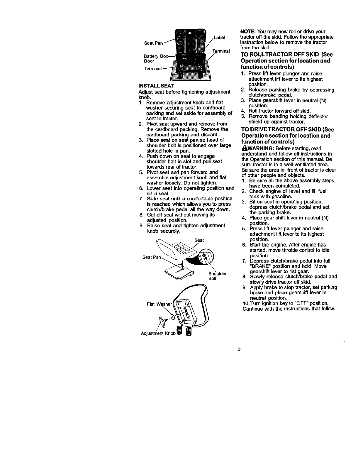
INSTALL SEAT
Adjust seat before tighteningadjustment
knob,
1. Remove adjustment knob end fiat
washer secudng seat to cardboard
packing and set aside for assembly of
seat to tractor.
2. Pivot seat upward and remove from
the cardboard packing, Remove the
cardboard packing and discard,
3. Place seat on seat pan so head of
shoulder bolt is positioned over large
slotted hole in pan.
4. Push down on seat to engage
shoulder bolt in slot and pull seat
towardsroar of tractor.
5. Pivot seat and pan forward end
assemble adjustment knob and fiat
washer loosely. Do not tighten.
6. Lower seat into operating position and
sit in seat,
7. Slide seat until a comfortable position
is reached which allows you to press
clutch/brake pedal ell the way down.
8. Get off seat withoutmoving its
adjusted position.
9. Raise seat and tighten adjustment
knob securely,
Seat
Bolt
Flat Washer
NOTE: You may now rollor drive your
tractor off the skid. Follow the appropriate
instructionbelow to remove the tractor
from the skid.
TO ROLLTRACTOR OFF SKID (See
Operation section for location and
function of controls)
1. Press lift lever plunger and raise
attachment liftlever to its highest
position.
2. Release parking brake by depressing
clutch/brake pedal.
3. Place gearshift lever in neutral {N)
position,
4. Roll tractorforward off skid.
5. Remove banding holding deflector
shield up against tractor.
TO DRIVETRACTOR OFF SKID (See
Operation section for location and
function of controls)
,_WARNING: Beforestarting, read,
understand and follow all instructionsin
the Operation section of this manual. Be
sure tractoris in a well-ventilated area.
Be sure the area in front oftractor isclear
of other people and objects.
1. Be sure all the above assembly steps
have been completed,
2. Check engine oil level and fill fuel
tank with gasoline.
3. Sit on seat in operating position,
depress elutch/brake pedal and set
the parking brake.
4. Place gear shiftlever in neulfal (N)
position.
5, Press lift lever plunger and raise
attachment liftlever to its highest
position.
6. Start the engine. After engine has
started, move throttle controlto idle
position.
7. Depress clutch/broke pedal intofull
"BRAKE" position and hold. Move
gearshift lever to 1stgear.
8. Slowly release clutch/brake pedal and
slowlydrive tractor off skid.
9. Apply brake tostop tractor, set parking
brake and place gearshift lever in
neutral position.
10.Turn ignitionkey to "OFF" position.
Continue with the instructionsthat follow.
9
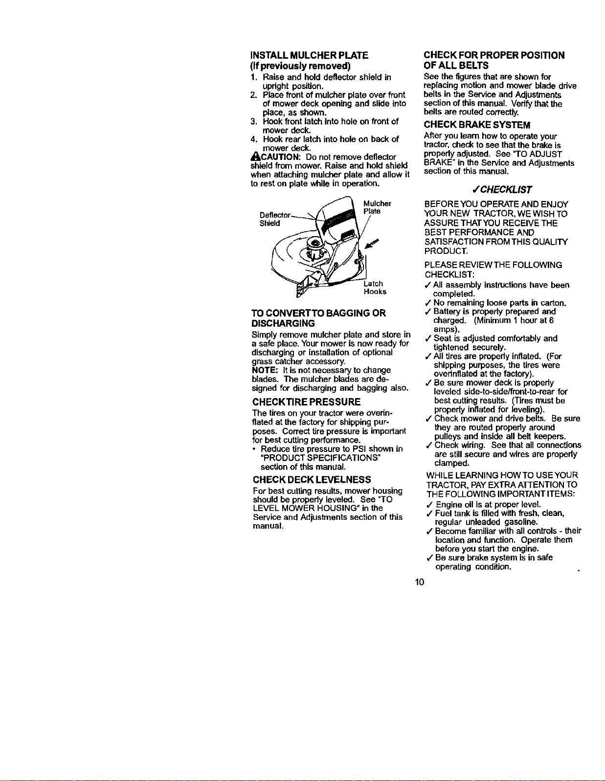
INSTALL MULCHER PLATE
(If previously removed)
1. Raise and hold deflector shield in
updght position.
2. Place front of mulcher plate over front
of mower deck opening and slide into
place, as shown.
3. Hook front latch into hole on front of
mower deck.
4. Hook rear latch intohole on back of
mower deck.
_CAUTION: Do not remove deflector
shield from mower. Raise and hold shield
when attaching mulcher plate and allow it
to rest on plate while in operation.
Mulcher
Plate
Shield
Latch
Hooks
TO CONVERTTO BAGGING OR
DISCHARGING
Simply remove mulcher plate and store in
a safe place. Yourmower is now ready for
discharging or installation of optional
grass catcher accessory.
NOTE: It is not necessary to change
blades. The mulcber blades are de-
signed for discharging and bagging also.
CHECKTIRE PRESSURE
The tires on your tractor were ovedn-
fiated at the factory for shippingpur-
poses. Correct tire pressure is important
for best cutting performance.
• Reduce tirepressure to PSI shown in
"PRODUCT SPECIFICATIONS"
section of this manual.
CHECK DECK LEVELNESS
For best cuttingresults, mower housing
should be propedy leveled, See =TO
LEVEL MOWER HOUSING" in the
Service and Adjustments section of this
manual,
CHECK FOR PROPER POSITION
OF ALL BELTS
See the figures that are shown for
replacing motion and mower blade ddve
belts in the Service and Adjustments
section ofthis manual. Vedfy that the
belts are routed correctly.
CHECK BRAKE SYSTEM
After you learn how to operate your
tractor,check tosee thatthe brake is
propody adjusted. See "TO ADJUST
BRAKE" in the Service and Adjustments
section of this manual.
/CHECKLIST
BEFORE YOU OPERATE AND ENJOY
YOUR NEW TRACTOR, WE WISH TO
ASSURE THATYOU RECEIVE THE
BEST PERFORMANCE AND
SATISFACTION FROM THIS QUALITY
PRODUCT,
PLEASE REVIEWTHE FOLLOWING
CHECKLIST:
,/All assembly instructions have been
completed.
/ No remaining loose parts in carton.
4" Battery is propedy prepared and
charged. (Minimum 1 hour at 6
amps).
,/Seat is adjusted comfortablyand
tightened securely.
,/All tires are propedy inflated. (For
shipping purposes, the tires were
ovednfiatnd at the factory).
•/ Be sure mower deck is propody
leveled side-to-side/front-to-rear for
bestcutting results. (Tires must be
propedy inflated for leveling).
,/Check mower and ddve belts, Be sure
they are muted propody around
pulleys and inside all belt keepers.
,/Check wiring. See that all connections
are stillsecure and wires are propedy
clamped.
WHILE LEARNING HOW TO USE YOUR
TRACTOR, PAYEXTRA A]-FENTION TO
THE FOLLOWING IMPORTANT ITEMS:
v' Engine oil is at proper level.
,/Fuel tank Is filled with fresh, clean,
regular unleaded gasoline.
,/Become familiar with all controls - their
location and function. Operate them
before you start the engine.
,/Be sure brakesystem is in safe
operating condition.
10
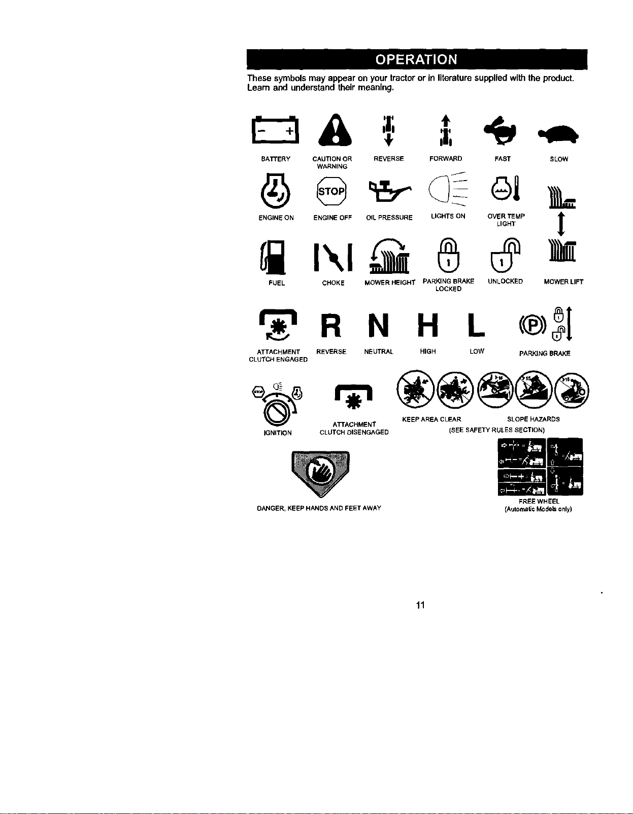
These symbolsmay appear on your tractor or in literature supplied with the product.
Learn and understand their meaning.
A =`
BATTERY CAUTION OR REVERSE FORWARD FAST SLOW
WARNING
ENGINE ON ENGINE OFF OILPRESSURE LIGHTS ON OVER TEMP
LIGHT
FUEL CHOKE MOWER HEIGHT PARKING BRAKE UNLOCKED
LOCKED
MOWER LIFT
r_'_ R N H L
ATTACHMENT REVERSE NEUTRAL HIGH LOW PARKING BRAKE
CLUTCH ENGAGED
ATTACHMENT KEEP AREA CLEAR SLOPE HAZARDS
IGNITION CLUTCH DISENGAGED
DANGER, KEEP HANDS AND FEET AWAY
(SEE SAFETY RULES SECTION)
FREEWHEEL
(Automate Models only)
11
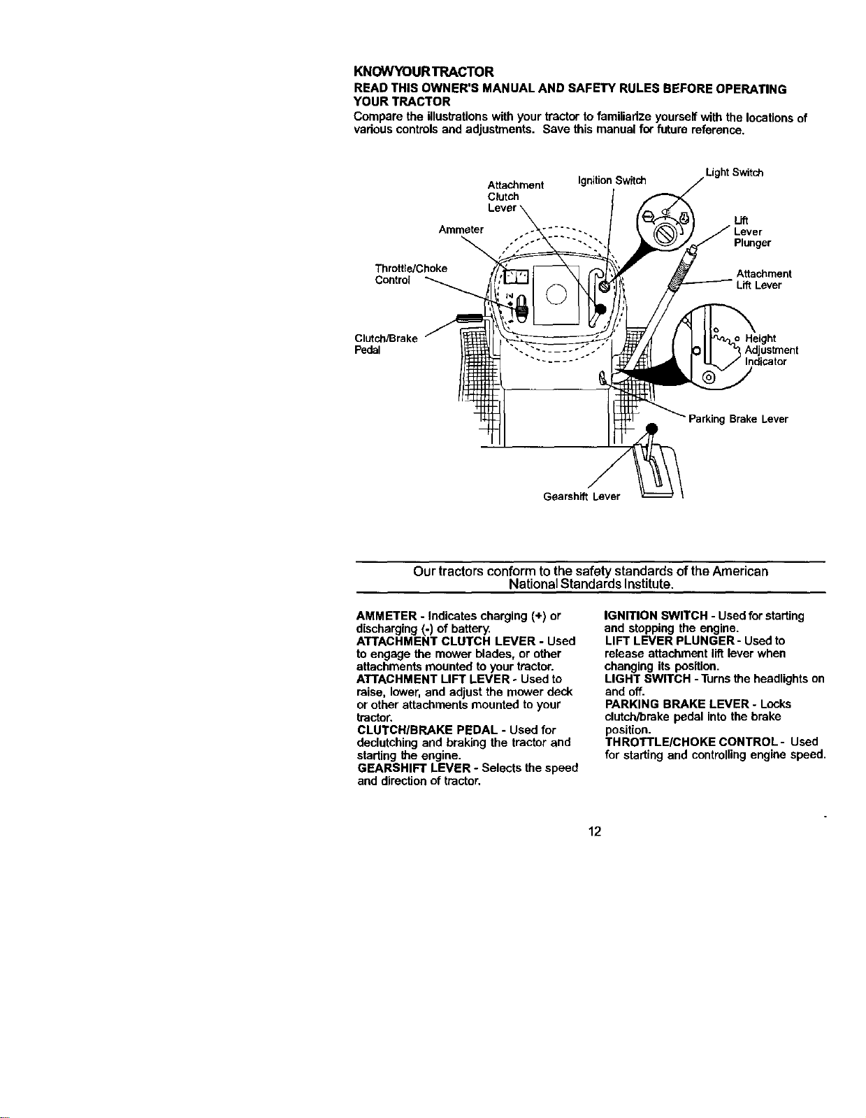
KNOWYOURTRACTOR
READ THIS OWNER'S MANUAL AND SAFETY RULES BEFORE OPERATING
YOUR TRACTOR
Compare the illustrationswith your tractor to familiarize yourselfwith the locationsof
variouscontrolsand adjustments. Save this manual for future reference.
Attachment IgnitionSwitch
Clutch
Ammeter ..... - ..
Throffie/Choke
Control
Light Switch
Lift
Plunger
Attachment
Lift Lever
Clutch/Brake
Pedal
Height
Adjustment
Parking Brake Lever
Gearshift Lever
Our tractorsconformto the safety standards of the American
National Standards Institute.
AMMETER - Indicates charging (+) or
discharging (-) of battery.
ATTACHMENT CLUTCH LEVER - Used
to engage the mower blades, or other
attachments mounted to your tractor.
ATTACHMENT LIFT LEVER oUsed to
raise, lower, and adjust the mower deck
or other attachments mounted to your
tractor.
CLUTCH/BRAKE PEDAL - Used for
declutching and braking the tractor and
starting the engine.
GEARSHIFT LEVER - Selects the speed
and direction of tractor.
IGNITION SWITCH - Used forstarting
and stopping the engine.
LIFT LEVER PLUNGER - Usedto
release attachment llftlever when
changing its position.
LIGHT SWITCH -Turns the headlights on
and off.
PARKING BRAKE LEVER - Locks
clutch/brake pedal into the brake
position.
THROTTLEICHOKE CONTROL- Used
for starting and controllingengine speed.
12
The operationof any tractor can resultin foreign objects thrown into
the eyes, which can resultin severe eye damage. Alwayswear safety
glasses or eye shields while operating your tractor or performing any
adjustments or repairs. We recommend a wide visionsafety mask
over spectacles or standard safety glasses.
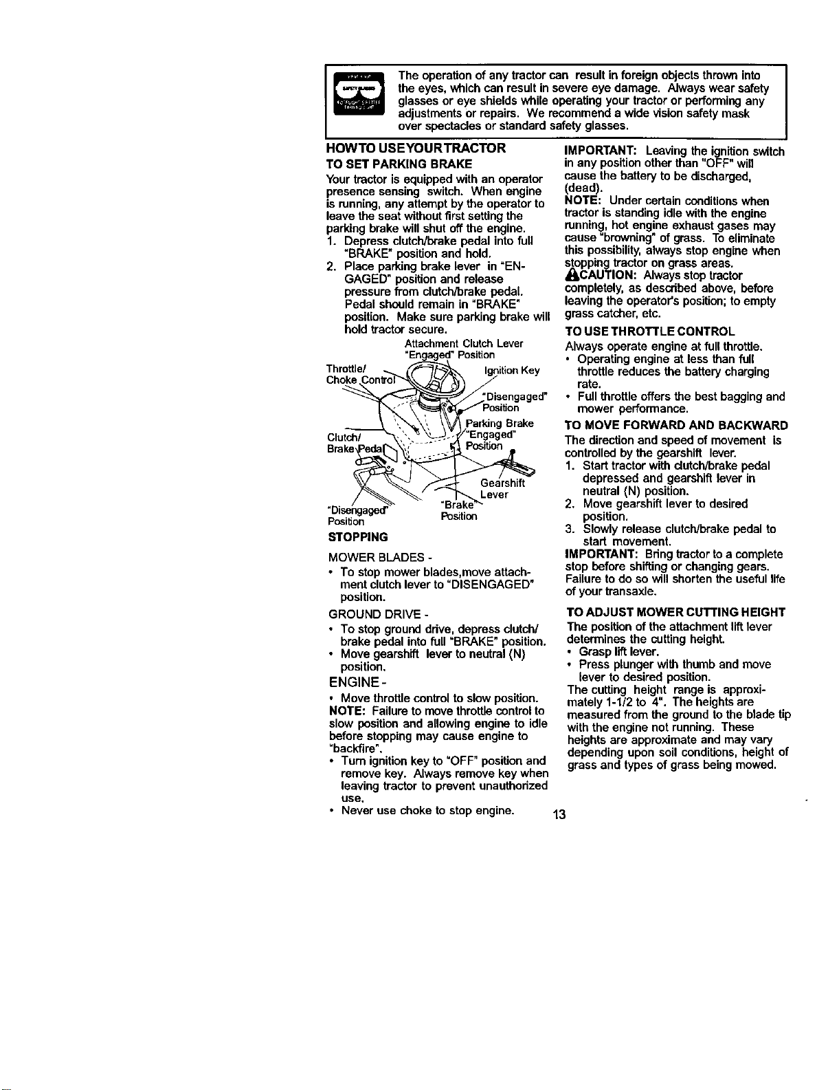
HOWTO USEYOURTRACTOR
TO SET PARKING BRAKE
Your tractoris equipped with an operator
presence sensing switch. When engine
is running, any attempt by the operator to
leave the seat withoutfirst setting the
parking brake will shut offthe engine.
1. Depress clutch/brake pedal into full
"BRAKE" position and hold.
2. Place parking brake lever in "EN-
GAGED" posiUonand release
pressure from clutch/brake pedal.
Pedal should remain in "BRAKE"
position. Make sure parking brake will
hold tractorsecure.
AttachmentClutchLever
+Engaged"Position
Throttle/
Choke
"Disengaged"
Clutch/
Brake,
Brake
Lever
Position Position
STOPPING
MOWER BLADES -
• To stop mower blades,meve attach-
ment clutchlever to "DISENGAGED"
position.
GROUND DRIVE -
• To stop ground ddve, depress clutch/
brake pedal into full "BRAKE" position.
• Move gearshift lever to neutral (N)
position.
ENGINE-
• Move throttle control to slow position.
NOTE: Failure to movethrottle controlto
slow position and allowing engine to idle
before stoppingmay cause engine to
"backfire".
• Turn ignition key to "OFF" pesiUon and
remove key. Always remove key when
leaving tractor to prevent unauthodzed
use,
• Never use choke tostop engine.
IMPORTANT: Leaving the ignitionswitch
in any positionother than "OFF" will
cause the battery to be discharged,
(dead).
NOTE: Under certain conditionswhen
tractor is standing idlewith the engine
running, hot engine exhaust gases may
cause "browning" of grass. Toeliminate
this possibility,always stop engine when
_Ocppingtractor on grass areas.
AUTION: Alwaysstop tractor
completely, as described above, before
leaving the operator's position;to empty
grass catcher, etc.
TO USE THROTTLE CONTROL
Always operate engine at full throttle.
• Operating engine at less then full
throttle reduces the battery charging
rate.
• Full throttle offers the best bagging and
mower performance.
TO MOVE FORWARD AND BACKWARD
The direction and speed of movement is
controlledby the gearshift lever.
1. Start tractor with clutch/brake pedal
depressed and gearshift lever in
neutral (N) position.
2. Move gearshift lever to desired
position.
3. Slowly release clutch/brake pedal to
start movement,
IMPORTANT: Bring tractorto a complete
stop before shiftingor changing gears.
Failure to do so will shorten the usefullife
of your transaxle.
TO ADJUST MOWER CUTTING HEIGHT
The positionof the attachment liftlever
determines the cutting height.
• Grasp liftlever.
• Press plunger with thumb and move
lever to desired position.
The cutting height range is approxi-
mately 1-1/2 to 4". The heightsare
measured from the ground to the blade tip
with the engine not running. These
heightsare approximate and may vary
depending upon soil conditions,height of
grass and types of grass being mowed.
13
• The average lawn should be cut to
approximately 2-1/2 inches during the
cool season and to over 3 inches
dudng hot months. For healthier and
better lookinglawns, mow often and
after moderate growth.
• For best cuttingperformance, grass
over 6 inches in height should be
mowed twice, Make the first cut
relativelyhigh; the second to desired
height,
TO ADJUST GAUGE WHEELS
Gauge wheels are propedy adjusted
when they are slightlyoff the ground
when mower isat the desired cutting
height in operating position. Gauge
wheels then keep the deck in proper
positionto help prevent scalping in most
terrain conditions.
NOTE: Adjust gauge wheels with tractor
on a flat level surface.
1. Adjust mower to desired cutting height
(See _TOADJUST MOWER CUTTING
HEIGHT" in the Operation section of
this manual).
2. With mower in desired height of cut
position, gauge wheels should be
assembled so they are slightlyoff the
ground. Install gauge wheel in
appropriate hole with shoulder bolt, 3/
8 washer, and 3/8-16 Iocknut and
tighten securely.
3. Repeat for opposite side installing
gauge wheel in same adjustment
hole.
Gauge
Wheel
3/8-16-
Locknut
Shoulder
3/8 _/_Bolt
Gauge Wheel
TO OPERATE MOWER
Your tractor is equipped with an operator
presence sensing switch. Any attempt by
the operator to leave the seat with the
engine running and the attachment
clutchengaged willshut off the engine.
1. Select desired height of cut.
2. Start mower blades by engaging
attachment clutch control.
TO STOP MOWER BLADES -
disengage attachment clutch control.
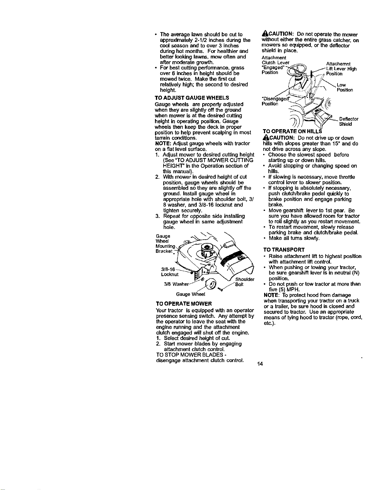
_I_CAUTION: Do not operate the mower
withouteither the entiregrass catcher, on
mowers so equipped, or the deflector
shield in place.
Attachment
ClutchLever Attachemnt
=Engaged" High
Position , Position
Low
Position
Position
Deflector
Shield
TO OPERATE ON HILLS
_CAUTION: Do not drive upor down
hillswith slopes greater than 15" and do
notdrive across any slope,
• Choose the slowest speed before
starting up or down hills.
• Avoid stopping or changingspeed on
hills,
• If slowing isnecessary, move throttle
control lever to slower position.
• If stopping is absolutelynecessary,
push clutch/brake pedal quicklyto
brake position and engage parking
brake.
• Move gearshift lever to 1stgear. Be
sure you have allowed room for tractor
to roll slightlyas you restartmovement.
• To restart movement, slowly release
parking brake and clutch/brake pedal.
• Make all tums slowly.
TO TRANSPORT
• Raise attachment liftto highest position
with attachment liftcontrol.
• When pushing or towing yourtractor,
be sure gearshift lever is in neutral (N)
position.
• Do not pushor tow tractorat more than
five (5) MPH.
NOTE: To protect hoodfrom damage
when transportingyour tractor on a truck
or a trailer, be sure hood isclosed and
secured to tractor. Use an appropriate
means of tyinghood to tractor (rope, cord,
etc.).
t4
TOWING CARTS AND OTHER
ATTACHMENTS
Tow onlythe attachments that are
recommended by and comply with
specificationsof the manufacturer of your
tractor.Use common sense when towing.
Too heavy of a load, while on a slope, is
dangerous. Tires can lose tractionwith the
ground and cause you to lose controlof
your tractor.
BEFORE STARTING THE ENGINE
CHECK ENGINE OIL LEVEL
The engine in your tractor has been
shipped, from the factory,already filled
with summer weight oil.
f. Check engine oilwith tractoron level
ground.
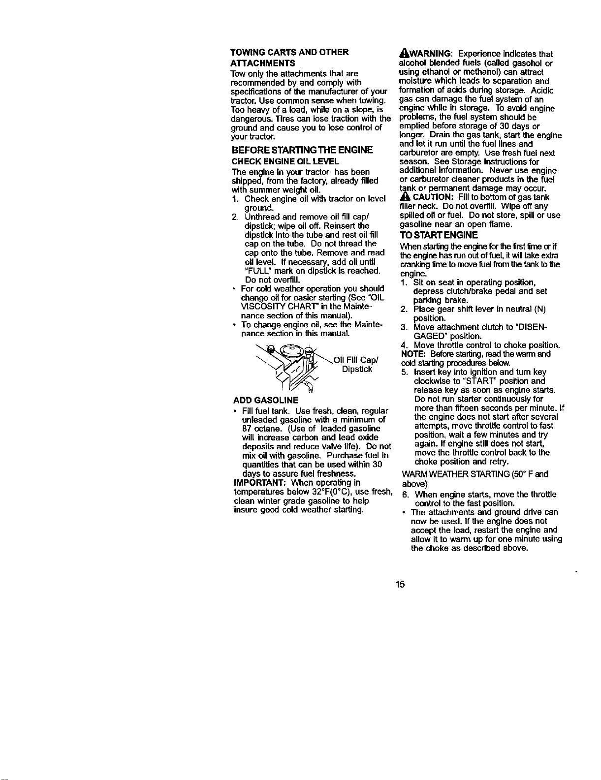
2. Unthread and remove oil fill cap/
dipstick;wipe oil off, Reinsert the
dipstick intothe tube and rest oil fill
cap on the tube. Do not thread the
cap onto the tube. Remove and read
oil level. If necessary, add oil until
=FULL" mark on dipstickis reached.
Do not overfill.
• For cold weather operationyou should
change oilfur easier starting(See "OIL
VISCOSITY CHART" in the Mainte-
nance section of this manual).
• To change engine oil, see the Mainte-
nance section in this manual.
Oil Fill Cap/
Dtpsteck
ADD GASOLINE
• Fillfuel tank. Use fresh, clean, regular
unleaded gasoline with a minimum of
87 octane. (Use of leaded gasoline
will increase carbon and lead oxide
depositsand reduce valve life). Do not
mix oil with gasoline. Purchase fuel in
quantitiesthat can be used within 30
days to assure fuel freshness.
IMPORTANT: When operatingin
AOAWARNING: Experience indicatesthat
alcohol blended fuels (called gasohol or
using ethanol or methanol) can attract
moisture which leads to separation and
formation ofacids dudng storage. Acidic
gas can damage the fuel system of an
engine while in storage. To avoid engine
problems, the fuel system should be
emptied before storage of 30 days or
longer. Drain the gas tank, start the engine
and letit run untilthe fuel lines and
carburetor are empty. Use fresh fuel next
season. See Storage Instructionsfor
additional information. Never use engine
or carburetor cleaner products in the fuel
_k or permanent damage may occur.
CAUTION: Fillto bottomofgas tank
filler neck. Donot overfill. Wipe offany
spilled oil or fuel. Do not store, spillor use
gasoline near an open flame.
TO START ENGINE
Whenstarlingtheeagine furthefirst time orif
theenginehasrunoutoffuel, itwiqtakeextra
crenklegitma tomovefuel from thetanktothe
engine.
1. Sit on seat in operating position.
depress clutch/brake pedal and set
parking brake.
2. Place gear shift lever in neutral(N)
position.
3. Move attachment clutchto =DISEN-
GAGED" position.
4. Move throttle control to choke position.
NOTE: Beforestarting,readthe warm and
coldsta_ng prcoedumsbelow.
5. Insert key intoignition and tum key
clockwise to =START" positionand
release key as soon as engine starts.
Do not run starter continuouslyfor
morethan fifteen seconds per minute. If
the engine does not start after several
attempts, move throttlecontroltofast
position,wait a few minutesand try
again. If engine stilldoes not start,
move the throttlecontrolback to the
choke positionand retry.
WARMWEATHER STARTING(50° F and
above)
temperatures below 32°F(0°C), use fresh, 6. When engine starts, move the throttle
clean winter grade gasoline to help control to the fast position.
insure goad cold weather starting. • The attachments and groundddve can
now be used. If the engine does not
accept the load, restart the engine and
allow it to warm up for one minute using
the choke as descdbed above.
15
COLD WEATHERSTARTING( 50° F and
below)
6. When engine starts, allow engine to
runwith the throttlecontrol in the
choke positionuntil the engine runs
roughly,then move throttle control to
fast position. This may require an
engine warm-up pedod from several
seconds to several minutes, depend-
ing on the temperature.
• The attachments can also be used
during the engine warm-up pedod.
NOTE: Ifat a highaltitude(above3000 _et)
orin coldtemperatures(below 32 F)the
carburetorfuelmixturemay needtobe
a_usted for best enginepe_ormance. See
"To ADJUST CARBURETOR"in _ Service
and Ac_usf_lentssectionof this manual.
MOWlNGTIPS
• Mower should be properly leveled for
best mowing performance. See _TO
LEVEL MOWER HOUSING" in the
Service and Adjustments section of this
manual.
• The left hand side of mower should be
used for 'ramming.
• Ddve so that clippings are discharged
onto the area that has been cut. Have
the cut area to the dght ofthe tractor.
Thiswill result in a more even distribu-
tionof clippingsand more uniform
cutting.
• When mowing large areas, start by
turningto the dght so that clippingswill
discharge away from shrubs, fences,
driveways, etc. After one or two
rounds, mow in the opposite direction
making left hand turns until finished.
• Ifgrass is extremely tall, it should be
mowed twice to reduce load and
possiblefire hazard from dried
clippings. Make first cut relatively high;
the second to the desired height.
• Do not mow grass when it iswet. Wet
grass will plug mower and leave
undesirable dumps. Allow grass to dry
before mowing.
• Always operate engine at full throttle
when mowing toassure better mowing
performance and proper discharge of
material. Regulate ground speed by
selecting a low enough gear to give the
mower cutting performance as well as
the qualityof cut desired.
• When operating attachments, select a
ground speed that will suit the terrain
and give best performance of the
attachment being used.
16
MULCHING MOWINGTIPS
IMPORTANT: For best performance,
keep mower housingfree of built-up
grass and trash. Clean after each use.
• The special mulchingblade will recut
the grass clippingsmany times and
reduce them in size so that as they fall
onto the lawn they will disperse into
the grass and not be noticed. Also, the
mulched grass will biodegrade quickly
to provide nutrientsfor the lawn.
Always mulch with your highest
engine (blade) speed as this will
provide the best racutting actionof the
blades.
• Avoid cuttingyour lawn when it iswet.
Wet grass tends to formclumps and
interfereswith the mulchingaction.
The best time to mow yourlawn is the
eady aftemoon. At this time the grass
has dded and the newly cut area will
not be exposed tothe directsun.
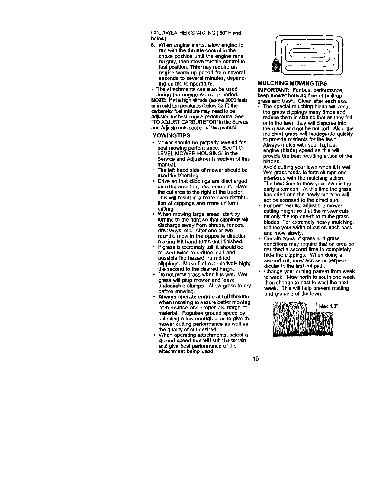
• For best results, adjust the mower
cuttingheight so that the mower cuts
off onlythe top one-thirdof the grass
blades. For extremely heavy mulching,
reduce your width of cut on each pass
and mow slowly,
• Certain types of grass and grass
conditionsmay require that an area be
mulched a second time to completely
hide the clippings. When doing a
second cut, mow across or perpen-
dicular tothe first cut path.
• Change your cutting pattern from week
to week. Mow northto southone week
then change to east to west the next
week. This will help prevent matting
and graining of the lawn.
Max 113"
ASyOUCOMPLE1E __/'i/I:_A_ _'_ _.'b '_ _,J ,, =_vjj.
Ch_ _k. O_,,,,,tior, I/ V' F
c,,_T.P,_,. I,' € r
ChecX Op_at or Presence imtl
T In_k Systar,_ _#/ J
R c,.,__ _ F,,=...,,, ,,,,' V', V' J
A s,.,p._._o.,o--,=o= V', /
._ t.b,=_,,c.,_ v' v' /
0 Ch.__ L_v_r I_, J
R C_arl B;tt_'Dry an d Tl_nlk_ls _ I_ /
Chec_ Tmns,mde Cooling I1_ [
AdjustBladeBe_s)Ten=on _s [
Adjust MOtiOnDriVeBel_s) T_mslo_ _s r
Change Engine Oil _:r_ (1_ I
E C_n _ F*lt_ I/z J
N clean Ai_ Scmo_ I_ j
G Insped M uffler/Spark Ane_ter _l_ J
J I_p_ac.OilFiler (If aquipped) f_._ J
E Clean Engine Cooling Firls _ J
ReplaceSparkPlug li/ € I
_" _-'_'_ € I
4 F_plac_ Ma_ r_ _n _ raowl_ l__r_y sol. DO rm o_ht_.
GENERAL RECOMMENDATIONS
The warranty on thistractordoes net cover
itemsthat have been subjected to operator
abuse or negligence. To receivefull value
from the warranty,operatormust maintain
tractor as insb'uctedin _is manual.
Soma adjustmentswill need to be made
pedodleally to properlymaintain your
tractor.
All adjustmentsin the Serviceand
Adjustmentssecitonof this manual should
he checked at least once each season.
• Once a year you should replacethe
spark plug,clean or replace air filter,and
check blades and beltsforwear. A new
spark plug and clean air filterassure
proper air-fuelmixture and help your
engine mn better and last longer.
BEFORE EACH USE
1. Check engine oil level.
2. Check brake operation.
3. Check tire pressure.
4. Check operator presence and
intedock systems for proper operation.
5. Check for loose fasteners.
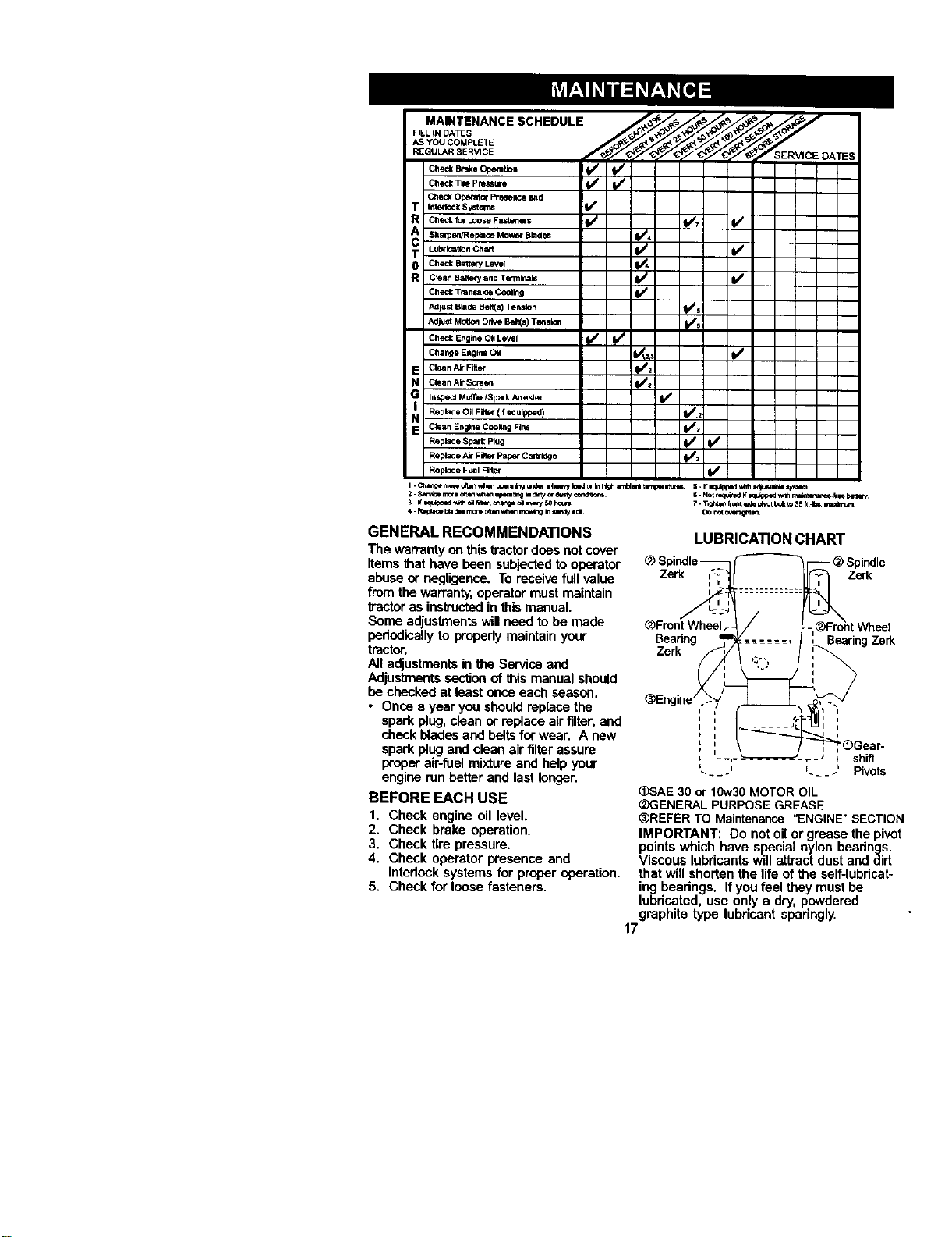
LUBRICATION CHART
Zerk Zerk
_Front Wheel
Bearing Bearing Zerk
Zerk
_)SAE 30 or 10w30MOTOR OIL
(_GENERALPURPOSEGREASE
_REFER TO Maintenance"ENGINE"SECTION
IMPORTANT: Do not oil or grease the pivot
pointswhich have special nylon bearings.
Viscous lubdcantswill attract dust and dirt
that will shorten the life of the self-lubricat-
ing bearings. Ifyou feel they must be
lubricated, use only a dry, powdered
graphite type lubricant sparingly.
17
TRACTOR
Always observe safety rules when
performing any maintenance.
BRAKE OPERATION
If tractorrequires more than six (6) feet
stoppingdistance at high speed in
highestgear, then brake must be ad-
justed. (See "TO ADJUST BRAKE" inthe
Service and Adjustments section of this
manual).
TIRES
• Maintain proper air pressure in all tires
(See "PRODUCT SPECIFICATIONS"
section of this manual).
• Keep tires free of gasoline, oil, or insect
control chemicals which can harm
rubber.
• Avoid stumps,stones, deep ruts, sharp
objects and other hazards that may
cause tire damage.
NOTE: To seal tire punctures and prevent
fiat tires due to slow leaks, tire sealant
may be purchased from your local parts
dealer. Tire sealant also prevents tire dry
rot and corrosion.
OPERATOR PRESENCE SYSTEM
Be sure operator presence and intedock
systems are workingpropedy. If your
tractor does notfunction as described,
repair the problem immediately.
• The engine should notstart unless the
clutch/brake pedal is fully depressed
and attachment clutch control is in the
disengaged position.
• When the engine is running, any
attempt by the operator to leave the
seat without first setting the parking
brake should shut off the engine.
• When the engine is running and the
attachment dutch is engaged, any
attempt by the operator to leave the
seat should shut offthe engine.
• The attachment clutchshould never
operate unless the operator is in the
seat.
BLADE CARE
For best results mower blades must be
keptsharp. Replace bent or damaged
blades.
BLADE REMOVAL
1. Raise mower to highest positionto
allow access to blades.
2. Remove hex bolt, lock washer and fiat
washer securing blade.
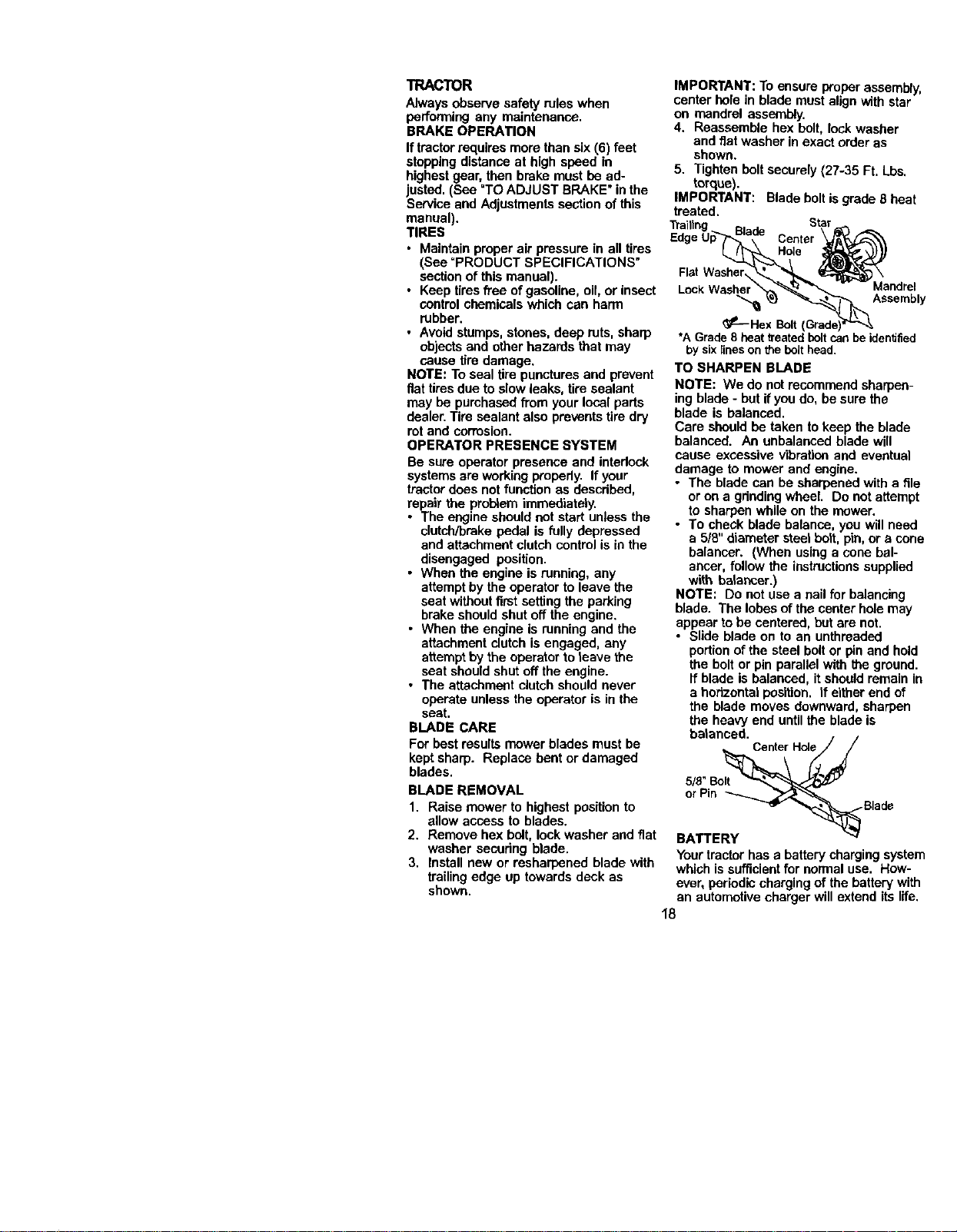
3. Install new or resharpened blade with
trailingedge up towards deck as
shown.
IMPORTANT: To ensure proper assembly,
center hole in blade must align with star
on mandrel assembly.
4. Reassemble hex bolt, lock washer
and fiat washer in exact order as
shown.
5. Tighten boltsecurely (27-35 Ft. Lbs.
torque).
IMPORTANT: Blade boltis grade 8 heat
treated.
Star
Center
Flat Washer
Mandrel
Assembly
_-- HexBolt,
*AGrade8 heatb'eatedboltcanbe identified
bysix lineson the bolthead.
TO SHARPEN BLADE
NOTE: We do not recommend sharpen-
ing blade - but if you do, be sure the
blade is balanced.
Care should be taken to keep the blade
balanced. An unbalanced blade will
cause excessive vibration and eventual
damage to mower and engine.
• The blade can be sharpened with a file
or on a gdndingwheel. Do not attempt
to sharpen while on the mower.
• To check blade balance, you will need
a 5/8" diameter steel bolt, pin, or a cone
balancer. (When using a cone bal-
ancer, follow the instructionssupplied
with balancer.)
NOTE: Do not use a nail for balancing
blade. The lobes of the center hole may
appear to be centered, but are not.
• Slide blade on to an unthreaded
portionof the steel bolt or pin and hold
the bolt or pin parallel with the ground.
If blade is balanced, it should remain in
a horizontal position, if either end of
the blade moves downward, sharpen
the heavy end untilthe blade is
balanced.
CenterHole._
5/8"Bo_
or Pin _ _"_'_._
BATTEF Y _ _Blade
Your tractorhas a batterycharging system
whioh is sufficientfor normal use. How-
ever, periodic charging of the battery with
an automotive charger will extend its life.
18
• Keep battery and terminals clean.
• Keep battery boltstight.
• Keep small vent holes open.
• Recharge at 6-10 amperes for 1 hour.
NOTE: The odginal equipment battery on
your tractor ismaintenance free. Donot
attempt to open or remove caps or covers.
Adding or checking level of electrolyte is
not necessary,
TO CLEAN BATTERY AND TERMINALS
Corrosion and dirt on the battery and
terminalscan cause the battery to "leak"
power.
1. Open batterybox door.
2, Disconnect BLACK battery cable first
then RED battery cable and remove
batteryfromtractor.
3. Rinse the battery with plain water and
dry.
4. Clean terminals and battery cable
ends with wire brush until bright.
5. Coat terminals with grease or petro-
leum jelly.
6. Reinstall battery (See =REPLACING
BATTERY" in the SERVICE AND
ADJUSTMENTS section of this
manual).
V-BELTS
Check V-belts for detedoration and wear
after 100 hours of operation and replace
ifnecessary. The beltsare notadjustable.
Replace belts if they begin to slipfrom
wear.
TRANSAXLE COOLING
Keep transaxle free from build-upof dirt
and chaff which can restrictcooling.
ENGINE
LUBRICATION
Only use high qualitydetergent oil rated
with API service classificationSF-SJ.
Select the oil's SAE viscositygrade
according to your expected operating
temperature.
TO CHANGE ENGINE OIL
Determine temperature range expected
before oilchange. All oil must meet API
service classificationSF-SJ.
• Be sure tractoris on level surface.
• Oil will drain more freely when warm.
• Catch oil in a suitable container.
1. Remove oll fillcap/dipstick. Be careful
notto allow dirt to enter the engine
when changing oil.
2. Remove cap from end of drain valve
and install the drain tube onto the
fitting.
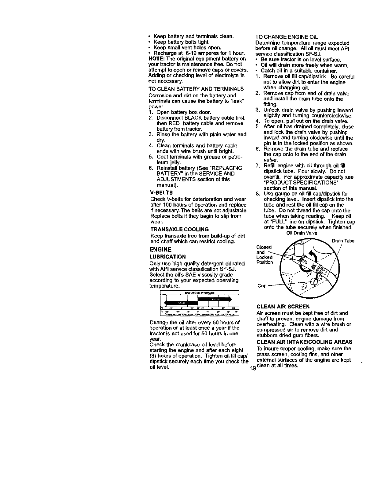
3. Unlock drain valve by pushing inward
slightly and turning counterclockwise.
4. To open, pull out on ff_edrainvalve.
5. After oil has drained completely, close
and lock the drain valve by pushing
inward and turning dockwise untilthe
[)in is in the locked positionas shown.
6, Remove the drain tube and replace
the cap onto tothe end of the drain
valve.
7. Refillengine with oil through oil fill
dipstick tube. Pour slowly. Do not
overfill. For approximate capacity see
=PRODUCT SPECIFICATIONS"
section of this manual.
8. Use gauge on oil fill cap/dipstickfor
checking level. Insert dipstick into the
tube and rest the oil fill cap on the
tube. Do not thread the cap onto the
tube when taking reading. Keep oil
at =FULL" line on dipstick. Tighten cap
onto the tube securely when finished.
Oil DrainValve
Closed _ Tube
and
Locked
posi'don
_P_T_ PJ_ GE_ATEO _?_ NEXTOL _GE
Change the oilafter every 50 hours of
operation or at least once a year if the
tractor is not used for 50 hours in one
year.
Check the crankcase oil level before
starting the engine and after each eight
(8) hours ofoperation. Tighten oil fill cap/
dipstick securely each time you check the
oil level.
CLEAN AIR SCREEN
Air screen must be keptfree of dirtand
chaff to prevent engine damage from
overheating. Clean with a wire brush or
compressed air to remove dirtand
stubborn dded gum fibers.
CLEAN AIR INTAKE/COOLING AREAS
To insure proper cooling, make sure the
grass screen, coolingfins, and other
external surfaces of the engine are kept
19dean at all times.
Every 100 beurs of operation (more often
under extremely dusty, dirty conditions),
remove the blower housing and other
coolingshrouds. Clean the cooling fins
and external surfaces as necessary.
Make sure the cooling shrouds are
reinstalled.
NOTE: Operating the engine with a
blocked grass screen, dirty or plugged
coolingfins, and/or cooling shrouds
removed will cause engine damage due
to overheating.
AIR FILTER
Your engine will not run properly using a
dirty air filter. Clean the foam pre-cleaner
after every 25 hours of operation or every
season. Service paper cartridge every
100 hours of operation or every season,
whichever occurs first.
Service air cleaner more often under
dusty conditions.
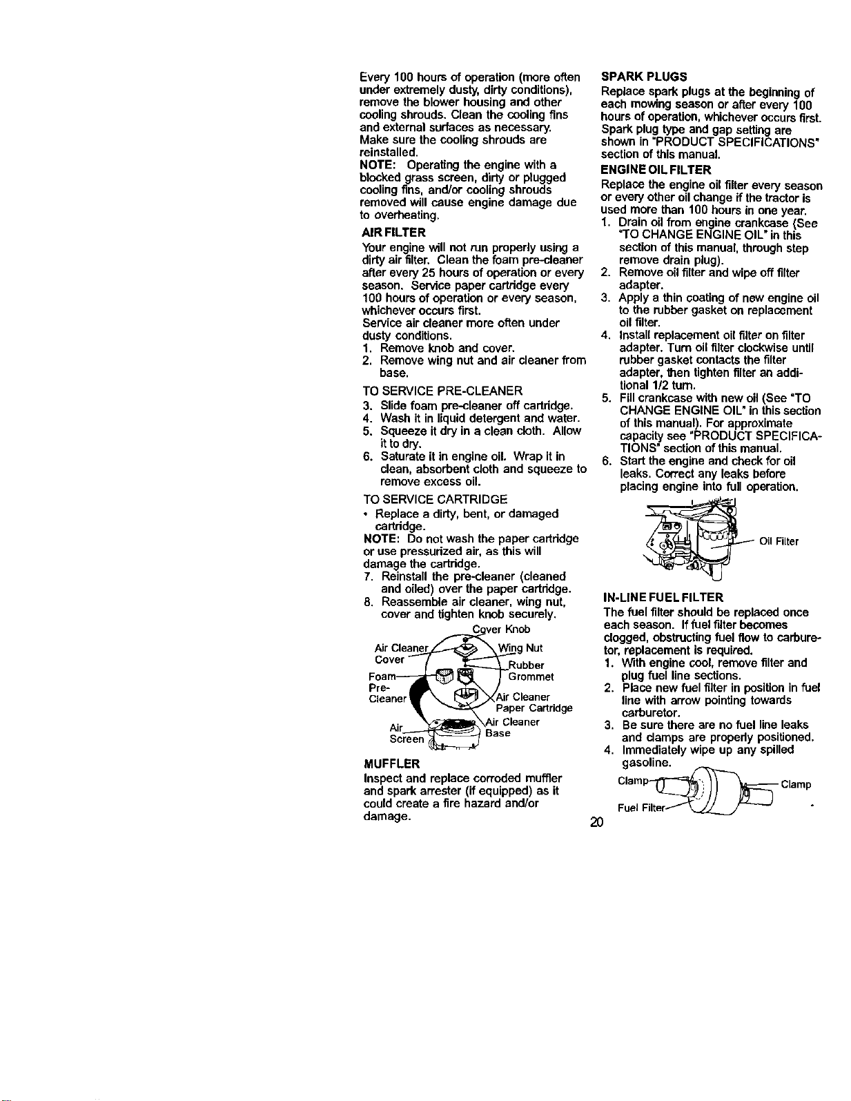
1. Remove knob and cover.
2. Remove wing nut and air cleaner from
base.
TO SERVICE PRE-CLEANER
3. Slide foam pre-cleaner off cartddge.
4. Wash it in liquid detergent and water.
5. Squeeze it dry in a clean cloth. Allow
it to dry.
6. Saturate it in engine oil. Wrap it in
clean, absorbent cloth and squeeze to
remove excess oil.
TO SERVICE CARTRIDGE
• Replace a dirty, bent, or damaged
cartridge.
NOTE: Do not wash the paper cartridge
or use pressurized air, as this will
damage the cartridga.
7. Reinstall the pre-cleaner (cleaned
and oiled) over the paper cartddge.
8. Reassemble air cleaner, wing nut,
cover and tighten knob securely.
___._ver Knob
AirCleaner___._ _._g Nut
Cover ( _ _,______r_Rubber
Foam_ _ _ Grommet
Pre- _ - ,-r_\ /
Cleaner Air Cleaner
er_ "_._pA_pCer Cartridge
A" Air Cleaner
MUFFLER
Inspect and replace corroded muffler
and spark an'ester (if equipped) as it
could create a fire hazard and/or
damage.
SPARK PLUGS
Replace spark plugs at the beginning of
each mowing season or after every 100
hours of operation, whichever occurs first.
Spark plug type and gap setting are
shown in "PRODUCT SPECIFICATIONS"
section of this manual.
ENGINE OIL FILTER
Replace the engine oil filter every season
or every other oilchange if the tractoris
used more than 100 hours in one year.
1. Drain oil from engine crankcase (See
=TOCHANGE ENGINE OIL" in this
section of this manual, throughstep
remove drain plug).
2. Remove oil filterand wipe off filter
adapter.
3. Apply a thin coating of new engine oil
to the rubber gasket on replacement
oil filter.
4. Install replacement oil filteron filter
adapter. Turn oil filter clockwise until
rubber gasket contacts the filter
adapter, _hentighten filter an addi-
tional 1/2 turn.
5. Fillcrankcase with new oil (See "TO
CHANGE ENGINE OIL"in thissection
of this manual). For approximate
capacity see "PRODUCT SPECIFICA-
TIONS" section of this manual.
6. Start the engine and check for oil
leaks. Correctany leaks before
placing engine into full operation.
OilFilter
IN-LINE FUEL FILTER
The fuel filter should be replaced once
each season. Iffuel fifier becomes
clogged, obstructingfuel flew to carbure-
tor, replacement is required.
1. With engine cool, remove filter and
plug fuel line sections.
2. Place new fuel filter in positionin fuel
line with arrow pointing towards
carburetor.
3, Be sure there are no fuel line leaks
and clamps are properly positioned.
4. Immediately wipe up any spilled
gasoline.
FC__ Clamp
20
CLEANING
i Clean engine, battery, seat, finish, etc.
of all foreign matter.
Keep finished surfaces and wheels
free of all gasoline, oil, etc,
• Protect painted surfaces with automo-
tive type wax.
We do not recommend using a garden
hose to clean your tractorunless the
electdcal system, muffler, air filterand
carburetor are covered to keep water out.
Water in engine can resultin a short-
ened engine life.
_(_ CAUTION: BEFORE PERFORMING ANY SERVICE ORADJUSTMENTS:
1. Depress clutch/brake pedal fullyand set parking brake.
2. Place gearshi_ lever in neutral (N) position.
3. Place attachment clutch in =DISENGAGED" position.
4. Turn ignitionkey "OFF" and remove key.
5. Make sure the blades and all moving parts have completely stopped.
6. Disconnect spark plug wire from spark plug and place wire where it cannot
come in contact with plug.
TRACTOR
TO REMOVE MOWER
Mower will be easier to remove from the
dght side oftractor.
1. Place attachment clutchin =DISEN-
GAGED" position.
2. Move attachment liftlever forward to
lower mower to its lowest position.
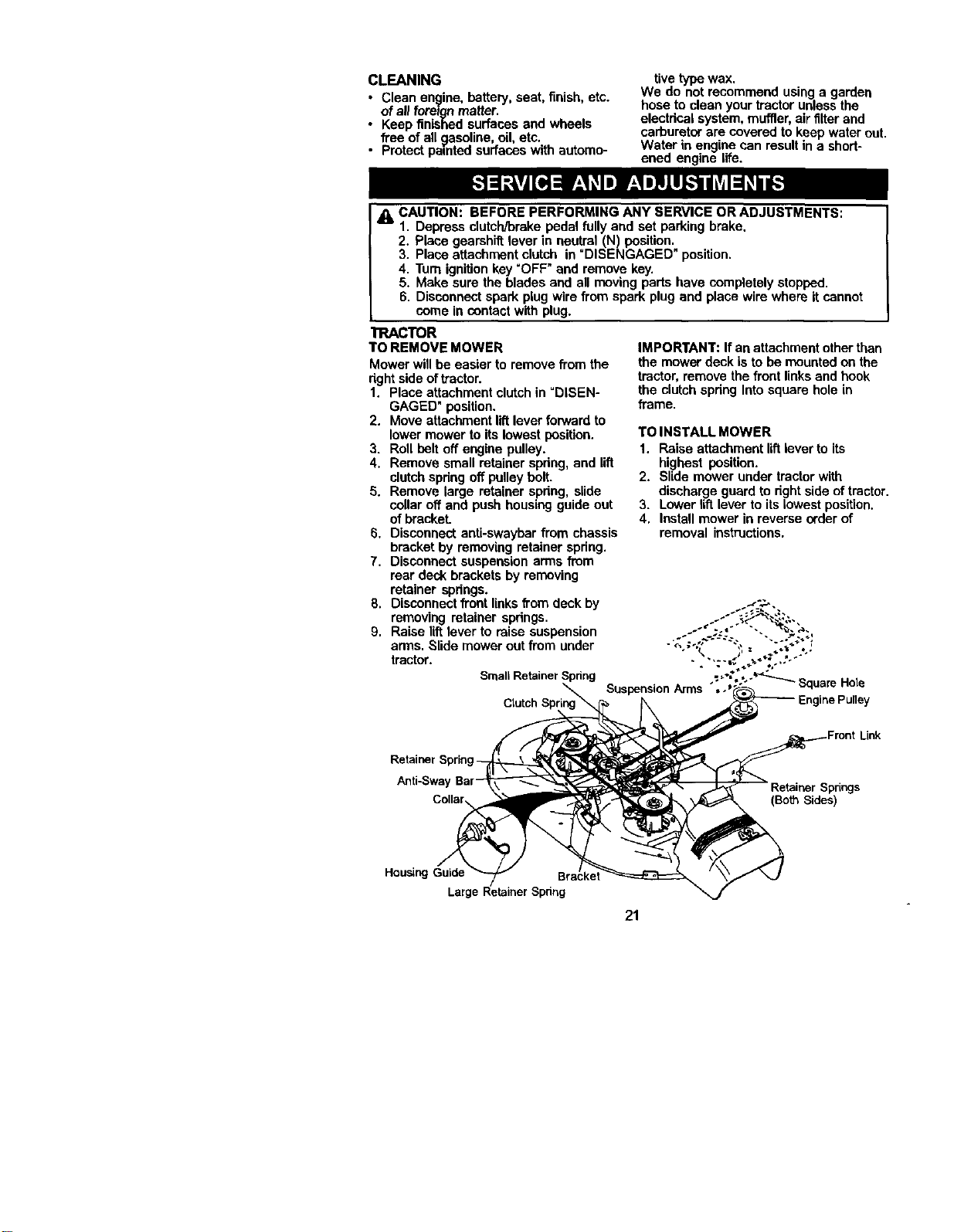
3. Roll belt off engine pulley.
4. Remove small retainer spring, and lift
clutchspdng off pulley belt.
5. Remove large retainer spdng, slide
collar off and push housing guide out
of brackeL
6. Disconnect anti-awaybar from chassis
bracket by removing retainer spdng.
7. Disconnect suspension arms from
rear deck brackets by removing
retainer spdngs.
8. Disconnect front links fromdeck by
removing retainer spdngs.
9. Raise lift lever to raise suspension
arms. Slide mower out from under
tractor.
SmallRetainerSpring
IMPORTANT: Ifan attachment other than
the mower deck is to be mounted on the
tractor,remove the front links and hook
the clutch spdng Into square hole in
frame.
TO INSTALL MOWER
1. Raise attachment liftlever to its
highest position.
2. Slide mower under tractorwith
discharge guard to dght side of tractor.
3. Lower liftlever to its lowest position.
4. Install mower in reverse erder of
removal instructions.
Hole
Clutch Sprin
Anti-Swa
(Both Sides)
Housing Guide
Larg
21
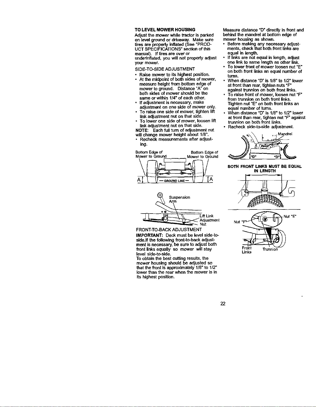
TO LEVEL MOWER HOUSING
Adjust the mower while tractor is parked
on level ground or driveway. Make sure
tires are pmpedy inflated (See "PROD-
UCT SPECIFICATIONS" sectionof this
manual). Iftires are over or
undednflatad, you will not properly adjust
your mower.
SIDE-TO-SIDE ADJUSTMENT
• Raise mower to its highest position,
• At the midpointof both sides of mower,
measure height from bottom edge of
mower to ground. Distance "A" on
both sides of mower should be the
same or within 1/4" of each other.
• Ifadjustment is necessary, make
adjustmenton one side of mower only.
• To raise one side of mower, tighten lift
linkadjustment nut on that side.
• To lower one side of mower, loosen lift
linkadjustment nut on that side.
NOTE: Each full turn of adjustment nut
will change mower height about 1/8".
• Recheck measurements after adjust-
ing.
BottomEdgeof BottomEdgeof
Mowerto Ground Mowerto Ground
\ /
Measure distance "D"directly in front and
behind the mandrel at bottom edge of
mower housing as shown.
• Before making any necessary adjust-
ments, check that both front linksare
equal in length.
• If linksare not equal in length,adjust
one link to same lengthas other link.
• To lower front of mower loosen nut"E"
on both front linksan equal number of
turns.
• When distance"O" is 1/8"to 1/2" lower
at front than rear, tightennuts=F"
against trunnion an both front links.
• To raise front of mower, loosen nut=F"
from trunnionon bothfront links.
Tighten nut=E"on beth front linksan
equal number of turns.
• When distance =D"is 1/8" to 1/2" lower
at front than rearl tightennut "F" against
trunnionon both front links.
• Recheck side-to-side adjustment.
=o ° o Ma drel
BOTH FRONT LINKS MUST BE EQUAL
IN LENGTH
Suspension
.ink
Jstrnent
lut
FRONT-TO-BACK ADJUSTMENT
IMPORTANT: Deck must be level side-to-
side.If the following front-to-backadjust-
ment is necessary, be sure to adjust both
front linksequally so mower will stay
level side-to-side.
To obtain the best cuttingresults, the
mower housing should be adjusted so
that the front is approximately 1/8" to 1/2"
lower than the rear when the mower is in
its highest position.
Nut "F_NUt "E"
Links
22
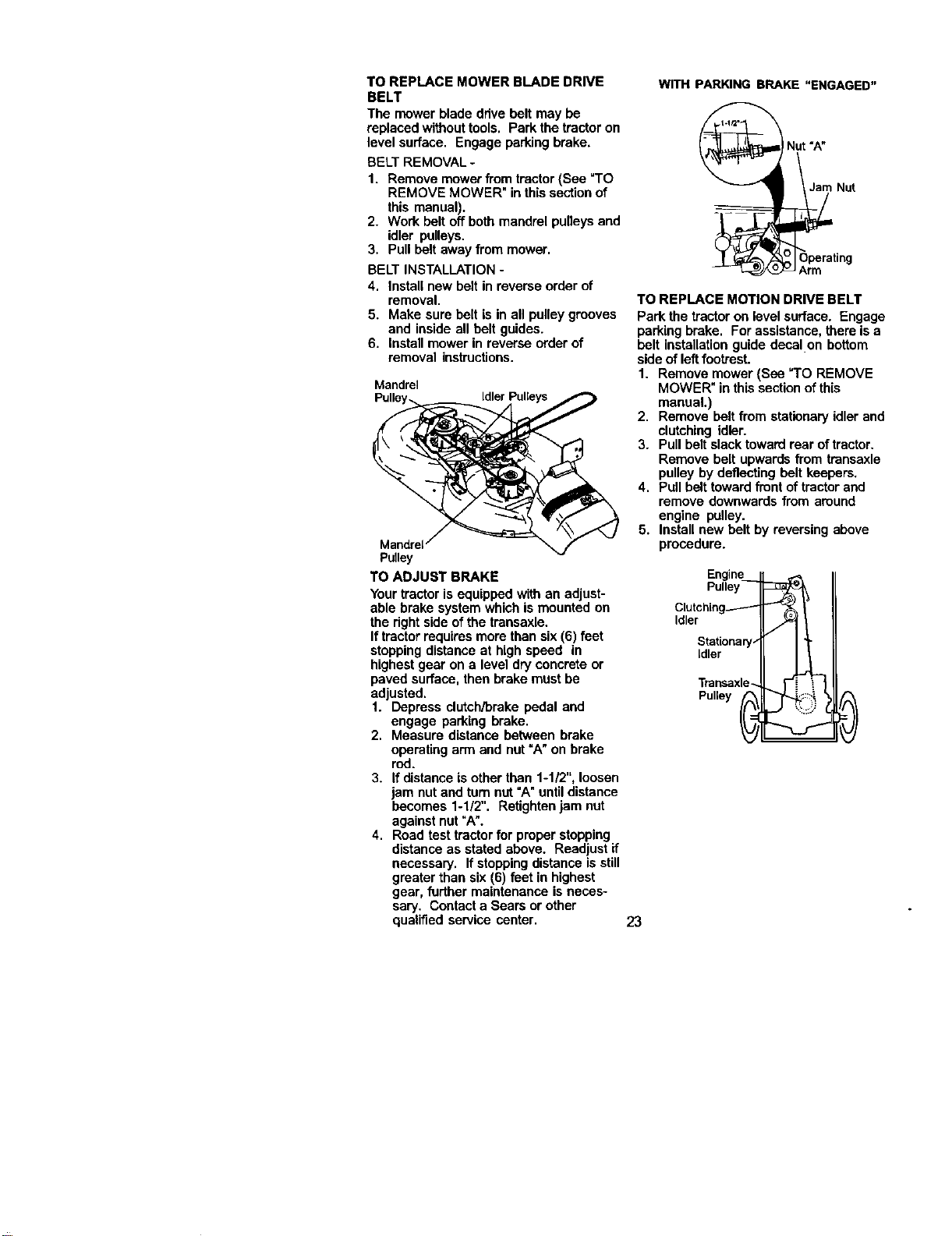
TO REPLACE MOWER BLADE DRIVE
BELT
The mower blade drive bolt may be
replaced withouttools. Park the tractor on
level surface. Engage parkingbrake,
BELT REMOVAL -
1. Remove mower from tractor (See "TO
REMOVE MOWER" in this section of
this manual).
2. Work bolt off both mandrel pulleys and
idler pulleys.
3. Pull bolt away from mower.
BELT INSTALLATION -
4, Install new belt in reverse order of
removal.
5. Make sure belt is in all pulley grooves
and inside all bolt guides.
6. Install mower in reverse order of
removal instructions.
Mandrel
Pulley
TO ADJUST BRAKE
Your tractor is equipped with an adjust-
able brake system whichis mounted on
the rightside of the transaxle.
If tractorrequires more than six (6) feet
stopping distanceat high speed in
highest gear on a level dry concrete or
paved surface, then brake must be
adjusted.
1. Depress clutch/brake pedal and
engage parking brake.
2. Measure distance between brake
operating arm and nut "A" on brake
red.
3. If distance is other than 1-1/2",loosen
jam nutand tum nut "A" untildistance
becomes 1-1/2". Retightee jam nut
against nut "A".
4. Road test tractor for proper stopping
distance as stated above. Readjust if
necessary. If stoppingdistance isstill
greater than six (6) feet in highest
gear, further maintenance is neces-
sary. Contact a Sears or other
qualified service center.
WITH PARKING BRAKE "ENGAGED"
Jam Nut
A_rn
TO REPLACE MOTION DRIVE BELT
Park the tractor on level surface. Engage
parking brake. For assistance, there is a
belt installationguide decal on bottom
side of left footrest.
1. Remove mower (See "TO REMOVE
MOWER" in this sectionof this
manual.)
2. Remove bolt from stationary idler and
clutching idler.
3. Pull belt slack toward rear of trsctor.
Remove belt upwards from transaxle
pulley by deflecting bolt keepers,
4. Pull belt toward front of tractorand
remove downwards from around
engine pulley.
5. Install new belt by reversing above
procedure.
Engine___
Pulley
Clutching------"-
Idler
Stationary-"
Idler
Transaxle_ '_
Pulley _ _ ._
23
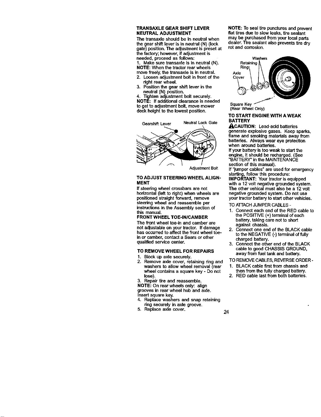
TRANSAXLE GEAR SHIFT LEVER
NEUTRAL ADJUSTMENT
The transaxle should be in neutral when
the gear shiftlever is in neutral (N) (lock
gate) position. The adjustment is preset at
the factory; however, if adjustment is
needed, proceed as follows:
1. Make sure transaxle is in neutral (N).
NOTE: When the tractorrear wheels
move freely, the transaxle is in neutral.
2. Loosenadjustment bolt in front of the
dght rear wheel.
3. Position the gear shift lever in the
neutral (N) position.
4. Tighten adjustment bolt securely.
NOTE: If additional clearance is needed
to get to adjustment bolt, move mower
deck height to the lowest position.
Gearshift Lever Neutral Lock Gate
Adjustment Bolt
TO ADJUST STEERING WHEEL ALIGN-
MENT
If steering wheel crossbars are not
hodzontal (left to dght) when wheels are
positionedstraight forward, remove
steedng wheel and reassemble per
instructionsin the Assembly section of
this manual,
FRONT WHEEL TOE-IN/CAM BER
The front wheel toe-in and camber are
not adjustableon your tractor. If damage
has occurred to affect the front wheel toe-
in or camber, contact a Sears or other
qualified service center.
TO REMOVE WHEEL FOR REPAIRS
1. Block up axle securely.
2. Remove axle cover, retaining ring and
washers to allow wheel removal (rear
wheel contains a square key - Do not
lose).
3. Repair tire and reassemble.
NOTE: On rear wheels only: align
grooves in rear wheel hub and axle.
Insertsquare key.
4. Replace washers and snap retaining
deg securely in axle groove.
5. Replace axle cover,
24
NOTE: To seal tire puncturesand prevent
fiat tires due to slow leaks, tire sealant
may he purchased from your local parts
dealer. Tire sealant also prevents tiredry
rot and corrosion.
Washers
Retaining_
Ring
Axle
SquareKey _
{Rear WheelOnly)
TO START ENGINE WITH A WEAK
BATTERY
,_CAUTION: Lead-acid batteries
generate explosive gases. Keep sparks,
flame and smoking materials away from
battedes. Always wear eye protection
when around battades.
If yourbatteryis too weak to start the
engine, it should he recharged. (See
"BATTERY" in the MAINTENANCE
section of this manual).
If "jumper cables" are used for emergency
starting,follow this procedure:
IMPORTANT: Your tractorisequipped
with a 12 volt negative grounded system.
The other vehical must also he a 12 volt
negative grounded system. Do not use
your tractor batteryto start other vehicles.
TO ATTACHJUMPER CABLES -
1. Connect each and of the RED cable to
the POSITIVE (+) terminal of each
battery, taking care not to short
against chassis.
2. Connect one end of the BLACK cable
to the NEGATIVE (-) terminal of fully
charged battery.
3. Connect the other end of the BLACK
cable to good CHASSIS GROUND,
away from fuel tank and battery.
TO REMOVE CABLES, REVERSE ORDER-
1. BLACK cable first from chassis and
then from the fully charged battery.
2. RED cable last from both battedes.
positive Terminal Negative Terminal Hex
Nut Bolt
Battery
PositiveTerminal
Negative Terminal
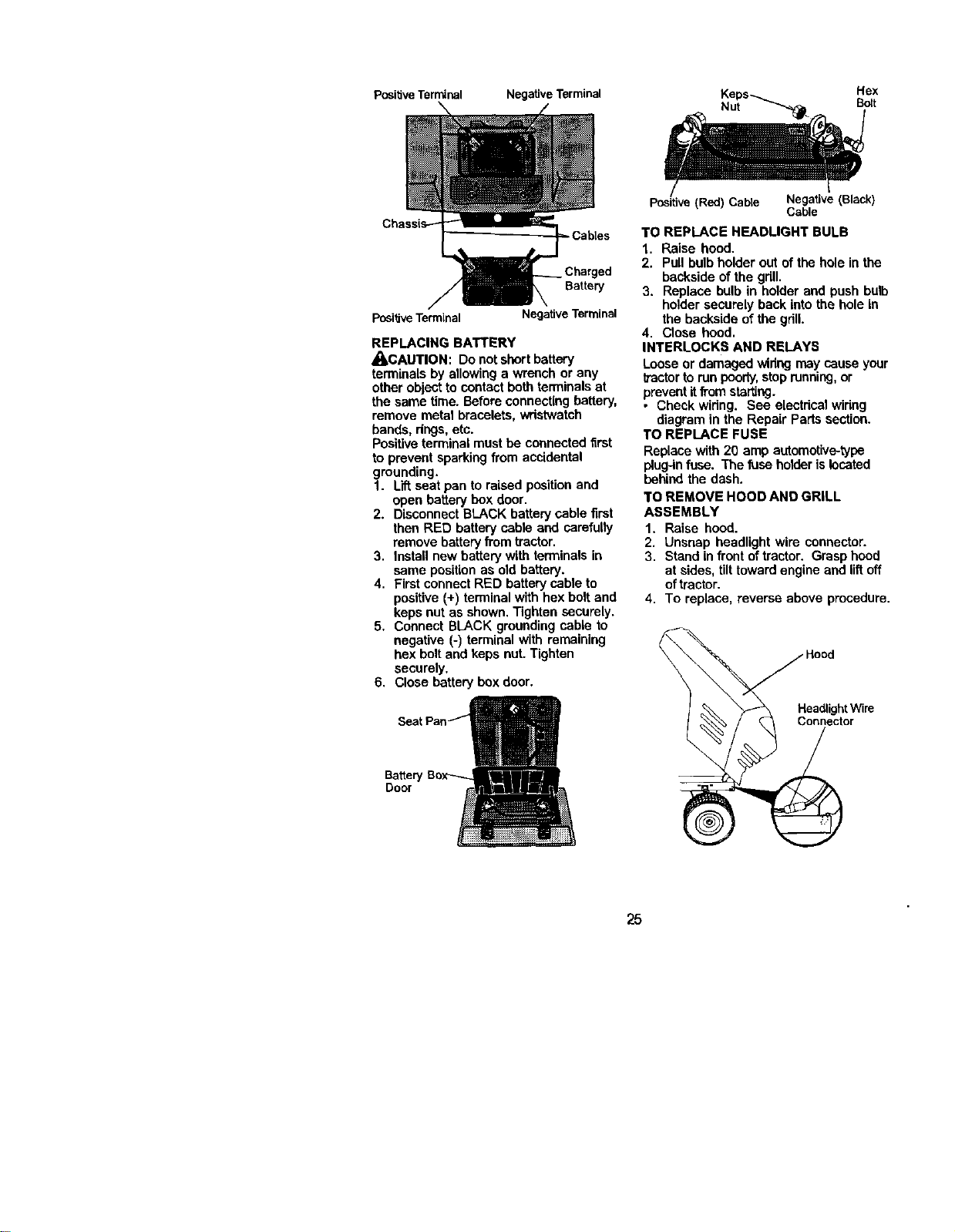
REPLACING BATTERY
_CAUTION: Do not short battery
terminals by allowing a wrench or any
other object to contact bothterminals at
the same time. Before connecting battery,
remove metal bracelets, wristwatch
bands, rings,etc.
Positiveterminal must be connected first
to prevent sparking from accidental
grounding.
1. Lift seat pan to raised positionand
open battery box door,
2. Disconnect BLACK battery cable first
then RED battery cable end carefully
remove batteryfrom tractor.
3. Install new batterywith terminals in
same positionas old battery.
4. First connectRED batterysable to
positive (+) terminal with hex bolt and
keps nut as shown.Tighten securely.
5. Connect BLACK grounding cable to
negative (-) terminal with remaining
hex boltand keps nut. Tighten
securely.
6. Close battery box door.
Batter
Door
(Red) Cable Negative (Black)
Cable
TO REPLACE HEADLIGHT BULB
1. Raise hood.
2. Pull bulb holder out of the hole in the
backside of the gdll.
3. Replace bulb in holder and push bulb
holder securely back intothe hole in
the backside of the gdlL
4. Close hood.
INTERLOCKS AND RELAYS
Looseor damaged widag may cause your
lractortorun poorly,stop running,or
preventitfrom sta_ng.
• Check wiring. See electdcal widng
diagram in the Repair Parts section.
TO REPLACE FUSE
Replace with 20 amp automotive-type
plug-infuse. The fuse holder islocated
behind the dash.
TO REMOVE HOOD AND GRILL
ASSEMBLY
1. Raise hood.
2. Unsnap headlight wire connector.
3. Stand in front oftractor. Grasp hood
at sides, tilttoward engine and liftoff
oftractor.
4. To replace, reverse above procedure.
25
ENGINE
Maintenance, repair, or replacement of
the emission control devices and sys-
tems, which are being done at the
customers expense, may be performed
by any non-road engine repair establish-
ment or individual.Warranty repairs must
be performed by an authorized engine
manufacturer'seawice outlet.
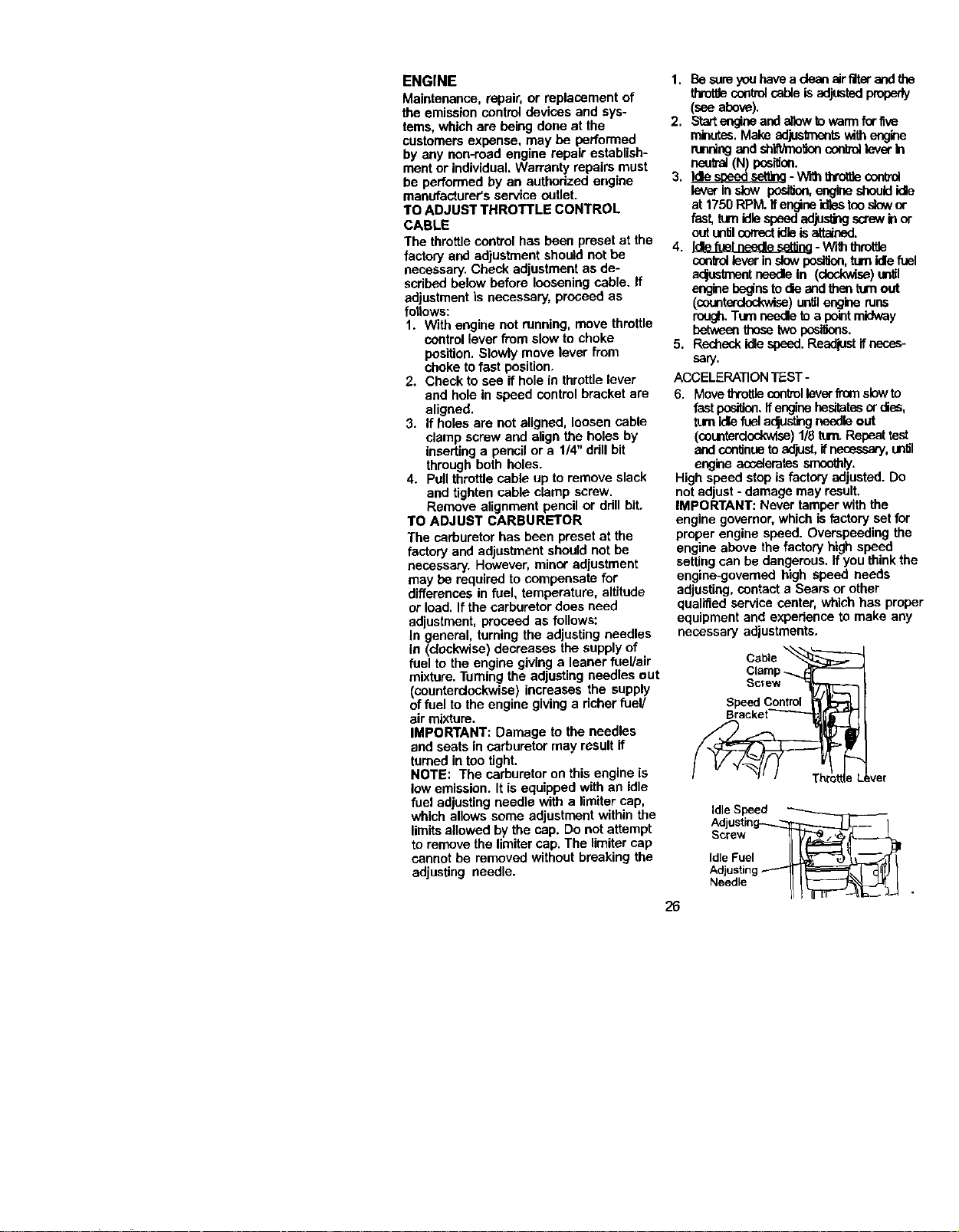
TO ADJUST THROTTLE CONTROL
CABLE
The throttlecontrol has been preset at the
factory and adjustment should not be
necessary. Check adjustment as de-
scribed below before loosening cable. If
adjustment is necessary, proceed as
fotiows:
1. With engine not running, move throttle
control lever from slow to choke
position. Slowly move lever from
choke to fast position,
2. Check to see if hole in throttle lever
and hole in speed control bracket are
aligned.
3. If holes are not aligned, loosen cable
clamp screw and alignthe holes by
inserting a pencil or a 1/4" drillbit
through both holes.
4. Pull throttlecable up to remove slack
and tighten cable clamp screw.
Remove alignment pencil or drillbit,
TO ADJUST CARBURETOR
The carburetor has been preset at the
factory and adjustment should not be
necessary. However, minor adjustment
may be required to compensate for
differences in fuel, temperature, altitude
or load. If the carburetor does need
adjustment, proceed as follows:
In general, turning the adjusting needles
in (dockwise) decreases the supply of
fuel tothe engine giving a leaner fuel/air
mixture.Turning the adjusting needles out
(counterclockwise) increases the supply
offuel to the engine givinga richer fuel/
air mixture.
IMPORTANT: Damage to the needles
and seats in carburetor may result if
turned in tootight.
NOTE: The carburetor on this engine is
low emission. It is equipped with an idle
fuel adjustingneedle with a limiter cap,
which allows some adjustment within the
limitsallowed by the cap. Do not attempt
to remove the limitercap. The limiter cap
cannot be removed without breaking the
adjusting needle.
26
1. Be sureyouhavea dean airfilterandthe
throttlecontrolcable isadjustedproperly
(see above).
2. Startengtheand allewto warmfor five
minutes.Make acrjuslmentswithengine
runningand sh_lten conb'o_leverIn
neutral(N) position.
3. Idlesl_d ssttina -"W_ththrotaecontrol
leverin stow posilien,enginesbeuididle
at 1750 RPM. Ifengineidlestooslowor
fust, tam idlespeedadjustingscrewinor
outunf_lcorrectidleisattained.
4. Idlefuel needlesettina-WiththmttJe
ccoifd lever inslowpesilion, turnidlefuel
acjustmentneedleIn (clockwise)until
enginebeginsto d'=eandthenturnout
(counterclockwise) untilengineruns
rough. Turnneedleto a pointmidway
betweenthose twopesi_ons.
5. Recheckidlespeed. Readjustif neces-
sary.
ACCELERATIONTEST -
6. Movethrottlecontrolleverfrom slowto
fastpeail_. Ifenginehesitatesor dies,
turnidlefuelaclustingneedleout
(counterdGd_dse)1/8turn.Repeattest
and continueto adjust,ifnecessary,un_l
engineaccelerates smoothly.
Highspeed stopis factory adjusted. Do
notadjust- damage may result.
IMPORTANT: Never tamper with the
engine governor,which is factory set for
proper engine speed. Overspeeding the
engine above the factory high speed
setting can be dangerous. If youthinkthe
engine-govemed high speed needs
adjusting,contact a Sears or other
qualified service center, which has proper
equipment and experience to make any
necessary adjustments.
Cable
Clamp -_
Screw
Speed Control
IdleSpeed
Adjustin_
Screw
IdleFuel
Needle
Immediatelyprepareyourtractor for
storage at the end of the season or if the
tractor will not be usedfor 30 days or
ore.
_,CAUTION: Never store the tractorwith
gasoline in the tank inside a building
where fumes may reach an open flame or
spark. Allow the engine to cool before
stodng in any enclosure.
TRACTOR
Remove mower from tractor for winter
storage. When mower is to be stored for
a period of time, clean itthoroughly,
remove all dirt,grease, leaves, etc. Store
in a clean, dry area.
1. Clean entire tractor (See "CLEANING"
in the Maintenance section of this
manual).
2. Inspect and replace belts, if necessary
(See belt replacement instructionsin
the Service and Adjustmentssection
of this manual).
3. Lubdcete as shown in the Mainte-
nance section of this manual.
4. Be sure that all nuts, bolts and screws
are securely fastened. Inspect moving
parts for damage, breakage and wear.
Replace if necessary.
5. Touch up all rusted or chipped paint
surfaces; sand lightlybefore painting.
BA'rrERY
• Fully charge the battery for storage.
• After a pedod of time in storage, battery
may require recharging.
• To help prevent corrosionand power
leakage dudng long periods of storage,
battery cables should be disconnected
and battery cleaned thoroughly (see
"TO CLEAN BATTERY AND TERMI-
NALS" in the Maintenance section of
this manual).
• After cleaning, leave cables discon-
nected and place cables where they
cannot come in contact with battery
terminals.
• If battery isremoved from tractorfor
storage, do not store batterydirectly on
concrete or damp surfaces.
ENGINE
FUEL SYSTEM
IMPORTANT: Itis importantto prevent
gum depositesfrom forming in essential
fuel system parts such as carburetor,fuel
hose, or tank dudng storage. Also,
expedance indicates that alcohol
blended fuels (called gasobol or using
ethanol or methanol) can attract moisture
which leads to separation and formation
of acids dudng storage. Acidic gas can
damage the fuel system of and engine
while in storage.
1. Drain the fuel tank.
2. Start the engine and let it run untilthe
fuel lines and carburetor are empty.
• Never use engine or carburetorcleaner
products in the fuel tank or permanent
damage may occur.
• Use fresh fuel next season.
NOTE: Fuel stabilizer is an acceptable
alternative in minimizingthe formation of
fuel gum deposits dudng storage. Add
stabilizer to gasoline in fuel tank or
storage container. Alwaysfollow the mix
ratio found on stabilizercontainer. Run
engine at least 10 minutesafter adding
stabilizer to allow the stabilizer to reach
the carburetor. Do not drain the gas tank
and carburetor if usingfuel stabilizer.
ENGINE OIL
Drain oil (with engine warm) and replace
with clean engine oil. (See "ENGINE" in
the Maintenance section of this manual).
CYLINDER(S)
1. Remove spark plug(s).
2. Pour one ounce ofoil through spark
plug hole(s) into cylinder(s).
3. Turn ignitionkey to "START" position
for a few secondsto distributeoil.
4. Replace with new spark plug(s).
OTHER
• Do not store gasoline from one season
to another.
• Replace your gasoline can if your can
startsto rust. Rust and/or dirt inyour
gasoline will cause problems.
• If possible,store your tractor indoors
and cover it to give protectionfrom dust
and dirt.
• Cover your tractor with a suitable
protective cover thatdoes not retain
moisture. Do not use plastic. Plastic
cannot breathe which allows conden-
sationto form and will cause your
tractor to rust.
IMPORTANT: Never cover tractorwhile
engine and exhaust areas are stillwarm.
27
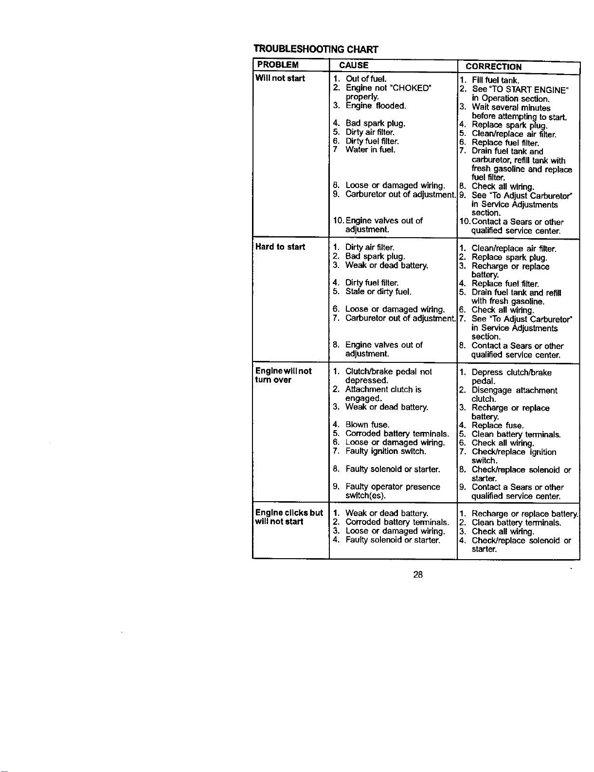
TROUBLESHOOTINGCHART
PROBLEM CAUSE CORRECTION
Will not start
Hard to start
Englnewlllnot
turn over
Engine clicks but
will not start
1. Out of fuel.
2. Engine not =CHOKED"
properly.
3. Engine flooded.
4. Bad spark plug.
5, Dirty air filter,
6. Dirty fuel filter.
7 Water in fuel.
8. Loose or damaged wiring.
9. Carburetor out of adjustment
10.Engine valves out of
adjustment.
1. Dirty airfilter.
2. Bad spark plug.
3. Weak or dead battery.
4. Dirty fuelfilter.
5. Stale or dirtyfuel.
6. Loose or damaged wiring.
7. Carburetor out of adjustment.
8. Engine valves out of
adjustment.
1. Clutch/brake pedal not
depressed.
2. Attachment clutch is
engaged.
3. Weak or dead battery,
4. Blown fuse.
5. Corroded battery terminals.
6. Loose or damaged wiring.
7. Faulty ignition switch.
8. Faulty solenoidor starter.
9. Faulty operator presence
switch[es).
1. Weak or dead battery.
2. Corroded battery terminals.
3. Loose or damaged wiring.
4. Faultysolenoid or starter.
1. Fill fuel tank.
2. See "TO START ENGINE"
in Operation section.
3. Wait several minutes
before attempting to start.
4. Replace spark plug.
5, Claan/replece air filter.
6, Replace fuel filter.
7. Drain fuel tank and
carburetor, refilltank with
fresh gasoline and replaca
fuel filter.
8. Check all widng,
9. See =ToAdjust Carburetor"
in Service Adjustments
section.
10.Contact a Sears or other
qualified service center.
1. Clean/replace air filter.
2. Replace spark plug.
3. Recharge or replace
battery.
4. Replace fuel filter.
5. Drain fuel tank and refill
with fresh gasoline.
6. Check all widng.
7. See =ToAdjust Carburetor"
in Service Adjustments
section.
8. Contact a Sears or other
qualified service center.
1. Depress clutch/brake
pedal.
2. Disengage attachment
clutch.
3. Recharge or replace
battery.
4. Replace fuse.
5. Clean battery terminals.
6. Check all widng.
7, Check/replace ignition
switch,
B. Check/replace solenoid or
starter.
_). Contact a Sears or other
qualified service center.
1. Recharge or replace batter
2. Clean battery terminals.
3. Check all wiring.
4. Check/replace solenoid or
starter.
28
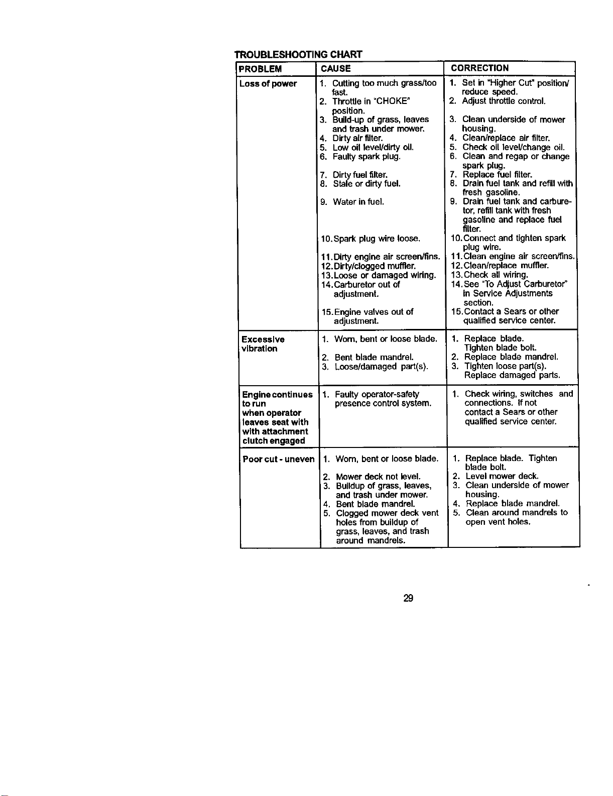
TROUBLESHOOTING CHART
PROBLEM CAUSE
Loss of power 1. Cuttingtoo much grass/too
Excessive
vibration
Engine continues
to run
when operator
leaves seat with
with attachment
clutch engaged
Poorcut-uneven
fast.
2. Throttle in "CHOKE"
position.
3. Build-up of grass, leaves
and trash under mower.
4. Dirty air filter.
5. Low oil level/dirty oil,
6. Faulty spark plug.
7. Dirty fuel filter.
8. Stale or dirtyfuel.
9. Water in fuel.
10.Spark plug wire loose.
11.Dirty engine air scraen/fins.
12.Dirty/clogged muffler.
! 13.Loose or damaged widng.
14. Carburetorout of
adjustment.
15. Engine valves out of
adjustment.
1. Worn, bent or loose blade.
2. Bent blade mandrel.
3. Loose/damaged part(s).
1. Faulty operator-safety
presence controlsystem.
1. Wom, bent or loose blade.
2. Mower deck not level.
3. Buildupof grass, leaves,
and trash under mower.
4. Bent blade mandrel.
5. Clogged mower deck vent
holes from buildup of
grass, leaves, and trash
around mandrels.
CORRECTION
1. Set in "Higher Cut" position/
reduce speed.
2. Adjust throttlecontml.
3. Clean underside of mower
housing.
4. Clean/raplace air filter.
5. Check oil level/change oil.
6. Clean and regap or change
spark plug.
7, Replace fuel filter.
8. Drain fuel tank and refillwith
fresh gasoline.
9. Drain fuel tank and carbure-
tor,refilltankwith fresh
gasoline and replace fuel
filter.
10.Connect and tighten spark
plug wire.
11.Clean engine air scraen/fms.
12.Clean/replace muffler.
13.Check all widng.
14. See "To Adjust Carburetor'
in Service Adjustments
section.
15.Contact a Sears or other
qualified service center.
1. Replace blade.
Tighten blade bolt.
2. Replace blade mandrel.
3. Tighten loose part(s).
Replace damaged parts.
1. Check wiring, switches and
connections. If not
contact a Sears or other
qualified service center.
1. Replace blade. Tighten
blade bolt.
2. Level mower deck.
3. Clean underside of mower
housing.
4, Replace blade mandrel.
5. Clean around mandrels to
open vent holes.
29
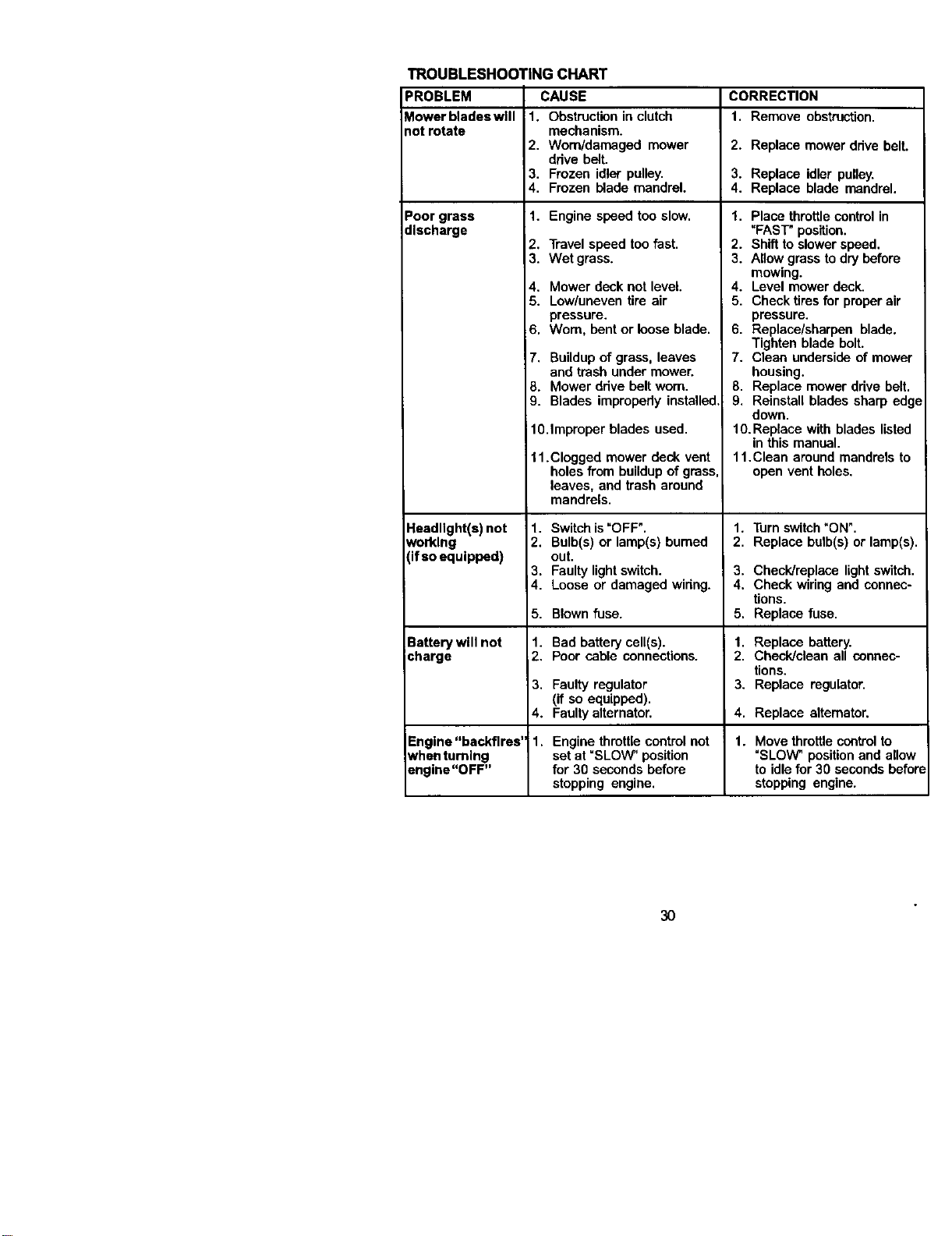
TROUBLESHOOTING CHART
PROBLEM CAUSE CORRECTION
Mowerbladeswlll 1. Obstruction in clutch 1, Remove obstruction,
1orrotate mechanism.
2, Worn/damaged mower 2. Replace mower dave belt.
drive belt.
3, Frozen idler pulley, 3. Replace idler pulley.
4, Frozen blade mandrel. 4. Replace blade mandrel.
Poor grass 1. Engine speed too slow,
discharge
Headlight(s) not
working
(if so equipped)
2. Travel speed too fast.
3. Wet grass.
4, Mower deck not level.
5. Low/uneven tire air
pressure.
6. Worn, bent or loose blade.
7. Buildupof grass, leaves
and trash under mower.
8. Mower drive belt worn.
9. Blades impropedy installed,
10.Improper blades used.
11.Clogged mower deck vent
holes from buildupof grass,
leaves, and trash around
mandrels.
1. Switch is"OFF".
2. Bulb(s) or lamp(s) bumed
out.
3. Faulty light switch.
4. Loose or damaged widng.
5.
Battery will not 1.
¢harge 2,
3.
4.
Engine "backfires" 1.
whenturning
engine"OFF"
Blown fuse.
Bad battery cell(s).
Poor cable connections.
1. Place throttlecontrol in
"FAST" position.
2. Shift to slower speed.
3. Allow grass to dry before
mowing.
4. Level mower deck.
5, Check tiresfor proper air
pressure,
6, Replace/sharpen blade.
Tighten blade bolt.
7, Clean underside of mower
housing.
8, Replace mower drive belt.
9, Reinstall blades sharp edge
down,
10. Replace with blades listed
in this manual.
11.Clean around mandrels to
open vent holes.
1. Turnswitch"ON".
2. Replace bulb(s) or lamp(s).
3. Check/replece light switch.
4. Check wiring and connec-
tions.
5, Replace fuse,
1. Replace battery.
2. Check/clean all connec-
tions.
3. Replace regulator,Faulty regulator
(if so equipped).
Faulty alternator. 4. Replace alternator.
Engine throttlecontrol not 1. Move throttlecontrolto
set at "SLOW" position "SLOW" positionand allow
for 30 seconds before to idle for 30 secondsbefon
stopping engine, stopping engine.
3O
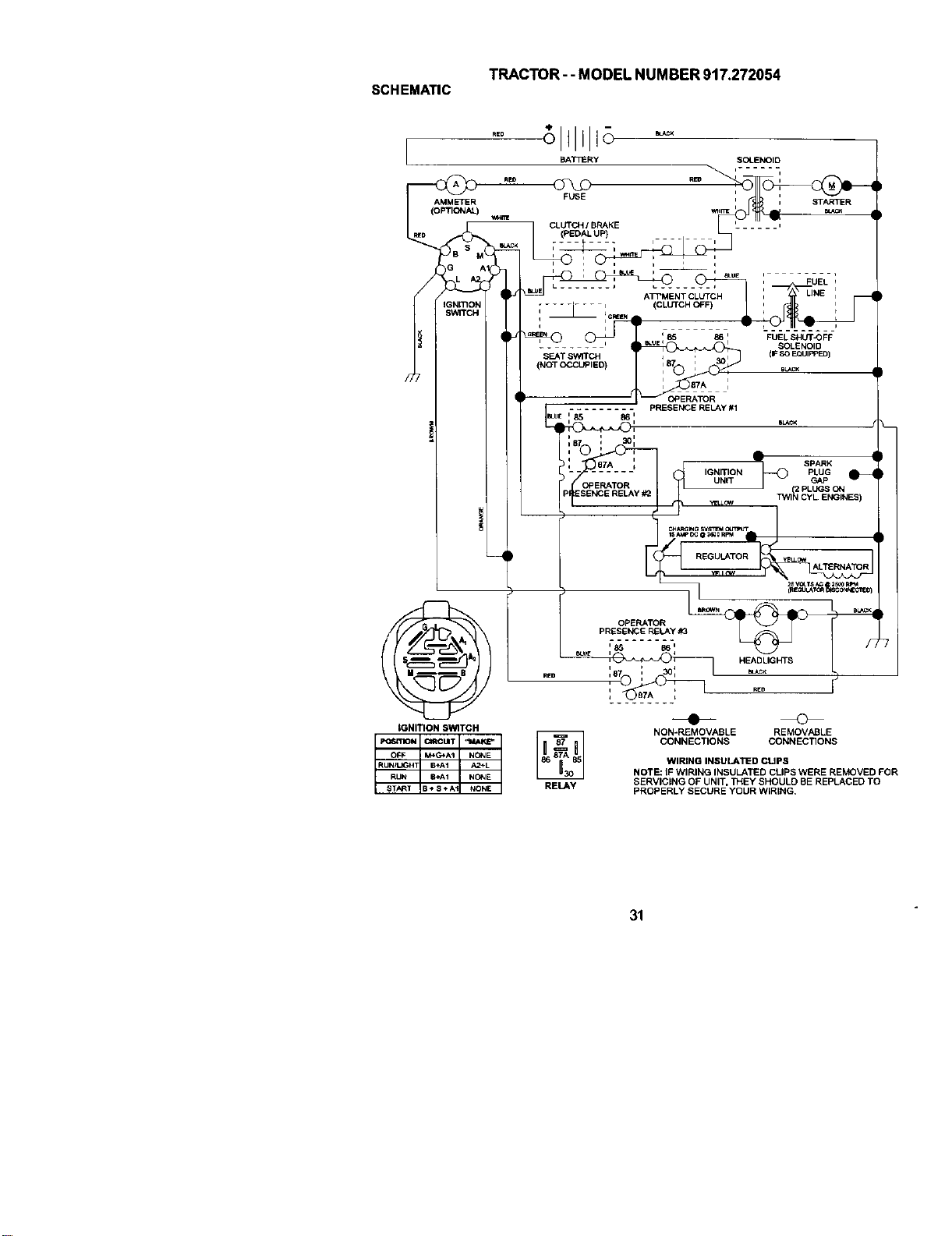
SCHEMATIC
T_C_R- - MODEL NUMBER 917.272054
RBD
i
AMM_ER
(O_)
iGNITION SWITCH
_T_Ry SOLENOID
_ ,
F_E , _R
CL_ I B_KE
(PEDAL UP) ,...... ,
UNE ,
i i
....... i (CLUTCH C_F)
q IGREIN_i,
_I_.EN q85 86 I FUEL SHUTOFF
SOI-ENOID
S_T SW_ I i , _^ (F SOEQUIP]
87A
PRESE_E RElY #1
:87 : _:
,©_ - ,
:_22:o::I 4 ,ON.,ONG-O°:x:_1
w_v _ CYL E_INES)
YEU'°WALTERNATOR
-- _ 2B V(XTS AC 3£_J RPM
OPE_TOR
PRESE_E _Y
,-_..... 18-, /,
e_o __ _e i _ H_DLIG_S
RELAY
NON-REMOVABLE REMOVABLE
CONNECTIONS CONNECTIONS
WIRING INSULA_D CUPS
NOT_ IF WIRING INSUreD CLIPS WERE RE_VED FOR
SERVICING OF UNIT, _EY SHOULD BE REP_CED TO
PROPERLY SECURE YOUR WIRING,
31
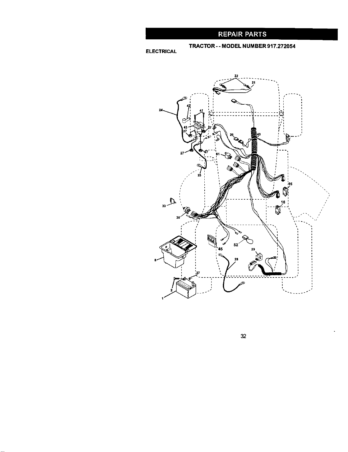
TRACTOR-- MODEL NUMBER 917.272054
ELECTRICAL
i t
i
t
-~ .... .
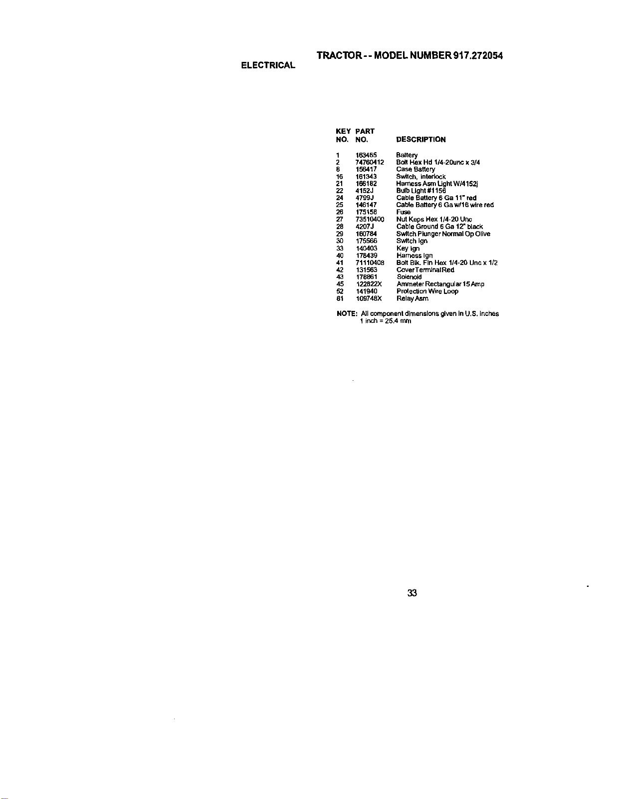
TRACTOR-- MODEL NUMBER 917.272054
ELECTRICAL
KEY pART
NO. NO, DESCRIPTION
1 163465 Battery
2 74760412 Bolt Hex Hd ll4-2Ounc x 3/4
8 156417 Case Battery
16 161343 Switch, interlOCk
21 166162 Harness Asm tJght WI4152j
22 4152J Bulb Ught #1156
24 4799J CabLeBattery 6 Ga 11" red
25 146147 Cable Battery 6 Ga w116wire red
26 175158 FUSe
27 73510400 Nut Keps Hex 114-20 Uric
28 4207J Cabte Ground 6 Ga 12" black
29 160784 Switch Plunger Normal Op Olive
30 175566 Switch Ign
33 140403 Key Ign
40 178439 Harr_ss Ign
41 71110408 Bolt BLk.Fin Hex 114-20 Unc x 1/2
42 131563 CoverTermlr_lRed
43 178861 Solenoid
45 122822X Ammeter Rectangular 15 Amp
52 141940 Protection W_reLoop
81 109748X RelayAsm
NOTE: All component dimensions given In U.S. inches
1 inch = 25A mm
33
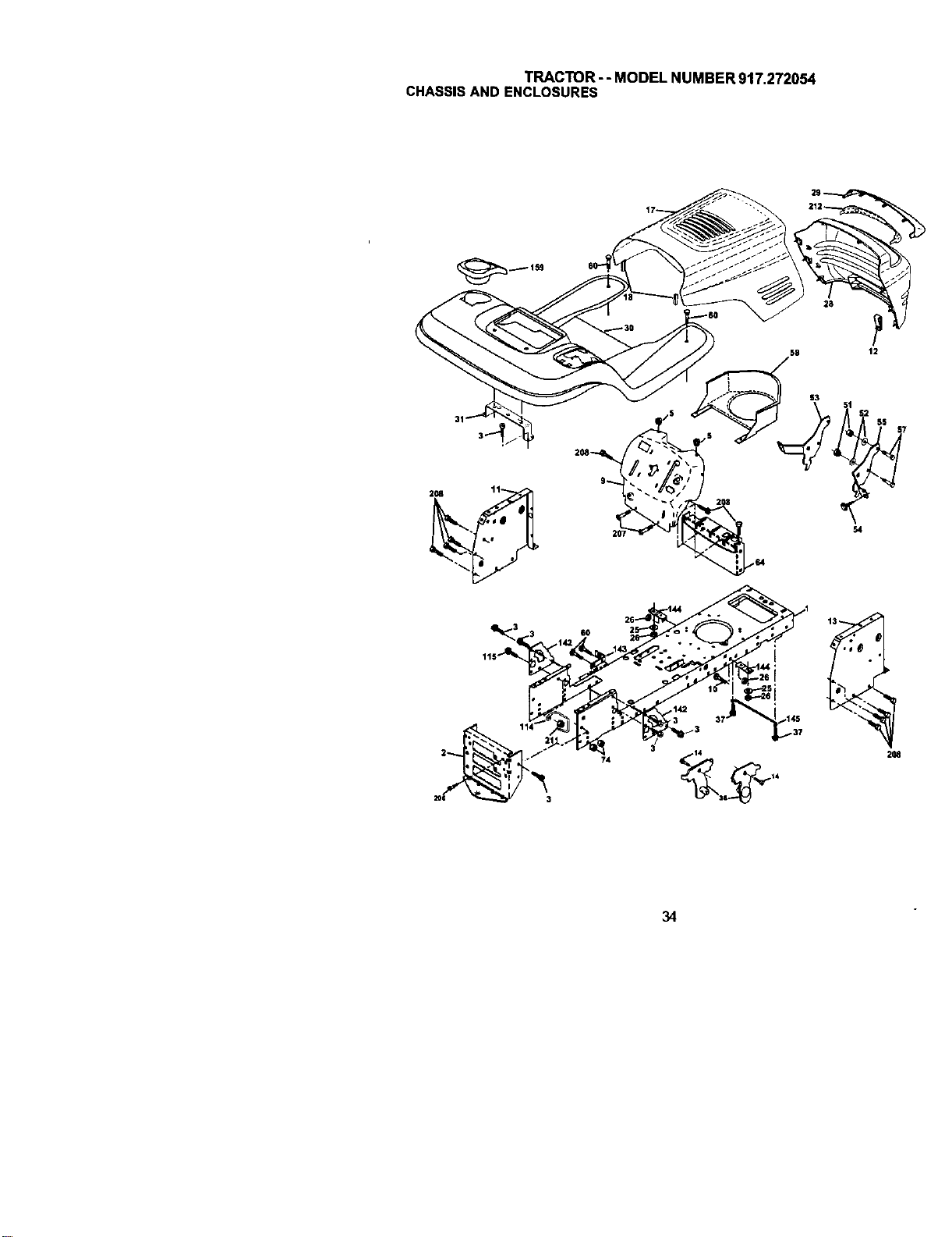
TRACTOR - - MODEL NUMBER 917.272054
CHASSISAND ENCLOSURES
58 12
S3
S4
74
2U
34
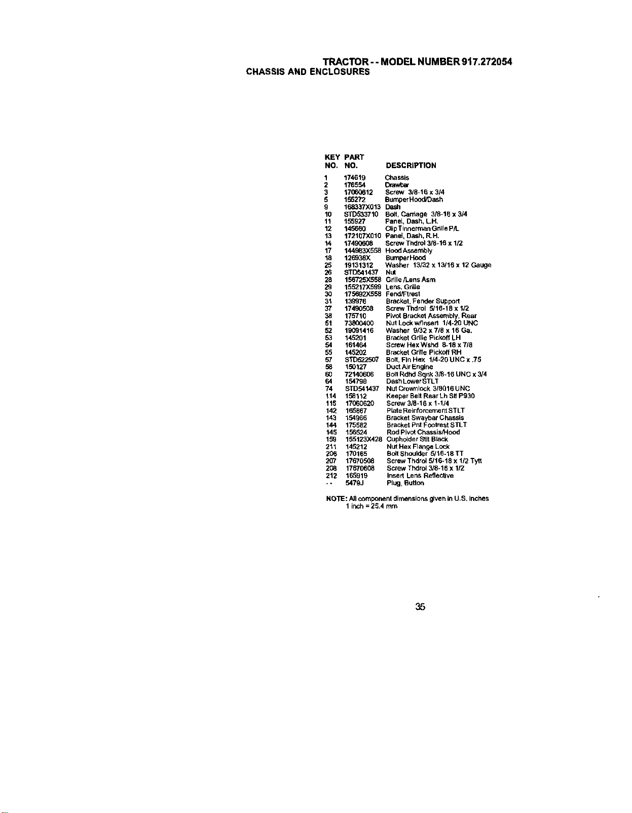
TRACTOR--MODELNUMBER917.272054
CHASSISANDENCLOSURES
KEY PART
NO, NO, DESCRIPTION
1 174619 Chassis
2 176554 Drav/oar
3 17060612 Screw 3/8-16 x 314
5 155272 BumperHoodOash
9 168337X013 Dash
10 STD533710 Boit, Carriage 3/8-16 x 3/4
11 155927 Panel, Dash, LH.
12 145660 ClipTinnerman G611eP/L
13 172107X616 Panel, Dash, R.H.
14 17490608 Screw Thdro1318-16 x 1/2
17 1449_3X558 Hood Assembly
18 126938X BumperHood
25 19131312 Washer 13/32 x 13/16 x 12 Gauge
26 BTD541437 Nut
28 156725X558 Gdlle/Lens Asm
29 155217X599 Lens, Grille
30 175692X558 Fend/F/rest
31 139976 Bracket, Fender Support
37 17490508 Screw Thdrol 5/16-18 x 112
38 175710 pivot Bracket Assembly, Rear
51 73800400 Nut Lockw/Insert 1/4-20 UNC
5_ 19091416 Washer 9/32 x718 x 16 Ga.
53 145201 Bracket Grille Pickoff LH
54 161464 screw Hex Wshd 8-18 x 7/8
55 145202 Bracket Grille Pickoff RH
57 STD522507 Bolt, Fin Flex 1/4-20 UNC x .75
58 150127 Duot Air Engine
60 72140606 Bolt Rdhd SqpJ_3/8-16 UNC x 3/4
64 154798 Dash Lower STLT
74 STD541437 NotCrownlock 318Q16UNC
114 158112 Keeper Bet/Rear Lh St1P930
1t5 17060620 Screw 3/8-16 x 1-114
142 165867 PLateReinforcement STLT
143 154966 BraCket Swaybar Chassis
144 175582 Bracket Pnt Footrest STLT
145 156524 Rod Pivot Chassis!Hood
159 158123)(428 Cupholder _tlt Black
211 145212 Nut Hex FlangeLOck
206 170165 BoltShoulder 5/16-18TT
207 17670508 Screw Thdrol 5/16-18 x 1/2 Tytt
2(_ 17670668 Screw Thdrol 3/8-16 x 112
212 165919 Insert Lens Reflective
- - 547gj Plug, Button
NOTE: _JIcomponent dimensions given In U.S. inches
1 Jr_ch= 25.4 mm
35
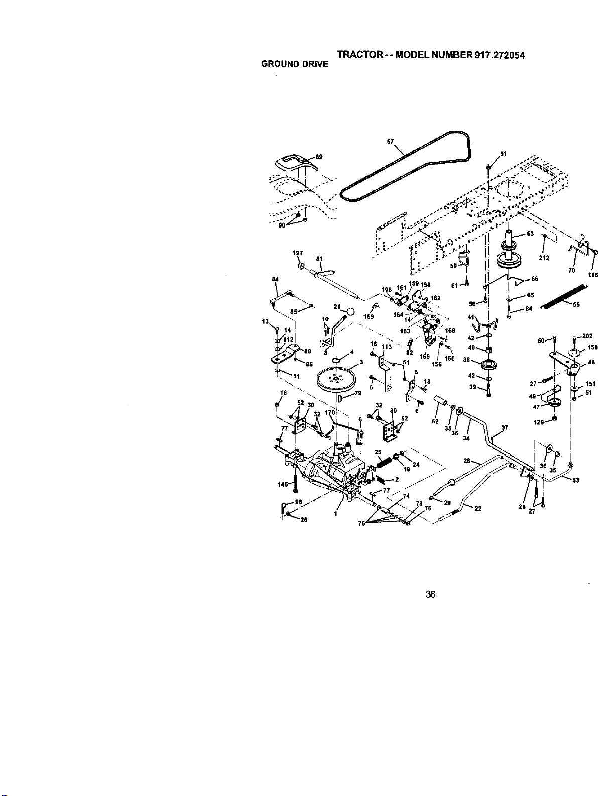
TRACTOR-- MODEL NUMBER 917.272054
GROUNDDRIVE
57
77
156
5
18
59
2t2
25 27
36
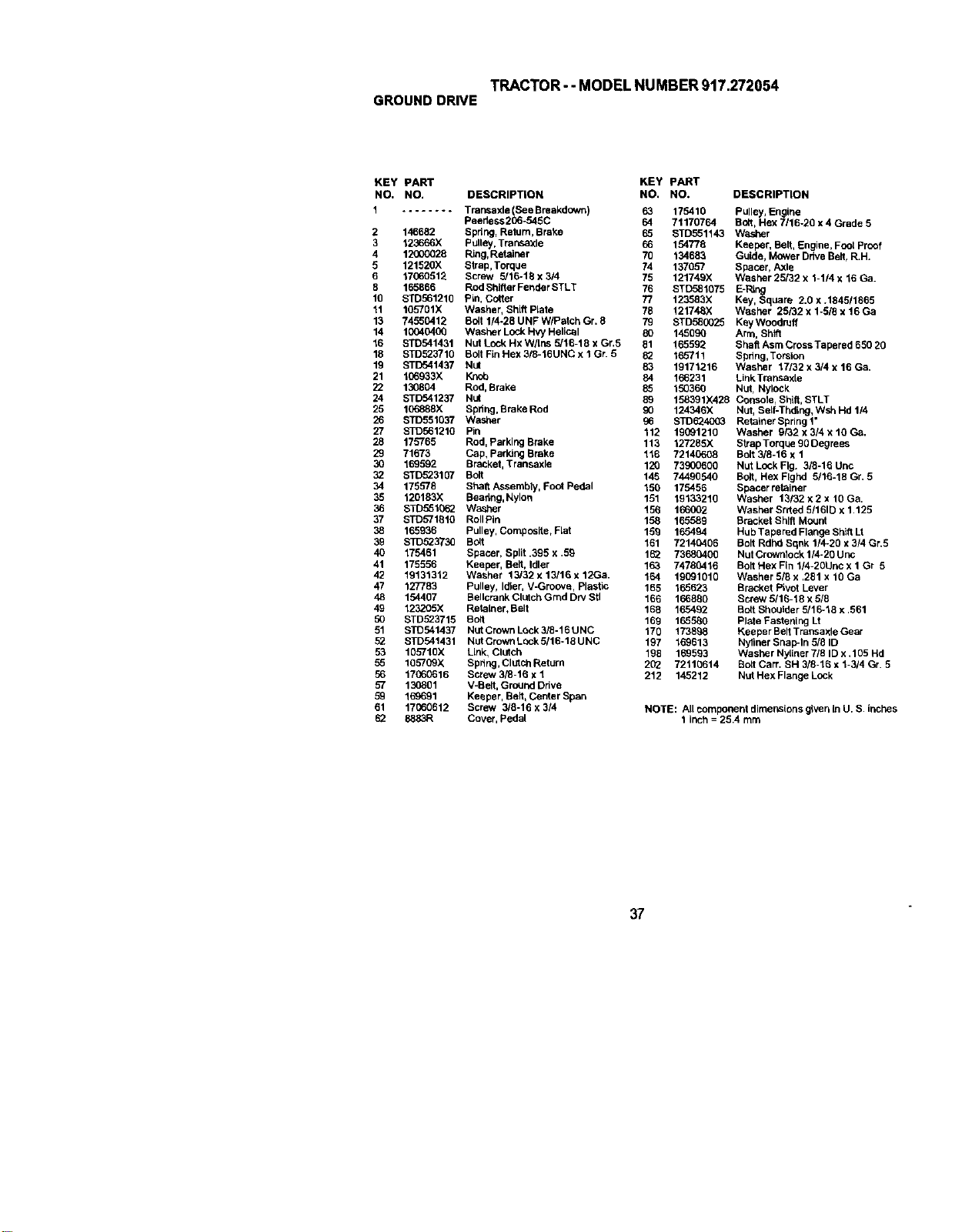
TRACTOR- - MODEL NUMBER 917.272054
GROUNDDRIVE
KEY PART KEY pART
NO. NO. DESCRIPTION NO. NO. DESCRIPTION
1 ........ Transaxle (See Breakdown) 63
2
3
4
5
6
6
16
11
13
14
16
18
19
21
22
24
25
26
27
28
29
3O
32
34
35
36
37
38
39
40
41
42
47
48
49
5O
51
52
53
55
56
57
59
61
62
Peedess 266-545C 64
146682 Spdng, Relum, Brake 65
123666X pulley, Transakie 66
12900028 Ring,Retainer 76
121520)( Strap,Torque 74
17060512 Screw 5/16-18 x 314 75
165866 Rod Shifter Fendar STLT 76
STD561210 Pin, Cotter 77
105701X Washer, Shift Rate 78
74550412 Bolt 1/4-28 UNF WIPutch Gr. 8 79
I0040/8XJ Washer Lock I-IvyHelical 80
STD541431 Nut Lock Hx W/Ins 5/16-16 x Gr,5 81
STD523716 Bolt Fin Hex 3/8-16UNC x I Gr. 5 82
STD541437 Nut 83
166933X KnC_ 84
130804 Rod, Brake 85
STD541237 Nut 89
106888X Spring, Brake Rod 90
STD551037 Washer 96
STD561210 Pin 112
175765 Rod, Parking Brake 113
71673 Cap, Parking Brake 116
169992 BraCket, Transaxle 120
BTD523107 Bolt 145
175578 Sheil Assembly, Foot Pedal 150
120183X Beadng, Nyloil 191
STD551062 Washer 156
STD571810 ROllPin 158
165936 Pulley, Composite, Rat 159
S]D62373O Bolt 161
175461 Spacer, Split .395 x .59 162
175596 Keeper, Belt, Idler 163
19131312 Washer 13/32 x 13/16 x 12Ga. 164
127763 Pulley, Idler, V-Groove, Plastic 169
154497 Bellcrank Clutch Grad Dry Stl 169
123205X RetaLner,Belt 166
STD923715 Bolt 169
STO541437 Nut Crown Lock3/6-16 UNC 176
STD541431 Nut Crown Lock 5/16-18 UNC 197
105710X Link, Clutch 196
165709X Spltng, Clutch Return 202
17C60616 Screw 3/8-16 x 1 212
130801 V-Belt, GroUnd Dltve
169691 Keeper, Belt,Center Span
17060612 Screw 3/8-16 x 3/4
8883R Cover, Pedal
175410 Pulley, Engine
71170764 Bolt, Hex 7116-20 x 4 Grade 5
STD551143 Washer
154778 Keeper, Belt, Engine, Fool Proof
134683 Guide, Mower Drive Belt,RIll.
137657 Spacer, Axle
121749X Washer 25/32 x 1-1/4 x 16 Ga.
STD581075 E-Ring
123583X Key, Square 2.0 x .1645/1865
121748X Washer 29/32 x 1-5/6 x 16 Ga
STD585O25 Key Woodruff
145090 Arm, Shift
165592 Shaft Asm Cross Tapered 656 26
165711 Spdng,Torsion
19171216 Washer 17/32 x 5/4 x 16 Ga.
166231 LinkTransaxie
150366 Nut, Nyloek
198391)(428 Console, ShLft,STLT
124346X Nut, Self-Thding, Wsh Hd 1/4
STD6_4003 Retainer Spdng1"
19091216 Washer 9/32 x 3/4 x 10 Ca.
127265X Strap TorqLe 90 Degrees
72140608 Bolt 3/8-16 x 1
73900600 Nut Lock Fig. 3/8-16 Unc
74490540 Bolt, Hex Flghd 5/16-18 Gr. 5
175456 Spacer retainer
19133219 Washer 13/32 x 2 x 10 Ga,
166002 Washer Srrted 5/161D x 1,125
165589 Bracket Shift Mount
165494 Hub Tapered Flange Sh_ Lt
72140406 Bolt Rdnd Sqnk 1/4-20 x 3!4 Gr.9
73680400 Nut Crownlock 1/4-26 U nc
74760416 Bolt Hex Fin 1/4-20Unc x 1 Gr 5
19091010 Washer 5/6 x ,261 x 10 Ga
165623 Bracket Pivot Lever
166880 Screw g116-18 x 5i6
165462 Bolt Shoulder 5/16-18 x .561
165560 Plate Fastening Lt
1738_8 Keeper Belt Transaxle Gear
169613 Nyliner Snap-In 5/8 ID
169593 Washer Nyliner 7/8 ID x .105 Hd
72116614 Bolt Cart. SH 3/8-16 x 1-3/4 Gr. 5
145212 Nut Hex Flange LOCk
NOTE: All component dimensions gWei3LnU. S. inches
1 inch = 25.4 mm
37
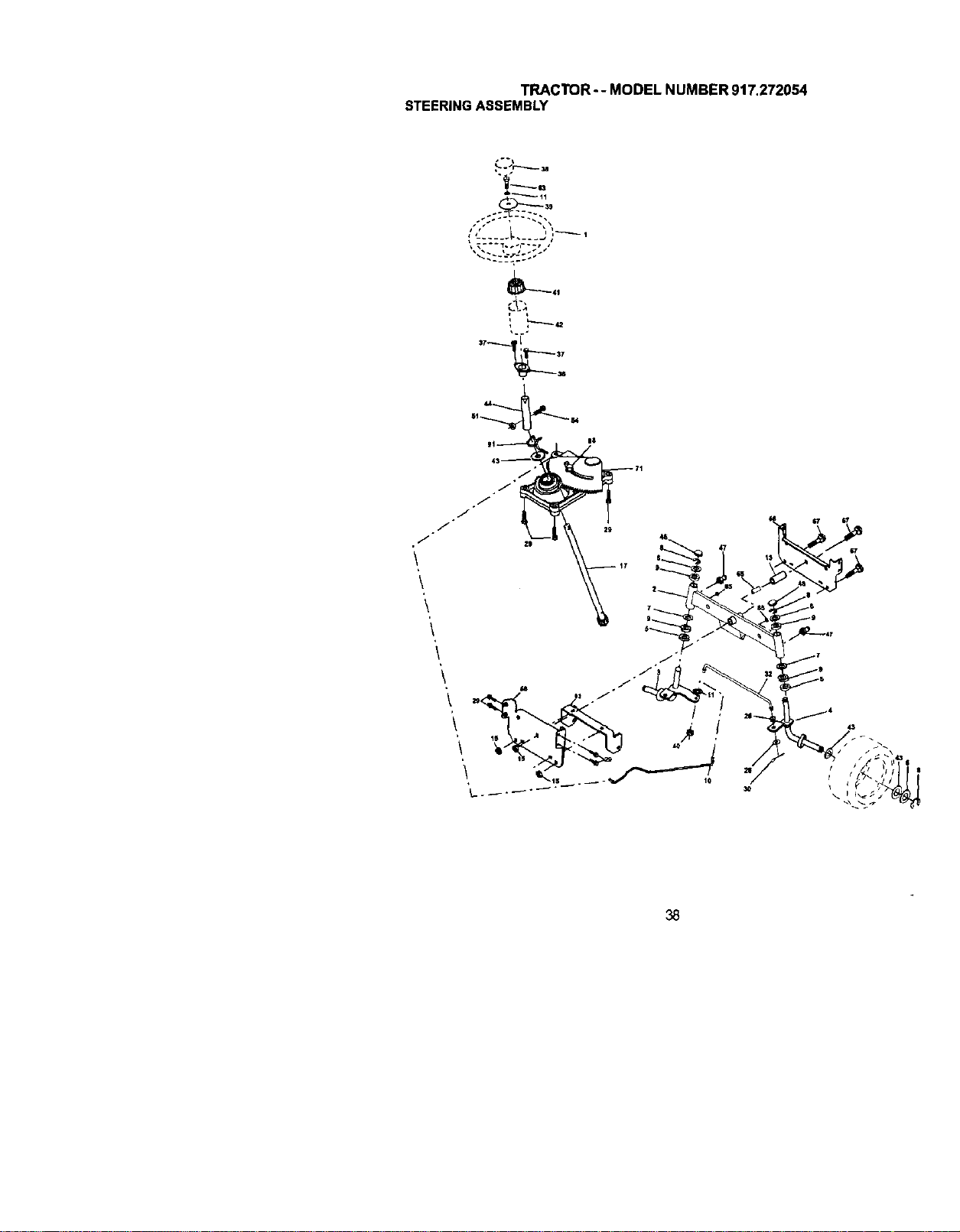
TRACTOR-- MODEL NUMBER 917.272054
STEERINGASSEMBLY
\
\
'\
3O
43
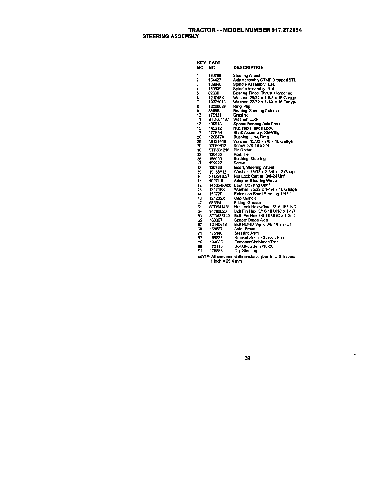
TRACTOR- - MODEL NUMBER 917.272054
STEERINGASSEMBLY
KEY PART
NO. NO. DESCRIPTION
1 139768 Sleeting Wheel
2 154427 Axle Assembly STMP Dropped STL
3 169840 Sl_ndle Assembly, LH.
4 169839 Spindle Assembly, R.H.
5 6265H Beadng, Race, Thrust, Hardened
6 121748X Washer 25/32 x 1-5/8 x 16 Gauge
7 19272916 Washer 27/32 x %1/4 x 19 Gauge
8 12000029 Ring, Ktip
9 3365R Bearing,Steer;ng Column
10 175121 Draglink
11 STD551137 Washer, Lock
13 136519 Spacer Beadng Axle Front
15 145212 Nut, Hex Flange Lock
17 177876 Shaft Assembly, Steering
26 126847X Bushing, Link, Drag
28 19131416 Washer 13/32 x 7/8 x 16 Gauge
29 17060612 Screw 3/8-16 x 3/4
30 STD651210 Pin Cotter
32 130465 Rod, Tie
36 155099 Bushiug, Steering
37 15_927 Screw
38 139769 Insert, Steering Wheel
39 19133812 Washer 13/32 x 2-3/8 x 12 Gauge
40 STD541537 Nut Lock Center 318-24 Unf
41 I00711L Adaptor, Steering Wheal
42 145054X428 Boot, Steertug Shaft
43 121749X Washer 25/32 x 1-t/4 x 16 Gauge
44 153720 Extension Shaft Steering LR.LT
46 121232X Cap, Spindle
47 6555M Fitting, Grease
51 $10541431 NutLockHexw/Ins. 5/16-18UNC
54 74790520 Bo_tFin Hex 5/16-18 UNC x 1-1/4
63 STD523710 Bolt, Fin Hex 3/9-16 UNC x 1 Gr 5
65 160367 Spacer Brace ASEe
67 72140618 Bolt RDHD Sqnk 3/8-16 x 2-1/4
65 165827 Axle1Brace
71 175146 Steerlug ASm,
169835 Bracket Susp. Chassis Front
85 133835 Fastener ChristrnasTree
65 175118 Bog Shoulder 7/16-20
91 175553 Clip Steedng
NOTE: All componerd dimensions given in U.S. inches
1 inch = 25.4 rnm
39
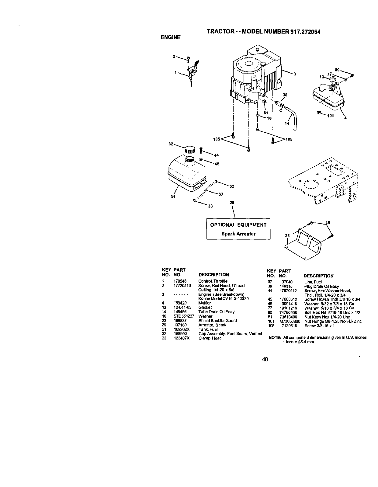
TRACTOR--MODELNUMBER917.272054
ENGINE
\
OPTIONAL EQUIPMENT
Spark Arrester
38
90
23
KEY PART
NO. NO. DESCRIPTION
1 170548 Control, Throffie
2 17720410 Screw, Hex Head, Thread
Cu6ing 1/4-20 x 518
3 ...... Engine, (See Breakdown)
KohlerModelCV 16,5-43530
4
13
14
16
23
29
31
32
33
159420 Muffler
12_41-03 Gasket
148456 Tube Drain Oil Easy
STD551237 Washer
169837 Shield BrrVDbrGuard
137180 Arrestor, Spark
109202)( Tank, Fuel
158990 Cap Assembly, Fuel Sears, Vented
123487X Clarhe, Hc6e
KEY PART
NO. NO, DESCRIPTION
37 137040 Line, Fuel
38 148315 Plug Drain Oil EaSy
44 17670412 Screw, Hex Washer Head,
Thd., Roll. 1/4-20 x 314
45 17000612 Screw Hxv_h Thdr 3/8-15 x 3/4
46 19091416 Washer 9/32 x 7/8 x 16 Ga
77 19101216 Washer 5/16 x 3/4 x 16 Ca,
80 74760508 BO6Hex Hd 5/16-16 Uric x 112
81 73510400 Nut Keps Hex 1/4-20 Uric;
101 M73030800 Nut Flange M8-1.25 Non=LkZinc
105 17120616 Screw3/8-16 x 1
NOTE: All component dimensions given In U,S. inches
t inch = 26.4 mm
4O
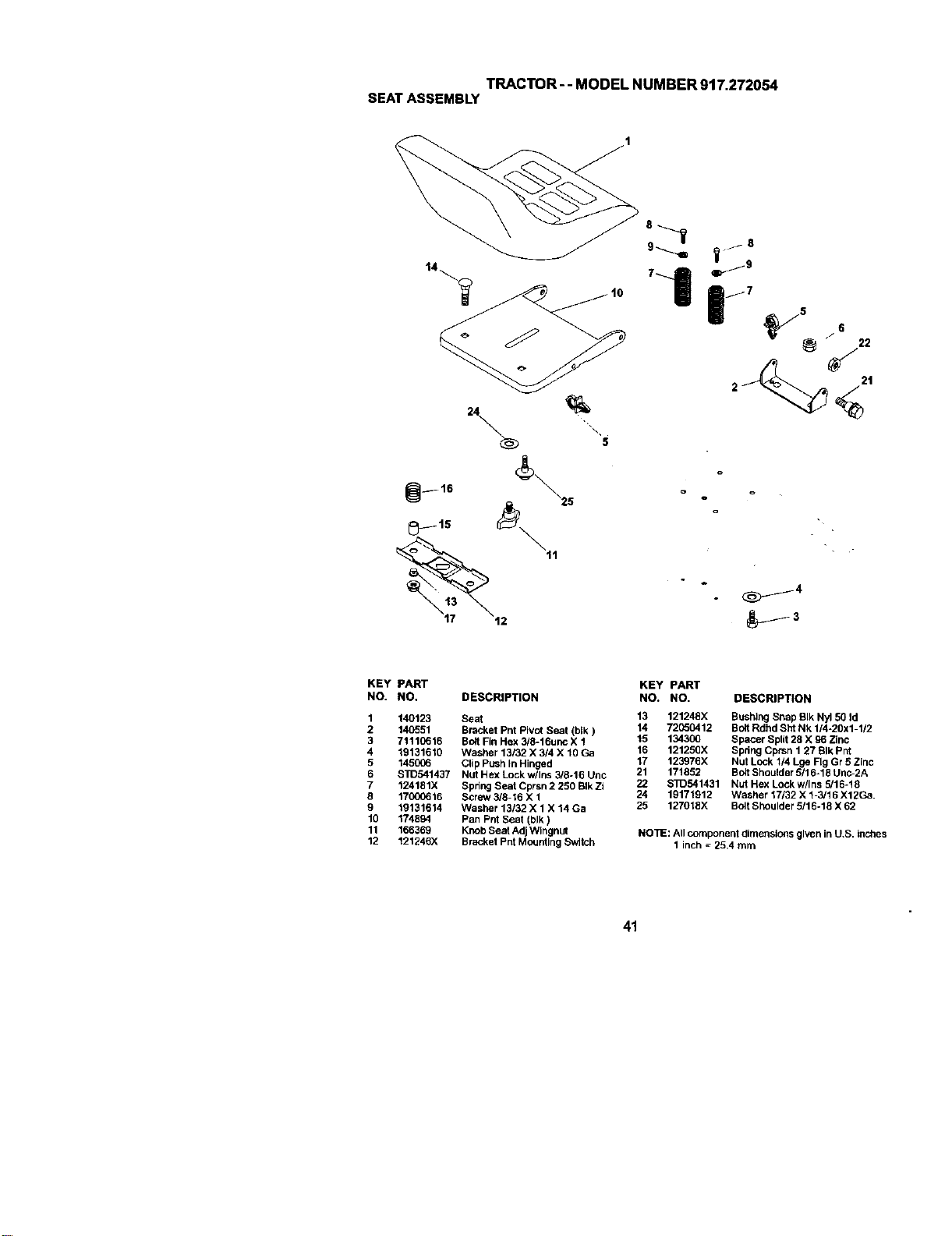
TRACTOR--MODELNUMBER917.272054
SEATASSEMBLY
KEY PART
NO. NO. DESCRIPTION
1 140123 Seat
2 140551 Bracket Pnt Pivot Seat (blk)
3 71110616 Bolt Fin Hex 3/8-16unc X 1
4 19131610 Washer 13/32 X 3/4 X t0 Ga
5 1450_6 Clip Push In Hinged
6 STD541437 Nut Hex Lock w/Ins 3/8-16 Unc
7 124181X Spdng Seat Cprsn 2 250 BIk Zi
8 17000616 Screw 3/8-16 X 1
9 19131614 Washer 13132 X 1 X 14 Ga
19 174894 Pan Pnt Seat (blk)
11 166369 Knob Seat Adj WIngnot
12 121246X Bracket Pnt Mounting Switch
KEY PART
NO. NO. DESCRIPTION
13 121248X Bushing Snap SIk Nyl 50 Id
14 72050412 Bolt Rdhd Sht Nk 1/4-20x1-1/2
15 134300 Spacer Split 28 X 96 Zinc
16 121250X Spdng Cprsn 1 27 BIk Pnt
17 123976X Nut Lock 1/4 Lge FigGr 5 Zinc
21 171852 Bolt Shoulder 5/16-18 Unc-2A
22 S]D541431 Nut Hex Lockw/Ins 5/18-18
24 19171912 Washer 17/32 X t-3/t8 X12Ga.
25 127018X Bolt Sheulder 5116-18 X 62
NOTE: All component dimensions given in U,S. inches
1 inch _ 25,4 mm
41
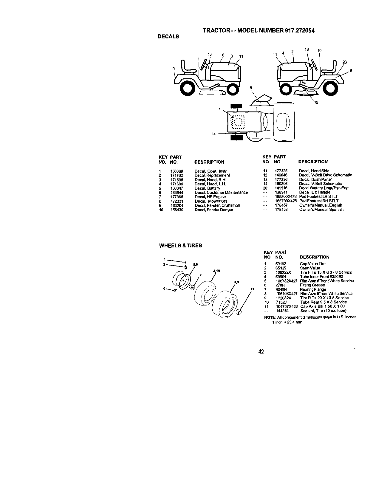
TRACTOR- - MODEL NUMBER 917.272054
DECALS
13 6 3 11
8
\
13 10
11
\ 2o
12
14
KEY PART
NO, NO.
t 156368
2 171762
3 171698
4 171699
5 138047
6 133644
7 177368
8 172331
5 163204
t0 156439
DESCRIPTION
Decat, Oper. Instr.
Decal, Replacernerd
Decal, Hood, R.H.
Decal, Hood, LH.
Decal, Battery
Decal, Customer Mafntenance
Decal, HP Engine
Decal Mower Srs
Decal, Fender, Craftsman
Decal, Fender Danger
KEY PART
NO. NO. DESCRIPTION
11 177325 Decar, Hood Side
12 146046 Decal, V-Belt Ddve Schematic
13 177336 Decat, Dash Paner
14 160396 DecaJ, V-Belt Schematic
20 149516 Decal Battery DngdPsn Eng
- - 138311 Decal, Lift Handle
- - 165800X428 Pad Footrest LH STLT
o- 165799X428 Pad Footrest RH STLT
- - 178457 Owner's Manual, Englich
- = 178458 Owner's Manual, Spanish
WHEELS &TIRES
5,8
4,10
KEY PART
NO. NO. DESCRIPTION
1 591_ Cap Value Tire
2 65139 StemVa_ue
3 106222X Tire F Ts 15 X 6 0 - 6 Service
4 99904 Tube IrmerFront#35960
5 106732X427 Rim Asm 6"fTontWhite Service
6 278H Fitting Grease
7 9040H Bealtng Flange
9 106108X427 RimAsm 5"rear White Set/ice
g 122062X Tire R Ts 20 X 10-8 Service
10 7152J Tube Rear 9 5 X 8 Sewice
11 104757)(428 Cap Axle BIk t 50 X 1 00
144334 Seatant, Tire (10 oz. tube)
NOTE; Allcomponent dimensionsgiven in U.S. inches
1 inch= 25.4 mm
42

TRACTOR- - MODEL NUMBER 917.272054
LIFTASSEMBLY
2O
6
15
2O
KEY PART KEY pART
NO. NO. DESCRIPTION NO. NO. DESCRIPTION
1 159460 Washar i_sm Inner SpringW/ 13 STD624008 RetainerSpring
Plunger 15 173288 LinkFront
2 159471 Shaft Asm. Ufl 16 73350800 NutJam Hex 1/2-13 Unc
3 105767X Pin Groove 17 130171 TrunnionBIk Zinc
4 12000_T2 ERing#5133-62 18 73800800 Nut LOCkw/Wsh 1/2-13 Unc
5 19211621 Washer 21/32 x 1 x 21 Ga. 19 139888 ArrnSuspension Mower
6 120183X BearingNylong 20 163552 Retainer Spring
7 125631X Gdp Handle FlUted 31 169865 Bearing, Pvt. Lift
8 122365)( BuftonPlunger Read 32 73540600 Nutcrownlock 3/8-24
1t 139865 Link Asm Lift LH.
12 139866 LinkAsm Lift R,H. NOTE: All component dimensions given in U.S. inches
1 inch = 25.4 rnm
43
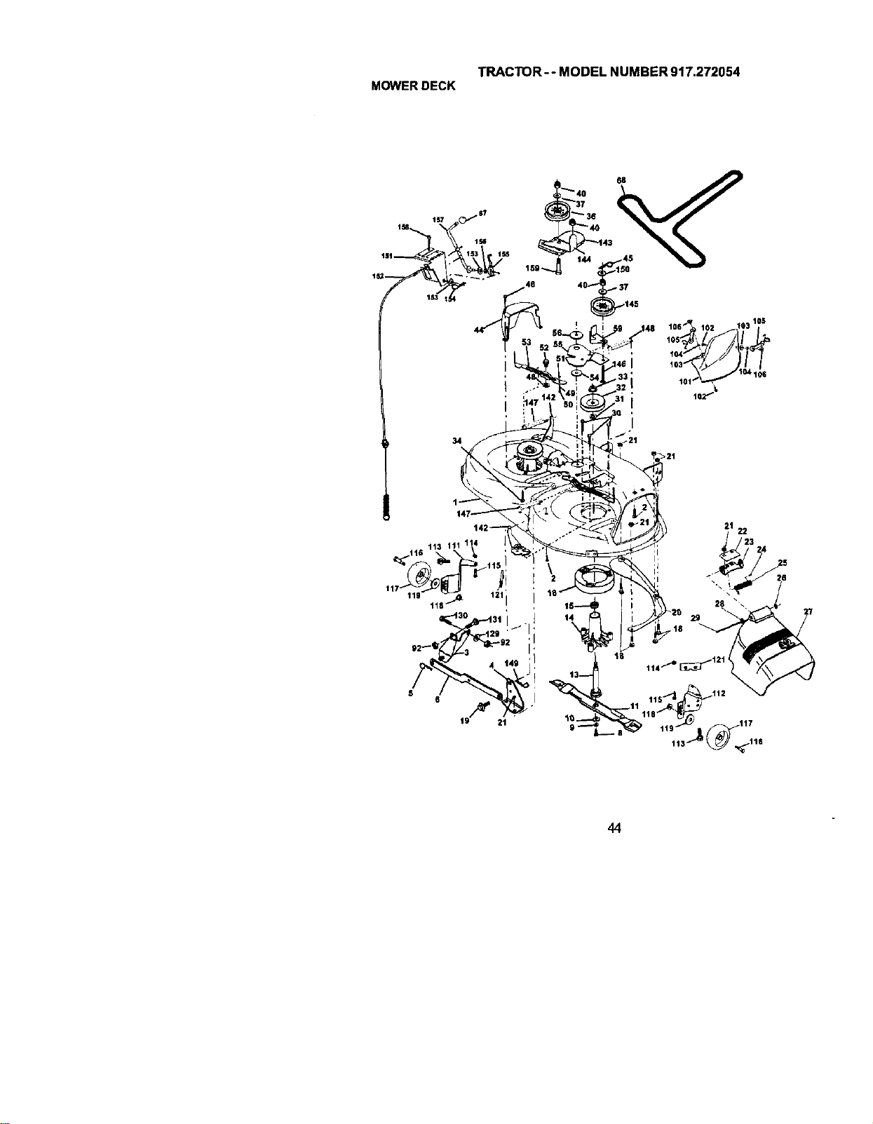
TRACTOR-- MODEL NUMBER 917.272054
MOWERDECK
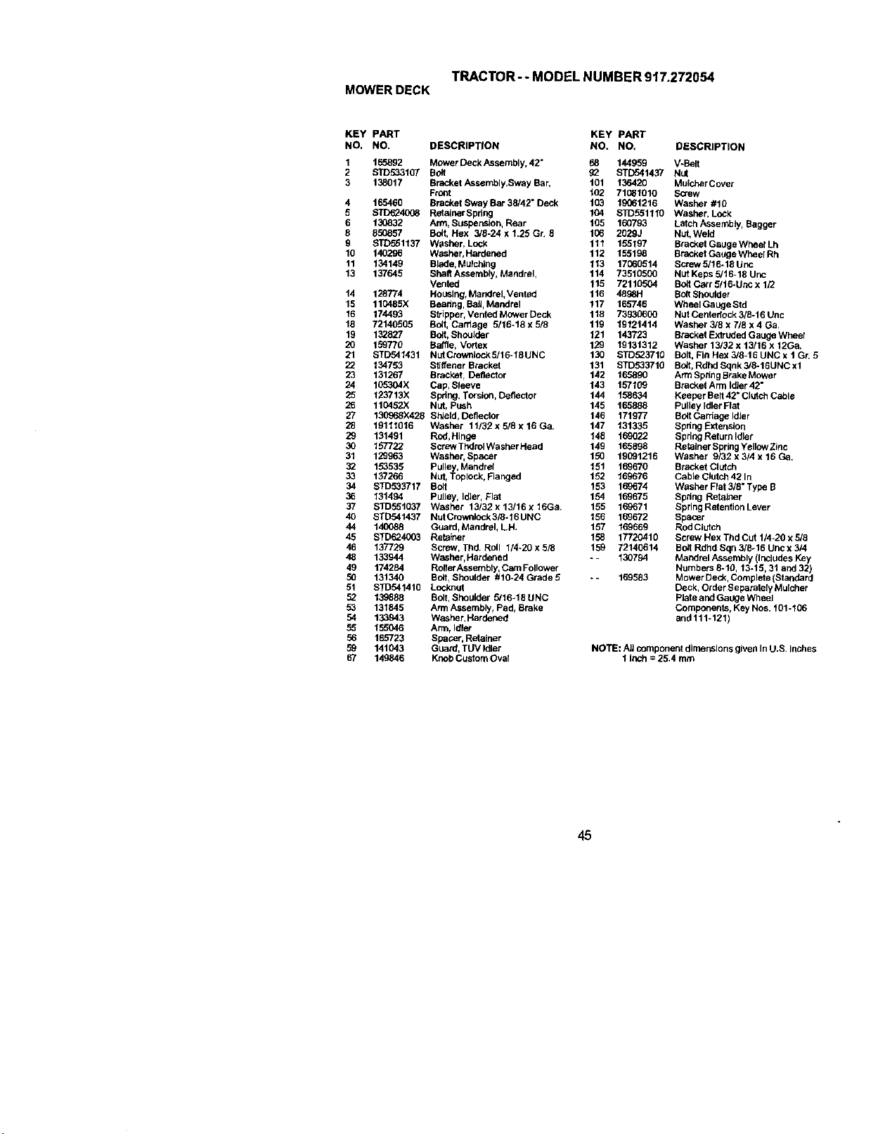
TRACTOR--MODELNUMBER917.272054
MOWERDECK
KEY PART KEY PART
NO. NO. DESCRIPTION NO. NO. DESCRIPTION
1 165892 Mower Deck/_ssembly, 42" 68 144959 V-Belt
2 STD693107 Bolt g2 STD541437 Nut
3 138017 Bracket/Lssembly,Sway Bar, t01 136420 Mulcher Cover
FrGnt t02 71081010 Screw
4 165460 Bracket Sway Bar 38/42" Deck 103 19061216 Washer #10
5 STD624_8 RatolnerSpring 104 STD551110 Washer, LoCk
6 130832 Arm, Suspension, Rear 105 160793 Latch Assernbly_Bagger
8 850857 Bolt, Hex 3/g-24 x 1.25 Gr. 9 106 2029J Nut, Weld
g STD551137 Washer, Lock 111 155197 Bracket Gauge Wheol Lh
10 140296 Washer, Hardened 112 155198 Bracket Gange Wheol Rh
11 134149 Blade,Mulchteg 113 17G60514 Screw 5/16-18 Unc
13 137645 Shatt Assembly, Mandrel, 114 73510500 Nut Keps 5/16-18 Unc
Vented 115 72110504 BUd C_rr 5/16*Unc x 1/2
14 128774 Housing, Mandrel,Vented 116 4898H Bog Shoutder
15 110485X Beadr_g,Bail, Mandrel 117 165746 Wheel Gauge Std
15 174493 Sb'ipper, Ventad Mower Deck 118 73930600 Nut Centadock 3/5-16 Uac
18 72140505 Bolt, Carriage 5/lg-18 x 5/5 119 19121414 Washer 3/8 x 7/8 x 4 Ga
19 132827 Bolt,Shoulder 121 143723 Btackat Extruded Gauge Wheel
20 159770 Baffle, Vortex 129 19131312 Washer 13132 x 13/16 x 12Ca.
21 STD541431 NutCrownteckg/16-18UNC 130 STD523710 Bolt, Fin Hex 3/6-15 UNC x t Gr. 5
22 134753 S6ffener Bracket 131 STD53371B Bolt, Rdnd Sqnk 3/8-16UNC xl
23 131267 Bracket, DefleCtor 142 165890 ArrnSpdngBrakeMower
24 105304X Cap, Sleeve 143 157109 Bracket Arm IdJer42"
25 123713X Spring, Torsion, Det]ector 144 158634 Keeper Bed42 ° Clutch Cable
26 110452)( Nut, Push 145 165888 Pulley Idler Fiat
27 130968X425 Shield, Deflector 146 171977 BoltCardage Idler
28 19111916 Washer 11/32 x 5/8 x 16 Ga. 147 131335 Spdng Extension
29 131491 Rod, Hinge 148 169022 SpringRetarn Idler
30 157722 ScrewTedmlWasher Head 149 165898 Reteiner Spdng Yellow Zinc
31 129963 Washer, Spacer 150 19091216 Washer 9/32 x 3/4 x I g Ca.
32 153535 Pulley, Mandrol 151 169670 Bracket Clutch
33 137266 Nut, Toplock, Flanged 152 169676 Cable Clutch 42 In
34 $TD693717 Bolt 153 169674 Washer Flat 3/8" Type B
36 131494 Pulley, Ioler, Flat 154 169675 Spdng Retainer
37 STD55t037 Washer 13/32x13/16xt6Ga. 155 169671 SpringRatentionLever
40 STD541437 NutCmwatock3/8*16UNC 156 169672 Spacer
44 140088 Guard, Mandrel, LH. 157 169669 Rod Clatch
45 STD624003 Retainer 158 17720410 Screw Hex Tbd Cut 1/4-20 x 5/8
46 137729 Screw, Thd. Roll 1/4-2g x 5/9 159 72140614 Bolt Rdhd Sge 3/8-16 Unc x 3/4
48 133944 Washer, Hardened - - 130794 Mandrel Assembly (Includes Key
49 174284 RattarAssembly, Carn Follower Nurnbers 8-10, 13-15, 31 and 32)
50 131340 Bolt, Shoulder #10-24 Grade 5 -- 169583 Mower Deck, Complete (Standard
51 STD541410 Locknut Ceck, OrderSeperatelyMulcher
52 139888 Bolt, Shoulder 5/16-18 UNC Plata aed Gange Wheel
53 131845 Arm Assembly, Pad, Srake Components, Key Nos. 101-106
54 133943 Washer, Hardened and 111-121)
55 155046 Arm, Idler
69 165723 Spacer, Ratafner
69 141043 Guard, TUV Idler NOTE: All component dimensions given In U.S inches
67 149846 Knob Custom Oval 1 Inch = 25.4 rnrn
45
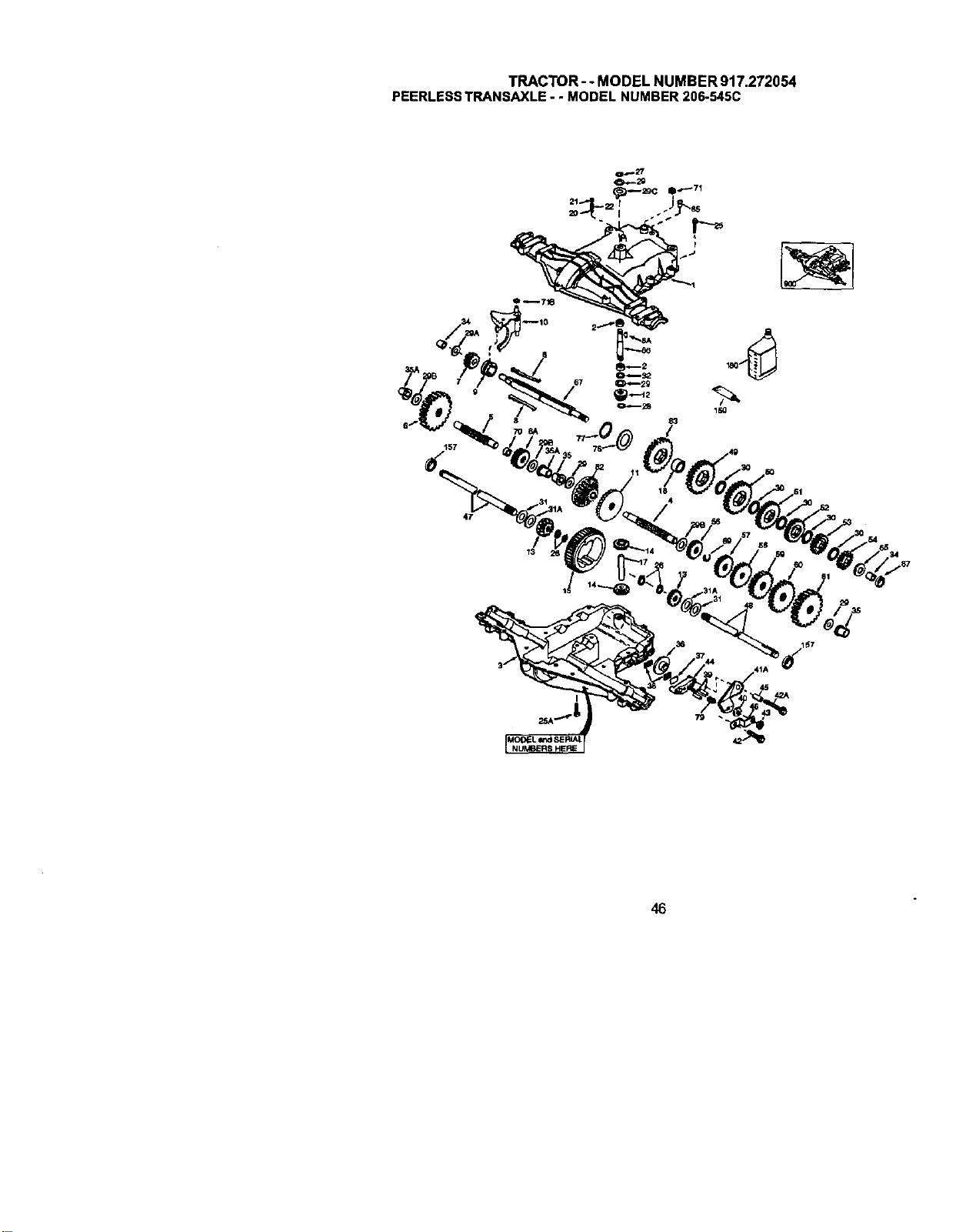
TRACTOR- - MODEL NUMBER 917.272054
PEERLESSTRANSAXLE- - MODELNUMBER206-545C
83
47
46
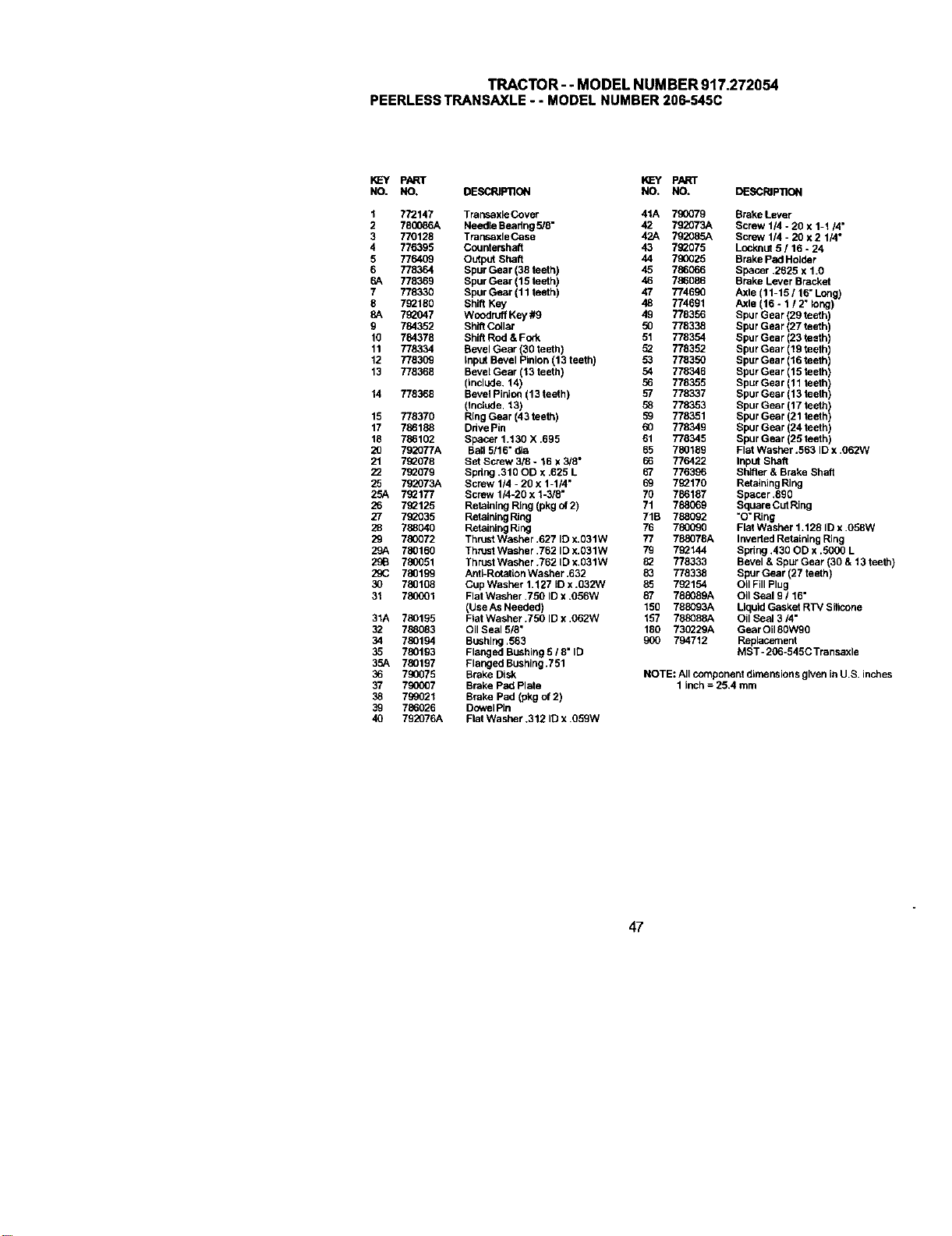
TRACTOR--MODELNUMBER917.272054
PEERLESSTRANSAXLE- - MODELNUMBER206-545C
KEY PART KL=Y PART
NO. NO. DESCRIPllON NO. NO. DESCRIPTION
1 772147 Transaxle Cover 41A 790079 Brake Lever
2 780086A Needle Beadng 5/8" 42 792073A Screw 114- 20 x 1-1/4"
3 770128 TransaxleCase 42A 792085A Screw 1/4 - 20 x 2 1/4"
4 776395 Countershaft 43 702075 Locknut 5 / 16 - 24
5 776409 Output Shaft 44 790025 Brake Pad Hetder
6 778364 Spur Gear (38 teeth) 45 786066 Spacer .2625 x 1.0
6A 778369 Spur Gear (15 teeth) 46 786086 Brake Lever Bracket
7 778330 Spur Gear (11 teeth) 47 774690 Axle (11-15 / 16" Long)
8 702180 Shift Key 48 774691 Axle (16 - 1 / 2" long)
8A 792047 Woodruff Key #9 49 778356 Spur Gear (29 teeth)
9 784352 Shift Collar 50 778338 Spur Gear (27 teeth)
10 784378 Shift Rod & Fork 51 778354 Spur Gear (23 teeth)
11 778334 Bevel Gear (30 teeth) 52 778352 Spur Gear (19 teeth)
12 778309 input Bevel Pinion (13 teeth) 53 778350 Spur Gear (16 teeth)
13 779368 Bevel Gear (13 taeth) 54 778346 Spur Gear (15 teeth)
(include. 14) 56 778355 Spur Gear (11 teeth)
14 778368 Bevel Pinion (13 teeth) 57 778337 Spur Gear (13 teeth)
(teclude. 13) 58 778353 Spur Gear (17 teeth)
15 778370 Ring Gear (43 teeth) 59 778351 Spur Gear (21 teeth)
17 786188 Ddve Pin 60 778349 Spur Gear (24 teeth)
18 786102 Spacer 1.130 X .695 61 778345 Spur Gear (25 teeth)
20 792077A Bali 5/16" dim 65 780189 Flat Washer .563 ID x ,062W
21 702078 Set Screw 318 - 16 x 3/8" 66 776422 Input Shaft
22 7_079 Spdng .310 OD x .625 L 67 776396 Shifter & Brake Shetl
25 792073A Screw 1/4 - 20 x 1-1/4" 69 7_170 Retaining Ring
25A 702177 Screw 1/4-20 x 1-3/8" 70 786187 Spacer .890
26 7_125 Retaining Ring (pkg of 2) 71 788069 Square Cut Ring
27 702035 Retaining Ring 71B 788092 "0" Ring
28 788040 Retaining Ring 76 780090 Flet Washer 1.128 ID x .058W
29 780072 Thrust Washer .627 ID x.031W 77 788079A Inverted Retaining Ring
29A 780160 Thrust Washer .762 ID x.O31W 79 7_144 Spdng .430 OD x .5000 L
296 780051 ThrUStWasher .762 ID x.031W 022 778333 Bevel & Spur Gear (30 & 13 teeth)
29(; 780199 AetI-Rota8on Washer .632 83 778338 Spur Gear (27 teeth)
30 780108 Cup Washer 1.127 IDx .032W 85 7_154 Oil Fill Plug
31 78(_01 Flat Washer .750 ID x .056W 87 788089A Oil Seal 9 116"
(Use As Needed) 150 788093A LiquidGasket RTV Silloone
31A 780195 Fiat Washer .750 ID x .062W 157 788088A Oil Seal 3/4"
32 788083 Oil Seal 5/8" 180 730229A Gear Oil80W90
34 780194 Bushing .563 900 794712 Replacement
35 780193 Flanged Bushing 5 18" ID MST -206-545C Transaxle
35A 780197 Flanged Bushing.751
36 790075 Brake Disk NOTE: All component dimensions given inU.S. inches
37 790007 Brake pad Plate 1 inch = 25,4 mm
38 799021 Brake Pad (pkg of 2)
39 786029 Dowel Pin
40 792076A Flat Washer .312 ID x .059W
47
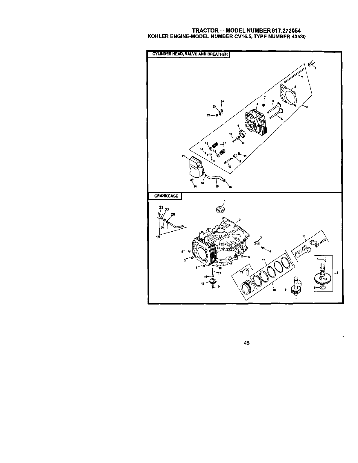
TRACTOR--MODELNUMBER917.272054
KOHLERENGINE-MODELNUMBERCV16.5,TYPENUMBER43530
CYLINDER HEAD, VALVE AND BREA'I_IER I
CRANKCASI_ I
23
/
@
48
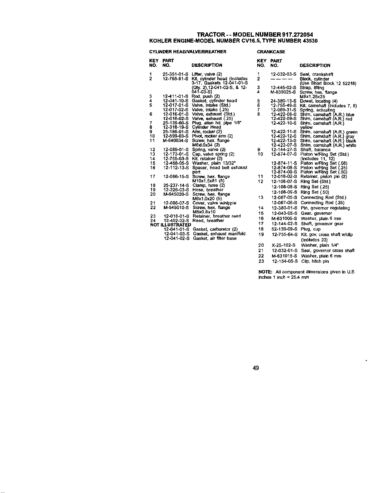
TRACTOR-- MODEL NUMBER 917.272054
KOHLERENGINE-MODELNUMBERCV16.5,TYPE NUMBER43530
CYLINDER HEAD/VALVE/BREATHER CRANKCASE
KEY pART KEY PART
NO. NO. DESCRIPTION NO, NO. DESCRIPTION
1 25-351-01-S Lifter, vane (2) 1 12-032-03-S Seal, crankshaft
Kit, cylinder head Includes
2 12-755-fl%S 3-17, Gaskets 12 (In_)4 2 BlOCk, cylinder
1-01-S (Use Short BlOCk 12 52218
(Qty. 2),12-041-O2-S, & 12- 3 12-445-02-S S rap, ifUng
041-03-S) 4 M-839025-S screw, hex. flange
3 12-411-01-S Rod, pt._h (2) MSx1.25x25
4 12-041-10-S Gasket, cylinder head 5 24-3B0-13-S Dowel locating (4)
5 12-017-01-S Valve, intake (Std.) 6 12-755-49-S Kit, camshaft (Includes 7, 8)
12-017-02-S Valve, intake (.25) 7 12-089-31-S Spdng, actuatinglA /
6 12-016-01-S Valve, exhaust (Std.) 5 12-422-08-S Shim, camshaft A.R. blue
12-016-02-S Valve, exhaust (.25) 12-.422-09-S Shim, camshaft .R. red
7 25-139-60-S Plug, allen hal. pipe 1/8" 12-422-10-S Shim, camshaft (A.R.)
8 12-318-19-S Cylinder Head yellow
9 25-186-01-S Arm, rocker(2) 12-422-11-S Shim, camshaft (A.R.) green
10 12-599-03-S Pivot, rocker arm (2) 12-422.12-S Shim, camshaft A.R.) gray
11 M-640034-S Screw, hex. flange 12-422-13-S Shim, camshaft (A,R.) black
M6xl.Ox34 (2) 12-422-07-S Shim, camshaft ()A.R. white
12 12-089-01-S Spdng, valve (2) 9 12-144-27-S Shaft, balance
13 12-173-01-S Cap, valve spdng (2) 10 12-874-07-S Piston w/Ring Set (Std)
14 12-755-03-S Kit, retainer (2) (Includes 11, 12)
15 12-468-05-S Washer, plain 13132" 12-874-11-S Piston w/Ring Set (.08
16 12-112-13-S Spacer, head bolt exhaust 12-874-08_._ platon w/Ring Set (.25)
port 12-874-09-S piston w/Ring Set ().50
17 12-086-15-S Screw, hex. flange 11 12-018-02-S Retainer, piston pin (2)
M1OxL5x81 (5) 12 12-108-07-S Ring Set (Std.}
18 25-237-14-S Clamp, hose (2) 12-108-08-S Ring Set (.25)
19 12-326-03-S Hose, breather
20 M-645020-S Screw, hex. flange 12-108-09-S Ring Set (.50)
M6xl.Ox20 (5) 13 12-067-05-S Conneodng Rod (Std.)
21 12_396-07-S Cover, valve w/ntpple 12-067-06-S Connecting Rod (.25)
22 M-545010-S Screw, hex. flange 14 12-380-01-S Pin, governor regulating
M5x0.8xlO 15 12-043-05-S Gear, governor
23 12-018-01-S Retainer, breather reed
24 12-402-02-S Reed, breather 16 M-631005-S Washer, plain 6 mm
NOT ILLUSTRATED 17 12-144-02-S Shaft, governor gear
12-041-01-S Gasket, carburetor (2) 18 52-139-09-S Plug, cup
12-041-03-S Gasket, exhaust manifold 19 12-755-64-S Kit, gov. cross shaft w/cUp
12-041-02-S Gasket, air filter base (includes 23)
20 X-25-102-S Washer, plain 1/4"
21 12-032-01-S Seal, governor cross shaft
22 M-631015-S Washer, plain 6 mm
23 12-154-05-S Clip, hitch pin
NOTE: Allcomponent dimensionsgiven In U.S
Inches I Inch = 26.4 mm
49
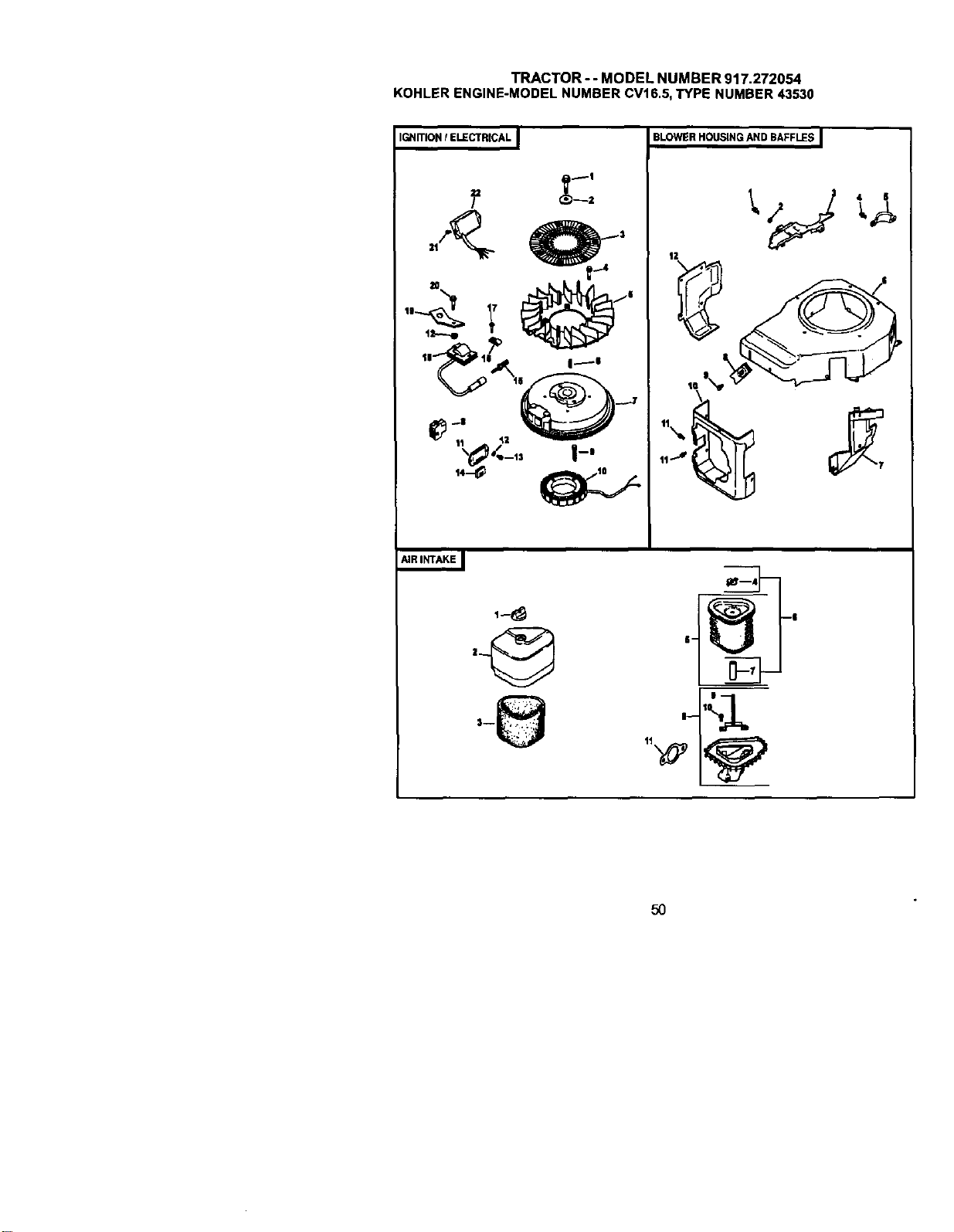
TRACTOR- - MODEL NUMBER 917.272054
KOHLERENGINE-MODELNUMBERCV16.5,TYPENUMBER43530
IGNITION! ELECTRICALI
'_._ _
_ "___
_'0<-,, I-'
14-:0
,@
BLOWER HOUSING AND BAFFLES I
6-
I--
11_'14
5O
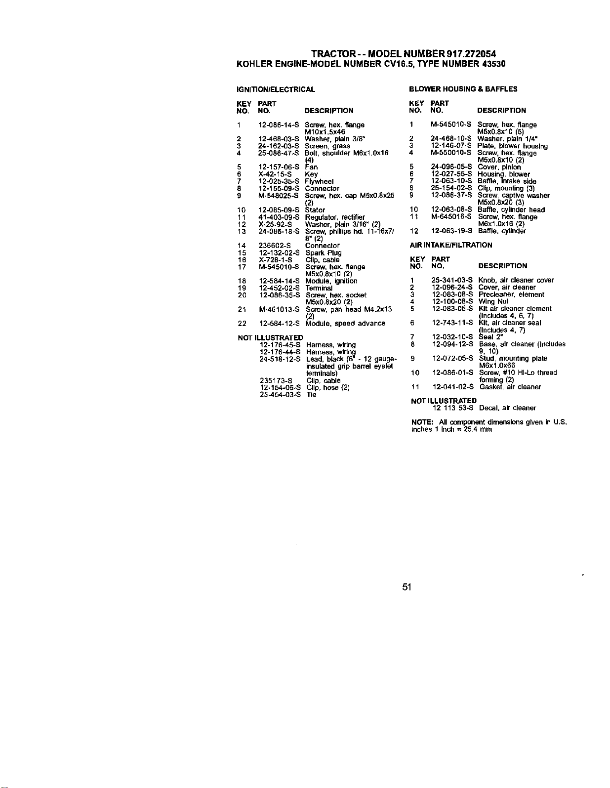
TRACTOR-- MODEL NUMBER 917.272054
KOHLERENGINE-MODELNUMBERCV16.5,TYPE NUMBER43530
IGNITION/ELECTRICAL
BLOWER HOUSING & BAFFLES
KEY PART KEY PART
NO. NO. DESCRIPTION NO. NO. DESCRIP_ON
1 12-086-14-S Screw, hex. flange 1 M-54501g-s Screw, hex. flange
M10xl.5x46 M5x0.8xl0 (5)
2 12-468-03-S Washer, plain 3/8" 2 24-468-10-S Washer, plain 1/4"
3 24-162-03-S Screen, grass 3 12-146-07-S Plate, blower housing
4 25-086-47.S Bolt, shoulder M6x1.Ox16 4 M-550010-S Screw, hex. flange
(4) M5xO.8xlO (2)
5 12-157-06-S Fan 5 24-096-05-S Cover, pinion
6 X-42-15-S Key 6 12-027.55-S Housing,, blower
7 12-025-35-S Flywheel 7 12-063-10-S Baffle, intake side
8 12-155-09-S Connector 8 25-154-02-S Clip, mounting (3)
9 M-548025-S Screw, h_(. cap M5xO.Sx25 9 12-086-37-S Screw, captive Washer
(2) M5xg.Sx2O (3
10 12-085-09oS Stator 10 12-063-08-S Baffle, cy nder head
11 41-403-09-S Regulator, rectifier 11 M-645016-S Screw, hex. flange
12 X-25-92-S Washer, plain 3/16" (2) M6x1.0x16 (2)
13 24-086-18_S Screw, phillips hd. 11-16x7/ 12 12-063-19-S Baffle, cylinder
8" (2)
14 236602-S Connector AIR INTAKE/FILTRATION
15 12-132-02-S Spark Plug
16 X-728-1 -S Clip, cable KEY PART
17 M-545010-S Screw, hex. flange NO. NO. DESCRIPTION
M5X0.8xl0 (2)
18 12-584-14÷S Module, Ignition 1 25-341-03-S Knob, air cleaner cover
19 12-452-02÷S Terminal 2 12-g96-24-S Cover, air cleaner
20 12-086-35-S Screw, hex. socket 3 12-083-08-S Precleaner, element
M5x0.8x2O (2) 4 12-10g-08-S Wing Nut
12-083-05-S Kg air claaner element
21 M-461013-S Screw, pan head M4.2x13 5
(2) Includes 4, 6, 7)
22 12-584-12_S Module, speed advance 6 12-743-11-S Kt, alrceanerseal
(Includes 4, 7)
NOT ILLUSTRATED 7 12-032-10-S Seal 2"
12-176_.5-S Harness, wiring 8 12-094-12-S Base, air cleaner (Inclades
12-176-44÷S Harness, wiring 9, 10)
24-518-12-S Lead, black (6" - 12 gauge- 9 12-072-05-S Stud, mounting plate
insulated grip barrel eyelet M6x1.0x66
terminals) 10 12-g86-01-S Screw, #10 HI-Lo thread
235173-S Clip, cable forming (2)
12-154-g6÷s Clip, hose (2) tl 12-041-02-S Gasket, air cleaner
25-454-03÷S Tie
NOTILLUSTRATED
12 113 535 Decal, aircleaner
NOTE: All component dimensions given in U.S.
Inches 1 Inch = 25.4 mm
51
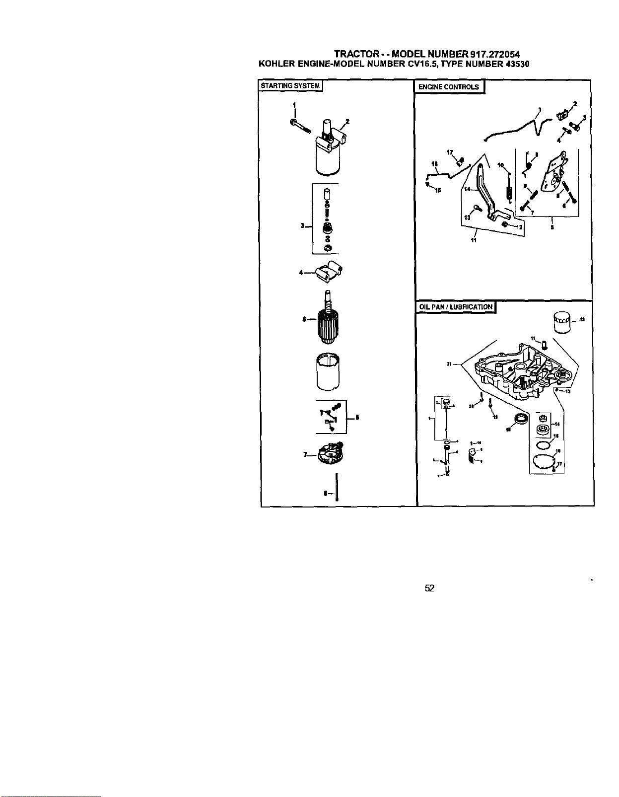
TRACTOR- - MODEL NUMBER 917.272054
KOHLERENGINE-MODELNUMBERCV16.5,TYPE NUMBER43530
STARTING SYSTEM I
0
==
=>
ENGINE CONTROLS I
tl
OIL PAN / LUBRICATION I
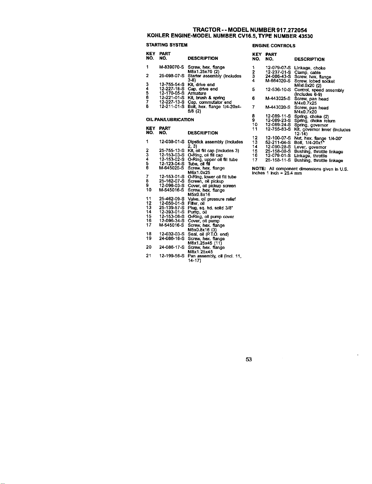
TRACTOR - - MODEL NUMBER 917.272054
KOHLERENGINE-MODELNUMBERCV16.5,TYPE NUMBER43530
STARTING SYSTEM
ENGINE CONTROLS
KEY PART KEY PANT
NO. NO. DESCRIPTION NO. NO.
DESCRIPTION
1 M-639070-S Screw, hex. flange 1 12-079-07-S
MSx1.25x70 (2) 2 12-237-01-S
24_086-4.3-S
2 25.098-07-S Starter assembly (includes 3
3-8) 4 M-664020-S
3 12-755-54-8 Kit, drive end
4 12.227-18-S Cap, drive end 5 12o536-10-S
5 12.170-05-S Armature
6 "t2.22q-O1-S Kit, brush & spr_n_ 6 M-443025-S
7 12-227-13-S Cap, commutator end
8 12-211-01-S Bolt, hex. flange t/4-2gx4- 7 M-443020-S
5/8 (2)
8 12-089-11-S
12-089-23-B
Oil pAN/LUBRICATION 9
10 12-089°24-S
KEY PART 11 12-755-83-S
NO, NO. OESCRtPTION
1 12-038-01-S Dipstick assembly (InclUdes
2,31
2 25-755-13--.£ Kit, oil fill cap (Includes 3)
3 12-153-g3-S O-Ring, oll fill cap
4 12-153-02-S O-R!ng, upper oil fill tube
5 12-123-04-S Tube, oil fill
6 M.645025-S Screw, bex. flange
M6x1.0x25
7 12-1 fl3-Ol -S O-Ring, lower oil fill tube
8 25-162-07-S Screen, oil pickup
9 12-096-03-S Cover, oil pickup screen
10 M.545016-S Screw, hex. flange
M5x0.8x16
1t 25-462-09-S Valve, oil pressure relief
12 12-gsg-o%S Fitter, oil
13 25-139-57-S Plug, sq. hd. solid 3/8"
14 12-393-O1-S Pump, oil
15 12-163-G6-S O-Ring, o_ pu_np cover
16 12-096-34-S Cover, oil pump
17 M-545016-S Screw, hex. flange
MSx0.6x16 (3)
16 12-032-g3-s Seal, oil (RT.O. end)
Screw, hex. flan e
"_9 24-g86-16-S MSx1.25x45 (11_/
20 24-g86-17-S Screw, hex. flange
M6x'_ .25x46
21 12-199-56-S Pan assembly, oil (Incl. 11,
14-17)
12 12-100-07-B
13 52-211-04-S
14 12-090-28-S
15 25-158-g8-S
16 12-079-01-S
17 25-158-11-S
Linkage, choke
CLamp, cable
Screw, hex. flange
Screw, lobed socket
M6xl.Ox20 (2)
Control, speed assembly
(Includes 6-9)
Screw, pan head
M4xg.7x25
Screw, pan head
M4x0.Tx2_}
Spdng, choke (2)
Spring, choke return
Spring, governor
Kit, governor lever (Includes
12-14)
Nut, hex. flange 1/4-20"
Belt, t/4-20x1"
Leve_, gore.,Or
Bushing, throttle linkage
Linkage, throttle
Bushing, throttle )inkage
NOTE: All component dimensions given in U.S.
inches 1 inch = 25.4 mm
53
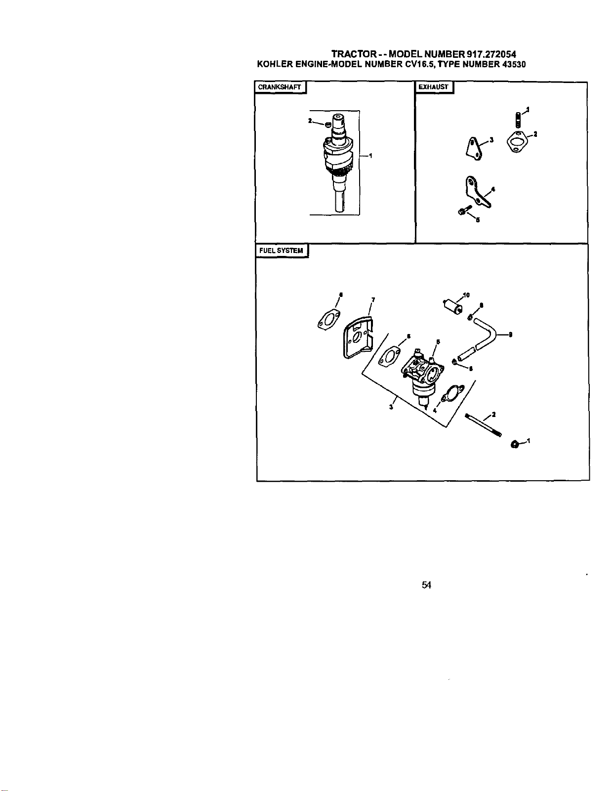
TRACTOR-- MODEL NUMBER 917.272054
KOHLERENGINE-MODELNUMBERCV16.5,TYPE NUMBER43530
CRANKSHAFT ]
'-}
I
I
I --i
EXHAUST I
I r _"_.
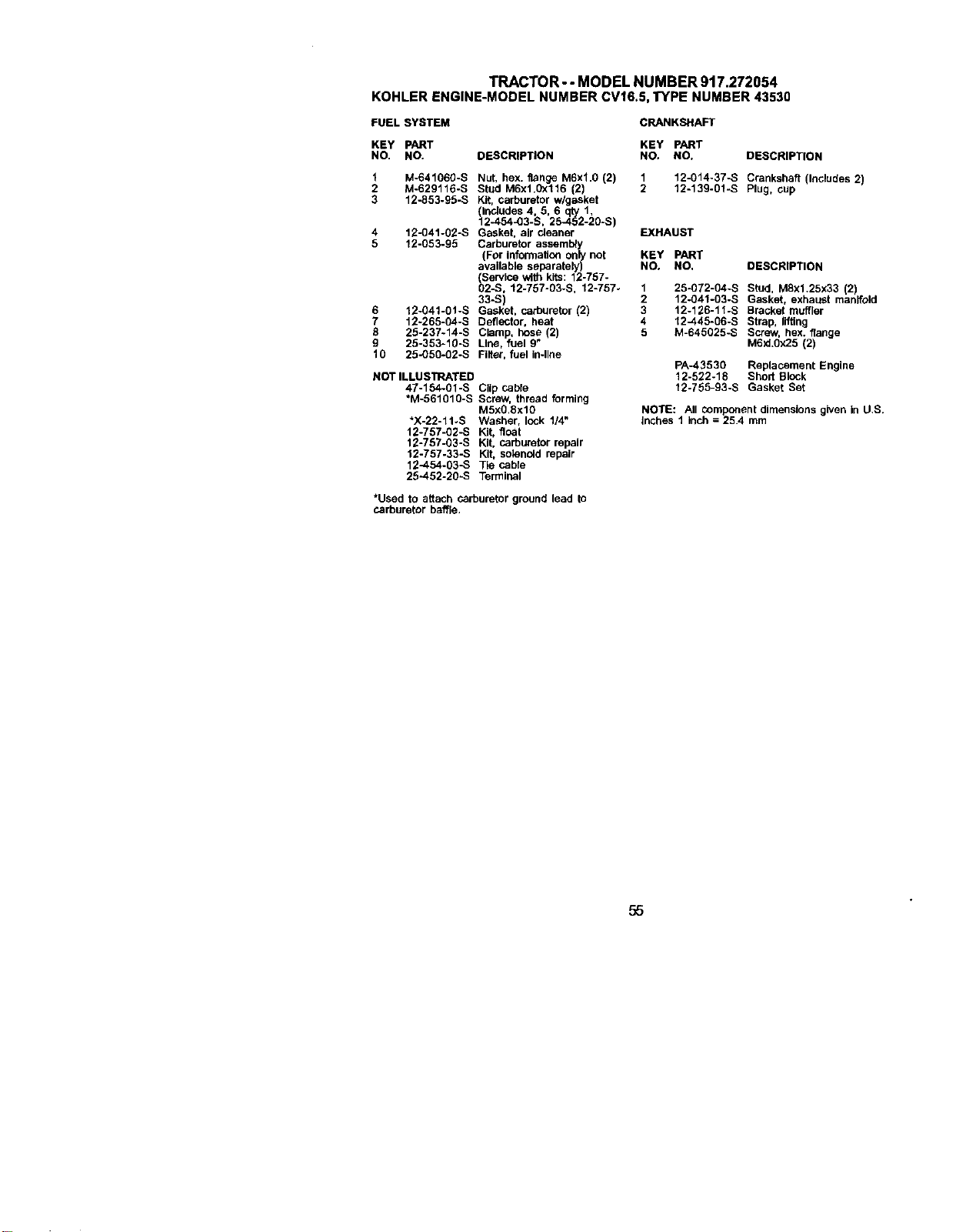
TRACTOR -- MODEL NUMBER 917.272054
KOHLERENGINE-MODELNUMBERCV16.5,TYPE NUMBER43530
FUEL SYSTEM CRANKSHAFT
KEY PART
NO. NO. DESCRIPTION
1 M-641060-S Nut, hex. flange M6xl.0 (2)
2 M-629116-S Stud M6x1.0x116 (2)
3 12-853-95-S Kit, carburetor w/gasket
llnc_udes 4, 5, 6 qty 1,
2-454-03-S, 25-452-20-S)
4 12-041-02-S Gasket, air cleaner
5 12-053-95 Carburetor assembly
(For Infolmallon only not
available separately)
Service with kits: 12-767-
_2-S, 12-757-03-S, 12-757_
33-S)
6 12-041-0t-S Gasket, carburetor (2)
7 12-265-04-S Deflector, heat
8 25-237-14-S Clamp, hose (2)
g 25-353-10-S Ltne, fuel 9"
10 25-050-02-S Filter, fuel in-line
ROT ILLUSTRATED
47-154-01-S Clip cable
*M-561010-S Screw,thread forming
M5X0,Sxl0
*X-22-11_S Washer, lock 1/4"
12o757-02-S Kit, float
12-757-03-S Kg. carburetorrepair
12-757-33-S Kit, sotsnoldrepair
12-454-03-S Tie cable
25-452-20-S Terminal
KEY PART
NO, NO, DESCRIPTION
1 12-014-37-S Crankshaft (Includes 2)
2 12-139-01-S Plug, cup
EXHAUST
KEY PART
NO. NO, DESCRIPTION
1 25-072-04-S Stud, MSxl.25x33 (2
2 12-041-03-S Gasket, exhaus manlfod
3 12-126-11-S Bracket muffler
4 12-445-06-S Strap, IgUng
5 M-645025-S Screw, hex. flange
M6XLOX25 (2)
PA-43530 Replacement Engine
12-522-18 Short Block
12-755-93-S Gasket Set
NOTE: All component dimensions given in U.S.
inches 1 inch = 25.4 mm
*Used to attach carburetor ground lead to
carburetor baffle.
55

56

57

58
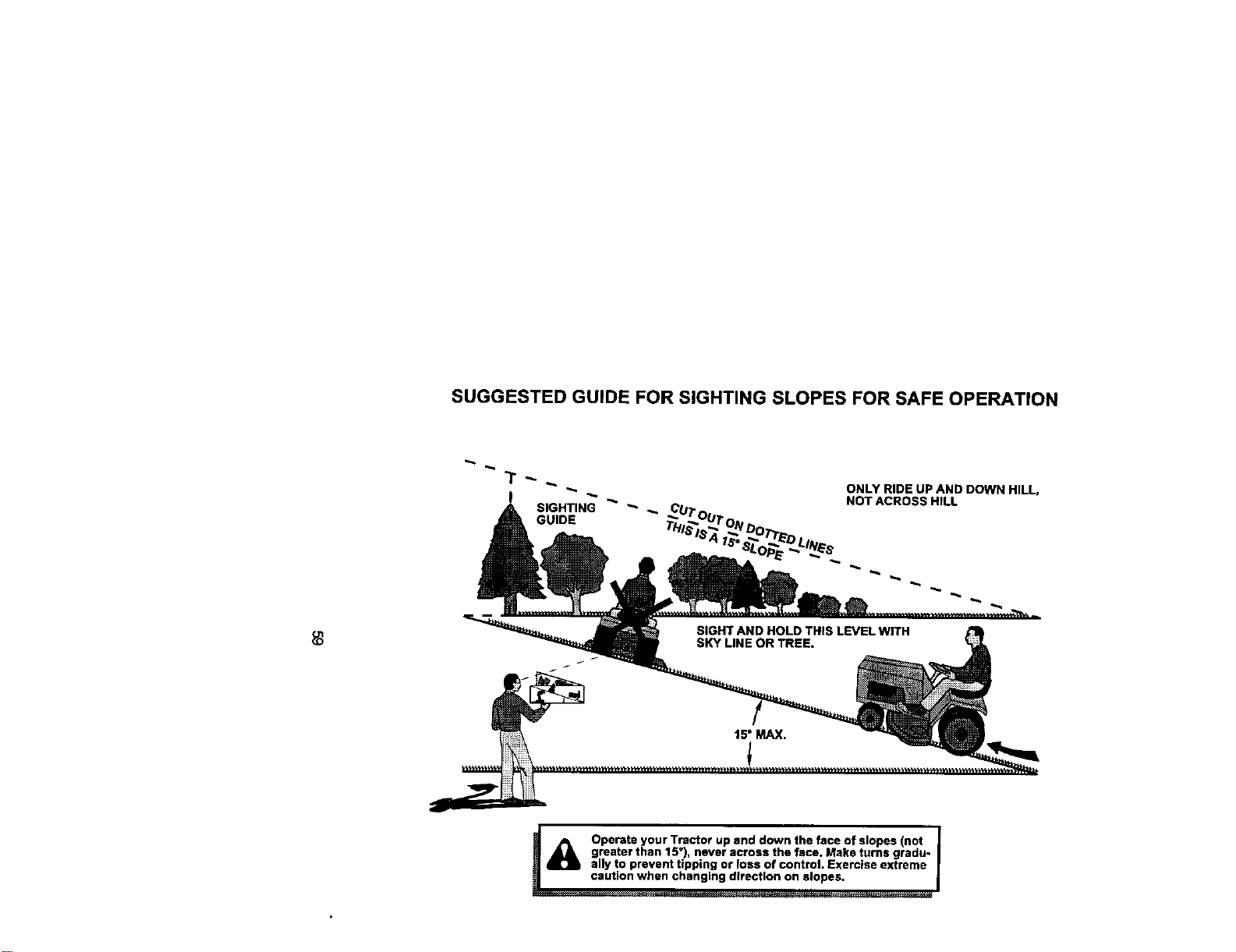
SUGGESTED GUIDE FOR SIGHTING SLOPES FOR SAFE OPERATION
ONLY RIDE UP AND DOWN HILL,
NOT ACROSS HILL
_ Operate your Tractor up and down the face of slopes (not |
I
greater than 15°), never across the face. Make turns gradu-
J
ally to prevent tipping or loss of control. Exercise extreme
Forrepairofmajorbrandappliancesin yourown home..,
nomatterwhomadeit,nomatterwhosoldit!
Forrepairofcam!-inproductslikevacuums,lawnequipment,and
electronics,callforthenearestSearsPartsand RepairCenter.
1-800-488-1222 /_,nylrne,dayornight(U.SA or='y)
www.sear&com
Forthereplacementparts,accessoriesand owner's manuals
thatyou needto do-it-yourse_f,callSearsPartsDlrect'_!
1-800-366-PAR'r 6 a.m.- 11p.m., 7daysaweek
(l._e-3s6-7278) (u.s_.or_
t_,w.sears,com/patsdirect
To purchaseor inquireabouta SearsServiceAgreement
orSearsMaintenanceAgreement:
1-800-827-6655 (U.S.A) 1-800-361-6665 (Canada)
7a.m.- 5 p.m.,CST, Mort.- SaL 9a.m.- 8pJ'n.EST, M - F,4 p.m.Sat.
® Registered Trademark I TM Trademark / s_ Service Mark of Sears, Roebuck and Co.
® Marca Registrada I TM Mama de F_bdca I suMarca de Serviclo de Sears, Roebuck and Co.
MCMarque de commerce / MDMarque d6posee de Sears, Roebuck and Co,
178457 2.20,01 RD Printedin U.S.A.


