
D-Link
®
DGS-1008MP
8-Port 10/100/1000Mbps
Gigabit Ethernet PoE Switch
Manual
Building Networks for People
RECYCLABLE
(Aug. 2015)

D-Link DGS-1008MP Gigabit Ethernet PoE Unmanaged Switch
ii
Information in this document is subject to change without notice.
© 2015 D-Link Corporation. All rights reserved.
Reproduction in any manner whatsoever without the written permission of D-Link Corporation is
strictly forbidden.
Trademarks used in this text: D-Link and the D-LINK logo are trademarks of D-Link Corporation;
Microsoft and Windows are registered trademarks of Microsoft Corporation.
Other trademarks and trade names may be used in this document to refer to either the entities
claiming the marks and names or their products. D-Link Corporation disclaims any proprietary
interest in trademarks and trade names other than its own.
FCC Warning
This equipment has been tested and found to comply with the limits for a Class A digital device,
pursuant to Part 15 of the FCC Rules. These limits are designed to provide reasonable
protection against harmful interference when the equipment is operated in a commercial
environment. This equipment generates, uses, and can radiate radio frequency energy and, if not
installed and used in accordance with this user’s guide, may cause harmful interference to radio
communications. Operation of this equipment in a residential area is likely to cause harmful
interference in which case the user will be required to correct the interference at his own
expense.
CE Mark Warning
This is a Class A product. In a domestic environment, this product may cause radio interference
in which case the user may be required to take adequate measures.
Warnung!
Dies ist ein Produkt der Klasse A. Im Wohnbereich kann dieses Produkt Funkstoerungen
verursachen. In diesem Fall kann vom Benutzer verlangt werden, angemessene Massnahmen
zu ergreifen.
Precaución!
Este es un producto de Clase A. En un entorno doméstico, puede causar interferencias de radio,
en cuyo case, puede requerirse al usuario para que adopte las medidas adecuadas.
Attention!
Ceci est un produit de classe A. Dans un environnement domestique, ce produit pourrait causer
des interférences radio, auquel cas l`utilisateur devrait prendre les mesures adéquates.
Attenzione!
Il presente prodotto appartiene alla classe A. Se utilizzato in ambiente domestico il prodotto può
causare interferenze radio, nel cui caso è possibile che l`utente debba assumere provvedimenti
adeguati.
VCCI Warning
警告使用者:
這是甲類的資訊產品,在居住的環境中使用時,可能會造成射頻干擾,在這種情況下,使用者會
被要求採取某些適當的對策。

CONTENTS
PREFACE ....................................................................................... IV
NOTES, NOTICES, AND CAUTIONS ................................................... IV
SAFETY INSTRUCTIONS .................................................................... V
General Precautions for Rack-Mountable Products .............. viii
INTRODUCTION ........................................................................... 10
SWITCH DESCRIPTION .................................................................. 10
SWITCH FEATURES ....................................................................... 11
Gigabit Ethernet Technology ................................................. 12
D-Link Green Technology ...................................................... 12
FRONT-PANEL COMPONENTS ........................................................ 13
LED Indicators ........................................................................ 13
POWER INPUT ON REAR PANEL ..................................................... 14
INSTALLATION ............................................................................. 16
PACKAGE CONTENTS.................................................................... 16
BEFORE YOU CONNECT TO THE NETWORK .................................... 17
MOUNTING THE SWITCH ON A RACK .............................................. 18
ATTACHING THE RUBBER FEET ..................................................... 19
PROVIDE FOR ADEQUATE VENTILATION ......................................... 19
POWER ON .................................................................................. 20
Power Failure ......................................................................... 20
CONNECTING THE SWITCH ....................................................... 21
CABLE QUALITY............................................................................ 21
CONNECT TO AN END NODE .......................................................... 22
CONNECT TO HUB OR SWITCH ...................................................... 23
CONNECT TO NETWORK BACKBONE OR SERVER ............................ 24
TECHNICAL SPECIFICATIONS ................................................... 25
GLOSSARY ................................................................................... 28
D-Link DGS-1008MP Gigabit Ethernet PoE Unmanaged Switch
iv
Preface
The DGS-1008MP Manual is divided into sections that describe the
system installation and operating instructions with examples.
Section 1, Introduction - A description of the physical features of
the Switch, including LED indicators, ports and panel descriptions.
Section 2, Installation – A description of the physical installation of
the Switch, mounting the Switch in an equipment rack and powering
on the Switch.
Section 3, Connecting the Switch – A description of how to
connect your Switch to an end node, hub, another switch or
backbone server.
Appendix Technical Specifications - The technical specifications
of the DGS-1008MP.
Notes, Notices, and Cautions
NOTE:
A NOTE indicates important information
that helps you make better use of your device.
NOTICE:
A NOTICE indicates either potential
damage to hardware or loss of data and tells you
how to avoid the problem.
CAUTION: A CAUTION indicates the potential for
property damage, personal injury or death.

D-Link DGS-1008MP Gigabit Ethernet PoE Unmanaged Switch
v
Safety Instructions
Use the following safety guidelines to ensure your own personal safety and to help protect your
system from potential damage. Throughout this safety section, the caution icon ( ) is used to
indicate cautions and precautions that you need to review and follow.
Safety Cautions
To reduce the risk of bodily injury, electrical shock, fire, and damage to the
equipment, observe the following precautions.
Observe and follow service markings. Do not service any product except as
explained in your system documentation. Opening or removing covers that are
marked with the triangular symbol with a lightning bolt may expose you to an
electrical shock. Only a trained service technician should service components inside
these compartments.
If any of the following conditions occur, unplug the product from the electrical outlet
and replace the part or contact your trained service provider:
– The power cable, extension cable, or plug is damaged.
– An object has fallen into the product.
– The product has been exposed to water.
– The product has been dropped or damaged.
– The product does not operate correctly when you follow the operating
instructions.
•
Keep your system away from radiators and heat sources. Also, do not block
cooling vents.
•
Do not place any device on top of Switch, or place the Switch on top of any
device or object that will block the free flow of air through the ventilation slots on
the sides, top, and bottom of the Switch’s case.
•
Keep your hand away from top and bottom of device that generates a significant
amount of heat.
•
Do not spill food or liquids on your system components, and never operate the
product in a wet environment. If the system gets wet, see the appropriate
section in your troubleshooting guide or contact your trained service provider.
•
Do not push any objects into the openings of your system. Doing so can cause
a fire or an electric shock by shorting out interior components.
•
Use the product only with approved equipment.
•
Allow the product to cool before removing covers or touching internal
components.

D-Link DGS-1008MP Gigabit Ethernet PoE Unmanaged Switch
vi
•
Operate the product only from the type of external power source indicated on
the electrical ratings label. If you are not sure of the type of power source
required, consult your service provider
or local power company.

D-Link DGS-1008MP Gigabit Ethernet PoE Unmanaged Switch
vii
Safety Instructions (continued)
•
To help avoid damaging your system, be sure the voltage selection Switch (if
provided) on the power supply is set to match the power available at your
location:
– 115 volts (V)/60 hertz (Hz) in most of North and South America and
some Far Eastern countries such as South Korea and Taiwan
– 100 V/50 Hz in eastern Japan and 100 V/60 Hz in western Japan.
– 230 V/50 Hz in most of Europe, the Middle East, and the Far East.
•
Also be sure that attached devices are electrically rated to operate with the
power available in your location.
•
Use only approved power cable(s). If you have not been provided with a power
cable for your system or for any AC-powered option intended for your system,
purchase a power cable that is approved for use in your country. The power
cable must be rated for the product and for the voltage and current marked on
the product's electrical ratings label. The voltage and current rating of the cable
should be greater than the ratings marked on the product.
•
To help prevent an electric shock, plug the system and peripheral power cables
into properly grounded electrical outlets. These cables are equipped with three-
prong plugs to help ensure proper grounding. Do not use adapter plugs or
remove the grounding prong from a cable. If you must use an extension cable,
use a 3-wire cable with properly grounded plugs.
•
Observe extension cable and power strip ratings. Make sure that the total
ampere rating of all products plugged into the extension cable or power strip
does not exceed 80 percent of the ampere ratings limit for the extension cable
or power strip.
•
To help protect your system from sudden, transient increases and decreases in
electrical power, use a surge suppressor, line conditioner, or uninterruptible
power supply (UPS).
•
Position system cables and power cables carefully; route cables so that they
cannot be stepped on or tripped over. Be sure that nothing rests on any cables.
•
Do not modify power cables or plugs. Consult a licensed electrician or your
power company for site modifications. Always follow your local/national wiring
rules.
•
When connecting or disconnecting power to hot-pluggable power supplies, if
offered with your system, observe the following guidelines:
– Install the power supply before connecting the power cable to the power
supply.
– Unplug the power cable before removing the power supply.
– If the system has multiple sources of power, disconnect power from the
system by unplugging all power cables from the power supplies.
•
Move products with care; ensure that all casters and/or stabilizers are firmly
connected to the system. Avoid sudden stops and uneven surfaces.
D-Link DGS-1008MP Gigabit Ethernet PoE Unmanaged Switch
viii
Safety Instructions (continued)
General Precautions for Rack-
Mountable Products
•
Observe the following precautions for rack stability and safety. Also refer to the
rack installation documentation accompanying the system and the rack for
specific caution statements and procedures.
•
Systems are considered to be components in a rack. Thus, "component" refers
to any system as well as to various peripherals or supporting hardware.
CAUTION: Installing systems in a rack without the front
and side stabilizers installed could cause the rack to tip
over, potentially resulting in bodily injury under certain
circumstances. Therefore, always install the stabilizers
before installing components in the rack.
After installing system/components in a rack, never pull
more than one component out of the rack on its slide
assemblies at one time. The weight of more than one
extended component could cause the rack to tip over
and may result in serious injury.
•
Before working on the rack, make sure that the stabilizers are secured to the
rack, extended to the floor, and that the full weight of the rack rests on the floor.
Install front and side stabilizers on a single rack or front stabilizers for joined
multiple racks before working on the rack.
D-Link DGS-1008MP Gigabit Ethernet PoE Unmanaged Switch
ix
Safety Instructions (continued)
•
Always load the rack from the bottom up, and load the heaviest item in the rack
first.
•
Make sure that the rack is level and stable before extending a component from
the rack.
•
Use caution when pressing the component rail release latches and sliding a
component into or out of a rack; the slide rails can pinch your fingers.
•
After a component is inserted into the rack, carefully extend the rail into a locking
position, and then slide the component into the rack.
•
Do not overload the AC supply branch circuit that provides power to the rack.
The total rack load should not exceed 80 percent of the branch circuit rating.
•
Ensure that proper airflow is provided to components in the rack.
•
Do not step on or stand on any component when servicing other components in
a rack.
CAUTION:
Never defeat the ground conductor or
operate the equipment in the absence of a suitably
installed ground conductor. Contact the appropriate
electrical inspection authority or an electrician if you are
uncertain that suitable grounding is available.
CAUTION:
The system chassis must be positively
grounded to the rack cabinet frame. Do not attempt to
connect power to the system until grounding cables are
connected. Completed power and safety ground wiring
must be inspected by a qualified electrical inspector.
An energy hazard will exist if the safety ground cable is
omitted or disconnected.

SECTION 1
Introduction
Switch Description
Switch Features
Gigabit Ethernet Technology
D-Link Green Technology
Front-Panel Components
LED Indicators
Power Input on Rear Panel
Switch Description
The DGS-1008MP Switch provides 8 Gigabit Ethernet ports, of which 8
ports supporting Power over Ethernet (PoE) for PoE applications such
as wireless Access Points (APs), IP cameras, and IP phones With wire-
speed Gigabit capacity, DGS-1008MP provides non-blocking switching
for both home and office environment.
IEEE 802.3af/at Power over Ethernet
All ports of the DGS-1008MP support the IEEE 802.3af/at PoE protocol.
Each port can supply up to 30 watts power to the IEEE 802.3af/at-
compliant Powered Device (PD) directly. It minimizes the clutter of extra
cables making the network deployment more easily especially when
device are far from power outlets.
Easy to Use, Safe and Excellent Performance
DGS-1008MP is a Plug-and-Play device that requires no configuration.
It supports auto-MDI/MDI-X on all ports, and eliminates the need of
crossover cables for connection to another switches or hubs. Auto-
Negotiation on each port senses the link speed (either 10, 100 or
1000M) of a network device and intelligently adjusts the compatibility
and optimal performance. Fanless design extends the product life time
and also reduces the noise when operating.

DGS-1008MP features many safety functions to prevent the
unexpected overloading of the PoE power. The Switch will cut off the
power feed immediately when any error is detected, protecting both the
PoE device and the Switch from damage.
The Gigabit PoE ports provide a larger bandwidth for high speed
network applications, especially IEEE802.11n AP, high resolution video
cameras, and phones. Combining the convenience of PoE, superior
performance, and ease of use, DGS-1008MP is the ideal PoE solution
for both home and small business networks.
Switch Features
The DGS-1008MP 8-Port 10/100/1000Mbps PoE Switch does not
require any management. It’s designed for easy installation, flexibility
and high performance. Connect devices to the Switch as the scale and
volume of network traffic increases.
•
8 × 10/100/1000Mbps Auto-negotiation Gigabit Ethernet RJ45
ports with 8 port PoE function
•
Supports PoE power up to 30W for each PoE port
•
Supports PoE budget up to 140W
•
Supports PoE IEEE802.3af and IEEE802.3at compliant Powered
Device (PD)
•
Supports IEEE802.3x flow control for Full-duplex Mode and
backpressure for Half-duplex Mode
•
Store and Forward Switching Method
•
Auto Negotiation on Duplex Mode
•
Auto MDI/MDIX supported
•
Support Full/Half Duplex Transfer Mode on 10/100 Mbps
•
Support Full Duplex Transfer Mode on 1000 Mbps
•
Wire-Speed reception and transmission
•
8K absolute MAC Address
•
Jumbo Frame support (9216Bytes)

Gigabit Ethernet Technology
Gigabit Ethernet is an extension of IEEE 802.3 Ethernet utilizing the
same packet structure, format, and support for CSMA/CD protocol, full
duplex, flow control, and management objects, but with a tenfold
increase in theoretical throughput over 100-Mbps Fast Ethernet and a
hundredfold increase over 10-Mbps Ethernet. Since it is compatible
with all 10-Mbps and 100-Mbps Ethernet environments, Gigabit
Ethernet provides a straightforward upgrade without wasting a
company’s existing investment in hardware, software and trained
personnel.
The increased speed and extra bandwidth offered by Gigabit Ethernet
is necessary to coping with the network bottlenecks; more computers
and their bus speeds getting faster, and more applications generate
more traffic in the network. Upgrading key components, such as your
backbone and servers to Gigabit Ethernet can greatly improve network
response times as well as significantly speed up the traffic between
your subnets.
Gigabit Ethernet supports video conferencing, complex imaging and
similar data-intensive applications. Likewise, since data transfers occur
10 times faster than Fast Ethernet, servers outfitted with Gigabit
Ethernet NIC’s are able to perform 10 times the number of operations in
the same amount of time.
D-Link Green Technology
•
IEEE 802.3az Energy-Efficient Ethernet (EEE):
It is the first standard in the history of Ethernet to address
proactive reduction in energy consumption for networked devices
.
The IEEE 802.3 EEE standard defines mechanisms and
protocols intended to reduce the energy consumption of network
links during periods of low utilization, by transitioning interfaces
into a low-power state without interrupting the network connection.
•
Power saving by link status.
If there is no link on a port, such as when there is no computer
connected to the port or the connected computer is powered off,
D-Link’s Green Technology will enter a "sleep mode", drastically
reducing power used for that port.
•
Power saving by cable length: 0~20m, 21~100m.
D-Link’s Green Technology detects the length of connected
Ethernet cable and adjusts power usage accordingly without
affecting performance. This way, a port connected to a 20m cable
only uses as much power as it needs, instead of using full power,
which is only needed for 100m cables.
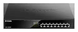
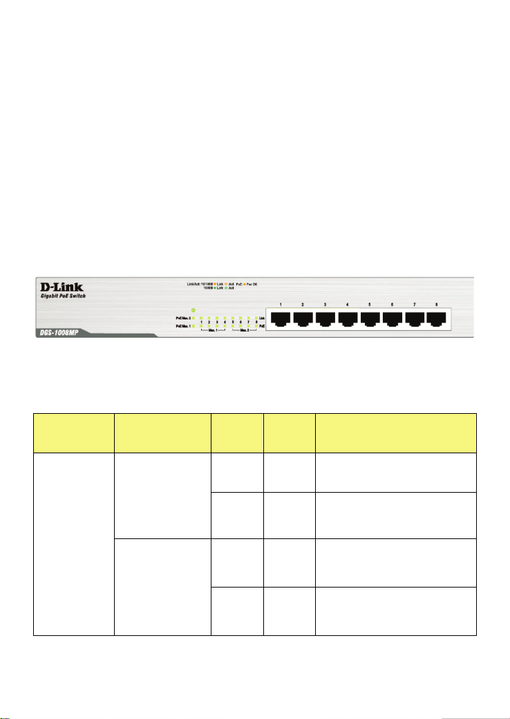
Front-Panel Components
On the front panel of the Switch you will see the following.
•
LED status indicators
•
8 Auto-Negotiating 10/100/1000Mbps PoE ports on the DGS-
1008MP
Front Panel View of the Switch
LED Indicators
Location
LED
Indicative
Color Status Description
Per Device
Power
Green
Solid
Light
Power On
Off
Light
Off
Power Off
PoE Max. 1
(port 1~4)
Amber
Light
On
PD device insert and
power feeding over
maximum PoE budget
Off
Light
Off
No PD device insert or
PD insert and power
feeding

PoE Max. 2
(port 5~8)
Amber
Light
On
PD device insert and
power feeding over
maximum PoE budget
Off
Light
Off
No PD device insert or
PD insert and power
feeding
LED Per
10/100/1000
Mbps Port
Link/Act/Speed
Green
Solid
Green
When there is a secure
1000Mbps connection at
the port.
Blinking
Blinking
Green
When there is reception
or transmission occurring
at the port.
Amber
Solid
Amber
When there is a secure
10/100Mbps connection
at the port.
Blinking
Blinking
Amber
When there is reception
or transmission occurring
at the port.
Off
Light
off
No link
LED Per
PoE Port
Pwr OK
Amber
Light
On
PD device insert and
power feeding
Off
Light
Off
No PD device insert
Power Input on Rear Panel
The power cable connection is located on the rear panel of the Switch.

Rear panel view of the Switch
Switch power input is provided by and internal universal power supply
(100-240VAC, 50-60Hz).
The AC power connector is a standard three-pronged connector that
supports the power cord. Please see the Power On section below for
instructions on how to properly connect the Switch to a power source.

SECTION 2
Installation
Package Contents
Before You Connect to the Network
Installing the Switch
Power On
Package Contents
Open the shipping carton of the Switch and carefully unpack its contents.
The carton should contain the following items:
•
One DGS-1008MP 8-Port 10/100/1000BASE-T Gigabit Ethernet
PoE Unmanaged Switch
•
Four rubber feet with adhesive backing
•
One power Cord
•
Mounting ears for rack-mounting
•
Quick Install Guide
If any item is found missing or damaged, please contact your local D-Link
reseller for replacement.

Before You Connect to the Network
The site where you install the Switch may greatly affect its performance.
Please follow these guidelines for setting up the Switch.
•
Install the Switch on a sturdy, level surface that can support at
least 3 kg (6.6 lbs) of weight. Do not place heavy objects on the
Switch.
•
The power outlet should be within 1.82 meters (6 feet) of the
Switch.
•
Visually inspect the power cord and see that it is fully secured to
the AC power port.
•
Make sure that there is adequate space for proper heat
dissipation from and adequate ventilation around the Switch.
Leave at least 10 cm (4 inches) of space at the front and rear of
the Switch for ventilation.
•
Do not place any device on top of Switch, or place the Switch on
top of any device or object that will block the free flow of air
through the ventilation slots on the sides, top, and bottom of the
Switch’s case.
•
Keep your hand away from top and bottom of device that
generates a significant amount of heat.
•
Install the Switch in a fairly cool and dry place for the acceptable
temperature and humidity operating ranges.
•
Install the Switch in a site free from strong electromagnetic field
generators (such as motors), vibration, dust, and direct exposure
to sunlight.
•
When installing the Switch on a level surface, attach the rubber
feet to the bottom of the device. The rubber feet cushion the
Switch, protect the casing from scratches and prevent it from
scratching other surfaces.
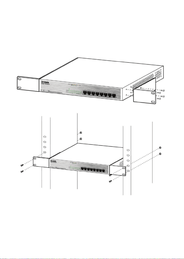
Mounting the Switch on a Rack
The DGS-1008MP can easily be mounted on a rack. Two mounting
ears are provided for this purpose. Make sure that the front panel is
exposed in order to view the LEDs. Please refer to the following
illustrations:
Mounting the Switch to a Rack
1. Attach the ears to each side of the Switch, using the screw-holes
located on the side of the device.
2. Firmly attach the ears to the rack as shown. Please follow the usual
safety precautions for rack-mountable products
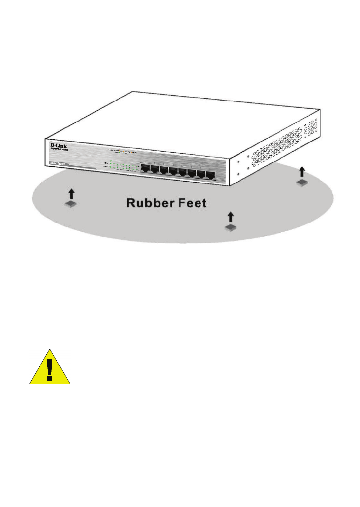
Attaching the Rubber Feet
Use rubber feet provided. Position and apply rubber feet to the
underside of the DGS-1008MP Switch.
Attaching the Rubber Feet
Provide for Adequate Ventilation
CAUTION: Do not place any device on top of Switch, or
place the Switch on top of any device or object that will
block the free flow of air through the ventilation slots on
the sides, top, and bottom of the Switch’s case. In
addition, care should be taken not to locate the Switch
next to, on top of, or underneath any device that
generates a significant amount of heat. For the Switch to
perform at its opti
mal level, the Switch must have
adequate ventilation to prevent the Switch from
overheating and becoming damaged.

Power On
To power on the Switch, Plug-in the female connector of the provided
power cord into this socket, and the male side of the cord into a suitable
power source.
After the Switch is powered on, the LED indicators will blink briefly while
the system resets.
Power Failure
As a precaution, in the event of a power failure, unplug the Switch.
When power is resumed, plug the Switch back in.
Section 3
Connecting the Switch
Switch to End Node
Switch to Hub or Switch
Connecting to a Server
NOTE: All Ethernet ports auto-detect MDI
/MDIX, port
speed (10, 100, 1000Mbps) and duplex of the device
connected to the Switch.
Cable Quality
For all connections to the Switch, use these rules to determine the
•
For connections to 10BASE-T and 100BASE-TX devices, use
Category 5 or 5e UTP/STP cable.
•
For connections to 100BASE-TX and 1000BASE-T devices, use
Category 5e or better UTP/STP cable. All 1000BASE-T
connections operate in full duplex mode.
NOTE: UTP (Unshielded Twisted Pair) Ethernet cabling
is adequate for most small office environments. More
expensive STP (Shielded Twisted Pair) can also be
used, but is generally only needed where there will be
risk of strong Electromagnetic of Radio Frequency
Interference.
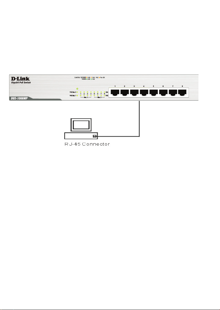
Connect to an End Node
End nodes include PCs outfitted with a 10, 100 or 1000 Mbps RJ-45
Ethernet/Fast Ethernet Network Interface Card (NIC) and Ethernet
ready routers. Use standard Ethernet cable to connect the Switch to
end nodes. Switch ports will automatically adjust to the hardware
characteristics (MDI/MDIX, speed, duplex) of the device to which it is
connected.
Switch connected to an end node
Observe the guidelines for cable quality stated at the beginning of this
section. The Link/Act/Speed LEDs for each port lights green when the
link is valid.
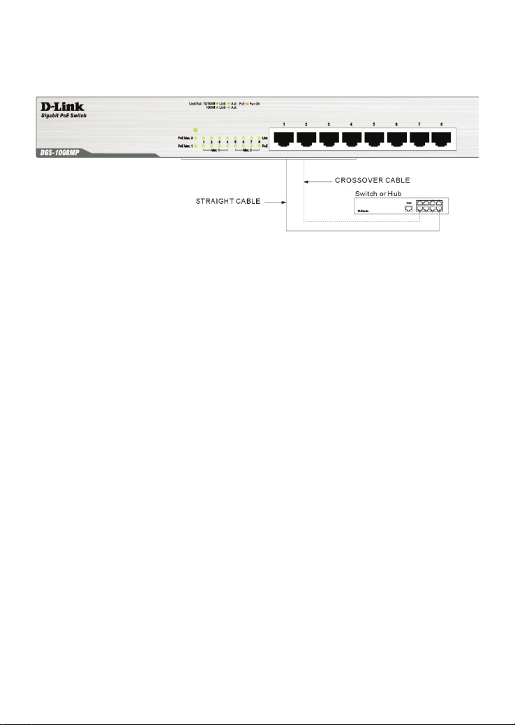
Connect to Hub or Switch
Connect to another switch or hub
Observe the guidelines for cable quality stated at the beginning of this
section. The Link/Act/Speed LEDs for each port lights green when the
link is valid.
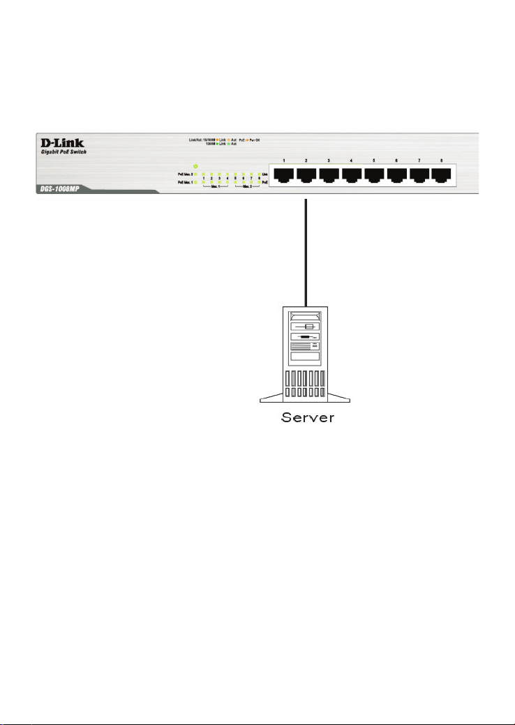
Connect to Network Backbone or Server
Any port may be used to uplink the Switch to a network backbone or
network server. When linking to a 1000BASE-T device the port
operates in full duplex mode.
Connection to a Server
Observe the guidelines for cable quality stated at the beginning of this
section. The Link/Act/Speed LEDs for each port lights green when the
link is valid.

Appendix
Technical Specifications
General
Standards: IEEE 802.3 10BASE-T
IEEE 802.3u compliance
IEEE 802.3ab compliance
IEEE 802.3x Flow Control supports for Full Duplex
IEEE 802.3af/at
Protocol: CSMA/CD
Data Transfer
Rate:
Ethernet: 10Mbps (Half-duplex)
20Mbps (Full-duplex)
Fast
Ethernet:
100Mbps (Half-duplex)
200Mbps (Full-duplex)
Gigabit
Ethernet:
2000Mbps (Full-duplex)
Topology: Star
Network Cables: Ethernet: 2-pair UTP Cat.3/4/5/5e, Unshield
Twisted Pair (UTP )Cable
Fast
Ethernet:
2-pair UTP Cat.5/5e,
Unshield Twisted Pair (UTP )Cable
Gigabit
Ethernet:
4-pair UTP Cat.5/ 5e,
Unshield Twisted Pair (UTP )Cable
Number of Ports: Eight (8) 10/100/1000BASE-T Gigabit Ethernet
ports
PoE Port Port 1 ~8
PoE Budget 140Watts

Physical and Environmental
AC Inputs:
100~240VAC; 50-60Hz, 0.4A Max.
Internal universal power supply
Power Consumption: DGS-1008MP: 13.5 W (PoE off), 151 W (PoE On)
Fan Fan-less
Operating
Temperature:
32°F ~ 104F ° (0 °C ~ 40 ºC)
Storage Temperature:
14°F ~ 158°F (-10°C ~ 70°C)
Operation Humidity: 10% ~ 90% RH, non-condensing
Storage Humidity: 5% ~ 90% RH, non-condensing
Dimensions
(W x D x H)
11.02 in. x 7.09 in. x 1.73 in.
(280 mm x 180 mm x 44 mm)
Weight DGS-1008MP: 1.8274 kg
EMI
FCC Class A, CE Class A, VCCI Class A,
ICES-003 Class A, RCM, BSMI, CCC
Safety: cUL, CB, CE LVD, BSMI, CCC

Performance
Transmission Method: Store-and-forward
RAM Buffer: 128KBytes per device
Filtering Address
Table:
8K MAC address per device
Packet Filtering/
Forwarding Rate:
Full wire speed
MAC Address
Learning:
Self-learning, auto-aging
Jumbo Frame
9216Bytes support

Glossary
1000BASE-T –1000BASE-T - Known as IEEE 802.3ab which is a standard for
Gigabit Ethernet over copper wiring.
100BASE-TX – 100Mbps Ethernet implementation over Category 5 and Type 1
Twisted Pair cabling.
10BASE-T – The IEEE 802.3 specification for Ethernet over Unshielded Twisted
Pair (UTP) cabling.
aging – The automatic removal of dynamic entries from the Switch Database which
have timed-out and are no longer valid.
ATM – Asynchronous Transfer Mode. A connection oriented transmission protocol
based on fixed length cells (packets). ATM is designed to carry a complete range of
user traffic, including voice, data, and video signals.
Auto-Negotiation – A feature on a port, which allows it to advertise its capabilities
for speed, duplex, and flow control. When connected to an end station that also
supports auto-negotiation, the link can self-detect its optimum operating setup.
Backbone port – A port that does not learn device addresses, and that receives all
frames with an unknown address. Backbone ports are normally used to connect the
Switch to the backbone of your network. Note that backbone ports were formerly
known as designated downlink ports.
Backbone – The part of a network used as the primary path for transporting traffic
between network segments.
Bandwidth – Information capacity, measured in bits per second, that a channel can
transmit. The bandwidth of Ethernet is 10Mbps. the bandwidth of Fast Ethernet is
100Mbps.
Baud rate – The switching speed of a line. Also known as line speed.
BOOTP – The BOOTP protocol allows you to automatically map an IP address to a
given MAC address each time a device is started. In addition, the protocol can
assign the subnet mask and default gateway to a device.
Bridge – A device that interconnects local or remote networks no matter what higher
level protocols are involved. Bridges form a single logical network, centralizing
network administration.
Broadcast – A message sent to all destination devices on the network.
Broadcast Storm – Multiple simultaneous broadcasts that typically absorb available
network bandwidth and can cause network failure.
Console port – The port on the Switch accepting a terminal or modem connector. It
changes the parallel arrangement of data within computers to the serial form used
on data transmission links. This port is most often used for dedicated local
management.
CSMA/CD – Channel access method used by Ethernet and IEEE 802.3 standards,
in which devices transmit only after finding the data channel clear for some period of

time. When two devices transmit simultaneously, a collision occurs and the colliding
devices delay their retransmissions for a random amount of time.
Data Center Switching – The point of aggregation within a corporate network
where a switch provides high-performance access to server farms, a high-speed
backbone connection, and a control point for network management and security.
Ethernet – A LAN specification developed jointly by Xerox, Intel, and Digital
Equipment Corporation. Ethernet networks operate at 10Mbps using CSMA/CD to
run over cabling.
Fast Ethernet – 100Mbps technology based on the Ethernet/CD network access
method.
Flow Control – (IEEE 802.3z) A means of holding packets back at the transmit port
of the connected end station. Prevents packet loss at a congested switch port.
Forwarding – The process of sending a packet toward its destination by an
internetworking device.
Full-duplex – A system that allows packets to be transmitted and received at the
same time and, in effect, doubles the potential throughput of a link.
Half-duplex – A system that allows packets to be transmitted and received, but not
at the same time. Contrast with full-duplex.
IP address – Internet Protocol address. A unique identifier for a device attached to a
network using TCP/IP. The address is written as four octets separated with full-stops
(periods), and is made up of a network section, an optional subnet section and a
host section.
IPX – Internetwork Packet Exchange. A protocol allowing communication in a
NetWare network.
LAN – Local Area Network. A network of connected computing resources (such as
PCs, printers, servers) covering a relatively small geographic area (usually not larger
than a floor or building). Characterized by high data rates and low error rates.
Latency – The delay between the time a device receives a packet and the time the
packet is forwarded out of the destination port.
Line speed – See baud rate.
Main port – The port in a resilient link that carries data traffic in normal operating
conditions.
MDI – Medium Dependent Interface. An Ethernet port connection where the
transmitter of one device is connected to the receiver of another device.
MDIX – Medium Dependent Interface Cross-over. An Ethernet port connection
where the internal transmit and receive lines are crossed.
MIB – Management Information Base. Stores a device’s management
characteristics and parameters. MIBs are used by the Simple Network Management
Protocol (SNMP) to contain attributes of their managed systems. The Switch
contains its own internal MIB.
Multicast – Single packets copied to a specific subset of network addresses. These
addresses are specified in the destination-address field of the packet.
Protocol – A set of rules for communication between devices on a network. The
rules dictate format, timing, sequencing, and error control.

Rresilient Llink – A pair of ports that can be configured so that one will take over
data transmission should the other fail. See also main port and standby port.
RJ-45 – Standard 8-wire connectors for IEEE 802.3 10BASE-T networks.
RMON – Remote Monitoring. Subset of SNMP MIB II, which allows monitoring and
management capabilities by addressing up to ten different groups of information.
RPS – Redundant Power System. A device that provides a backup source of power
when connected to the Switch.
Server Farm – A cluster of servers in a centralized location serving a large user
population.
SLIP – Serial Line Internet Protocol. A protocol that allows IP to run over a serial line
connection.
SNMP – Simple Network Management Protocol. A protocol originally designed to be
used in managing TCP/IP internets. SNMP is presently implemented on a wide
range of computers and networking equipment and may be used to manage many
aspects of network and end station operation.
Spanning Tree Protocol – (STP) A bridge-based system for providing fault
tolerance on networks. STP works by allowing you to implement parallel paths for
network traffic, and to ensure that redundant paths are disabled when the main
paths are operational and enabled if the main paths fail.
Stack – A group of network devices that are integrated to form a single logical
device.
Standby port – The port in a resilient link that will take over data transmission if the
main port in the link fails.
Switch – A device that filters, forwards, and floods packets based on the packet’s
destination address. The Switch learns the addresses associated with each switch
port and builds tables based on this information to be used for the switching decision.
TCP/IP – A layered set of communications protocols providing Telnet terminal
emulation, FTP file transfer, and other services for communication among a wide
range of computer equipment.
Telnet – A TCP/IP application protocol that provides virtual terminal service, letting a
user log in to another computer system and access a host as if the user were
connected directly to the host.
TFTP – Trivial File Transfer Protocol. Allows you to transfer files (such as software
upgrades) from a remote device using your switch’s local management capabilities.
UDP – User Datagram Protocol. An Internet standard protocol that allows an
application program on one device to send a datagram to an application program on
another device.
VLAN – Virtual LAN. A group of location- and topology-independent devices that
communicate as if they are on a common physical LAN.
VLT – Virtual LAN Trunk. A Switch-to-Switch link which carries traffic for all the
VLANs on each Switch.
VT100 – A type of terminal that uses ASCII characters. VT100 screens have a text-
based appearance.