
xStack® DGS-3420 Series Layer 2 Managed Stackable Gigabit Switch Web UI Reference Guide
i
Information in this document is subject to change without notice.
© 2013 D-Link Corporation. All rights reserved.
Reproduction of this document in any manner whatsoever without the written permission of D-Link Corporation is strictly forbidden.
Trademarks used in this text: D-Link and the D-LINK logo are trademarks of D-Link Corporation; Microsoft and Windows are registered trademarks of
Microsoft Corporation.
Other trademarks and trade names may be used in this document to refer to either the entities claiming the marks and names or their products. D-
Link Corporation disclaims any proprietary interest in trademarks and trade names other than its own.
February, 2013 P/N 651GS3420035G

xStack® DGS-3420 Series Layer 2 Managed Stackable Gigabit Switch Web UI Reference Guide
ii
Table of Contents
Intended Readers ............................................................................................................................................................ 1
Typographical Conventions ............................................................................................................................................. 1
Notes, Notices and Cautions........................................................................................................................................... 1
Safety Instructions ........................................................................................................................................................... 1
Safety Cautions ........................................................................................................................................................... 2
General Precautions for Rack-Mountable Products........................................................................................................ 3
Protecting Against Electrostatic Discharge ..................................................................................................................... 4
Chapter 1 Web-based Switch Configuration ...................................................................................... 5
Introduction ...................................................................................................................................................................... 5
Login to the Web Manager .............................................................................................................................................. 5
Web-based User Interface .............................................................................................................................................. 5
Areas of the User Interface.......................................................................................................................................... 6
Web Pages ...................................................................................................................................................................... 6
Chapter 2 System Configuration ......................................................................................................... 8
Device Information .......................................................................................................................................................... 8
System Information Settings ........................................................................................................................................... 9
Port Configuration ......................................................................................................................................................... 10
DDM ........................................................................................................................................................................... 10
Port Settings .............................................................................................................................................................. 17
Port Description Settings ........................................................................................................................................... 18
Port Error Disabled .................................................................................................................................................... 19
Port Media Type ........................................................................................................................................................ 20
Port Auto Negotiation Information ............................................................................................................................. 20
Jumbo Frame Settings .............................................................................................................................................. 21
EEE Settings ............................................................................................................................................................. 22
PoE ................................................................................................................................................................................ 23
PoE System Settings ................................................................................................................................................. 24
PoE Port Settings ...................................................................................................................................................... 26
Serial Port Settings ....................................................................................................................................................... 27
Warning Temperature Settings ..................................................................................................................................... 27
System Log configuration .............................................................................................................................................. 28
System Log Settings .................................................................................................................................................. 28
System Log Server Settings ...................................................................................................................................... 28
System Log ................................................................................................................................................................ 29
System Log & Trap Settings ...................................................................................................................................... 30
System Severity Settings ........................................................................................................................................... 31
Time Range Settings ..................................................................................................................................................... 32
Port Group Settings ....................................................................................................................................................... 32
Time Settings ................................................................................................................................................................ 33
User Accounts Settings ................................................................................................................................................. 33
Command Logging Settings .......................................................................................................................................... 35
Stacking ......................................................................................................................................................................... 35
Stacking Device Table ............................................................................................................................................... 37
Stacking Mode Settings ............................................................................................................................................. 37

xStack® DGS-3420 Series Layer 2 Managed Stackable Gigabit Switch Web UI Reference Guide
iii
Chapter 3 Management ...................................................................................................................... 39
ARP ............................................................................................................................................................................... 39
Static ARP Settings ................................................................................................................................................... 39
Proxy ARP Settings ................................................................................................................................................... 40
ARP Table ................................................................................................................................................................. 40
Gratuitous ARP ............................................................................................................................................................. 41
Gratuitous ARP Global Settings ................................................................................................................................ 41
Gratuitous ARP Settings ............................................................................................................................................ 42
IPv6 Neighbor Settings ................................................................................................................................................. 42
IP Interface .................................................................................................................................................................... 43
System IP Address Settings ...................................................................................................................................... 44
Interface Settings ....................................................................................................................................................... 45
Loopback Interface Settings ...................................................................................................................................... 49
Management Settings ................................................................................................................................................... 50
Out of Band Management Settings ............................................................................................................................... 51
Session Table................................................................................................................................................................ 52
Single IP Management .................................................................................................................................................. 52
Single IP Settings ...................................................................................................................................................... 53
Topology .................................................................................................................................................................... 54
Firmware Upgrade ..................................................................................................................................................... 61
Configuration File Backup/Restore ............................................................................................................................ 61
Upload Log File ......................................................................................................................................................... 62
SNMP Settings .............................................................................................................................................................. 62
SNMP Global Settings ............................................................................................................................................... 63
SNMP Traps Settings ................................................................................................................................................ 64
SNMP Linkchange Traps Settings ............................................................................................................................ 64
SNMP View Table Settings ....................................................................................................................................... 65
SNMP Community Table Settings ............................................................................................................................. 66
SNMP Group Table Settings ..................................................................................................................................... 67
SNMP Engine ID Settings ......................................................................................................................................... 68
SNMP User Table Settings........................................................................................................................................ 69
SNMP Host Table Settings ........................................................................................................................................ 70
SNMP v6Host Table Settings .................................................................................................................................... 71
RMON Settings .......................................................................................................................................................... 71
SNMP Community Encryption Settings ..................................................................................................................... 72
SNMP Community Masking Settings ........................................................................................................................ 72
Telnet Settings .............................................................................................................................................................. 73
Web Settings ................................................................................................................................................................. 74
Power Saving ................................................................................................................................................................ 74
LED State Settings .................................................................................................................................................... 74
Power Saving Settings .............................................................................................................................................. 75
Power Saving LED Settings ...................................................................................................................................... 76
Power Saving Port Settings ....................................................................................................................................... 76
Chapter 4 L2 Features ....................................................................................................................... 78
VLAN ............................................................................................................................................................................. 78
802.1Q VLAN Settings .............................................................................................................................................. 83
802.1v Protocol VLAN ............................................................................................................................................... 86

xStack® DGS-3420 Series Layer 2 Managed Stackable Gigabit Switch Web UI Reference Guide
iv
Asymmetric VLAN Settings ....................................................................................................................................... 88
GVRP ......................................................................................................................................................................... 88
MAC-based VLAN Settings ....................................................................................................................................... 91
Private VLAN Settings ............................................................................................................................................... 91
PVID Auto Assign Settings ........................................................................................................................................ 93
Subnet VLAN ............................................................................................................................................................. 93
Voice VLAN ............................................................................................................................................................... 95
VLAN Trunk Settings ................................................................................................................................................. 99
Browse VLAN .......................................................................................................................................................... 100
Show VLAN Ports .................................................................................................................................................... 100
QinQ ............................................................................................................................................................................ 101
QinQ Settings .......................................................................................................................................................... 103
VLAN Translation Settings ...................................................................................................................................... 104
VLAN Translation Port Mapping Settings ................................................................................................................ 104
VLAN Translation Profile List .................................................................................................................................. 105
Layer 2 Protocol Tunneling Settings ........................................................................................................................... 107
Spanning Tree ............................................................................................................................................................. 108
STP Bridge Global Settings ..................................................................................................................................... 110
STP Port Settings .................................................................................................................................................... 112
MST Configuration Identification ............................................................................................................................. 113
STP Instance Settings ............................................................................................................................................. 114
MSTP Port Information ............................................................................................................................................ 115
Link Aggregation ......................................................................................................................................................... 116
Port Trunking Settings ............................................................................................................................................. 117
LACP Port Settings .................................................................................................................................................. 118
FDB ............................................................................................................................................................................. 119
Static FDB Settings ................................................................................................................................................. 119
MAC Notification Settings ........................................................................................................................................ 121
MAC Address Aging Time Settings ......................................................................................................................... 122
MAC Address Table ................................................................................................................................................ 122
ARP & FDB Table .................................................................................................................................................... 123
L2 Multicast Control .................................................................................................................................................... 124
IGMP Proxy ............................................................................................................................................................. 124
IGMP Snooping ....................................................................................................................................................... 127
MLD Proxy ............................................................................................................................................................... 136
MLD Snooping ......................................................................................................................................................... 138
Multicast VLAN ........................................................................................................................................................ 147
IP Multicast VLAN Replication ................................................................................................................................. 154
Multicast Filtering ........................................................................................................................................................ 156
IPv4 Multicast Filtering ............................................................................................................................................ 156
IPv6 Multicast Filtering ............................................................................................................................................ 159
Multicast Filtering Mode ........................................................................................................................................... 162
ERPS Settings............................................................................................................................................................. 163
LLDP ........................................................................................................................................................................... 166
LLDP ........................................................................................................................................................................ 166
LLDP-MED............................................................................................................................................................... 175
NLB FDB Settings ....................................................................................................................................................... 178

xStack® DGS-3420 Series Layer 2 Managed Stackable Gigabit Switch Web UI Reference Guide
v
PTP ............................................................................................................................................................................. 179
PTP Global Settings ................................................................................................................................................ 180
PTP Port Settings .................................................................................................................................................... 180
PTP Boundary Clock Settings ................................................................................................................................. 181
PTP Boundary Port Settings ................................................................................................................................... 182
PTP Peer to Peer Transparent Port Settings .......................................................................................................... 184
PTP Clock Information ............................................................................................................................................. 184
PTP Port Information ............................................................................................................................................... 185
PTP Foreign Master Records Port Information ....................................................................................................... 186
Chapter 5 L3 Features ..................................................................................................................... 187
IPv4 Static/Default Route Settings .............................................................................................................................. 187
IPv4 Route Table ........................................................................................................................................................ 188
IPv6 Static/Default Route Settings .............................................................................................................................. 189
IPv6 Route Table ........................................................................................................................................................ 190
Policy Route Settings .................................................................................................................................................. 190
IP Forwarding Table .................................................................................................................................................... 192
Route Preference Settings .......................................................................................................................................... 193
Route Redistribution .................................................................................................................................................... 193
Route Redistribution Settings .................................................................................................................................. 193
IPv6 Route Redistribution Settings .......................................................................................................................... 194
IP Tunnel ..................................................................................................................................................................... 195
IP Tunnel Settings ................................................................................................................................................... 195
IP Tunnel GRE Settings .......................................................................................................................................... 196
RIP .............................................................................................................................................................................. 198
RIP Settings ............................................................................................................................................................. 199
RIPng ....................................................................................................................................................................... 201
VRRP .......................................................................................................................................................................... 203
VRRP Global Settings ............................................................................................................................................. 203
VRRP Virtual Router Settings.................................................................................................................................. 203
VRRP Authentication Settings ................................................................................................................................. 206
Chapter 6 QoS .................................................................................................................................. 207
802.1p Settings ........................................................................................................................................................... 208
802.1p Default Priority Settings ............................................................................................................................... 208
802.1p User Priority Settings ................................................................................................................................... 209
Bandwidth Control ....................................................................................................................................................... 210
Bandwidth Control Settings ..................................................................................................................................... 210
Queue Bandwidth Control Settings ......................................................................................................................... 212
Traffic Control Settings ................................................................................................................................................ 213
DSCP .......................................................................................................................................................................... 216
DSCP Trust Settings ............................................................................................................................................... 216
DSCP Map Settings ................................................................................................................................................. 217
HOL Blocking Prevention ............................................................................................................................................ 218
Scheduling Settings .................................................................................................................................................... 219
QoS Scheduling ....................................................................................................................................................... 219
QoS Scheduling Mechanism ................................................................................................................................... 220
WRED ......................................................................................................................................................................... 221
WRED Port Settings ................................................................................................................................................ 221

xStack® DGS-3420 Series Layer 2 Managed Stackable Gigabit Switch Web UI Reference Guide
vi
WRED Profile Settings ............................................................................................................................................ 222
Chapter 7 ACL .................................................................................................................................. 224
ACL Configuration Wizard ........................................................................................................................................... 224
Access Profile List ....................................................................................................................................................... 225
Adding an Ethernet ACL Profile .............................................................................................................................. 226
Adding an IPv4 ACL Profile ..................................................................................................................................... 230
Adding an IPv6 ACL Profile ..................................................................................................................................... 234
Adding a Packet Content ACL Profile ..................................................................................................................... 238
CPU Access Profile List .............................................................................................................................................. 242
Adding a CPU Ethernet ACL Profile ........................................................................................................................ 243
Adding a CPU IPv4 ACL Profile .............................................................................................................................. 247
Adding a CPU IPv6 ACL Profile .............................................................................................................................. 251
Adding a CPU Packet Content ACL Profile ............................................................................................................. 254
ACL Finder .................................................................................................................................................................. 257
ACL Flow Meter........................................................................................................................................................... 257
Egress Access Profile List ........................................................................................................................................... 261
Adding an Ethernet ACL Profile .............................................................................................................................. 262
Adding an IPv4 Egress ACL Profile ......................................................................................................................... 265
Adding an IPv6 Egress ACL Profile ......................................................................................................................... 269
Egress ACL Flow Meter .............................................................................................................................................. 273
Chapter 8 Security ........................................................................................................................... 276
802.1X ......................................................................................................................................................................... 276
802.1X Global Settings ............................................................................................................................................ 280
802.1X Port Settings ................................................................................................................................................ 281
802.1X User Settings ............................................................................................................................................... 283
Guest VLAN Settings ............................................................................................................................................... 283
Authenticator State .................................................................................................................................................. 285
Authenticator Statistics ............................................................................................................................................ 285
Authenticator Session Statistics .............................................................................................................................. 286
Authenticator Diagnostics ........................................................................................................................................ 287
Initialize Port-based Port(s) ..................................................................................................................................... 288
Initialize Host-based Port(s) .................................................................................................................................... 289
Reauthenticate Port-based Port(s) .......................................................................................................................... 289
Reauthenticate Host-based Port(s) ......................................................................................................................... 290
RADIUS ....................................................................................................................................................................... 290
Authentication RADIUS Server Settings ................................................................................................................. 290
RADIUS Authentication ........................................................................................................................................... 291
RADIUS Account Client ........................................................................................................................................... 293
IP-MAC-Port Binding (IMPB) ....................................................................................................................................... 294
IMPB Global Settings .............................................................................................................................................. 294
IMPB Port Settings .................................................................................................................................................. 296
IMPB Entry Settings ................................................................................................................................................ 297
MAC Block List ........................................................................................................................................................ 298
DHCP Snooping ...................................................................................................................................................... 298
ND Snooping ........................................................................................................................................................... 300
MAC-based Access Control (MAC)............................................................................................................................. 301
MAC-based Access Control Settings ...................................................................................................................... 302

xStack® DGS-3420 Series Layer 2 Managed Stackable Gigabit Switch Web UI Reference Guide
vii
MAC-based Access Control Local Settings ............................................................................................................. 303
MAC-based Access Control Authentication State ................................................................................................... 304
Web-based Access Control (WAC) ............................................................................................................................. 305
WAC Global Settings ............................................................................................................................................... 307
WAC User Settings .................................................................................................................................................. 308
WAC Port Settings ................................................................................................................................................... 308
WAC Authentication State ....................................................................................................................................... 309
WAC Customize Page ............................................................................................................................................. 310
Japanese Web-based Access Control (JWAC) .......................................................................................................... 311
JWAC Global Settings ............................................................................................................................................. 311
JWAC Port Settings ................................................................................................................................................. 314
JWAC User Settings ................................................................................................................................................ 314
JWAC Authentication State ..................................................................................................................................... 316
JWAC Customize Page Language .......................................................................................................................... 316
JWAC Customize Page ........................................................................................................................................... 317
Compound Authentication ........................................................................................................................................... 318
Compound Authentication Settings ......................................................................................................................... 318
Compound Authentication Guest VLAN Settings .................................................................................................... 320
Compound Authentication MAC Format Settings ................................................................................................... 321
IGMP Access Control Settings .................................................................................................................................... 321
Port Security ................................................................................................................................................................ 323
Port Security Settings .............................................................................................................................................. 323
Port Security VLAN Settings ................................................................................................................................... 325
Port Security Entries ................................................................................................................................................ 325
ARP Spoofing Prevention Settings ............................................................................................................................. 326
BPDU Attack Protection .............................................................................................................................................. 327
Loopback Detection Settings ...................................................................................................................................... 329
NetBIOS Filtering Settings .......................................................................................................................................... 330
Traffic Segmentation Settings ..................................................................................................................................... 331
DHCP Server Screening ............................................................................................................................................. 332
DHCP Server Screening Port Settings .................................................................................................................... 332
DHCP Offer Permit Entry Settings .......................................................................................................................... 333
Filter DHCPv6 Server .............................................................................................................................................. 333
Filter ICMPv6 ........................................................................................................................................................... 334
Access Authentication Control .................................................................................................................................... 336
Enable Admin .......................................................................................................................................................... 337
Authentication Policy Settings ................................................................................................................................. 338
Application Authentication Settings ......................................................................................................................... 338
Accounting Settings ................................................................................................................................................. 339
Authentication Server Group Settings ..................................................................................................................... 340
Authentication Server Settings ................................................................................................................................ 341
Login Method Lists Settings .................................................................................................................................... 342
Enable Method Lists Settings .................................................................................................................................. 344
Accounting Method Lists Settings ........................................................................................................................... 345
Local Enable Password Settings ............................................................................................................................. 346
Authentication Source IP Interface Settings ............................................................................................................ 346
SSL Settings................................................................................................................................................................ 347

xStack® DGS-3420 Series Layer 2 Managed Stackable Gigabit Switch Web UI Reference Guide
viii
SSL Certification Settings ........................................................................................................................................ 349
SSH ............................................................................................................................................................................. 350
SSH Settings ........................................................................................................................................................... 351
SSH Authentication Method and Algorithm Settings ............................................................................................... 352
SSH User Authentication List .................................................................................................................................. 353
DoS Attack Prevention Settings .................................................................................................................................. 354
Trusted Host Settings .................................................................................................................................................. 356
Safeguard Engine Settings ......................................................................................................................................... 357
SFTP Server Settings ................................................................................................................................................. 359
Chapter 9 Network Application ....................................................................................................... 361
DHCP .......................................................................................................................................................................... 361
DHCP Relay ............................................................................................................................................................ 361
DHCP Server ........................................................................................................................................................... 367
DHCPv6 Server ....................................................................................................................................................... 375
DHCPv6 Relay ........................................................................................................................................................ 379
DHCP Local Relay Settings..................................................................................................................................... 381
DNS ............................................................................................................................................................................. 381
DNS Relay ............................................................................................................................................................... 382
DNS Resolver.............................................................................................................................................................. 383
DNS Resolver Global Settings ................................................................................................................................ 383
DNS Resolver Static Name Server Settings ........................................................................................................... 384
DNS Resolver Dynamic Name Server Table .......................................................................................................... 384
DNS Resolver Static Host Name Settings ............................................................................................................... 385
DNS Resolver Dynamic Host Name Table .............................................................................................................. 385
RCP Server Settings ................................................................................................................................................... 386
SMTP Settings ............................................................................................................................................................ 386
SNTP ........................................................................................................................................................................... 389
SNTP Settings ......................................................................................................................................................... 389
Time Zone Settings ................................................................................................................................................. 389
UDP ............................................................................................................................................................................. 391
UDP Helper ............................................................................................................................................................. 391
Flash File System Settings .......................................................................................................................................... 393
Chapter 10 OAM ................................................................................................................................. 396
CFM ............................................................................................................................................................................. 396
CFM Settings ........................................................................................................................................................... 396
CFM Port Settings ................................................................................................................................................... 403
CFM MIPCCM Table ............................................................................................................................................... 403
CFM Loopback Settings .......................................................................................................................................... 404
CFM Linktrace Settings ........................................................................................................................................... 405
CFM Packet Counter ............................................................................................................................................... 406
CFM Fault Table ...................................................................................................................................................... 406
CFM MP Table ........................................................................................................................................................ 407
Ethernet OAM.............................................................................................................................................................. 407
Ethernet OAM Settings ............................................................................................................................................ 407
Ethernet OAM Configuration Settings ..................................................................................................................... 408
Ethernet OAM Event Log......................................................................................................................................... 409
Ethernet OAM Statistics .......................................................................................................................................... 410

xStack® DGS-3420 Series Layer 2 Managed Stackable Gigabit Switch Web UI Reference Guide
ix
DULD Settings............................................................................................................................................................. 411
Cable Diagnostics ....................................................................................................................................................... 412
Chapter 11 Monitoring ....................................................................................................................... 414
Utilization ..................................................................................................................................................................... 414
CPU Utilization ........................................................................................................................................................ 414
DRAM & Flash Utilization ........................................................................................................................................ 415
Port Utilization ......................................................................................................................................................... 415
Statistics ...................................................................................................................................................................... 416
Port Statistics ........................................................................................................................................................... 416
Packet Size .............................................................................................................................................................. 427
Mirror ........................................................................................................................................................................... 429
Port Mirror Settings .................................................................................................................................................. 430
RSPAN Settings ...................................................................................................................................................... 431
sFlow ........................................................................................................................................................................... 432
sFlow Global Settings .............................................................................................................................................. 432
sFlow Analyzer Server Settings .............................................................................................................................. 433
sFlow Flow Sampler Settings .................................................................................................................................. 434
sFlow Counter Poller Settings ................................................................................................................................. 435
Ping ............................................................................................................................................................................. 435
Broadcast Ping Relay Settings ................................................................................................................................ 435
Ping Test.................................................................................................................................................................. 436
Trace Route................................................................................................................................................................. 437
Peripheral .................................................................................................................................................................... 439
Device Environment ................................................................................................................................................ 439
External Alarm Settings ........................................................................................................................................... 439
Chapter 12 Save and Tools ............................................................................................................... 441
Save Configuration / Log ............................................................................................................................................. 441
Stacking Information ................................................................................................................................................... 441
Download Firmware .................................................................................................................................................... 443
Download Firmware from TFTP .............................................................................................................................. 443
Download Firmware from RCP ................................................................................................................................ 444
Download Firmware from HTTP .............................................................................................................................. 444
Upload Firmware ......................................................................................................................................................... 445
Upload Firmware to TFTP ....................................................................................................................................... 445
Upload Firmware to RCP ......................................................................................................................................... 446
Upload Firmware to HTTP ....................................................................................................................................... 446
Download Configuration .............................................................................................................................................. 446
Download Configuration from TFTP ........................................................................................................................ 447
Download Configuration from RCP ......................................................................................................................... 447
Download Configuration from HTTP ....................................................................................................................... 448
Upload Configuration .................................................................................................................................................. 448
Upload Configuration to TFTP ................................................................................................................................. 448
Upload Configuration to RCP .................................................................................................................................. 449
Upload Configuration to HTTP ................................................................................................................................ 450
Upload Log File ........................................................................................................................................................... 450
Upload Log to TFTP ................................................................................................................................................ 450
Upload Log to RCP .................................................................................................................................................. 451

xStack® DGS-3420 Series Layer 2 Managed Stackable Gigabit Switch Web UI Reference Guide
x
Upload Log to HTTP ................................................................................................................................................ 452
Reset ........................................................................................................................................................................... 452
Reboot System ............................................................................................................................................................ 453
Appendix A - Password Recovery Procedure ....................................................................................... 454
Appendix B - System Log Entries .......................................................................................................... 455
Appendix C - Trap Entries ....................................................................................................................... 484

xStack® DGS-3420 Series Layer 2 Managed Stackable Gigabit Switch Web UI Reference Guide
1
Intended Readers
Typographical Conventions
Notes, Notices and Cautions
Safety Instructions
General Precautions for Rack-Mountable Products
Protecting Against Electrostatic Discharge
The DGS-3420 Series Web UI Reference Guide contains information for setup and management of the Switch. This
manual is intended for network managers familiar with network management concepts and terminology.
Typographical Conventions
Convention Description
[ ] In a command line, square brackets indicate an optional entry. For example: [copy
filename] means that optionally you can type copy followed by the name of the file. Do
not type the brackets.
Bold font Indicates a button, a toolbar icon, menu, or menu item. For example: Open the File
menu and choose Cancel. Used for emphasis. May also indicate system messages or
prompts appearing on screen. For example: You have mail. Bold font is also used to
represent filenames, program names and commands. For example: use the copy
command.
Boldface Typewriter
Font
Indicates commands and responses to prompts that must be typed exactly as printed in
the manual.
Initial capital letter Indicates a window name. Names of keys on the keyboard have initial capitals. For
example: Click Enter.
Menu Name > Menu
Option
Menu Name > Menu Option Indicates the menu structure. Device > Port > Port
Properties means the Port Properties menu option under the Port menu option that is
located under the Device menu.
Notes, Notices and Cautions
A NOTE indicates important information that helps make better use of the device.
A NOTICE indicates either potential damage to hardware or loss of data and tells how to avoid the
problem.
A CAUTION indicates a potential for property damage, personal injury, or death.
Safety Instructions

xStack® DGS-3420 Series Layer 2 Managed Stackable Gigabit Switch Web UI Reference Guide
2
Use the following safety guidelines to ensure your own personal safety and to help protect your system from potential
damage. Throughout this safety section, the caution icon (
) is used to indicate cautions and precautions that need
to be reviewed and followed.
Safety Cautions
To reduce the risk of bodily injury, electrical shock, fire, and damage to the equipment observe the following
precautions:
• Observe and follow service markings.
o Do not service any product except as explained in the system documentation.
o Opening or removing covers that are marked with the triangular symbol with a lightning bolt may
expose the user to electrical shock.
o Only a trained service technician should service components inside these compartments.
• If any of the following conditions occur, unplug the product from the electrical outlet and replace the part or
contact your trained service provider:
o Damage to the power cable, extension cable, or plug.
o An object has fallen into the product.
o The product has been exposed to water.
o The product has been dropped or damaged.
o The product does not operate correctly when the operating instructions are correctly followed.
• Keep your system away from radiators and heat sources. Also, do not block cooling vents.
• Do not spill food or liquids on system components, and never operate the product in a wet environment. If the
system gets wet, see the appropriate section in the troubleshooting guide or contact your trained service
provider.
• Do not push any objects into the openings of the system. Doing so can cause fire or electric shock by shorting
out interior components.
• Use the product only with approved equipment.
• Allow the product to cool before removing covers or touching internal components.
• Operate the product only from the type of external power source indicated on the electrical ratings label. If
unsure of the type of power source required, consult your service provider or local power company.
• To help avoid damaging the system, be sure the voltage selection switch (if provided) on the power supply is
set to match the power available at the Switch’s location:
o 115 volts (V)/60 hertz (Hz) in most of North and South America and some Far Eastern countries such
as South Korea and Taiwan
o 100 V/50 Hz in eastern Japan and 100 V/60 Hz in western Japan
o 230 V/50 Hz in most of Europe, the Middle East, and the Far East
• Also, be sure that attached devices are electrically rated to operate with the power available in your location.
• Use only approved power cable(s). If you have not been provided with a power cable for your system or for any
AC-powered option intended for your system, purchase a power cable that is approved for use in your country.
The power cable must be rated for the product and for the voltage and current marked on the product's
electrical ratings label. The voltage and current rating of the cable should be greater than the ratings marked
on the product.
• To help prevent electric shock, plug the system and peripheral power cables into properly grounded electrical
outlets. These cables are equipped with three-prong plugs to help ensure proper grounding. Do not use
adapter plugs or remove the grounding prong from a cable. If using an extension cable is necessary, use a 3-
wire cable with properly grounded plugs.
• Observe extension cable and power strip ratings. Make sure that the total ampere rating of all products
plugged into the extension cable or power strip does not exceed 80 percent of the ampere ratings limit for the
extension cable or power strip.
• To help protect the system from sudden, transient increases and decreases in electrical power, use a surge
suppressor, line conditioner, or uninterruptible power supply (UPS).
xStack® DGS-3420 Series Layer 2 Managed Stackable Gigabit Switch Web UI Reference Guide
3
• Position system cables and power cables carefully; route cables so that they cannot be stepped on or tripped
over. Be sure that nothing rests on any cables.
• Do not modify power cables or plugs. Consult a licensed electrician or your power company for site
modifications. Always follow your local/national wiring rules.
• When connecting or disconnecting power to hot-pluggable power supplies, if offered with your system, observe
the following guidelines:
o Install the power supply before connecting the power cable to the power supply.
o Unplug the power cable before removing the power supply.
o If the system has multiple sources of power, disconnect power from the system by unplugging all
power cables from the power supplies.
• Move products with care; ensure that all casters and/or stabilizers are firmly connected to the system. Avoid
sudden stops and uneven surfaces.
General Precautions for Rack-Mountable Products
Observe the following precautions for rack stability and safety. Also, refer to the rack installation documentation
accompanying the system and the rack for specific caution statements and procedures.
• Systems are considered to be components in a rack. Thus, "component" refers to any system as well as to
various peripherals or supporting hardware.
CAUTION: Installing systems in a rack without the front and side stabilizers installed could cause the rack
to tip over, potentially resulting in bodily injury under certain circumstances. Therefore, always install the
stabilizers before installing components in the rack. After installing system/components in a rack, never pull
more than one component out of the rack on its slide assemblies at one time. The weight of more than one
extended component could cause the rack to tip over and may result in serious injury.
• Before working on the rack, make sure that the stabilizers are secured to the rack, extended to the floor, and
that the full weight of the rack rests on the floor. Install front and side stabilizers on a single rack or front
stabilizers for joined multiple racks before working on the rack.
• Always load the rack from the bottom up, and load the heaviest item in the rack first.
• Make sure that the rack is level and stable before extending a component from the rack.
• Use caution when pressing the component rail release latches and sliding a component into or out of a rack;
the slide rails can pinch your fingers.
• After a component is inserted into the rack, carefully extend the rail into a locking position, and then slide the
component into the rack.
• Do not overload the AC supply branch circuit that provides power to the rack. The total rack load should not
exceed 80 percent of the branch circuit rating.
• Ensure that proper airflow is provided to components in the rack.
• Do not step on or stand on any component when servicing other components in a rack.
NOTE: A qualified electrician must perform all connections to DC power and to safety grounds. All
electrical wiring must comply with applicable local or national codes and practices.
CAUTION: Never defeat the ground conductor or operate the equipment in the absence of a suitably
installed ground conductor. Contact the appropriate electrical inspection authority or an electrician if
uncertain that suitable grounding is available.

xStack® DGS-3420 Series Layer 2 Managed Stackable Gigabit Switch Web UI Reference Guide
4
CAUTION: The system chassis must be positively grounded to the rack cabinet frame. Do not attempt to
connect power to the system until grounding cables are connected. Completed power and safety ground
wiring must be inspected by a qualified electrical inspector. An energy hazard will exist if the safety ground
cable is omitted or disconnected.
Protecting Against Electrostatic Discharge
Static electricity can harm delicate components inside the system. To prevent static damage, discharge static electricity
from your body before touching any of the electronic components, such as the microprocessor. This can be done by
periodically touching an unpainted metal surface on the chassis.
The following steps can also be taken prevent damage from electrostatic discharge (ESD):
1. When unpacking a static-sensitive component from its shipping carton, do not remove the component from the
antistatic packing material until ready to install the component in the system. Just before unwrapping the
antistatic packaging, be sure to discharge static electricity from your body.
2. When transporting a sensitive component, first place it in an antistatic container or packaging.
3. Handle all sensitive components in a static-safe area. If possible, use antistatic floor pads, workbench pads
and an antistatic grounding strap.
xStack® DGS-3420 Series Layer 2 Managed Stackable Gigabit Switch Web UI Reference Guide
5
Chapter 1 Web-based Switch Configuration
Introduction
Login to the Web Manager
Web-based User Interface
Web Pages
Introduction
Most software functions of the DGS-3420 Series switches can be managed, configured and monitored via the
embedded web-based (HTML) interface. Manage the Switch from remote stations anywhere on the network through a
standard browser. The browser acts as a universal access tool and can communicate directly with the Switch using the
HTTP protocol.
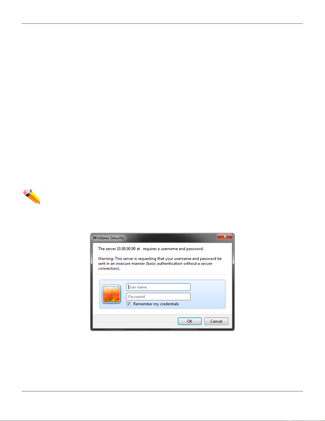
Login to the Web Manager
To begin managing the Switch, simply run the browser installed on your computer and point it to the IP address you
have defined for the device. The URL in the address bar should read something like: http://123.123.123.123, where the
numbers 123 represent the IP address of the Switch.
NOTE: The factory default IP address, for a normal port, is 10.90.90.90. The factory default IP address,
for the management port, is 192.168.0.1.
The Web User Interface’s authentication window can be accessed using the IP address of 10.90.90.90 (normal port),
as seen below.
Figure 1-1 Enter Network Password window
Leave both the User Name field and the Password field blank and click OK. This will open the Web-based user
interface. The Switch management features available in the web-based manager are explained below.
Web-based User Interface
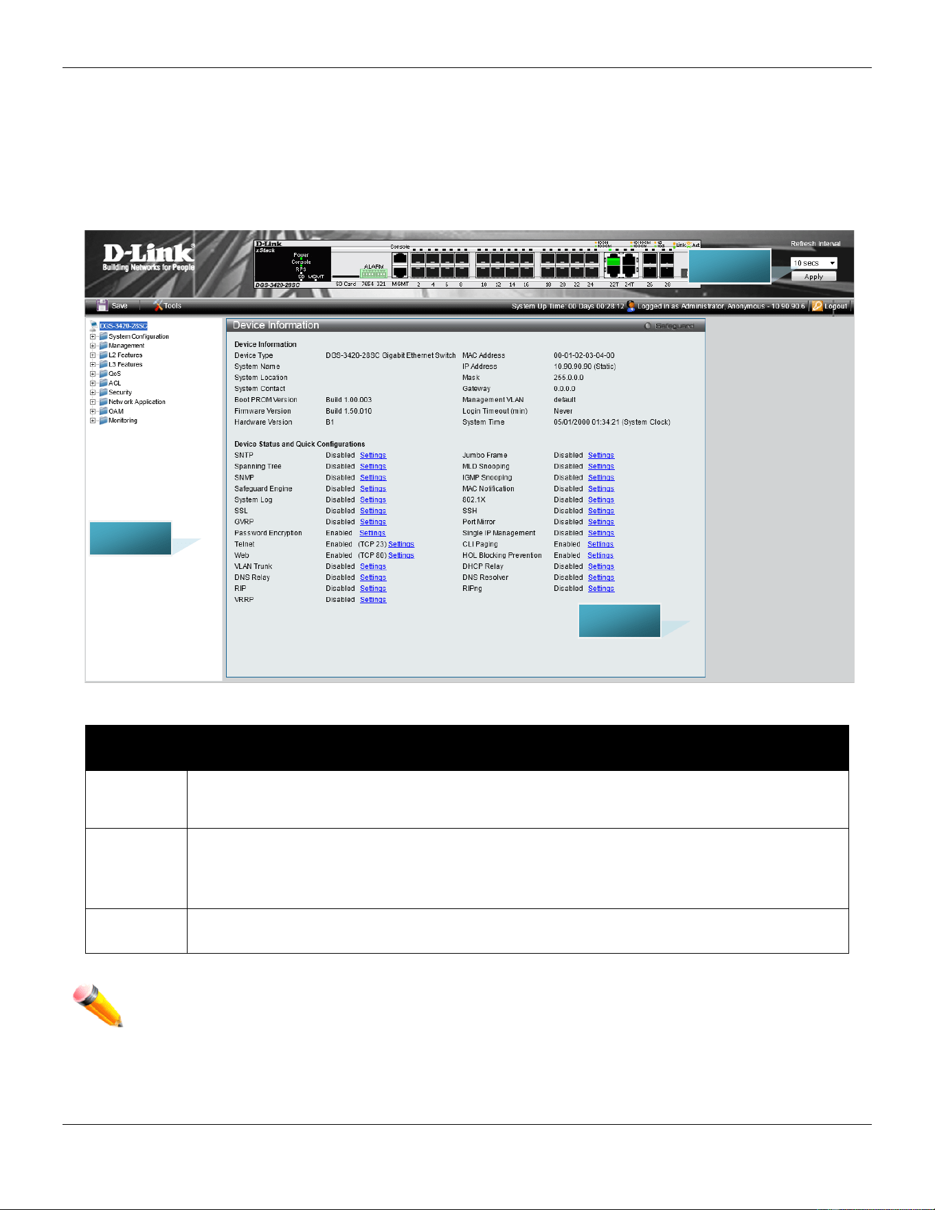
xStack® DGS-3420 Series Layer 2 Managed Stackable Gigabit Switch Web UI Reference Guide
6
The user interface provides access to various Switch configuration and management windows, allows you to view
performance statistics, and permits you to graphically monitor the system status.
Areas of the User Interface
The figure below shows the user interface. Three distinct areas divide the user interface, as described in the table.
Figure 1-2 Main Web-Manager page
Area
Number
Function
Area 1
Select the menu or window to display. Open folders and click the hyperlinked menu buttons
and subfolders contained within them to display menus. Click the D-Link logo to go to the D-
Link website.
Area 2
Presents a graphical near real-time image of the front panel of the Switch. This area displays
the Switch's ports, console and management port, showing port activity.
Some management functions, including save, reboot, download and upload are accessible
here.
Area 3
Presents switch information based on user selection and the entry of configuration data.
NOTE: Any changes made to the Switch configuration during the current session must be saved in the
Save Configuration / Log window or use the command line interface (CLI) command save.
Web Pages
AREA 2
AREA 1
AREA 3

xStack® DGS-3420 Series Layer 2 Managed Stackable Gigabit Switch Web UI Reference Guide
7
When connecting to the management mode of the Switch with a web browser, a login screen is displayed. Enter a user
name and password to access the Switch's management mode.
Below is a list of the main folders available in the Web interface:
System Configuration - In this section the user will be able to configure features regarding the Switch’s configuration.
Management - In this section the user will be able to configure features regarding the Switch’s management.
L2 Features - In this section the user will be able to configure features regarding the Layer 2 functionality of the Switch.
L3 Features - In this section the user will be able to configure features regarding the Layer 3 functionality of the Switch.
QoS - In this section the user will be able to configure features regarding the Quality of Service functionality of the
Switch.
ACL - In this section the user will be able to configure features regarding the Access Control List functionality of the
Switch.
Security - In this section the user will be able to configure features regarding the Switch’s security.
Network Application - In this section the user will be able to configure features regarding network applications
handled by the Switch.
OAM - In this section the user will be able to configure features regarding the Switch’s operations, administration and
maintenance (OAM).
Monitoring - In this section the user will be able to monitor the Switch’s configuration and statistics.
NOTE: Be sure to configure the user name and password in the User Accounts menu before
connecting the Switch to the greater network.

xStack® DGS-3420 Series Layer 2 Managed Stackable Gigabit Switch Web UI Reference Guide
8
Chapter 2 System Configuration
Device Information
System Information Settings
Port Configuration
PoE
Serial Port Settings
Warning Temperature Settings
System Log configuration
Time Range Settings
Port Group Settings
Time Settings
User Accounts Settings
Command Logging Settings
Stacking
Device Information
This window contains the main settings for all the major functions for the Switch. It appears automatically when you log
on to the Switch. To return to the Device Information window after viewing other windows, click the DGS-3420-28SC
link.
The Device Information window shows the Switch’s MAC Address (assigned by the factory and unchangeable), the
Boot PROM Version, Firmware Version, Hardware Version, and many other important types of information. This is
helpful to keep track of PROM and firmware updates and to obtain the Switch’s MAC address for entry into another
network device’s address table, if necessary. In addition, this window displays the status of functions on the Switch to
quickly assess their current global status.
Many functions are hyper-linked for easy access to enable quick configuration from this window.
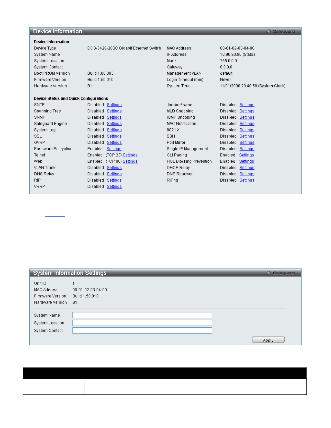
xStack® DGS-3420 Series Layer 2 Managed Stackable Gigabit Switch Web UI Reference Guide
9
Figure 2-1 Device Information window
Click the Settings link to navigate to the appropriate feature page for configuration.
System Information Settings
The user can enter a System Name, System Location, and System Contact to aid in defining the Switch.
To view the following window, click System Configuration > System Information Settings, as show below:
Figure 2-2 System Information Settings window
The fields that can be configured are described below:
Parameter Description
System Name
Enter a system name for the Switch, if so desired. This name will identify it in the Switch
network.
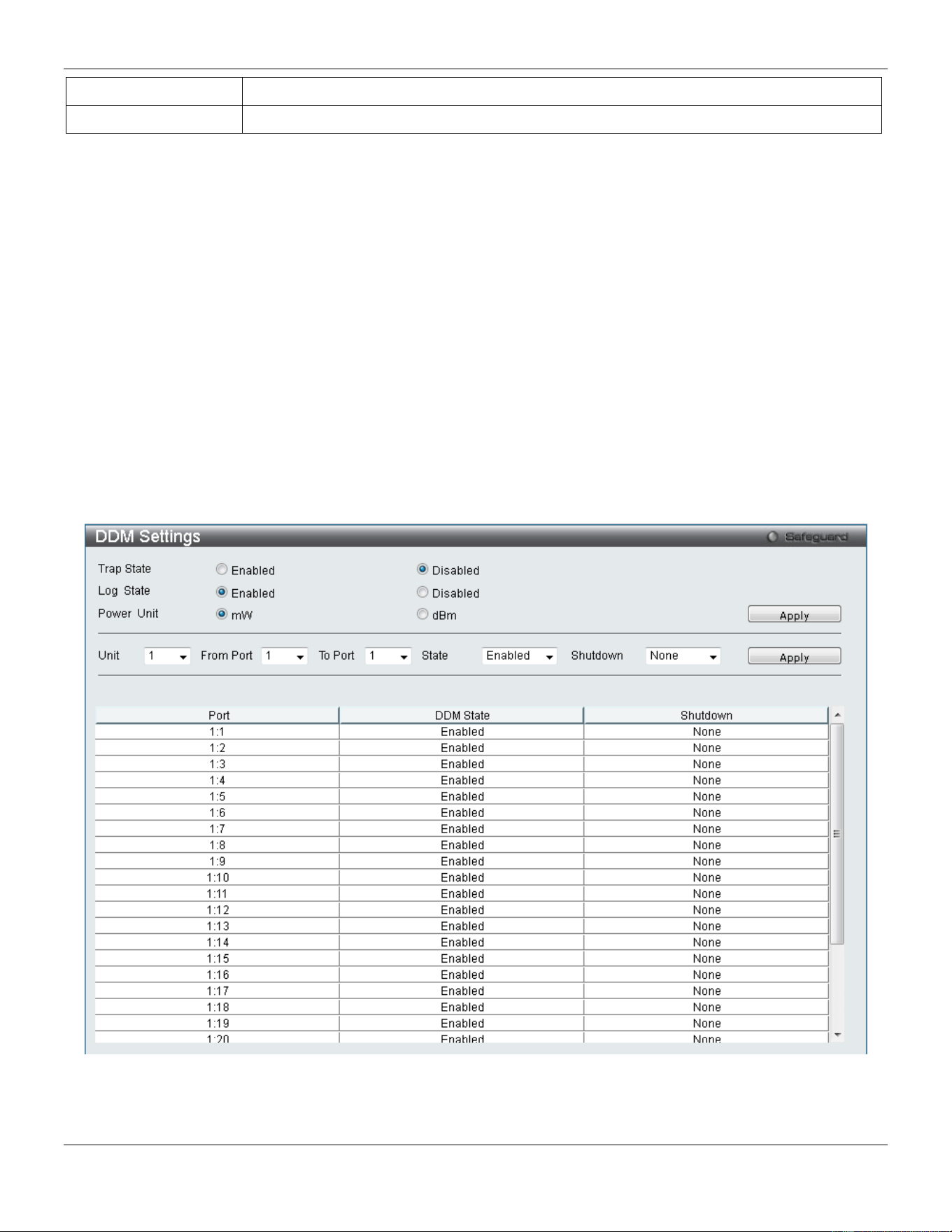
xStack® DGS-3420 Series Layer 2 Managed Stackable Gigabit Switch Web UI Reference Guide
10
System Location
Enter the location of the Switch, if so desired.
System Contact
Enter a contact name for the Switch, if so desired.
Click the Apply button to implement changes made.
Port Configuration
DDM
This folder contains windows that perform Digital Diagnostic Monitoring (DDM) functions on the Switch. There are
windows that allow the user to view the digital diagnostic monitoring status of SFP modules inserting to the Switch and
to configure alarm settings, warning settings, temperature threshold settings, voltage threshold settings, bias current
threshold settings, TX power threshold settings, and Rx power threshold settings.
DDM Settings
The window is used to configure the action that will occur for specific ports when an exceeding alarm threshold or
warning threshold event is encountered.
To view the following window, click System Configuration > Port Configuration > DDM > DDM Settings, as show
below:
Figure 2-3 DDM Settings window
The fields that can be configured are described below:
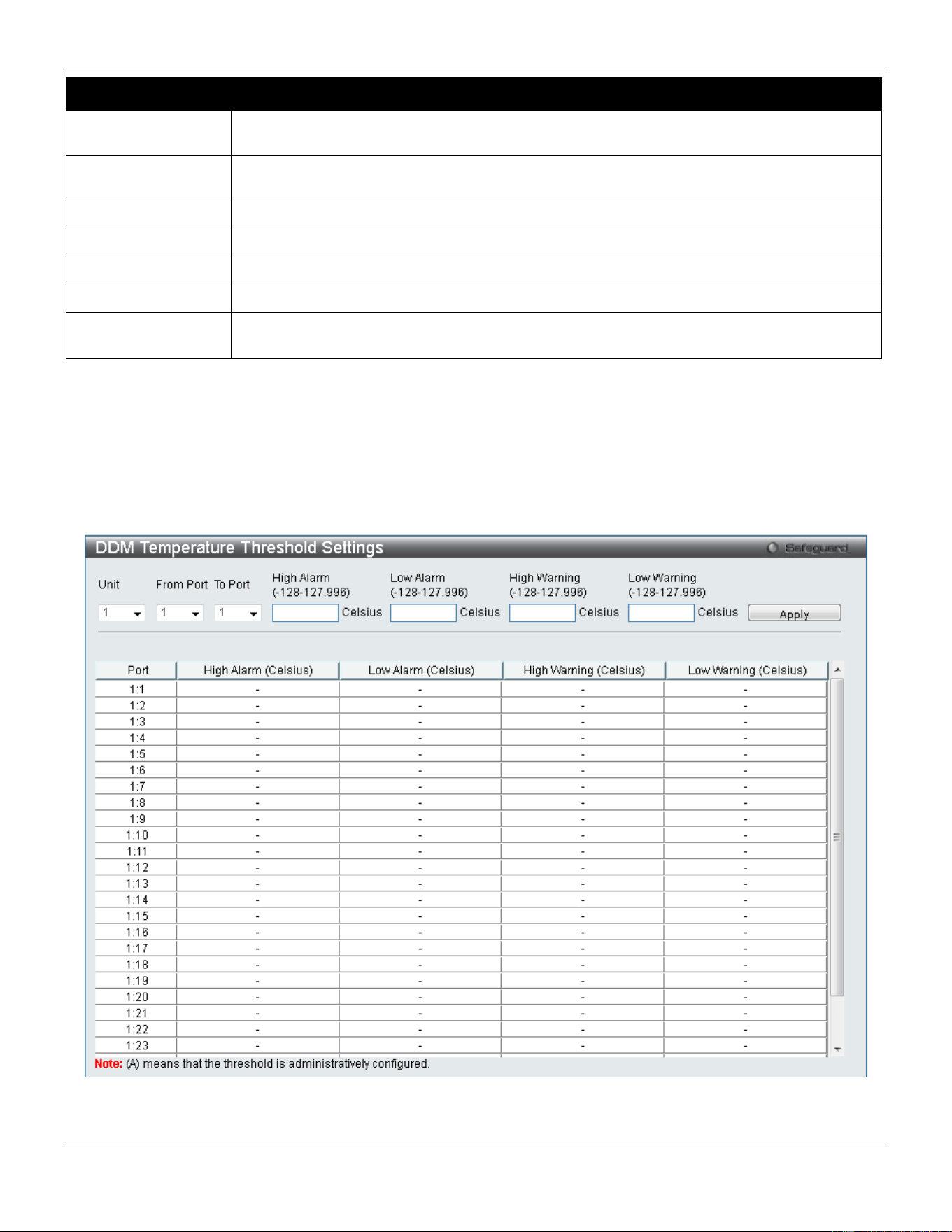
xStack® DGS-3420 Series Layer 2 Managed Stackable Gigabit Switch Web UI Reference Guide
11
Parameter Description
Trap State
Specify whether to send the trap, when the operating parameter exceeds the alarm or
warning threshold.
Log State
Specify whether to send the log, when the operating parameter exceeds the alarm or
warning threshold.
Power Unit
Select the power unit used here. Options to choose from are mW and dBm.
Unit
Select the unit to be configured.
From Port / To Port
Select a range of ports to be configured.
State
Use the drop-down menu to enable or disable the DDM state
Shutdown Specifies whether to shutdown the port, when the operating parameter exceeds the Alarm
or Warning threshold.
Click the Apply button to accept the changes made for each individual section.
DDM Temperature Threshold Settings
This window is used to configure the DDM Temperature Threshold Settings for specific ports on the Switch.
To view the following window, click System Configuration > Port Configuration > DDM > DDM Temperature
Threshold Settings, as show below:
Figure 2-4 DDM Temperature Threshold Settings window
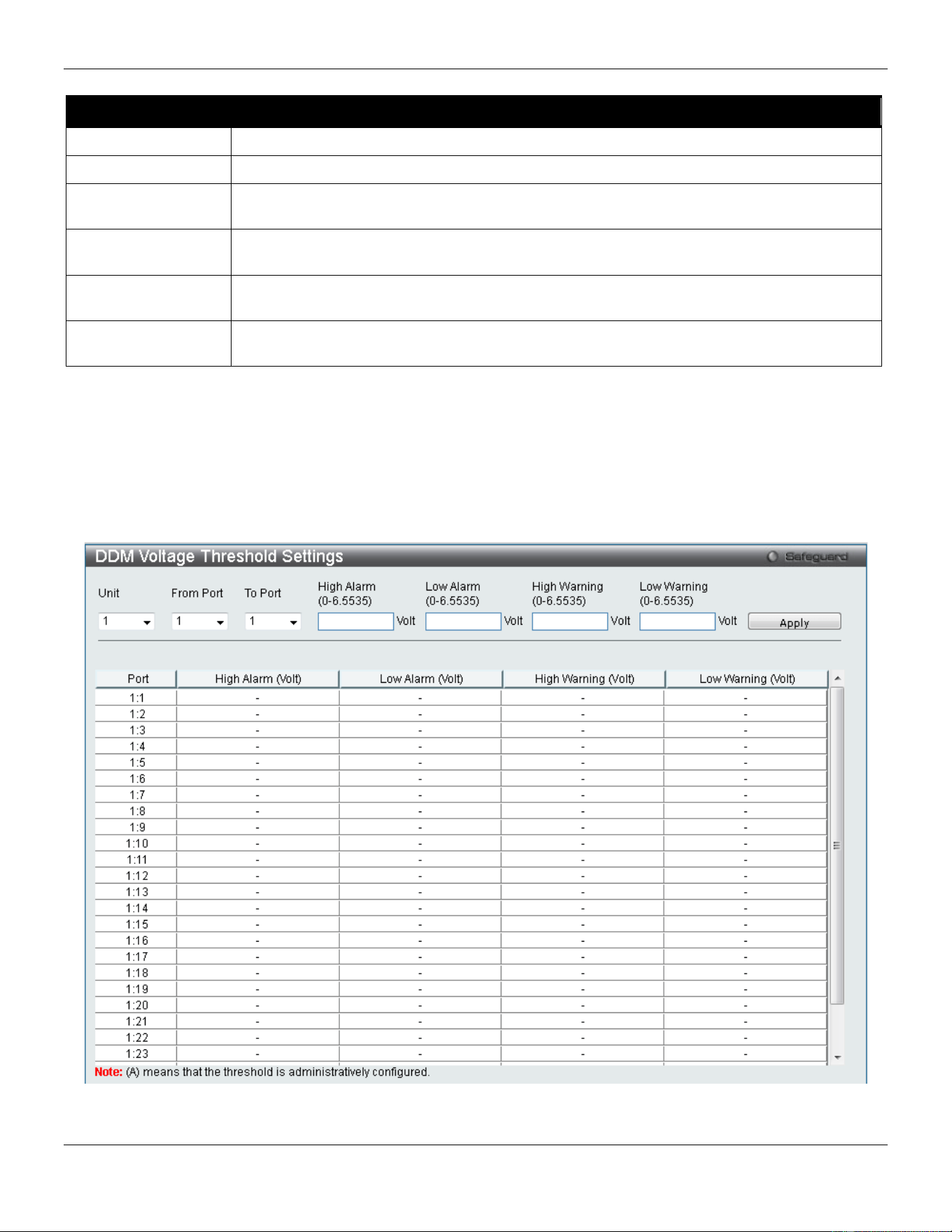
xStack® DGS-3420 Series Layer 2 Managed Stackable Gigabit Switch Web UI Reference Guide
12
The fields that can be configured are described below:
Parameter Description
Unit
Select the unit to be configured.
From Port / To Port
Select a range of ports to be configured.
High Alarm (-128-
127.996)
This is the highest threshold for the alarm. When the operating parameter rises above this
value, action associated with the alarm will be taken.
Low Alarm (-128-
127.996)
This is the lowest threshold for the alarm. When the operating parameter falls below this
value, action associated with the alarm will be taken.
High Warning (-128-
127.996)
This is the highest threshold for the warning. When the operating parameter rises above
this value, action associated with the warning will be taken.
Low Warning (-128-
127.996)
This is the lowest threshold for the warning. When the operating parameter falls below this
value, action associated with the warning will be taken.
Click the Apply button to accept the changes made.
DDM Voltage Threshold Settings
This window is used to configure the DDM Voltage Threshold Settings for specific ports on the Switch.
To view the following window, click System Configuration > Port Configuration > DDM > DDM Voltage Threshold
Settings, as show below:
Figure 2-5 DDM Voltage Threshold Settings window
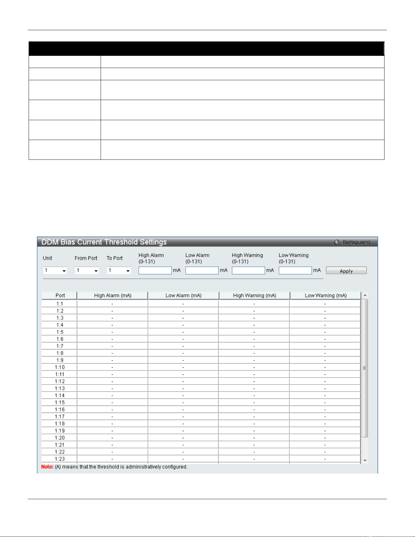
xStack® DGS-3420 Series Layer 2 Managed Stackable Gigabit Switch Web UI Reference Guide
13
The fields that can be configured are described below:
Parameter Description
Unit
Select the unit to be configured.
From Port / To Port
Select a range of ports to be configured.
High Alarm (0-
6.5535)
This is the highest threshold for the alarm. When the operating parameter rises above this
value, action associated with the alarm will be taken.
Low Alarm (0-
6.5535)
This is the lowest threshold for the alarm. When the operating parameter falls below this
value, action associated with the alarm will be taken.
High Warning (0-
6.5535)
This is the highest threshold for the warning. When the operating parameter rises above
this value, action associated with the warning will be taken.
Low Warning (0-
6.5535)
This is the lowest threshold for the warning. When the operating parameter falls below this
value, action associated with the warning will be taken.
Click the Apply button to accept the changes made.
DDM Bias Current Threshold Settings
This window is used to configure the threshold of the bias current for specific ports on the Switch.
To view the following window, click System Configuration > Port Configuration > DDM > DDM Bias Current
Threshold Settings, as show below:
Figure 2-6 DDM Bias Current Threshold Settings window

xStack® DGS-3420 Series Layer 2 Managed Stackable Gigabit Switch Web UI Reference Guide
14
The fields that can be configured are described below:
Parameter Description
Unit
Select the unit to be configured.
From Port / To Port
Select a range of ports to be configured.
High Alarm (0-131)
This is the highest threshold for the alarm. When the operating parameter rises above
this value, action associated with the alarm will be taken.
Low Alarm (0-131)
This is the lowest threshold for the alarm. When the operating parameter falls below this
value, action associated with the alarm will be taken.
High Warning (0-131)
This is the highest threshold for the warning. When the operating parameter rises above
this value, action associated with the warning will be taken.
Low Warning (0-131)
This is the lowest threshold for the warning. When the operating parameter falls below
this value, action associated with the warning will be taken.
Click the Apply button to accept the changes made.
DDM TX Power Threshold Settings
This window is used to configure the threshold of TX power for specific ports on the Switch.
To view the following window, click System Configuration > Port Configuration > DDM > DDM TX Power
Threshold Settings, as show below:
Figure 2-7 DDM TX Power Threshold Settings window
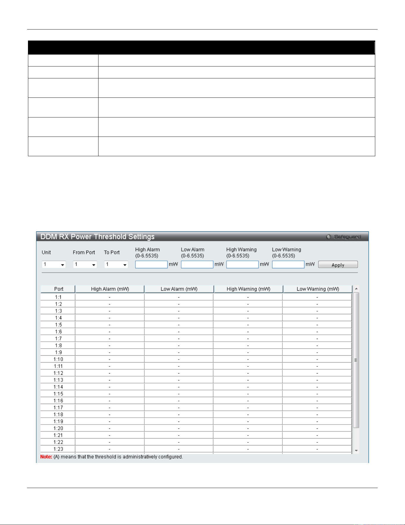
xStack® DGS-3420 Series Layer 2 Managed Stackable Gigabit Switch Web UI Reference Guide
15
The fields that can be configured are described below:
Parameter Description
Unit
Select the unit to be configured.
From Port / To Port
Select a range of ports to be configured.
High Alarm (0-
6.5535)
This is the highest threshold for the alarm. When the operating parameter rises above this
value, action associated with the alarm will be taken.
Low Alarm (0-
6.5535)
This is the lowest threshold for the alarm. When the operating parameter falls below this
value, action associated with the alarm will be taken.
High Warning (0-
6.5535)
This is the highest threshold for the warning. When the operating parameter rises above
this value, action associated with the warning will be taken.
Low Warning (0-
6.5535)
This is the lowest threshold for the warning. When the operating parameter falls below this
value, action associated with the warning will be taken.
Click the Apply button to accept the changes made.
DDM RX Power Threshold Settings
This window is used to configure the threshold of RX power for specific ports on the Switch.
To view the following window, click System Configuration > Port Configuration > DDM > DDM RX Power
Threshold Settings, as show below:
Figure 2-8 DDM RX Power Threshold Settings window
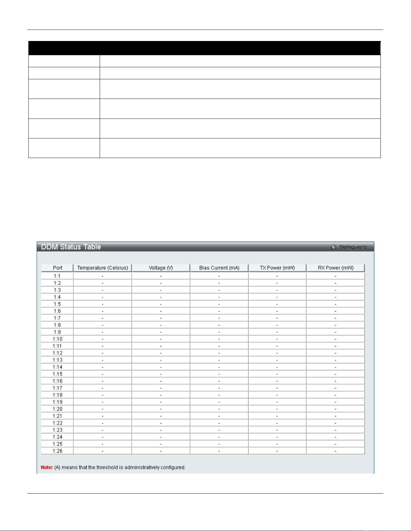
xStack® DGS-3420 Series Layer 2 Managed Stackable Gigabit Switch Web UI Reference Guide
16
The fields that can be configured are described below:
Parameter Description
Unit
Select the unit to be configured.
From Port / To Port
Select a range of ports to be configured.
High Alarm (0-
6.5535)
This is the highest threshold for the alarm. When the operating parameter rises above this
value, action associated with the alarm will be taken.
Low Alarm (0-
6.5535)
This is the lowest threshold for the alarm. When the operating parameter falls below this
value, action associated with the alarm will be taken.
High Warning (0-
6.5535)
This is the highest threshold for the warning. When the operating parameter rises above
this value, action associated with the warning will be taken.
Low Warning (0-
6.5535)
This is the lowest threshold for the warning. When the operating parameter falls below this
value, action associated with the warning will be taken.
Click the Apply button to accept the changes made.
DDM Status Table
This window is used to display the current operating digital diagnostic monitoring parameters and their values on the
SFP module for specified ports.
To view the following window, click System Configuration > Port Configuration > DDM > DDM Status Table, as
show below:
Figure 2-9 DDM Status Table window
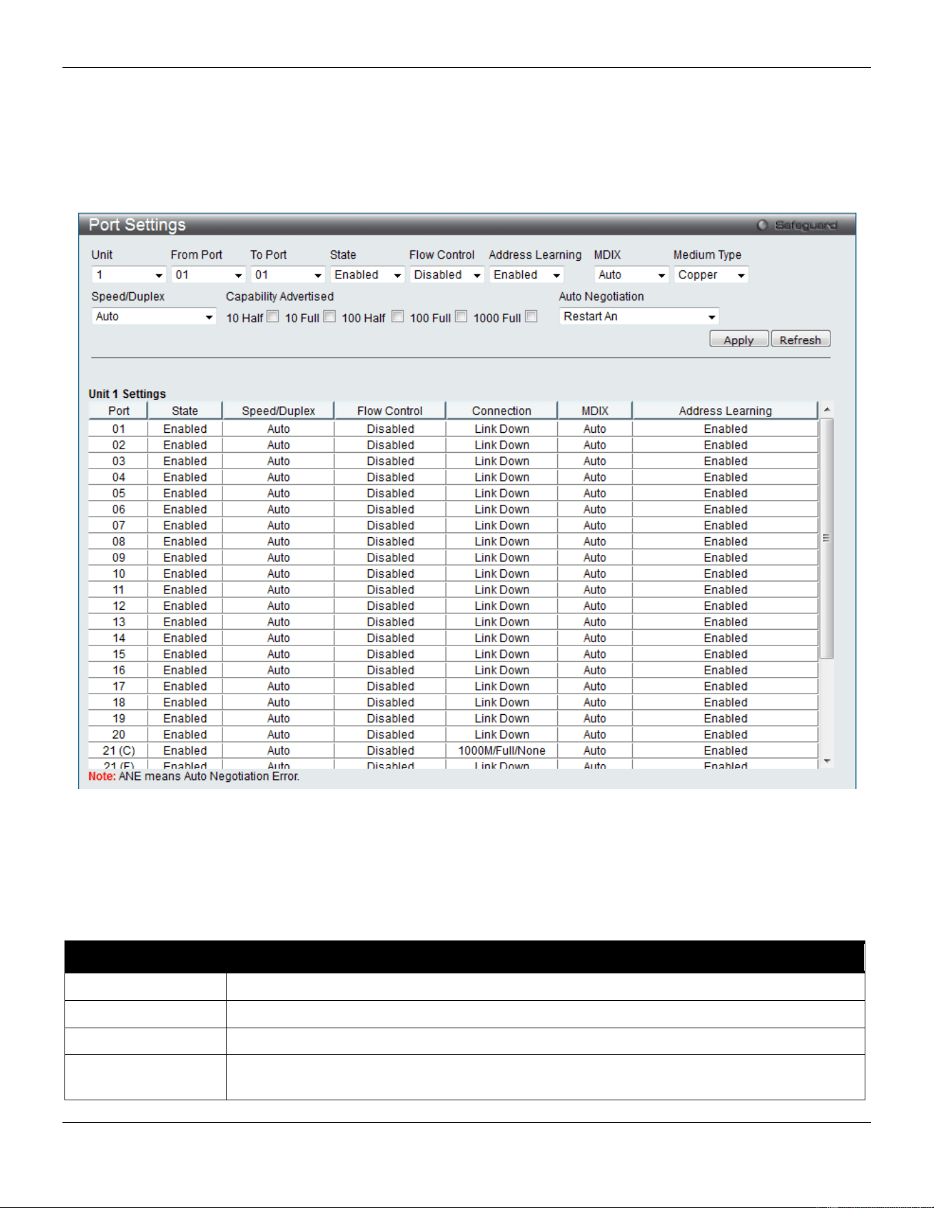
xStack® DGS-3420 Series Layer 2 Managed Stackable Gigabit Switch Web UI Reference Guide
17
Port Settings
This page used to configure the details of the switch ports.
To view the following window, click System Configuration > Port Configuration > Port Settings, as show below:
Figure 2-10 Port Settings window
To configure switch ports:
1. Choose the port or sequential range of ports using the From Port and To Port drop-down menus.
2. Use the remaining drop-down menus to configure the parameters described below:
The fields that can be configured are described below:
Parameter Description
Unit
Select the unit you wish to configure.
From Port / To Port
Select the appropriate port range used for the configuration here.
State
Toggle the State field to either enable or disable a given port or group of ports.
Speed/Duplex Use the drop-down menu to select the speed in Auto, 10M Half, 10M Full, 100M Half, 100M
Full, 1000M Full_Master and 1000M Full_Slave. Auto denotes auto-negotiation among 10,

xStack® DGS-3420 Series Layer 2 Managed Stackable Gigabit Switch Web UI Reference Guide
18
100 and 1000 Mbps devices, in full- or half-duplex (except 1000 Mbps which is always full
duplex). The Auto setting allows the port to automatically determine the fastest settings the
device the port is connected to can handle, and then to use those settings. The other
options are 10M Half, 10M Full, 100M Half, 100M Full, 1000M Full_Master, 1000M
Full_Slave, and 1000M Full. There is no automatic adjustment of port settings with any
option other than Auto.
The Switch allows the user to configure two types of gigabit connections; 1000M
Full_Master, and 1000M Full_Slave which refer to connections running a 1000BASE-T
cable for connection between the Switch port and other device capable of a gigabit
connection. The master setting (1000M Full_Master) will allow the port to advertise
capabilities related to duplex, speed and physical layer type. The master setting will also
determine the master and slave relationship between the two connected physical layers.
This relationship is necessary for establishing the timing control between the two physical
layers. The timing control is set on a master physical layer by a local source. The slave
setting (1000M Full_Slave) uses loop timing, where the timing comes from a data stream
received from the master. If one connection is set for 1000M Full_Master, the other side of
the connection must be set for 1000M Full_Slave. Any other configuration will result in a link
down status for both ports.
Capability
Advertised
When the Speed/Duplex is set to Auto, these capabilities are advertised during auto
negotiation.
Flow Control
Displays the flow control scheme used for the various port configurations. Ports configured
for full-duplex use 802.3x flow control, half-duplex ports use backpressure flow control, and
Auto ports use an automatic selection of the two. The default is Disabled.
Connection
Here the current connection speed will be displayed.
MDIX Auto - Select auto for auto sensing of the optimal type of cabling.
Normal - Select normal for normal cabling. If set to normal state, the port is in MDI mode
and can be connected to a PC NIC using a straight-through cable or a port (in MDI mode)
on another switch through a cross-over cable.
Cross - Select cross for cross cabling. If set to cross state, the port is in MDIX mode, and
can be connected to a port (in MDI mode) on another switch through a straight cable.
Address Learning Enable or disable MAC address learning for the selected ports. When Enabled, destination
and source MAC addresses are automatically listed in the forwarding table. When address
learning is Disabled, MAC addresses must be manually entered into the forwarding table.
This is sometimes done for reasons of security or efficiency. See the section on
Forwarding/Filtering for information on entering MAC addresses into the forwarding table.
The default setting is Enabled.
Medium Type
If configuring the Combo ports, this defines the type of transport medium to be used.
Auto Negotiation
Use the drop-down menu to specify the auto-negotiation configuration.
Restart An – Select to restart the auto-negotiation process
Remote Fault Advertisedt - The remote fault advertisement option will be configured.
Click the Apply button to implement changes made.
Click the Refresh button to refresh the display section of this page.
Port Description Settings
The Switch supports a port description feature where the user may name various ports.
To view the following window, click System Configuration > Port Configuration > Port Description Settings, as
show below:
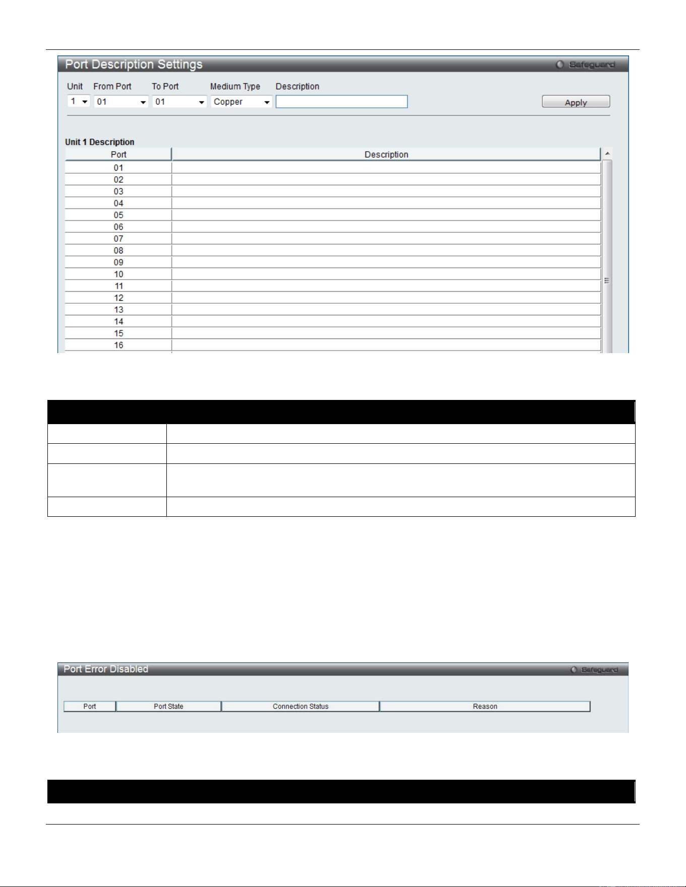
xStack® DGS-3420 Series Layer 2 Managed Stackable Gigabit Switch Web UI Reference Guide
19
Figure 2-11 Port Description Settings window
The fields that can be configured are described below:
Parameter Description
Unit
Select the unit you wish to configure.
From Port / To Port
Select the appropriate port range used for the configuration here.
Medium Type
Specify the medium type for the selected ports. If configuring the Combo ports, the Medium
Type defines the type of transport medium to be used, whether Copper or Fiber.
Description
Users may then enter a description for the chosen port(s).
Click the Apply button to implement changes made.
Port Error Disabled
The following window displays the information about ports that have been disconnected by the Switch when a packet
storm occurs or a loop was detected.
To view the following window, click System Configuration > Port Configuration > Port Error Disabled, as show
below:
Figure 2-12 Port Error Disabled
The fields that can be displayed are described below:
Parameter Description
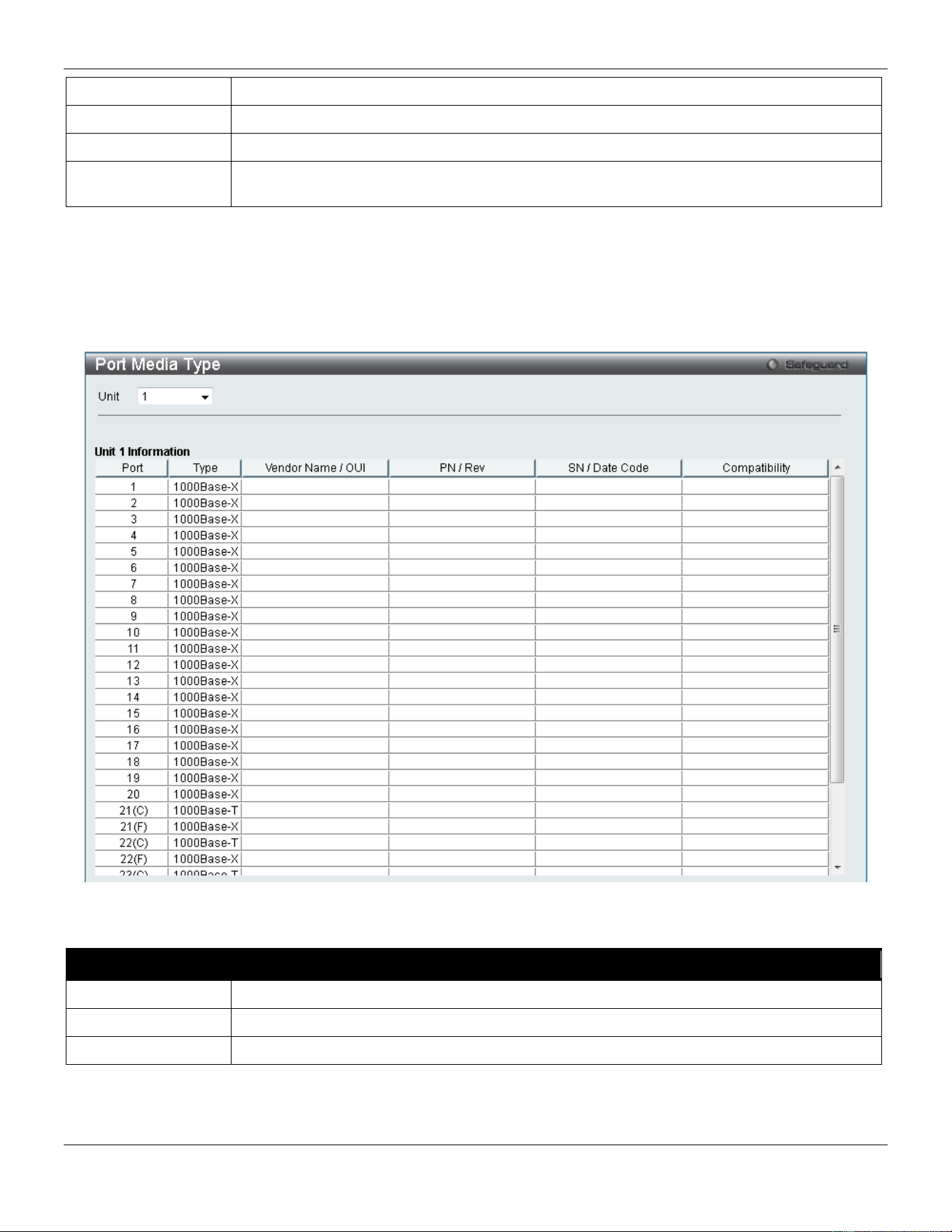
xStack® DGS-3420 Series Layer 2 Managed Stackable Gigabit Switch Web UI Reference Guide
20
Port
Display the port that has been error disabled.
Port State
Describe the current running state of the port, whether enabled or disabled.
Connection Status
Display the uplink status of the individual ports, whether enabled or disabled.
Reason
Describe the reason why the port has been error-disabled, such as it has become a
shutdown port for storm control.
Port Media Type
The following window displays the information about the port media type.
To view the following window, click System Configuration > Port Configuration > Port Media Type, as show below:
Figure 2-13 Port Media Type window
The fields that can be displayed are described below:
Parameter Description
Unit
Select the unit you wish to configure.
Port
Display the port number.
Type
Displays the port media type.
Port Auto Negotiation Information
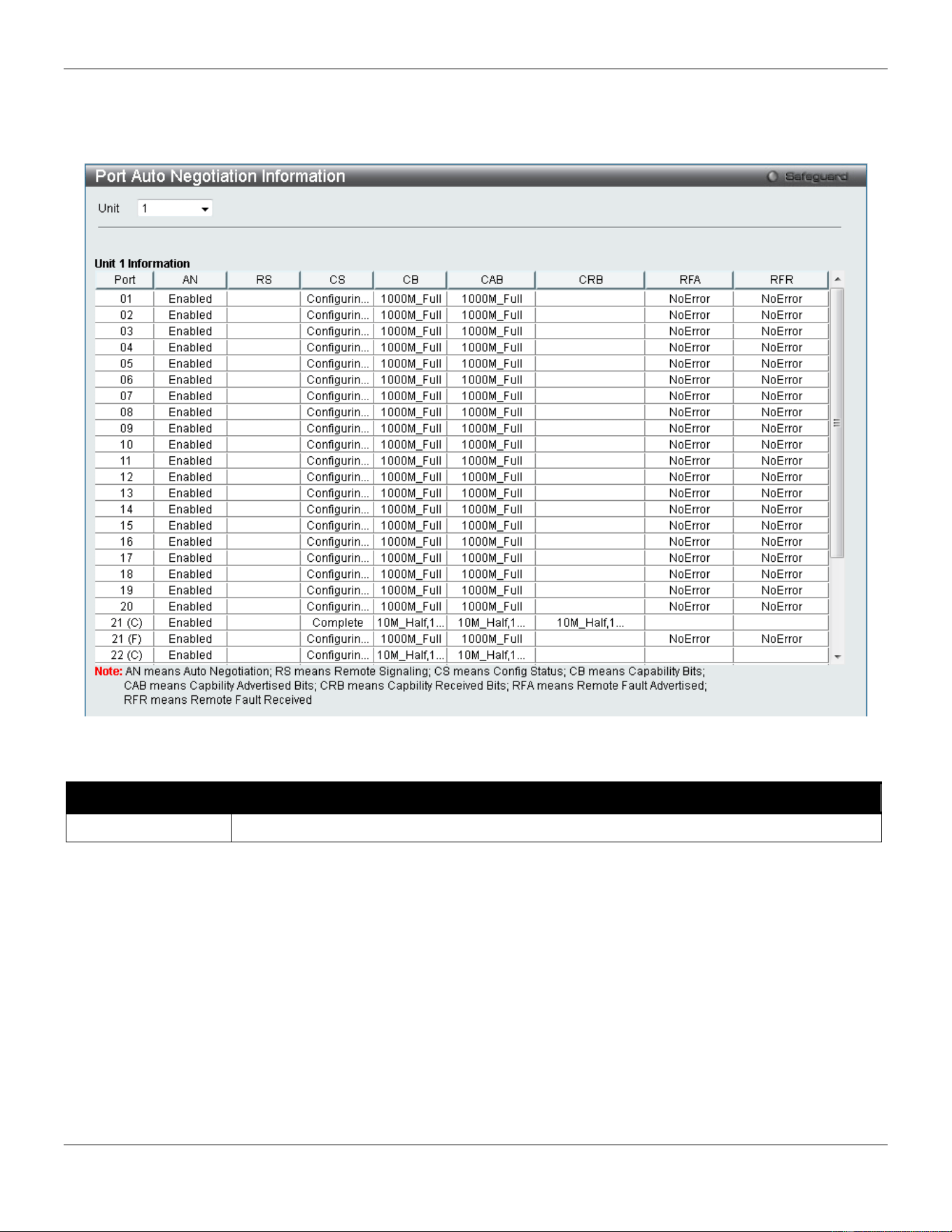
xStack® DGS-3420 Series Layer 2 Managed Stackable Gigabit Switch Web UI Reference Guide
21
The following window displays the detailed auto negotiation information.
To view the following window, click System Configuration > Port Configuration > Port Auto Negotiation
Information, as show below:
Figure 2-14 Port Auto Negotiation Information window
The fields that can be displayed are described below:
Parameter Description
Unit
Select the unit you wish to configure.
Jumbo Frame Settings
The Switch supports jumbo frames. Jumbo frames are Ethernet frames with more than 1,518 bytes of payload. The
Switch supports jumbo frames with a maximum frame size of up to 13,312 bytes.
To view the following window, click System Configuration > Port Configuration > Jumbo Frame Settings, as show
below:
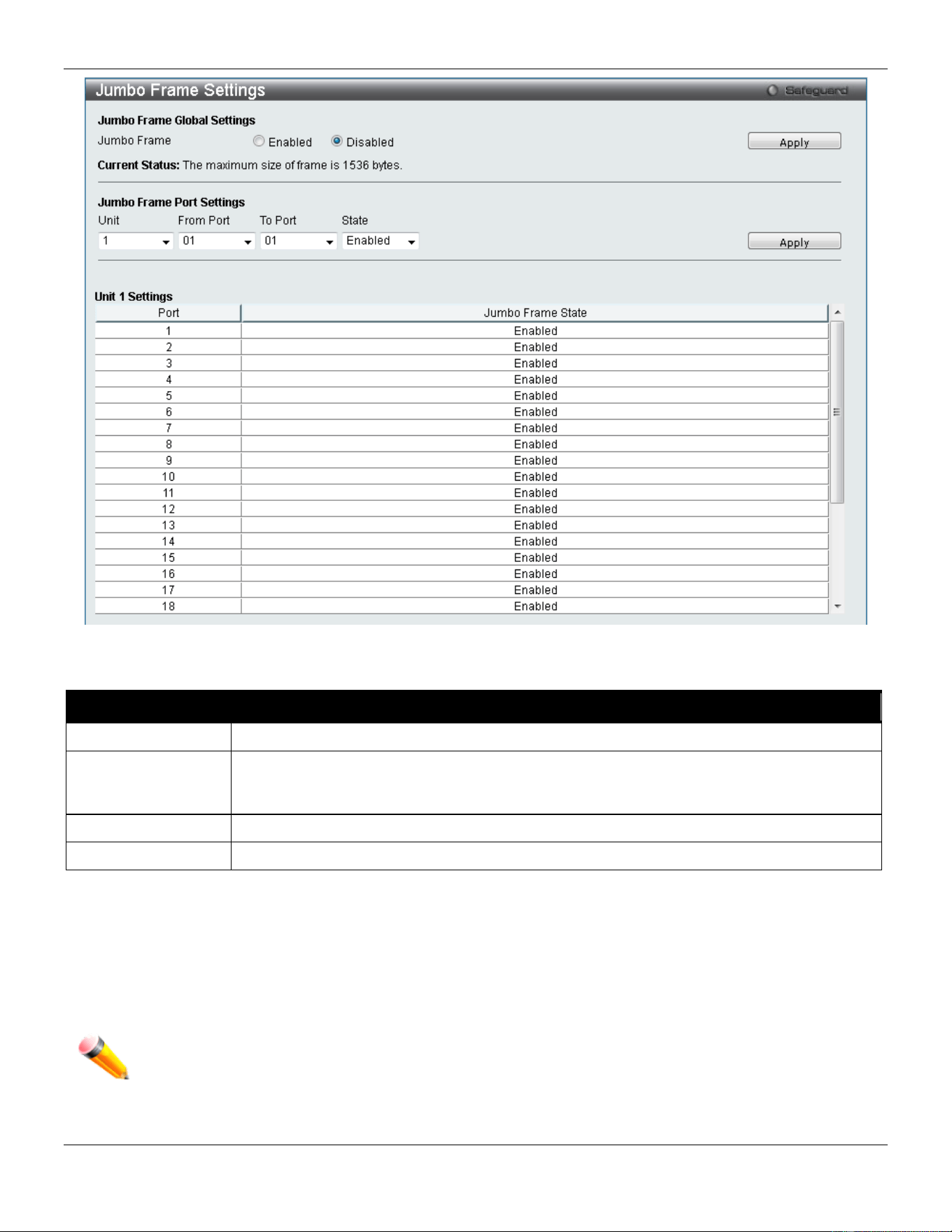
xStack® DGS-3420 Series Layer 2 Managed Stackable Gigabit Switch Web UI Reference Guide
22
Figure 2-15 Jumbo Frame Settings window
The fields that can be configured are described below:
Parameter Description
Unit
Select the unit you wish to configure.
Jumbo Frame
Use the radio buttons to enable or disable the Jumbo Frame function on the Switch. The
default is Disabled. When disabled, the maximum frame size is 1536 bytes. When enabled,
the maximum frame size is 13312 bytes.
From Port / To Port
Select the appropriate port range used for the configuration here.
State
Use the drop-down menu to enable the Jumbo Frame for the port.
Click the Apply button to implement changes made.
EEE Settings
Energy Efficient Ethernet (EEE) is defined in IEEE 802.3az. It is designed to reduce the energy consumption of a link
when no packets are being sent.
NOTE: This feature is only available on hardware version B1 and later.
To view the following window, click System Configuration > Port Configuration > EEE Settings, as show below:
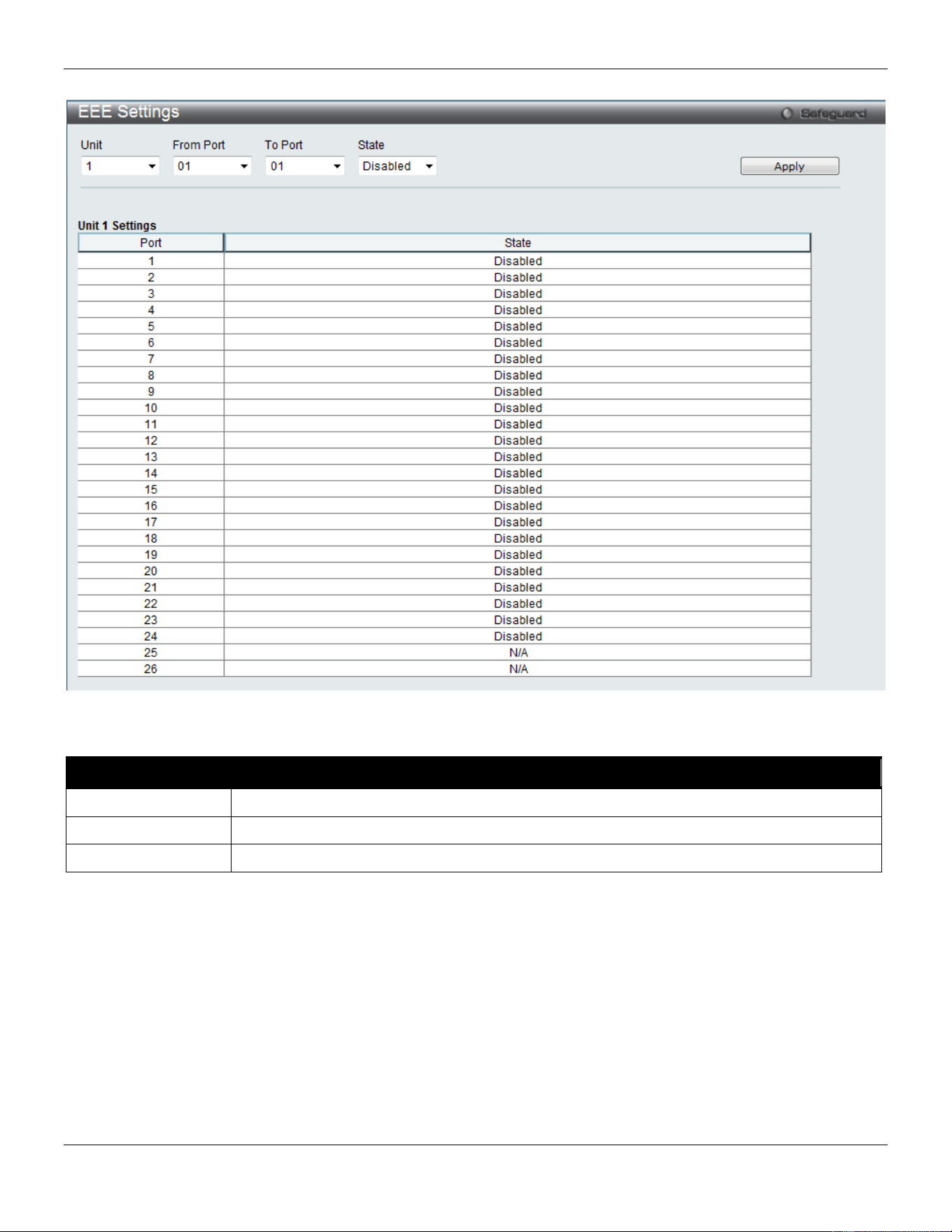
xStack® DGS-3420 Series Layer 2 Managed Stackable Gigabit Switch Web UI Reference Guide
23
Figure 2-16 EEE Settings window
The fields that can be configured are described below:
Parameter Description
Unit
Select the unit you wish to configure.
From Port / To Port
Select the appropriate port range used for the configuration here.
State
Select to enable or disable the state of this feature here.
Click the Apply button to implement changes made.
PoE
The DGS-3420-28PC and DGS-3420-52P switches support Power over Ethernet (PoE) as defined by the IEEE 802.3af
and 802.3at. All ports can support PoE up to 30W. All the ports can supply about 48 VDC power to Powered Devices
(PDs) over Category 5 or Category 3 UTP Ethernet cables. The Switch follows the standard PSE (Power Sourcing
Equipment) pinout Alternative A, whereby power is sent out over pins 1, 2, 3 and 6. The Switches work with all D-Link
802.3af capable devices.
The Switch includes the following PoE features:
• Auto-discovery recognizes the connection of a PD (Powered Device) and automatically sends power to it.
xStack® DGS-3420 Series Layer 2 Managed Stackable Gigabit Switch Web UI Reference Guide
24
• The Auto-disable feature occurs under two conditions: firstly, if the total power consumption exceeds the
system power limit; and secondly, if the per port power consumption exceeds the per port power limit.
• Active circuit protection automatically disables the port if there is a short. Other ports will remain active.
Based on 802.3af/at PDs receive power according to
the following classification:
PSE provides power according to the following
classification:
Class Maximum power available to PD Class Max. power used by PSE
0 12.95W 0 15.4W
1 3.84W 1 4W
2 6.49W 2 7W
3 12.95W 3 15.4W
4 29.5W User Define 35W
To configure the PoE features on the Switch, click System Configuration > PoE. The PoE System Settings window
is used to assign a power limit and power disconnect method for the whole PoE system. To configure the Power Limit
for the PoE system, enter a value between 37W and 760W for the Switch in the Power Limit field. When the total
consumed power exceeds the power limit, the PoE controller (located in the PSE) disconnects the power to prevent
overloading the power supply.
PoE System Settings
To view the following window, click System Configuration > PoE > PoE System Settings, as show below:
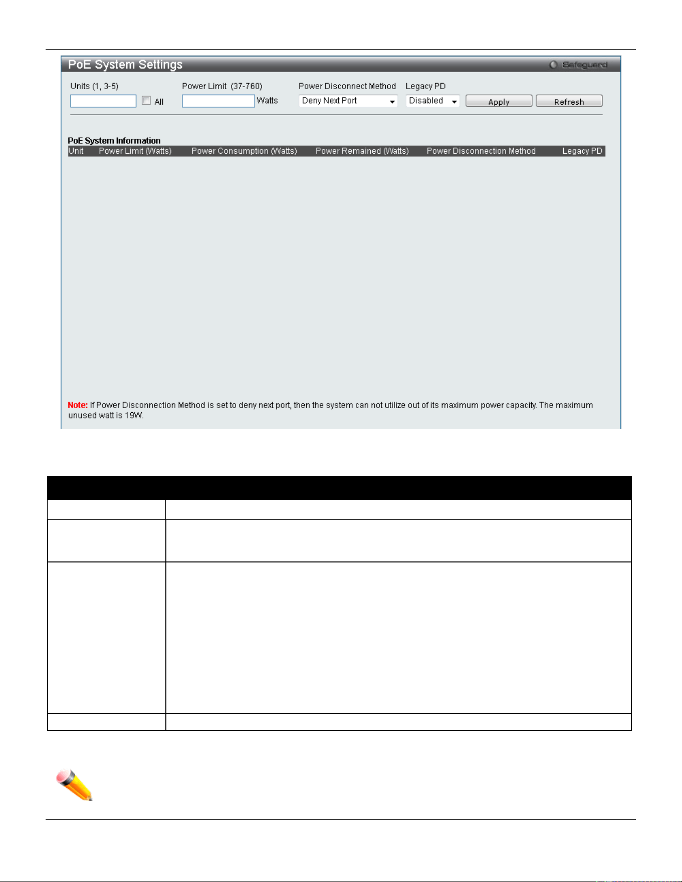
xStack® DGS-3420 Series Layer 2 Managed Stackable Gigabit Switch Web UI Reference Guide
25
Figure 2-17 PoE System Settings window
The following parameters can be configured:
Parameter Description
Unit
Select the unit you wish to configure. Tick the All check box to select all units.
Power Limit (37-
760)
Sets the limit of power to be used from the Switch’s power source to PoE ports. The user
may configure a Power Limit between 37W and 760W for the DGS-3420-28PC and DGS-
3420-52P.
Power Disconnect
Method
The PoE controller uses either Deny Next Port or Deny Low Priority Port to offset the power
limit being exceeded and keeps the Switch’s power at a usable level. Use the drop down
menu to select a Power Disconnect Method. The default Power Disconnect Method is
Deny Next Port. Both Power Disconnection Methods are described below:
Deny Next Port – After the power limit has been exceeded, the next port attempting to
power up is denied, regardless of its priority. If Power Disconnection Method is set to Deny
Next Port, the system cannot utilize out of its maximum power capacity. The maximum
unused watt is 19W.
Deny Low Priority Port – After the power limit has been exceeded, the next port attempting
to power up causes the port with the lowest priority to shut down so as to allow the high-
priority and critical priority ports to power up.
Legacy PD
Use the drop-down menu to enable or disable detecting legacy PDs signal.
Click Apply to implement changes made.
NOTE: The Power Limit for this Switch without a Redundant Power Supply (RPS) is 390W. When the
user adds an RPS, like the DPS-700, for the DGS-3420-28PC and the DGS-3420-52P, the Power
Limit must be set to 760W.
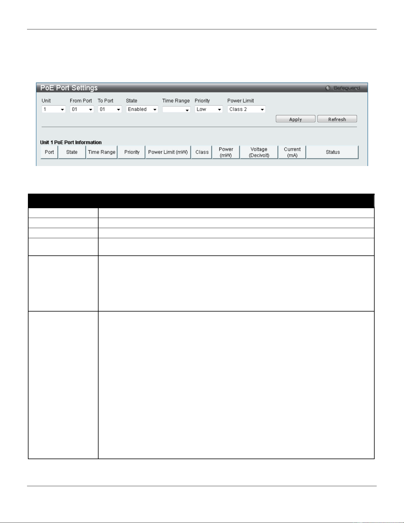
xStack® DGS-3420 Series Layer 2 Managed Stackable Gigabit Switch Web UI Reference Guide
26
PoE Port Settings
To view the following window, click System Configuration > PoE > PoE Port Settings, as show below:
Figure 2-18 PoE Port Settings window
The following parameters can be configured:
Parameter Description
Unit
Select the unit you wish to configure.
From Port / To Port
Select a range of ports from the drop-down menus to be enabled or disabled for PoE.
State
Use the drop-down menu to enable or disable ports for PoE.
Time Range
Select a range of the time to the port set as POE. If Time Range is configured, the power
can only be supplied during the specified period of time.
Priority
Use the drop-down menu to select the priority of the PoE ports. Port priority determines the
priority which the system attempts to supply the power to the ports. There are three levels of
priority that can be selected, Critical, High, and Low. When multiple ports happen to have
the same level of priority, the port ID will be used to determine the priority. The lower port ID
has higher priority. The setting of priority will affect the order of supplying power. Whether
the disconnect method is set to deny low priority port, the priority of each port will be used
by the system to manage the supply of power to ports.
Power Limit
This function is used to configure the per-port power limit. If a port exceeds its power limit, it
will shut down.
Based on 802.3af/802.3at, there are different PD classes and power consumption ranges;
Class 0 – 0.44~12.95W
Class 1 – 0.44~3.84W
Class 2 – 3.84~6.49W
Class 3 – 6.49~12.95W
Class 4 – 29.5W
The following is the power limit applied to the port for these five classes. For each class, the
power limit is a little more than the power consumption range for that class. This takes into
account any power loss on the cable. Thus, the following are the typical values;
Class 0 – 15400mW
Class 1 – 4000mW
Class 2 – 7000mW
Class 3 – 15400mW
User Define – 35000mW
Click Apply to implement changes made. The port status of all PoE configured ports is displayed in the table in the
bottom half of the screen shown above.
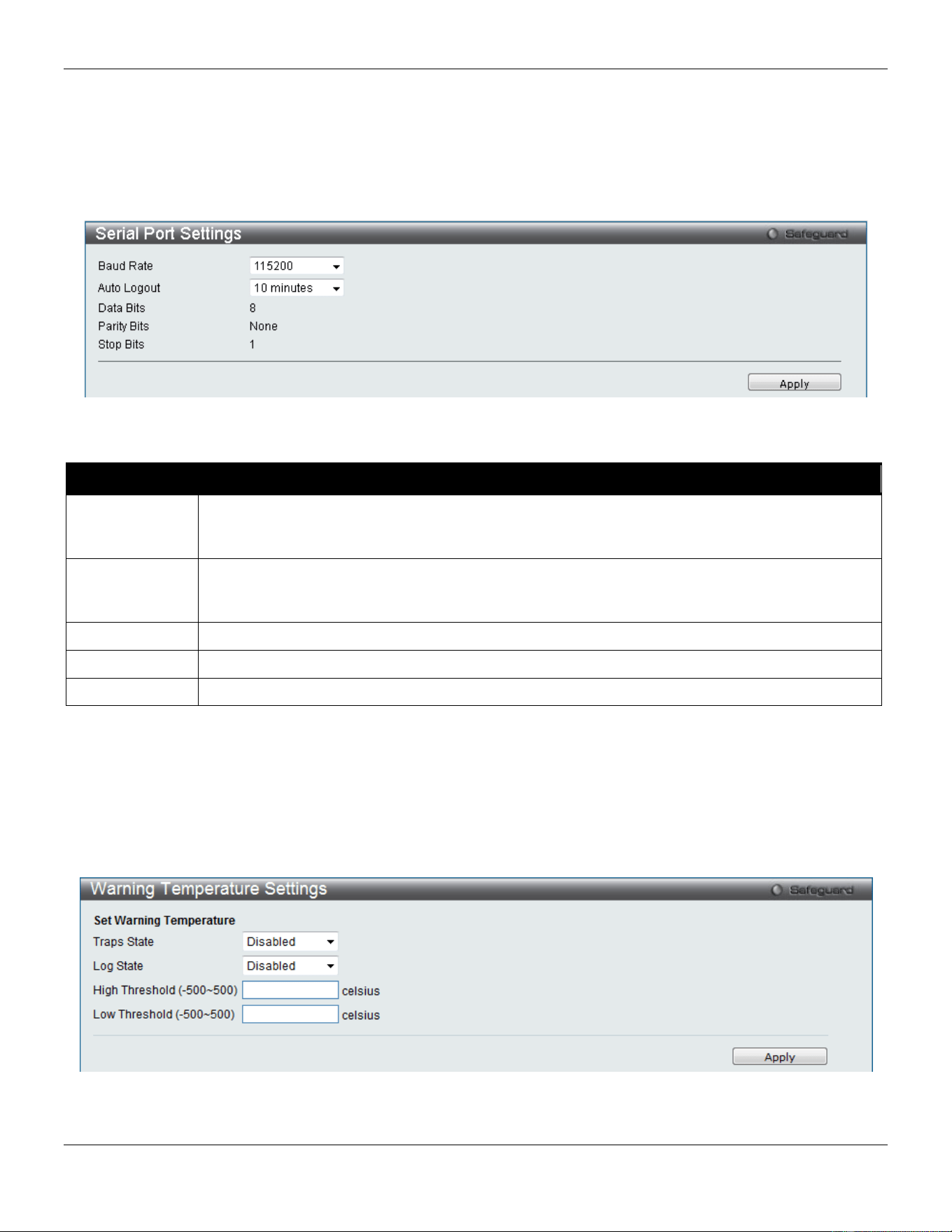
xStack® DGS-3420 Series Layer 2 Managed Stackable Gigabit Switch Web UI Reference Guide
27
Serial Port Settings
This window allows the user to adjust the Baud Rate and the Auto Logout values.
To view the following window, click System Configuration > Serial Port Settings, as show below:
Figure 2-19 Serial Port Settings window
The fields that can be configured are described below:
Parameter Description
Baud Rate
Specify the baud rate for the serial port on the Switch. There are four possible baud rates to
choose from, 9600, 19200, 38400 and 115200. For a connection to the Switch using the console
port, the baud rate must be set to 115200, which is the default setting.
Auto Logout
Select the logout time used for the console interface. This automatically logs the user out after
an idle period of time, as defined. Choose from the following options: 2, 5, 10, 15 minutes or
Never. The default setting is 10 minutes.
Data Bits
Display the data bits used for the serial port connection.
Parity Bits
Display the parity bits used for the serial port connection.
Stop Bits
Display the stop bits used for the serial port connection.
Click the Apply button to implement changes made.
Warning Temperature Settings
This window allows the user to configure the system warning temperature parameters.
To view the following window, click System Configuration > Warning Temperature Settings, as show below:
Figure 2-20 Warning Temperature Settings window
The fields that can be configured are described below:
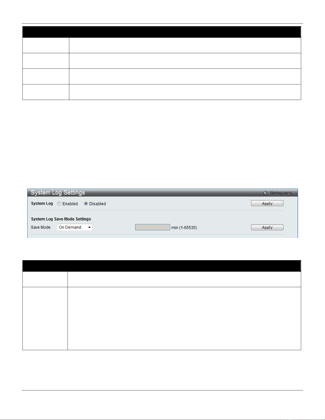
xStack® DGS-3420 Series Layer 2 Managed Stackable Gigabit Switch Web UI Reference Guide
28
Parameter Description
Traps State
Use the drop-down menu to enable or disable the traps state option of the warning temperature
setting.
Log State
Use the drop-down menu to enable or disable the log state option of the warning temperature
setting.
High Threshold
(-500-500)
Enter the high threshold value of the warning temperature setting.
Low Threshold
(-500-500)
Enter the low threshold value of the warning temperature setting.
Click the Apply button to implement changes made.
System Log configuration
System Log Settings
The Switch allows users to choose a method for which to save the switch log to the flash memory of the Switch.
To view the following window, click System Configuration > System Log Configuration > System Log Settings, as
show below:
Figure 2-21 System Log Settings window
The fields that can be configured are described below:
Parameter Description
System Log Use the radio buttons to enable or disable the system log settings. Click the Apply button to
accept the changes made.
Save Mode
Use the drop-down menu to choose the method for saving the switch log to the flash memory.
The user has three options:
On Demand – Users who choose this method will only save log files when they manually tell the
Switch to do so, either using the Save Log link in the Save folder.
Time Interval – Users who choose this method can configure a time interval by which the Switch
will save the log files, in the box adjacent to this configuration field. The user may set a time
between 1 and 65535 minutes.
Log Trigger – Users who choose this method will have log files saved to the Switch every time a
log event occurs on the Switch.
Click the Apply button to implement changes made.
System Log Server Settings
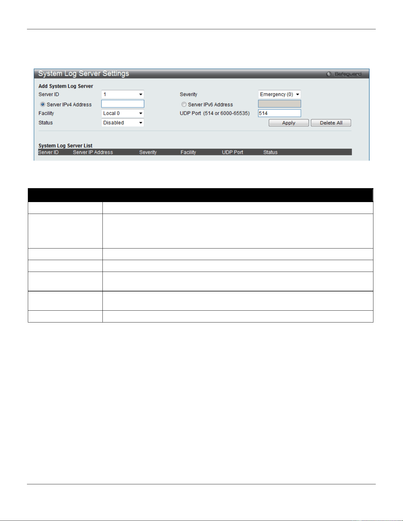
xStack® DGS-3420 Series Layer 2 Managed Stackable Gigabit Switch Web UI Reference Guide
29
The Switch can send System log messages to up to four designated servers using the System Log Server.
To view the following window, click System Configuration > System Log Configuration > System Log Server
Settings, as show below:
Figure 2-22 System Log Server Settings
The fields that can be configured are described below:
Parameter Description
Server ID
System log server settings index (1 to 4).
Severity
Use the drop-down menu to select the higher level of messages that will be sent. All
messages which level is higher than selecting level will be sent. The options are
Emergency(0), Alert(1), Critical(2), Error(3), Warning(4), Notice(5), Informational(6) and
Debug(7).
Server IPv4 Address
The IPv4 address of the System log server.
Server IPv6 Address
The IPv6 address of the System log server.
Facility Use the drop-down menu to select Local 0, Local 1, Local 2, Local 3, Local 4, Local 5,
Local 6, or Local 7.
UDP Port
(514 or 6000-65535)
Type the UDP port number used for sending System log messages. The default is 514.
Status
Choose Enabled or Disabled to activate or deactivate.
Click the Apply button to accept the changes made.
Click the Delete All button to remove all servers configured.
System Log
Users can view and delete the local history log as compiled by the Switch's management agent.
To view the following window, click System Configuration > System Log Configuration > System Log, as show
below:
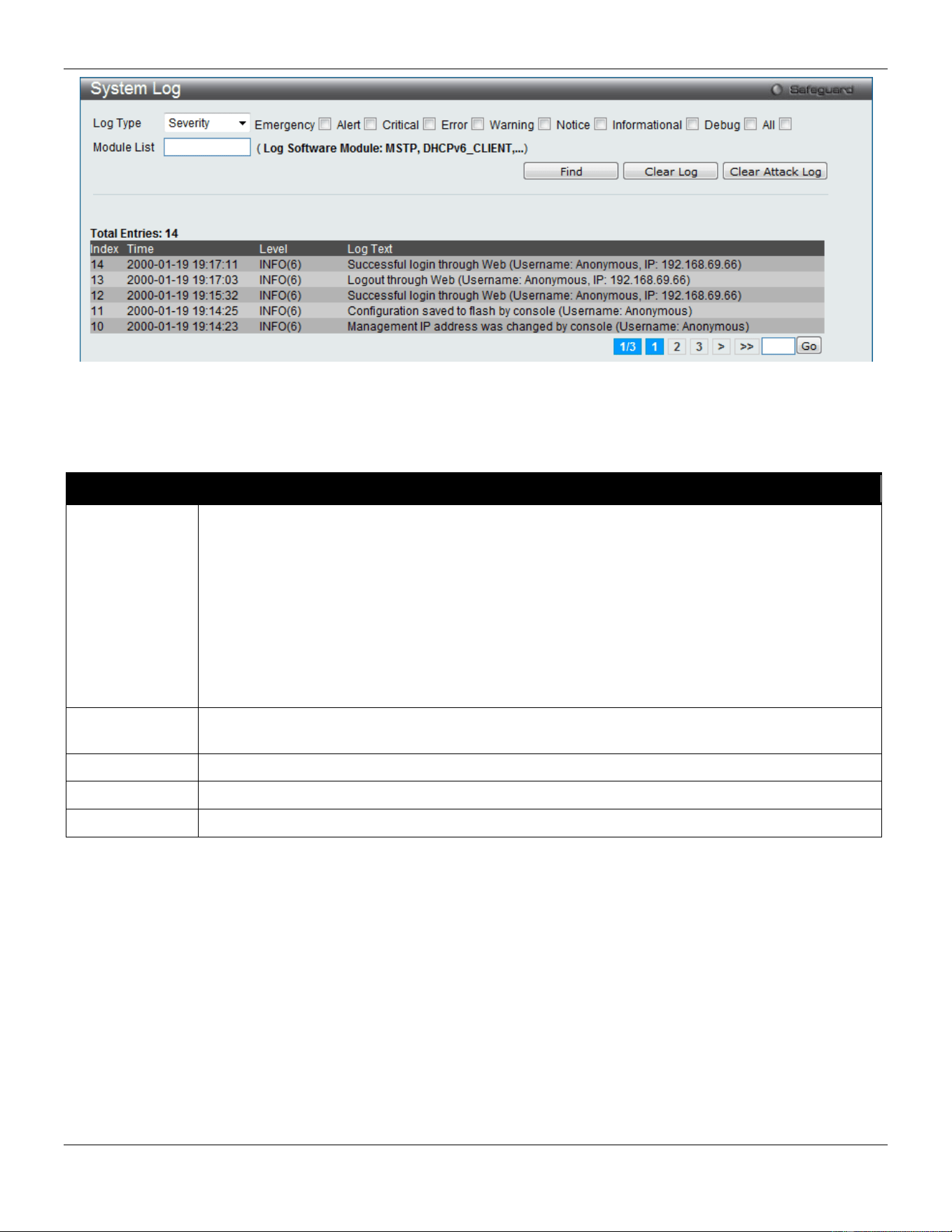
xStack® DGS-3420 Series Layer 2 Managed Stackable Gigabit Switch Web UI Reference Guide
30
Figure 2-23 System Log window
The Switch can record event information in its own log. Click Go to go to the next page of the System Log window.
The fields that can be configured or displayed are described below:
Parameter Description
Log Type
In the drop-down menu the user can select the log type that will be displayed.
Severity - When selecting Severity from the drop-down menu, a secondary tick must be made.
Secondary ticks are Emergency, Alert, Critical, Error, Warning, Notice, Informational and
Debug. To view all information in the log, simply tick the All check box. Enter the module name
to search for the specific module.
Module List - When selecting Module List, the module name must be manually entered.
Available modules are MSTP, DHCPv6_CLIENT, DHCPv6_RELAY, ERPS, ERROR_LOG,
CFM_EXT, and DHCPv6_SERVER.
Attack Log - When selecting Attack Log all attacks will be listed. Select a unit from the drop-
down menu to display the result of the unit.
Index
A counter incremented whenever an entry to the Switch's history log is made. The table displays
the last entry (highest sequence number) first.
Time
Display the time in days, hours, minutes, and seconds since the Switch was last restarted.
Level
Display the level of the log entry.
Log Text
Display text describing the event that triggered the history log entry.
Click the Find button to display the log in the display section according to the selection made.
Click the Clear Log button to clear the entries from the log in the display section.
Click the Clear Attack Log button to clear the entries from the attack log in the display section.
Enter a page number and click the Go button to navigate to a specific page when multiple pages exist.
System Log & Trap Settings
The Switch allows users to configure the system log source IP interface addresses here.
To view the following window, click System Configuration > System Log Configuration > System Log & Trap
Settings, as show below:
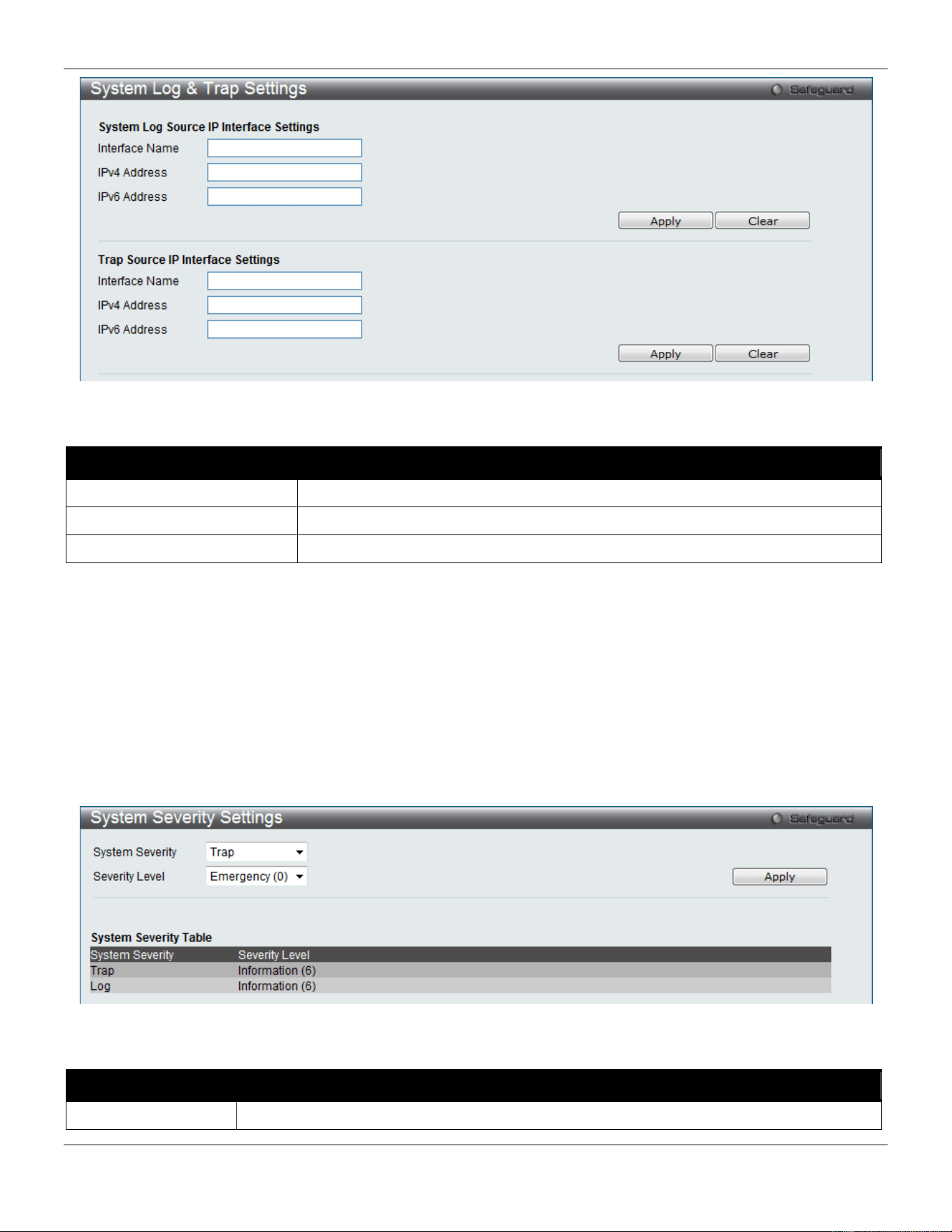
xStack® DGS-3420 Series Layer 2 Managed Stackable Gigabit Switch Web UI Reference Guide
31
Figure 2-24 System Log & Trap Settings window
The fields that can be configured are described below:
Parameter Description
Interface Name
Enter the IP interface name used.
IPv4 Address
Enter the IPv4 address used.
IPv6 Address
Enter the IPv6 address used.
Click the Apply button to accept the changes made.
Click the Clear button to clear all the information entered in the fields.
System Severity Settings
The Switch can be configured to allow alerts be logged or sent as a trap to an SNMP agent. The level at which the alert
triggers either a log entry or a trap message can be set as well. Use the System Severity Settings window to set the
criteria for alerts. The current settings are displayed below the System Severity Table.
To view the following window, click System Configuration > System Log Configuration > System Severity
Settings, as show below:
Figure 2-25 System Severity Settings window
The fields that can be configured are described below:
Parameter Description
System Severity
Choose how the alerts are used from the drop-down menu. Select Log to send the alert of
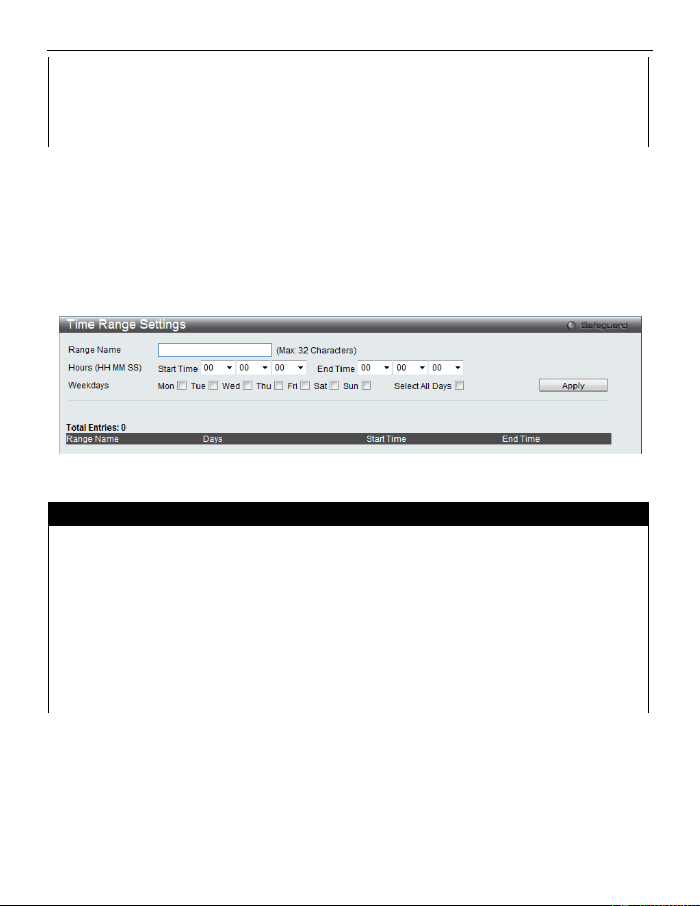
xStack® DGS-3420 Series Layer 2 Managed Stackable Gigabit Switch Web UI Reference Guide
32
the Severity Type configured to the Switch’s log for analysis. Choose Trap to send it to an
SNMP agent for analysis, or select All to send the chosen alert type to an SNMP agent and
the Switch’s log for analysis.
Severity Level
This drop-down menu allows you to select the level of messages that will be sent. The
options are Emergency (0), Alert (1), Critical (2), Error (3), Warning (4), Notice (5),
Information (6) and Debug (7).
Click the Apply button to accept the changes made.
Time Range Settings
Time range is a time period that the respective function will take an effect on, such as ACL. For example, the
administrator can configure the time-based ACL to allow users to surf the Internet on every Saturday and every
Sunday, meanwhile to deny users to surf the Internet on weekdays.
The user may enter up to 64 time range entries on the Switch.
To view the following window, click System Configuration > Time Range Settings, as show below:
Figure 2-26 Time Range Settings window
The fields that can be configured are described below:
Parameter Description
Range Name
Enter a name of no more than 32 alphanumeric characters that will be used to identify this
time range on the Switch. This range name will be used in the Access Profile table to
identify the access profile and associated rule to be enabled during this time range.
Hours (HH MM SS)
This parameter is used to set the time in the day that this time range is to be enabled using
the following parameters:
Start Time - Use this parameter to identify the starting time of the time range, in hours,
minutes and seconds, based on the 24-hour time system.
End Time - Use this parameter to identify the ending time of the time range, in hours,
minutes and seconds, based on the 24-hour time system.
Weekdays
Use the check boxes to select the corresponding days of the week that this time range is to
be enabled. Tick the Select All Days check box to configure this time range for every day of
the week.
Click the Apply button to accept the changes made. Current configured entries will be displayed in the Time Range
Information table in the bottom half of the window shown above.
Port Group Settings
This window is used to create port groups, and add or delete ports from the port groups.
To view the following window, click System Configuration > Port Group Settings, as show below:
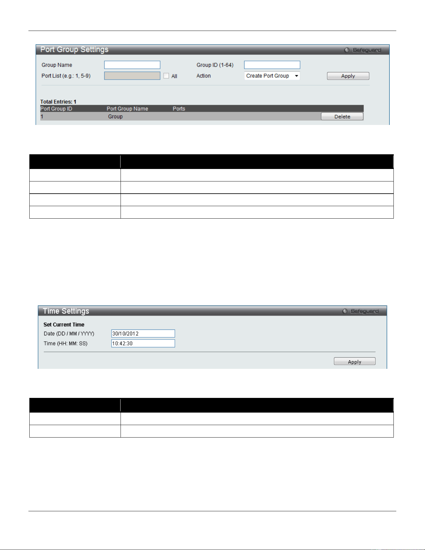
xStack® DGS-3420 Series Layer 2 Managed Stackable Gigabit Switch Web UI Reference Guide
33
Figure 2-27 Port Group Settings window
The fields that can be configured are described below:
Parameter
Description
Group Name
Enter the name of a port group.
Group ID (1-64)
Enter the ID of a port group
Port List
Enter a port or list of ports. Tick the All check box to apply to all ports.
Action
Use the drop-down menu to select Create Port Group, Add Ports or Delete Ports.
Click the Apply button to accept the changes made.
Click the Delete button to remove the specific entry.
Time Settings
Users can configure the time settings for the Switch.
To view the following window, click System Configuration > Time Settings, as show below:
Figure 2-28 Time Settings window
The fields that can be configured are described below:
Parameter Description
Date (DD/MM/YYYY)
Enter the current day, month, and year to update the system clock.
Time (HH:MM:SS)
Enter the current time in hours, minutes, and seconds.
Click the Apply button to accept the changes made.
User Accounts Settings
The Switch allows the control of user privileges.
To view the following window, click System Configuration > User Accounts Settings, as show below:
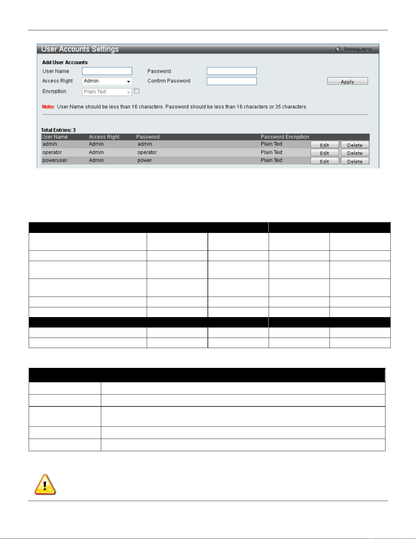
xStack® DGS-3420 Series Layer 2 Managed Stackable Gigabit Switch Web UI Reference Guide
34
Figure 2-29 User Accounts Settings window
To add a new user, type in a User Name and New Password and retype the same password in the Confirm New
Password field. Choose the level of privilege (Admin, Operator, Power User or User) from the Access Right drop-down
menu.
Management
Admin
Operator
Power User
User
Configuration Read/Write Read/Write–
partly
Read/Write–
partly
No
Network Monitoring
Read/Write
Read/Write
Read-only
Read-only
Community Strings and Trap
Stations
Read/Write Read-only Read-only Read-only
Update Firmware and Configuration
Files
Read/Write No No No
System Utilities
Read/Write
Read-only
Read-only
Read-only
Factory Reset
Read/Write
No
No
No
User Account Management
Add/Update/Delete User Accounts
Read/Write
No
No
No
View User Accounts
Read/Write
No
No
No
The fields that can be configured are described below:
Parameter Description
User Name
Enter a new user name for the Switch.
Access Right
Specify the access right for this user.
Encryption Specifies that encryption will be applied to this account. Option to choose from are Plain
Text, and SHA-1.
Password
Enter a new password for the Switch.
Confirm Password
Re-type in a new password for the Switch.
Click the Apply button to accept the changes made.
NOTICE: In case of lost passwords or password corruption, refer to Appendix A - Password Recovery
Procedure which will guide you through the steps necessary to resolve this issue.
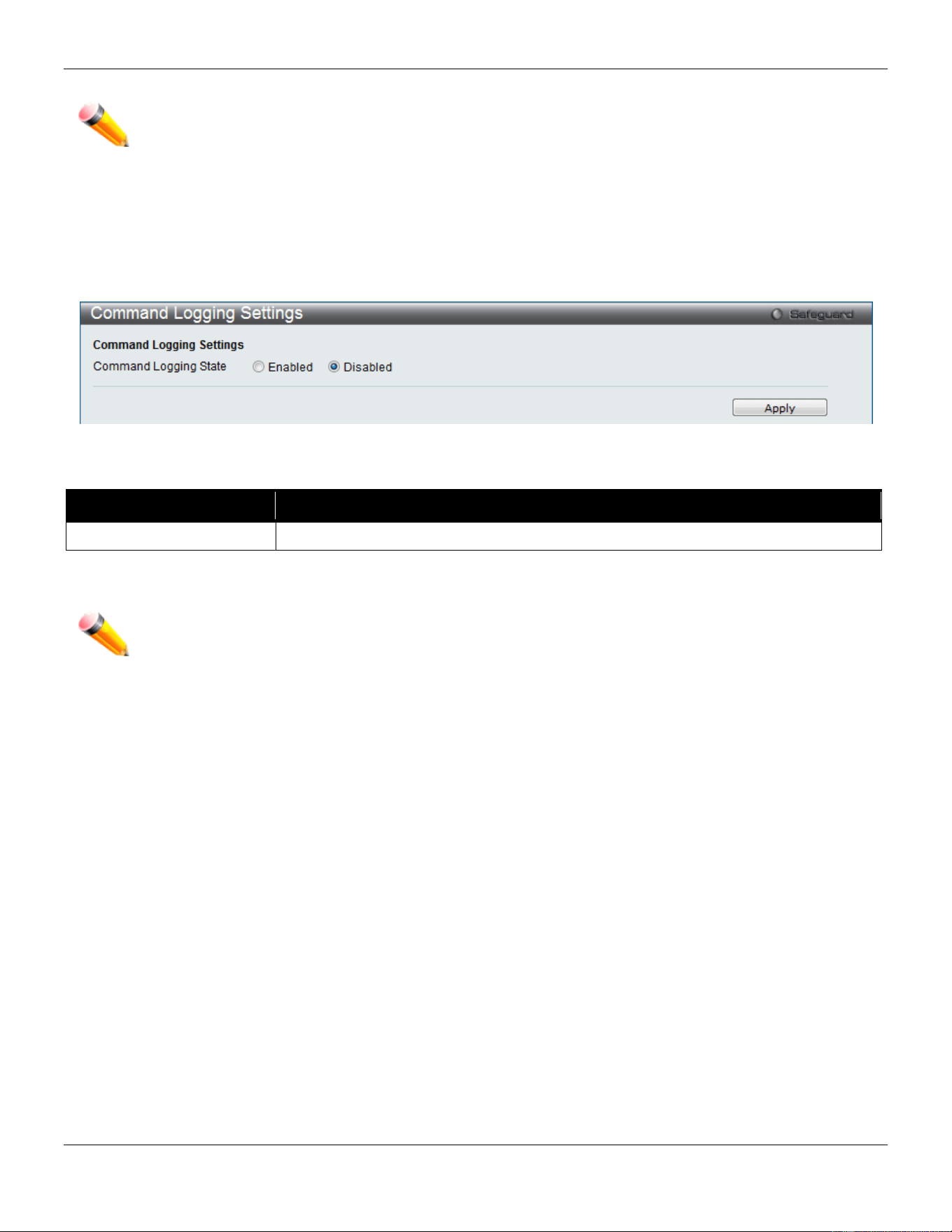
xStack® DGS-3420 Series Layer 2 Managed Stackable Gigabit Switch Web UI Reference Guide
35
NOTE: User Name should be less than 16 characters. Password should be less than 16 or 35 characters.
Command Logging Settings
This window is used to enable or disable the command logging settings.
To view this window, click System Configuration > Command Logging Settings, as shown below:
Figure 2-30 Command Logging Settings window
The fields that can be configured are described below:
Parameter Description
Command Logging State
Use the radio buttons to enable or disable the function.
Click the Apply button to accept the changes made.
NOTE: When the switch is under the booting or executing downloaded configuration procedure, all
configuration commands will not be logged. When the user uses AAA authentication to logged in,
the user name should not be changed if the user has used the Enable Admin function to replace
its privilege.
Stacking
From firmware release v1.00 of this Switch, the Switch now supports switch stacking, where a set of 12 switches can
be combined to be managed by one IP address through Telnet, the GUI interface (web), the console port or through
SNMP. Each switch of this series has two stacking ports which can be used to connect to other devices and make
them stack together.
Duplex Chain – As shown in Figure 2-31, The Duplex Chain topology stacks switches together in a chain-link format.
Using this method, data transfer is only possible in one direction and if there is a break in the chain, then data transfer
will obviously be affected.
Duplex Ring – As shown in Figure 2-32, the Duplex Ring stacks switches in a ring or circle format where data can be
transferred in two directions. This topology is very resilient due to the fact that if there is a break in the ring, data can
still be transferred through the stacking cables between switches in the stack.
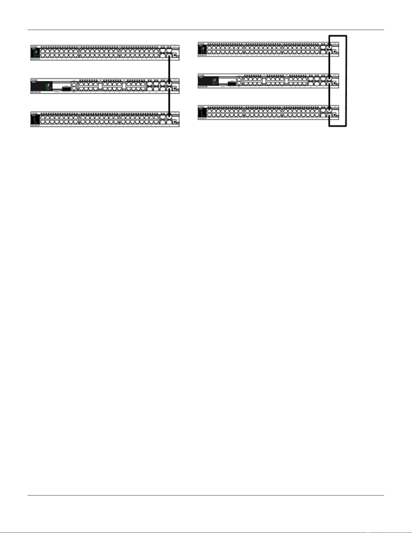
xStack® DGS-3420 Series Layer 2 Managed Stackable Gigabit Switch Web UI Reference Guide
36
Figure 2-31 Switches stacked in a Duplex Chain Figure 2-32 Switches stacked in a Duplex Ring
Within each of these topologies, each switch plays a role in the Switch stack. These roles can be set by the user per
individual Switch, or if desired, can be automatically determined by the Switch stack. Three possible roles exist when
stacking with the Switch.
Primary Master – The Primary Master is the leader of the stack. It will maintain normal operations, monitor operations
and the running topology of the Stack. This switch will also assign Stack Unit IDs, synchronize configurations and
transmit commands to remaining switches in the switch stack. The Primary Master can be manually set by assigning
this Switch the highest priority (a lower number denotes a higher priority) before physically assembling the stack, or it
can be determined automatically by the stack through an election process which determines the lowest MAC address
and then will assign that switch as the Primary Master, if all priorities are the same. The Primary master are physically
displayed by the seven segment LED to the far right on the front panel of the switch where this LED will flash between
its given Box ID and ‘H’.
Backup Master – The Backup Master is the backup to the Primary Master, and will take over the functions of the
Primary Master if the Primary Master fails or is removed from the Stack. It also monitors the status of neighboring
switches in the stack, will perform commands assigned to it by the Primary Master and will monitor the running status
of the Primary Master. The Backup Master can be set by the user by assigning this Switch the second highest priority
before physically assembling the stack, or it can be determined automatically by the stack through an election process
which determines the second lowest MAC address and then will assign that switch as the Backup Master, if all
priorities are the same. The Backup master are physically displayed by the seven segment LED to the far right on the
front panel of the switch where this LED will flash between its given Box ID and ‘h’.
Slave – Slave switches constitute the rest of the switch stack and although not Primary or Backup Masters, they can
be placed into these roles when these other two roles fail or are removed from the stack. Slave switches perform
operations requested by the master, monitor the status of neighbor switches in the stack and the stack topology and
adhere to the Backup Master’s commands once it becomes a Primary Master. Slave switches will do a self-check to
determine if it is to become the Backup Master if the Backup Master is promoted to the Primary Master, or if the
Backup Master fails or is removed from the switch stack. If both Primary and Backup masters fail, or are removed from
the Switch stack, it will determine if it is to become the Primary Master. These roles will be determined, first by priority
and if the priority is the same, the lowest MAC address.
Once switches have been assembled in the topology desired by the user and powered on, the stack will undergo three
processes until it reaches a functioning state.
Initialization State – This is the first state of the stack, where the runtime codes are set and initialized and the system
conducts a peripheral diagnosis to determine each individual switch is functioning properly.
Master Election State – Once the codes are loaded and initialized, the stack will undergo the Master Election State
where it will discover the type of topology used, elect a Primary Master and then a Backup Master.
Synchronization State – Once the Primary Master and the Backup Master have been established, the Primary Master
will assign Stacking Unit IDs to switches in the stack, synchronize configurations for all switches and then transmit
commands to the rest of the switches based on the users configurations of the Primary Master.
Once these steps have been completed, the switch stack will enter a normal operating mode.
Stack Switch Swapping
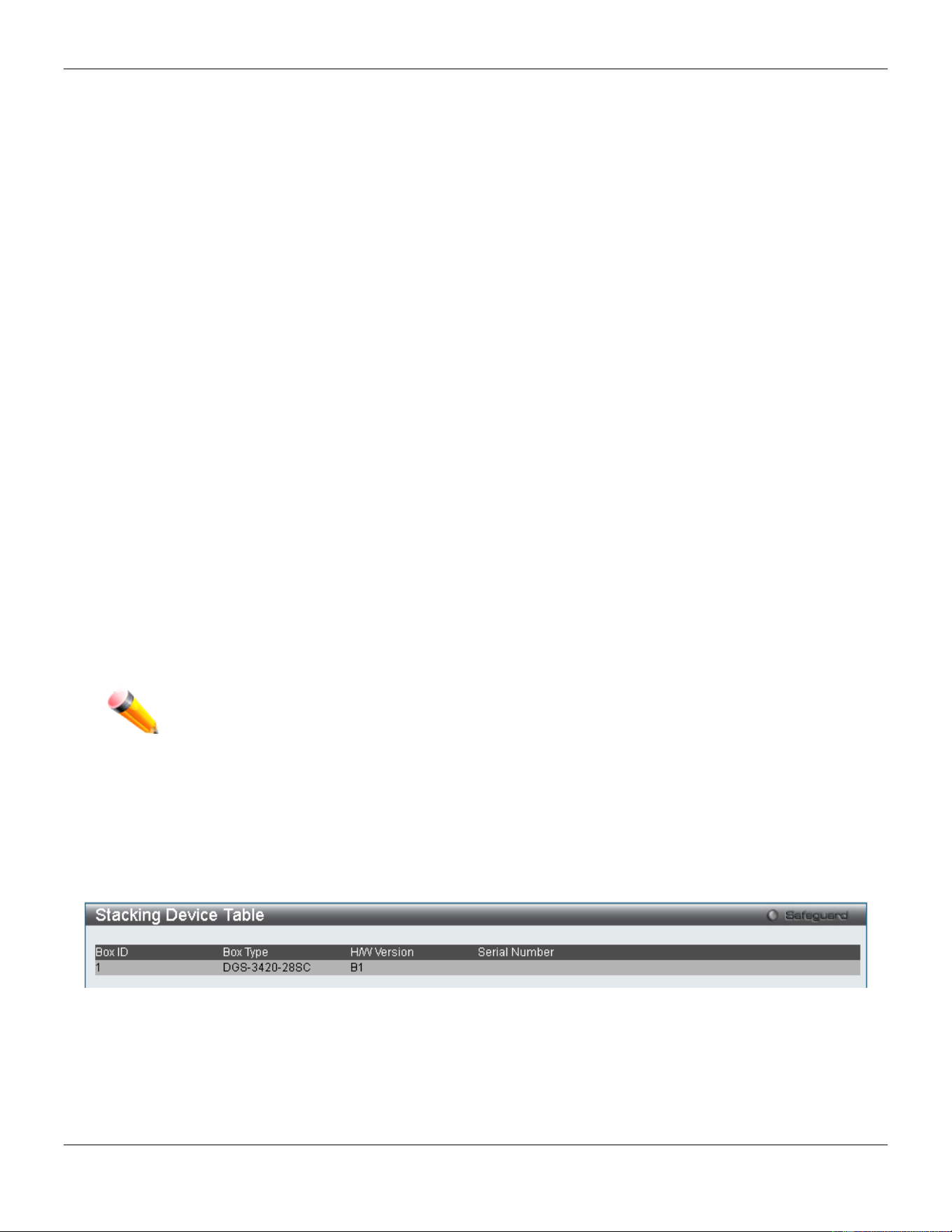
xStack® DGS-3420 Series Layer 2 Managed Stackable Gigabit Switch Web UI Reference Guide
37
The stacking feature of the Switch supports “hot swapping” of switches in and out of the running stack. Users may
remove or add switches to the stack without powering down or largely affecting the transfer of data between switches
in the stack, with a few minor provisions.
When switches are “hot inserted” into the running stack, the new switch may take on the Primary Master, Backup
Master or Slave role, depending on configurations set on the newly added switch, such as configured priority or MAC
address. Yet, if adding two stacks together that have both previously undergone the election process, and therefore
both have a Primary Master and a Backup master, a new Primary Master will be elected from one of the already
existing Primary Masters, based on priority or MAC address. This Primary Master will take over all of the Primary
Master’s roles for all new switches that were hot inserted. This process is done using discovery packets that circulate
through the switch stack every 1.5 seconds until the discovery process has been completed.
The “hot remove” action means removing a device from the stack while the stack is still running. The hot removal is
detected by the stack when it fails to receive heartbeat packets during its specified interval from a device, or when one
of the stacking ports links is down. Once the device has been removed, the remaining switches will update their
stacking topology database to reflect the change. Any one of the three roles, Primary Master, Backup Master or Slave,
may be removed from the stack, yet different processes occur for each specific device removal.
If a Slave device has been removed, the Primary Master will inform other switches of the hot remove of this device
through the use of unit leave messages. Switches in the stack will clear the configurations of the unit removed, and
dynamically learned databases, such as ARP, will be cleared as well.
If the Backup Master has been hot removed, a new Backup Master will be chosen through the election process
previously described. Switches in the stack will clear the configurations of the unit removed, and dynamically learned
databases, such as ARP, will be cleared as well. Then the Backup Master will begin backing up the Primary Master
when the database synchronization has been completed by the stack.
If the Primary Master is removed, the Backup Master will assume the Primary Master’s role and a new Backup Master
will be chosen using the election process. Switches in the stack will clear the configurations of the unit removed, and
dynamically learned databases, such as ARP, will be cleared as well. The new Primary Master will inherit the MAC and
IP address of the previous Primary Master to avoid conflict within the stack and the network itself.
If both the Primary Master and the Backup Master are removed, the election process is immediately processed and a
new Primary Master and Backup Master is determined. Switches in the stack will clear the configurations of the units
removed, and dynamically learned databases, such as ARP, will be cleared as well. Static switch configurations still
remain in the database of the remaining switches in the stack and those functions will not be affected.
NOTE: If there is a Box ID conflict when the stack is in the discovery phase, the device will enter
a special standalone topology mode. Users can only get device information, configure
Box IDs, save and reboot. All stacking ports will be disabled and an error message will be
produced on the local console port of each device in the stack. Users must reconfigure
Box IDs and reboot the stack.
Stacking Device Table
This window is used to display the current devices in the Switch Stack.
To view this window, click System Configuration > Stacking > Stacking Device Table, as shown below:
Figure 2-33 Stacking Device Table window
Stacking Mode Settings
To begin the stacking process, users must first enable this device for stacking by using the Stacking Mode Settings
window.
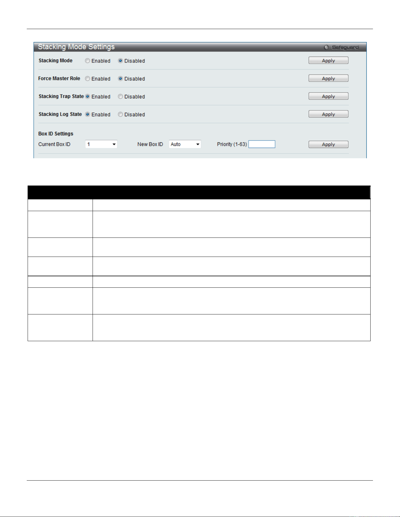
xStack® DGS-3420 Series Layer 2 Managed Stackable Gigabit Switch Web UI Reference Guide
38
To view this window, click System Configuration > Stacking > Stacking Mode Settings, as shown below:
Figure 2-34 Stacking Mode Settings window
The fields that can be configured or viewed are described below:
Parameter Description
Stacking Mode
The stacking mode is disabled by default.
Force Master Role
Use the radio buttons to enable or disable the function. It is used to ensure the master role is
unchanged when adding a new device to the current stacking topology. If the Enabled radio
button is selected, the master’s priority will become zero after the stacking has stabilized.
Stacking Trap
State
Specifies that the traps will be sent for stacking.
Stacking Log
State
Specifies that the logs will be sent for stacking.
Current Box ID
The Box ID of the switch in the stack to be configured.
New Box ID
The new box ID of the selected switch in the stack that was selected in the Current Box ID
field. The user may choose any number between 1 and 12 to identify the switch in the switch
stack. Auto will automatically assign a box number to the switch in the switch stack.
Priority (1-63)
Displays the priority ID of the Switch. The lower the number, the higher the priority. The box
(switch) with the lowest priority number in the stack is the Primary Master switch. The Primary
Master switch will be used to configure applications of the switch stack.
Click the Apply button to accept the changes made.
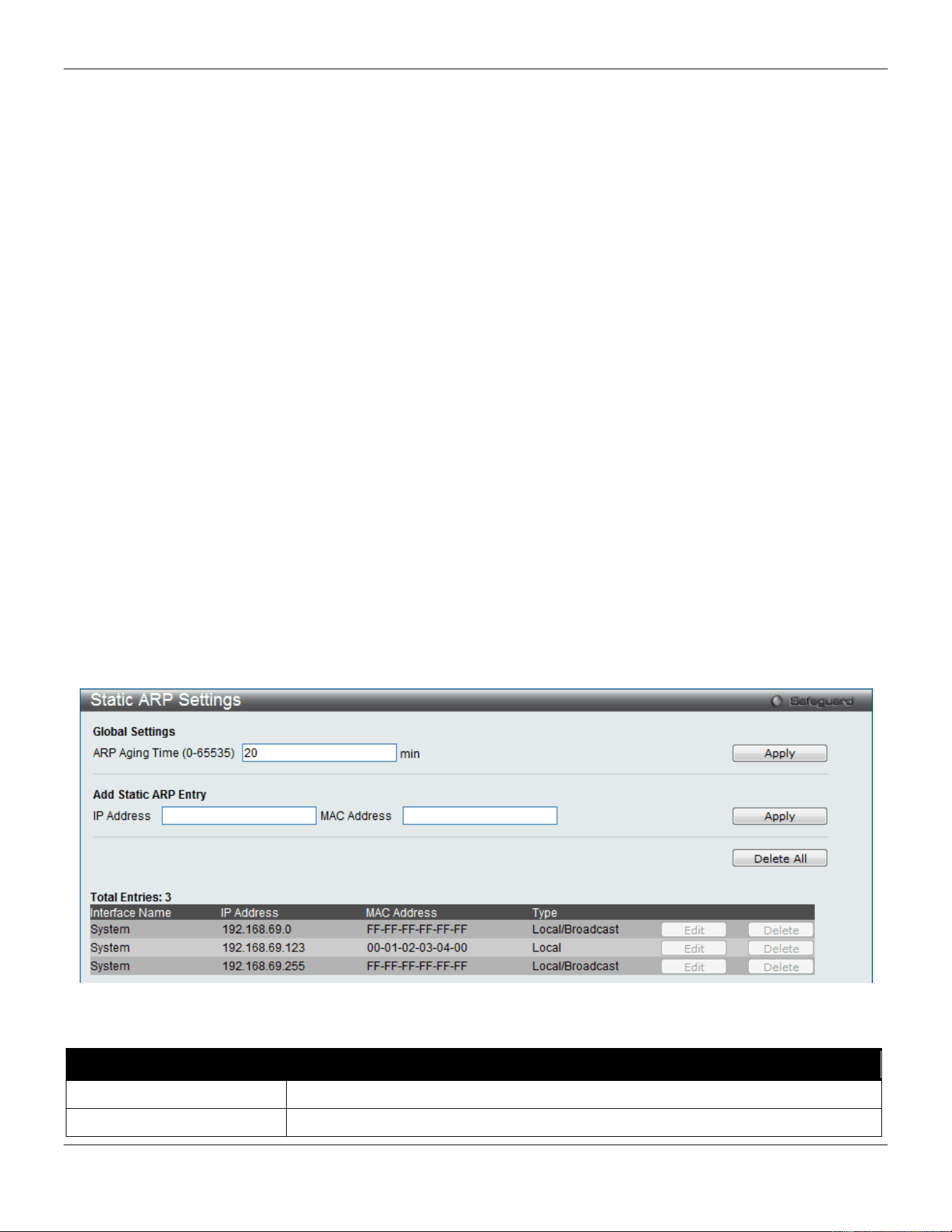
xStack® DGS-3420 Series Layer 2 Managed Stackable Gigabit Switch Web UI Reference Guide
39
Chapter 3 Management
ARP
Gratuitous ARP
IPv6 Neighbor Settings
IP Interface
Management Settings
Out of Band Management Settings
Session Table
Single IP Management
SNMP Settings
Telnet Settings
Web Settings
Power Saving
ARP
Static ARP Settings
The Address Resolution Protocol is a TCP/IP protocol that converts IP addresses into physical addresses. This table
allows network managers to view, define, modify, and delete ARP information for specific devices. Static entries can be
defined in the ARP table. When static entries are defined, a permanent entry is entered and is used to translate IP
addresses to MAC addresses.
To view the following window, click Management > ARP > Static ARP Settings, as show below:
Figure 3-1 Static ARP Settings window
The fields that can be configured are described below:
Parameter Description
ARP Aging Time (0-65535)
The ARP entry age-out time, in minutes. The default is 20 minutes.
IP Address
The IP address of the ARP entry.
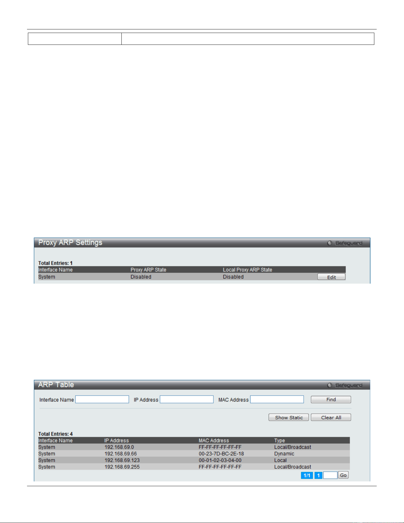
xStack® DGS-3420 Series Layer 2 Managed Stackable Gigabit Switch Web UI Reference Guide
40
MAC Address
The MAC address of the ARP entry.
Click the Apply button, located in the Global Settings section to accept the changes made in this section.
Click the Apply button, located in the Add Static ARP Entry section to accept the changes made in this section.
Click the Delete All button to remove all the entries listed.
Click the Edit button to re-configure the specific entry.
Click the Delete button to remove the specific entry.
Proxy ARP Settings
The Proxy ARP (Address Resolution Protocol) feature of the Switch will allow the Switch to reply to ARP requests
destined for another device by faking its identity (IP and MAC Address) as the original ARP responder. Therefore, the
Switch can then route packets to the intended destination without configuring static routing or a default gateway.
The host, usually a layer 3 switch, will respond to packets destined for another device. For example, if hosts A and B
are on different physical networks, B will not receive ARP broadcast requests from A and therefore cannot respond.
Yet, if the physical network of A is connected by a router or layer 3 switch to B, the router or Layer 3 switch will see the
ARP request from A.
This local proxy ARP function allows the Switch to respond to the proxy ARP, if the source IP and destination IP are in
the same interface.
To view the following window, click Management > ARP > Proxy ARP Settings, as show below:
Figure 3-2 Proxy ARP Settings window
Click the Edit button to re-configure the specific entry and select the proxy ARP state of the IP interface. By default,
both the Proxy ARP State and Local Proxy ARP State are disabled.
ARP Table
Users can display current ARP entries on the Switch.
To view the following window, click Management > ARP > ARP Table, as show below:
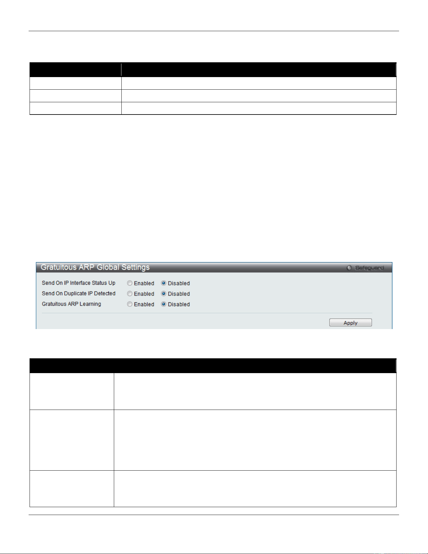
xStack® DGS-3420 Series Layer 2 Managed Stackable Gigabit Switch Web UI Reference Guide
41
Figure 3-3 ARP Table window
The fields that can be configured are described below:
Parameter Description
Interface Name
Enter or view the Interface name used.
IP Address
Enter or view the IP Address used.
MAC Address
Enter or view the MAC Address used.
Click the Find button to locate a specific entry based on the information entered.
Click the Show Static button to display only the static entries in the display table.
Click the Clear All button to remove all the entries listed in the table.
Enter a page number and click the Go button to navigate to a specific page when multiple pages exist.
Gratuitous ARP
Gratuitous ARP Global Settings
The user can enable or disable the gratuitous ARP global settings here.
To view the following window, click Management > Gratuitous ARP > Gratuitous ARP Global Settings, as show
below:
Figure 3-4 Gratuitous ARP Global Settings Window
The fields that can be configured are described below:
Parameter Description
Send On IP Interface
Status Up
The command is used to enable/disable sending of gratuitous ARP request packet while
the IPIF interface become up. This is used to automatically announce the interface’s IP
address to other nodes. By default, the state is disabled, and only one gratuitous ARP
packet will be broadcast.
Send On Duplicate IP
Detected
The command is used to enable/disable the sending of gratuitous ARP request packet
while a duplicate IP is detected. By default, the state is disabled. For this command, the
duplicate IP detected means that the system received an ARP request packet that is
sent by an IP address that match the system’s own IP address. In this case, the system
knows that somebody out there uses an IP address that is conflict with the system. In
order to reclaim the correct host of this IP address, the system can send out the
gratuitous ARP request packets for this duplicate IP address.
Gratuitous ARP
Learning
Normally, the system will only learn the ARP reply packet or a normal ARP request
packet that asks for the MAC address that corresponds to the system’s IP address. The
command is used to enable/disable learning of ARP entry in ARP cache based on the
received gratuitous ARP packet. The gratuitous ARP packet is sent by a source IP
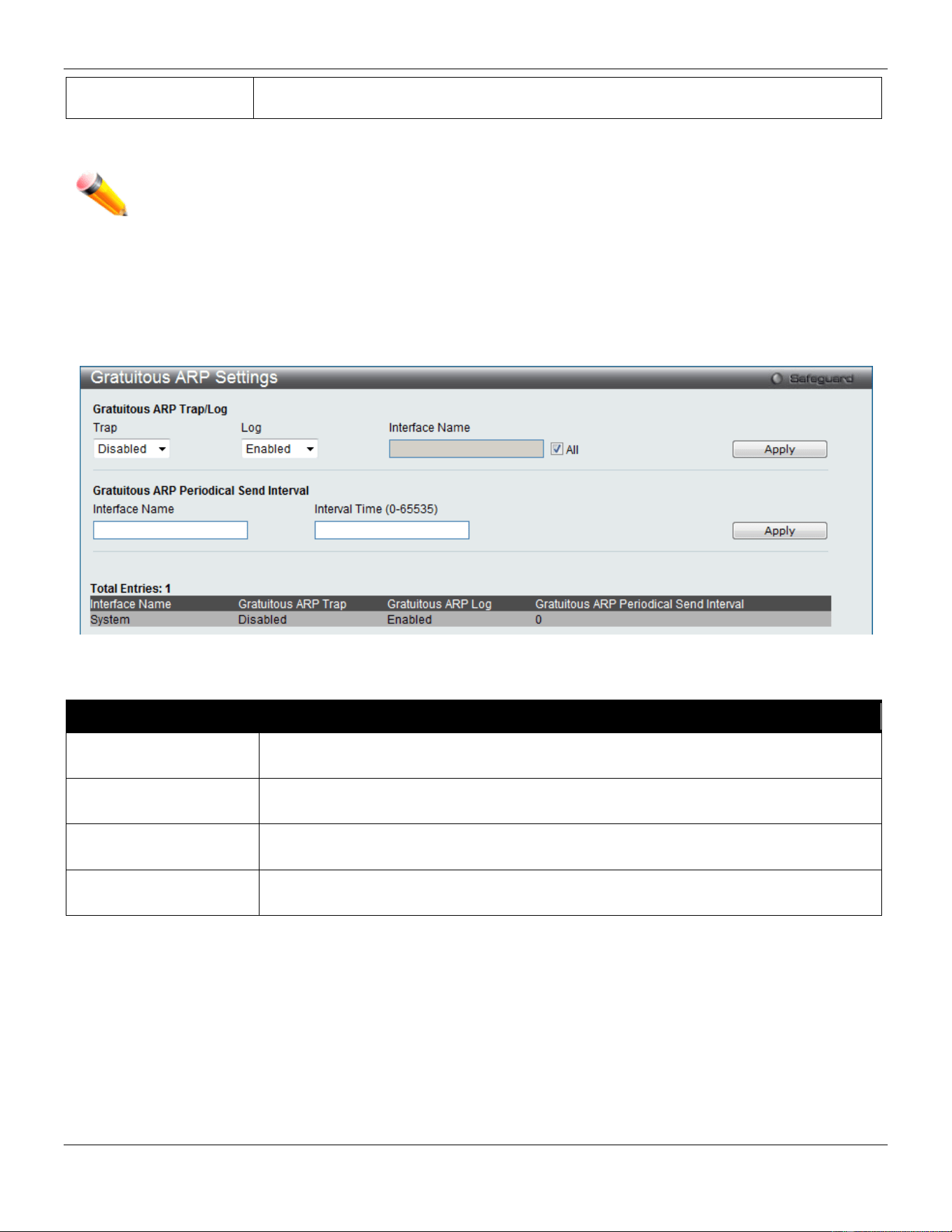
xStack® DGS-3420 Series Layer 2 Managed Stackable Gigabit Switch Web UI Reference Guide
42
address that is identical to the IP that the packet is queries for. By default, the state is
Disabled status.
Click the Apply button to accept the changes made.
NOTE: With the gratuitous ARP learning, the system will not learn new entry but only do the update on
the ARP table based on the received gratuitous ARP packet.
Gratuitous ARP Settings
The user can configure the IP interface’s gratuitous ARP parameter.
To view the following window, click Management > Gratuitous ARP > Gratuitous ARP Settings, as show below:
Figure 3-5 Gratuitous ARP Settings window
The fields that can be configured are described below:
Parameter Description
Trap
Use the drop-down menu to enable or disable the trap option. By default the trap is
disabled.
Log
Use the drop-down menu to enable or disable the logging option. By default the event
log is enabled.
Interface Name Enter the interface name of the Layer 3 interface. Select All to enable or disable
gratuitous ARP trap or log on all interfaces.
Interval Time (0-65535)
Enter the periodically send gratuitous ARP interval time in seconds. 0 means that
gratuitous ARP request will not be sent periodically. By default the interval time is 0.
Click the Apply button, located in the Gratuitous ARP Trap/Log section to accept the changes made in this section.
Click the Apply button, located in the Gratuitous ARP Periodical Send Interval section to accept the changes made
in this section.
IPv6 Neighbor Settings
The user can configure the Switch’s IPv6 neighbor settings. The Switch’s current IPv6 neighbor settings will be
displayed in the table at the bottom of this window.
To view the following window, click Management > IPv6 Neighbor Settings, as show below:
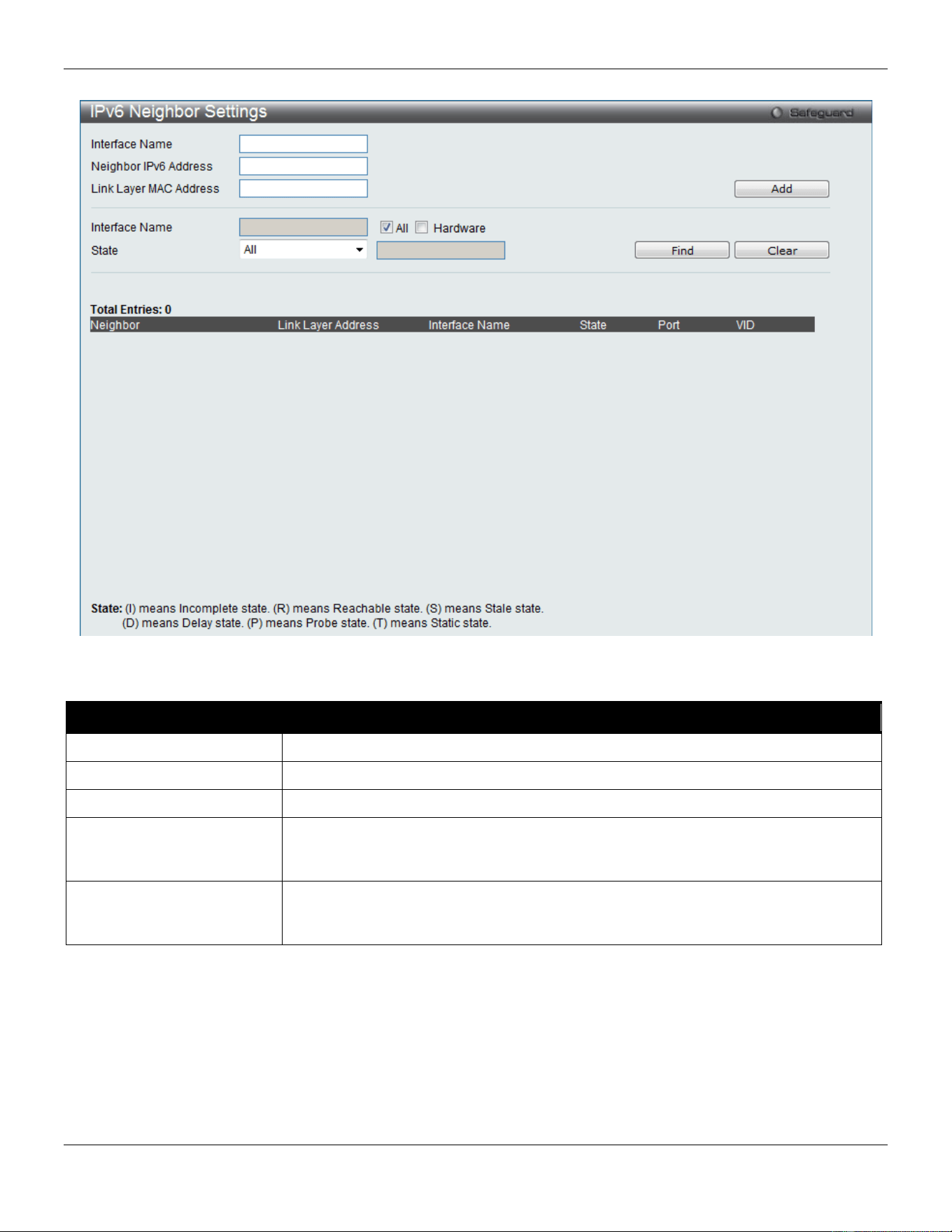
xStack® DGS-3420 Series Layer 2 Managed Stackable Gigabit Switch Web UI Reference Guide
43
Figure 3-6 IPv6 Neighbor Settings window
The fields that can be configured are described below:
Parameter Description
Interface Name
Enter the interface name of the IPv6 neighbor.
Neighbor IPv6 Address
Enter the neighbor IPv6 address.
Link Layer MAC Address
Enter the link layer MAC address.
Interface Name Enter the interface name of the IPv6 neighbor. Tick the All check box to search for
all current interfaces on the Switch. Tick the Hardware check box to display all the
neighbor cache entries which were written into the hardware table.
State
Use the drop-down menu to select All, Address, Static, or Dynamic. When the user
selects address from the drop-down menu, the user will be able to enter an IPv6
address in the space provided next to the state option.
Click the Add button to add a new entry based on the information entered.
Click the Find button to locate a specific entry based on the information entered.
Click the Clear button to clear all the information entered in the fields.
IP Interface
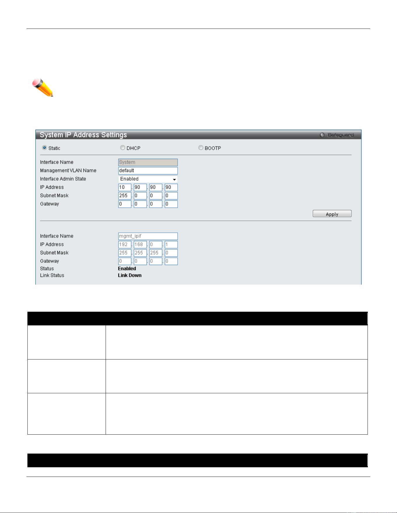
xStack® DGS-3420 Series Layer 2 Managed Stackable Gigabit Switch Web UI Reference Guide
44
System IP Address Settings
The IP address may initially be set using the console interface prior to connecting to it through the Ethernet. The Web
manager will display the Switch’s current IP settings.
NOTE: The Switch’s factory default IP address is 10.90.90.90 with a subnet mask of 255.0.0.0 and a
default gateway of 0.0.0.0.
To view the following window, click Management > IP Interface > System IP Address Settings, as show below:
Figure 3-7 System IP Address Settings window
The fields that can be configured are described below:
Parameter Description
Static
Allow the entry of an IP address, subnet mask, and a default gateway for the Switch.
These fields should be of the form xxx.xxx.xxx.xxx, where each xxx is a number
(represented in decimal form) between 0 and 255. This address should be a unique
address on the network assigned for use by the network administrator.
DHCP
The Switch will send out a DHCP broadcast request when it is powered up. The DHCP
protocol allows IP addresses, network masks, and default gateways to be assigned by a
DHCP server. If this option is set, the Switch will first look for a DHCP server to provide it
with this information before using the default or previously entered settings.
BOOTP
The Switch will send out a BOOTP broadcast request when it is powered up. The
BOOTP protocol allows IP addresses, network masks, and default gateways to be
assigned by a central BOOTP server. If this option is set, the Switch will first look for a
BOOTP server to provide it with this information before using the default or previously
entered settings.
The following table will describe the fields that are about the System Interface.
Parameter Description
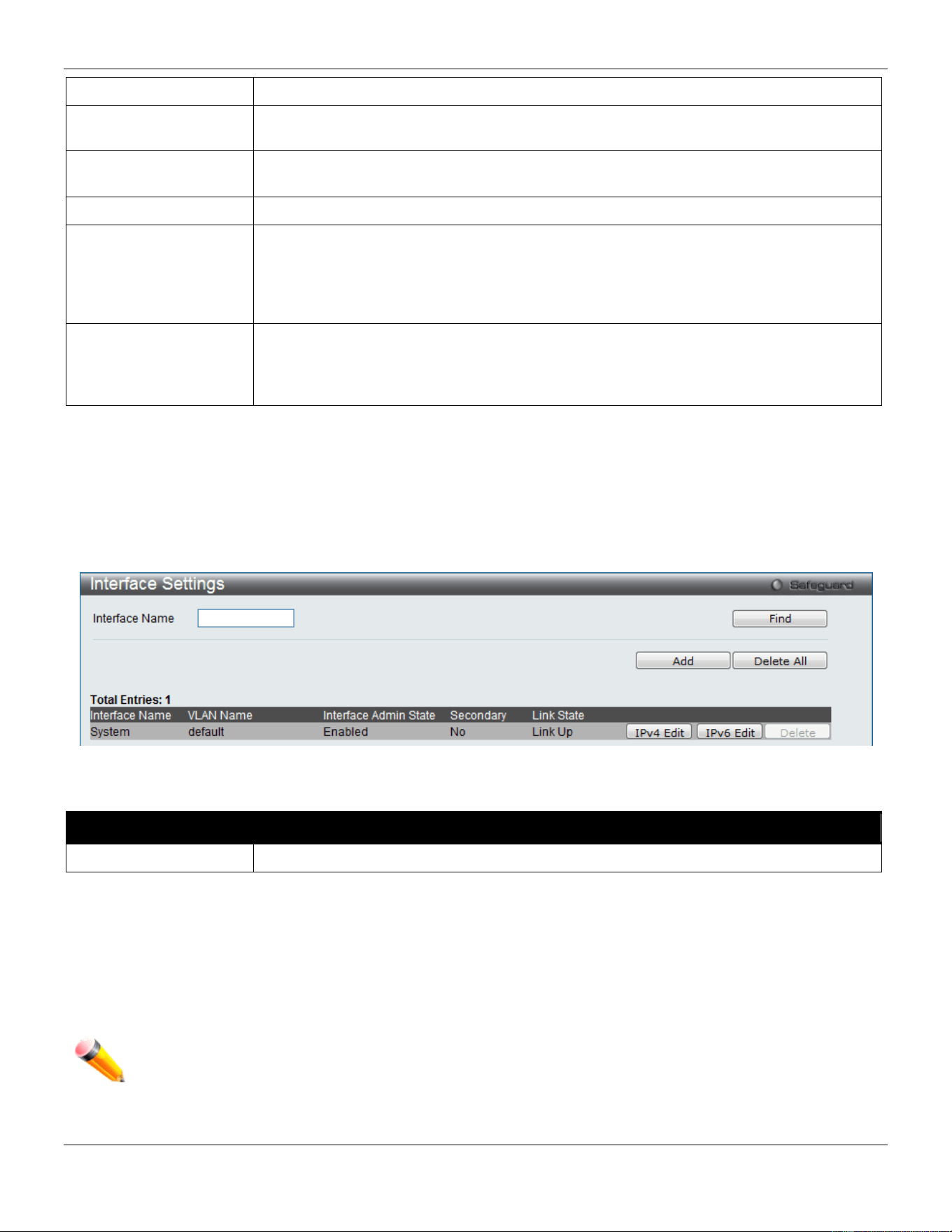
xStack® DGS-3420 Series Layer 2 Managed Stackable Gigabit Switch Web UI Reference Guide
45
Interface Name
Display the System interface name.
Management VLAN
Name
This allows the entry of a VLAN name that belongs to the System interface.
Interface Admin State
Use the drop-down menu to enable or disable the configuration on this interface. If the
state is disabled, the IP interface cannot be accessed.
IP Address
This field allows the entry of an IPv4 address to be assigned to this IP interface.
Subnet Mask
A Bitmask that determines the extent of the subnet that the Switch is on. Should be of
the form xxx.xxx.xxx.xxx, where each xxx is a number (represented in decimal) between
0 and 255. The value should be 255.0.0.0 for a Class A network, 255.255.0.0 for a Class
B network, and 255.255.255.0 for a Class C network, but custom subnet masks are
allowed.
Gateway
IP address that determines where packets with a destination address outside the current
subnet should be sent. This is usually the address of a router or a host acting as an IP
gateway. If your network is not part of an intranet, or you do not want the Switch to be
accessible outside your local network, you can leave this field unchanged.
Click the Apply button to accept the changes made.
Interface Settings
Users can display the Switch’s current IP interface settings.
To view the following window, click Management > IP Interface > Interface Settings, as show below:
Figure 3-8 Interface Settings window
The fields that can be configured are described below:
Parameter Description
Interface Name
Enter the name of the IP interface to search for.
Click the Find button to locate a specific entry based on the information entered.
Click the Add button to add a new entry based on the information entered.
Click the Delete All button to remove all the entries listed.
Click the IPv4 Edit button to edit the IPv4 settings for the specific entry.
Click the IPv6 Edit button to edit the IPv6 settings for the specific entry.
Click the Delete button to remove the specific entry.
NOTE: To create IPv6 interfaces, the user has to create an IPv4 interface then edit it to IPv6.
Click the Add button to see the following window.
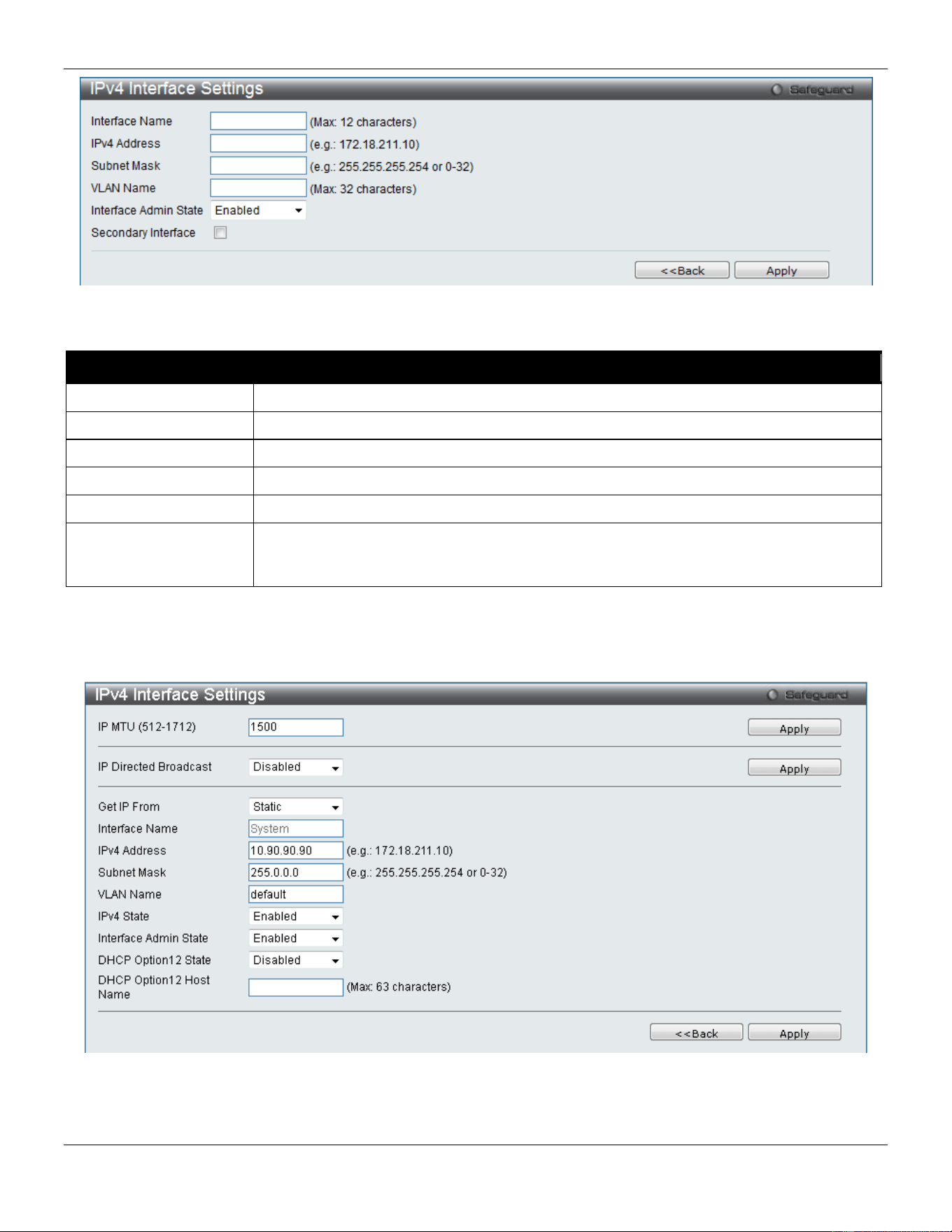
xStack® DGS-3420 Series Layer 2 Managed Stackable Gigabit Switch Web UI Reference Guide
46
Figure 3-9 IPv4 Interface Settings window
The fields that can be configured are described below:
Parameter Description
Interface Name
Enter the name of the IP interface being created.
IPv4 Address
Enter the IPv4 address used.
Subnet Mask
Enter the IPv4 subnet mask used.
VLAN Name
Enter the VLAN Name used.
Interface Admin State
Use the drop-down menu to enable or disable the Interface Admin State.
Secondary Interface
Tick the check box to use this Interface as a Secondary Interface. When the primary IP
is not available, the VLAN will switch to the secondary interface. It will switch back when
the primary IP was recovered.
Click the Apply button to accept the changes made.
Click the <<Back button to discard the changes made and return to the previous page.
Click the IPv4 Edit button to see the following window.
Figure 3-10 IPv4 Interface Settings – Edit window
The fields that can be configured are described below:
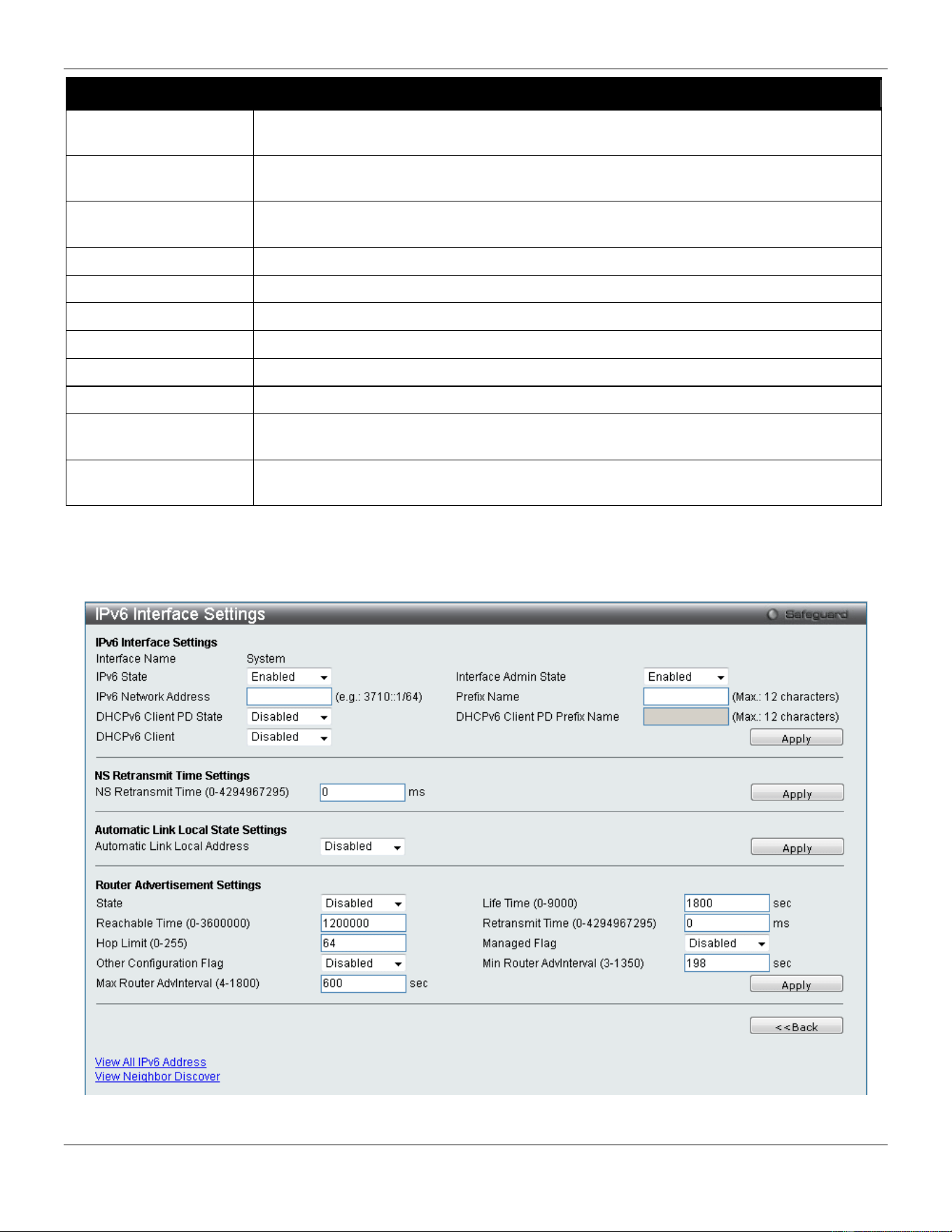
xStack® DGS-3420 Series Layer 2 Managed Stackable Gigabit Switch Web UI Reference Guide
47
Parameter Description
IP MTU (512-1712)
Enter the IP Layer MTU value used. The value is between 512 and 1712. The default
value is 1500.
IP Directed Broadcast
Select the IP directed broadcast option. This specifies to enable or disable the IP
directed-broadcast state of a specified interface.
Get IP From
Use the drop-down menu to specify the method that this Interface uses to acquire an IP
address.
Interface Name
Enter the name of the IP interface being configured.
IPv4 Address
Enter the IPv4 address used.
Subnet Mask
Enter the IPv4 subnet mask used.
VLAN Name
Enter the VLAN Name used.
IPv4 State
Use the drop-down menu to enable or disable IPv4 State.
Interface Admin State
Use the drop-down menu to enable or disable the Interface Admin State.
DHCP Option 12 State
Use the drop-down menu to enable or disable insertion of option 12 in the
DHCPDISCOVER and DHCPREQUEST message.
DHCP Option 12 Host
Name
Enter the host name to be inserted in the DHCPDISCOVER and DHCPREQUEST
message.
Click the Apply button to accept the changes made for each individual section.
Click the <<Back button to discard the changes made and return to the previous page.
Click the IPv6 Edit button to see the following window.
Figure 3-11 IPv6 Interface Settings window

xStack® DGS-3420 Series Layer 2 Managed Stackable Gigabit Switch Web UI Reference Guide
48
The fields that can be configured or displayed are described below:
Parameter Description
Interface Name
Display the IPv6 interface name.
IPv6 State
Use the drop-down menu to enable or disable IPv6 State.
Interface Admin State
Use the drop-down menu to enable or disable the Interface Admin State.
IPv6 Network Address
Enter the interface’s global or link local address.
Prefix Name
Enter the IPv6 prefix name used here.
DHCPv6 Client PD State
Select to enable or disable the DHCPv6 client PD state of the interface.
DHCPv6 Client PD
Prefix Name
Enter the DHCPv6 client PD prefix name used here.
DHCPv6 Client
Select to enable or disable the DHCPv6 client option here.
NS Retransmit Time
(0-4294967295)
Enter the Neighbor solicitation’s retransmit timer in millisecond here. It has the same
value as the RA retransmit time in the config ipv6 nd ra command. If this field is
configured, it will duplicate the entry into the RA field.
Automatic Link Local
Address
Use the drop-down menu to enable or disable the Automatic Link Local Address.
State
Use the drop-down menu to enable or disable router advertisement.
Life Time (0-9000)
Enter the lifetime of the router between 0 and 9000 seconds as the default router.
Reachable Time (0-
3600000)
Enter the amount of time that a node can consider a neighboring node reachable after
receiving a reachability confirmation, in milliseconds.
Retransmit Time (0-
4294967295)
Enter the amount of time between retransmissions of router advertisement message in
millisecond, and the router advertisement packet will take it to host.
Hop Limit (0-255)
Enter the default value of the hop limit field in the IPv6 header for packets sent by
hosts that receive this RA message.
Managed Flag
Use the drop-down menu to enable or disable the function. When Enabled, it indicates
that hosts receiving this RA must use a stateful address configuration protocol to
obtain an address, in addition to the addresses derived from the stateless address
configuration. Set to Disabled to stop hosts receiving the RA from using a stateful
address configuration to obtain an address.
Other Configuration
Flag
Use the drop-down menu to enable or disable the function. When Enabled, it indicates
that hosts receiving this RA must use a stateful address configuration protocol to
obtain the address configuration information. Set to Disabled to stop hosts receiving
this RA from using a stateful address configuration protocol to obtain the address
configuration information.
Min Router AdvInterval
(3-1350)
Enter the minimum time allowed between sending unsolicited multicast Router
Advertisements from the interface, in seconds. It must be no less than 3 seconds and
no greater than .75 * MaxRtrAdvInterval. The default is 0.33 * MaxRtrAdvInterval.
Max Router AdvInterval
(4-1800)
Enter the maximum time allowed between sending unsolicited multicast Router
Advertisements from the interface, in seconds. It must be no less than 4 seconds and
no greater than 1800 seconds. The default is 600 seconds.
Click the Apply button to accept the changes made for each individual section.
Click the <<Back button to discard the changes made and return to the previous page.
Click the View All IPv6 Address link to view all the current IPv6 address.
Click the View Neighbor Discover link to view all IPv6 neighbor discover.
Click the View All IPv6 Address link to see the following window.
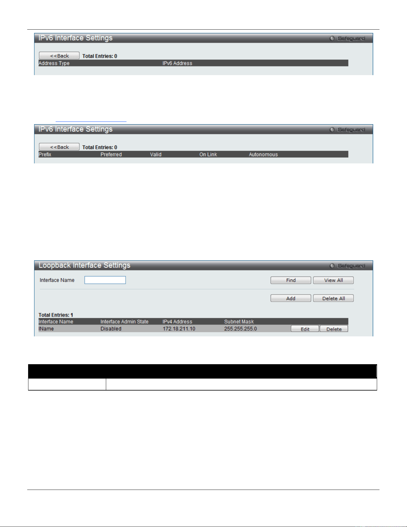
xStack® DGS-3420 Series Layer 2 Managed Stackable Gigabit Switch Web UI Reference Guide
49
Figure 3-12 IPv6 Interface Settings – View All IPv6 Address window
Click the <<Back button to return to the previous page.
Click the View Neighbor Discover link to see the following window.
Figure 3-13 IPv6 Interface Settings – View Neighbor Discover window
Click the <<Back button to return to the previous page.
Loopback Interface Settings
This window is used to configure loopback interfaces. A loopback interface is a logical IP interface which is always
active, until a user disables or deletes it. It is independent of the state of any physical interfaces.
To view this window, click Management > IP Interface > Loopback Interfaces Settings, as show below:
Figure 3-14 Loopback Interface Settings window
The fields that can be configured are described below:
Parameter Description
Interface Name
Enter an interface name.
Click the Find button to locate a specific entry based on the information entered.
Click the View All button to display all the existing entries.
Click the Add button to create a new entry.
Click the Delete All button to remove all the entries listed in the table.
Click the Edit button to re-configure the specific entry.
Click the Delete button to remove the specific entry.
Click the Add or Edit button to see the following window.
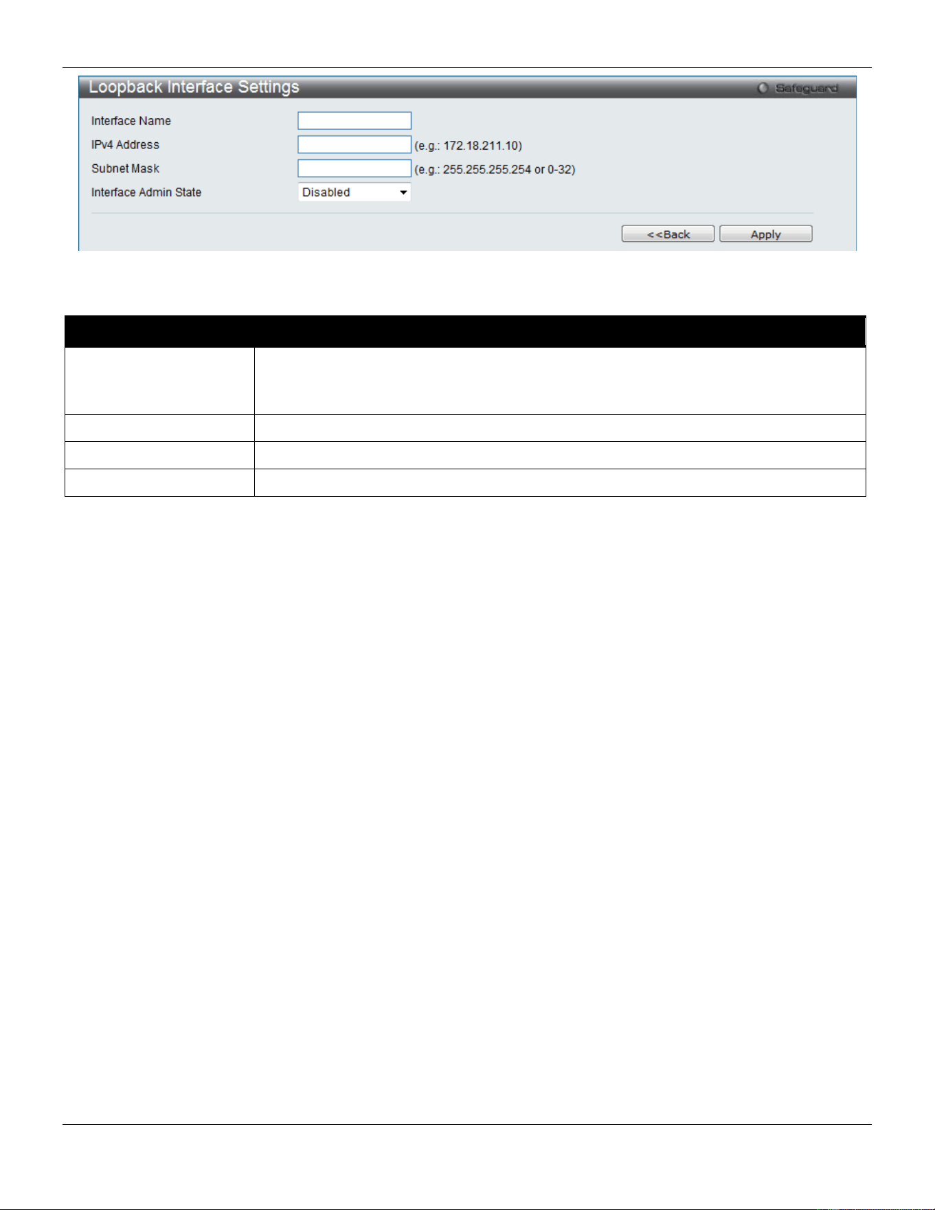
xStack® DGS-3420 Series Layer 2 Managed Stackable Gigabit Switch Web UI Reference Guide
50
Figure 3-15 Loopback Interface Settings - Add/Edit window
The fields that can be configured are described below:
Parameter Description
Interface Name
The name of the loopback interface.
NOTE: The loopback ipif has the same name domain space with the regular ipif, so its
name can’t be a duplicate with the regular ipif.
IPv4 Address
Enter a 32-bit IPv4 address for the loopback interface.
Subnet Mask
Enter a subnet mask to be applied to the loopback interface.
Interface Admin State
Use the drop-down menu to enable or disable the loopback interface.
Click the Apply button to accept the changes made for each individual section.
Click the <<Back button to discard the changes made and return to the previous page.
Management Settings
Users can stop the scrolling of multiple pages beyond the limits of the console when using the Command Line Interface.
This window is also used to enable the DHCP auto configuration feature on the Switch. When enabled, the Switch is
instructed to receive a configuration file from a TFTP server, which will set the Switch to become a DHCP client
automatically on boot-up. To employ this method, the DHCP server must be set up to deliver the TFTP server IP
address and configuration file name information in the DHCP reply packet. The TFTP server must be up and running
and hold the necessary configuration file stored in its base directory when the request is received from the Switch. For
more information about loading a configuration file for use by a client, see the DHCP server and/or TFTP server
software instructions. The user may also consult the Upload Log File window description located in the Tools section
of this manual.
If the Switch is unable to complete the DHCP auto configuration, the previously saved configuration file present in the
Switch’s memory will be used.
Users can also configure Password Encryption on the Switch.
To view the following window, click Management > Management Settings, as show below:
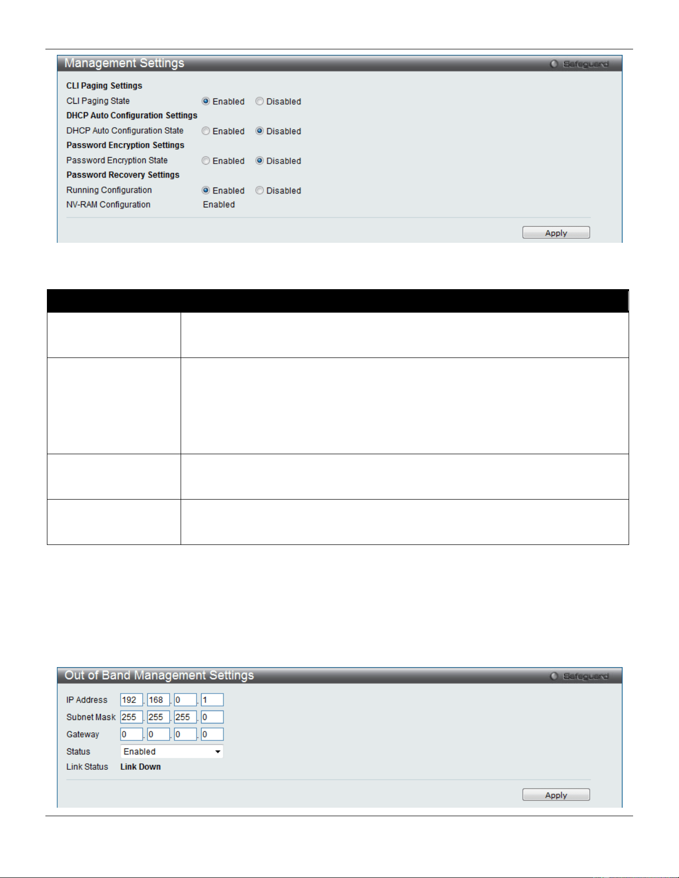
xStack® DGS-3420 Series Layer 2 Managed Stackable Gigabit Switch Web UI Reference Guide
51
Figure 3-16 Management Settings window
The fields that can be configured are described below:
Parameter Description
CLI Paging State
Command Line Interface paging stops each page at the end of the console. This allows
you to stop the scrolling of multiple pages of text beyond the limits of the console. CLI
Paging is Enabled by default. To disable it, click the Disabled radio button.
DHCP Auto
Configuration State
Enable or disable the Switch’s DHCP auto configuration feature. When enabled, the
Switch is instructed to receive a configuration file from a TFTP server, which will set the
Switch to become a DHCP client automatically on boot-up. To employ this method, the
DHCP server must be set up to deliver the TFTP server IP address and configuration file
name information in the DHCP reply packet. The TFTP server must be up and running
and hold the necessary configuration file stored in its base directory when the request is
received from the Switch.
Password Encryption
State
Password encryption will encrypt the password configuration in configuration files.
Password encryption is Disabled by default. To enable password encryption, click the
Enabled radio button.
Running Configuration
Under the Password Recovery option, the running configuration can be enabled or
disable. Being enabled, will allow the user to perform a password recovery of the running
configuration.
Click the Apply button to accept the changes made.
Out of Band Management Settings
This window is used to configure the out of band management port settings.
To view the following window, click Management > Out of Band Management Settings, as show below:
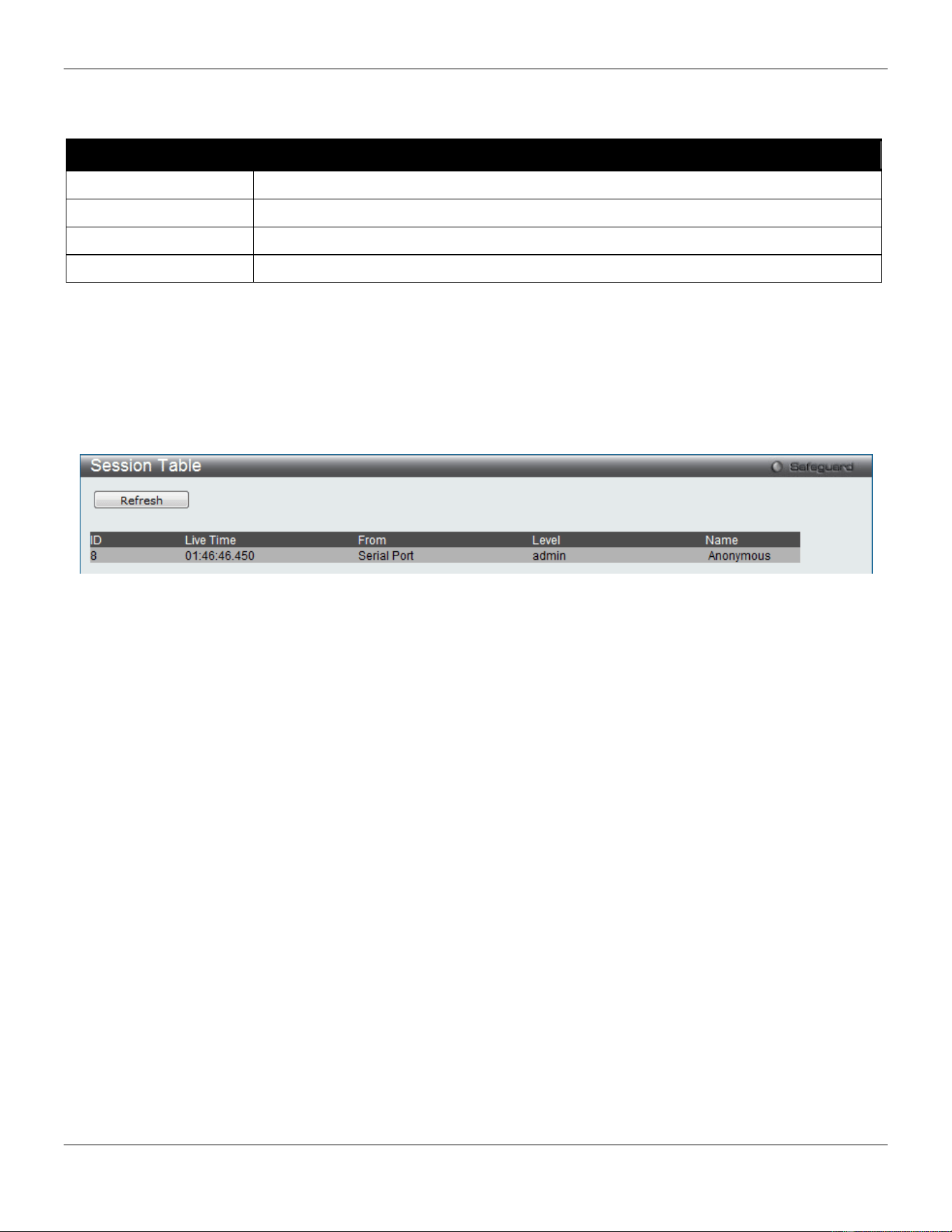
xStack® DGS-3420 Series Layer 2 Managed Stackable Gigabit Switch Web UI Reference Guide
52
Figure 3-17 Out of Band management Settings window
The fields that can be configured are described below:
Parameter Description
IP Address
Enter the IP address of the interface.
Subnet Mask
Enter the subnet mask of the IP address.
Gateway
Enter the gateway IP address of the out-of-band management network.
Status
Use the drop-down menu to enable or disable the interface status.
Click the Apply button to accept the changes made.
Session Table
Users can display the management sessions since the Switch was last rebooted.
To view the following window, click Management > Session Table, as show below:
Figure 3-18 Session Table window
Click the Refresh button to refresh the display table so that new entries will appear.
Single IP Management
Simply put, D-Link Single IP Management is a concept that will stack switches together over Ethernet instead of using
stacking ports or modules. There are some advantages in implementing the “Single IP Management” feature:
1. SIM can simplify management of small workgroups or wiring closets while scaling the network to handle
increased bandwidth demand.
2. SIM can reduce the number of IP address needed in your network.
3. SIM can eliminate any specialized cables for stacking connectivity and remove the distance barriers that
typically limit your topology options when using other stacking technology.
Switches using D-Link Single IP Management (labeled here as SIM) must conform to the following rules:
• SIM is an optional feature on the Switch and can easily be enabled or disabled through the Command Line
Interface or Web Interface. SIM grouping has no effect on the normal operation of the Switch in the user’s
network.
• There are three classifications for switches using SIM. The Commander Switch (CS), which is the master
switch of the group, Member Switch (MS), which is a switch that is recognized by the CS a member of a SIM
group, and a Candidate Switch (CaS), which is a Switch that has a physical link to the SIM group but has not
been recognized by the CS as a member of the SIM group.
• A SIM group can only have one Commander Switch (CS).
• A SIM group accepts up to 32 switches (numbered 1-32), not including the Commander Switch (numbered 0).
• Members of a SIM group cannot cross a router.
• There is no limit to the number of SIM groups in the same IP subnet (broadcast domain); however a single
switch can only belong to one group.

xStack® DGS-3420 Series Layer 2 Managed Stackable Gigabit Switch Web UI Reference Guide
53
• If multiple VLANs are configured, the SIM group will only utilize the default VLAN on any switch.
• SIM allows intermediate devices that do not support SIM. This enables the user to manage switches that are
more than one hop away from the CS.
The SIM group is a group of switches that are managed as a single entity. The Switch may take on three different roles:
1. Commander Switch (CS) – This is a switch that has been manually configured as the controlling device for a
group, and takes on the following characteristics:
a. It has an IP Address.
b. It is not a command switch or member switch of another Single IP group.
c. It is connected to the member switches through its management VLAN.
2. Member Switch (MS) – This is a switch that has joined a single IP group and is accessible from the CS, and it
takes on the following characteristics:
a. It is not a CS or MS of another IP group.
b. It is connected to the CS through the CS management VLAN.
3. Candidate Switch (CaS) – This is a switch that is ready to join a SIM group but is not yet a member of the SIM
group. The Candidate Switch may join the SIM group of the Switch by manually configuring it to be a MS of a
SIM group. A switch configured as a CaS is not a member of a SIM group and will take on the following
characteristics:
a. It is not a CS or MS of another Single IP group.
b. It is connected to the CS through the CS management VLAN
The following rules also apply to the above roles:
• Each device begins in a Candidate state.
• CSs must change their role to CaS and then to MS, to become a MS of a SIM group. Thus, the CS cannot
directly be converted to a MS.
• The user can manually configure a CS to become a CaS.
• A MS can become a CaS by:
o Being configured as a CaS through the CS.
o If report packets from the CS to the MS time out.
• The user can manually configure a CaS to become a CS
• The CaS can be configured through the CS to become a MS.
After configuring one switch to operate as the CS of a SIM group, additional DGS-3420 Series switches may join the
group by manually configuring the Switch to be a MS. The CS will then serve as the in band entry point for access to
the MS. The CS’s IP address will become the path to all MS’s of the group and the CS’s Administrator’s password,
and/or authentication will control access to all MS’s of the SIM group.
With SIM enabled, the applications in the CS will redirect the packet instead of executing the packets. The applications
will decode the packet from the administrator, modify some data, and then send it to the MS. After execution, the CS
may receive a response packet from the MS, which it will encode and send it back to the administrator.
When a CaS becomes a MS, it automatically becomes a member of the first SNMP community (includes read/write
and read only) to which the CS belongs. However, if a MS has its own IP address, it can belong to SNMP communities
to which itself belongs to.
Single IP Settings
The Switch is set as a Candidate (CaS) as the factory default configuration and Single IP Management is disabled.
To view the following window, click Management > Single IP Management > Single IP Settings, as show below:
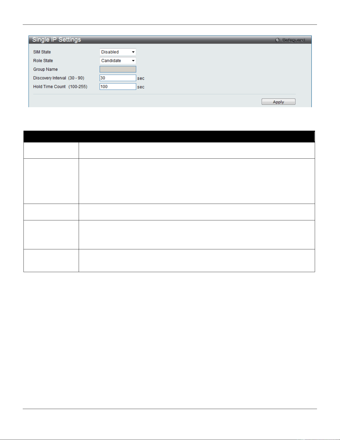
xStack® DGS-3420 Series Layer 2 Managed Stackable Gigabit Switch Web UI Reference Guide
54
Figure 3-19 Single IP Settings window
The fields that can be configured are described below:
Parameter Description
SIM State Use the drop-down menu to either enable or disable the SIM state on the Switch. Disabled
will render all SIM functions on the Switch inoperable.
Role State
Use the drop-down menu to change the SIM role of the Switch. The two choices are:
Candidate – A Candidate Switch (CaS) is not the member of a SIM group but is connected to
a Commander Switch. This is the default setting for the SIM role of the Switch.
Commander – Choosing this parameter will make the Switch a Commander Switch (CS). The
user may join other switches to this Switch, over Ethernet, to be part of its SIM group.
Choosing this option will also enable the Switch to be configured for SIM.
Group Name
Enter a Group Name in this textbox. This is optional. This name is used to segment switches
into different SIM groups.
Discovery Interval
(30-90)
The user may set the discovery protocol interval, in seconds that the Switch will send out
discovery packets. Returning information to a Commander Switch will include information
about other switches connected to it. (Ex. MS, CaS). The user may set the Discovery Interval
from 30 to 90 seconds. The default value is 30 seconds.
Hold Time Count
(100-255)
This parameter may be set for the time, in seconds; the Switch will hold information sent to it
from other switches, utilizing the Discovery Interval. The user may set the hold time from 100
to 255 seconds. The default value is 100 seconds.
Click the Apply button to accept the changes made.
After enabling the Switch to be a Commander Switch (CS), the Single IP Management folder will then contain four
added links to aid the user in configuring SIM through the web, including Topology, Firmware Upgrade,
Configuration Backup/Restore and Upload Log File.
Topology
This window will be used to configure and manage the Switch within the SIM group and requires Java script to function
properly on your computer.
The Java Runtime Environment on your server should initiate and lead you to the Topology window, as seen below.
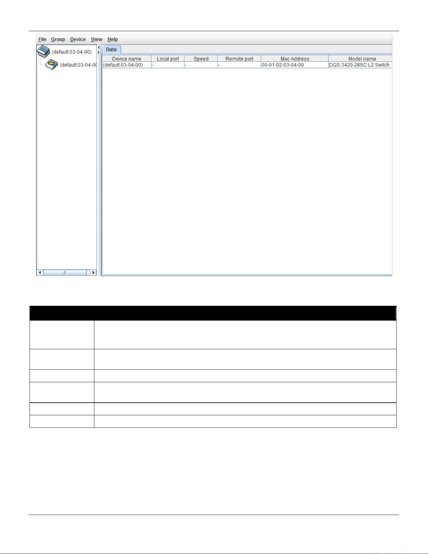
xStack® DGS-3420 Series Layer 2 Managed Stackable Gigabit Switch Web UI Reference Guide
55
Figure 3-20 Single IP Management window - Tree View
The Topology window holds the following information on the Data tab:
Parameter Description
Device Name
This field will display the Device Name of the switches in the SIM group configured by the user.
If no device is configured by the name, it will be given the name default and tagged with the
last six digits of the MAC Address to identify it.
Local Port
Displays the number of the physical port on the MS or CaS to which the CS is connected. The
CS will have no entry in this field.
Speed
Displays the connection speed between the CS and the MS or CaS.
Remote Port
Displays the number of the remote physical port by which the MS or CaS connect to CS. The
CS will have no entry in this field.
MAC Address
Displays the MAC Address of the corresponding Switch.
Model Name
Displays the full Model Name of the corresponding Switch.
To view the Topology View window, open the View drop-down menu in the toolbar and then click Topology, which will
open the following Topology Map. This window will refresh itself periodically (20 seconds by default).
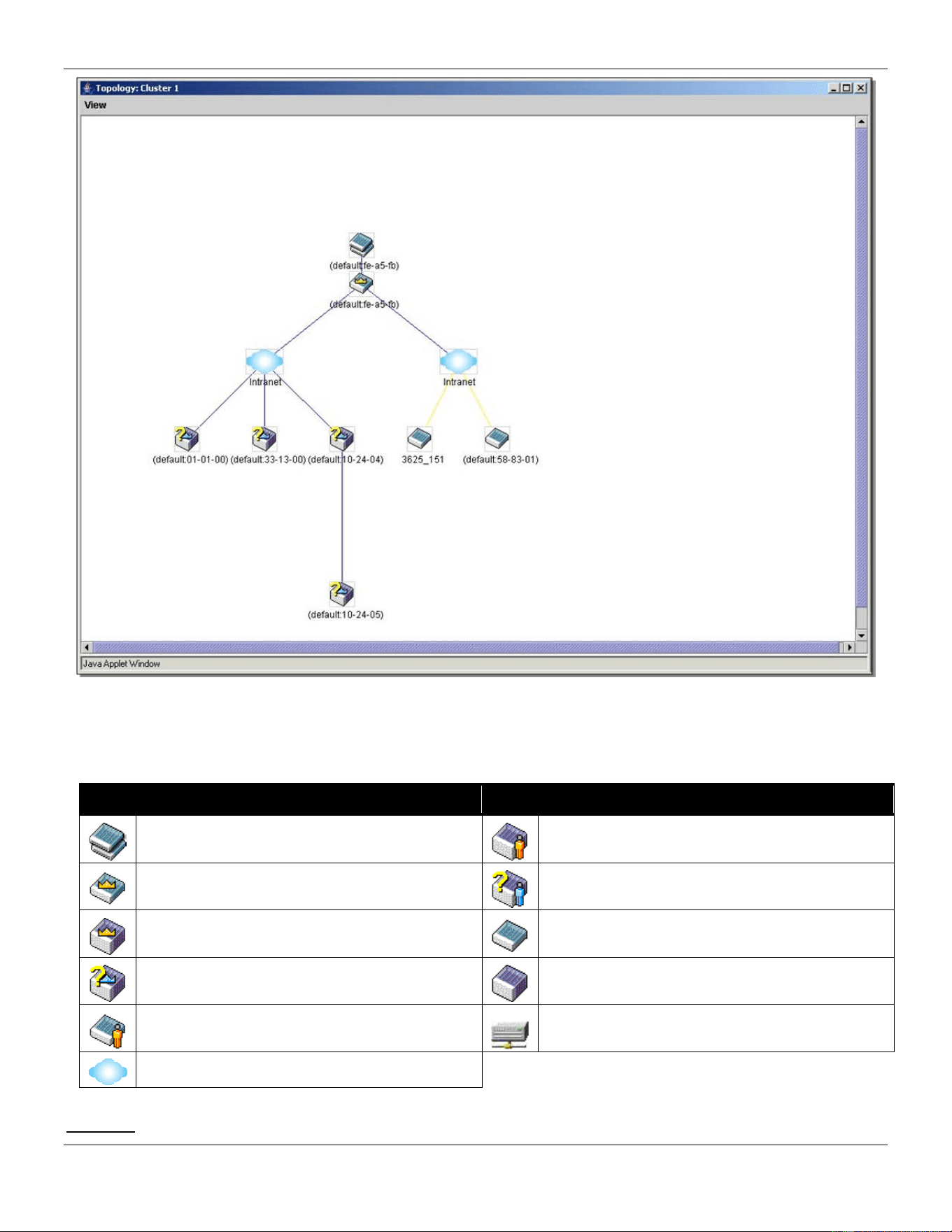
xStack® DGS-3420 Series Layer 2 Managed Stackable Gigabit Switch Web UI Reference Guide
56
Figure 3-21 Topology view
This window will display how the devices within the Single IP Management Group connect to other groups and devices.
Possible icons on this window are as follows:
Icon Description Icon Description
Group
Layer 3 member switch
Layer 2 commander switch
Member switch of other group
Layer 3 commander switch
Layer 2 candidate switch
Commander switch of other group
Layer 3 candidate switch
Layer 2 member switch.
Unknown device
Non-SIM devices
Tool Tips
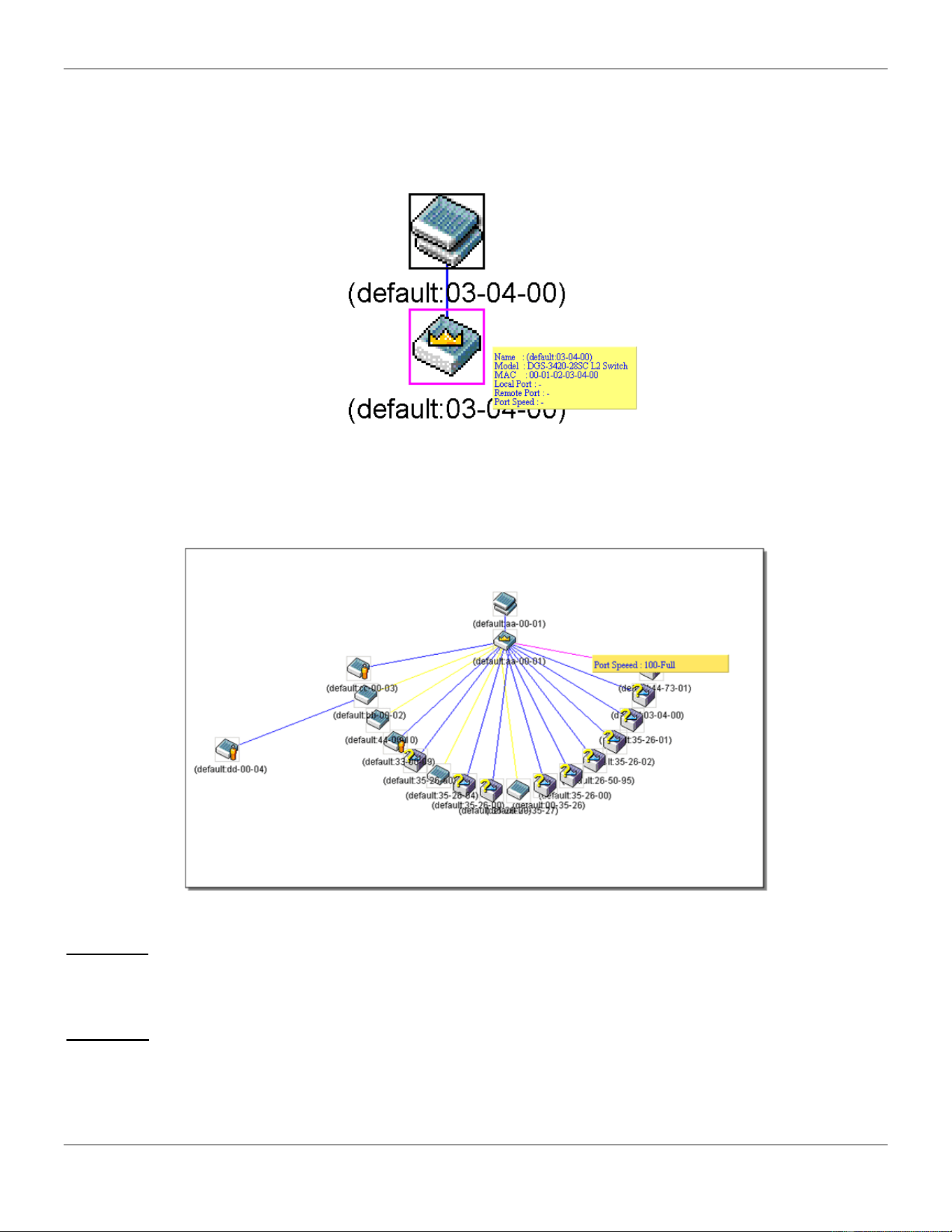
xStack® DGS-3420 Series Layer 2 Managed Stackable Gigabit Switch Web UI Reference Guide
57
In the Topology view window, the mouse plays an important role in configuration and in viewing device information.
Setting the mouse cursor over a specific device in the topology window (tool tip) will display the same information
about a specific device as the Tree view does. See the window below for an example.
Figure 3-22 Device Information Utilizing the Tool Tip
Setting the mouse cursor over a line between two devices will display the connection speed between the two devices,
as shown below.
Figure 3-23 Port Speed Utilizing the Tool Tip
Right-Click
Right-clicking on a device will allow the user to perform various functions, depending on the role of the Switch in the
SIM group and the icon associated with it.
Group Icon
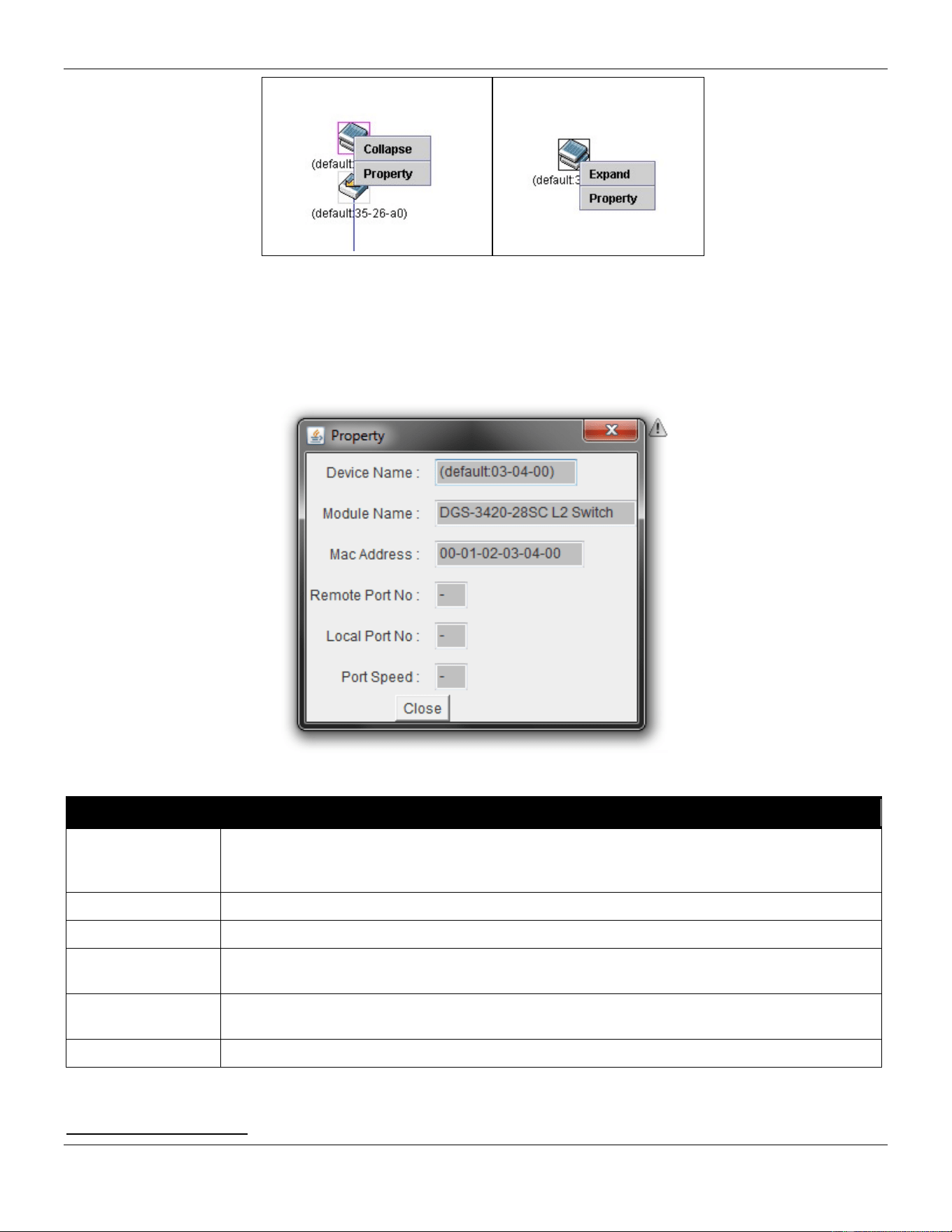
xStack® DGS-3420 Series Layer 2 Managed Stackable Gigabit Switch Web UI Reference Guide
58
Figure 3-24 Right-Clicking a Group Icon
The following options may appear for the user to configure:
• Collapse – To collapse the group that will be represented by a single icon.
• Expand – To expand the SIM group, in detail.
• Property – To pop up a window to display the group information.
Figure 3-25 Property window
Parameter Description
Device Name
This field will display the Device Name of the switches in the SIM group configured by the
user. If no Device Name is configured by the name, it will be given the name default and
tagged with the last six digits of the MAC Address to identify it.
Module Name
Displays the full module name of the switch that was right-clicked.
MAC Address
Displays the MAC Address of the corresponding Switch.
Remote Port No
Displays the number of the remote physical port by which the MS or CaS connect to CS. The
CS will have no entry in this field.
Local Port No
Displays the number of the physical port on the MS or CaS that the CS is connected to. The
CS will have no entry in this field.
Port Speed
Displays the connection speed between the CS and the MS or CaS
Click the Close button to close the property window.
Commander Switch Icon
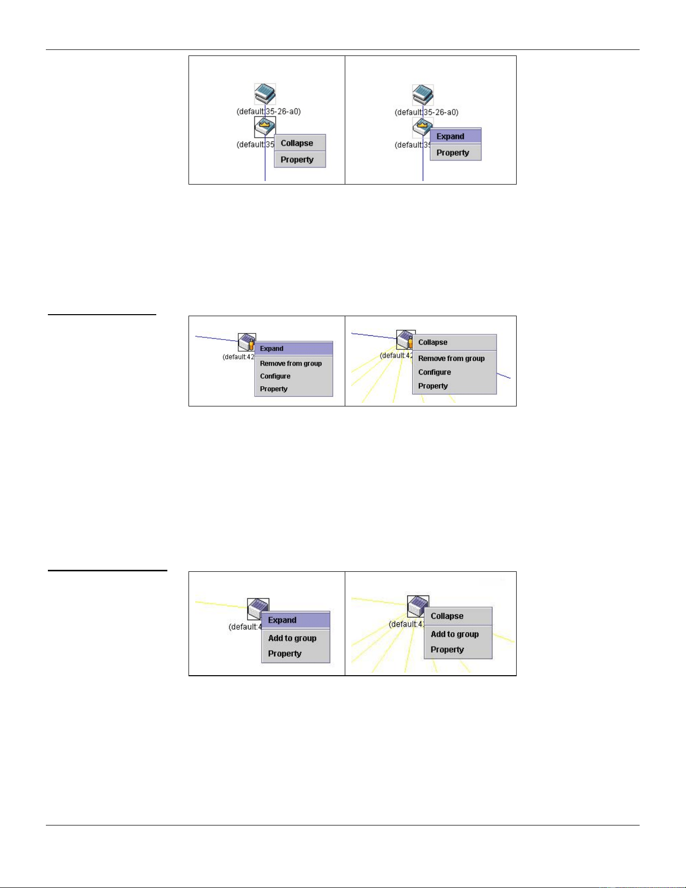
xStack® DGS-3420 Series Layer 2 Managed Stackable Gigabit Switch Web UI Reference Guide
59
Figure 3-26 Right-clicking a Commander Icon
The following options may appear for the user to configure:
• Collapse – To collapse the group that will be represented by a single icon.
• Expand – To expand the SIM group, in detail.
• Property – To pop up a window to display the group information.
Member Switch Icon
Figure 3-27 Right-clicking a Member icon
The following options may appear for the user to configure:
• Collapse – To collapse the group that will be represented by a single icon.
• Expand – To expand the SIM group, in detail.
• Remove from group – Remove a member from a group.
• Configure – Launch the web management to configure the Switch.
• Property – To pop up a window to display the device information.
Candidate Switch Icon
Figure 3-28 Right-clicking a Candidate icon
The following options may appear for the user to configure:
• Collapse – To collapse the group that will be represented by a single icon.
• Expand – To expand the SIM group, in detail.
• Add to group – Add a candidate to a group. Clicking this option will reveal the following dialog box for the
user to enter a password for authentication from the Candidate Switch before being added to the SIM group.
Click OK to enter the password or Cancel to exit the dialog box.
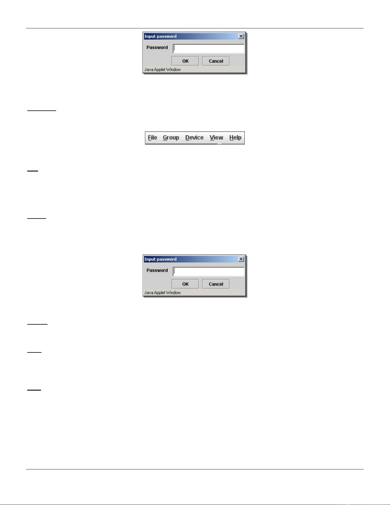
xStack® DGS-3420 Series Layer 2 Managed Stackable Gigabit Switch Web UI Reference Guide
60
Figure 3-29 Input password window
• Property – To pop up a window to display the device information.
Menu Bar
The Single IP Management window contains a menu bar for device configurations, as seen below.
Figure 3-30 Menu Bar of the Topology View
File
• Print Setup – Will view the image to be printed.
• Print Topology – Will print the topology map.
• Preference – Will set display properties, such as polling interval, and the views to open at SIM startup.
Group
• Add to group – Add a candidate to a group. Clicking this option will reveal the following dialog box for the
user to enter a password for authentication from the Candidate Switch before being added to the SIM group.
Click OK to enter the password or Cancel to exit the dialog box.
Figure 3-31 Input password window
• Remove from Group – Remove an MS from the group.
Device
• Configure – Will open the Web manager for the specific device.
View
• Refresh – Update the views with the latest status.
• Topology – Display the Topology view.
Help
• About – Will display the SIM information, including the current SIM version.
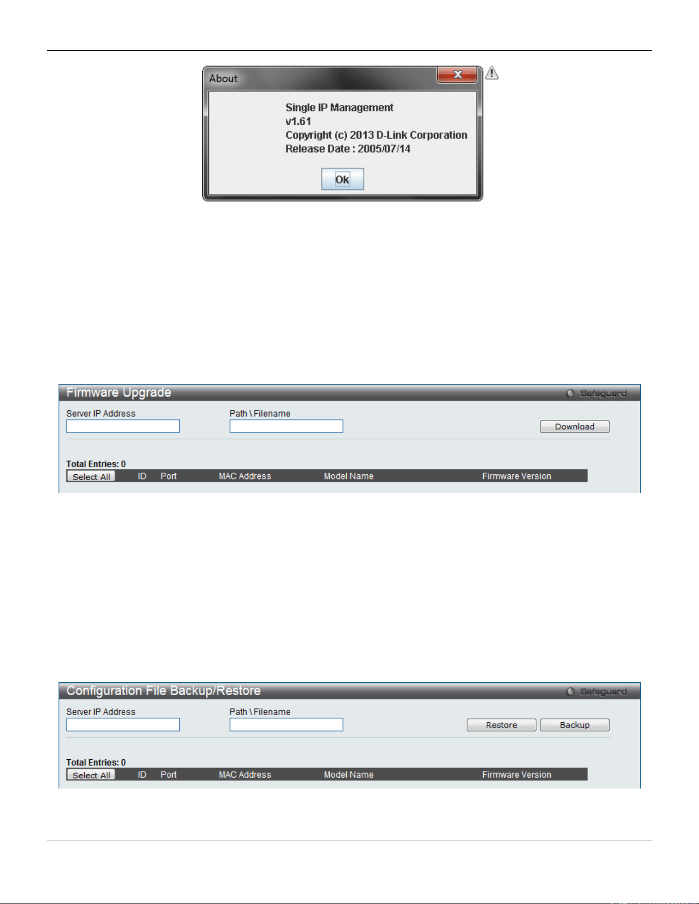
xStack® DGS-3420 Series Layer 2 Managed Stackable Gigabit Switch Web UI Reference Guide
61
Figure 3-32 About window
Firmware Upgrade
This screen is used to upgrade firmware from the Commander Switch to the Member Switch. Member Switches will be
listed in the table and will be specified by Port (port on the CS where the MS resides), MAC Address, Model Name
and Version. To specify a certain Switch for firmware download, click its corresponding check box under the Port
heading. To update the firmware, enter the Server IP Address where the firmware resides and enter the
Path/Filename of the firmware. Click Download to initiate the file transfer.
To view the following window, click Management > Single IP Management > Firmware Upgrade, as show below:
Figure 3-33 Firmware Upgrade window
Configuration File Backup/Restore
This screen is used to upgrade configuration files from the Commander Switch to the Member Switch using a TFTP
server. Member Switches will be listed in the table and will be specified by ID, Port (port on the CS where the MS
resides), MAC Address, Model Name and Firmware Version. To update the configuration file, enter the Server IP
Address where the file resides and enter the Path/Filename of the configuration file. Click Restore to initiate the file
transfer from a TFTP server to the Switch. Click Backup to backup the configuration file to a TFTP server.
To view the following window, click Management > Single IP Management > Configuration File Backup/Restore,
as show below:
Figure 3-34 Configuration File Backup/Restore window
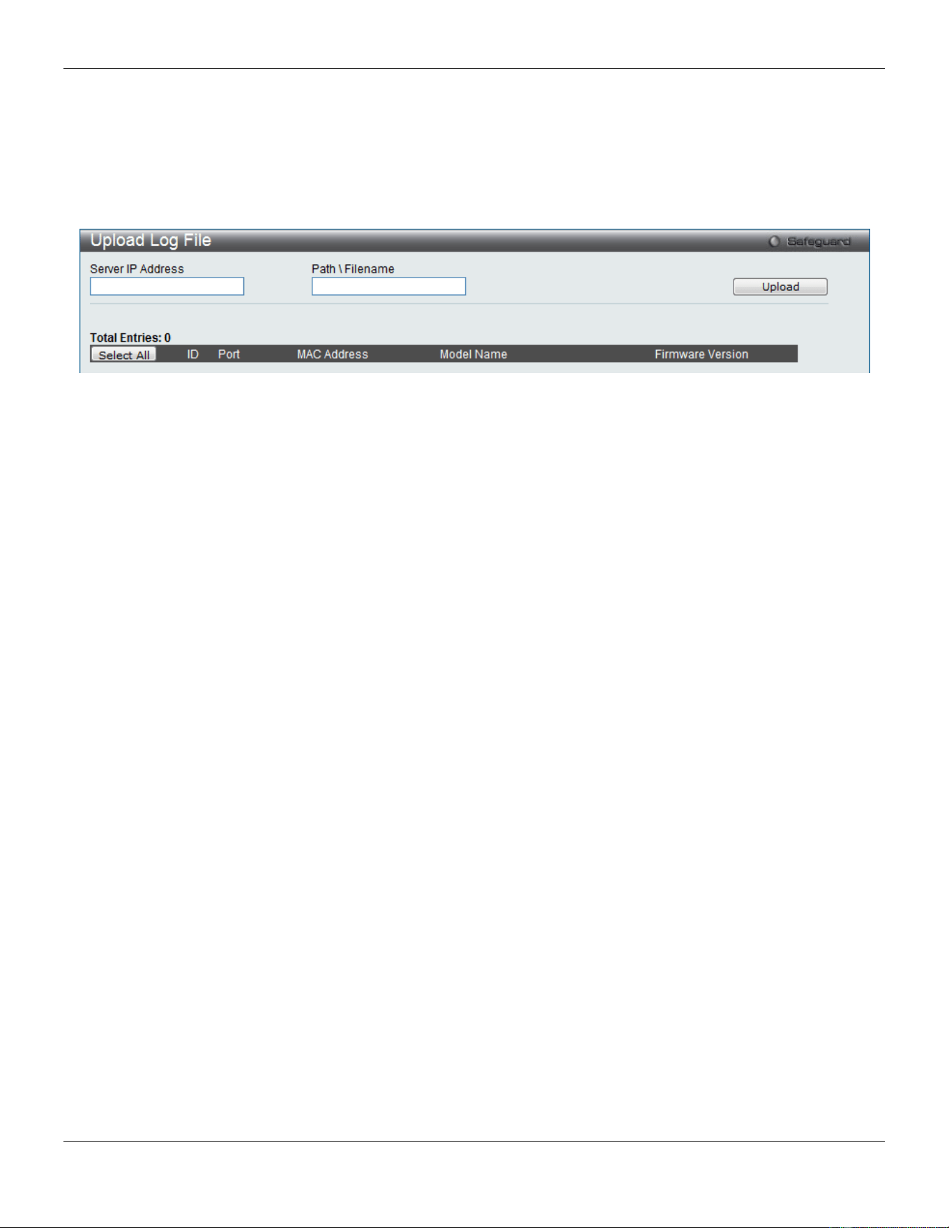
xStack® DGS-3420 Series Layer 2 Managed Stackable Gigabit Switch Web UI Reference Guide
62
Upload Log File
The following window is used to upload log files from SIM member switches to a specified PC. To upload a log file,
enter the Server IP address of the SIM member switch and then enter a Path\Filename on your PC where you wish to
save this file. Click Upload to initiate the file transfer.
To view the following window, click Management > Single IP Management > Upload Log File, as show below:
Figure 3-35 Upload Log File window
SNMP Settings
Simple Network Management Protocol (SNMP) is an OSI Layer 7 (Application Layer) designed specifically for
managing and monitoring network devices. SNMP enables network management stations to read and modify the
settings of gateways, routers, switches, and other network devices. Use SNMP to configure system features for proper
operation, monitor performance and detect potential problems in the Switch, switch group or network.
Managed devices that support SNMP include software (referred to as an agent), which runs locally on the device. A
defined set of variables (managed objects) is maintained by the SNMP agent and used to manage the device. These
objects are defined in a Management Information Base (MIB), which provides a standard presentation of the
information controlled by the on-board SNMP agent. SNMP defines both the format of the MIB specifications and the
protocol used to access this information over the network.
The Switch supports the SNMP versions 1, 2c, and 3. The three versions of SNMP vary in the level of security
provided between the management station and the network device.
In SNMP v.1 and v.2, user authentication is accomplished using ‘community strings’, which function like passwords.
The remote user SNMP application and the Switch SNMP must use the same community string. SNMP packets from
any station that has not been authenticated are ignored (dropped).
The default community strings for the Switch used for SNMP v.1 and v.2 management access are:
• public – Allows authorized management stations to retrieve MIB objects.
• private – Allows authorized management stations to retrieve and modify MIB objects.
SNMPv3 uses a more sophisticated authentication process that is separated into two parts. The first part is to maintain
a list of users and their attributes that are allowed to act as SNMP managers. The second part describes what each
user on that list can do as an SNMP manager.
The Switch allows groups of users to be listed and configured with a shared set of privileges. The SNMP version may
also be set for a listed group of SNMP managers. Thus, you may create a group of SNMP managers that are allowed
to view read-only information or receive traps using SNMPv1 while assigning a higher level of security to another group,
granting read/write privileges using SNMPv3.
Using SNMPv3 individual users or groups of SNMP managers can be allowed to perform or be restricted from
performing specific SNMP management functions. The functions allowed or restricted are defined using the Object
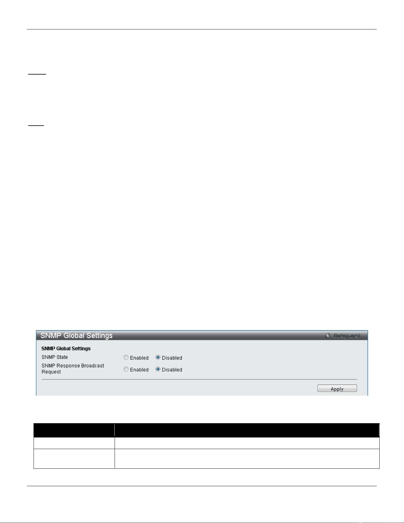
xStack® DGS-3420 Series Layer 2 Managed Stackable Gigabit Switch Web UI Reference Guide
63
Identifier (OID) associated with a specific MIB. An additional layer of security is available for SNMPv3 in that SNMP
messages may be encrypted. To read more about how to configure SNMPv3 settings for the Switch read the next
section.
Traps
Traps are messages that alert network personnel of events that occur on the Switch. The events can be as serious as
a reboot (someone accidentally turned OFF the Switch), or less serious like a port status change. The Switch
generates traps and sends them to the trap recipient (or network manager). Typical traps include trap messages for
Authentication Failure, Topology Change and Broadcast\Multicast Storm.
MIBs
The Switch in the Management Information Base (MIB) stores management and counter information. The Switch uses
the standard MIB-II Management Information Base module. Consequently, values for MIB objects can be retrieved
from any SNMP-based network management software. In addition to the standard MIB-II, the Switch also supports its
own proprietary enterprise MIB as an extended Management Information Base. Specifying the MIB Object Identifier
may also retrieve the proprietary MIB. MIB values can be either read-only or read-write.
The Switch incorporates a flexible SNMP management for the switching environment. SNMP management can be
customized to suit the needs of the networks and the preferences of the network administrator. Use the SNMP V3
menus to select the SNMP version used for specific tasks.
The Switch supports the Simple Network Management Protocol (SNMP) versions 1, 2c, and 3. The administrator can
specify the SNMP version used to monitor and control the Switch. The three versions of SNMP vary in the level of
security provided between the management station and the network device.
SNMP settings are configured using the menus located on the SNMP V3 folder of the Web manager. Workstations on
the network that are allowed SNMP privileged access to the Switch can be restricted with the Management Station IP
Address menu.
SNMP Global Settings
SNMP global state settings can be enabled or disabled.
To view the following window, click Management > SNMP Settings > SNMP Global Settings, as show below:
Figure 3-36 SNMP Global Settings window
The fields that can be configured are described below:
Parameter Description
SNMP State
Select to enable or disable SNMP feature.
SNMP Response
Broadcast Request
Select to enable or disable the SNMP response broadcast request option.
Click the Apply button to accept the changes made.
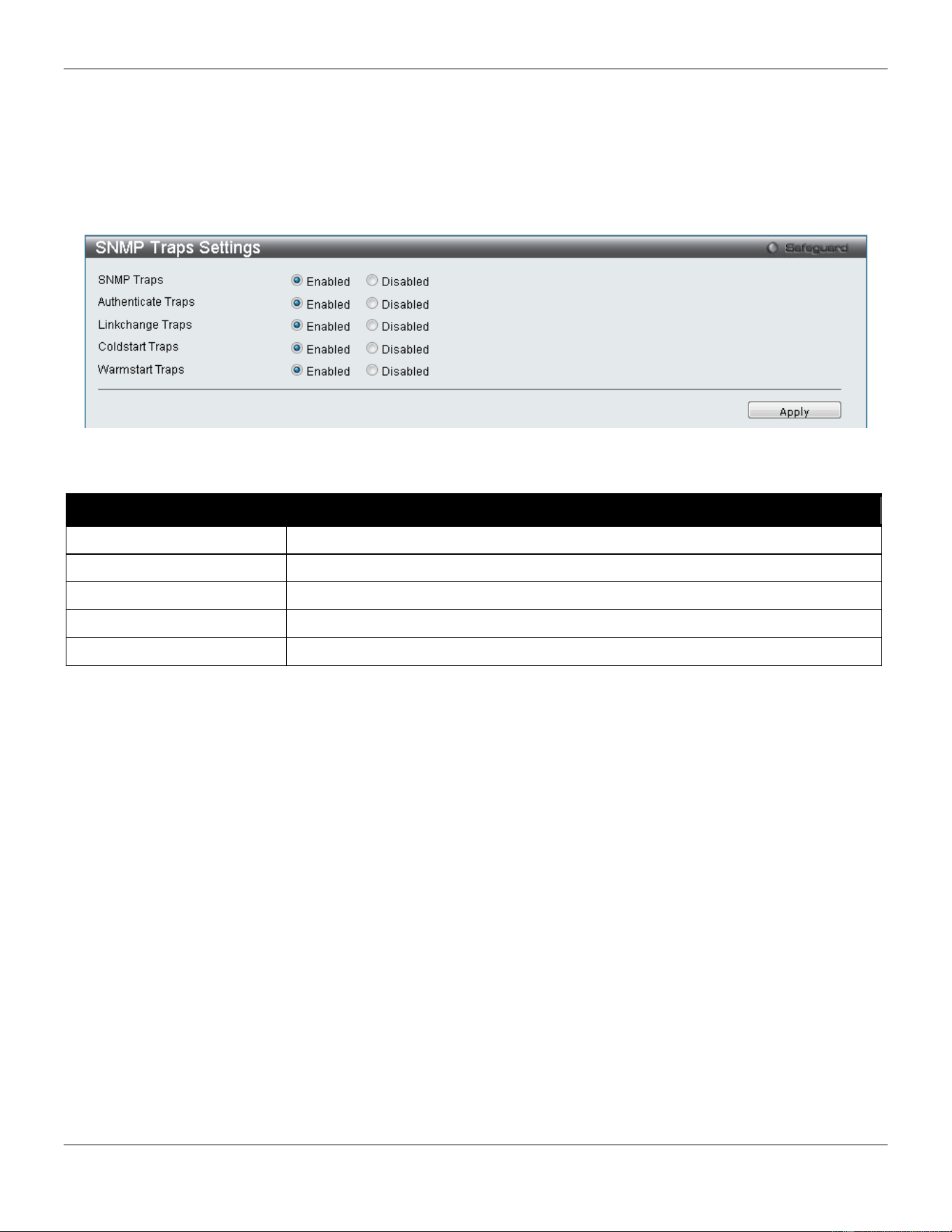
xStack® DGS-3420 Series Layer 2 Managed Stackable Gigabit Switch Web UI Reference Guide
64
SNMP Traps Settings
Users can enable and disable the SNMP trap support function of the switch and SNMP authentication failure trap
support, respectively.
To view the following window, click Management > SNMP Settings > SNMP Traps Settings, as show below:
Figure 3-37 SNMP Traps Settings window
The fields that can be configured are described below:
Parameter Description
SNMP Traps
Enable this option to use the SNMP Traps feature.
Authentication Traps
Enable this option to use the SNMP Authentication Traps feature.
Linkchange Traps
Enable this option to use the SNMP Link Change Traps feature.
Coldstart Traps
Enable this option to use the SNMP Cold Start Traps feature.
Warmstart Traps
Enable this option to use the SNMP Warm Start Traps feature.
Click the Apply button to accept the changes made.
SNMP Linkchange Traps Settings
On this page the user can configure the SNMP link change trap settings.
To view the following window, click Management > SNMP Settings > SNMP Linkchange Traps Settings, as show
below:
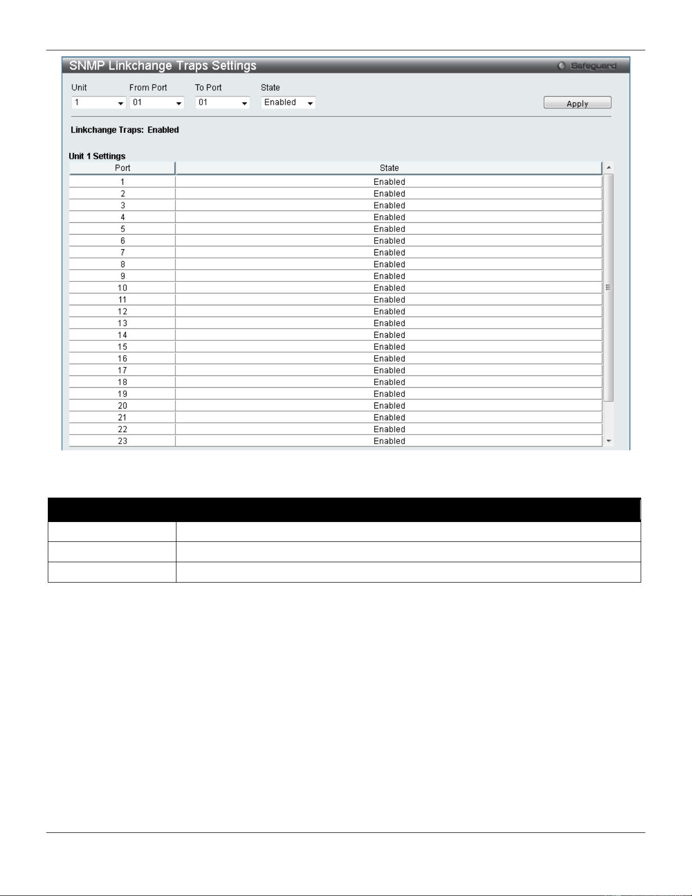
xStack® DGS-3420 Series Layer 2 Managed Stackable Gigabit Switch Web UI Reference Guide
65
Figure 3-38 SNMP Linkchange Traps Settings window
The fields that can be configured are described below:
Parameter Description
Unit
Select the unit you wish to configure.
From Port / To Port
Select the starting and ending ports to use.
State
Use the drop-down menu to enable or disable the SNMP link change Trap.
Click the Apply button to accept the changes made.
SNMP View Table Settings
Users can assign views to community strings that define which MIB objects can be accessed by a remote SNMP
manager. The SNMP Group created with this table maps SNMP users (identified in the SNMP User Table) to the views
created in the previous window.
To view the following window, click Management > SNMP Settings > SNMP View Table Settings, as show below:
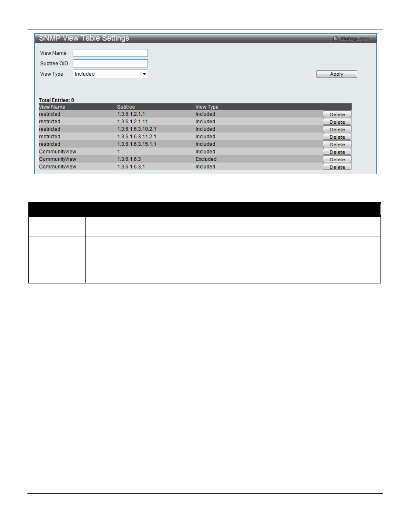
xStack® DGS-3420 Series Layer 2 Managed Stackable Gigabit Switch Web UI Reference Guide
66
Figure 3-39 SNMP View Table Settings window
The fields that can be configured are described below:
Parameter Description
View Name
Type an alphanumeric string of up to 32 characters. This is used to identify the new SNMP view
being created.
Subtree OID
Type the Object Identifier (OID) Subtree for the view. The OID identifies an object tree (MIB tree)
that will be included or excluded from access by an SNMP manager.
View Type
Select Included to include this object in the list of objects that an SNMP manager can access.
Select Excluded to exclude this object from the list of objects that an SNMP manager can
access.
Click the Apply button to accept the changes made.
Click the Delete button to remove the specific entry.
SNMP Community Table Settings
Users can create an SNMP community string to define the relationship between the SNMP manager and an agent. The
community string acts like a password to permit access to the agent on the Switch. One or more of the following
characteristics can be associated with the community string:
• An Access List of IP addresses of SNMP managers that are permitted to use the community string to gain
access to the Switch’s SNMP agent.
• Any MIB view that defines the subset of all MIB objects will be accessible to the SNMP community.
• Read/write or read-only level permission for the MIB objects accessible to the SNMP community.
To view the following window, click Management > SNMP Settings > SNMP Community Table Settings, as show
below:
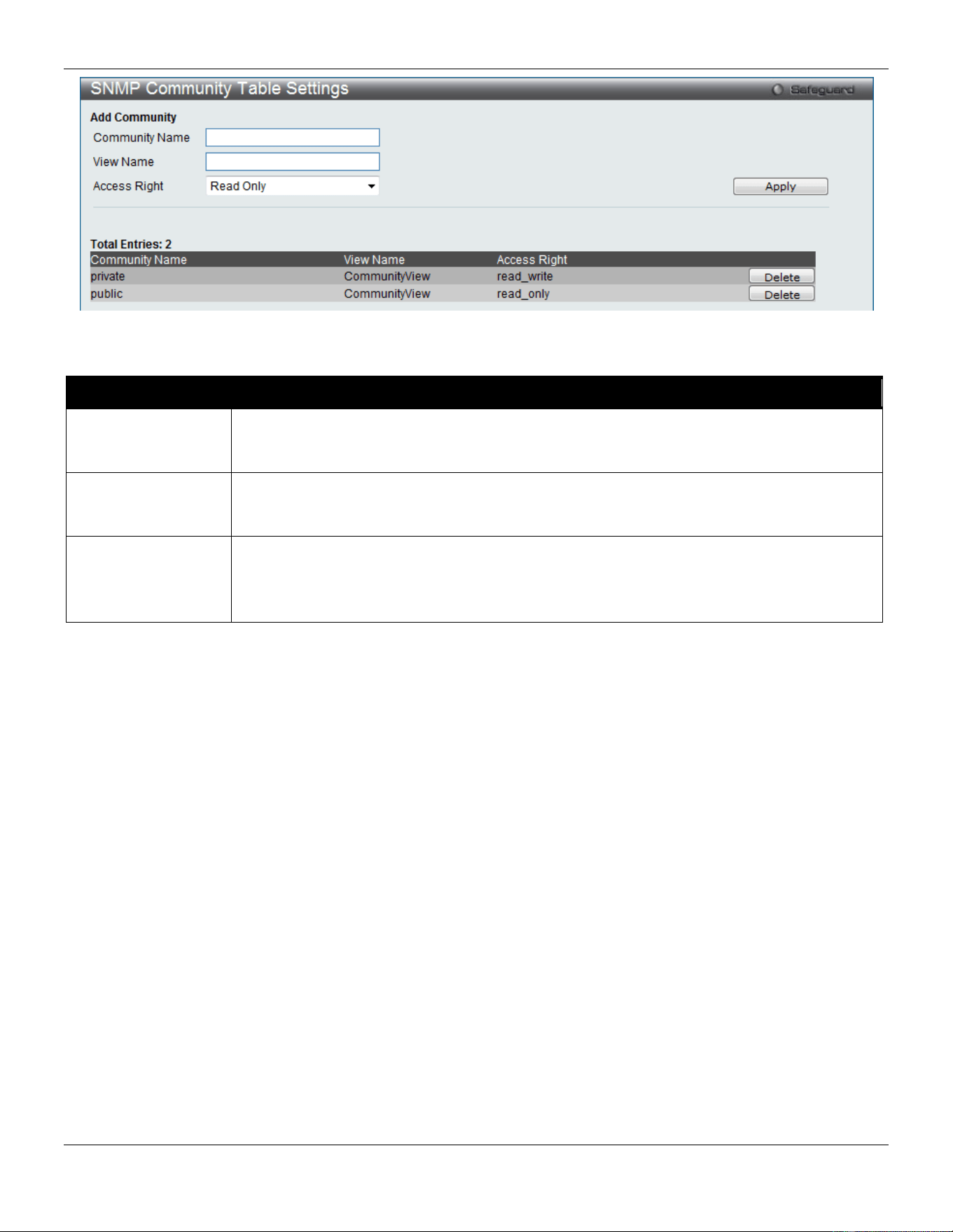
xStack® DGS-3420 Series Layer 2 Managed Stackable Gigabit Switch Web UI Reference Guide
67
Figure 3-40 SNMP community Table Settings window
The fields that can be configured are described below:
Parameter Description
Community Name
Type an alphanumeric string of up to 32 characters that is used to identify members of an
SNMP community. This string is used like a password to give remote SNMP managers
access to MIB objects in the Switch’s SNMP agent.
View Name
Type an alphanumeric string of up to 32 characters that is used to identify the group of MIB
objects that a remote SNMP manager is allowed to access on the Switch. The view name
must exist in the SNMP View Table.
Access Right Read Only – Specify that SNMP community members using the community string created
can only read the contents of the MIBs on the Switch.
Read Write – Specify that SNMP community members using the community string created
can read from, and write to the contents of the MIBs on the Switch.
Click the Apply button to accept the changes made.
Click the Delete button to remove the specific entry.
SNMP Group Table Settings
An SNMP Group created with this table maps SNMP users (identified in the SNMP User Table) to the views created in
the previous window.
To view the following window, click Management > SNMP Settings > SNMP Group Table Settings, as show below:
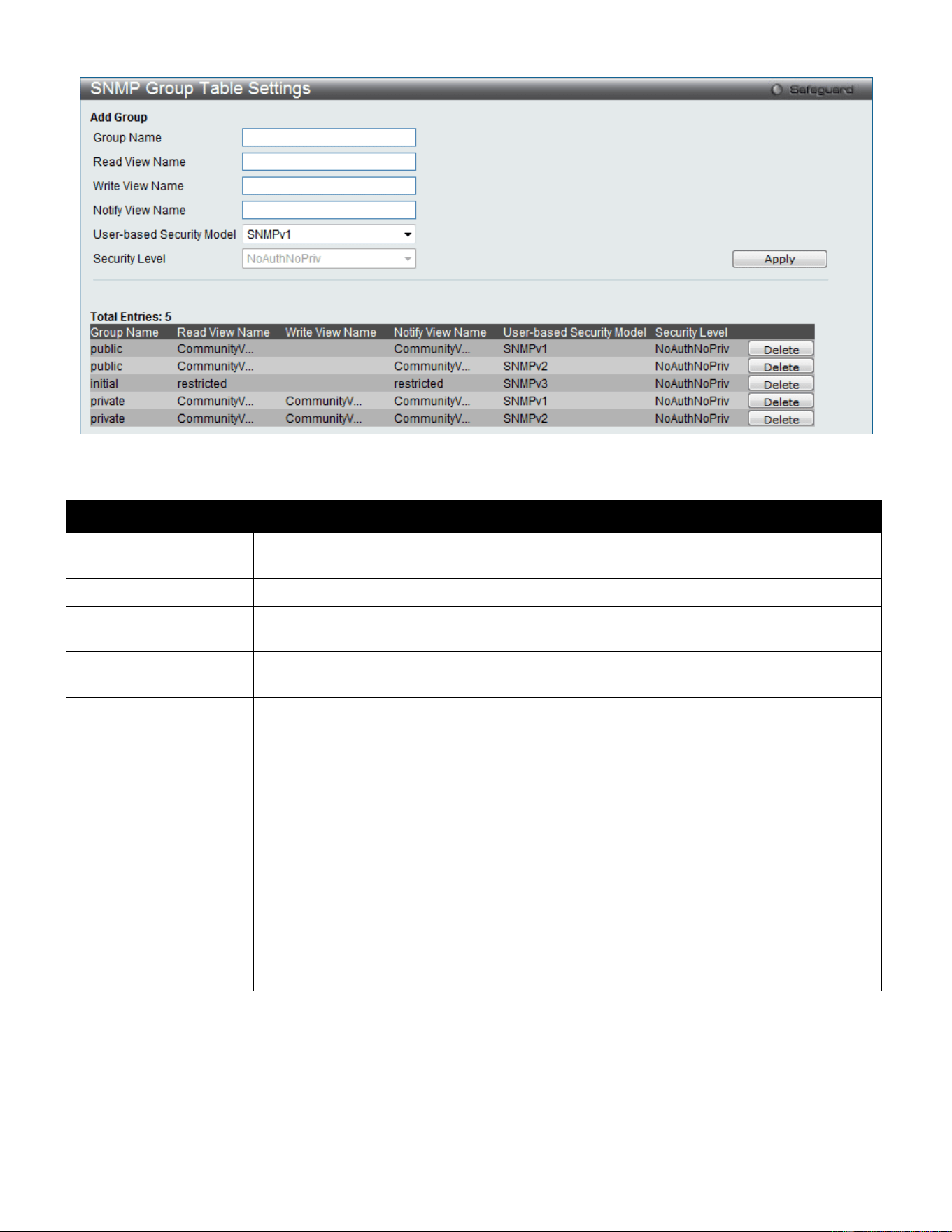
xStack® DGS-3420 Series Layer 2 Managed Stackable Gigabit Switch Web UI Reference Guide
68
Figure 3-41 SNMP Group Table Settings window
The fields that can be configured are described below:
Parameter Description
Group Name
Type an alphanumeric string of up to 32 characters. This is used to identify the new
SNMP group of SNMP users.
Read View Name
This name is used to specify the SNMP group created can request SNMP messages.
Write View Name
Specify a SNMP group name for users that are allowed SNMP write privileges to the
Switch’s SNMP agent.
Notify View Name
Specify a SNMP group name for users that can receive SNMP trap messages generated
by the Switch’s SNMP agent.
User-based Security
Model
SNMPv1 – Specify that SNMP version 1 will be used.
SNMPv2 – Specify that SNMP version 2c will be used. The SNMPv2 supports both
centralized and distributed network management strategies. It includes improvements in
the Structure of Management Information (SMI) and adds some security features.
SNMPv3 – Specify that the SNMP version 3 will be used. SNMPv3 provides secure
access to devices through a combination of authentication and encrypting packets over
the network.
Security Level
The Security Level settings only apply to SNMPv3.
NoAuthNoPriv – Specify that there will be no authorization and no encryption of packets
sent between the Switch and a remote SNMP manager.
AuthNoPriv – Specify that authorization will be required, but there will be no encryption
of packets sent between the Switch and a remote SNMP manager.
AuthPriv – Specify that authorization will be required, and that packets sent between the
Switch and a remote SNMP manger will be encrypted.
Click the Apply button to accept the changes made.
Click the Delete button to remove the specific entry.
SNMP Engine ID Settings
The Engine ID is a unique identifier used for SNMP V3 implementations on the Switch.
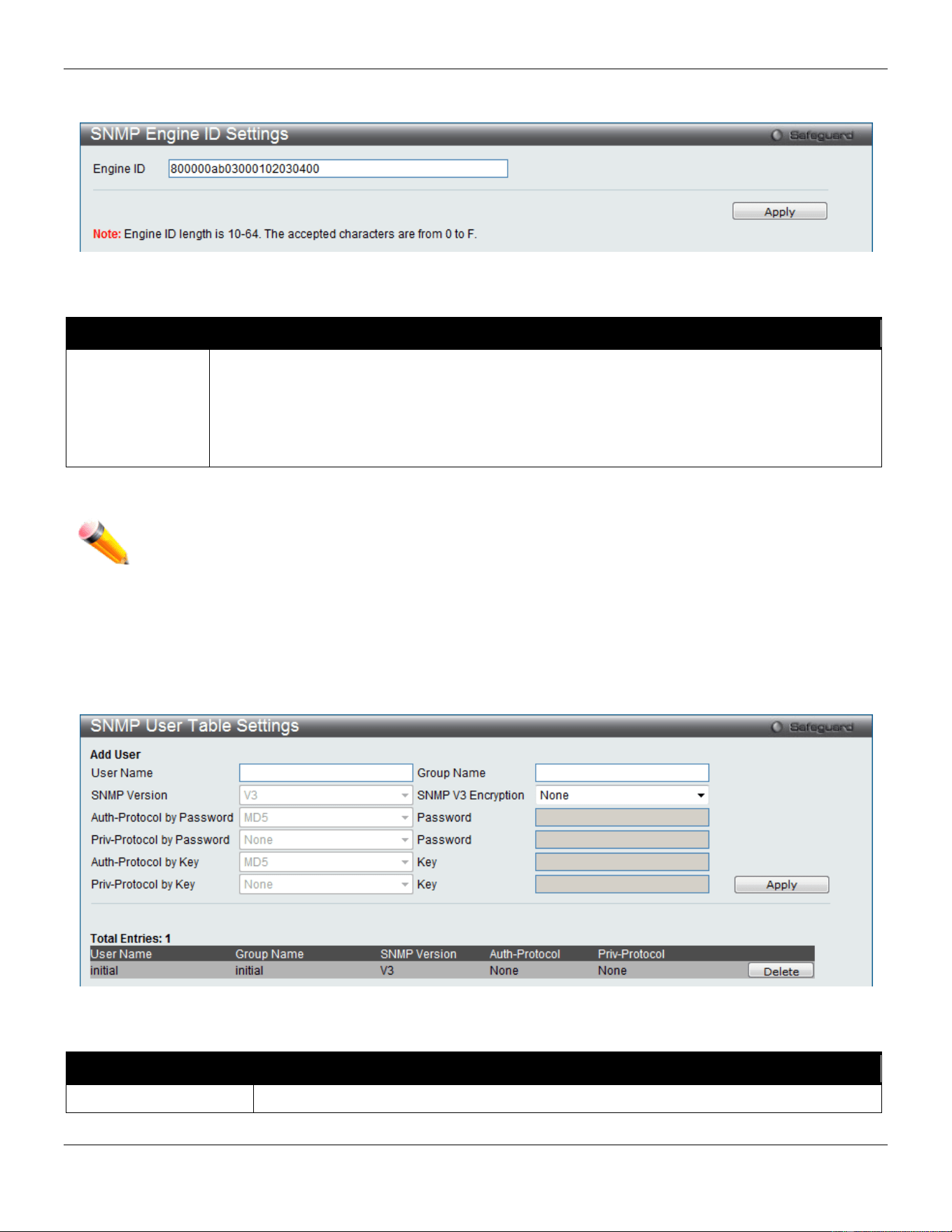
xStack® DGS-3420 Series Layer 2 Managed Stackable Gigabit Switch Web UI Reference Guide
69
To view the following window, click Management > SNMP Settings > SNMP Engine ID Settings, as show below:
Figure 3-42 SNMP Engine ID Settings window
The fields that can be configured are described below:
Parameter Description
Engine ID
To change the Engine ID, type the new Engine ID value in the space provided. The SNMP
engine ID displays the identification of the SNMP engine on the Switch. The default value is
suggested in RFC2271. The very first bit is 1, and the first four octets are set to the binary
equivalent of the agent’s SNMP management private enterprise number as assigned by IANA
(D-Link is 171). The fifth octet is 03 to indicate the rest is the MAC address of this device. The
sixth to eleventh octets is the MAC address.
Click the Apply button to accept the changes made.
NOTE: The Engine ID length is 10-64 and accepted characters can range from 0 to F.
SNMP User Table Settings
This window displays all of the SNMP User’s currently configured on the Switch.
To view the following window, click Management > SNMP Settings > SNMP User Table Settings, as show below:
Figure 3-43 SNMP User Table Settings window
The fields that can be configured are described below:
Parameter Description
User Name
An alphanumeric string of up to 32 characters. This is used to identify the SNMP users.
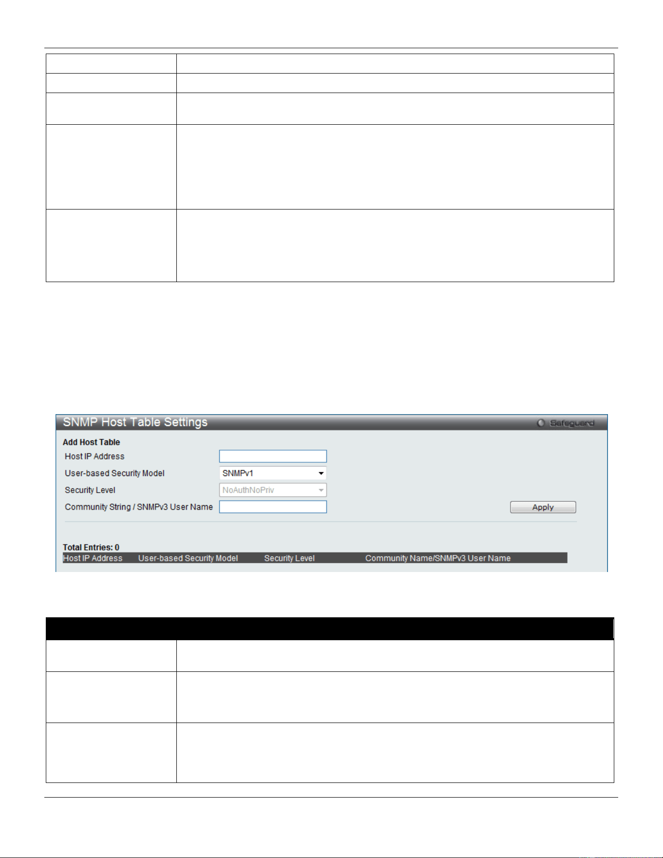
xStack® DGS-3420 Series Layer 2 Managed Stackable Gigabit Switch Web UI Reference Guide
70
Group Name
This name is used to specify the SNMP group created can request SNMP messages.
SNMP Version
V3 – Indicates that SNMP version 3 is in use.
SNMP V3 Encryption
Use the drop-down menu to enable encryption for SNMP V3. This is only operable in
SNMP V3 mode. The choices are None, Password, or Key.
Auth-Protocol MD5 – Specify that the HMAC-MD5-96 authentication level will be used. This field is only
operable when V3 is selected in the SNMP Version field and the Encryption field has
been checked. This field will require the user to enter a password.
SHA – Specify that the HMAC-SHA authentication protocol will be used. This field is only
operable when V3 is selected in the SNMP Version field and the Encryption field has
been checked. This field will require the user to enter a password.
Priv-Protocol None – Specify that no authorization protocol is in use.
DES – Specify that DES 56-bit encryption is in use, based on the CBC-DES (DES-56)
standard. This field is only operable when V3 is selected in the SNMP Version field and
the Encryption field has been checked. This field will require the user to enter a
password.
Click the Apply button to accept the changes made.
Click the Delete button to remove the specific entry.
SNMP Host Table Settings
Users can set up SNMP trap recipients for IPv4.
To view the following window, click Management > SNMP Settings > SNMP Host Table Settings, as show below:
Figure 3-44 SNMP Host Table Settings window
The fields that can be configured are described below:
Parameter Description
Host IP Address
Type the IP address of the remote management station that will serve as the SNMP host
for the Switch.
User-based Security
Model
SNMPv1 – Specify that SNMP version 1 will be used.
SNMPv2 – Specify that SNMP version 2 will be used.
SNMPv3 – Specify that SNMP version 3 will be used.
Security Level NoAuthNoPriv – To specify that the SNMP version 3 will be used, with a NoAuth-NoPriv
security level.
AuthNoPriv – To specify that the SNMP version 3 will be used, with an Auth-NoPriv
security level.
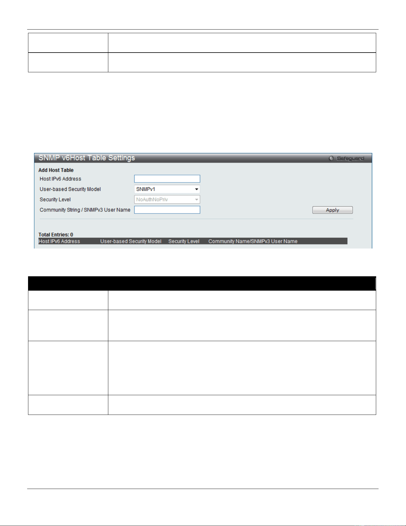
xStack® DGS-3420 Series Layer 2 Managed Stackable Gigabit Switch Web UI Reference Guide
71
AuthPriv – To specify that the SNMP version 3 will be used, with an Auth-Priv security
level.
Community String /
SNMPv3 User Name
Type in the community string or SNMP V3 user name as appropriate.
Click the Apply button to accept the changes made.
Click the Delete button to remove the specific entry.
SNMP v6Host Table Settings
Users can set up SNMP trap recipients for IPv6.
To view the following window, click Management > SNMP Settings > SNMP v6Host Table Settings, as show below:
3-45 SNMPv6 Host Table Settings
The fields that can be configured are described below:
Parameter Description
Host IPv6 Address
Type the IPv6 address of the remote management station that will serve as the SNMP
host for the Switch.
User-based Security
Model
SNMPv1 – Specifies that SNMP version 1 will be used.
SNMPv2 – Specifies that SNMP version 2 will be used.
SNMPv3 – Specifies that SNMP version 3 will be used.
Security Level NoAuthNoPriv – To specify that the SNMP version 3 will be used, with a NoAuth-NoPriv
security level.
AuthNoPriv – To specify that the SNMP version 3 will be used, with an Auth-NoPriv
security level.
AuthPriv – To specify that the SNMP version 3 will be used, with an Auth-Priv security
level.
Community String /
SNMPv3 User Name
Type in the community string or SNMP V3 user name as appropriate.
Click the Apply button to accept the changes made.
Click the Delete button to remove the specific entry.
RMON Settings
This window is used to enable or disable remote monitoring (RMON) for the rising and falling alarm trap feature for the
SNMP function on the Switch.
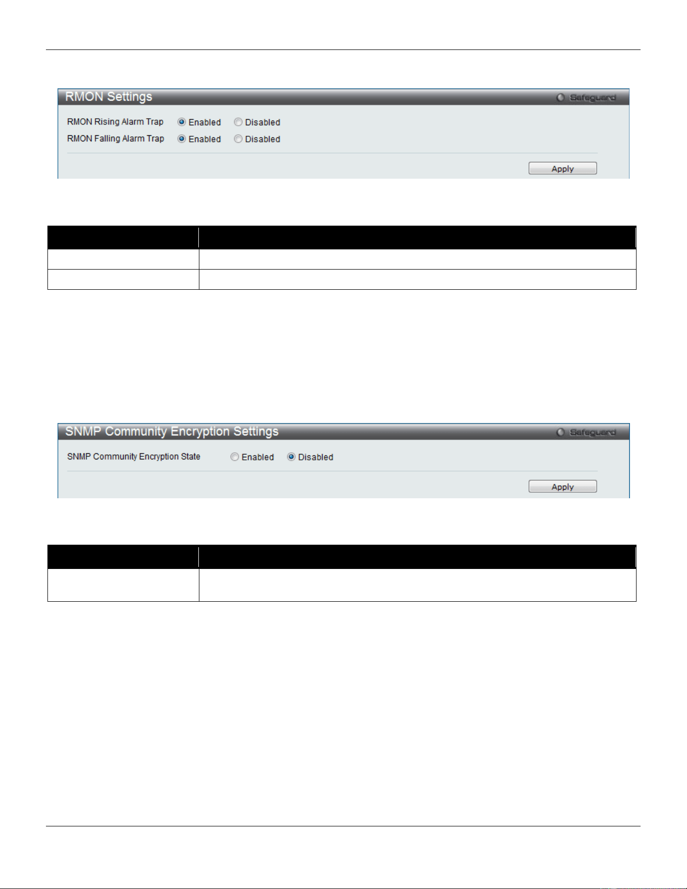
xStack® DGS-3420 Series Layer 2 Managed Stackable Gigabit Switch Web UI Reference Guide
72
To view the following window, click Management > SNMP Settings > RMON Settings, as show below:
Figure 3-46 RMON Settings window
The fields that can be configured are described below:
Parameter Description
RMON Rising Alarm Trap
Enable this option to use the RMON Rising Alarm Trap Feature.
RMON Falling Alarm Trap
Enable this option to use the RMON Falling Alarm Trap Feature.
Click the Apply button to accept the changes made.
SNMP Community Encryption Settings
This window is used to enable or disable the encryption state on the SNMP community string.
To view the following window, click Management > SNMP Settings > SNMP Community Encryption Settings, as
show below:
Figure 3-47 SNMP Community Encryption Settings window
The fields that can be configured are described below:
Parameter Description
SNMP Community
Encryption State
Click the Enabled or Disabled radio button to enable or disable the encryption.
Click the Apply button to accept the changes made.
SNMP Community Masking Settings
This window is used to choose a security method for creating an SNMP community string, but the community string
encrypted or not depends on the SNMP community encryption state.
To view the following window, click Management > SNMP Settings > SNMP Community Masking Settings, as show
below:
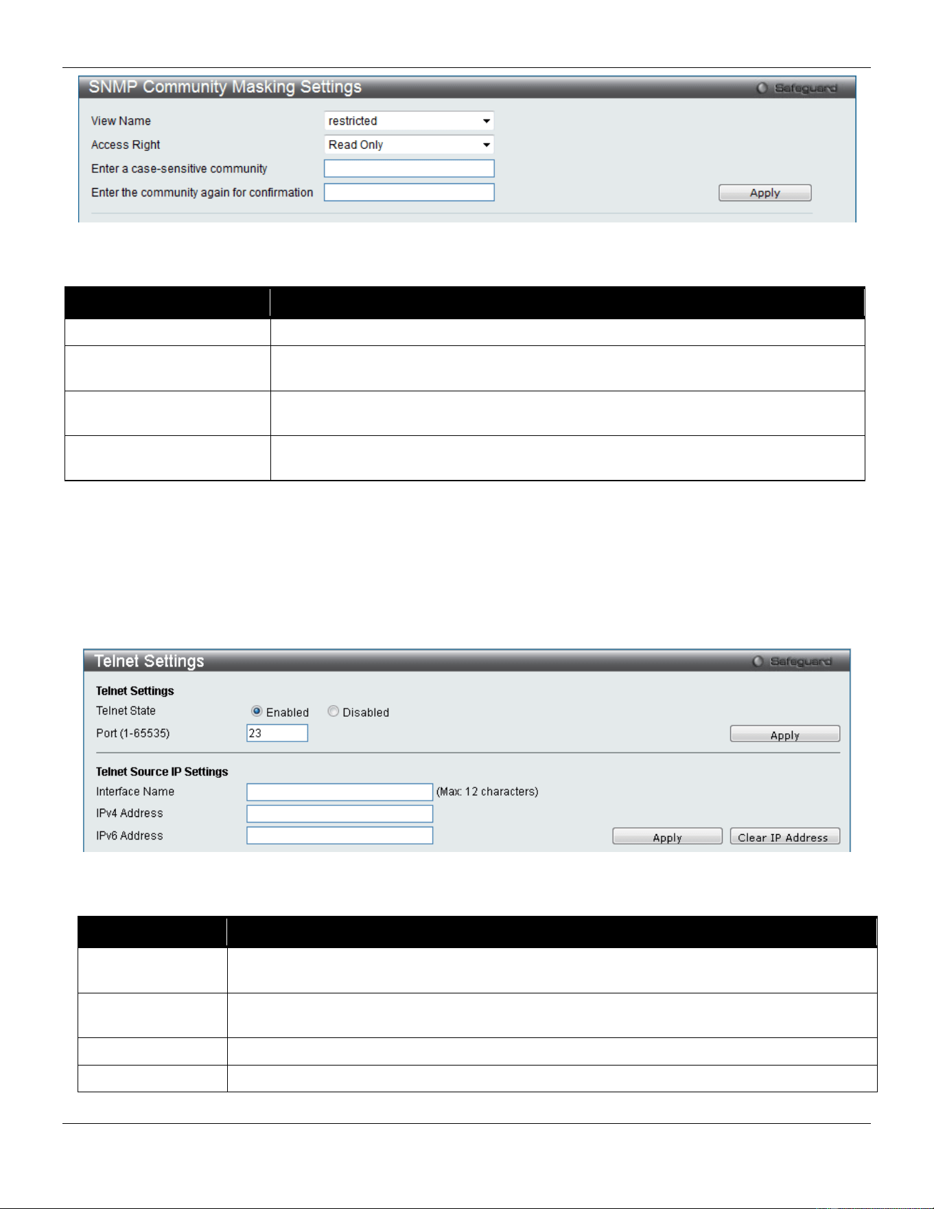
xStack® DGS-3420 Series Layer 2 Managed Stackable Gigabit Switch Web UI Reference Guide
73
Figure 3-48 SNMP community Maskking Settings window
The fields that can be configured are described below:
Parameter Description
View Name
Use the drop-down menu to choose the MIB view name.
Access right
Use the drop-down menu to select the access right for the user using the community
string. Available options are Read Only and Read Write.
Enter a case-sensitive
community
Enter a case-sensitive community string.
Enter the community
again for confirmation
Retype the community string for confirmation.
Click the Apply button to accept the changes made.
Telnet Settings
Users can configure Telnet Settings on the Switch.
To view the following window, click Management > Telnet Settings, as show below:
Figure 3-49 Telnet Settings window
The fields that can be configured are described below:
Parameter Description
Telnet State
Telnet configuration is Enabled by default. If you do not want to allow configuration of the
system through Telnet choose Disabled.
Port (1-65535)
The TCP port number used for Telnet management of the Switch. The “well-known” TCP port
for the Telnet protocol is 23.
Interface Name
Enter the TELNET source IP interface name used here.
IPv4 Address
Enter the TELNET source IPv4 address used here.
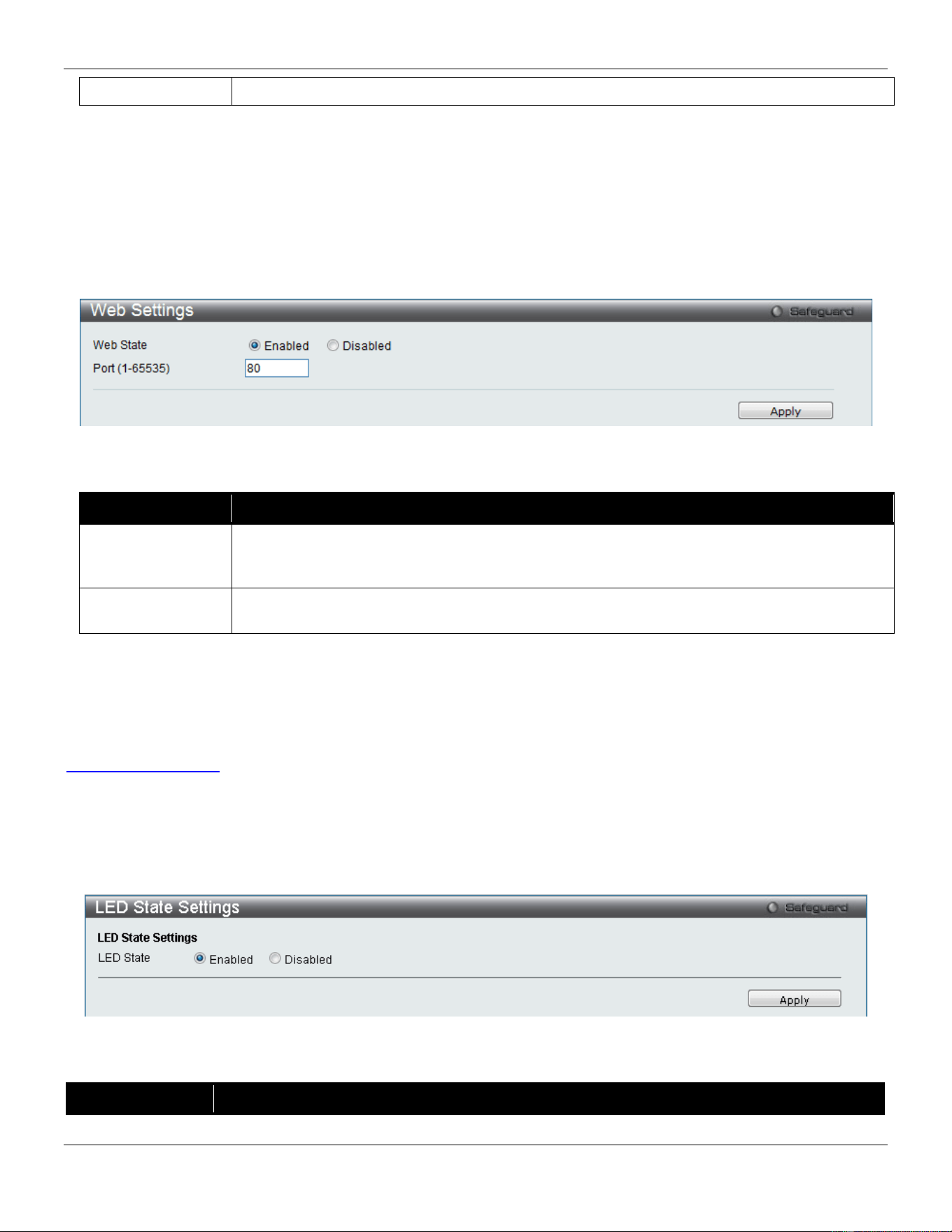
xStack® DGS-3420 Series Layer 2 Managed Stackable Gigabit Switch Web UI Reference Guide
74
IPv6 Address
Enter the TELNET source IPv6 address used here.
Click the Apply button to accept the changes made.
Click the Clear IP Address button to clear the IP addresses entered.
Web Settings
Users can configure the Web settings on the Switch.
To view the following window, click Management > Web Settings, as show below:
Figure 3-50 Web Settings window
The fields that can be configured are described below:
Parameter Description
Web Status
Web-based management is Enabled by default. If you choose to disable this by clicking
Disabled, you will lose the ability to configure the system through the web interface as soon
as these settings are applied.
Port (1-65535)
The TCP port number used for web-based management of the Switch. The “well-known” TCP
port for the Web protocol is 80.
Click the Apply button to accept the changes made.
Power Saving
Power Saving is one part of D-Link Green Technologies. To learn more about the D-Link Green Technologies, go to
http://green.dlink.com/
for more details.
LED State Settings
This window is used to configure the port LED state.
To view the following window, click Management > Power Saving > LED State Settings, as show below:
Figure 3-51 LED State Settings window
The fields that can be configured are described below:
Parameter Description
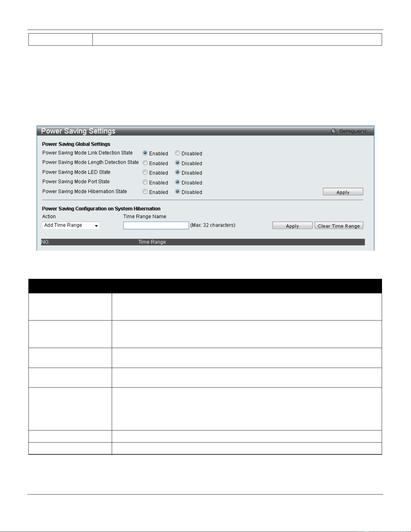
xStack® DGS-3420 Series Layer 2 Managed Stackable Gigabit Switch Web UI Reference Guide
75
LED State
Click the radio buttons to enable or disable the port LED state.
Click the Apply button to accept the changes made.
Power Saving Settings
This window allows the user to implement the Switch’s built-in power saving features and set the schedule to enforce
the settings.
To view the following window, click Management > Power Saving > Power Saving Settings, as show below:
Figure 3-52 Power Saving Settings window
The fields that can be configured are described below:
Parameter Description
Power Saving Mode
Link Detection State
Click the radio buttons to enable or disable the link detection state. When enabled, a
port which has a link down status will be turned off to save power to the Switch. This will
not affect the port’s capabilities when the port status is link up.
Power Saving Mode
Length Detection State
Click the radio buttons to enable or disable length detection state. When enabled, the
Switch will automatically determine the length of the cable and adjust the power flow
accordingly.
Power Saving Mode
LED State
Click the radio buttons to enable or disable LED state. When enabled, the LED’s state of
ports will be turned off during the configured time range.
Power Saving Mode
Port State
Click the radio buttons to enable or disable port state. When enabled, the ports will be
shut down during the configured time range.
Power Saving Mode
Hibernation State
Click the radio buttons to enable or disable hibernation state. When enabled, the Switch
will go into a low power state and be idle during the configured time range. It will shut
down all the ports, all network function (telnet, ping, etc.) will not work, and only the
console connection will work via the RS232 port. If the Switch is an endpoint type PSE
(Power Sourcing Equipment), it will not provide power to the port.
Action
Use the drop down menu to add or delete the schedule.
Time Range Name
Specify the name of the schedule.
Click the Apply button to accept the changes made for each individual section.
Click the Clear Time Range to remove all the entries.
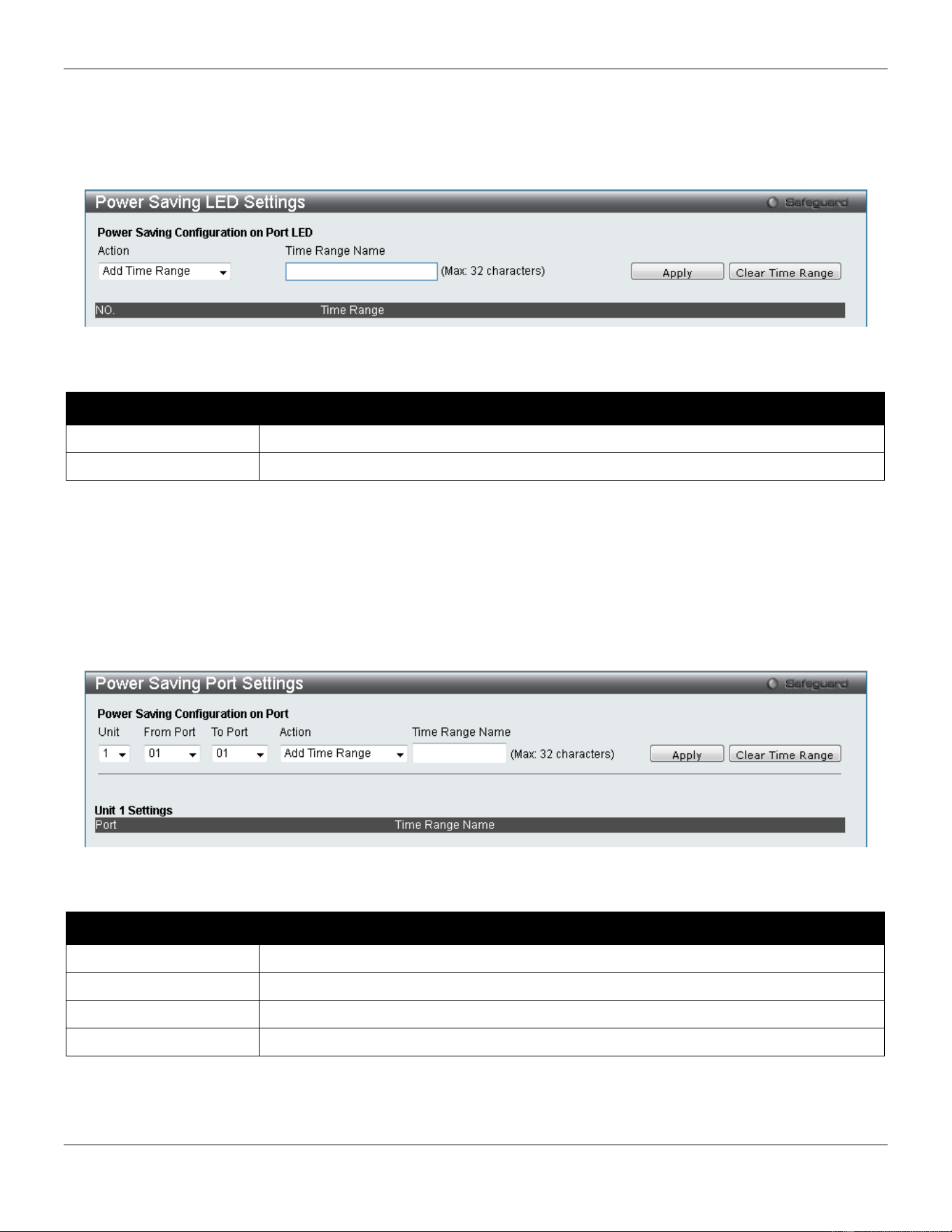
xStack® DGS-3420 Series Layer 2 Managed Stackable Gigabit Switch Web UI Reference Guide
76
Power Saving LED Settings
This window is used to add or delete the power saving schedule on the LED of all ports.
To view the following window, click Management > Power Saving > Power Saving LED Settings, as show below:
Figure 3-53 Power Saving LED Settings window
The fields that can be configured are described below:
Parameter Description
Action
Use the drop down menu to add or delete the schedule.
Time Range Name
Specify the name of the schedule.
Click the Apply button to accept the changes made for each individual section.
Click the Clear Time Range to remove all the entries.
Power Saving Port Settings
This window is used to set the power saving state.
To view the following window, click Management > Power Saving > Power Saving Port Settings, as show below:
Figure 3-54 Power Saving Port Settings
The fields that can be configured are described below:
Parameter Description
Unit
Select the unit you wish to configure.
From Port / To Port
Select the appropriate port range used for the configuration.
Action
Use the drop down menu to add or delete the schedule.
Time Range Name
Specify the name of the schedule.
Click the Apply button to accept the changes made for each individual section.
Click the Clear Time Range to remove all the entries.


xStack® DGS-3420 Series Layer 2 Managed Stackable Gigabit Switch Web UI Reference Guide
78
Chapter 4 L2 Features
VLAN
QinQ
Layer 2 Protocol Tunneling Settings
Spanning Tree
Link Aggregation
FDB
L2 Multicast Control
Multicast Filtering
ERPS Settings
LLDP
NLB FDB Settings
PTP
VLAN
Understanding IEEE 802.1p Priority
Priority tagging is a function defined by the IEEE 802.1p standard designed to provide a means of managing traffic on
a network where many different types of data may be transmitted simultaneously. It is intended to alleviate problems
associated with the delivery of time critical data over congested networks. The quality of applications that are
dependent on such time critical data, such as video conferencing, can be severely and adversely affected by even very
small delays in transmission.
Network devices that are in compliance with the IEEE 802.1p standard have the ability to recognize the priority level of
data packets. These devices can also assign a priority label or tag to packets. Compliant devices can also strip priority
tags from packets. This priority tag determines the packet’s degree of expeditiousness and determines the queue to
which it will be assigned.
Priority tags are given values from 0 to 7 with 0 being assigned to the lowest priority data and 7 assigned to the highest.
The highest priority tag 7 is generally only used for data associated with video or audio applications, which are
sensitive to even slight delays, or for data from specified end users whose data transmissions warrant special
consideration.
The Switch allows you to further tailor how priority tagged data packets are handled on your network. Using queues to
manage priority tagged data allows you to specify its relative priority to suit the needs of your network. There may be
circumstances where it would be advantageous to group two or more differently tagged packets into the same queue.
Generally, however, it is recommended that the highest priority queue, Queue 7, be reserved for data packets with a
priority value of 7. Packets that have not been given any priority value are placed in Queue 0 and thus given the lowest
priority for delivery.
Strict mode and weighted round robin system are employed on the Switch to determine the rate at which the queues
are emptied of packets. The ratio used for clearing the queues is 4:1. This means that the highest priority queue,
Queue 7, will clear 4 packets for every 1 packet cleared from Queue 0.
Remember, the priority queue settings on the Switch are for all ports, and all devices connected to the Switch will be
affected. This priority queuing system will be especially beneficial if your network employs switches with the capability
of assigning priority tags.

xStack® DGS-3420 Series Layer 2 Managed Stackable Gigabit Switch Web UI Reference Guide
79
VLAN Description
A Virtual Local Area Network (VLAN) is a network topology configured according to a logical scheme rather than the
physical layout. VLANs can be used to combine any collection of LAN segments into an autonomous user group that
appears as a single LAN. VLANs also logically segment the network into different broadcast domains so that packets
are forwarded only between ports within the VLAN. Typically, a VLAN corresponds to a particular subnet, although not
necessarily.
VLANs can enhance performance by conserving bandwidth, and improve security by limiting traffic to specific domains.
A VLAN is a collection of end nodes grouped by logic instead of physical location. End nodes that frequently
communicate with each other are assigned to the same VLAN, regardless of where they are physically on the network.
Logically, a VLAN can be equated to a broadcast domain, because broadcast packets are forwarded to only members
of the VLAN on which the broadcast was initiated.
Notes about VLANs on the Switch
• No matter what basis is used to uniquely identify end nodes and assign these nodes VLAN membership,
packets cannot cross VLANs without a network device performing a routing function between the VLANs.
• The Switch supports IEEE 802.1Q VLANs. The port untagging function can be used to remove the 802.1Q tag
from packet headers to maintain compatibility with devices that are tag-unaware.
• The Switch’s default is to assign all ports to a single 802.1Q VLAN named “default.”
• The “default” VLAN has a VID = 1.
• The member ports of Port-based VLANs may overlap, if desired.
IEEE 802.1Q VLANs
Some relevant terms:
• Tagging – The act of putting 802.1Q VLAN information into the header of a packet.
• Untagging – The act of stripping 802.1Q VLAN information out of the packet header.
• Ingress port – A port on a switch where packets are flowing into the Switch and VLAN decisions must be
made.
• Egress port – A port on a switch where packets are flowing out of the Switch, either to another switch or to an
end station, and tagging decisions must be made.
IEEE 802.1Q (tagged) VLANs are implemented on the Switch. 802.1Q VLANs require tagging, which enables them to
span the entire network (assuming all switches on the network are IEEE 802.1Q-compliant).
VLANs allow a network to be segmented in order to reduce the size of broadcast domains. All packets entering a
VLAN will only be forwarded to the stations (over IEEE 802.1Q enabled switches) that are members of that VLAN, and
this includes broadcast, multicast and unicast packets from unknown sources.
VLANs can also provide a level of security to your network. IEEE 802.1Q VLANs will only deliver packets between
stations that are members of the VLAN.
Any port can be configured as either tagging or untagging. The untagging feature of IEEE 802.1Q VLANs allows
VLANs to work with legacy switches that don’t recognize VLAN tags in packet headers. The tagging feature allows
VLANs to span multiple 802.1Q-compliant switches through a single physical connection and allows Spanning Tree to
be enabled on all ports and work normally.
The IEEE 802.1Q standard restricts the forwarding of untagged packets to the VLAN the receiving port is a member of.
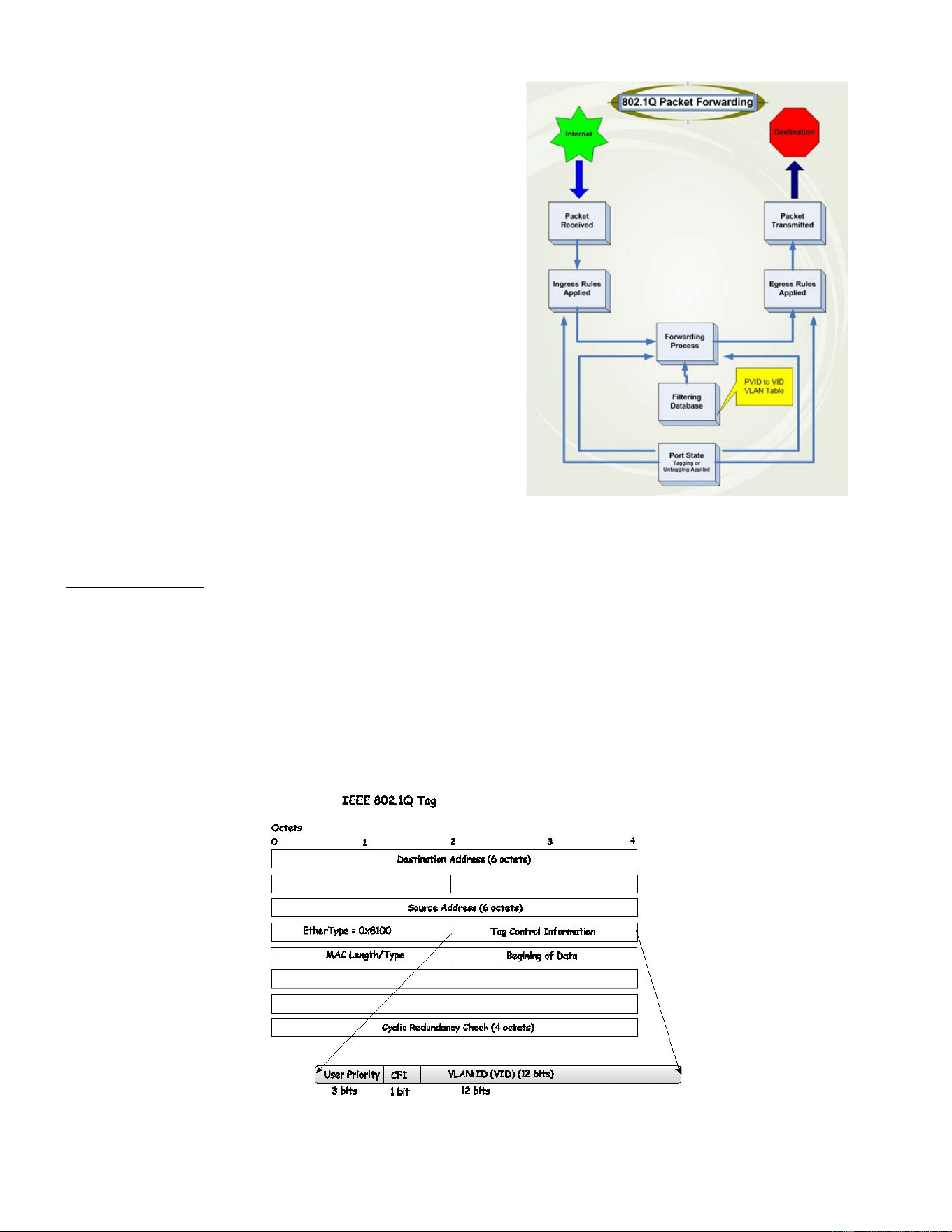
xStack® DGS-3420 Series Layer 2 Managed Stackable Gigabit Switch Web UI Reference Guide
80
The main characteristics of IEEE 802.1Q are as follows:
• Assigns packets to VLANs by filtering.
• Assumes the presence of a single global spanning
tree.
• Uses an explicit tagging scheme with one-level
tagging.
• 802.1Q VLAN Packet Forwarding
• Packet forwarding decisions are made based upon
the following three types of rules:
o Ingress rules – rules relevant to the
classification of received frames belonging to a
VLAN.
o Forwarding rules between ports – decides
whether to filter or forward the packet.
o Egress rules – determines if the packet must
be sent tagged or untagged.
Figure 4-1 IEEE 802.1Q Packet Forwarding
802.1Q VLAN Tags
The figure below shows the 802.1Q VLAN tag. There are four additional octets inserted after the source MAC address.
Their presence is indicated by a value of 0x8100 in the EtherType field. When a packet’s EtherType field is equal to
0x8100, the packet carries the IEEE 802.1Q/802.1p tag. The tag is contained in the following two octets and consists
of 3 bits of user priority, 1 bit of Canonical Format Identifier (CFI – used for encapsulating Token Ring packets so they
can be carried across Ethernet backbones), and 12 bits of VLAN ID (VID). The 3 bits of user priority are used by
802.1p. The VID is the VLAN identifier and is used by the 802.1Q standard. Because the VID is 12 bits long, 4094
unique VLANs can be identified.
The tag is inserted into the packet header making the entire packet longer by 4 octets. All of the information originally
contained in the packet is retained.
Figure 4-2 IEEE 802.1Q Tag
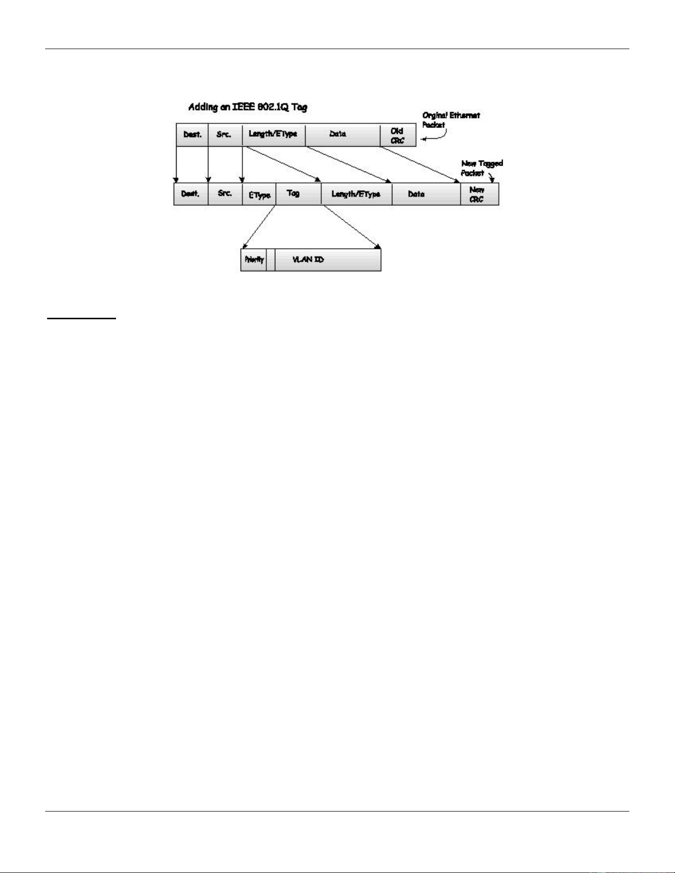
xStack® DGS-3420 Series Layer 2 Managed Stackable Gigabit Switch Web UI Reference Guide
81
The EtherType and VLAN ID are inserted after the MAC source address, but before the original EtherType/Length or
Logical Link Control. Because the packet is now a bit longer than it was originally, the Cyclic Redundancy Check (CRC)
must be recalculated.
Figure 4-3 Adding an IEEE 802.1Q Tag
Port VLAN ID
Packets that are tagged (are carrying the 802.1Q VID information) can be transmitted from one 802.1Q compliant
network device to another with the VLAN information intact. This allows 802.1Q VLANs to span network devices (and
indeed, the entire network, if all network devices are 802.1Q compliant).
Unfortunately, not all network devices are 802.1Q compliant. These devices are referred to as tag-unaware. 802.1Q
devices are referred to as tag-aware.
Prior to the adoption of 802.1Q VLANs, port-based and MAC-based VLANs were in common use. These VLANs relied
upon a Port VLAN ID (PVID) to forward packets. An untagged packet received on a given port would be assigned that
port’s PVID and then be forwarded to the port that corresponded to the packet’s destination address (found in the
Switch’s forwarding table).
Within the Switch, different PVIDs mean different VLANs (remember that two VLANs cannot communicate without an
external router). So, VLAN identification based upon the PVIDs cannot create VLANs that extend outside a given
switch (or switch stack).
Every physical port on a switch has a PVID. 802.1Q ports are also assigned a PVID, for use within the Switch. If no
VLANs are defined on the Switch, all ports are then assigned to a default VLAN with a PVID equal to 1. Untagged
packets are assigned the PVID of the port on which they were received. Forwarding decisions are based upon this
PVID, in so far as VLANs are concerned. Tagged packets are forwarded according to the VID contained within the tag.
Tag-aware switches must keep a table to relate PVIDs within the Switch to VIDs on the network. The Switch will
compare the VID of a packet to be transmitted to the VID of the port that is to transmit the packet. If the two VIDs are
different, the Switch will drop the packet. Because of the existence of the PVID for untagged packets and the VID for
tagged packets, tag-aware and tag-unaware network devices can coexist on the same network.
A switch port can have only one PVID, but can have as many VIDs as the Switch has memory in its VLAN table to
store them.
Because some devices on a network may be tag-unaware, a decision must be made at each port on a tag-aware
device before packets are transmitted – should the packet to be transmitted have a tag or not? If the transmitting port is
connected to a tag-unaware device, the packet should be untagged. If the transmitting port is connected to a tag-aware
device, the packet should be tagged.

xStack® DGS-3420 Series Layer 2 Managed Stackable Gigabit Switch Web UI Reference Guide
82
Tagging and Untagging
Every port on an 802.1Q compliant switch can be configured as tagging or untagging.
Ports with tagging enabled will put the VID number, priority and other VLAN information into the header of all packets
that flow into and out of it.
If a packet has previously been tagged, the port will not alter the packet, thus keeping the VLAN information intact.
Other 802.1Q compliant devices on the network to make packet-forwarding decisions can then use the VLAN
information in the tag.
Ports with untagging enabled will strip the 802.1Q tag from all packets that flow into and out of those ports. If the
packet doesn’t have an 802.1Q VLAN tag, the port will not alter the packet. Thus, all packets received by and
forwarded by an untagging port will have no 802.1Q VLAN information. (Remember that the PVID is only used
internally within the Switch). Untagging is used to send packets from an 802.1Q-compliant network device to a non-
compliant network device.
Ingress Filtering
A port on a switch where packets are flowing into the Switch and VLAN decisions must be made is referred to as an
ingress port. If ingress filtering is enabled for a port, the Switch will examine the VLAN information in the packet header
(if present) and decide whether or not to forward the packet.
If the packet is tagged with VLAN information, the ingress port will first determine if the ingress port itself is a member
of the VLAN. If it is not, the packet will be dropped. If the ingress port is a member of the 802.1Q VLAN, the Switch
then determines if the destination port is a member of the 802.1Q VLAN. If it is not, the packet is dropped. If the
destination port is a member of the 802.1Q VLAN, the packet is forwarded and the destination port transmits it to its
attached network segment.
If the packet is not tagged with VLAN information, the ingress port will tag the packet with its own PVID as a VID. The
switch then determines if the destination port is a member of the same VLAN (has the same VID) as the ingress port. If
it does not, the packet is dropped. If it has the same VID, the packet is forwarded and the destination port transmits it
on its attached network segment.
This process is referred to as ingress filtering and is used to conserve bandwidth within the Switch by dropping packets
that are not on the same VLAN as the ingress port at the point of reception. This eliminates the subsequent processing
of packets that will just be dropped by the destination port.
Default VLANs
The Switch initially configures one VLAN, VID = 1, called “default.” The factory default setting assigns all ports on the
Switch to the “default.” As new VLANs are configured in Port-based mode, their respective member ports are removed
from the “default.”
Packets cannot cross VLANs. If a member of one VLAN wants to connect to another VLAN, the link must be through
an external router.
NOTE: If no VLANs are configured on the Switch, then all packets will be forwarded to any destination
port. Packets with unknown source addresses will be flooded to all ports. Broadcast and multicast
packets will also be flooded to all ports.
An example is presented below:
VLAN Name VID Switch Ports
System (default)
1
5, 6, 7
Engineering
2
9, 10
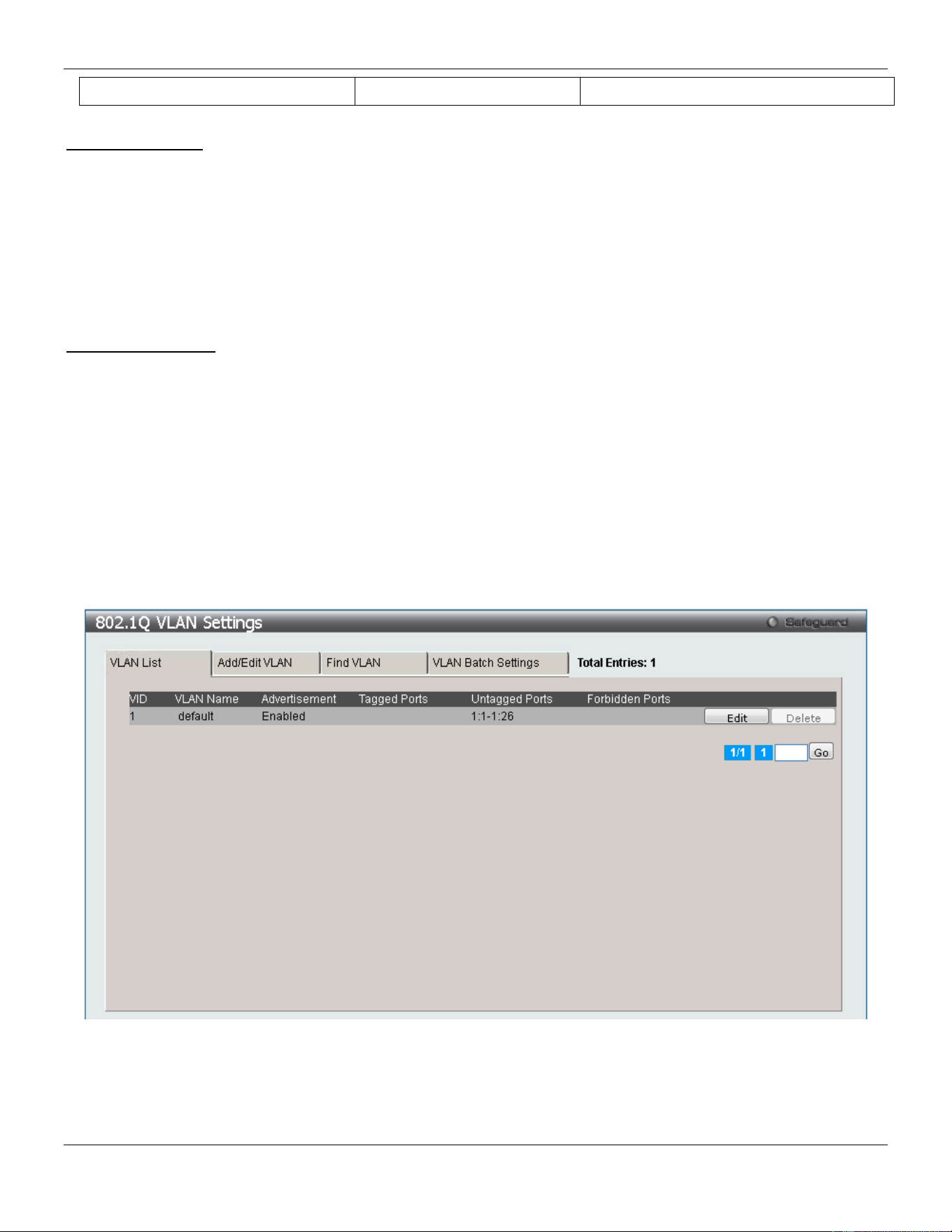
xStack® DGS-3420 Series Layer 2 Managed Stackable Gigabit Switch Web UI Reference Guide
83
Sales
5
1, 2, 3, 4
Port-based VLANs
Port-based VLANs limit traffic that flows into and out of switch ports. Thus, all devices connected to a port are
members of the VLAN(s) the port belongs to, whether there is a single computer directly connected to a switch, or an
entire department.
On port-based VLANs, NICs do not need to be able to identify 802.1Q tags in packet headers. NICs send and receive
normal Ethernet packets. If the packet’s destination lies on the same segment, communications take place using
normal Ethernet protocols. Even though this is always the case, when the destination for a packet lies on another
switch port, VLAN considerations come into play to decide if the packet gets dropped by the Switch or delivered.
VLAN Segmentation
Take for example a packet that is transmitted by a machine on Port 1 that is a member of VLAN 2. If the destination
lies on another port (found through a normal forwarding table lookup), the Switch then looks to see if the other port
(Port 10) is a member of VLAN 2 (and can therefore receive VLAN 2 packets). If Port 10 is not a member of VLAN 2,
then the packet will be dropped by the Switch and will not reach its destination. If Port 10 is a member of VLAN 2, the
packet will go through. This selective forwarding feature based on VLAN criteria is how VLANs segment networks. The
key point being that Port 1 will only transmit on VLAN 2.
802.1Q VLAN Settings
The VLAN List tab lists all previously configured VLANs by VLAN ID and VLAN Name.
To view the following window, click L2 Features > VLAN > 802.1Q VLAN Settings, as show below:
Figure 4-4 802.1Q VLAN Settings –VLAN List Tab window
Click the Edit button to re-configure the specific entry.
Click the Delete button to remove the specific entry.
Enter a page number and click the Go button to navigate to a specific page when multiple pages exist.
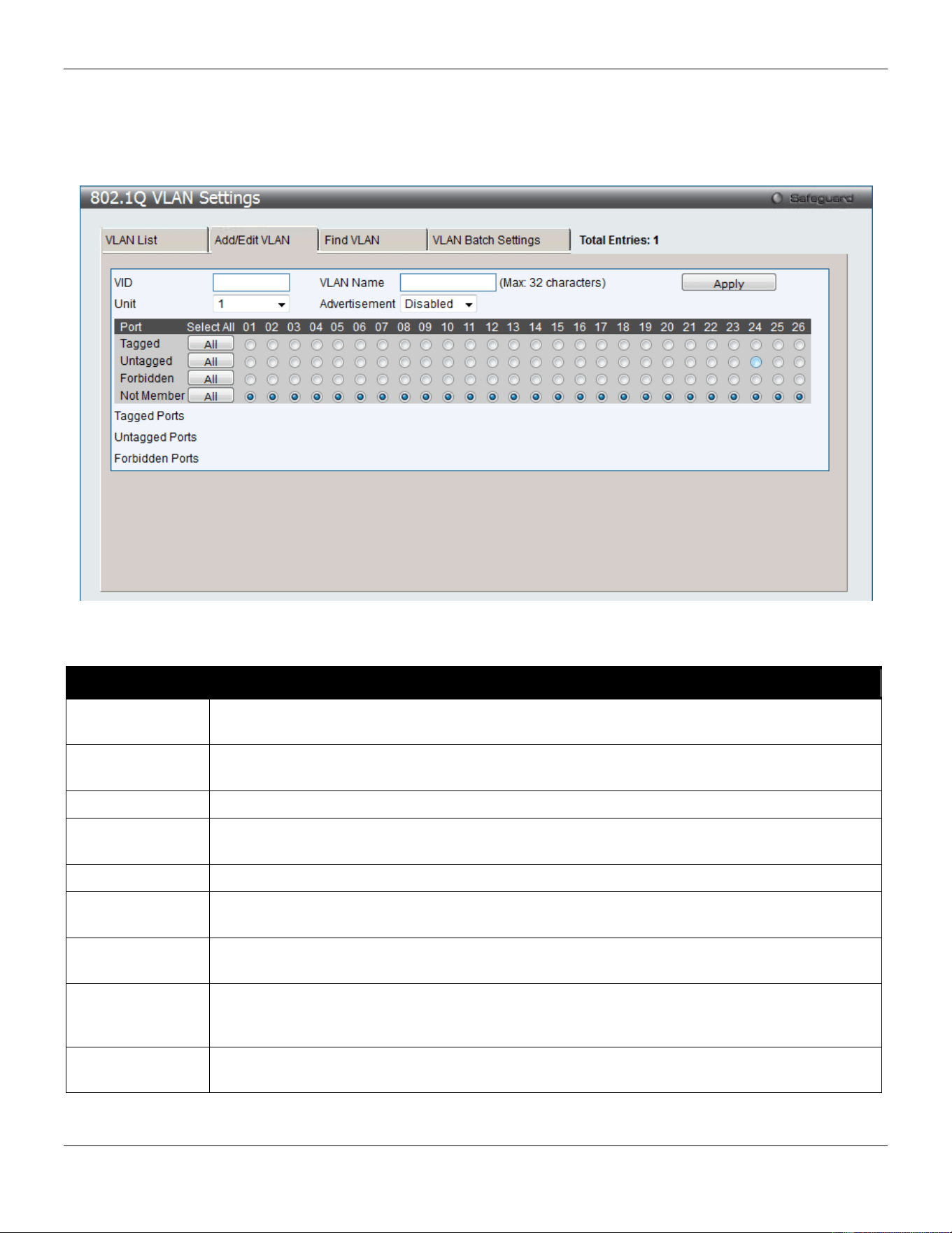
xStack® DGS-3420 Series Layer 2 Managed Stackable Gigabit Switch Web UI Reference Guide
84
To create a new 802.1Q VLAN or modify an existing 802.1Q VLAN, click the Add/Edit VLAN tab.
A new tab will appear, as shown below, to configure the port settings and to assign a unique name and number to the
new VLAN.
Figure 4-5 802.1Q VLAN Settings – Add/Edit VLAN Tab window
The fields that can be configured are described below:
Parameter Description
VID Allow the entry of a VLAN ID or displays the VLAN ID of an existing VLAN in the Add/Edit
VLAN tab. VLANs can be identified by either the VID or the VLAN name.
VLAN Name Allow the entry of a name for the new VLAN or for editing the VLAN name in the Add/Edit
VLAN tab.
Unit
Select the unit you wish to configure.
Advertisement
Enable this function to allow the Switch sending out GVRP packets to outside sources,
notifying that they may join the existing VLAN.
Port
Display all ports of the Switch for the configuration option.
Tagged
Specify the port as 802.1Q tagging. Clicking the radio button will designate the port as tagged.
Click the All button to select all ports.
Untagged
Specify the port as 802.1Q untagged. Clicking the radio button will designate the port as
untagged. Click the All button to select all ports.
Forbidden
Click the radio button to specify the port as not being a member of the VLAN and that the port
is forbidden from becoming a member of the VLAN dynamically. Click the All button to select
all ports.
Not Member
Click the radio button to allow an individual port to be specified as a non-VLAN member. Click
the All button to select all ports.
Click the Apply button to accept the changes made.
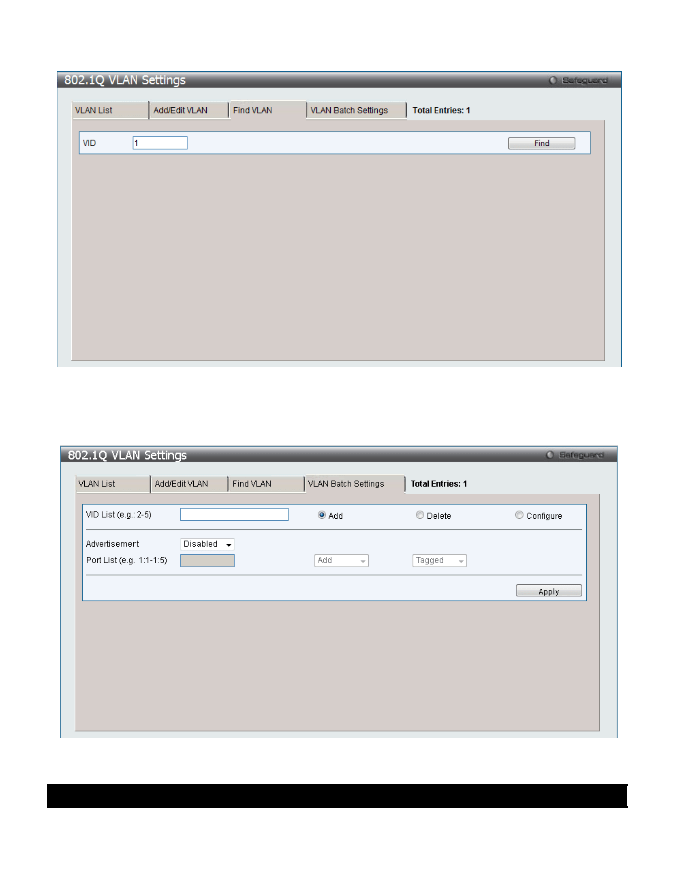
xStack® DGS-3420 Series Layer 2 Managed Stackable Gigabit Switch Web UI Reference Guide
85
To search for a VLAN, click the Find VLAN tab. A new tab will appear, as shown below.
Figure 4-6 802.1Q VLAN Settings – Find VLAN Tab window
Enter the VLAN ID number in the field offered and then click the Find button. You will be redirected to the VLAN List
tab.
To create, delete and configure a VLAN Batch entry click the VLAN Batch Settings tab, as shown below.
Figure 4-7 802.1Q VLAN Settings – VLAN Batch Settings Tab window
The fields that can be configured are described below:
Parameter Description
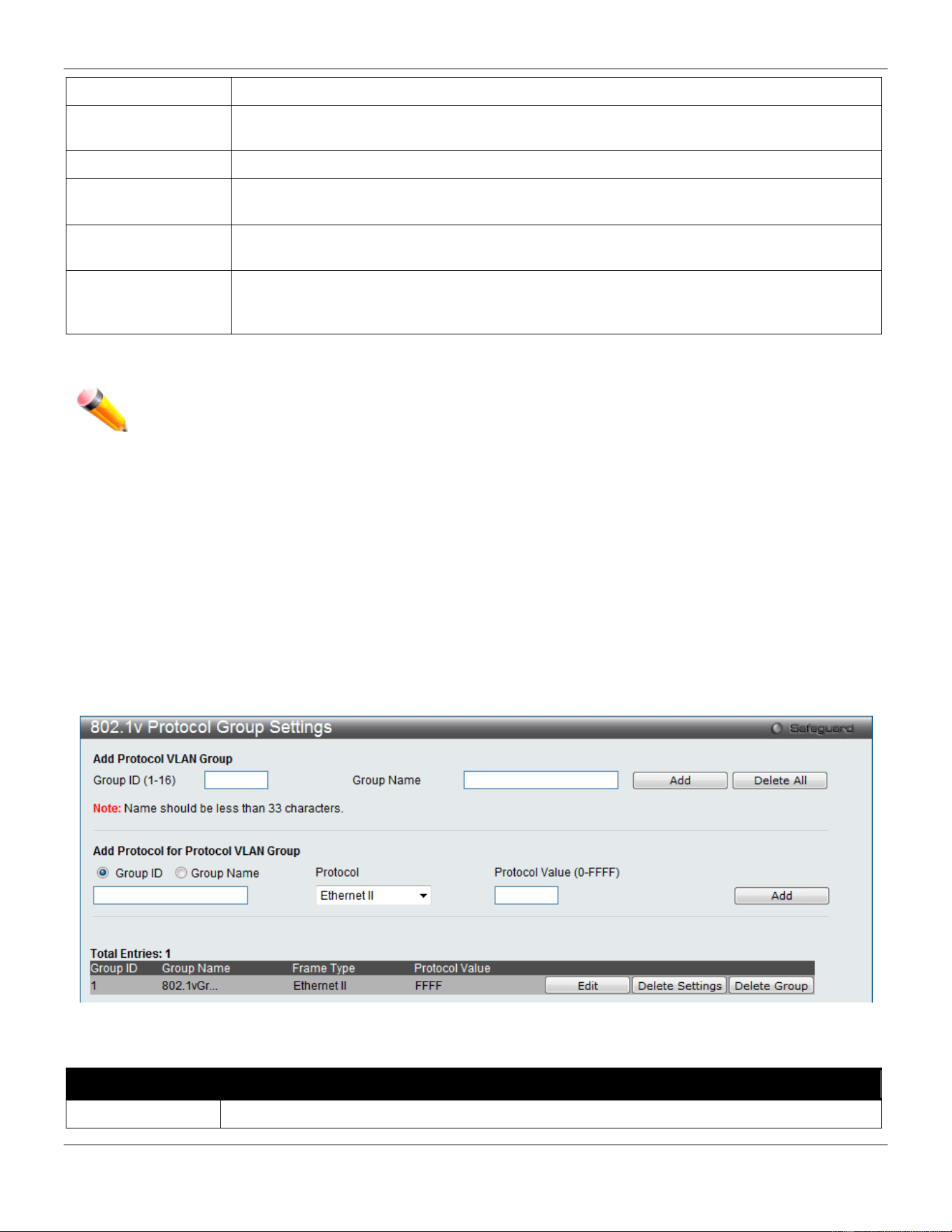
xStack® DGS-3420 Series Layer 2 Managed Stackable Gigabit Switch Web UI Reference Guide
86
VID List
Enter a VLAN ID List that can be added, deleted or configured.
Advertisement
Enabling this function will allow the Switch to send out GVRP packets to outside sources,
notifying that they may join the existing VLAN.
Port List
Allows an individual port list to be added or deleted as a member of the VLAN.
Tagged
Specify the port as 802.1Q tagged. Use the drop-down menu to designate the port as
tagged.
Untagged
Specify the port as 802.1Q untagged. Use the drop-down menu to designate the port as
untagged.
Forbidden
Specify the port as not being a member of the VLAN and that the port is forbidden from
becoming a member of the VLAN dynamically. Use the drop-down menu to designate the
port as forbidden.
Click the Apply button to accept the changes made.
NOTE: The Switch supports up to 4k static VLAN entries.
802.1v Protocol VLAN
802.1v Protocol Group Settings
The user can create Protocol VLAN groups and add protocols to that group. The 802.1v Protocol VLAN Group Settings
support multiple VLANs for each protocol and allows the user to configure the untagged ports of different protocols on
the same physical port. For example, it allows the user to configure an 802.1Q and 802.1v untagged port on the same
physical port. The lower half of the table displays any previously created groups.
To view the following window, click L2 Features > VLAN > 802.1v Protocol VLAN > 802.1v Protocol Group
Settings, as show below:
Figure 4-8 802.1v Protocol Group Settings window
The fields that can be configured are described below:
Parameter Description
Group ID
Select an ID number for the group, between 1 and 16.
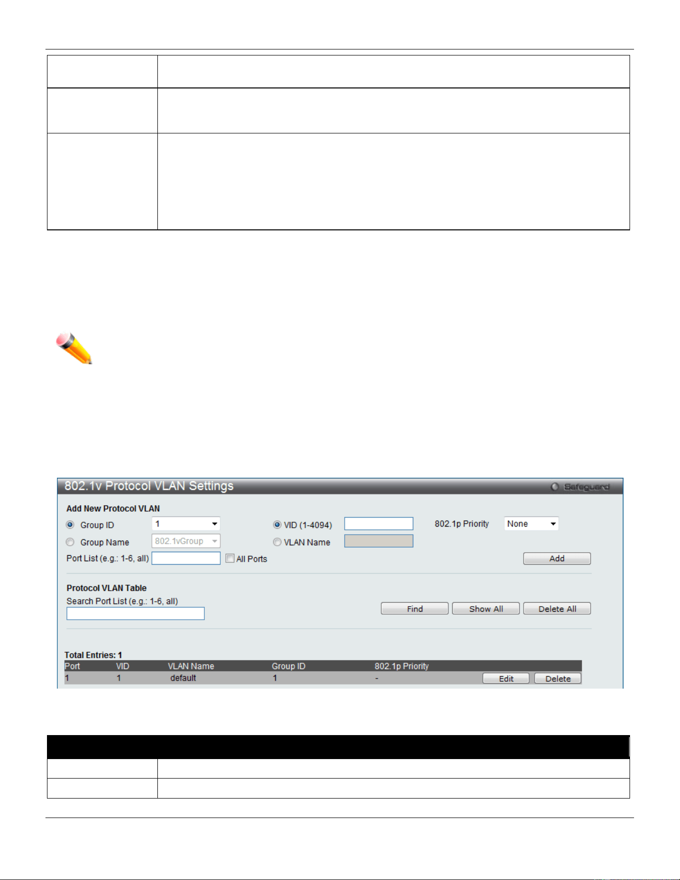
xStack® DGS-3420 Series Layer 2 Managed Stackable Gigabit Switch Web UI Reference Guide
87
Group Name
This is used to identify the new Protocol VLAN group. Type an alphanumeric string of up to
32 characters.
Protocol
This function maps packets to protocol-defined VLANs by examining the type octet within the
packet header to discover the type of protocol associated with it. Use the drop-down menu to
toggle between Ethernet II, IEEE802.3 SNAP, and IEEE802.3 LLC.
Protocol Value
Enter a value for the Group. The protocol value is used to identify a protocol of the frame type
specified. The form of the input is 0x0 to 0xffff. Depending on the frame type, the octet string
will have one of the following values: For Ethernet II, this is a 16-bit (2-octet) hex value. For
example, IPv4 is 800, IPv6 is 86dd, ARP is 806, etc. For IEEE802.3 SNAP, this is a 16-bit (2-
octet) hex value. For IEEE802.3 LLC, this is a 2-octet IEEE 802.2 Link Service Access Point
(LSAP) pair. The first octet is for Destination Service Access Point (DSAP) and the second
octet is for Source.
Click the Add button to add a new entry based on the information entered.
Click the Delete All button to remove all the entries based on the information entered.
Click the Edit button to re-configure the specific entry.
Click the Delete Settings button to remove the Protocol for the Protocol VLAN Group information for the specific entry.
Click the Delete Group button to remove the entry completely.
NOTE: The Group name value should be less than 33 characters.
802.1v Protocol VLAN Settings
The user can configure Protocol VLAN settings. The lower half of the table displays any previously created settings.
To view the following window, click L2 Features > VLAN > 802.1v protocol VLAN > 802.1v Protocol VLAN Settings,
as show below:
Figure 4-9 802.1v Protocol VLAN Settings window
The fields that can be configured are described below:
Parameter Description
Group ID
Select a previously configured Group ID from the drop-down menu.
Group Name
Select a previously configured Group Name from the drop-down menu.
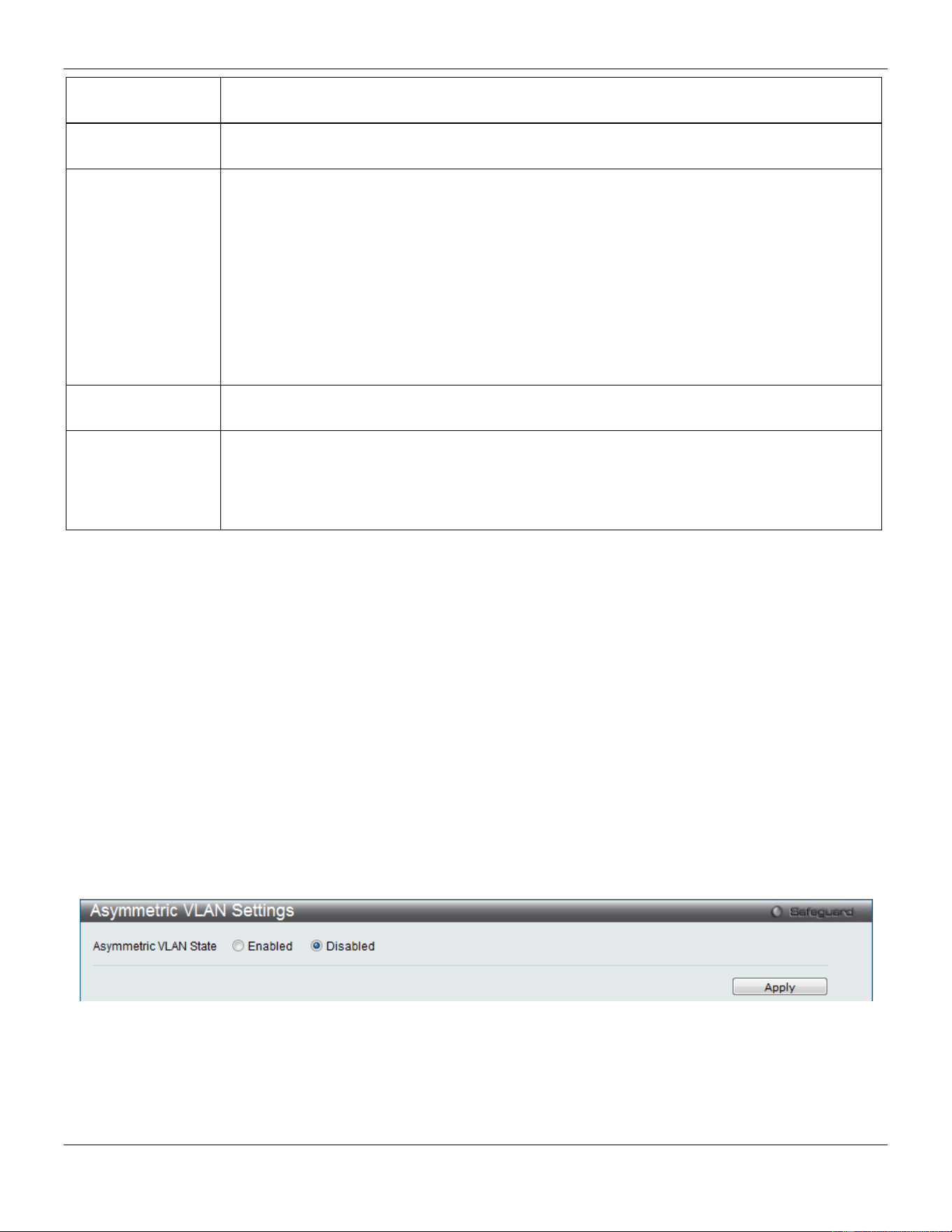
xStack® DGS-3420 Series Layer 2 Managed Stackable Gigabit Switch Web UI Reference Guide
88
VID (1-4094)
This is the VLAN ID that, along with the VLAN Name, identifies the VLAN the user wishes to
create.
VLAN Name
This is the VLAN Name that, along with the VLAN ID, identifies the VLAN the user wishes to
create.
802.1p Priority
This parameter is specified if you want to re-write the 802.1p default priority previously set in
the Switch, which is used to determine the CoS queue to which packets are forwarded to.
Once this field is specified, packets accepted by the Switch that match this priority are
forwarded to the CoS queue specified previously by the user.
Click the corresponding box if you want to set the 802.1p default priority of a packet to the
value entered in the Priority (0-7) field, which meets the criteria specified previously in this
command, before forwarding it on to the specified CoS queue. Otherwise, a packet will have
its incoming 802.1p user priority re-written to its original value before being forwarded by the
Switch.
For more information on priority queues, CoS queues and mapping for 802.1p, see the QoS
section of this manual.
Port List
Select the specified ports you wish to configure by entering the port number in this field, or
tick the All Ports check box.
Search Port List
This function allows the user to search all previously configured port list settings and display
them on the lower half of the table. To search for a port list enter the port number you wish to
view and click Find. To display all previously configured port lists on the bottom half of the
screen click the Show All button, to clear all previously configured lists click the Delete All
button.
Click the Add button to add a new entry based on the information entered.
Click the Find button to locate a specific entry based on the information entered.
Click the Show All button to display all the Protocol VLANs configured.
Click the Delete All button to remove all the entries listed.
Click the Edit button to re-configure the specific entry.
Click the Delete button to remove the specific entry.
Asymmetric VLAN Settings
Shared VLAN Learning is a primary example of the requirement for Asymmetric VLANs. Under normal circumstances,
a pair of devices communicating in a VLAN environment will both send and receive using the same VLAN; however,
there are some circumstances in which it is convenient to make use of two distinct VLANs, one used for A to transmit
to B and the other used for B to transmit to A in these cases Asymmetric VLANs are needed. An example of when this
type of configuration might be required, would be if the client was on a distinct IP subnet, or if there was some
confidentiality-related need to segregate traffic between the clients.
To view this window click L2 Features > VLAN > Asymmetric VLAN Settings, as show below:
Figure 4-10 Asymmetric VLAN Settings window
Click Apply to implement changes.
GVRP
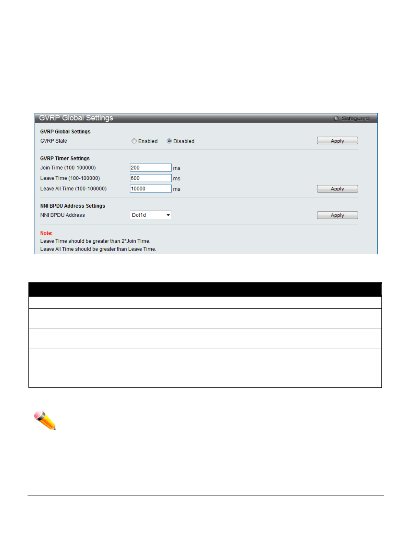
xStack® DGS-3420 Series Layer 2 Managed Stackable Gigabit Switch Web UI Reference Guide
89
GVRP Global Settings
Users can determine whether the Switch will share its VLAN configuration information with other GARP VLAN
Registration Protocol (GVRP) enabled switches. In addition, Ingress Checking can be used to limit traffic by filtering
incoming packets whose VID does not match the PVID of the port. Results can be seen in the table under the
configuration settings.
To view the following window, click L2 Features > VLAN > GVRP > GVRP Global Settings, as show below:
Figure 4-11 GVRP Global Settings window
The fields that can be configured are described below:
Parameter Description
GVRP State
Click the radio buttons to enable or disable the GVRP State.
Join Time
(100-100000)
Enter the Join Time value in milliseconds.
Leave Time
(100-100000)
Enter the Leave Time value in milliseconds.
Leave All Time
(100-100000)
Enter the Leave All Time value in milliseconds.
NNI BPDU Address
Used to determine the BPDU protocol address for GVRP in service provide site. It can use
802.1d GVRP address or 802.1ad service provider GVRP address.
Click the Apply button to accept the changes made for each individual section.
NOTE: The Leave Time value should be greater than twice the Join Time value. The Leave All Time
value should be greater than the Leave Time value.
GVRP Port Settings
On this page the user can configure the GVRP port parameters.
To view the following window, click L2 Features > VLAN > GVRP > GVRP Port Settings, as show below:
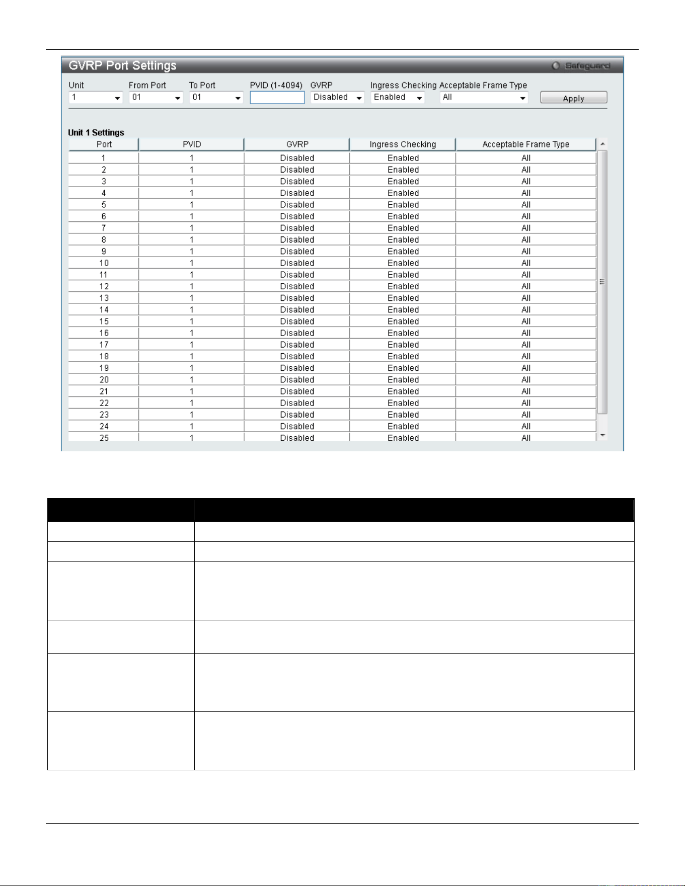
xStack® DGS-3420 Series Layer 2 Managed Stackable Gigabit Switch Web UI Reference Guide
90
Figure 4-12 GVRP Port Settings window
The fields that can be configured are described below:
Parameter Description
Unit
Select the unit you wish to configure.
From Port / To Port
Select the starting and ending ports to use.
PVID (1-4094)
This field is used to manually assign a PVID to a VLAN. The Switch's default is to
assign all ports to the default VLAN with a VID of 1.The PVID is used by the port to
tag internally outgoing, untagged packets, and to make filtering decisions about
incoming packets.
GVRP
The GARP VLAN Registration Protocol (GVRP) enables the port to dynamically
become a member of a VLAN. GVRP is Disabled by default.
Ingress Checking
This drop-down menu allows the user to enable the port to compare the VID tag of an
incoming packet with the port’s VLAN setting, including PVID and tag LAN settings. If
enable ingress checking and the reception port is not the member port of the frame’s
VLAN, the frame shall be discarded.
Acceptable Frame Type
This field denotes the type of frame that will be accepted by the port. The user may
choose between Tagged Only, which means only VLAN tagged frames will be
accepted, and All, which mean both tagged and untagged frames will be accepted. All
is enabled by default.
Click the Apply button to accept the changes made.
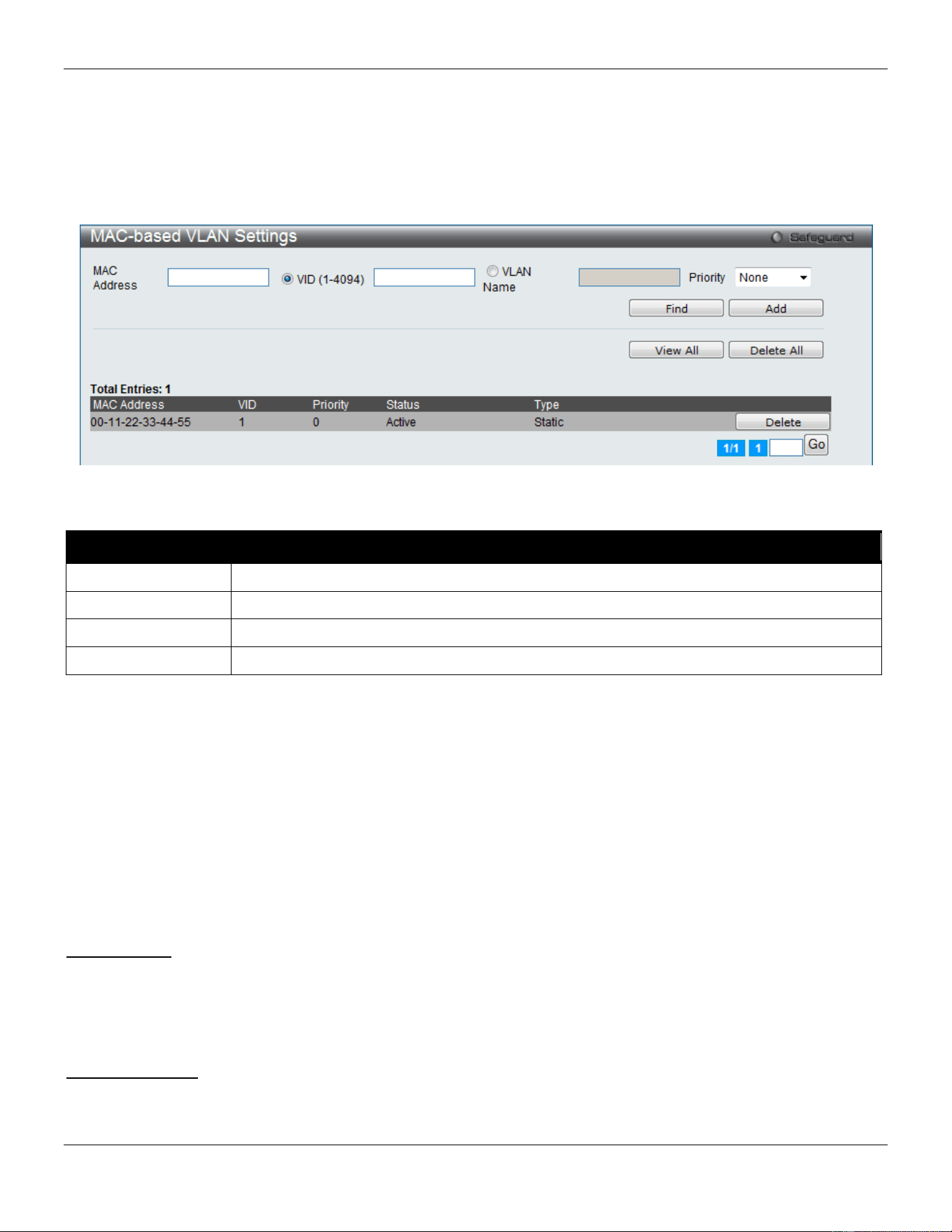
xStack® DGS-3420 Series Layer 2 Managed Stackable Gigabit Switch Web UI Reference Guide
91
MAC-based VLAN Settings
Users can create new MAC-based VLAN entries, search and delete existing entries. When a static MAC-based VLAN
entry is created for a user, the traffic from this user will be able to be serviced under the specified VLAN regardless of
the authentication function operating on this port.
To view the following window, click L2 Features > VLAN > MAC-based VLAN Settings, as show below:
Figure 4-13 MAC-based VLAN Settings
The fields that can be configured are described below:
Parameter Description
MAC Address
Enter the Unicast MAC address.
VID (1-4094)
Select this option and enter the VLAN ID.
VLAN Name
Select this option and enter the VLAN name of a previously configured VLAN.
Priority
Use the drop-down menu to select the priority that is assigned to untagged packets.
Click the Find button to locate a specific entry based on the information entered.
Click the Add button to add a new entry based on the information entered.
Click the View All button to display all the existing entries.
Click the Delete All button to remove all the entries listed.
Click the Delete button to remove the specific entry.
Private VLAN Settings
A private VLAN is comprised of a primary VLAN, up to one isolated VLAN, and a number of community VLANs. A
private VLAN ID is presented by the VLAN ID of the primary VLAN. The command used to associate or de-associate a
secondary VLAN with a primary VLAN.
Isolated VLAN
An isolated VLAN is a secondary VLAN whose distinctive characteristic is that all hosts connected to its ports are
isolated at Layer 2. Therefore, its primary advantage is that it allows a design based on private VLANs to use a total of
only two VLAN identifiers to provide port isolation and serve any number of end users. A private VLAN has only one
isolated VLAN.
Community VLAN
A community VLAN is a secondary VLAN that is associated with a group of ports that connects to a certain
"community" of end devices with mutual trust relationships. There can be multiple distinct community VLANs in a
private VLAN domain.
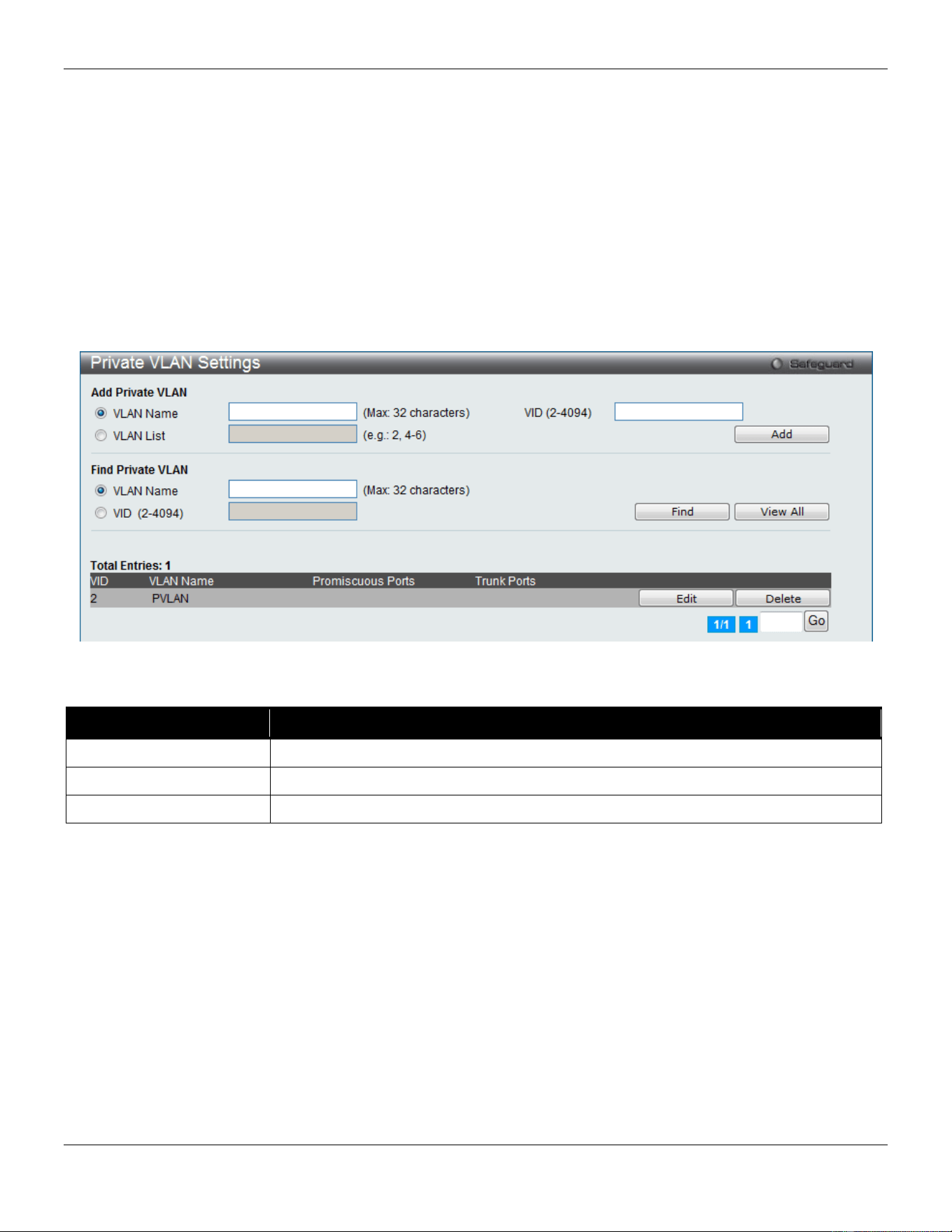
xStack® DGS-3420 Series Layer 2 Managed Stackable Gigabit Switch Web UI Reference Guide
92
A secondary VLAN cannot be associated with multiple primary VLANs. The untagged member port of the primary
VLAN is named as the promiscuous port. The tagged member port of the primary VLAN is named as the trunk port. A
promiscuous port of a private VLAN cannot be promiscuous port of other private VLANs. The primary VLAN member
port cannot be a secondary VLAN member at the same time, or vice versa. A secondary VLAN can only have the
untagged member port. The member port of a secondary VLAN cannot be member port of other secondary VLAN at
the same time. When a VLAN is associated with a primary VLAN as the secondary VLAN, the promiscuous port of the
primary VLAN will behave as the untagged member of the secondary VLAN, and the trunk port of the primary VLAN
will behave as the tagged member of the secondary VLAN. A secondary VLAN cannot be specified with advertisement.
Only the primary VLAN can be configured as a layer 3 interface. The private VLAN member port cannot be configured
with the traffic segmentation function.
This window allows the user to configure the private VLAN parameters.
To view the following window, click L2 Features > VLAN > Private VLAN Settings, as show below:
Figure 4-14 Private VLAN Settings window
The fields that can be configured are described below:
Parameter Description
VLAN Name
Enter a VLAN name.
VID (2-4094)
Enter a VID value.
VLAN List
Enter a list of VLAN ID.
Click the Add button to add a new entry based on the information entered.
Click the Find button to locate a specific entry based on the information entered.
Click the View All button to display all the existing entries.
Click the Edit button to configure the secondary VLAN.
Click the Delete button to remove the specific entry.
Click the Edit button to see the following window.
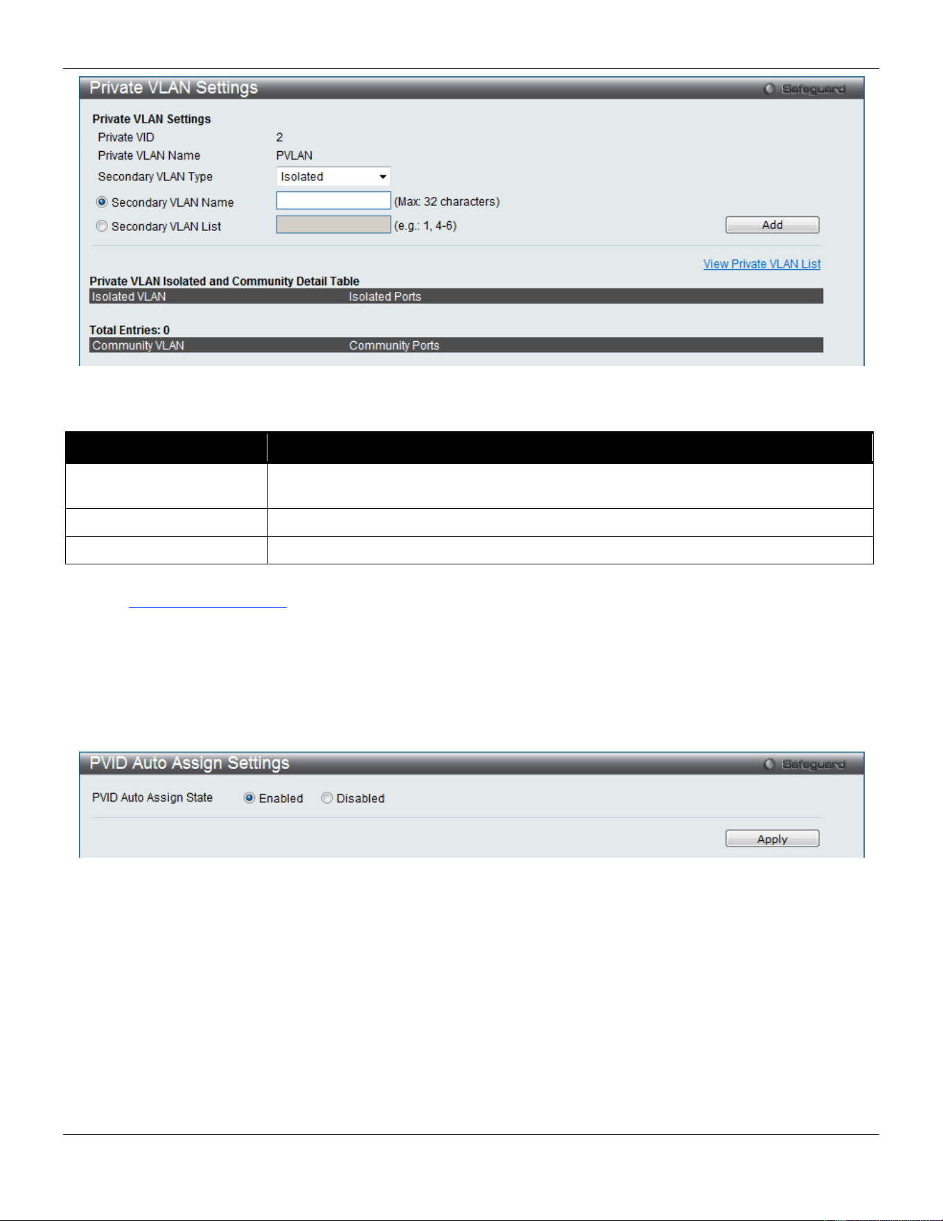
xStack® DGS-3420 Series Layer 2 Managed Stackable Gigabit Switch Web UI Reference Guide
93
Figure 4-15 Private VLAN Settings - Edit window
The fields that can be configured are described below:
Parameter Description
Secondary VLAN Type Use the drop-down menu to select secondary VLAN type between Isolated or
Community.
Secondary VLAN Name
Enter a secondary VLAN name.
Secondary VLAN List
Enter a list of secondary VLAN ID.
Click the Add button to add a new entry based on the information entered.
Click the View Private VLAN List link to view all the private VLAN.
PVID Auto Assign Settings
This window is used to enable or disable PVID Auto Assign Status. The default setting is enabled.
To view the following window, click L2 Features > VLAN > PVID Auto Assign Settings, as show below:
Figure 4-16 PVID Auto Assign Settings window
Click the Apply button to accept the changes made.
Subnet VLAN
Subnet VLAN Settings
A subnet VLAN entry is an IP subnet-based VLAN classification rule. If an untagged or priority-tagged IP packet is
received on a port, its source IP address will be used to match the subnet VLAN entries. If the source IP is in the
subnet of an entry, the packet will be classified to the VLAN defined for this subnet.
The user can configure the subnet VLAN parameters here.
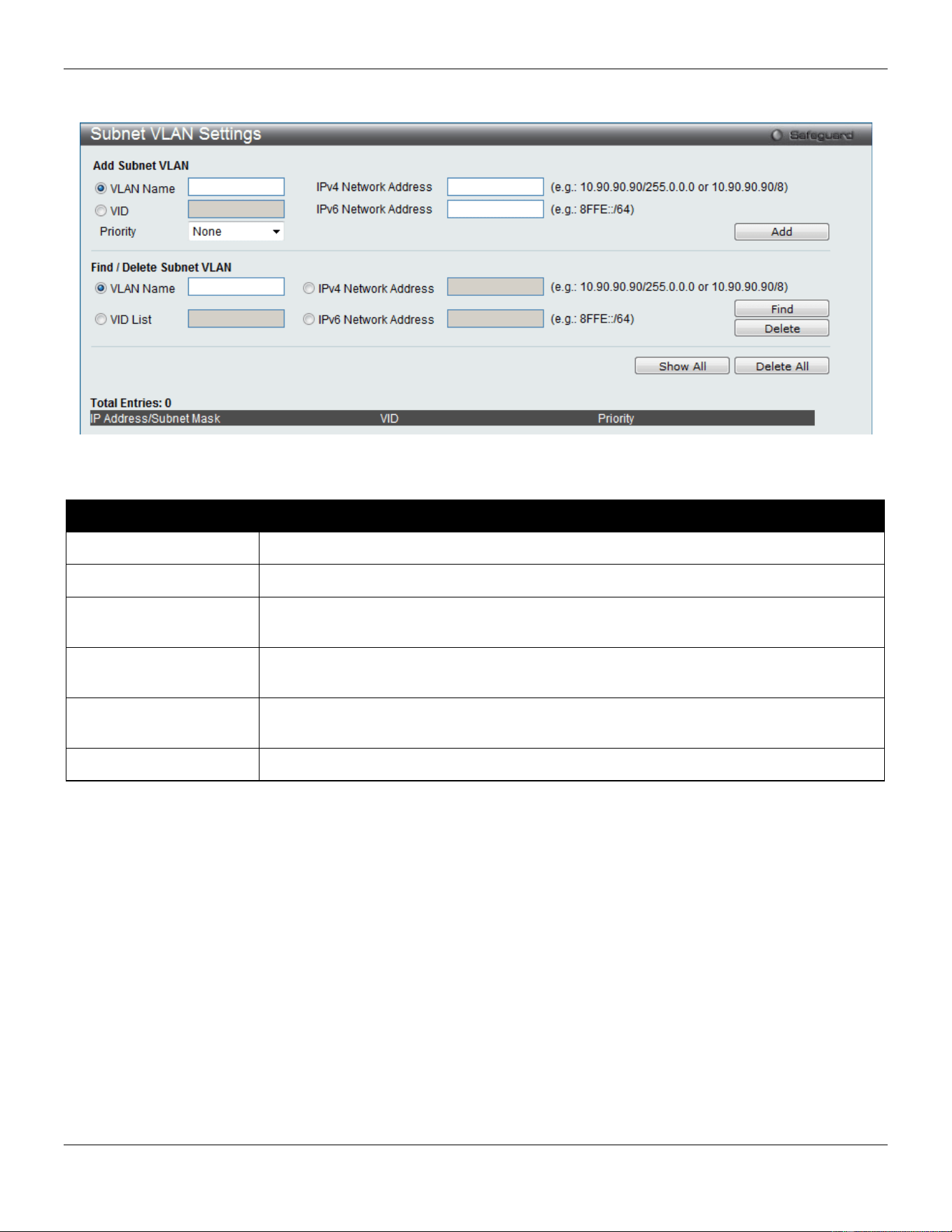
xStack® DGS-3420 Series Layer 2 Managed Stackable Gigabit Switch Web UI Reference Guide
94
To view the following window, click L2 Features > VLAN > Subnet VLAN > Subnet VLAN Settings, as show below:
Figure 4-17 Subnet VLAN Settings Window
The fields that can be configured are described below:
Parameter Description
VLAN Name
Enter a VLAN Name.
VID
Enter a VLAN ID.
IPv4 Network Address
The user can enter the IPv4 address used in here. Remember to include the subnet
mask using the / notation.
IPv6 Network Address
The user can enter the IPv6 address used in here. Remember to include the subnet
mask using the / notation.
Priority Specifies the Subnet VLAN priority value used here. Options to choose from are None,
and 0 to 7.
VID List
Enter a list of VLAN IDs.
Click the Add button to add a new entry based on the information entered.
Click the Find button to locate a specific entry based on the information entered.
Click the Delete button to remove the specific entry based on the information entered.
Click the Show All button to display all the existing entries.
Click the Delete All button to remove all the entries listed.
VLAN Precedence Settings
This window is used to configure VLAN precedence settings.
To view the following window, click L2 Features > VLAN > Subnet VLAN > VLAN Precedence Settings, as show
below:
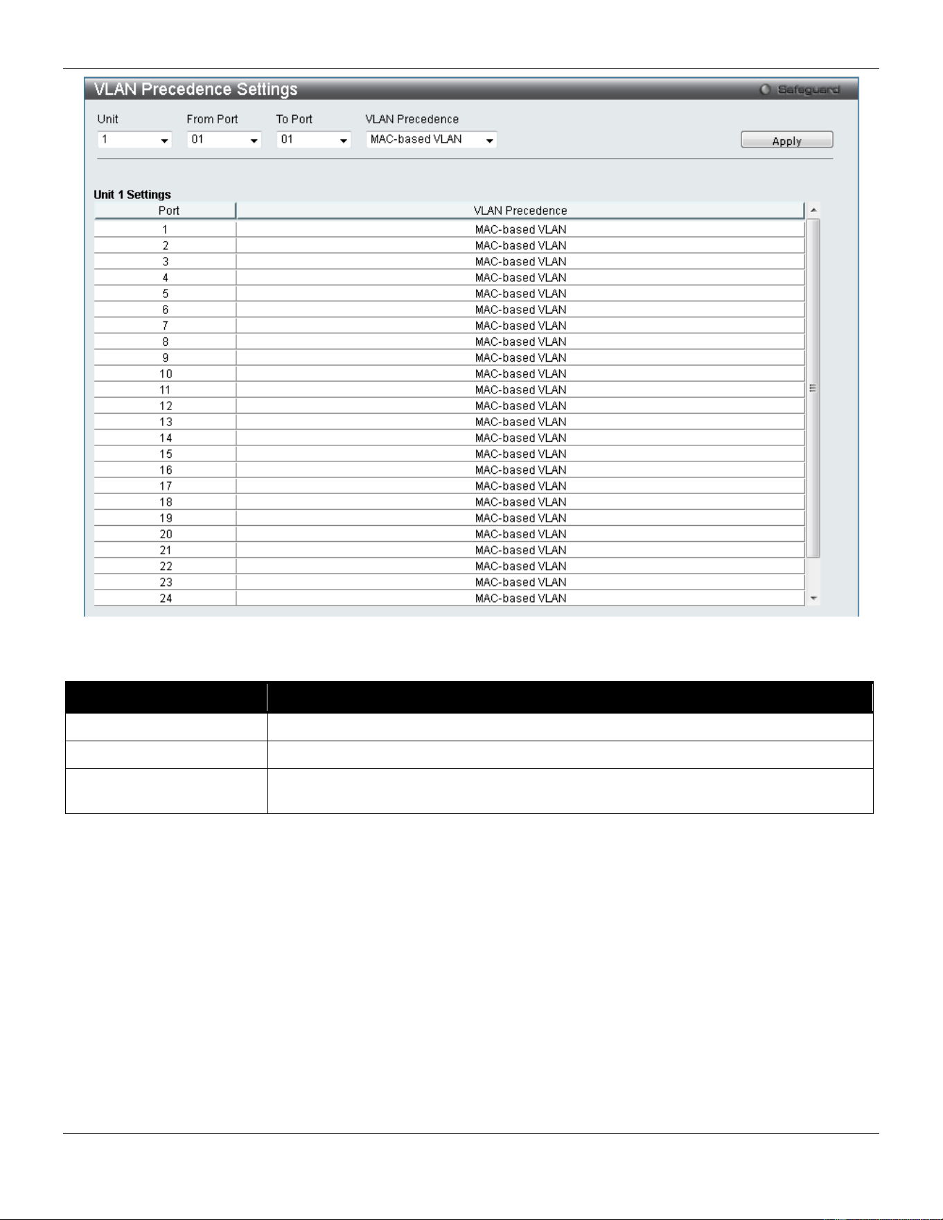
xStack® DGS-3420 Series Layer 2 Managed Stackable Gigabit Switch Web UI Reference Guide
95
Figure 4-18 VLAN Precedence Settings window
The fields that can be configured are described below:
Parameter Description
Unit
Select the unit you wish to configure.
From Port / To Port
Select the starting and ending ports to use.
VLAN Precedence Use the drop-down menu to select the VLAN precedence as MAC-based VLAN or
Subnet VLAN.
Click the Apply button to accept the changes made.
Voice VLAN
Voice VLAN Global Settings
Voice VLAN is a VLAN used to carry voice traffic from IP phone. Because the sound quality of an IP phone call will be
deteriorated if the data is unevenly sent, the quality of service (QoS) for voice traffic shall be configured to ensure the
transmission priority of voice packet is higher than normal traffic.
The switches determine whether a received packet is a voice packet by checking its source MAC address. If the
source MAC addresses of packets comply with the organizationally unique identifier (OUI) addresses configured by the
system, the packets are determined as voice packets and transmitted in voice VLAN.
To view the following window, click L2 Features > VLAN > Voice VLAN > Voice VLAN Global Settings, as show
below:
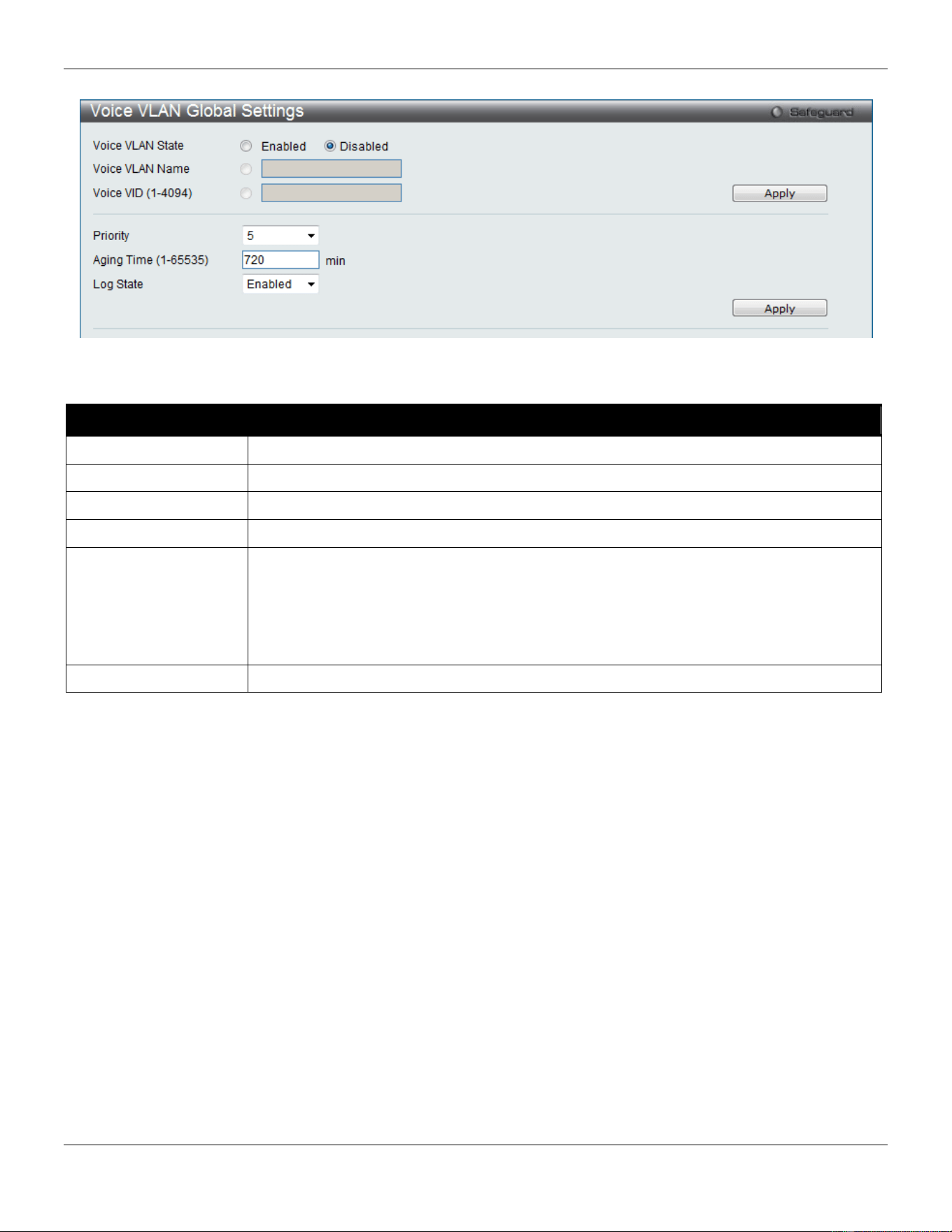
xStack® DGS-3420 Series Layer 2 Managed Stackable Gigabit Switch Web UI Reference Guide
96
Figure 4-19 Voice VLAN Global Settings window
The fields that can be configured are described below:
Parameter Description
Voice VLAN State
The state of the voice VLAN.
Voice VLAN Name
The name of the voice VLAN.
Voice VID (1-4094)
The VLAN ID of the voice VLAN.
Priority
The priority of the voice VLAN, the range is 0 – 7. The default priority is 5.
Aging Time (1-65535)
The aging time to set, the range is 1 – 65535 minutes. The default value is 720 minutes.
The aging time is used to remove a port from voice VLAN if the port is an automatic
VLAN member. When the last voice device stops sending traffic and the MAC address of
this voice device is aged out, the voice VLAN aging timer will be started. The port will be
removed from the voice VLAN after expiration of voice VLAN aging timer. If the voice
traffic resumes during the aging time, the aging timer will be reset and stop.
Log State
Used to enable/disable sending of issue of voice VLAN log.
Click the Apply button to accept the changes made for each individual section.
Voice VLAN Port Settings
This window is used to show the ports voice VLAN information.
To view the following window, click L2 Features > VLAN > Voice VLAN > Voice VLAN Port Settings, as show below:
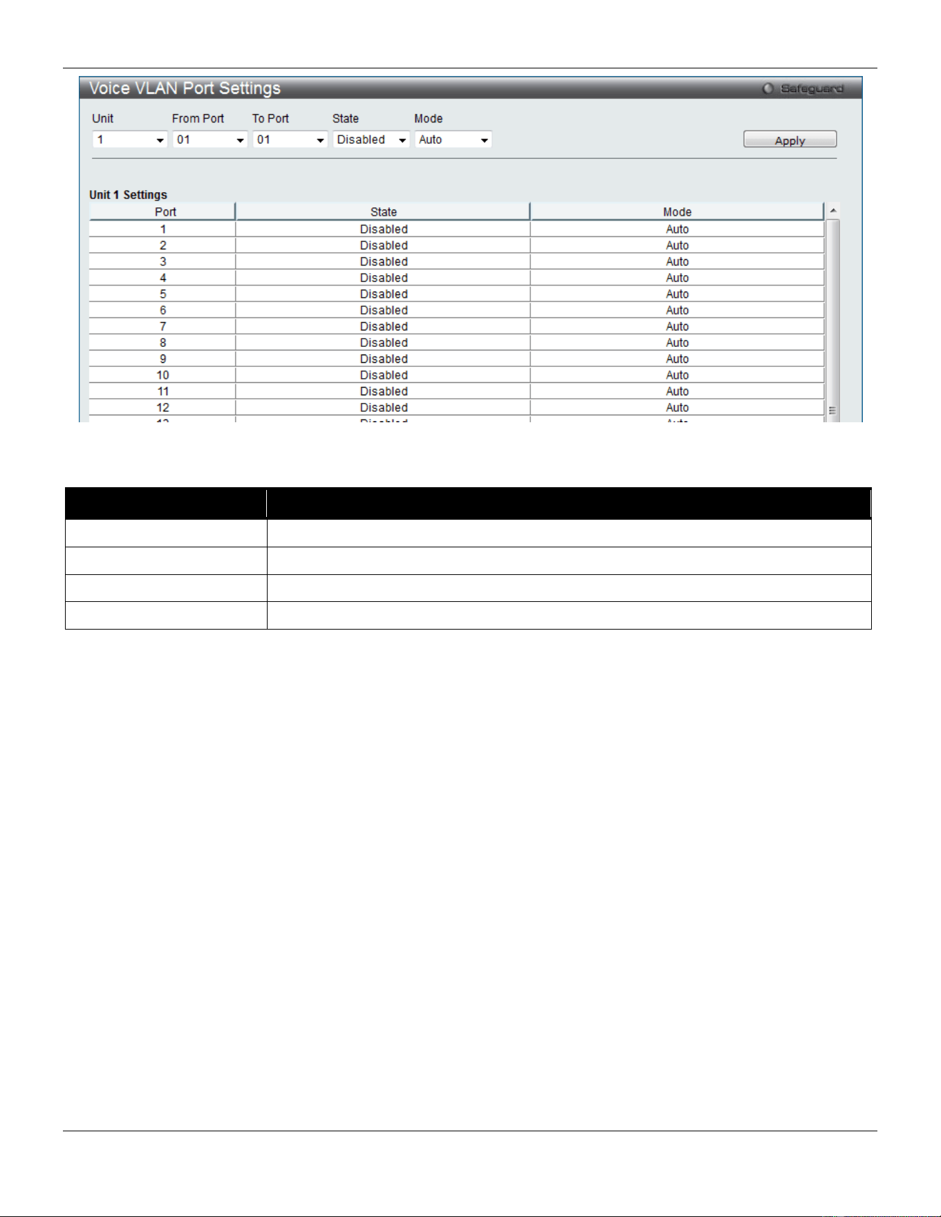
xStack® DGS-3420 Series Layer 2 Managed Stackable Gigabit Switch Web UI Reference Guide
97
Figure 4-20 Voice VLAN Port Settings window
The fields that can be configured are described below:
Parameter
Description
Unit
Select the unit you wish to configure.
From Port / To Port
Here the user can select a range of port to display.
State
Here the user can configure the state of the port.
Mode
Here the user can configure the mode of the port.
Click the Apply button to accept the changes made.
Voice VLAN OUI Settings
This window is used to configure the user-defined voice traffic’s OUI. The OUI is used to identify the voice traffic. There
are a number of pre-defined OUIs. The user can further define the user-defined OUIs if needed. The user-defined OUI
cannot be the same as the pre-defined OUI.
To view the following window, click L2 Features > VLAN > Voice VLAN > Voice VLAN OUI Settings, as show below:
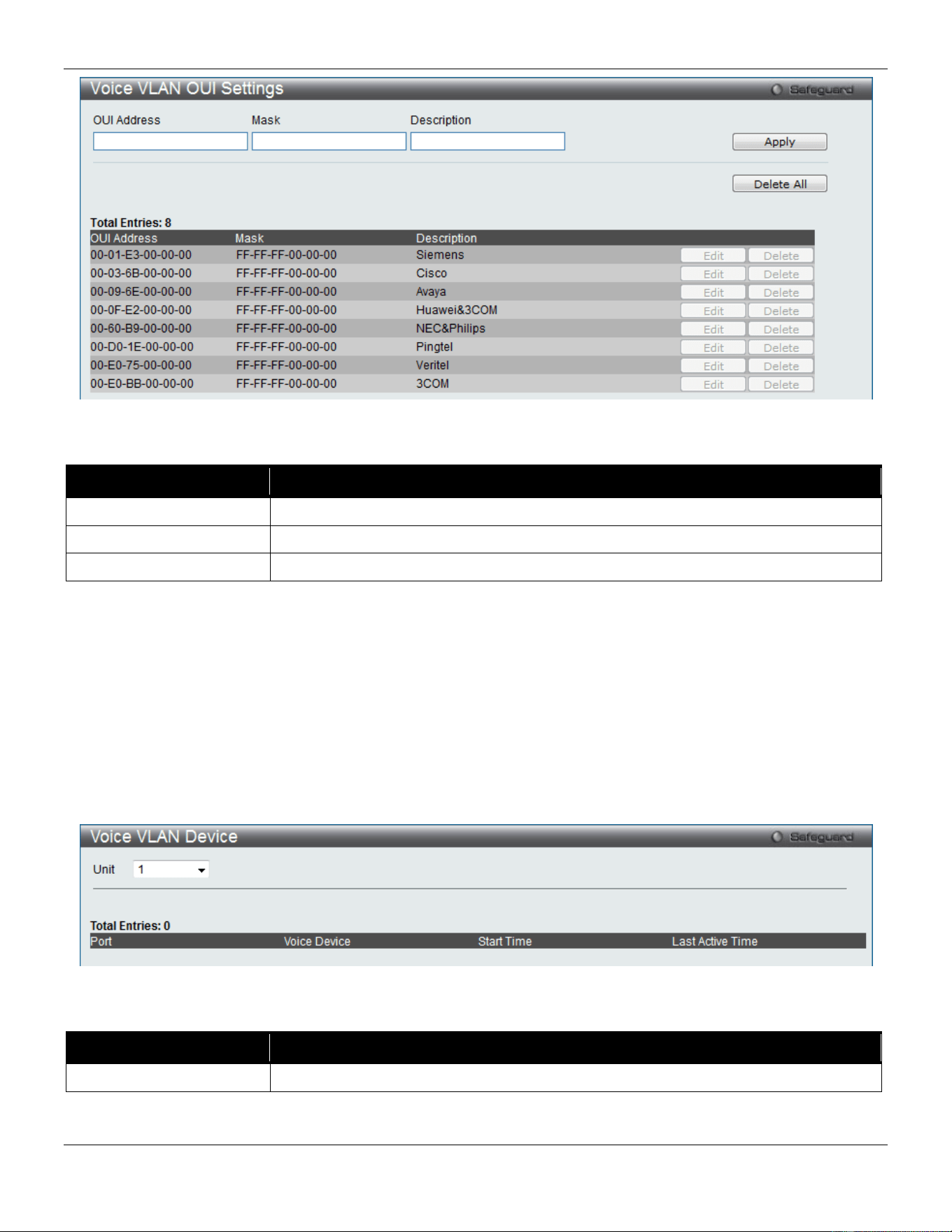
xStack® DGS-3420 Series Layer 2 Managed Stackable Gigabit Switch Web UI Reference Guide
98
Figure 4-21 Voice VLAN OUI Settings window
The fields that can be configured are described below:
Parameter Description
OUI Address
User defined OUI MAC address.
Mask
User defined OUI MAC address mask.
Description
The description for the user defined OUI.
Click the Apply button to accept the changes made.
Click the Delete All button to remove all the user-defined entries listed.
Click the Edit button to re-configure the specific entry.
Click the Delete button to remove the specific entry.
Voice VLAN Device
This window is used to show voice devices that are connected to the ports. The start time is the time when the device
is detected on this port, the activate time is the latest time saw the device sending the traffic.
To view the following window, click L2 Features > VLAN > Voice VLAN > Voice VLAN Device, as show below:
Figure 4-22 Voice VLAN Device window
The fields that can be configured are described below:
Parameter Description
Unit
Select the unit you wish to display.
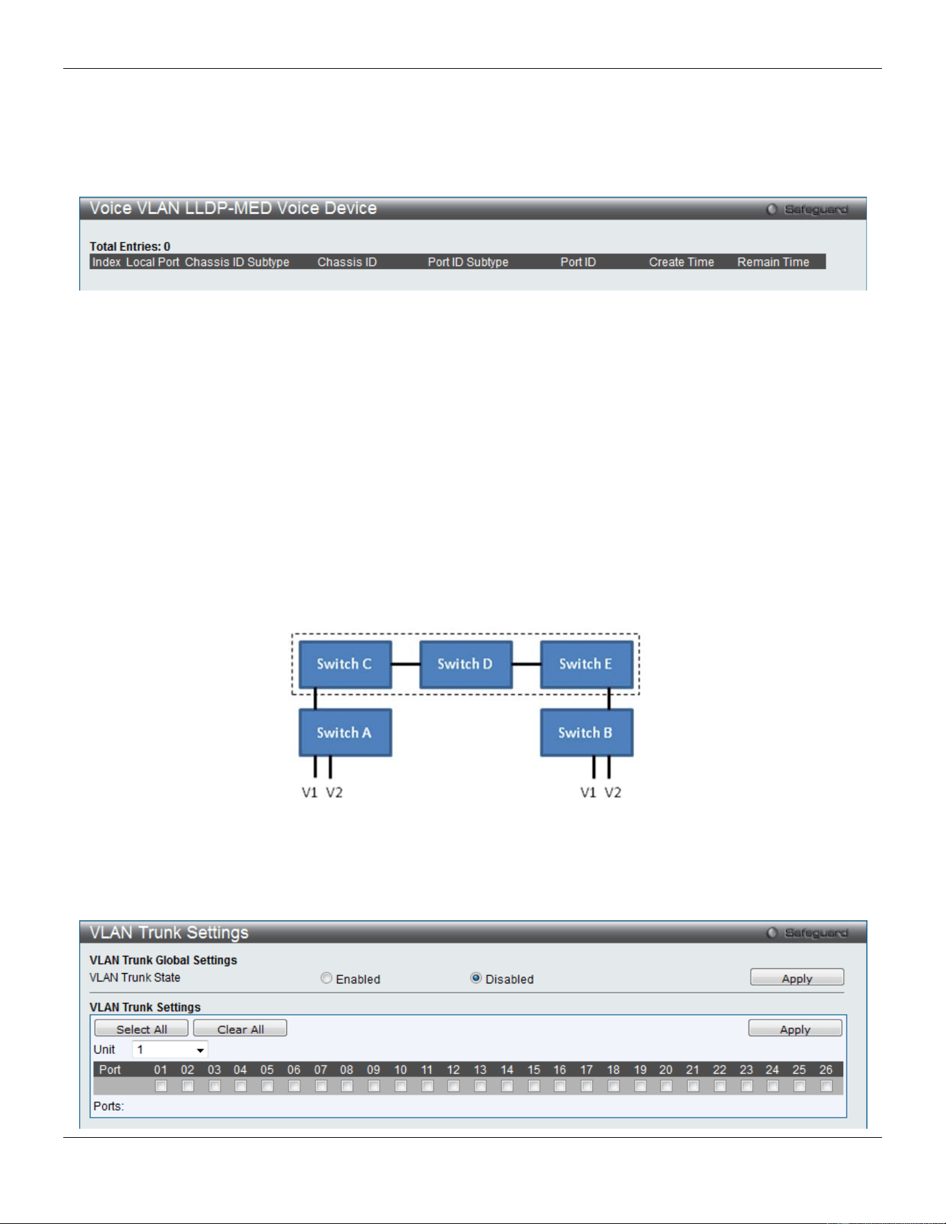
xStack® DGS-3420 Series Layer 2 Managed Stackable Gigabit Switch Web UI Reference Guide
99
Voice VLAN LLDP-MED Voice Device
This window displays the voice VLAN LLDP-MED voice devices connected to the Switch.
To view the following window, click L2 Features > VLAN > Voice VLAN > Voice VLAN LLDP-MED Voice Device, as
show below:
Figure 4-23 Voice VLAN LLDP-MED Voice Device window
Enter a page number and click the Go button to navigate to a specific page when multiple pages exist.
VLAN Trunk Settings
Enable VLAN on a port to allow frames belonging to unknown VLAN groups to pass through that port. This is useful if
you want to set up VLAN groups on end devices without having to configure the same VLAN groups on intermediary
devices.
Suppose you want to create VLAN groups 1 and 2 (V1 and V2) on devices A and B. Without a VLAN Trunk, you must
first configure VLAN groups 1 and 2 on all intermediary switches C, D and E; otherwise they will drop frames with
unknown VLAN group tags. However, with VLAN Trunk enabled on a port(s) in each intermediary switch, you only
need to create VLAN groups in the end devices (A and B). C, D and E automatically allow frames with VLAN group
tags 1 and 2 (VLAN groups that are unknown to those switches) to pass through their VLAN trunking port(s).
Refer to the following figure for an illustrated example.
Figure 4-24 Example of VLAN Trunk
Users can combine a number of VLAN ports together to create VLAN trunks.
To view the following window, click L2 Features > VLAN > VLAN Trunk Settings, as show below:
xStack® DGS-3420 Series Layer 2 Managed Stackable Gigabit Switch Web UI Reference Guide
100
Figure 4-25 VLAN Trunk Settings window
The fields that can be configured are described below:
Parameter Description
VLAN Trunk State
Enable or disable the VLAN trunking global state.
Unit
Select the unit you wish to configure.
Ports The ports to be configured. By clicking the Select All button, all the ports will be included.
By clicking the Clear All button, all the ports will not be included.
Click the Apply button to accept the changes made for each individual section.
Browse VLAN
Users can display the VLAN status for each of the Switch's ports viewed by VLAN. Enter a VID (VLAN ID) in the field at
the top of the window and click the Find button.
To view the following window, click L2 Features > VLAN > Browse VLAN, as show below:
Figure 4-26 Browse VLAN window
Enter a page number and click the Go button to navigate to a specific page when multiple pages exist.
NOTE: The abbreviations used on this page are Tagged Port (T), Untagged Port (U) and Forbidden
Port (F).
Show VLAN Ports
Users can display the VLAN ports of the Switch's viewed by VID. Enter a Port or a Port List in the field at the top of the
window and click the Find button.
To view the following window, click L2 Features > VLAN > Show VLAN Ports, as show below:
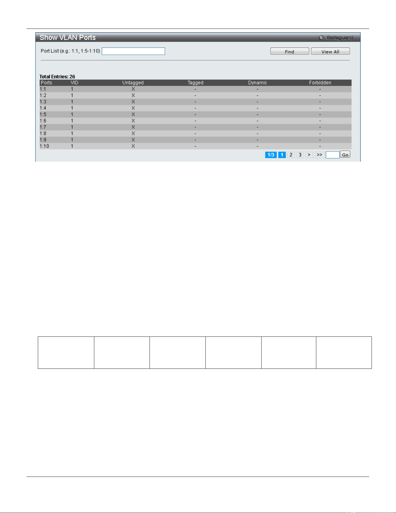
xStack® DGS-3420 Series Layer 2 Managed Stackable Gigabit Switch Web UI Reference Guide
101
Figure 4-27 Show VLAN Ports window
Click the View All button to display all the existing entries.
Enter a page number and click the Go button to navigate to a specific page when multiple pages exist.
QinQ
Q-in-Q VLANs allow network providers to expand their VLAN configurations to place customer VLANs within a larger
inclusive VLAN, which adds a new layer to the VLAN configuration. This basically lets large ISP's create L2 Virtual
Private Networks and also create transparent LANs for their customers, which will connect two or more customer LAN
points without over-complicating configurations on the client's side. Not only will over-complication be avoided, but also
now the administrator has over 4000 VLANs in which over 4000 VLANs can be placed, therefore greatly expanding the
VLAN network and enabling greater support of customers utilizing multiple VLANs on the network.
Q-in-Q VLANs are basically VLAN tags placed within existing IEEE 802.1Q VLANs which we will call SPVIDs (Service
Provider VLAN IDs). These VLANs are marked by a TPID (Tagged Protocol ID), configured in hex form to be
encapsulated within the VLAN tag of the packet. This identifies the packet as double-tagged and segregates it from
other VLANs on the network, therefore creating a hierarchy of VLANs within a single packet.
Here is an example Q-in-Q VLAN tagged packet.
Destination
Address
Source Address
SPVLAN (TPID
+ Service
Provider VLAN
Tag)
802.1Q CEVLAN
Tag (TPID +
Customer VLAN
Tag)
Ether Type Payload
Consider the example below:
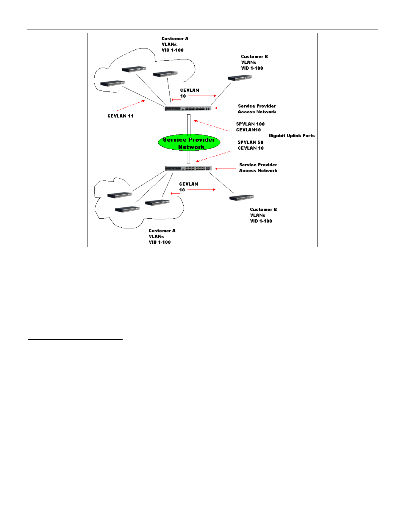
xStack® DGS-3420 Series Layer 2 Managed Stackable Gigabit Switch Web UI Reference Guide
102
Figure 4-28 QinQ example window
In this example, the Service Provider Access Network switch (Provider edge switch) is the device creating and
configuring Q-in-Q VLANs. Both CEVLANs (Customer VLANs), 10 and 11, are tagged with the SPVID 100 on the
Service Provider Access Network and therefore belong to one VLAN on the Service Provider’s network, thus being a
member of two VLANs. In this way, the Customer can retain its normal VLAN and the Service Provider can congregate
multiple Customer VLANs within one SPVLAN, thus greatly regulating traffic and routing on the Service Provider switch.
This information is then routed to the Service Provider’s main network and regarded there as one VLAN, with one set
of protocols and one routing behavior.
Regulations for Q-in-Q VLANs
1. Some rules and regulations apply with the implementation of the Q-in-Q VLAN procedure.
2. Ports can be configured as UNI ports or NNI ports. Both UNI and NNI ports can be configured as Gigabit ports.
3. Provider Edge switches must allow frames of at least 1522 bytes or more, due to the addition of the SPVID tag.
4. UNI ports can be an untagged or a tagged port of the service provider VLAN. NNI ports must be a tagged port
of the service provider VLANs.
5. The switch cannot have both double and normal VLANs co-existing. Once the change of VLAN is made, all
Access Control lists are cleared and must be reconfigured.
6. When Q-in-Q VLANs are enabled, GVRP can work with Q-in-Q VLANs.
7. The tags of all packets sent from the CPU to the UNI ports must be striped or replaced.
8. The following functions will not operate when the switch is in Q-in-Q VLAN mode:
• Guest VLANs.
• Web-based Access Control.
• IP Multicast Routing.
• All Regular 802.1Q VLAN functions.
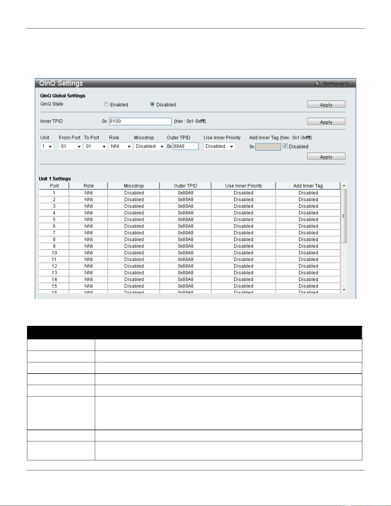
xStack® DGS-3420 Series Layer 2 Managed Stackable Gigabit Switch Web UI Reference Guide
103
QinQ Settings
The user can configure the Q-in-Q parameters in this page.
To view the following window, click L2 Features > QinQ > QinQ Settings, as show below:
Figure 4-29 QinQ Settings Window
The fields that can be configured are described below:
Parameter Description
QinQ State
Selecting this option enable the Q-in-Q feature.
Inner TPID
Enter an Inner TPID in customer VLAN tag here.
Unit
Select the unit you wish to configure.
From Port / To Port
Here the user can select a range of ports to use in the configuration.
Role
Port role in Q-in-Q mode, it can be UNI port or NNI port.
Missdrop
This option enables or disables C-VLAN based SP-VLAN assignment miss drop. If
Missdrop is enabled, the packet that does not match any assignment rule in the VLAN
translation and Q-in-Q profile, will be dropped. If disabled, then the packet will be forwarded
and will be assigned to the PVID of the received port.
Outer TPID
Enter an Outer TPID in SP-VLAN tag here.
Use Inner Priority
Use the drop-down menu to specify whether to use the priority in the C-VLAN tag as the
priority in the S-VLAN tag. By default, the setting is Disabled.
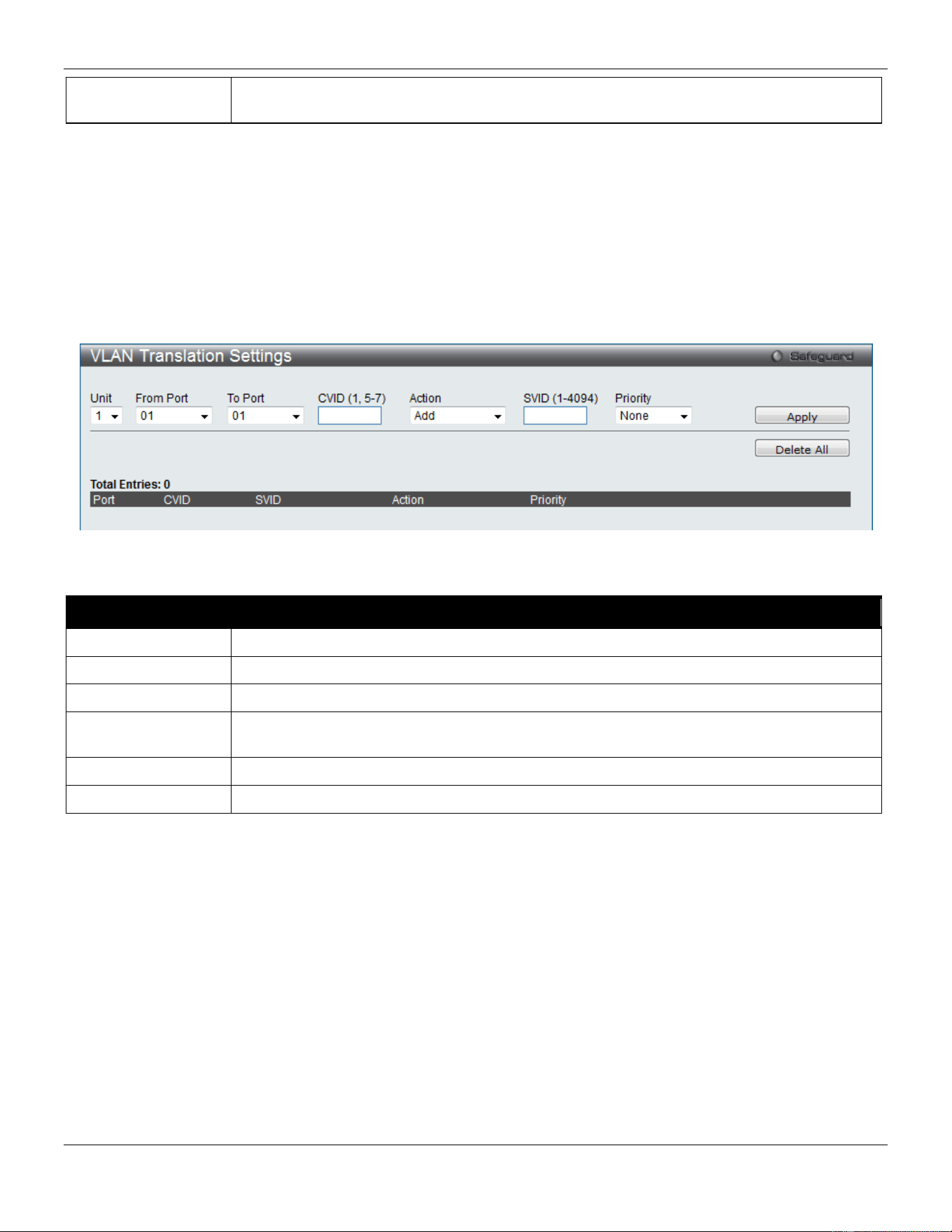
xStack® DGS-3420 Series Layer 2 Managed Stackable Gigabit Switch Web UI Reference Guide
104
Add Inner Tag Deselect the Disable check box and enter an entry that an Inner Tag will be added to the
entry. By default the Disabled check box is selected.
Click the Apply button to accept the changes made for each individual section.
VLAN Translation Settings
This page can be used to add translation relationship between C-VLAN and SP-VLAN. On ingress at UNI port, the C-
VLAN tagged packets will be translated to SP-VLAN tagged packets by adding or replacing according the configured
rule. On egress at this port, the SP-VLAN tag will be recovered to C-VLAN tag or be striped. The priority will be the
priority in the SP-VLAN tag if the inner priority flag is disabled for the receipt port.
To view the following window, click L2 Features > QinQ > VLAN Translation Settings, as show below:
Figure 4-30 VLAN Translation Settings Window
The fields that can be configured are described below:
Parameter Description
Unit
Select the unit you wish to configure.
From Port / To Port
Select a range of ports to use in the configuration.
CVID (1, 5-7)
Enter the C-VLAN ID to match.
Action
The action indicates to add an S-tag before a C-tag or to replace the original C-tag by an S-
tag.
SVID (1-4094)
Enter the SP-VLAN ID.
Priority
Select the priority of the s-tag.
Click the Apply button to accept the changes made for each individual section.
Click the Delete All button to remove all the entries listed.
Click the Edit button to re-configure the specific entry.
Click the Delete button to remove a specific entry.
Enter a page number and click the Go button to navigate to a specific page when multiple pages exist.
VLAN Translation Port Mapping Settings
Here the user can configure the VLAN translation port mapping settings.
To view the following window, click L2 Features > QinQ > VLAN Translation Port Mapping Settings, as show below:
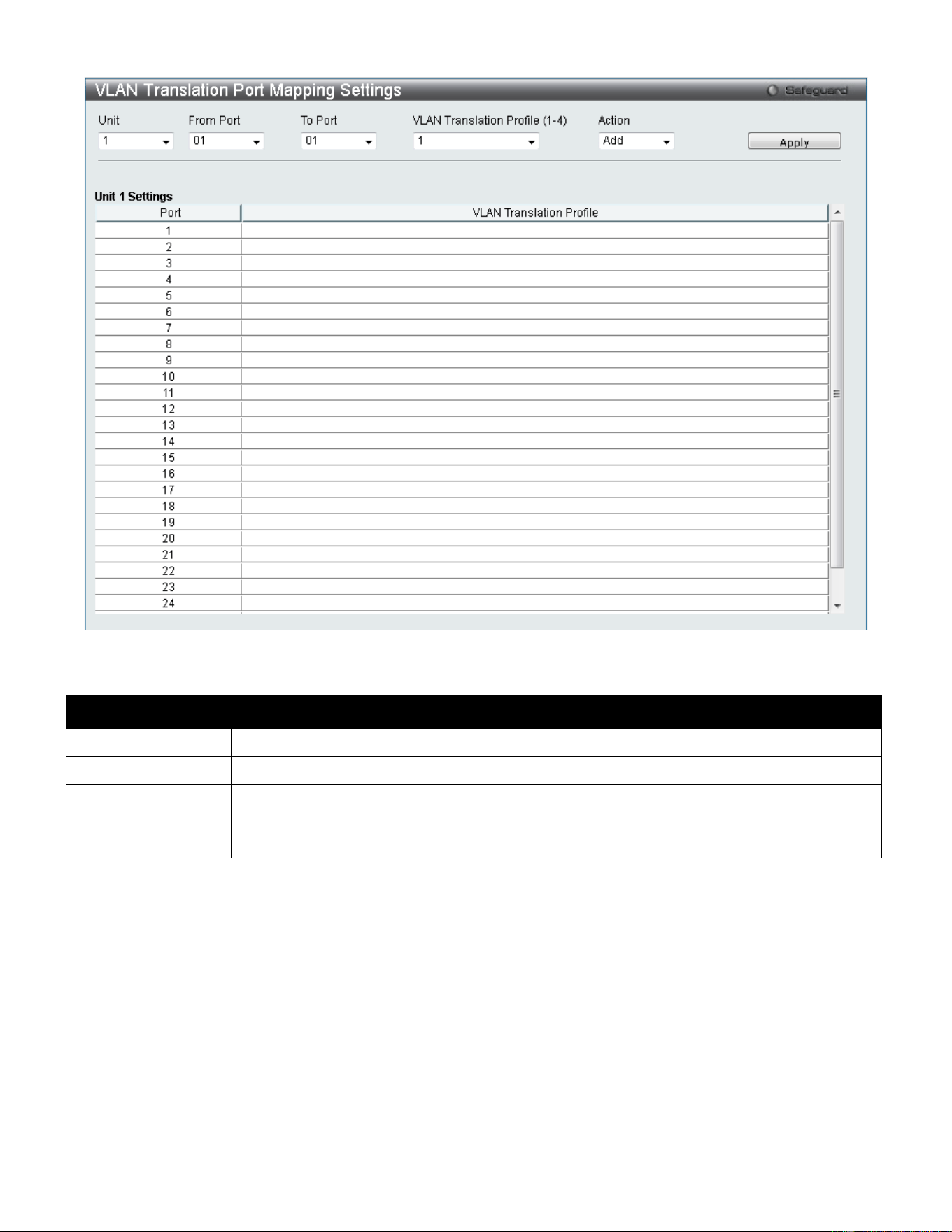
xStack® DGS-3420 Series Layer 2 Managed Stackable Gigabit Switch Web UI Reference Guide
105
Figure 4-31 VLAN Translation Port Mapping Settings window
The fields that can be configured are described below:
Parameter Description
Unit
Select the unit you wish to configure.
From Port / To Port
Select a range of ports to use in the configuration.
VLAN Translation
Profile (1-4)
Select the VLAN translation profile that will be configured here.
Action
The action indicates to add a VLAN translation profile to the ports selected.
Click the Apply button to accept the changes made for each individual section.
VLAN Translation Profile List
Here the user can configure the VLAN translation profile list.
To view the following window, click L2 Features > QinQ > VLAN Translation Profile List, as show below:
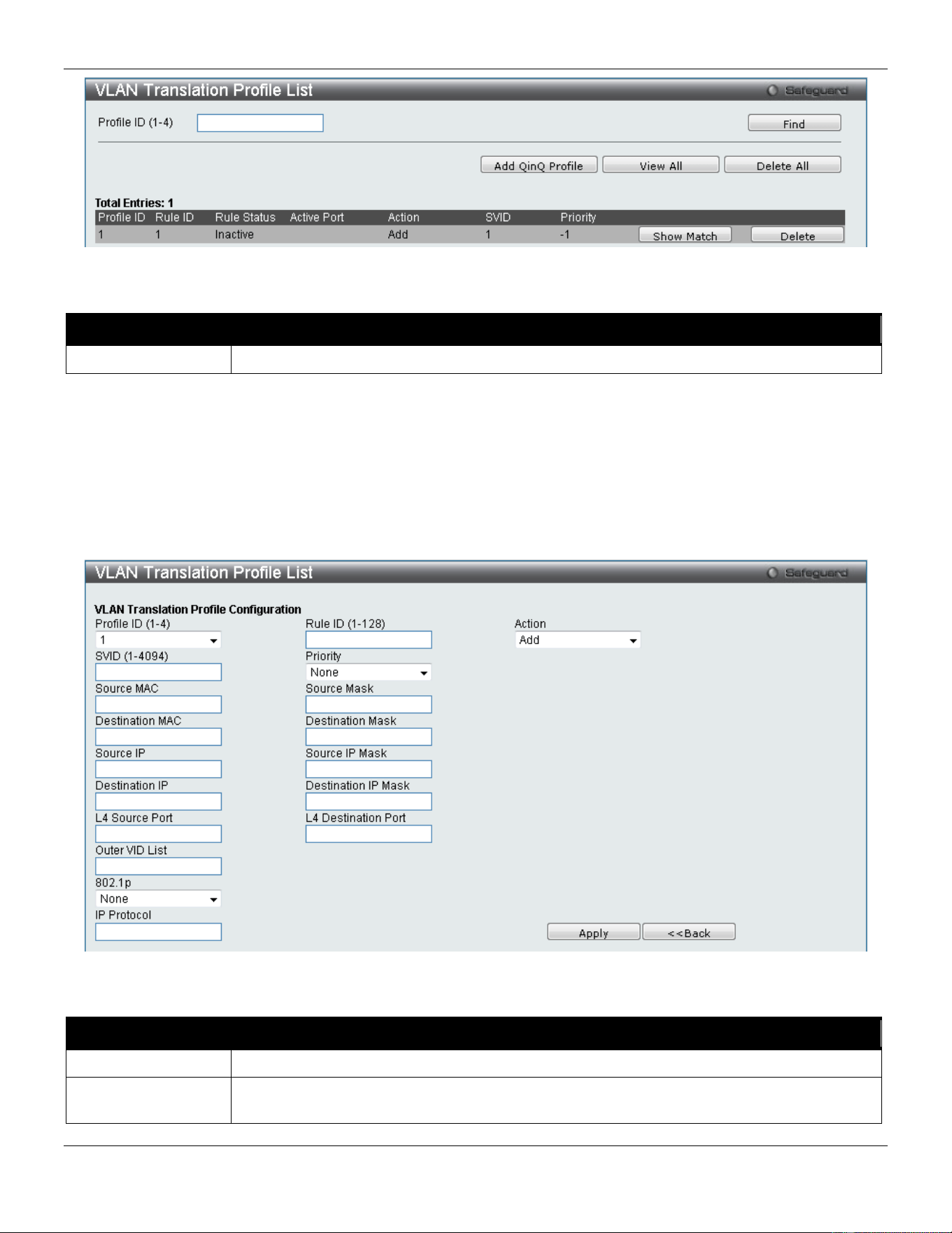
xStack® DGS-3420 Series Layer 2 Managed Stackable Gigabit Switch Web UI Reference Guide
106
Figure 4-32 VLAN Translation Profile List window
The fields that can be configured are described below:
Parameter Description
Profile ID (1-4)
Enter the VLAN translation profile ID used here.
Click the Find button to locate the profile entered.
Click the Add QinQ Profile button to add a QinQ profile to the VLAN translation profile list.
Click the View All button to view all the configured profiles.
Click the Delete All button to delete all configured profiles.
Click the Show Match button to view the QinQ VLAN Translation Rule Information.
Click the Delete button to remove the specific entry.
After clicking the Add QinQ Profile button, the following page will be available:
Figure 4-33 VLAN Translation Profile List window (Add QinQ Profile)
The fields that can be configured are described below:
Parameter Description
Profile ID (1-4)
Select the profile ID to configure
Rule ID (1-128)
Enter the rule ID to be added to the profile. If the rule ID is not specified, it will be assigned
automatically.
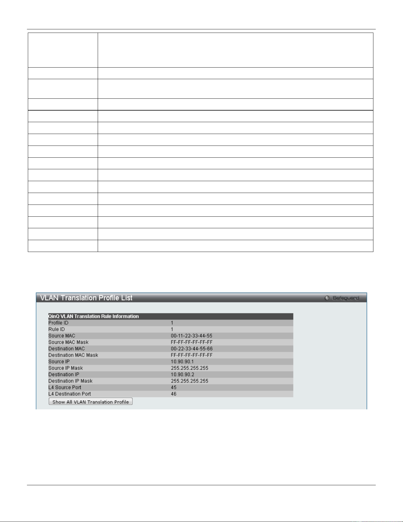
xStack® DGS-3420 Series Layer 2 Managed Stackable Gigabit Switch Web UI Reference Guide
107
Action Select the action that will be taken here. Options to choose from are Add and Replace. Add
specifies to add a tag for the assigned S-VLAN before the Outer-VLAN tag. If there is an S-
TAG in the packet, this rule will not take effect. Replace specifies to replace the outer-VLAN
ID in the tag by the SVID. If there is no TAG in the packet, this rule will not take effect.
SVID (1-4094)
Enter the S-VLAN ID to be assigned to the matched packet.
Priority
Select the 802.1p priority of the S-Tag. If the priority is not specified, the 802.1p priority of
S-Tag will be assigned by the default procedure.
Source MAC
Enter the source MAC address or MAC address range for the match.
Source Mask
Enter the source MAC address mask.
Destination MAC
Enter the destination MAC address or MAC address range for the match.
Destination Mask
Enter the destination MAC address mask.
Source IP
Enter the source IPv4 address or IPv4 subnet for the match.
Source IP Mask
Enter the source IPv4 address mask used.
Destination IP
Enter the destination IPv4 address or IPv4 subnet for the match.
Destination IP Mask
Enter the destination IPv4 address mask used.
L4 Source Port
Enter the Layer 4 source port ID for the match.
L4 Destination Port
Enter the Layer 4 destination port ID for the match.
Outer VID List
Enter the packet’s outer-VID for the match.
802.1p
Select the packet’s 802.1p priority for the match.
IP Protocol
Enter the IP protocol number used. This value must be between 0 and 255.
Click the Apply button to accept the changes made.
Click the <<Back button to discard the changes and return to the previous page.
After clicking the Show Match button, the following page will be available:
Figure 4-34 VLAN Translation Profile List window (Show Match)
Click the Show All VLAN Translation Profile button to the return to the main page.
Layer 2 Protocol Tunneling Settings
This window is used to configure the layer 2 Protocol tunneling port settings.
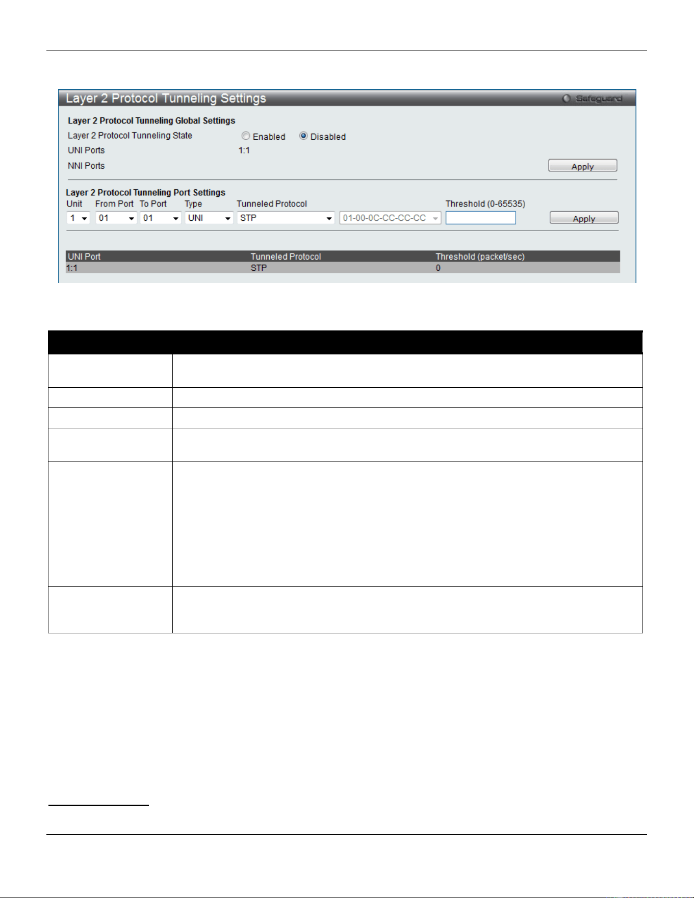
xStack® DGS-3420 Series Layer 2 Managed Stackable Gigabit Switch Web UI Reference Guide
108
To view the following window, click L2 Features > Layer 2 Protocol Tunneling Settings, as show below:
Figure 4-35 Layer 2 Protocol Tunneling Settings window
The fields that can be configured are described below:
Parameter Description
Layer 2 protocol
tunneling State
Use the radio buttons to enable or disable the layer 2 protocol tunneling function globally
on the Switch.
Unit
Select the unit you wish to configure.
From Port / To Port
Select a range of ports to use in the configuration.
Type Use the drop-down menu to select the type of the ports. Available choices are UNI, NNI
and None. The default type is None.
Tunneled Protocol When UNI is selected in the Type drop-down menu, this drop-down menu shows the
following options:
STP- Specify the BPDU received on these UNI will be tunneled.
GVRP - Specify the GVRP PDU received on these UNI will be tunneled.
Protocol MAC - Specify the destination MAC address of the L2 protocol packets that will
tunneled on these UNI ports. At present, the MAC address can be 01-00-0C-CC-CC-CC or
01-00-0C-CC-CC-CD.
All - Specify all supported.
Threshold (0-65535)
Enter the drop threshold for packets-per-second accepted on this UNI port. The port drops
the PDU if the protocol’s threshold is exceeded. The range of the threshold value is 0 to
65535 (packet/second). The value 0 means unlimited. By default, the value is 0.
Click the Apply button to accept the changes made for each individual section.
Spanning Tree
This Switch supports three versions of the Spanning Tree Protocol: 802.1D-1998 STP, 802.1D-2004 Rapid STP, and
802.1Q-2005 MSTP. 802.1D-1998 STP will be familiar to most networking professionals. However, since 802.1D-2004
RSTP and 802.1Q-2005 MSTP have been recently introduced to D-Link managed Ethernet switches, a brief
introduction to the technology is provided below followed by a description of how to set up 802.1D-1998 STP, 802.1D-
2004 RSTP, and 802.1Q-2005 MSTP.
802.1Q-2005 MSTP

xStack® DGS-3420 Series Layer 2 Managed Stackable Gigabit Switch Web UI Reference Guide
109
Multiple Spanning Tree Protocol, or MSTP, is a standard defined by the IEEE community that allows multiple VLANs to
be mapped to a single spanning tree instance, which will provide multiple pathways across the network. Therefore,
these MSTP configurations will balance the traffic load, preventing wide scale disruptions when a single spanning tree
instance fails. This will allow for faster convergences of new topologies for the failed instance. Frames designated for
these VLANs will be processed quickly and completely throughout interconnected bridges utilizing any of the three
spanning tree protocols (STP, RSTP or MSTP).
This protocol will also tag BPDU packets so receiving devices can distinguish spanning tree instances, spanning tree
regions and the VLANs associated with them. An MSTI ID will classify these instances. MSTP will connect multiple
spanning trees with a Common and Internal Spanning Tree (CIST). The CIST will automatically determine each MSTP
region, its maximum possible extent and will appear as one virtual bridge that runs a single spanning tree.
Consequentially, frames assigned to different VLANs will follow different data routes within administratively established
regions on the network, continuing to allow simple and full processing of frames, regardless of administrative errors in
defining VLANs and their respective spanning trees.
Each switch utilizing the MSTP on a network will have a single MSTP configuration that will have the following three
attributes:
1. A configuration name defined by an alphanumeric string of up to 32 characters (defined in the MST
Configuration Identification window in the Configuration Name field).
2. A configuration revision number (named here as a Revision Level and found in the MST Configuration
Identification window) and;
3. A 4094-element table (defined here as a VID List in the MST Configuration Identification window), which will
associate each of the possible 4094 VLANs supported by the Switch for a given instance.
To utilize the MSTP function on the Switch, three steps need to be taken:
1. The Switch must be set to the MSTP setting (found in the STP Bridge Global Settings window in the STP
Version field)
2. The correct spanning tree priority for the MSTP instance must be entered (defined here as a Priority in the
MSTI Config Information window when configuring MSTI ID settings).
3. VLANs that will be shared must be added to the MSTP Instance ID (defined here as a VID List in the MST
Configuration Identification window when configuring an MSTI ID settings).
802.1D-2004 Rapid Spanning Tree
The Switch implements three versions of the Spanning Tree Protocol, the Multiple Spanning Tree Protocol (MSTP) as
defined by the IEEE 802.1Q-2005, the Rapid Spanning Tree Protocol (RSTP) as defined by the IEEE 802.1D-2004
specification and a version compatible with the IEEE 802.1D-1998 STP. RSTP can operate with legacy equipment
implementing IEEE 802.1D-1998; however the advantages of using RSTP will be lost.
The IEEE 802.1D-2004 Rapid Spanning Tree Protocol (RSTP) evolved from the 802.1D-1998 STP standard. RSTP
was developed in order to overcome some limitations of STP that impede the function of some recent switching
innovations, in particular, certain Layer 3 functions that are increasingly handled by Ethernet switches. The basic
function and much of the terminology is the same as STP. Most of the settings configured for STP are also used for
RSTP. This section introduces some new Spanning Tree concepts and illustrates the main differences between the
two protocols.
Port Transition States
An essential difference between the three protocols is in the way ports transition to a forwarding state and in the way
this transition relates to the role of the port (forwarding or not forwarding) in the topology. MSTP and RSTP combine
the transition states disabled, blocking and listening used in 802.1D-1998 and creates a single state Discarding. In
either case, ports do not forward packets. In the STP port transition states disabled, blocking or listening or in the
RSTP/MSTP port state discarding, there is no functional difference, the port is not active in the network topology. Table
7-3 below compares how the three protocols differ regarding the port state transition.
xStack® DGS-3420 Series Layer 2 Managed Stackable Gigabit Switch Web UI Reference Guide
110
All three protocols calculate a stable topology in the same way. Every segment will have a single path to the root
bridge. All bridges listen for BPDU packets. However, BPDU packets are sent more frequently - with every Hello packet.
BPDU packets are sent even if a BPDU packet was not received. Therefore, each link between bridges is sensitive to
the status of the link. Ultimately this difference results in faster detection of failed links, and thus faster topology
adjustment. A drawback of 802.1D-1998 is this absence of immediate feedback from adjacent bridges.
802.1Q-2005 MSTP 802.1D-2004 RSTP 802.1D-1998 STP Forwarding Learning
Disabled
Disabled
Disabled
No
No
Discarding
Discarding
Blocking
No
No
Discarding
Discarding
Listening
No
No
Learning
Learning
Learning
No
Yes
Forwarding
Forwarding
Forwarding
Yes
Yes
RSTP is capable of a more rapid transition to a forwarding state - it no longer relies on timer configurations - RSTP
compliant bridges are sensitive to feedback from other RSTP compliant bridge links. Ports do not need to wait for the
topology to stabilize before transitioning to a forwarding state. In order to allow this rapid transition, the protocol
introduces two new variables: the edge port and the point-to-point (P2P) port.
Edge Port
The edge port is a configurable designation used for a port that is directly connected to a segment where a loop cannot
be created. An example would be a port connected directly to a single workstation. Ports that are designated as edge
ports transition to a forwarding state immediately without going through the listening and learning states. An edge port
loses its status if it receives a BPDU packet, immediately becoming a normal spanning tree port.
P2P Port
A P2P port is also capable of rapid transition. P2P ports may be used to connect to other bridges. Under RSTP/MSTP,
all ports operating in full-duplex mode are considered to be P2P ports, unless manually overridden through
configuration.
802.1D-1998/802.1D-2004/802.1Q-2005 Compatibility
MSTP or RSTP can interoperate with legacy equipment and is capable of automatically adjusting BPDU packets to
802.1D-1998 format when necessary. However, any segment using 802.1D-1998 STP will not benefit from the rapid
transition and rapid topology change detection of MSTP or RSTP. The protocol also provides for a variable used for
migration in the event that legacy equipment on a segment is updated to use RSTP or MSTP.
The Spanning Tree Protocol (STP) operates on two levels:
1. On the switch level, the settings are globally implemented.
2. On the port level, the settings are implemented on a per-user-defined group of ports basis.
STP Bridge Global Settings
On this page the user can configure the STP bridge global parameters.
To view the following window, click L2 Features > Spanning Tree > STP Bridge Global Settings, as show below:
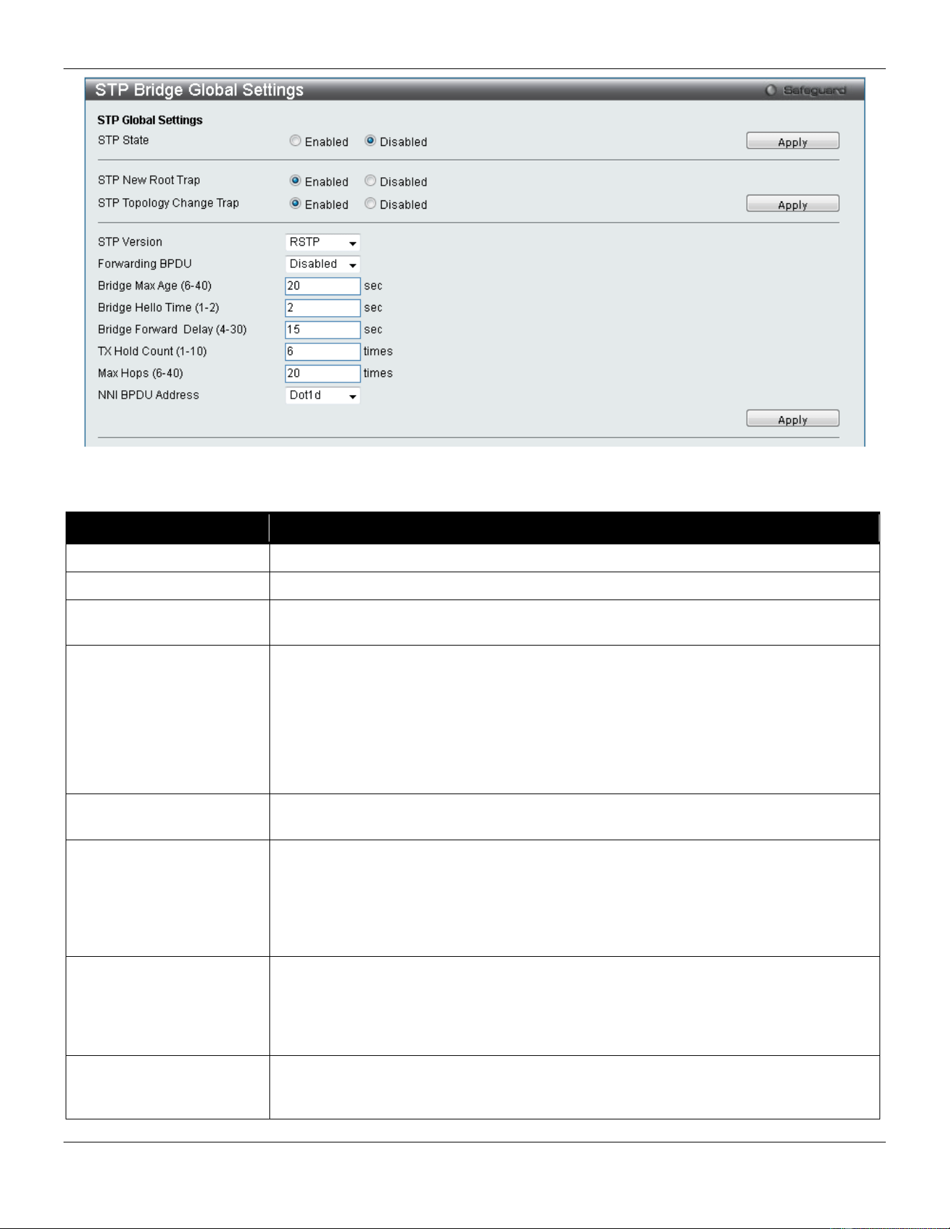
xStack® DGS-3420 Series Layer 2 Managed Stackable Gigabit Switch Web UI Reference Guide
111
Figure 4-36 STP Bridge Global Settings window
The fields that can be configured are described below:
Parameter Description
STP Status
Use the radio button to globally enable or disable STP.
STP New Root Trap
Click to enable or disable sending new root traps.
STP Topology Change
Trap
Click to enable or disable sending topology change traps.
STP Version
Use the drop-down menu to choose the desired version of STP:
STP - Select this parameter to set the Spanning Tree Protocol (STP) globally on the
switch.
RSTP - Select this parameter to set the Rapid Spanning Tree Protocol (RSTP)
globally on the Switch.
MSTP - Select this parameter to set the Multiple Spanning Tree Protocol (MSTP)
globally on the Switch.
Forwarding BPDU This field can be Enabled or Disabled. When Enabled, it allows the forwarding of STP
BPDU packets from other network devices. The default is Disabled.
Bridge Max Age (6-40)
The Max Age may be set to ensure that old information does not endlessly circulate
through redundant paths in the network, preventing the effective propagation of the
new information. Set by the Root Bridge, this value will aid in determining that the
Switch has spanning tree configuration values consistent with other devices on the
bridged LAN. The user may choose a time between 6 and 40 seconds. The default
value is 20 seconds.
Bridge Hello Time (1-2) The Hello Time can be set from 1 to 2 seconds. This is the interval between two
transmissions of BPDU packets sent by the Root Bridge to tell all other switches that it
is indeed the Root Bridge. This field will only appear here when STP or RSTP is
selected for the STP Version. For MSTP, the Hello Time must be set on a port per
port basis. The default is 2 seconds.
Bridge Forward Delay (4-
30)
The Forward Delay can be from 4 to 30 seconds. Any port on the Switch spends this
time in the listening state while moving from the blocking state to the forwarding state.
The default is 15 seconds
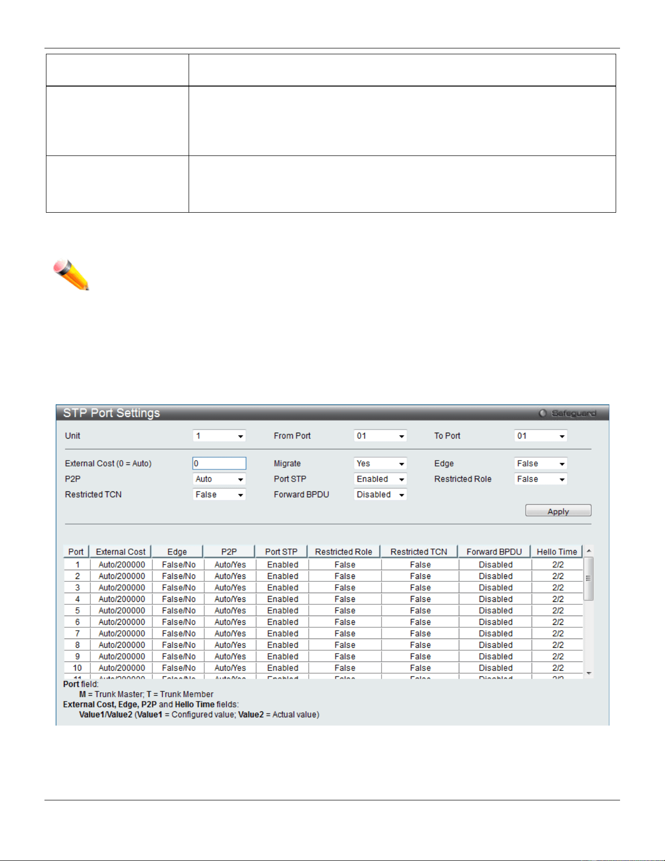
xStack® DGS-3420 Series Layer 2 Managed Stackable Gigabit Switch Web UI Reference Guide
112
Tx Hold Count (1-10)
Used to set the maximum number of Hello packets transmitted per interval. The count
can be specified from 1 to 10. The default is 6.
Max Hops (6-40)
Used to set the number of hops between devices in a spanning tree region before the
BPDU (bridge protocol data unit) packet sent by the Switch will be discarded. Each
switch on the hop count will reduce the hop count by one until the value reaches zero.
The Switch will then discard the BDPU packet and the information held for the port will
age out. The user may set a hop count from 6 to 40. The default is 20.
NNI BPDU Address
Used to determine the BPDU protocol address for GVRP in service provide site. It can
use 802.1d GVRP address, 802.1ad service provider GVRP address or a user defined
multicast address. The range of the user defined address is 0180C2000000 -
0180C2FFFFFF.
Click the Apply button to accept the changes made for each individual section.
NOTE: The Bridge Hello Time cannot be longer than the Bridge Max Age. Otherwise, a configuration
error will occur. Observe the following formulas when setting the above parameters:
Bridge Max Age <= 2 x (Bridge Forward Delay - 1 second)
Bridge Max Age > 2 x (Bridge Hello Time + 1 second)
STP Port Settings
STP can be set up on a port per port basis.
To view the following window, click L2 Features > Spanning Tree > STP Port Settings, as show below:
Figure 4-37 STP Port Settings window
It is advisable to define an STP Group to correspond to a VLAN group of ports.

xStack® DGS-3420 Series Layer 2 Managed Stackable Gigabit Switch Web UI Reference Guide
113
The fields that can be configured are described below:
Parameter Description
Unit
Select the unit you wish to configure.
From Port / To Port
Select the starting and ending ports to be configured.
External Cost
(0 = Auto)
This defines a metric that indicates the relative cost of forwarding packets to the
specified port list. Port cost can be set automatically or as a metric value. The default
value is 0 (auto). Setting 0 for the external cost will automatically set the speed for
forwarding packets to the specified port(s) in the list for optimal efficiency. The default
port cost for a 100Mbps port is 200000 and the default port cost for a Gigabit port is
20000. Enter a value between 1 and 200000000 to determine the External Cost. The
lower the number, the greater the probability the port will be chosen to forward packets.
P2P Choosing the True parameter indicates a point-to-point (P2P) shared link. P2P ports are
similar to edge ports; however they are restricted in that a P2P port must operate in full
duplex. Like edge ports, P2P ports transition to a forwarding state rapidly thus benefiting
from RSTP. A P2P value of False indicates that the port cannot have P2P status. Auto
allows the port to have P2P status whenever possible and operate as if the P2P status
were True. If the port cannot maintain this status, (for example if the port is forced to
half-duplex operation) the P2P status changes to operate as if the P2P value were
False. The default setting for this parameter is Auto.
Restricted TCN
Topology Change Notification is a simple BPDU that a bridge sends out to its root port to
signal a topology change. Restricted TCN can be toggled between True and False. If set
to True, this stops the port from propagating received topology change notifications and
topology changes to other ports. The default is False.
Migrate When operating in RSTP mode, selecting Yes forces the port that has been selected to
transmit RSTP BPDUs.
Port STP
This drop-down menu allows you to enable or disable STP for the selected group of
ports. The default is Enabled.
Forward BPDU
Use the drop-down menu to enable or disable the flooding of BPDU packets when STP
is disabled.
Edge Choosing the True parameter designates the port as an edge port. Edge ports cannot
create loops, however an edge port can lose edge port status if a topology change
creates a potential for a loop. An edge port normally should not receive BPDU packets. If
a BPDU packet is received, it automatically loses edge port status. Choosing the False
parameter indicates that the port does not have edge port status. Alternatively, the Auto
option is available.
Restricted Role Use the drop-down menu to toggle Restricted Role between True and False. If set to
True, the port will never be selected to be the Root port. The default is False.
Click the Apply button to accept the changes made.
MST Configuration Identification
This window allows the user to configure a MSTI instance on the Switch. These settings will uniquely identify a multiple
spanning tree instance set on the Switch. The Switch initially possesses one CIST, or Common Internal Spanning Tree,
of which the user may modify the parameters for but cannot change the MSTI ID for, and cannot be deleted.
To view the following window, click L2 Features > Spanning Tree > MST Configuration Identification, as show
below:
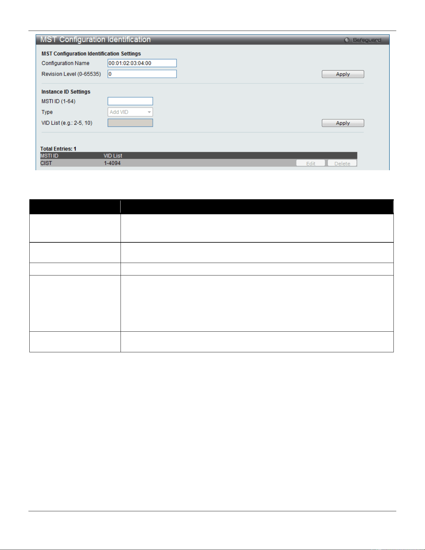
xStack® DGS-3420 Series Layer 2 Managed Stackable Gigabit Switch Web UI Reference Guide
114
Figure 4-38 MST Configuration Identification window
The fields that can be configured are described below:
Parameter Description
Configuration Name
This name uniquely identifies the MSTI (Multiple Spanning Tree Instance). If a
Configuration Name is not set, this field will show the MAC address to the device
running MSTP.
Revision Level
(0-65535)
This value, along with the Configuration Name, identifies the MSTP region configured
on the Switch.
MSTI ID (1-64)
Enter a number between 1 and 64 to set a new MSTI on the Switch.
Type
This field allows the user to choose a desired method for altering the MSTI settings.
The user has two choices:
Add VID - Select this parameter to add VIDs to the MSTI ID, in conjunction with the
VID List parameter.
Remove VID - Select this parameter to remove VIDs from the MSTI ID, in conjunction
with the VID List parameter.
VID List (e.g.: 2-5, 10)
This field is used to specify the VID range from configured VLANs set on the Switch.
Supported VIDs on the Switch range from ID number 1 to 4094.
Click the Apply button to accept the changes made for each individual section.
Click the Edit button to re-configure the specific entry.
Click the Delete button to remove the specific entry.
STP Instance Settings
This window displays MSTIs currently set on the Switch and allows users to change the Priority of the MSTIs.
To view the following window, click L2 Features > Spanning Tree > STP Instance Settings, as show below:
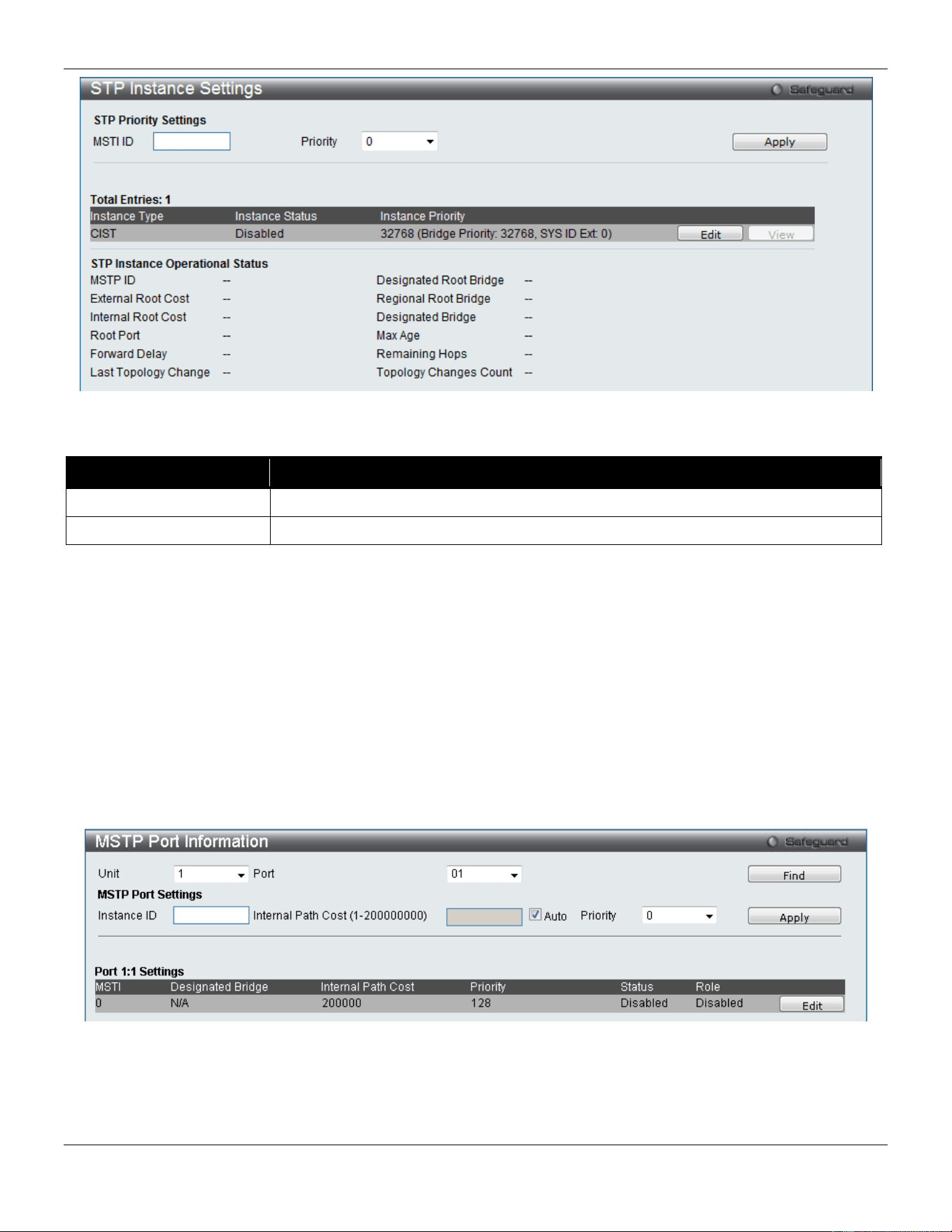
xStack® DGS-3420 Series Layer 2 Managed Stackable Gigabit Switch Web UI Reference Guide
115
Figure 4-39STP Instance Settings window
The fields that can be configured are described below:
Parameter Description
MSTI ID
Enter the MSTI ID in this field. An entry of 0 denotes the CIST (default MSTI).
Priority
Enter the priority in this field. The available range of values is from 0 to 61440.
Click the Apply button to accept the changes made.
Click the Edit button to re-configure the specific entry.
Click the View button to display the information of the specific entry.
MSTP Port Information
This window displays the current MSTI configuration information and can be used to update the port configuration for
an MSTI ID. If a loop occurs, the MSTP function will use the port priority to select an interface to put into the forwarding
state. Set a higher priority value for interfaces to be selected for forwarding first. In instances where the priority value is
identical, the MSTP function will implement the lowest MAC address into the forwarding state and other interfaces will
be blocked. Remember that lower priority values mean higher priorities for forwarding packets.
To view the following window, click L2 Features > Spanning Tree > MSTP Port Information, as show below:
Figure 4-40 MSTP Port Information window
To view the MSTI settings for a particular port, use the drop-down menu to select the Port number. To modify the
settings for a particular MSTI instance, enter a value in the Instance ID field, an Internal Path Cost, and use the drop-
down menu to select a Priority.
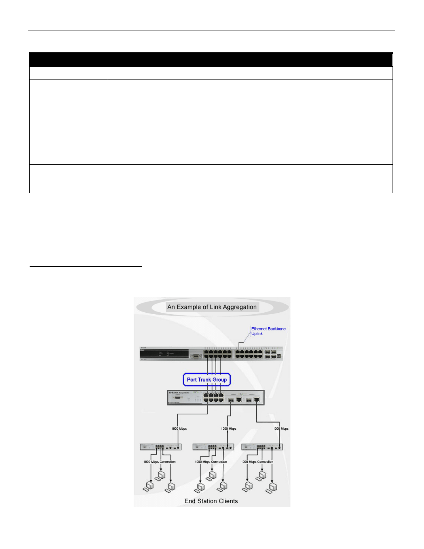
xStack® DGS-3420 Series Layer 2 Managed Stackable Gigabit Switch Web UI Reference Guide
116
The fields that can be configured are described below:
Parameter Description
Unit
Select the unit you wish to configure.
Port
Select the port you want to configure.
Instance ID The MSTI ID of the instance to be configured. Enter a value between 0 and 64. An entry
of 0 in this field denotes the CIST (default MSTI).
Internal Path Cost (1-
200000000)
This parameter is set to represent the relative cost of forwarding packets to specified ports
when an interface is selected within an STP instance. Selecting this parameter with a
value in the range of 1 to 200000000 will set the quickest route when a loop occurs. A
lower Internal cost represents a quicker transmission. Selecting 0 (zero) for this parameter
will set the quickest route automatically and optimally for an interface. Tick the Auto
option to allow the system to assign a value here.
Priority Enter a value between 0 and 240 to set the priority for the port interface. A higher priority
will designate the interface to forward packets first. A lower number denotes a higher pri-
ority.
Click the Find button to locate a specific entry based on the information entered.
Click the Apply button to accept the changes made.
Click the Edit button to re-configure the specific entry.
Link Aggregation
Understanding Port Trunk Groups
Port trunk groups are used to combine a number of ports together to make a single high-bandwidth data pipeline. The
Switch supports up to 32 port trunk groups with two to eight ports in each group.

xStack® DGS-3420 Series Layer 2 Managed Stackable Gigabit Switch Web UI Reference Guide
117
4-41 Example of Port Trunk Group
The Switch treats all ports in a trunk group as a single port. Data transmitted to a specific host (destination address)
will always be transmitted over the same port in a trunk group. This allows packets in a data stream to arrive in the
same order they were sent.
Link aggregation allows several ports to be grouped together and to act as a single link. This gives a bandwidth that is
a multiple of a single link's bandwidth.
Link aggregation is most commonly used to link a bandwidth intensive network device or devices, such as a server, to
the backbone of a network.
The Switch allows the creation of up to 32 link aggregation groups, each group consisting of 2 to 8 links (ports). Each
port can only belong to a single link aggregation group.
All of the ports in the group must be members of the same VLAN, and their STP status, static multicast, traffic control;
traffic segmentation and 802.1p default priority configurations must be identical. Port locking and 802.1X must not be
enabled on the trunk group. Further, the LACP aggregated links must all be of the same speed and should be
configured as full duplex.
The Master Port of the group is to be configured by the user, and all configuration options, including the VLAN
configuration that can be applied to the Master Port, are applied to the entire link aggregation group.
Load balancing is automatically applied to the ports in the aggregated group, and a link failure within the group causes
the network traffic to be directed to the remaining links in the group.
The Spanning Tree Protocol will treat a link aggregation group as a single link, on the switch level. On the port level,
the STP will use the port parameters of the Master Port in the calculation of port cost and in determining the state of
the link aggregation group. If two redundant link aggregation groups are configured on the Switch, STP will block one
entire group; in the same way STP will block a single port that has a redundant link.
NOTE: If any ports within the trunk group become disconnected, packets intended for the disconnected
port will be load shared among the other linked ports of the link aggregation group.
Port Trunking Settings
On this page the user can configure the port trunk settings for the switch.
To view the following window, click L2 Features > Link Aggregation > Port Trunking Settings, as show below:
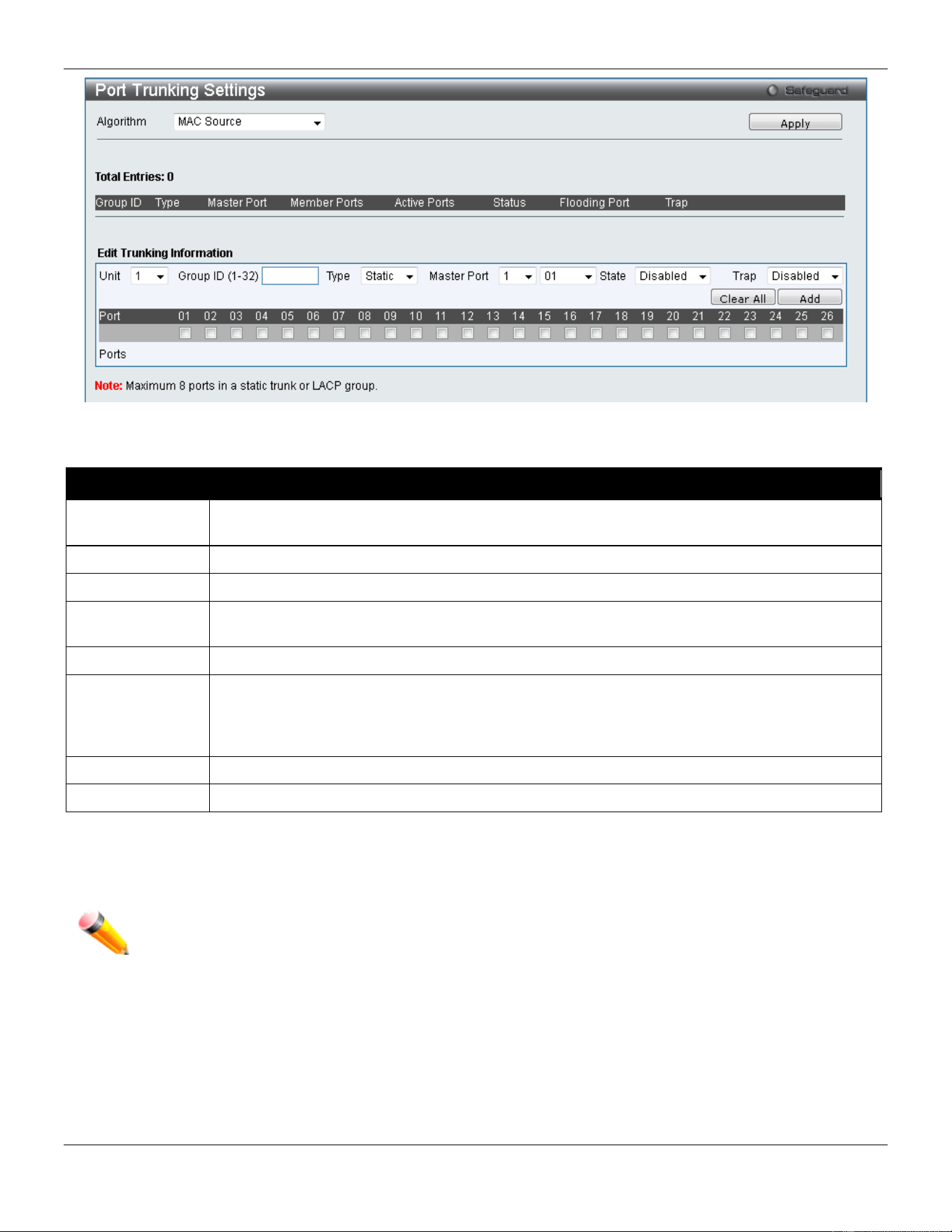
xStack® DGS-3420 Series Layer 2 Managed Stackable Gigabit Switch Web UI Reference Guide
118
Figure 4-42 Port Trunking Settings window
The fields that can be configured or displayed are described below:
Parameter Description
Algorithm
This is the traffic hash algorithm among the ports of the link aggregation group. Options to
choose from are MAC Source Dest, IP Source Dest and Lay4 Source Dest.
Unit
Select the unit you wish to configure.
Group ID (1-32)
Select an ID number for the group, between 1 and 32.
Type This drop-down menu allows users to select between Static and LACP (Link Aggregation
Control Protocol). LACP allows for the automatic detection of links in a Port Trunking Group.
Master Port
Choose the Master Port for the trunk group using the drop-down menu.
State Use the drop-down menu to toggle between Enabled and Disabled. This is used to turn a port
trunking group on or off. This is useful for diagnostics, to quickly isolate a bandwidth intensive
network device or to have an absolute backup aggregation group that is not under automatic
control.
Member Ports
Choose the members of a trunked group. Up to eight ports can be assigned to a group.
Active Ports
Shows the ports that are currently forwarding packets.
Click the Apply button to accept the changes made.
Click the Clear All button to clear out all the information entered.
Click the Add button to add a new entry based on the information entered.
NOTE: The maximum number of ports that can be configured in one Static Trunk or LACP Group are 8
ports.
LACP Port Settings
In conjunction with the Trunking window, users can create port trunking groups on the Switch. Using the following
window, the user may set which ports will be active and passive in processing and sending LACP control frames.
To view the following window, click L2 Features > Link Aggregation > LACP Port Settings, as show below:
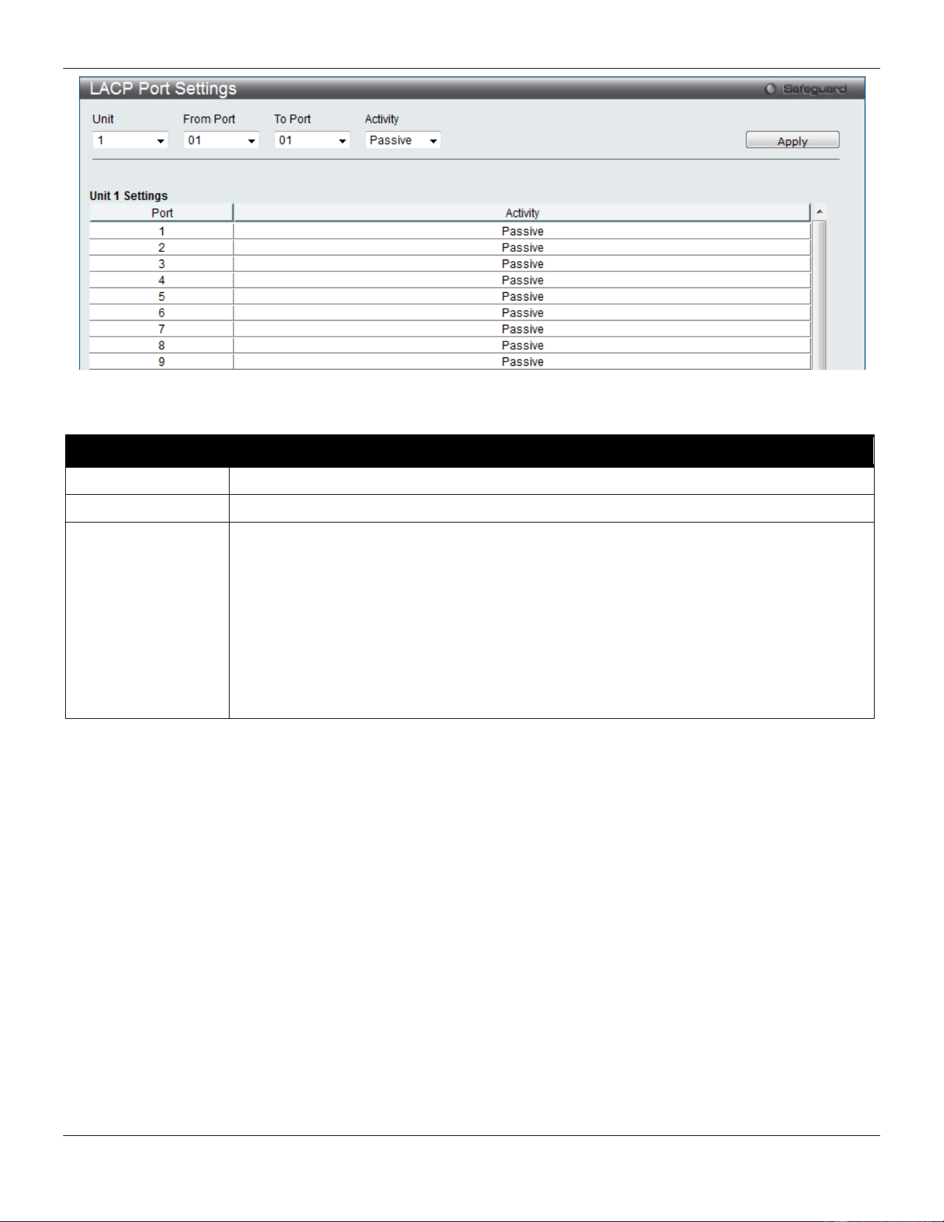
xStack® DGS-3420 Series Layer 2 Managed Stackable Gigabit Switch Web UI Reference Guide
119
Figure 4-43 LACP Port Settings window
The fields that can be configured are described below:
Parameter Description
Unit
Select the unit you wish to configure.
From Port / To Port
A consecutive group of ports may be configured starting with the selected port.
Activity Active - Active LACP ports are capable of processing and sending LACP control frames.
This allows LACP compliant devices to negotiate the aggregated link so the group may be
changed dynamically as needs require. In order to utilize the ability to change an
aggregated port group, that is, to add or subtract ports from the group, at least one of the
participating devices must designate LACP ports as active. Both devices must support
LACP.
Passive - LACP ports that are designated as passive cannot initially send LACP control
frames. In order to allow the linked port group to negotiate adjustments and make changes
dynamically, one end of the connection must have "active" LACP ports (see above).
Click the Apply button to accept the changes made.
FDB
Static FDB Settings
Unicast Static FDB Settings
This window is used to configure the static unicast forwarding on the Switch.
To view the following window, click L2 Features > FDB > Static FDB Settings > Unicast Static FDB Settings, as
show below:
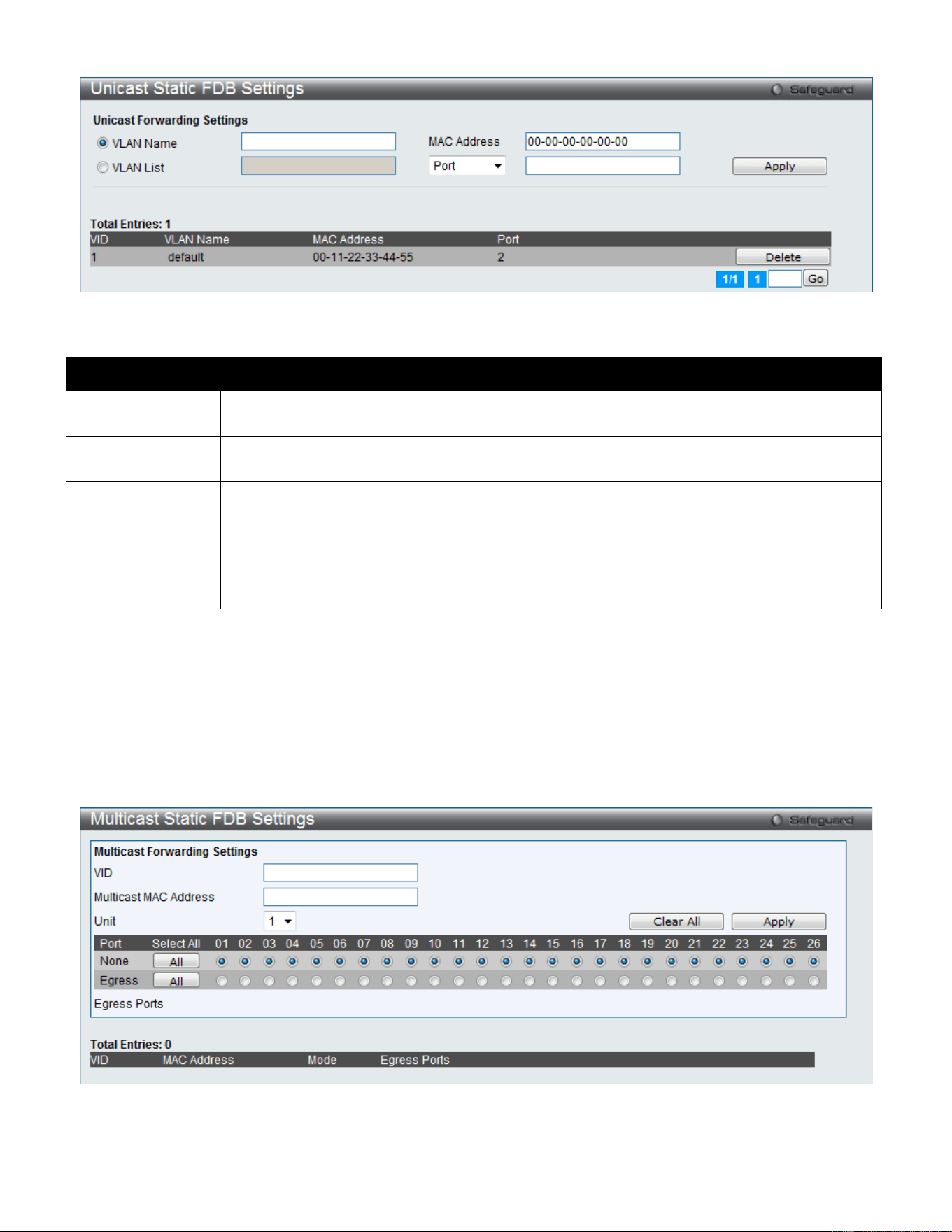
xStack® DGS-3420 Series Layer 2 Managed Stackable Gigabit Switch Web UI Reference Guide
120
Figure 4-44 Unicast Static FDB Settings window
The fields that can be configured are described below:
Parameter Description
VLAN Name
Click the radio button and enter the VLAN name of the VLAN on which the associated unicast
MAC address resides.
VLAN List
Click the radio button and enter a list of VLAN on which the associated unicast MAC address
resides.
MAC Address
The MAC address to which packets will be statically forwarded. This must be a unicast MAC
address.
Port/Drop
Allows the selection of the port number on which the MAC address entered above resides
This option could also drop the MAC address from the unicast static FDB. When selecting
Port, enter the port number in the field. The format can be "unit ID:port number" (e.g. 1:5) or
"port number" (e.g. 5). When only entering port number, the default unit ID is 1.
Click the Apply button to accept the changes made.
Click the Delete button to remove the specific entry.
Multicast Static FDB Settings
Users can set up static multicast forwarding on the Switch.
To view the following window, click L2 Features > FDB > Static FDB Settings > Multicast Static FDB Settings, as
show below:
Figure 4-45 Multicast Static FDB Settings window
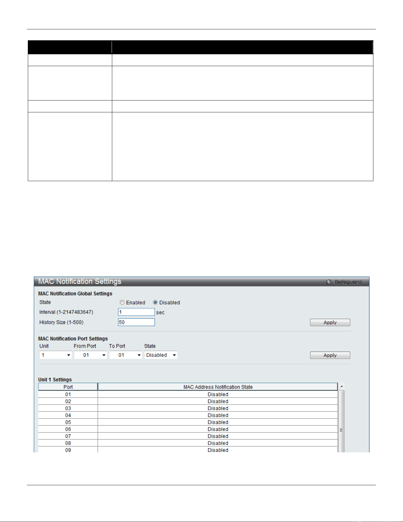
xStack® DGS-3420 Series Layer 2 Managed Stackable Gigabit Switch Web UI Reference Guide
121
The fields that can be configured are described below:
Parameter Description
VID
The VLAN ID of the VLAN the corresponding MAC address belongs to.
Multicast MAC Address
The static destination MAC address of the multicast packets. This must be a multicast
MAC address. The format of the destination MAC address is 01-xx-xx-xx-xx-xx, but 01-
00-5E-xx-xx-xx should be excluded. The function does not support the destination
MAC address with 01-00-5E-xx-xx-xx.
Unit
Select the unit you wish to configure.
Port
Allows the selection of ports that will be members of the static multicast group and
ports that are either forbidden from joining dynamically, or that can join the multicast
group dynamically, using GMRP. The options are:
None - No restrictions on the port dynamically joining the multicast group. When None
is chosen, the port will not be a member of the Static Multicast Group. Click the All
button to select all the ports.
Egress - The port is a static member of the multicast group. Click the All button to
select all the ports.
Click the Clear All button to clear out all the information entered.
Click the Apply button to accept the changes made.
MAC Notification Settings
MAC Notification is used to monitor MAC addresses learned and entered into the forwarding database. This window
allows you to globally set MAC notification on the Switch. Users can set MAC notification for individual ports on the
Switch.
To view the following window, click L2 Features > FDB > MAC Notification Settings, as show below:
Figure 4-46 MAC Notification Settings window
The fields that can be configured are described below:
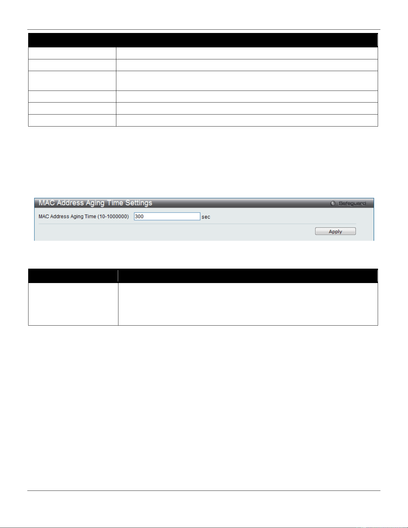
xStack® DGS-3420 Series Layer 2 Managed Stackable Gigabit Switch Web UI Reference Guide
122
Parameter Description
State
Enable or disable MAC notification globally on the Switch
Interval (1-2147483647)
The time in seconds between notifications. Value range to use is 1 to 2147483647.
History Size (1-500)
The maximum number of entries listed in the history log used for notification. Up to
500 entries can be specified.
Unit
Select the unit you wish to configure.
From Port / To Port
Select the starting and ending ports for MAC notification.
State
Enable MAC Notification for the ports selected using the drop-down menu.
Click the Apply button to accept the changes made for each individual section.
MAC Address Aging Time Settings
Users can configure the MAC Address aging time on the Switch.
To view the following window, click L2 Features > FDB > MAC Address Aging Time Settings, as show below:
Figure 4-47 MAC Address Aging Time Settings window
The fields that can be configured are described below:
Parameter Description
MAC Address Aging Time
(10-1000000)
This field specify the length of time a learned MAC Address will remain in the
forwarding table without being accessed (that is, how long a learned MAC Address is
allowed to remain idle). To change this option, type in a different value representing
the MAC address’ age-out time in seconds. The MAC Address Aging Time can be set
to any value between 10 and 1000000 seconds. The default setting is 300 seconds.
Click the Apply button to accept the changes made.
MAC Address Table
This allows the Switch's MAC address forwarding table to be viewed. When the Switch learns an association between
a MAC address, VLAN and a port number, it makes an entry into its forwarding table. These entries are then used to
forward packets through the Switch.
To view the following window, click L2 Features > FDB > MAC Address Table, as show below:
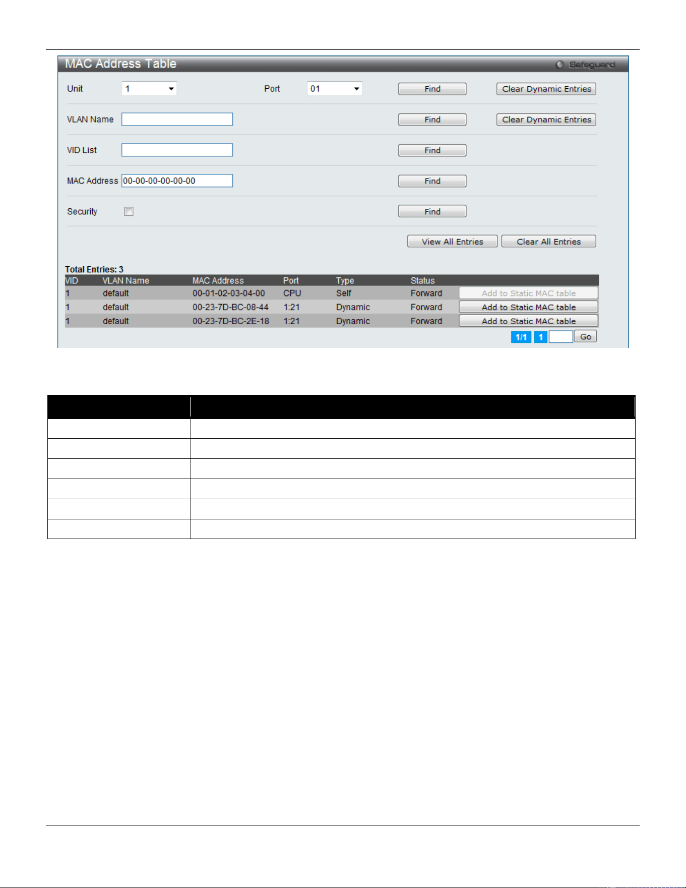
xStack® DGS-3420 Series Layer 2 Managed Stackable Gigabit Switch Web UI Reference Guide
123
Figure 4-48 MAC Address Table window
The fields that can be configured are described below:
Parameter Description
Unit
Select the unit you wish to configure.
Port
The port to which the MAC address below corresponds.
VLAN Name
Enter a VLAN Name for the forwarding table to be browsed by.
VID List
Enter a VID list of VLAN for the forwarding table to be browsed by.
MAC Address
Enter a MAC address for the forwarding table to be browsed by.
Security
Tick the check box to diaplsy the FDB entries that are created by the security module.
Click the Find button to locate a specific entry based on the information entered.
Click the Clear Dynamic Entries button to delete all dynamic entries of the address table.
Click the View All Entries button to display all the existing entries.
Click the Clear All Entries button to remove all the entries listed in the table.
Click the Add to Static MAC table button to add the specific entry to the Static MAC table.
Enter a page number and click the Go button to navigate to a specific page when multiple pages exist.
ARP & FDB Table
On this page the user can find the ARP and FDB table parameters.
To view the following window, click L2 Features > FDB > ARP & FDB Table, as show below:
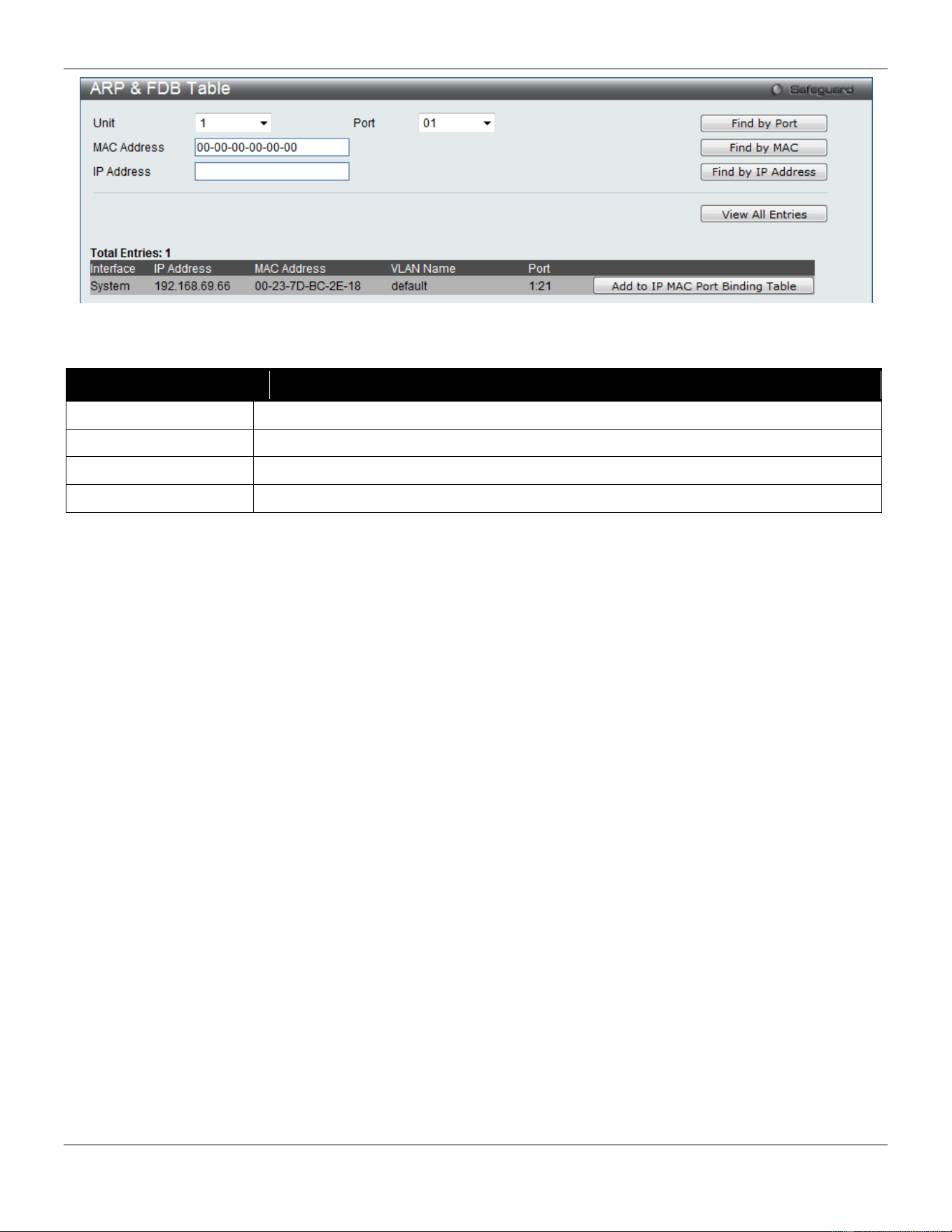
xStack® DGS-3420 Series Layer 2 Managed Stackable Gigabit Switch Web UI Reference Guide
124
Figure 4-49 ARP & FDB Table window
The fields that can be configured are described below:
Parameter Description
Unit
Select the unit you wish to configure.
Port
Select the port number to use for this configuration.
MAC Address
Enter the MAC address to use for this configuration.
IP Address
Enter the IP address the use for this configuration.
Click the Find by Port button to locate a specific entry based on the port number selected.
Click the Find by MAC button to locate a specific entry based on the MAC address entered.
Click the Find by IP Address button to locate a specific entry based on the IP address entered.
Click the View All Entries button to display all the existing entries.
Click the Add to IP MAC Port Binding Table to add the specific entry to the IMPB Entry Settings window.
L2 Multicast Control
IGMP Proxy
Based on IGMP forwarding, the IGMP proxy runs the host part of IGMP on the upstream and router part of IGMP on
the downstream, and replicates multicast traffic across VLANs on devices such as the edge boxes. It reduces the
number of the IGMP control packets transmitted to the core network.
IGMP Proxy Settings
This window is used to configure the IGMP proxy state and IGMP proxy upstream interface in this page.
To view the following window, click L2 Features > L2 Multicast Control > IGMP Proxy > IGMP Proxy Settings, as
show below:
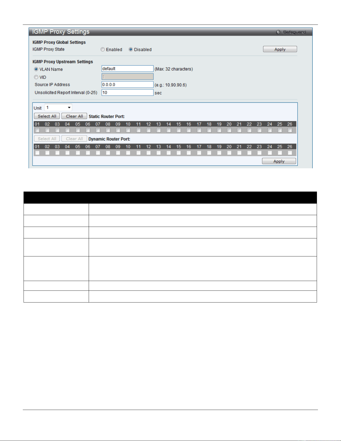
xStack® DGS-3420 Series Layer 2 Managed Stackable Gigabit Switch Web UI Reference Guide
125
Figure 4-50 IGMP Proxy Settings window
The fields that can be configured are described below:
Parameter Description
IGMP Proxy State
Use the radio buttons to enable or disable the IGMP Proxy Global State.
VLAN Name
Click the radio button and enter the VLAN name for the interface.
VID
Click the radio button and enter the VLAN ID for the interface.
Source IP Address
Enter the source IP address of the upstream protocol packet. If it is not specified, zero IP
address will be used as the protocol source IP address.
Unsolicited Report
Interval (0-25)
The Unsolicited report interval. It is the time between repetitions of the host's initial report
of membership in a group. Default is 10 seconds. If set to 0, it means to send only one
report packet.
Unit
Select the unit you wish to configure.
Static Router Port
Select the port that will be included in this configuration.
Click the Apply button to accept the changes made for each individual section.
Click the Select All button to select all the ports for configuration.
Click the Clear All button to unselect all the ports for configuration.
IGMP Proxy Downstream Settings
This window is used to configure the IGMP proxy downstream interface in this page. The IGMP proxy downstream
interface must be an IGMP snooping enabled VLAN.
To view the following window, click L2 Features > L2 Multicast Control > IGMP Proxy > IGMP Proxy Downstream
Settings, as show below:
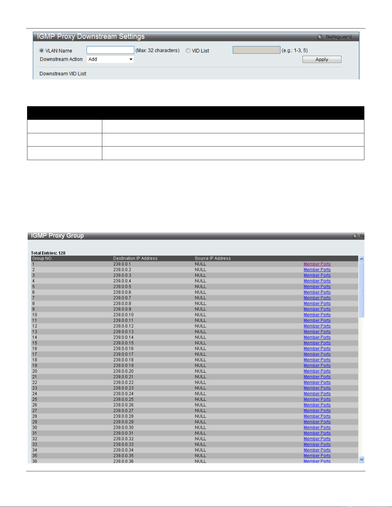
xStack® DGS-3420 Series Layer 2 Managed Stackable Gigabit Switch Web UI Reference Guide
126
Figure 4-51 IGMP Proxy Downstream Settings window
The fields that can be configured are described below:
Parameter Description
VLAN Name
Enter the VLAN Name which belongs to the IGMP proxy downstream interface.
VID List
Enter a list of VLANs which belong to the IGMP proxy downstream interface.
Downstream Action
Use the drop-down menu to add or delete a downstream interface.
Click the Apply button to accept the changes made.
IGMP Proxy Group
This window displays the IGMP Proxy Group settings.
To view the following window, click L2 Features > L2 Multicast Control > IGMP Proxy > IGMP Proxy Group, as
show below:
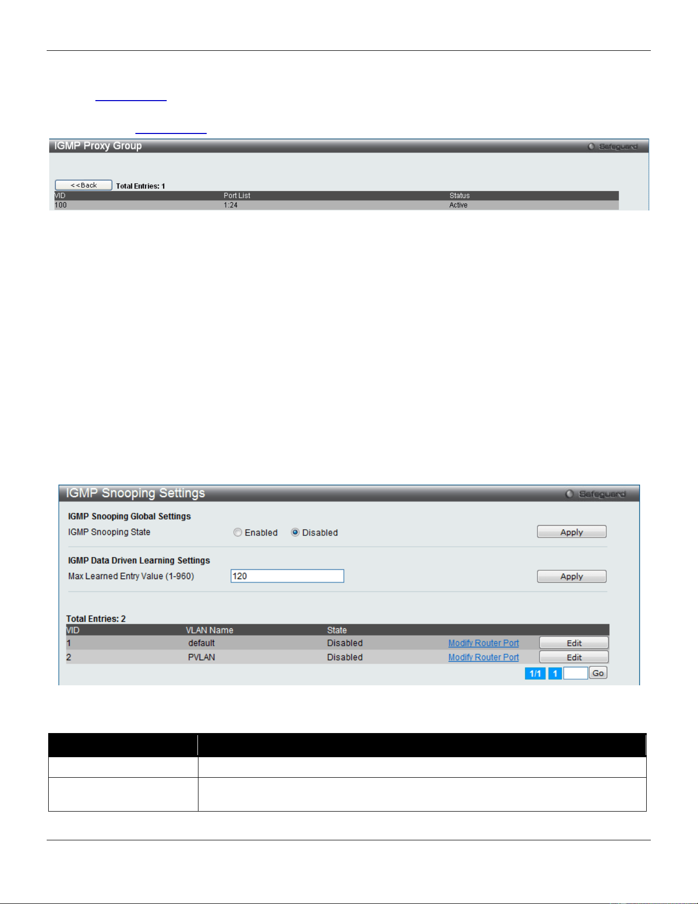
xStack® DGS-3420 Series Layer 2 Managed Stackable Gigabit Switch Web UI Reference Guide
127
Figure 4-52 IGMP Proxy Group window
Click the Member Ports link to view the IGMP proxy member port information.
After clicking the Member Ports option, the following window will appear.
Figure 4-53 IGMP Proxy Group – Member Ports window
IGMP Snooping
Internet Group Management Protocol (IGMP) snooping allows the Switch to recognize IGMP queries and reports sent
between network stations or devices and an IGMP host. When enabled for IGMP snooping, the Switch can open or
close a port to a specific device based on IGMP messages passing through the Switch.
IGMP Snooping Settings
In order to use IGMP Snooping it must first be enabled for the entire Switch under IGMP Global Settings at the top of
the window. You may then fine-tune the settings for each VLAN by clicking the corresponding Edit button. When
enabled for IGMP snooping, the Switch can open or close a port to a specific multicast group member based on IGMP
messages sent from the device to the IGMP host or vice versa. The Switch monitors IGMP messages and discontinues
forwarding multicast packets when there are no longer hosts requesting that they continue.
To view the following window, click L2 Features > L2 Multicast Control > IGMP Snooping > IGMP Snooping
Settings, as show below:
Figure 4-54 IGMP Snooping Settings window
The fields that can be configured are described below:
Parameter Description
IGMP Snooping State
Use the radio buttons to enable or disable the IGMP Snooping state.
Max Learned Entry Value
Enter the maximum number of groups that can be learned by data driven feature here.
This value must be between 1 and 960.
Click the Apply button to accept the changes made for each individual section.
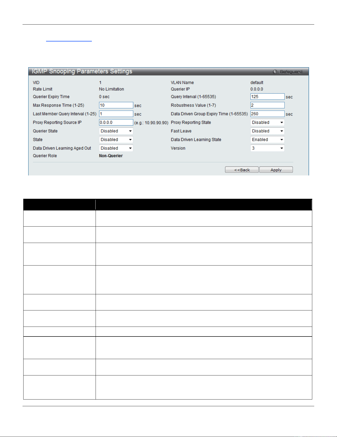
xStack® DGS-3420 Series Layer 2 Managed Stackable Gigabit Switch Web UI Reference Guide
128
Click the Edit button to configure the IGMP Snooping Parameters Settings.
Click the Modify Router Port link to configure the IGMP Snooping Router Port Settings.
Enter a page number and click the Go button to navigate to a specific page when multiple pages exist.
After clicking the Edit button, the following page will appear:
Figure 4-55 IGMP Snooping Parameters Settings window
The fields that can be configured are described below:
Parameter Description
Query Interval (1-65535)
Specify the amount of time in seconds between general query transmissions. The
default setting is 125 seconds..
Max Response Time (1-
25)
Specify the maximum time in seconds to wait for reports from members. The default
setting is 10 seconds.
Robustness Value (1-7)
Provides fine-tuning to allow for expected packet loss on a subnet. The value of the
robustness value is used in calculating the following IGMP message intervals: By
default, the robustness variable is set to 2.
Last Member Query
Interval (1-25)
Specify the maximum amount of time between group-specific query messages,
including those sent in response to leave-group messages. You might lower this
interval to reduce the amount of time it takes a router to detect the loss of the last
member of a group.
Data Driven Group
Expiry Time
Specifies the data driven group lifetime value used. This value is only applicable if the
aged out option is enabled.
Proxy Reporting Source
IP
Enter the proxy reporting source IP address.
Proxy Reporting State
Use the drop-down menu to enable and disable the proxy report state.
Querier State
If this state is enable, it allows the Switch to be selected as an IGMP Querier that
sends IGMP query packets. If this state is disabled, then the Switch will not play the
role as a Querier.
Fast Leave
Enable or disable the IGMP snooping fast leave function. If enabled, the membership
is immediately removed when the system receive the IGMP leave message.
State
Used to enable or disable IGMP snooping for the specified VLAN. This option is
disabled by default.
Note: If the Layer 3 router connected to the switch provides only the IGMP proxy
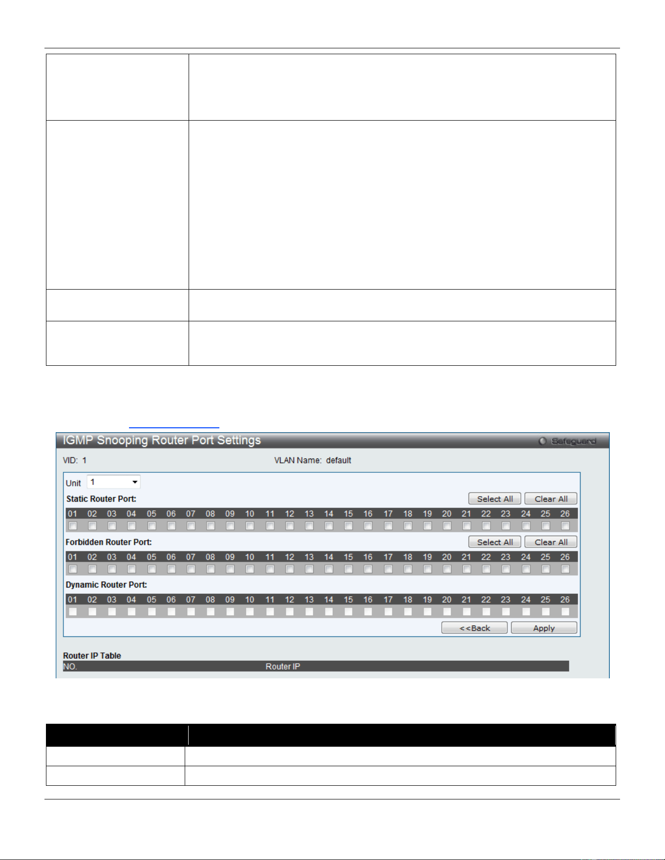
xStack® DGS-3420 Series Layer 2 Managed Stackable Gigabit Switch Web UI Reference Guide
129
function but does not provide the multicast routing function, then this state
must be configured as disabled. Otherwise, if the Layer 3 router is not selected
as the querier, it will not send the IGMP query packet. Since it will not also
send the multicast-routing protocol packet, the port will be timed out as a router
port.
Data Driven Learning
State
Specifies to enable or disable the data driven learning of an IGMP snooping group.
When data-driven learning is enabled for a VLAN, when the switch receives IP
multicast traffic on this VLAN, an IGMP snooping group will be created. The learning
of an entry is not activated by an IGMP membership registration, but activated by
traffic. For an ordinary IGMP snooping entry, the IGMP protocol will take care of the
aging out of the entry. For a data-driven entry, the entry can be specified not to aged
out by the aged timer. When data driven learning is enabled and the data driven table
is not full, the multicast filtering mode for all ports will be ignored. The multicast
packets will be forwarded to router ports. If the data driven learning table is full,
multicast packets will be forwarded according to the multicast filtering mode. Note that
if a data-driven group is created and IGMP member ports are learned later on, the
entry will become an ordinary IGMP snooping entry. The aging out mechanism will
follow the ordinary IGMP snooping entry.
Data Driven Learning
Aged Out
Specifies that the aging out of the entry will be enabled or disabled.
Version
Specify the version of IGMP packet that will be sent by this port. If an IGMP packet
received by the interface has a version higher than the specified version, this packet
will be forwarded from the router ports or VLAN flooding.
Click the Apply button to accept the changes made.
Click the <<Back button to discard the changes made and return to the previous page.
After clicking the Modify Router Port link, the following page will appear:
Figure 4-56 IGMP Snooping Router Port Settings window
The fields that can be configured are described below:
Parameter Description
Unit
Select the unit you wish to configure.
Static Router Port
This section is used to designate a range of ports as being connected to multicast-
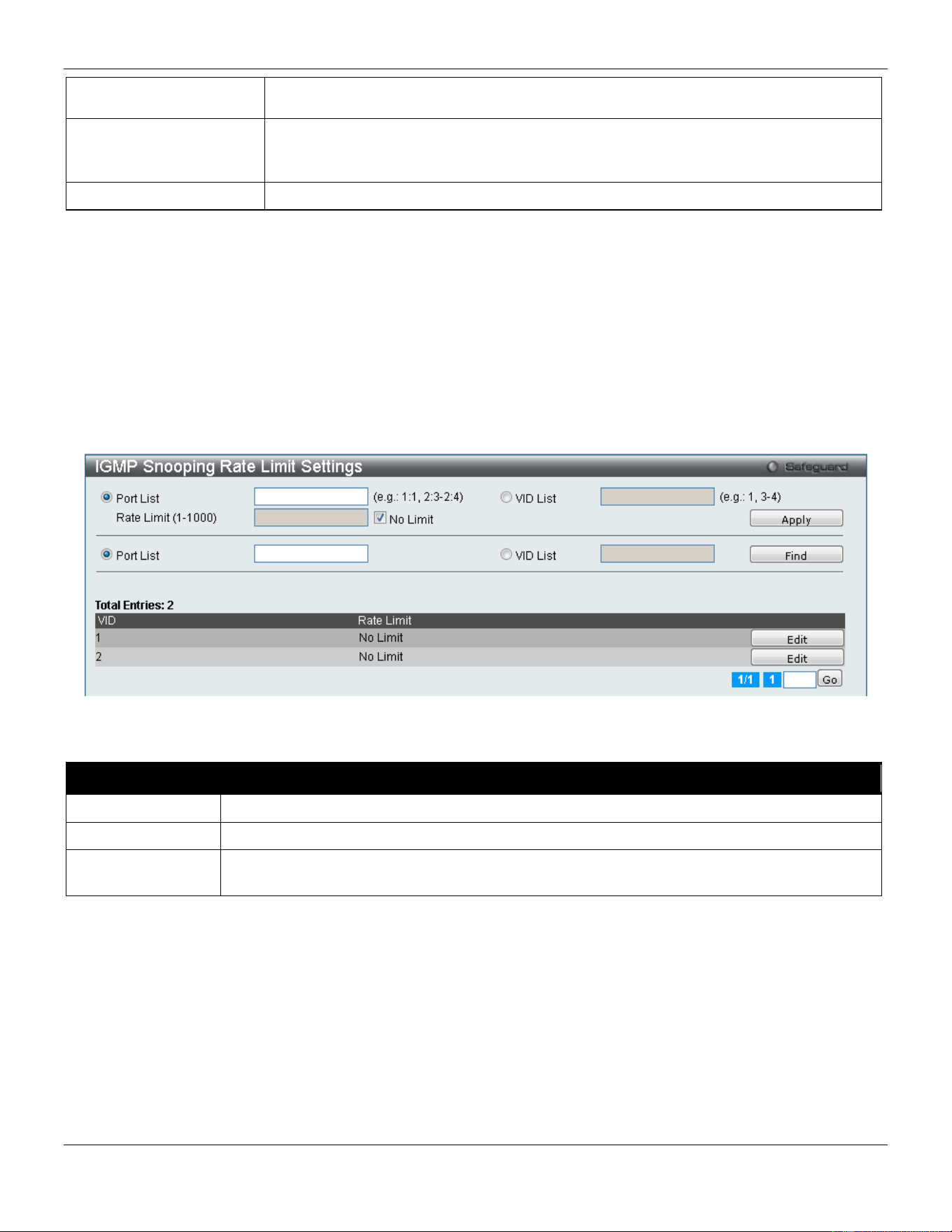
xStack® DGS-3420 Series Layer 2 Managed Stackable Gigabit Switch Web UI Reference Guide
130
enabled routers. This will ensure that all packets with such a router as its destination
will reach the multicast-enabled router regardless of the protocol.
Forbidden Router Port
This section is used to designate a range of ports as being not connected to multicast-
enabled routers. This ensures that the forbidden router port will not propagate routing
packets out.
Dynamic Router Port
Displays router ports that have been dynamically configured.
Click the Select All button to select all the ports for configuration.
Click the Clear All button to unselect all the ports for configuration.
Click the Apply button to accept the changes made.
Click the <<Back button to discard the changes made and return to the previous page.
IGMP Snooping Rate Limit Settings
On this page the user can configure the IGMP snooping rate limit parameters.
To view the following window, click L2 Features > L2 Multicast Control > IGMP Snooping > IGMP Snooping Rate
Limit Settings, as show below:
Figure 4-57 IGMP Snooping Rate Limit Settings window
The fields that can be configured are described below:
Parameter Description
Port List
Enter the port list used for this configuration.
VID List
Enter the VID list used for this configuration.
Rate Limit (1-
1000)
Enter the IGMP snooping rate limit used. By selecting the No Limit check box, the rate limit
for the entered port(s) will be ignored.
Click the Apply button to accept the changes made.
Click the Find button to locate a specific entry based on the information entered.
Click the Edit button to re-configure the specific entry.
Enter a page number and click the Go button to navigate to a specific page when multiple pages exist.
IGMP Snooping Static Group Settings
Users can view the Switch’s IGMP Snooping Group Table. IGMP Snooping allows the Switch to read the Multicast
Group IP address and the corresponding MAC address from IGMP packets that pass through the Switch.
To view the following window, click L2 Features > L2 Multicast Control > IGMP Snooping > IGMP Snooping Static
Group Settings, as show below:
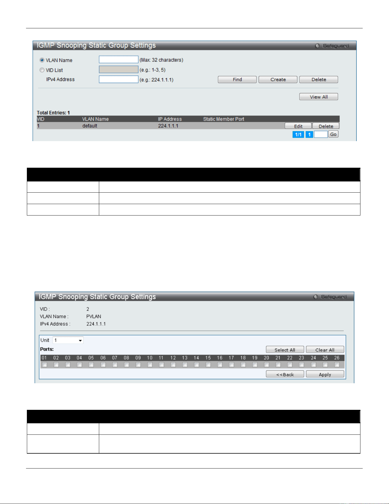
xStack® DGS-3420 Series Layer 2 Managed Stackable Gigabit Switch Web UI Reference Guide
131
Figure 4-58 IGMP Snooping Static Group Settings window
The fields that can be configured are described below:
Parameter Description
VLAN Name
The VLAN Name of the multicast group.
VID List
The VID List of the multicast group.
IPv4 Address
Enter the IPv4 address.
Click the Find button to locate a specific entry based on the information entered.
Click the Create button to add a new entry based on the information entered.
Click the Delete button to remove the specific entry based on the information entered.
Click the View All button to display all the existing entries.
Click the Edit button to re-configure the specific entry.
Enter a page number and click the Go button to navigate to a specific page when multiple pages exist.
After clicking the Edit button, the following page will appear:
Figure 4-59 IGMP Snooping Static Group Settings – Edit window
The fields that can be configured are described below:
Parameter Description
Unit
Select the unit you wish to configure.
Ports
Select the appropriate ports individually to include them in the IGMP snooping static group
settings.
Click the Select All button to select all the ports for configuration.
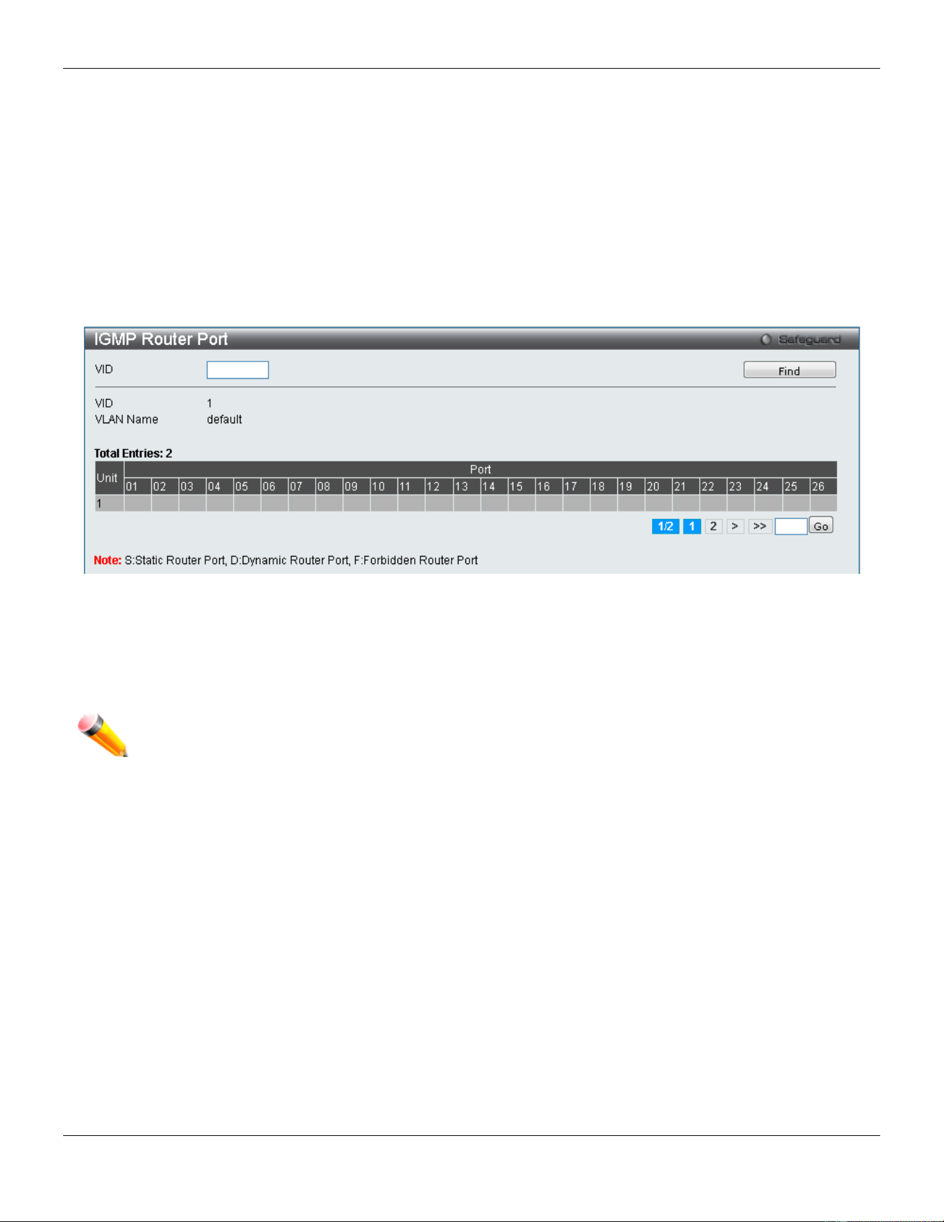
xStack® DGS-3420 Series Layer 2 Managed Stackable Gigabit Switch Web UI Reference Guide
132
Click the Clear All button to unselect all the ports for configuration.
Click the Apply button to accept the changes made.
Click the <<Back button to discard the changes made and return to the previous page.
IGMP Router Port
Users can display which of the Switch’s ports are currently configured as router ports. A router port configured by a
user (using the console or Web-based management interfaces) is displayed as a static router port, designated by S. A
router port that is dynamically configured by the Switch is designated by D, while a Forbidden port is designated by F.
To view the following window, click L2 Features > L2 Multicast Control > IGMP Snooping > IGMP Router Port, as
show below:
Figure 4-60 IGMP Router Port window
Enter a VID (VLAN ID) in the field at the top of the window.
Click the Find button to locate a specific entry based on the information entered.
Enter a page number and click the Go button to navigate to a specific page when multiple pages exist.
NOTE: The abbreviations used on this page are Static Router Port (S), Dynamic Router Port (D) and
Forbidden Router Port (F).
IGMP Snooping Group
Users can view the Switch’s IGMP Snooping Group Table. IGMP Snooping allows the Switch to read the Multicast
Group IP address and the corresponding MAC address from IGMP packets that pass through the Switch.
To view the following window, click L2 Features > L2 Multicast Control > IGMP Snooping > IGMP Snooping Group,
as show below:
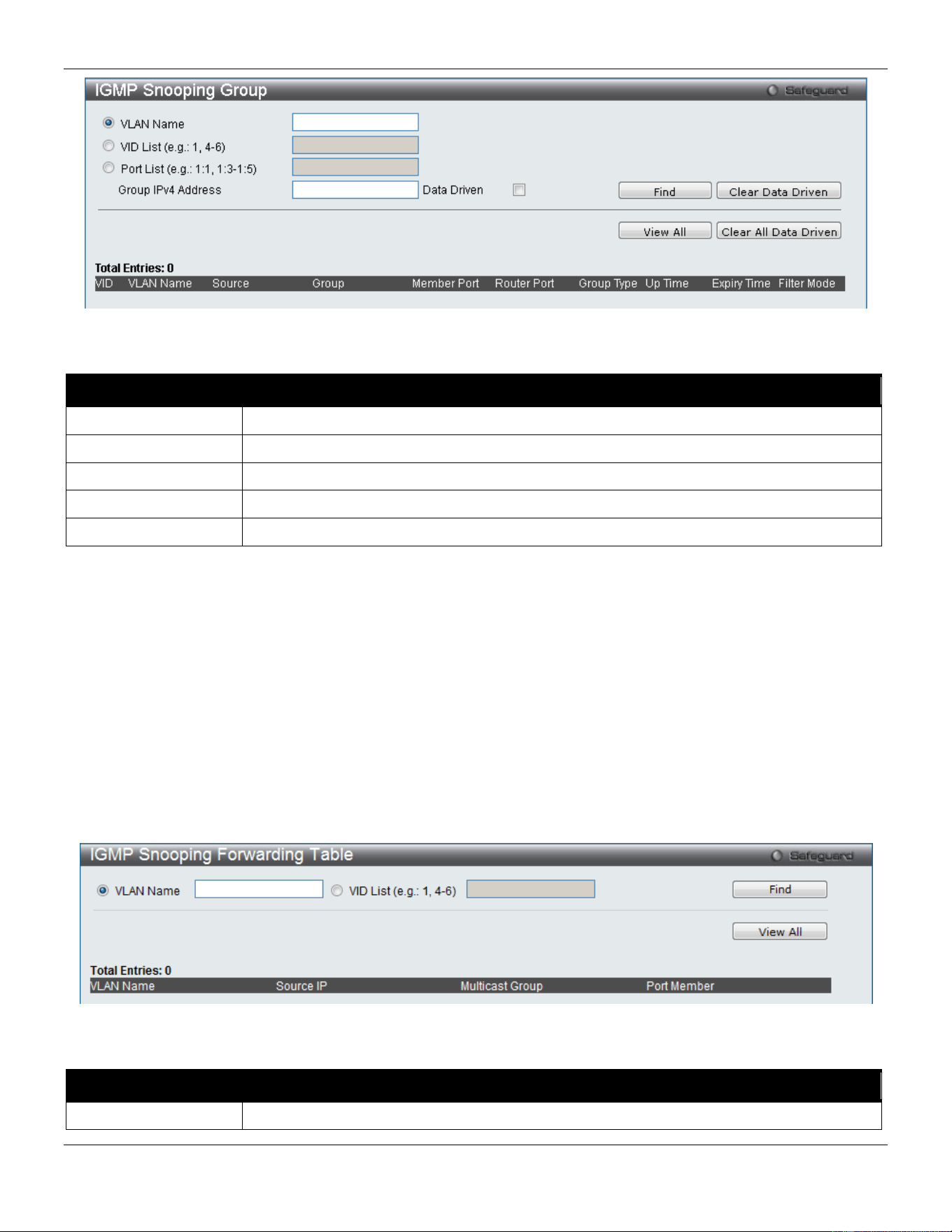
xStack® DGS-3420 Series Layer 2 Managed Stackable Gigabit Switch Web UI Reference Guide
133
Figure 4-61 IGMP Snooping Group window
The fields that can be configured are described below:
Parameter Description
VLAN Name
The VLAN Name of the multicast group.
VID List
The VLAN ID list of the multicast group.
Port List
Specify the port number(s) used to find a multicast group.
Group IPv4 Address
Enter the IPv4 address.
Data Driven
Tick this option to enable or disable the data driven learning of an IGMP snooping group.
Click the Find button to locate a specific entry based on the information entered.
Click the View All button to display all the existing entries.
Click the Clear Data Driven button to clear data driven information for the specified entry.
Click the Clear All Data Driven button to clear data driven information for all entries.
IGMP Snooping Forwarding Table
This page displays the switch’s current IGMP snooping forwarding table. It provides an easy way for user to check the
list of ports that the multicast group comes from and specific sources that it will be forwarded to. The packet comes
from the source VLAN. They will be forwarded to the forwarding VLAN. The IGMP snooping further restricts the
forwarding ports.
To view the following window, click L2 Features > L2 Multicast Control > IGMP Snooping > IGMP Snooping
Forwarding Table, as show below:
Figure 4-62 IGMP Snooping Forwarding Table window
The fields that can be configured are described below:
Parameter Description
VLAN Name
The VLAN Name of the multicast group.
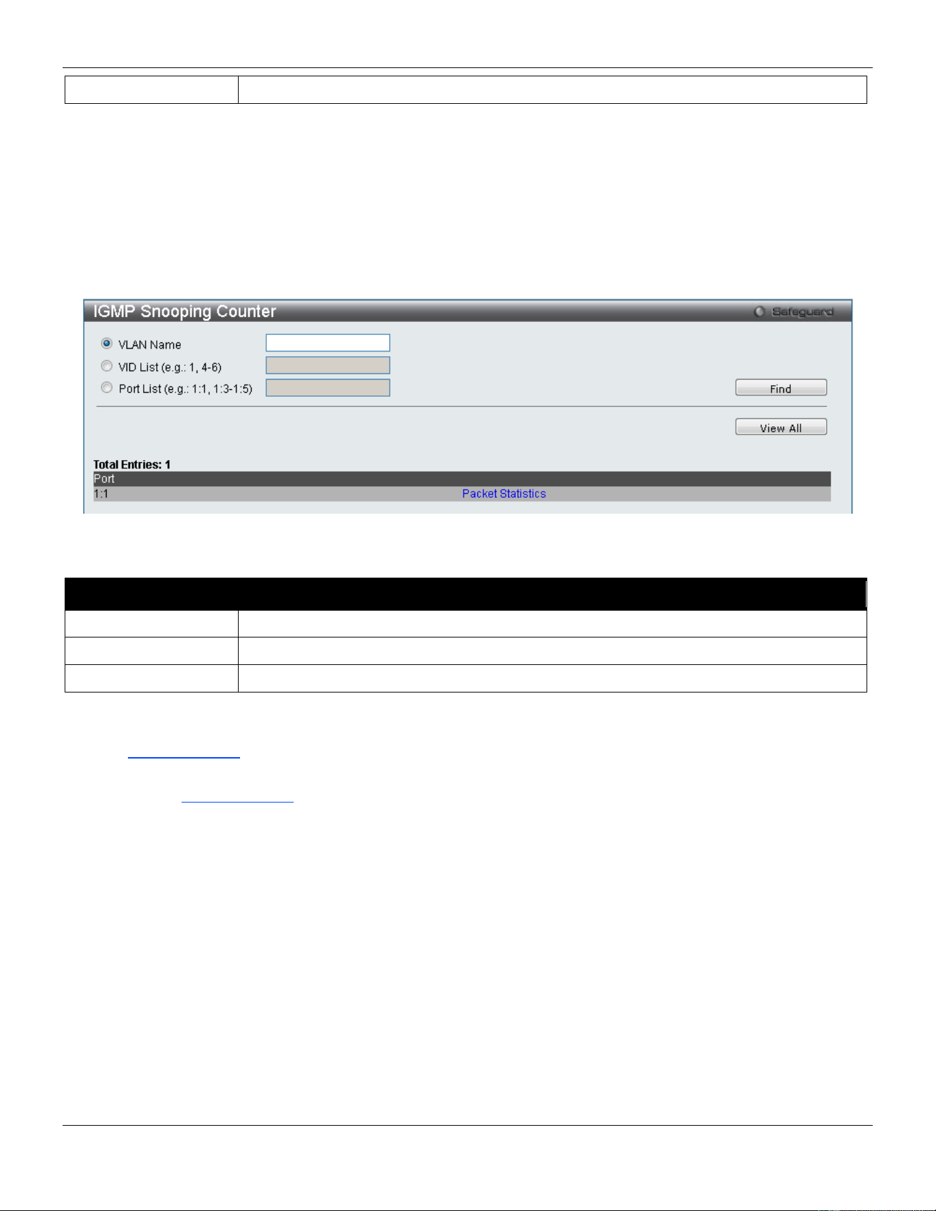
xStack® DGS-3420 Series Layer 2 Managed Stackable Gigabit Switch Web UI Reference Guide
134
VID List
The VLAN ID list of the multicast group.
Click the Find button to locate a specific entry based on the information entered.
Click the View All button to display all the existing entries.
IGMP Snooping Counter
Users can view the switch’s IGMP Snooping counter table.
To view the following window, click L2 Features > L2 Multicast Control > IGMP Snooping > IGMP Snooping
Counter, as show below:
Figure 4-63 IGMP Snooping Counter window
The fields that can be configured are described below:
Parameter Description
VLAN Name
The VLAN Name of the multicast group.
VID List
The VLAN ID list of the multicast group.
Port List
The Port List of the multicast group.
Click the Find button to locate a specific entry based on the information entered.
Click the View All button to display all the existing entries.
Click the Packet Statistics link to view the IGMP Snooping Counter Table.
After clicking the Packet Statistics link, the following page will appear:
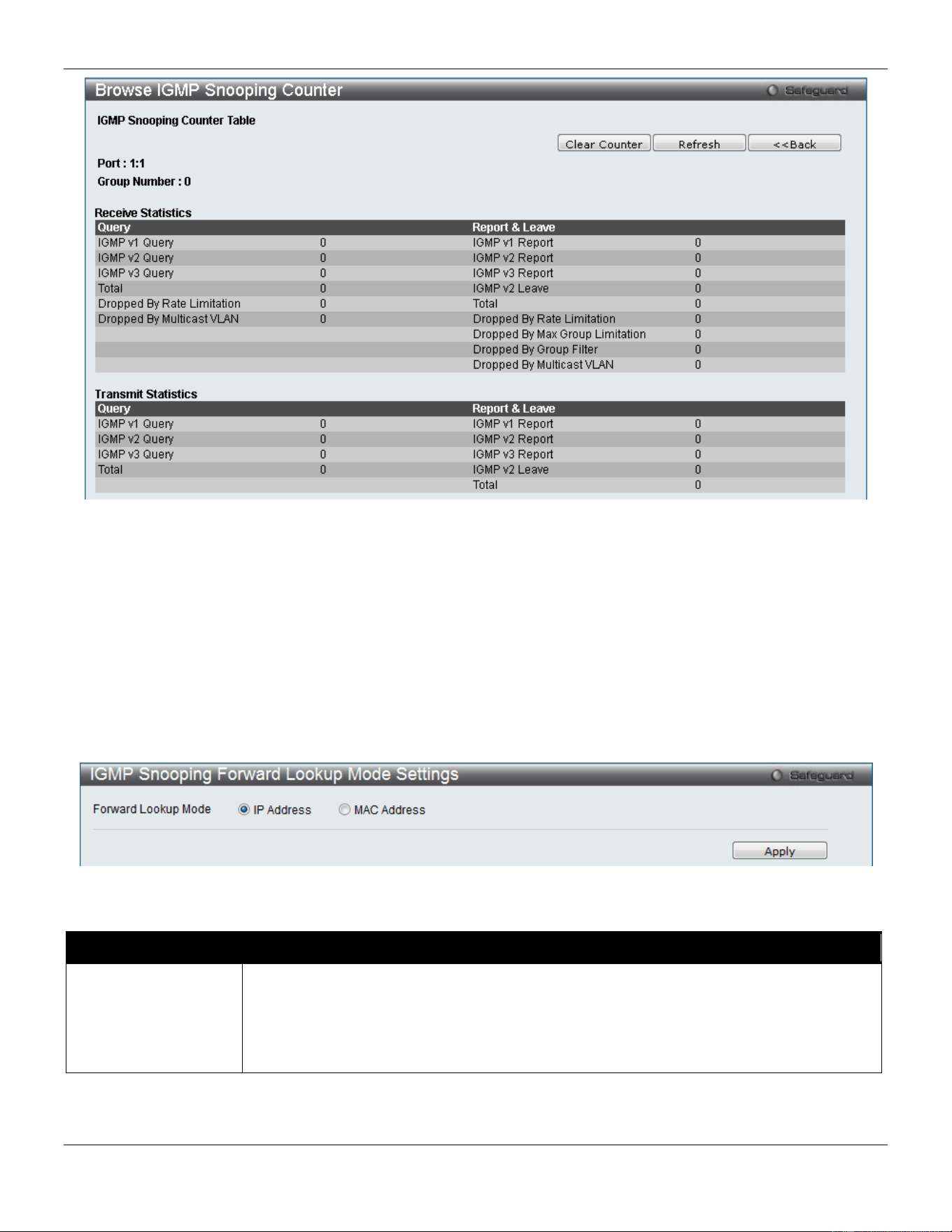
xStack® DGS-3420 Series Layer 2 Managed Stackable Gigabit Switch Web UI Reference Guide
135
Figure 4-64 Browse IGMP Snooping Counter window
Click the Clear Counter button to clear all the information displayed in the fields.
Click the Refresh button to refresh the display table so that new information will appear.
Click the <<Back button to return to the previous page.
IGMP Snooping Forward Lookup Mode Settings
This window is used to configure the IGMP Snooping forwarding mode settings.
To view the following window, click L2 Features > L2 Multicast Control > IGMP Snooping > IGMP Snooping
Forward Lookup Mode Settings, as show below:
Figure 4-65 IGMP Snooping Forward Lookup Mode Settings window
The fields that can be configured are described below:
Parameter Description
Forward Lookup
Mode
Select the appropriate IGMP Snooping forwarding lookup mode here.
IP Address - Specifies that the multicast forwarding lookup will be based on the IP
address.
MAC Address - Specifies that the multicast forwarding lookup will be based on the MAC
address
Click the Apply button to accept the changes made.
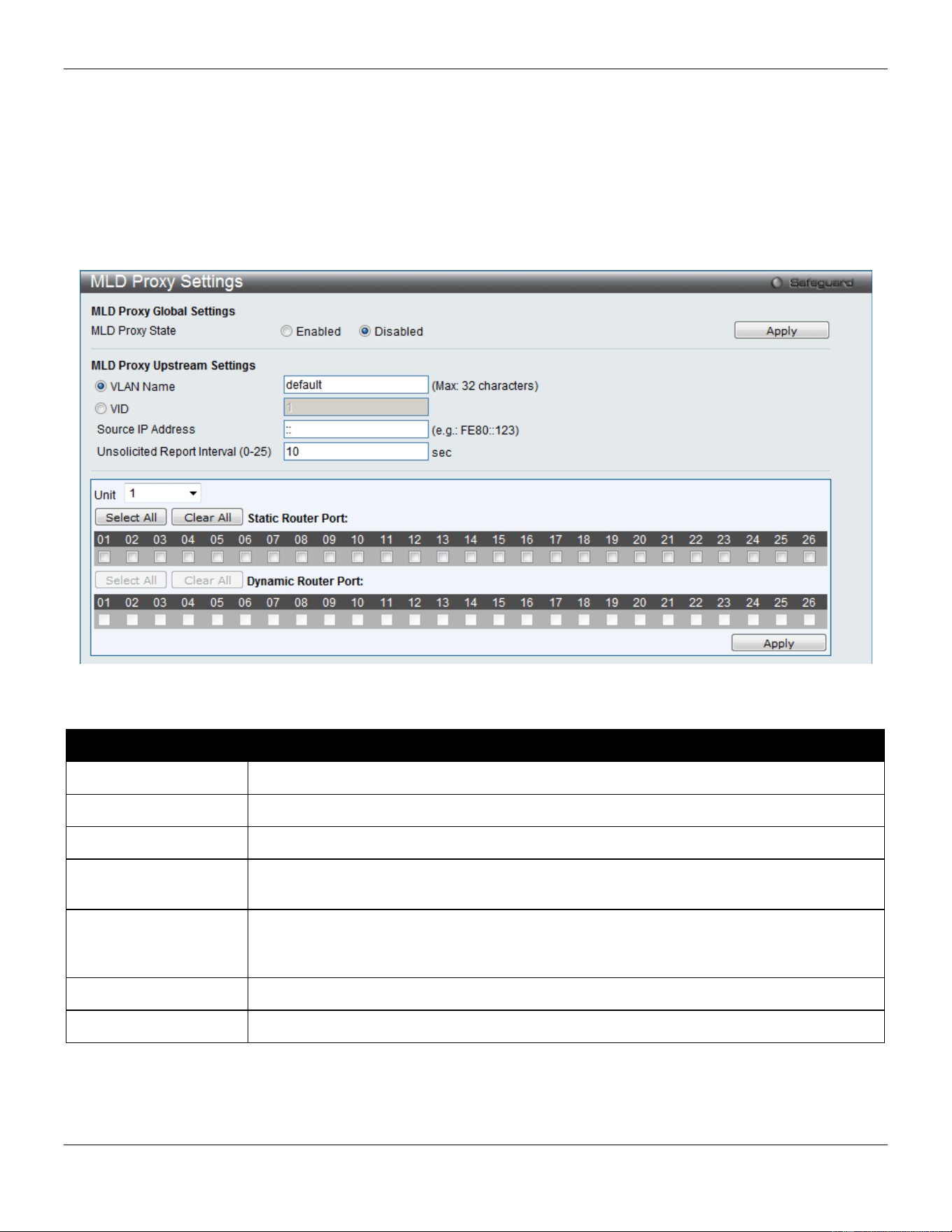
xStack® DGS-3420 Series Layer 2 Managed Stackable Gigabit Switch Web UI Reference Guide
136
MLD Proxy
MLD Proxy Settings
This window is used to configure the MLD proxy state and MLD proxy upstream interface.
To view the following window, click L2 Features > L2 Multicast Control > MLD Proxy > MLD Proxy Settings, as
show below:
Figure 4-66 MLD Proxy Settings window
The fields that can be configured are described below:
Parameter Description
MLD Proxy State
Use the radio buttons to enable or disable the MLD Proxy Global State.
VLAN Name
Click the radio button and enter the VLAN name for the interface.
VID
Click the radio button and enter the VLAN ID for the interface.
Source IP Address
Enter the source IPv6 address of the upstream protocol packet. If it is not specified, zero
IP address will be used as the protocol source IP address.
Unsolicited Report
Interval (0-25)
The Unsolicited report interval. It is the time between repetitions of the host's initial report
of membership in a group. Default is 10 seconds. If set to 0, it means to send only one
report packet.
Unit
Select the unit you wish to configure.
Static Router Port
Select the port that will be included in this configuration.
Click the Apply button to accept the changes made for each individual section.
Click the Select All button to select all the ports for configuration.
Click the Clear All button to unselect all the ports for configuration.
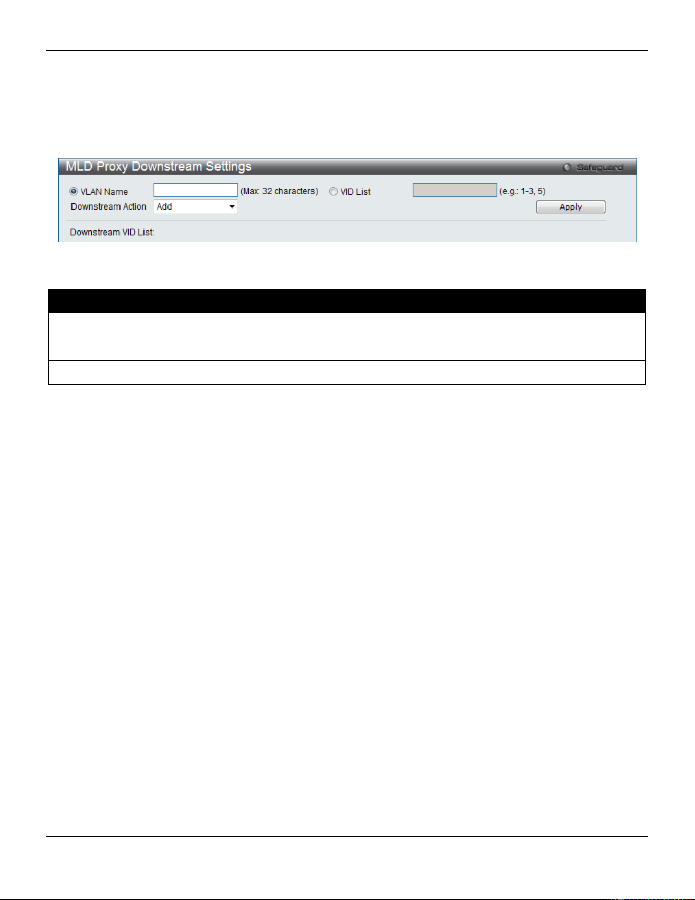
xStack® DGS-3420 Series Layer 2 Managed Stackable Gigabit Switch Web UI Reference Guide
137
MLD Proxy Downstream Settings
This window is used to configure the MLD proxy downstream interface in this page. The MLD proxy downstream
interface must be an MLD snooping enabled VLAN.
To view the following window, click L2 Features > L2 Multicast Control > MLD Proxy > MLD Proxy Downstream
Settings, as show below:
Figure 4-67 MLD Proxy Downstream Settings window
The fields that can be configured are described below:
Parameter Description
VLAN Name
Enter the VLAN Name which belongs to the MLD proxy downstream interface.
VID List
Enter a list of VLANs which belong to the MLD proxy downstream interface.
Downstream Action
Use the drop-down menu to add or delete a downstream interface.
Click the Apply button to accept the changes made.
MLD Proxy Group
This window displays the MLD Proxy Group settings.
To view the following window, click L2 Features > L2 Multicast Control > MLD Proxy > MLD Proxy Group, as show
below:
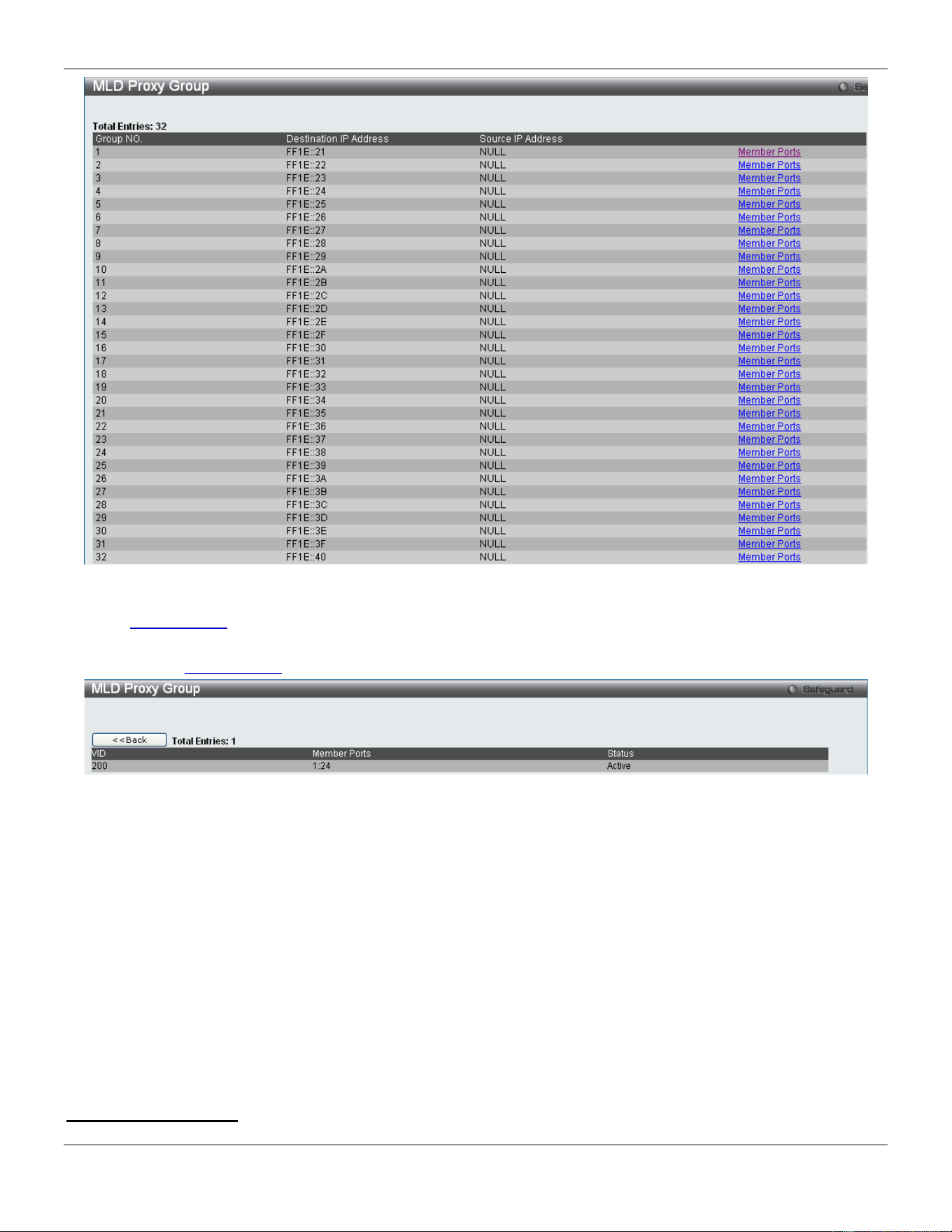
xStack® DGS-3420 Series Layer 2 Managed Stackable Gigabit Switch Web UI Reference Guide
138
Figure 4-68 MLD Proxy Group window
Click the Member Ports link to view the MLD proxy member port information.
After clicking the Member Ports option, the following window will appear.
Figure 4-69 MLD Proxy Group – Member Ports window
MLD Snooping
Multicast Listener Discovery (MLD) Snooping is an IPv6 function used similarly to IGMP snooping in IPv4. It is used to
discover ports on a VLAN that are requesting multicast data. Instead of flooding all ports on a selected VLAN with
multicast traffic, MLD snooping will only forward multicast data to ports that wish to receive this data through the use of
queries and reports produced by the requesting ports and the source of the multicast traffic.
MLD snooping is accomplished through the examination of the layer 3 part of an MLD control packet transferred
between end nodes and a MLD router. When the Switch discovers that this route is requesting multicast traffic, it adds
the port directly attached to it into the correct IPv6 multicast table, and begins the process of forwarding multicast traffic
to that port. This entry in the multicast routing table records the port, the VLAN ID, and the associated multicast IPv6
multicast group address, and then considers this port to be an active listening port. The active listening ports are the
only ones to receive multicast group data.
MLD Control Messages
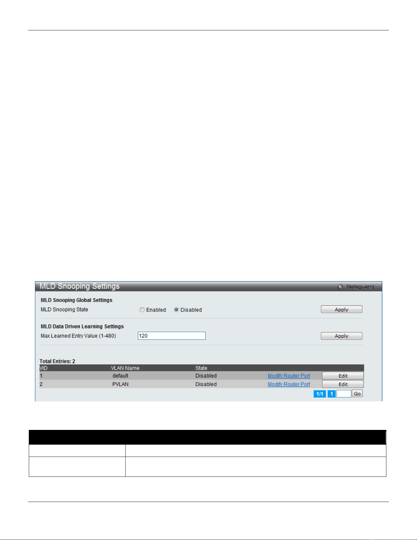
xStack® DGS-3420 Series Layer 2 Managed Stackable Gigabit Switch Web UI Reference Guide
139
Three types of messages are transferred between devices using MLD snooping. These three messages are all defined
by four ICMPv6 packet headers, labeled 130, 131, 132, and 143.
1. Multicast Listener Query – Similar to the IGMPv2 Host Membership Query for IPv4, and labeled as 130 in the
ICMPv6 packet header, this message is sent by the router to ask if any link is requesting multicast data. There
are two types of MLD query messages emitted by the router. The General Query is used to advertise all
multicast addresses that are ready to send multicast data to all listening ports, and the Multicast Specific query,
which advertises a specific multicast address that is also ready. These two types of messages are
distinguished by a multicast destination address located in the IPv6 header and a multicast address in the
Multicast Listener Query Message.
2. Multicast Listener Report, Version 1 – Comparable to the Host Membership Report in IGMPv2, and labeled
as 131 in the ICMPv6 packet header, this message is sent by the listening port to the Switch stating that it is
interested in receiving multicast data from a multicast address in response to the Multicast Listener Query
message.
3. Multicast Listener Done – Akin to the Leave Group Message in IGMPv2, and labeled as 132 in the ICMPv6
packet header, this message is sent by the multicast listening port stating that it is no longer interested in
receiving multicast data from a specific multicast group address, therefore stating that it is “done” with the
multicast data from this address. Once this message is received by the Switch, it will no longer forward
multicast traffic from a specific multicast group address to this listening port.
4. Multicast Listener Report, Version 2 - Comparable to the Host Membership Report in IGMPv3, and labeled
as 143 in the ICMPv6 packet header, this message is sent by the listening port to the Switch stating that it is
interested in receiving multicast data from a multicast address in response to the Multicast Listener Query
message.
MLD Snooping Settings
Users can configure the settings for MLD snooping.
To view the following window, click L2 Features > L2 Multicast Control > MLD Snooping > MLD Snooping Settings,
as show below:
Figure 4-70 MLD Snooping Settings window
The fields that can be configured are described below:
Parameter Description
MLD Snooping State
Click the radio buttons to enable or disable the MLD snooping state.
Max Learned Entry Value
Enter the maximum number of groups that can be learned by data driven feature
here. This value must be between 1 and 480.
Click the Apply button to accept the changes made for each individual section.
Click the Edit button to configure the MLD Snooping Parameters Settings for a specific entry.
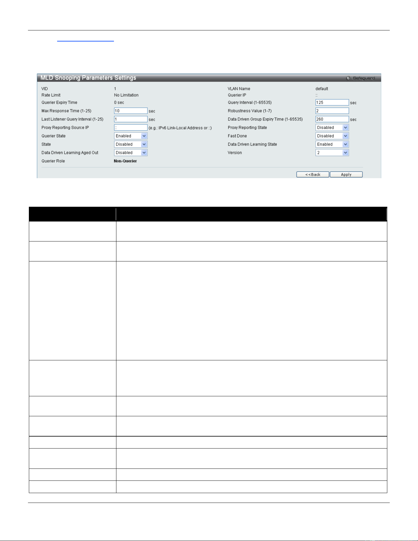
xStack® DGS-3420 Series Layer 2 Managed Stackable Gigabit Switch Web UI Reference Guide
140
Click the Modify Router Port link to configure the MLD Snooping Router Port Settings for a specific entry.
Enter a page number and click the Go button to navigate to a specific page when multiple pages exist.
After clicking the Edit button, the following page will appear:
Figure 4-71 MLD Snooping Parameters Settings window
The fields that can be configured are described below:
Parameter Description
Query Interval (1-65535)
Specify the amount of time in seconds between general query transmissions. The
default setting is 125 seconds.
Max Response Time (1-
25)
The maximum time in seconds to wait for reports from listeners. The default setting is
10 seconds.
Robustness Value (1-7)
Provides fine-tuning to allow for expected packet loss on a subnet. The value of the
robustness variable is used in calculating the following MLD message intervals:
Group listener interval - Amount of time that must pass before a multicast router
decides there are no more listeners of a group on a network.
Other Querier present interval - Amount of time that must pass before a multicast
router decides that there is no longer another multicast router that is the Querier.
Last listener query count - Number of group-specific queries sent before the router
assumes there are no local listeners of a group. The default number is the value of the
robustness variable.
By default, the robustness variable is set to 2. You might want to increase this value if
you expect a subnet to be loosely.
Last Listener Query
Interval (1-25)
The maximum amount of time between group-specific query messages, including
those sent in response to done-group messages. You might lower this interval to
reduce the amount of time it takes a router to detect the loss of the last listener of a
group.
Data Driven Group
Expiry Time
Specifies the data driven group lifetime value used. This value is only applicable if the
aged out option is enabled.
Proxy Reporting Source
IP
Enter the proxy reporting source IPv6 address.
Proxy Reporting State
Use the drop-down menu to enable and disable the proxy report state.
Querier State
This allows the switch to be specified as an MLD Querier (sends MLD query packets)
or a Non-Querier (does not send MLD query packets). Set to enable or disable.
Fast Done
Use the drop-down menu to enable or disable the fast done feature.
State
Used to enable or disable MLD snooping for the specified VLAN. This field is Disabled
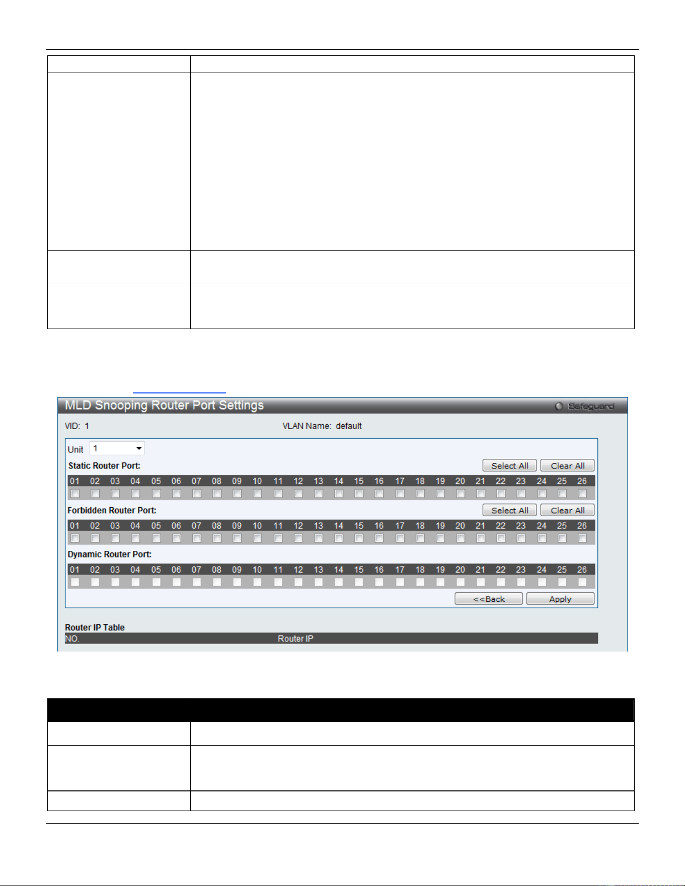
xStack® DGS-3420 Series Layer 2 Managed Stackable Gigabit Switch Web UI Reference Guide
141
by default.
Data Driven Learning
State
Specifies to enable or disable the data driven learning of a MLD snooping group. When
the data-driven learning is enabled for the VLAN, when the switch receives the IP
multicast traffic, on this VLAN, an MLD snooping group will be created. That is, the
learning of an entry is not activated by MLD membership registration, but activated by
the traffic. For an ordinary MLD snooping entry, the MLD protocol will take care the
aging out of the entry. For a data-driven entry, the entry can be specified not to be age
out or to be aged out by the aged timer. When the data driven learning is enabled, and
data driven table is not full, the multicast filtering mode for all ports are ignored. That is,
the multicast packets will be forwarded to router ports. If data driven learning table is
full, the multicast packets will be forwarded according to multicast filtering mode.
Note: If a data-driven group is created and MLD member ports are learned later, the
entry will become an ordinary MLD snooping entry. That is, the aging out mechanism
will follow the ordinary MLD snooping entry.
Data Driven Learning
Aged Out
Specifies to enable or disable the aging of the entry. This is disabled by default.
Version
Specify the version of MLD packet that will be sent by this port. If a MLD packet
received by the interface has a version higher than the specified version, this packet
will be forwarded from the router ports or VLAN flooding.
Click the Apply button to accept the changes made.
Click the <<Back button to discard the changes made and return to the previous page.
After clicking the Modify Router Port link, the following page will appear:
Figure 4-72 MLD Snooping Router Port Settings window
The fields that can be configured are described below:
Parameter Description
Unit
Select the unit you wish to configure.
Static Router Port
This section is used to designate a range of ports as being connected to multicast-
enabled routers. This will ensure that all packets with such a router as its destination
will reach the multicast-enabled router regardless of the protocol.
Forbidden Router Port
This section is used to designate a range of ports as being not connected to multicast-
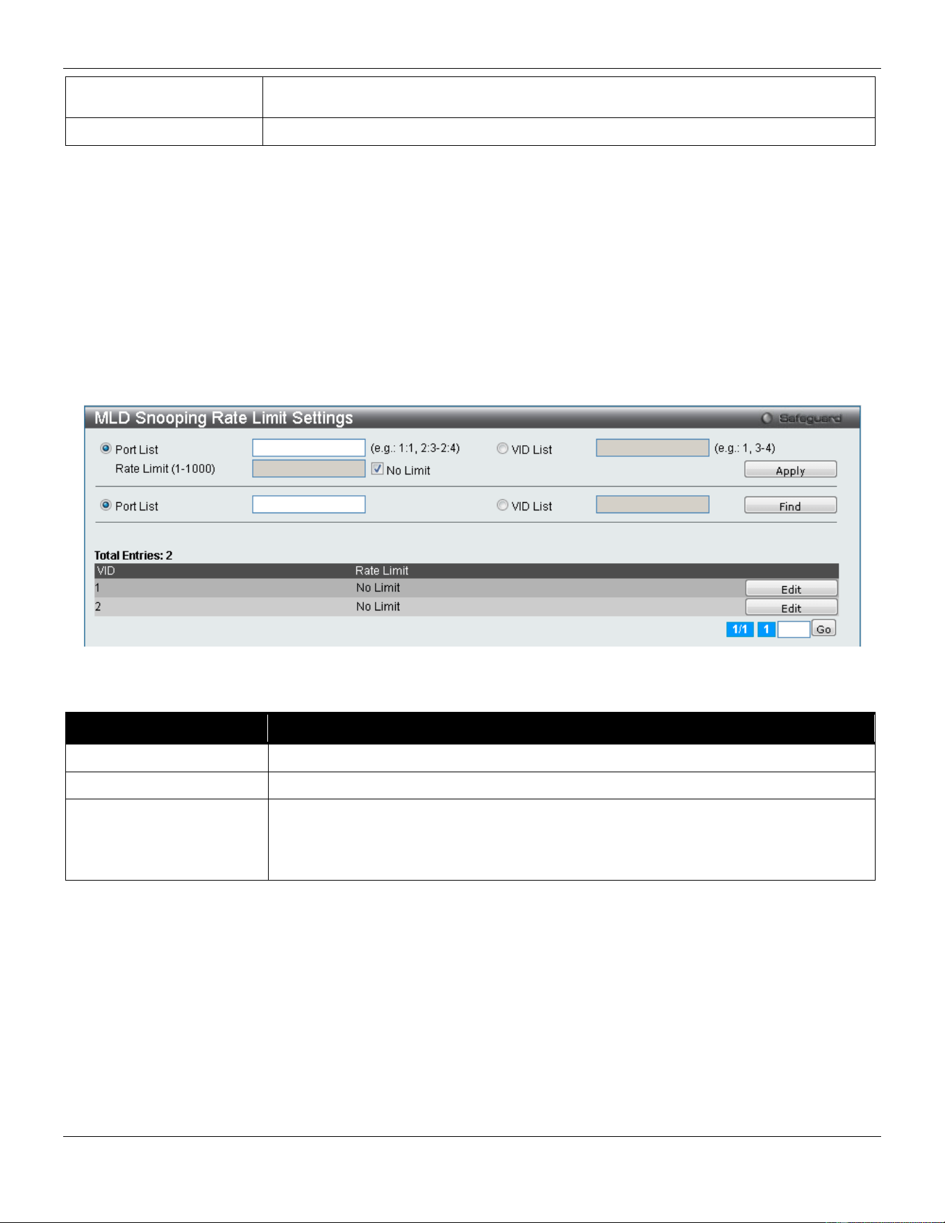
xStack® DGS-3420 Series Layer 2 Managed Stackable Gigabit Switch Web UI Reference Guide
142
enabled routers. This ensures that the forbidden router port will not propagate routing
packets out.
Dynamic Router Port
Displays router ports that have been dynamically configured.
Click the Select All button to select all the ports for configuration.
Click the Clear All button to unselect all the ports for configuration.
Click the Apply button to accept the changes made.
Click the <<Back button to discard the changes made and return to the previous page.
MLD Snooping Rate Limit Settings
Users can configure the rate limit of the MLD control packet that the switch can process on a specific port or VLAN in
this page.
To view the following window, click L2 Features > L2 Multicast Control > MLD Snooping > MLD Snooping Rate
Limit Settings, as show below:
Figure 4-73 MLD Snooping Rate Limit Settings window
The fields that can be configured are described below:
Parameter Description
Port List
Enter the Port List here.
VID List
Enter the VID List value here.
Rate Limit
Configure the rate limit of MLD control packet that the switch can process on a
specific port/VLAN. The rate is specified in packet per second. The packet that
exceeds the limited rate will be dropped. Selecting the No Limit option lifts the rate
limit requirement.
Click the Apply button to accept the changes made for each individual section.
Click the Find button to locate a specific entry based on the information entered.
Click the Edit button to re-configure the specific entry.
Enter a page number and click the Go button to navigate to a specific page when multiple pages exist.
MLD Snooping Static Group Settings
This page used to configure the MLD snooping multicast group static members.
To view the following window, click L2 Features > L2 Multicast Control > MLD Snooping > MLD Snooping Static
Group Settings, as show below:
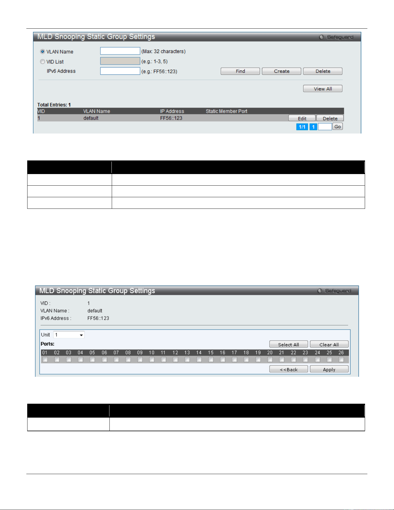
xStack® DGS-3420 Series Layer 2 Managed Stackable Gigabit Switch Web UI Reference Guide
143
Figure 4-74 MLD Snooping Static Group Settings window
The fields that can be configured are described below:
Parameter Description
VLAN Name
The name of the VLAN on which the static group resides.
VID List
The ID of the VLAN on which the static group resides.
IPv6 Address
Specify the multicast group IPv6 address.
Click the Find button to locate a specific entry based on the information entered.
Click the Create button to add a static group.
Click the Delete button to delete a static group.
Click the View All button to display all the existing entries.
Click the Edit button to re-configure the specific entry.
Enter a page number and click the Go button to navigate to a specific page when multiple pages exist.
After clicking the Edit button, the following page will appear:
Figure 4-75 MLD Snooping Static Group Settings – Edit window
The fields that can be configured are described below:
Parameter Description
Unit
Select the unit you wish to configure.
Click the Select All button to select all the ports for configuration.
Click the Clear All button to unselect all the ports for configuration.
Click the Apply button to accept the changes made.
Click the <<Back button to discard the changes made and return to the previous page.
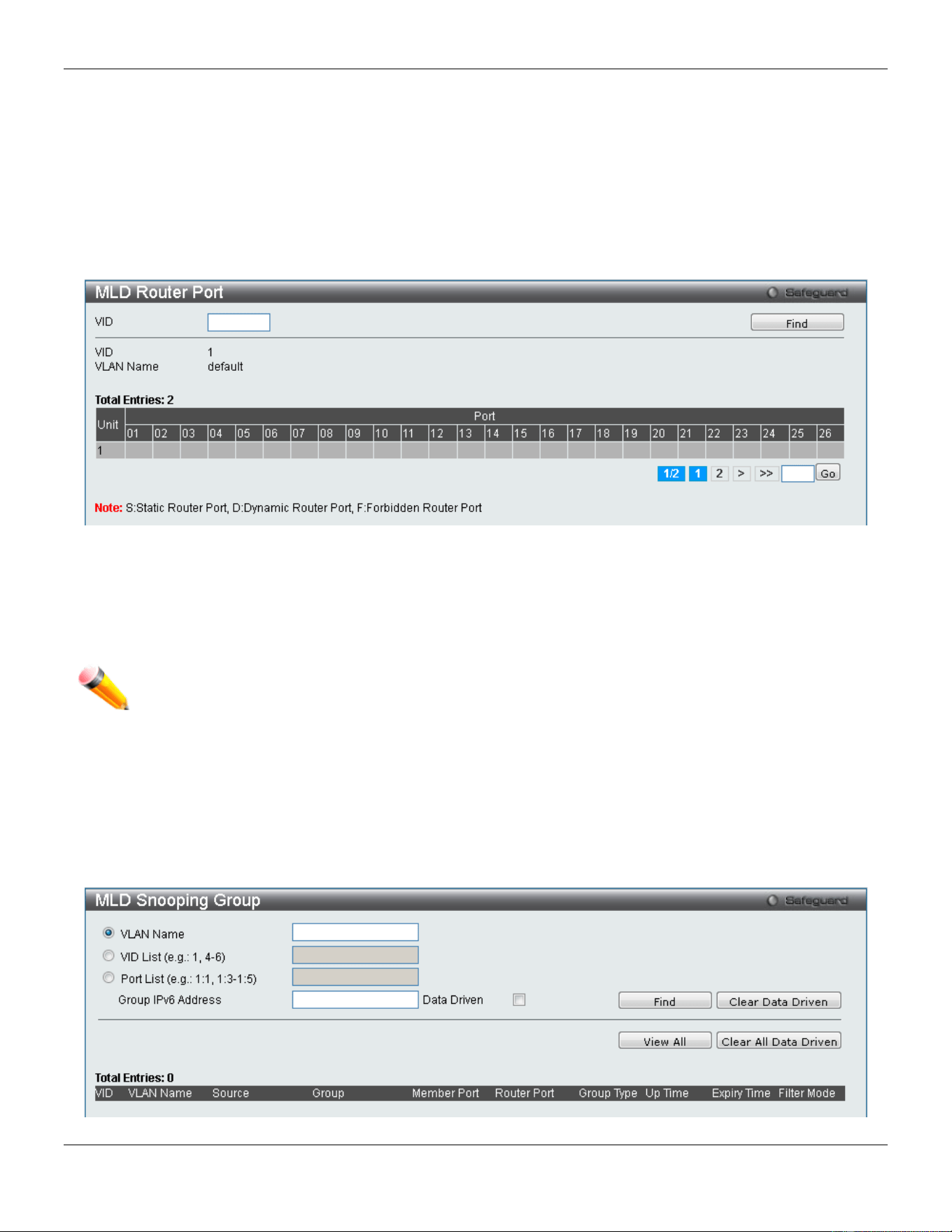
xStack® DGS-3420 Series Layer 2 Managed Stackable Gigabit Switch Web UI Reference Guide
144
MLD Router Port
Users can display which of the Switch’s ports are currently configured as router ports in IPv6. A router port configured
by a user (using the console or Web-based management interfaces) is displayed as a static router port, designated by
S. A router port that is dynamically configured by the Switch is designated by D, while a Forbidden port is designated
by F.
To view the following window, click L2 Features > L2 Multicast Control > MLD Snooping > MLD Router Port, as
show below:
Figure 4-76 MLD Router Port window
Enter a VID (VLAN ID) in the field at the top of the window.
Click the Find button to locate a specific entry based on the information entered.
Enter a page number and click the Go button to navigate to a specific page when multiple pages exist.
NOTE: The abbreviations used on this page are Static Router Port (S), Dynamic Router Port (D) and
Forbidden Router Port (F).
MLD Snooping Group
Users can view MLD Snooping Groups present on the Switch. MLD Snooping is an IPv6 function comparable to IGMP
Snooping for IPv4.
To view the following window, click L2 Features > L2 Multicast Control > MLD Snooping > MLD Snooping Group,
as show below:
Figure 4-77 MLD Snooping Group window
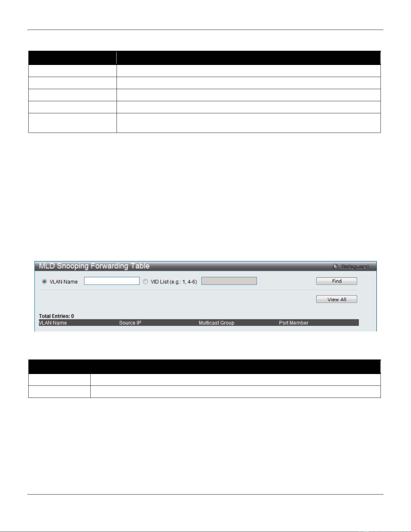
xStack® DGS-3420 Series Layer 2 Managed Stackable Gigabit Switch Web UI Reference Guide
145
The fields that can be configured are described below:
Parameter Description
VLAN Name
Click the radio button and enter the VLAN name of the multicast group.
VID List
Click the radio button and enter a VLAN list of the multicast group.
Port List
Specify the port number(s) used to find a multicast group.
Group IPv6 Address
Enter the group IPv6 address used here.
Data Driven
Specifies whether to enable or disable the data driven learning of an MLD snooping
group. This is enabled by default.
Click the Find button to locate a specific entry based on the information entered.
Click the View All button to display all the existing entries.
Click the Clear Data Driven button to clear data driven information for the specified entry.
Click the Clear All Data Driven button to clear data driven information for all entries.
MLD Snooping Forwarding Table
This page displays the switch’s current MLD snooping forwarding table. It provides an easy way for user to check the
list of ports that the multicast group comes from and specific sources that it will be forwarded to. The packet comes
from the source VLAN. They will be forwarded to the forwarding VLAN. The MLD snooping further restricts the
forwarding ports.
To view the following window, click L2 Features > L2 Multicast Control > MLD Snooping > MLD Snooping
Forwarding Table, as show below:
Figure 4-78 MLD Snooping Forwarding Table window
The fields that can be configured are described below:
Parameter Description
VLAN Name
The name of the VLAN for which you want to view MLD snooping forwarding table information.
VID List
The ID of the VLAN for which you want to view MLD snooping forwarding table information.
Click the Find button to locate a specific entry based on the information entered.
Click the View All button to display all the existing entries.
MLD Snooping Counter
This page displays the statistics counter for MLD protocol packets that are received by the switch since MLD Snooping
is enabled.
To view the following window, click L2 Features > L2 Multicast Control > MLD Snooping > MLD Snooping Counter,
as show below:
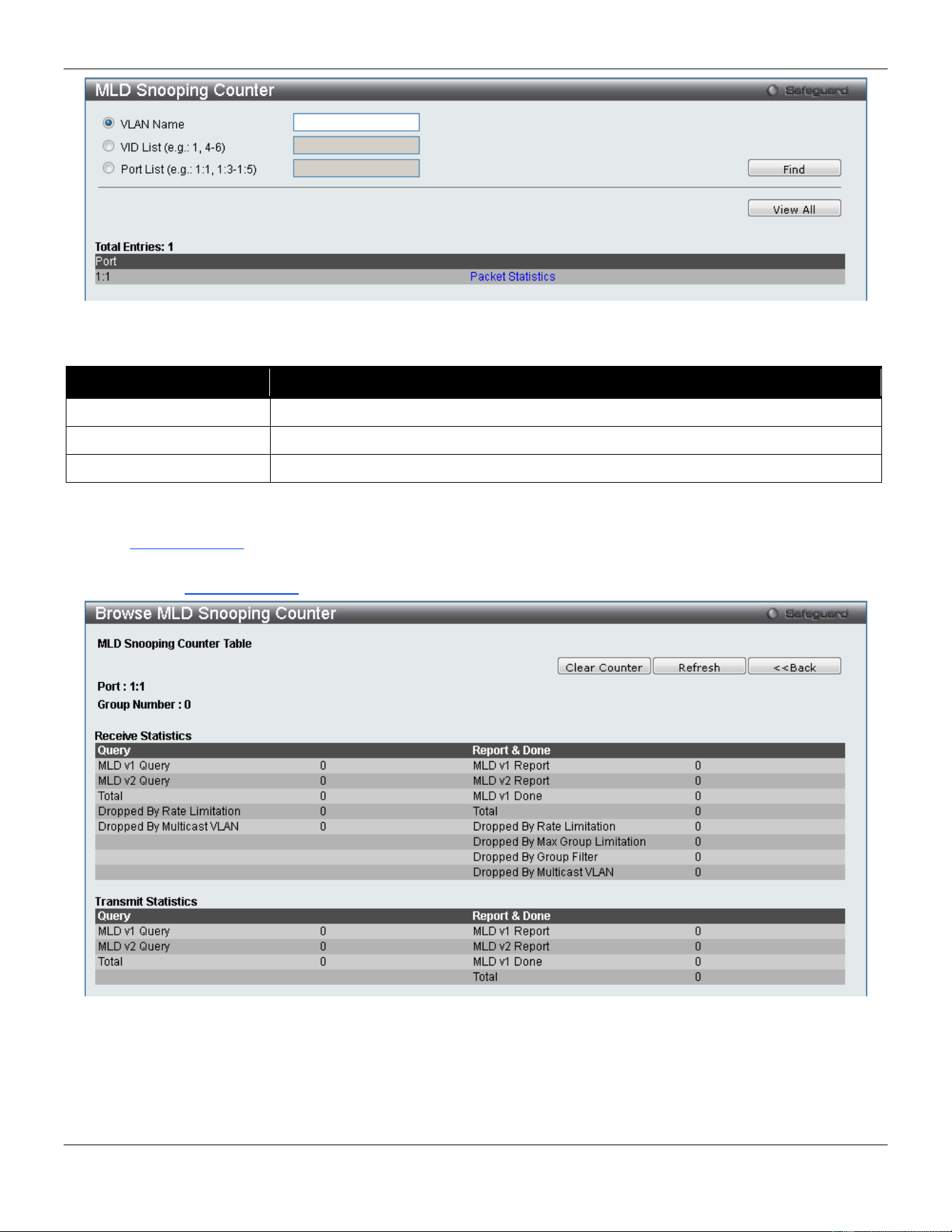
xStack® DGS-3420 Series Layer 2 Managed Stackable Gigabit Switch Web UI Reference Guide
146
Figure 4-79 MLD Snooping Counter window
The fields that can be configured are described below:
Parameter Description
VLAN Name
Specify a VLAN name to be displayed.
VID List
Specify a list of VLANs to be displayed.
Port List
Specify a list of ports to be displayed.
Click the Find button to locate a specific entry based on the information entered.
Click the View All button to display all the existing entries.
Click the Packet Statistics link to view the MLD Snooping Counter Settings for the specific entry.
After clicking the Packet Statistics link, the following page will appear:
Figure 4-80 Browse MLD Snooping Counter window
Click the Clear Counter button to clear all the information displayed in the fields.
Click the Refresh button to refresh the display table so that new information will appear.
Click the <<Back button to return to the previous page.
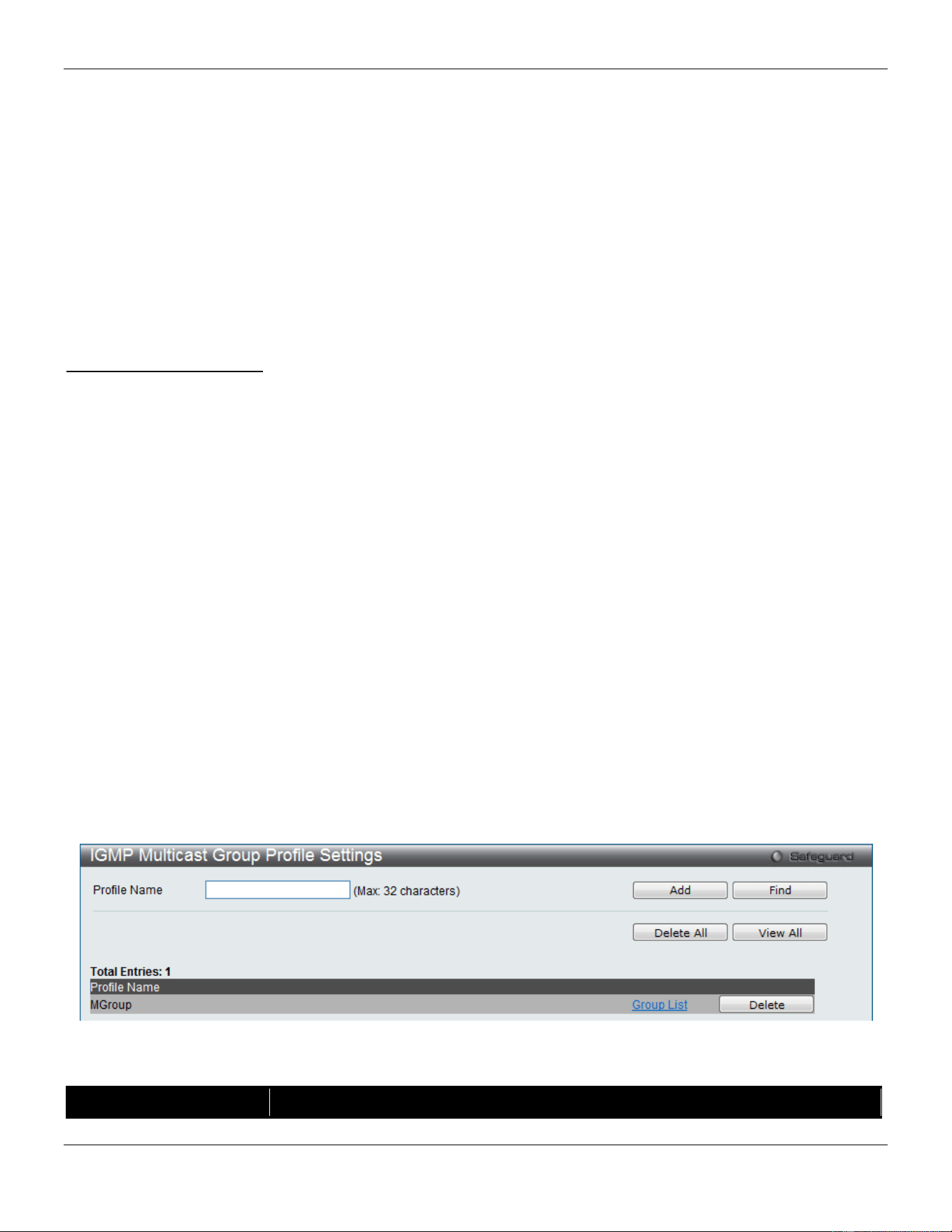
xStack® DGS-3420 Series Layer 2 Managed Stackable Gigabit Switch Web UI Reference Guide
147
Multicast VLAN
In a switching environment, multiple VLANs may exist. Every time a multicast query passes through the Switch, the
switch must forward separate different copies of the data to each VLAN on the system, which, in turn, increases data
traffic and may clog up the traffic path. To lighten the traffic load, multicast VLANs may be incorporated. These
multicast VLANs will allow the Switch to forward this multicast traffic as one copy to recipients of the multicast VLAN,
instead of multiple copies.
Regardless of other normal VLANs that are incorporated on the Switch, users may add any ports to the multicast VLAN
where they wish multicast traffic to be sent. Users are to set up a source port, where the multicast traffic is entering the
switch, and then set the ports where the incoming multicast traffic is to be sent. The source port cannot be a recipient
port and if configured to do so, will cause error messages to be produced by the switch. Once properly configured, the
stream of multicast data will be relayed to the receiver ports in a much more timely and reliable fashion.
Restrictions and Provisos:
The Multicast VLAN feature of this Switch does have some restrictions and limitations, such as:
1. Multicast VLANs can be implemented on edge and non-edge switches.
2. Member ports and source ports can be used in multiple Multicast VLANs. But member ports and source ports
cannot be the same port in a specific Multicast VLAN.
3. The Multicast VLAN is exclusive with normal 802.1q VLANs, which means that VLAN IDs (VIDs) and VLAN
Names of 802.1q VLANs and Multicast VLANs cannot be the same. Once a VID or VLAN Name is chosen for
any VLAN, it cannot be used for any other VLAN.
4. The normal display of configured VLANs will not display configured Multicast VLANs.
5. Once a Multicast VLAN is enabled, the corresponding IGMP snooping state or MLD snooping state of this
VLAN will also be enabled. Users cannot disable the IGMP snooping and MLD snooping feature for an enabled
Multicast VLAN.
6. One IP multicast address cannot be added to multiple Multicast VLANs, yet multiple Ranges can be added to
one Multicast VLAN.
IGMP Multicast Group Profile Settings
Users can add a profile to which multicast address reports are to be received on specified ports on the Switch. This
function will therefore limit the number of reports received and the number of multicast groups configured on the Switch.
The user may set an IP Multicast address or range of IP Multicast addresses to accept reports (Permit) or deny reports
(Deny) coming into the specified switch ports.
To view the following window, click L2 Features > L2 Multicast Control > Multicast VLAN > IGMP Multicast Group
Profile Settings, as show below:
Figure 4-81 IGMP Multicast Group Profile Settings window
The fields that can be configured are described below:
Parameter Description
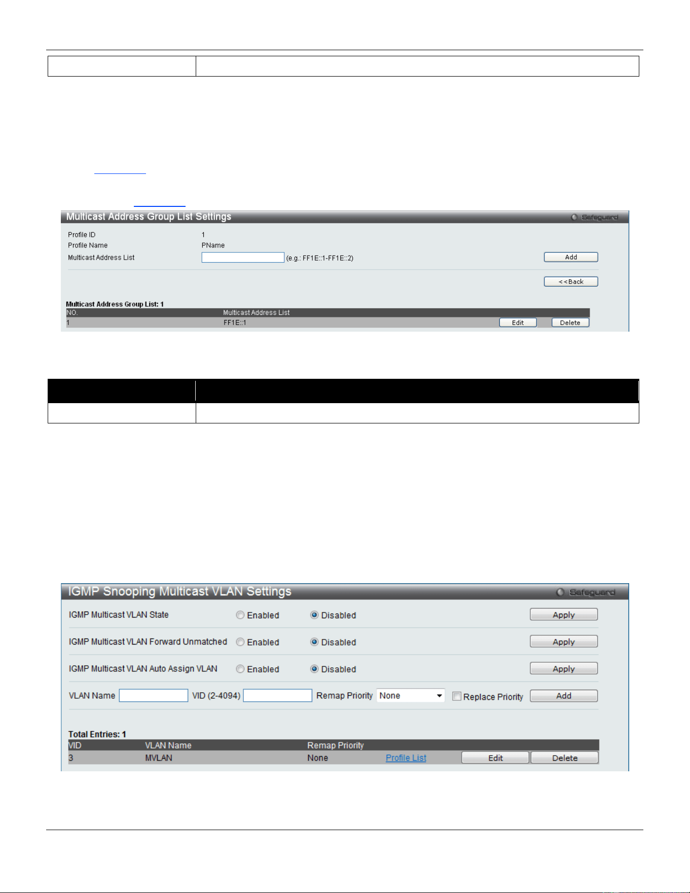
xStack® DGS-3420 Series Layer 2 Managed Stackable Gigabit Switch Web UI Reference Guide
148
Profile Name
Enter a name for the IP Multicast Profile.
Click the Add button to add a new entry based on the information entered.
Click the Find button to locate a specific entry based on the information entered.
Click the Delete All button to remove all the entries listed.
Click the View All button to display all the existing entries.
Click the Delete button to remove the corresponding entry.
Click the Group List link to configure the Multicast Group Profile Address Settings for the specific entry.
After clicking the Group List link, the following page will appear:
Figure 4-82 Multicast Group Profile Multicast Address Settings window
The fields that can be configured are described below:
Parameter Description
Multicast Address List
Enter the multicast address list value.
Click the Add button to add a new entry based on the information entered.
Click the <<Back button to discard the changes made and return to the previous page.
Click the Delete button to remove the corresponding entry.
IGMP Snooping Multicast VLAN Settings
On this page the user can configure the IGMP snooping multicast VLAN parameters.
To view the following window, click L2 Features > L2 Multicast Control > Multicast VLAN > IGMP Snooping
Multicast VLAN Settings, as show below:
Figure 4-83 IGMP Snooping Multicast VLAN Settings window
The fields that can be configured are described below:
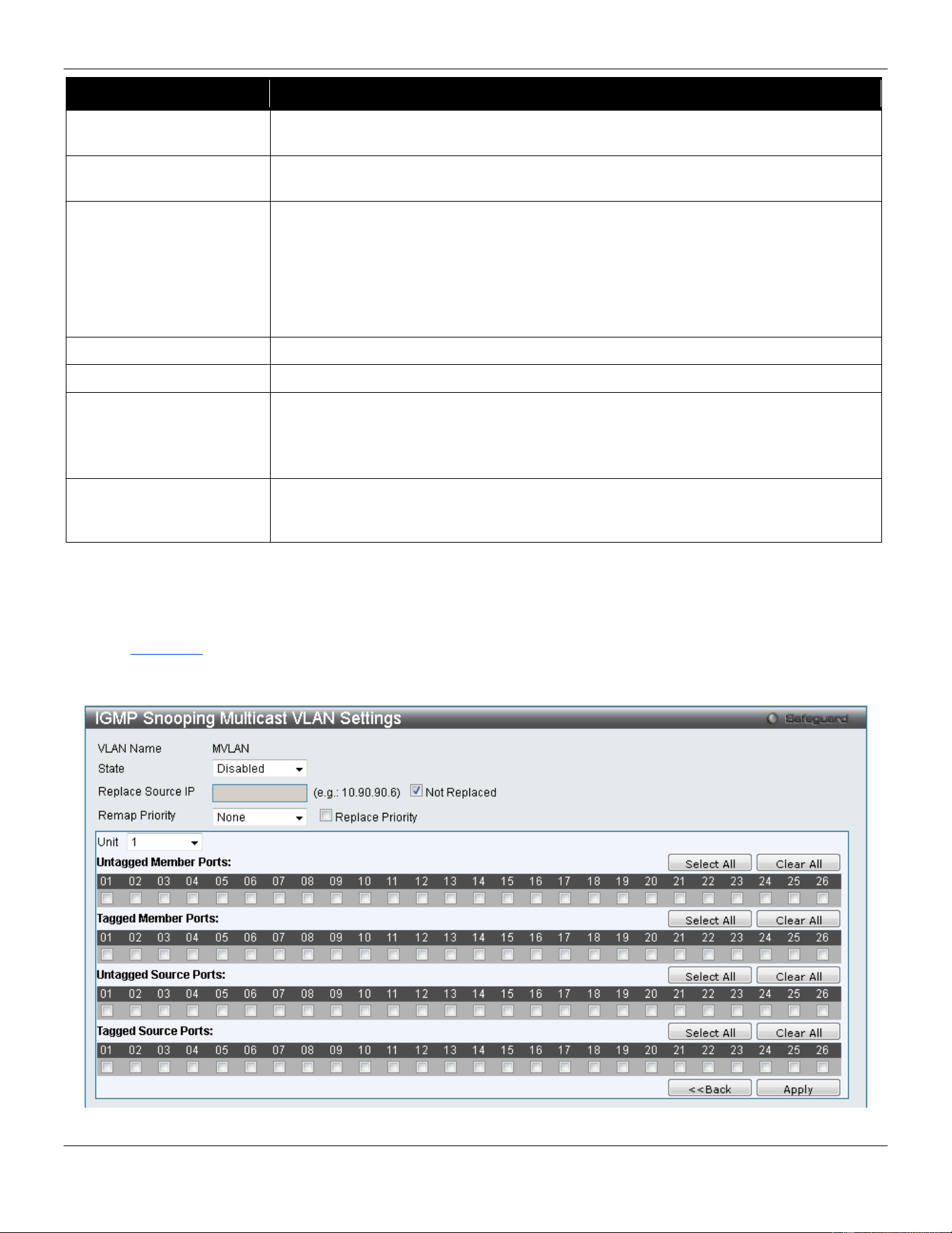
xStack® DGS-3420 Series Layer 2 Managed Stackable Gigabit Switch Web UI Reference Guide
149
Parameter Description
IGMP Multicast VLAN
State
Click the radio buttons to enable or disable the IGMP Multicast VLAN state.
IGMP Multicast VLAN
Forward Unmatched
Click the radio buttons to enable or disable the IGMP Multicast VLAN Forwarding
state.
IGMP Multicast VLAN
Auto Assign VLAN
Specifies to enable or disable the assignment of IGMP control packets to the right
Multicast VLAN. If auto assign VLAN is enabled, the Switch will check for group
matching with multicast VLAN profiles of which the ingress port belongs to. If there is
a match, the result is "in profile" and the matching multicast VLAN will be set as a
packet VLAN. If this function is disabled, the Switch will do VID checking, and
afterwards, if the group does not match the current profile binding, the Switch will drop
this packet.
VLAN Name
Enter the VLAN Name used.
VID (2-4094)
Enter the VID used.
Remap Priority 0-7 – The remap priority value (0 to 7) to be associated with the data traffic to be
forwarded on the multicast VLAN.
None – If None is specified, the packet’s original priority is used. The default setting is
None.
Replace Priority
Tick the check box to specify that the packet’s priority will be changed by the Switch,
based on the remap priority. This flag will only take effect when the remap priority is
set.
Click the Apply button to accept the changes made for each individual section.
Click the Add button to add a new entry based on the information entered.
Click the Edit button to configure the IGMP Snooping Multicast VLAN Settings for the specific entry.
Click the Delete button to remove the specific entry.
Click the Profile List link to configure the IGMP Snooping Multicast VLAN Settings for the specific entry.
After clicking the Edit button, the following page will appear:
Figure 4-84 IGMP Snooping Multicast VLAN Settings – Edit window
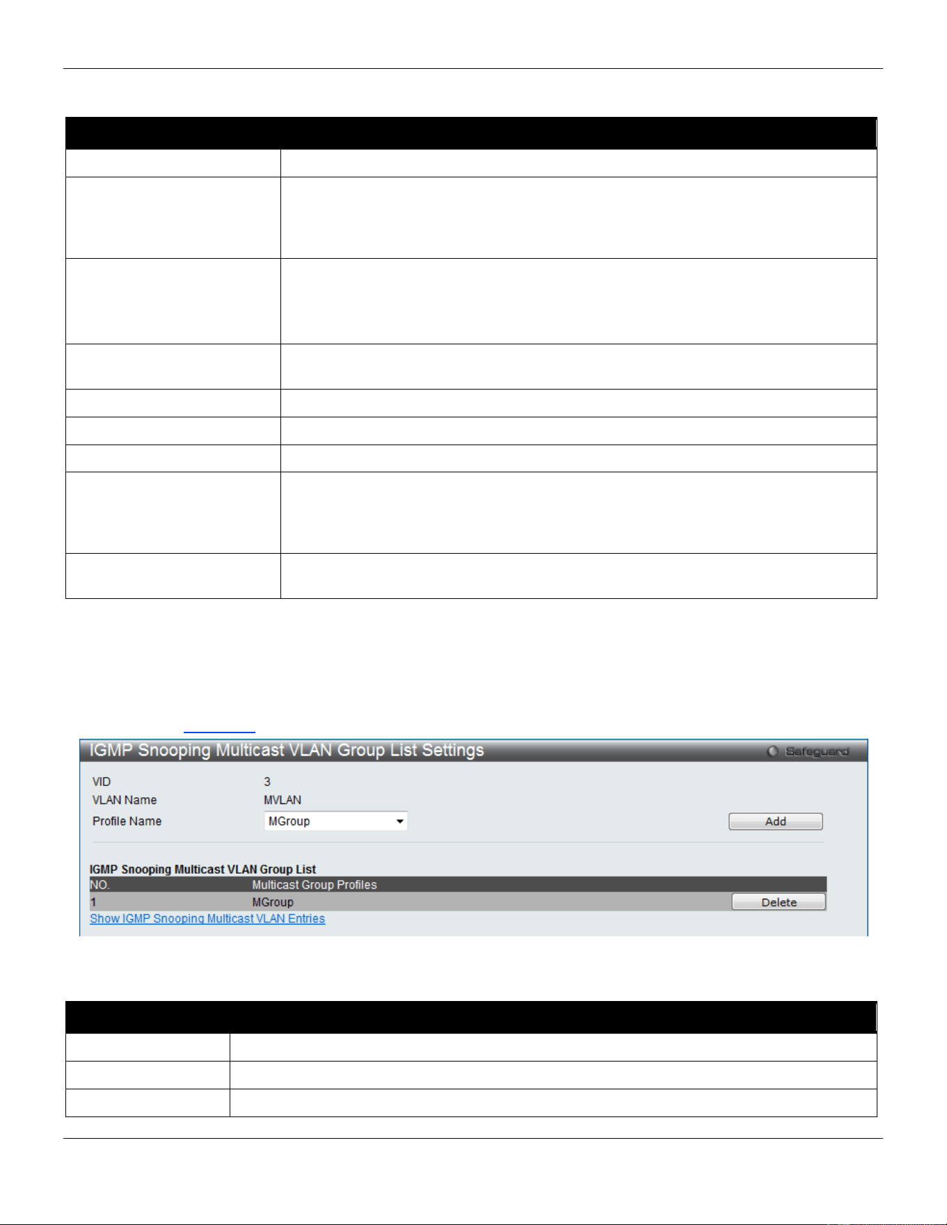
xStack® DGS-3420 Series Layer 2 Managed Stackable Gigabit Switch Web UI Reference Guide
150
The fields that can be configured are described below:
Parameter Description
State
Use the drop-down menu to enable or disable the state.
Replace Source IP
With the IGMP snooping function, the IGMP report packet sent by the host will be
forwarded to the source port. Before forwarding of the packet, the source IP address
in the join packet needs to be replaced by this IP address. If none is specified, the
source IP address will use zero IP address.
Remap Priority 0-7 – The remap priority value (0 to 7) to be associated with the data traffic to be
forwarded on the multicast VLAN.
None – If None is specified, the packet’s original priority is used. The default setting
is None.
Replace Priority
Specify that the packet’s priority will be changed by the switch, based on the remap
priority. This flag will only take effect when the remap priority is set.
Unit
Select the unit you wish to configure.
Untagged Member Ports
Specify the untagged member port of the multicast VLAN.
Tagged Member Ports
Specify the tagged member port of the multicast VLAN.
Untagged Source Ports
Specify the untagged source port where the multicast traffic is entering the Switch.
The PVID of the untagged source port is automatically changed to the multicast
VLAN. Source ports must be either tagged or untagged for any single multicast
VLAN, i.e. both types cannot be members of the same multicast VLAN.
Tagged Source Ports
Specify the source port or range of source ports as tagged members of the multicast
VLAN.
Click the Select All button to select all the ports for configuration.
Click the Clear All button to unselect all the ports for configuration.
Click the Apply button to accept the changes made.
Click the <<Back button to discard the changes made and return to the previous page.
After clicking the Profile List link, the following page will appear:
Figure 4-85 IGMP Snooping Multicast VLAN Group List Settings window
The fields that can be configured or displayed are described below:
Parameter Description
VID
Display the VLAN ID.
VLAN Name
Display the VLAN name.
Profile Name
Use the drop-down menu to select the IGMP Snooping Multicast VLAN Group Profile name.
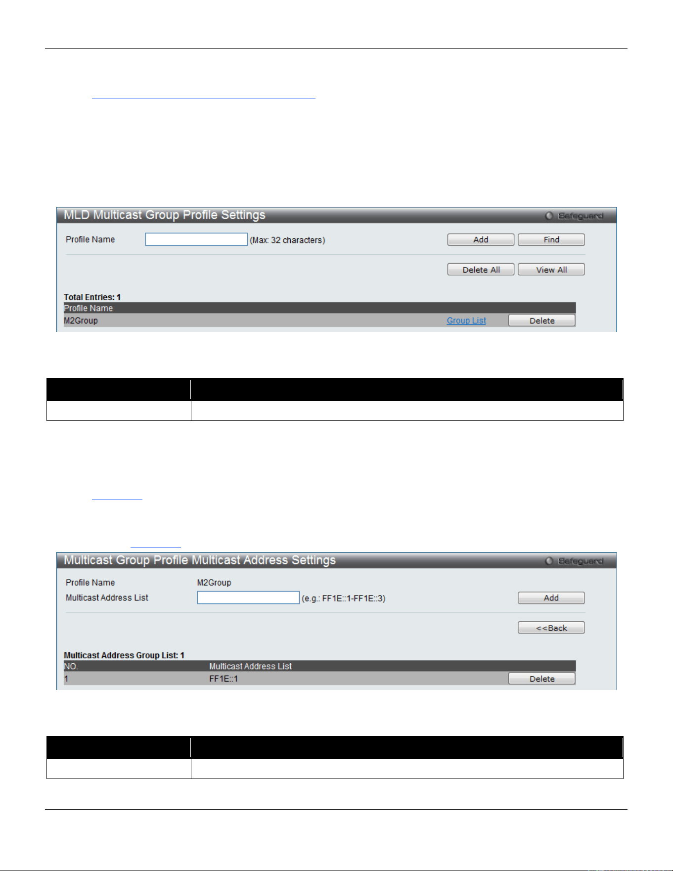
xStack® DGS-3420 Series Layer 2 Managed Stackable Gigabit Switch Web UI Reference Guide
151
Click the Add button to add a new entry based on the information entered.
Click the Delete button to remove the specific entry.
Click the Show IGMP Snooping Multicast VLAN Entries link to view the IGMP Snooping Multicast VLAN Settings.
MLD Multicast Group Profile Settings
Users can add, delete, or configure the MLD multicast group profile on this page.
To view the following window, click L2 Features > L2 Multicast Control > Multicast VLAN > MLD Multicast Group
Profile Settings, as show below:
Figure 4-86 MLD Multicast Group Profile Settings window
The fields that can be configured are described below:
Parameter Description
Profile Name
Enter the MLD Multicast Group Profile name.
Click the Add button to add a new entry based on the information entered.
Click the Find button to locate a specific entry based on the information entered.
Click the Delete All button to remove all the entries listed.
Click the View All button to display all the existing entries.
Click the Group List link to configure the Multicast Group Profile Multicast Address Settings for the specific entry.
Click the Delete button to remove the specific entry.
After clicking the Group List link, the following page will appear:
Figure 4-87 Multicast Group Profile Multicast Address Settings window
The fields that can be configured are described below:
Parameter Description
Multicast Address List
Enter the multicast address list.
Click the Add button to add a new entry based on the information entered.
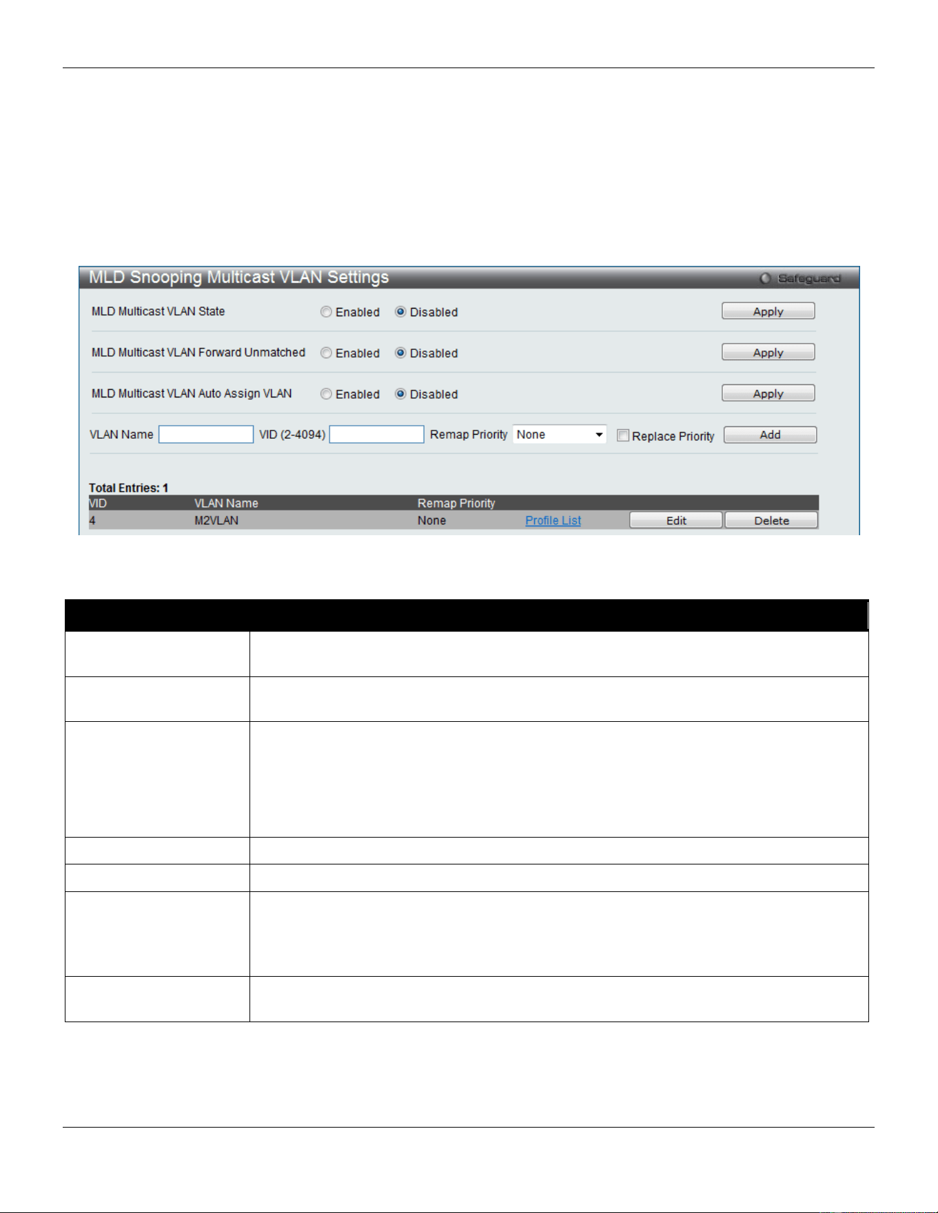
xStack® DGS-3420 Series Layer 2 Managed Stackable Gigabit Switch Web UI Reference Guide
152
Click the <<Back button to discard the changes made and return to the previous page.
Click the Delete button to remove the specific entry.
MLD Snooping Multicast VLAN Settings
Users can add, delete, or configure the MLD snooping multicast VLAN on this page.
To view the following window, click L2 Features > L2 Multicast Control > Multicast VLAN > MLD Snooping
Multicast VLAN Settings, as show below:
Figure 4-88 MLD Snooping Multicast VLAN Settings window
The fields that can be configured are described below:
Parameter Description
MLD Multicast VLAN
State
Click the radio buttons to enable or disable the MLD multicast VLAN state.
MLD Multicast VLAN
Forward Unmatched
Click the radio buttons to can enable or disable the MLD multicast VLAN Forward
Unmatched state.
MLD Multicast VLAN
Auto Assign VLAN
Specifies to enable the auto assignment of MLD control packets to the right Multicast
VLAN. If auto assign VLAN is enabled, the Switch would check for group matching in the
profiles of all multicast VLANs to which the ingress port belongs to. If there is a match,
the result is "in profile" and the matching multicast VLAN will be set as the packet VLAN.
If this function is disabled, the Switch will do VID checking first. If the group does not
match the current profile binding to the multicast VLAN, the Switch will drop this packet.
VLAN Name
Enter the VLAN name used.
VID
Enter the VID value used.
Remap Priority
The user can select this option to enable the Remap Priority feature.
Specify the remap priority (0 to 7) to be associated with the data traffic to be forwarded
on the multicast VLAN. If None is specified, the packet’s original priority will be used.
The default setting is None.
Replace Priority
Tick the check box to specify that the packet’s priority will be changed by the switch,
based on the remap priority. This flag will only take effect when the remap priority is set.
Click the Apply button to accept the changes made for each individual section.
Click the Add button to add a new entry based on the information entered.
Click the Edit button to configure the MLD Snooping Multicast VLAN Settings for the specific entry.
Click the Delete button to remove the specific entry.
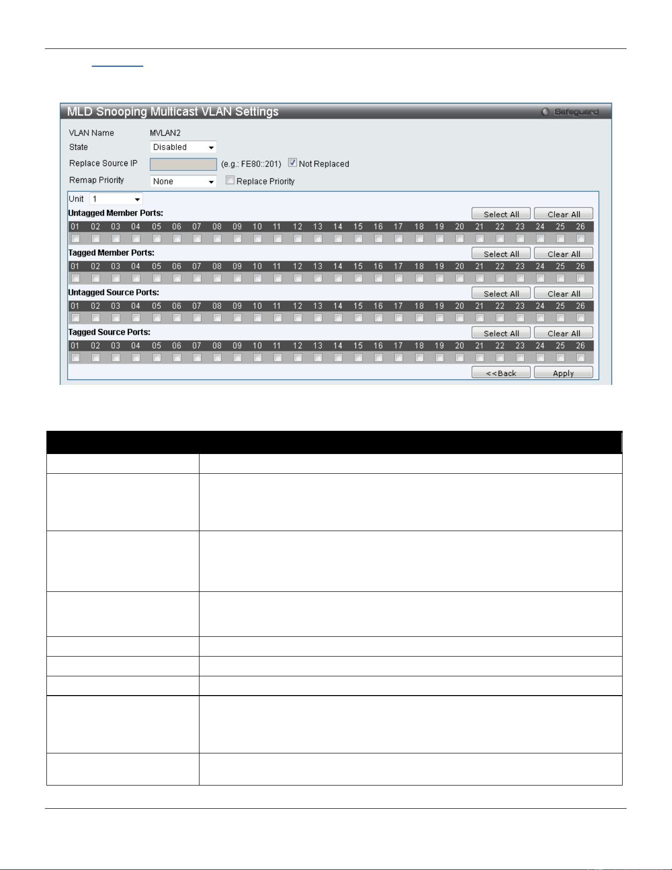
xStack® DGS-3420 Series Layer 2 Managed Stackable Gigabit Switch Web UI Reference Guide
153
Click the Profile List link to configure the MLD Snooping Multicast VLAN Settings for the specific entry.
After clicking the Edit button, the following page will appear:
Figure 4-89 MLD Snooping Multicast VLAN Settings – Edit window
The fields that can be configured are described below:
Parameter Description
State
Use the drop-down menu to enable or disable the state.
Replace Source IP
With the MLD snooping function, the MLD report packet sent by the host will be
forwarded to the source port. Before forwarding of the packet, the source IP address
in the join packet needs to be replaced by this IP address. If none is specified, the
source IP address will use zero IP address.
Remap Priority 0-7 – The remap priority value (0 to 7) to be associated with the data traffic to be
forwarded on the multicast VLAN.
None – If None is specified, the packet’s original priority is used. The default setting
is None.
Replace Priority
Tick the check box to specify that the packet’s priority will be changed by the switch,
based on the remap priority. This flag will only take effect when the remap priority is
set.
Unit
Select the unit you wish to configure.
Untagged Member Ports
Specify the untagged member port of the multicast VLAN.
Tagged Member Ports
Specify the tagged member port of the multicast VLAN.
Untagged Source Ports
Specify the untagged source port where the multicast traffic is entering the Switch.
The PVID of the untagged source port is automatically changed to the multicast
VLAN. Source ports must be either tagged or untagged for any single multicast
VLAN, i.e. both types cannot be members of the same multicast VLAN.
Tagged Source Ports
Specify the source port or range of source ports as tagged members of the multicast
VLAN.
Click the Select All button to select all the ports for configuration.
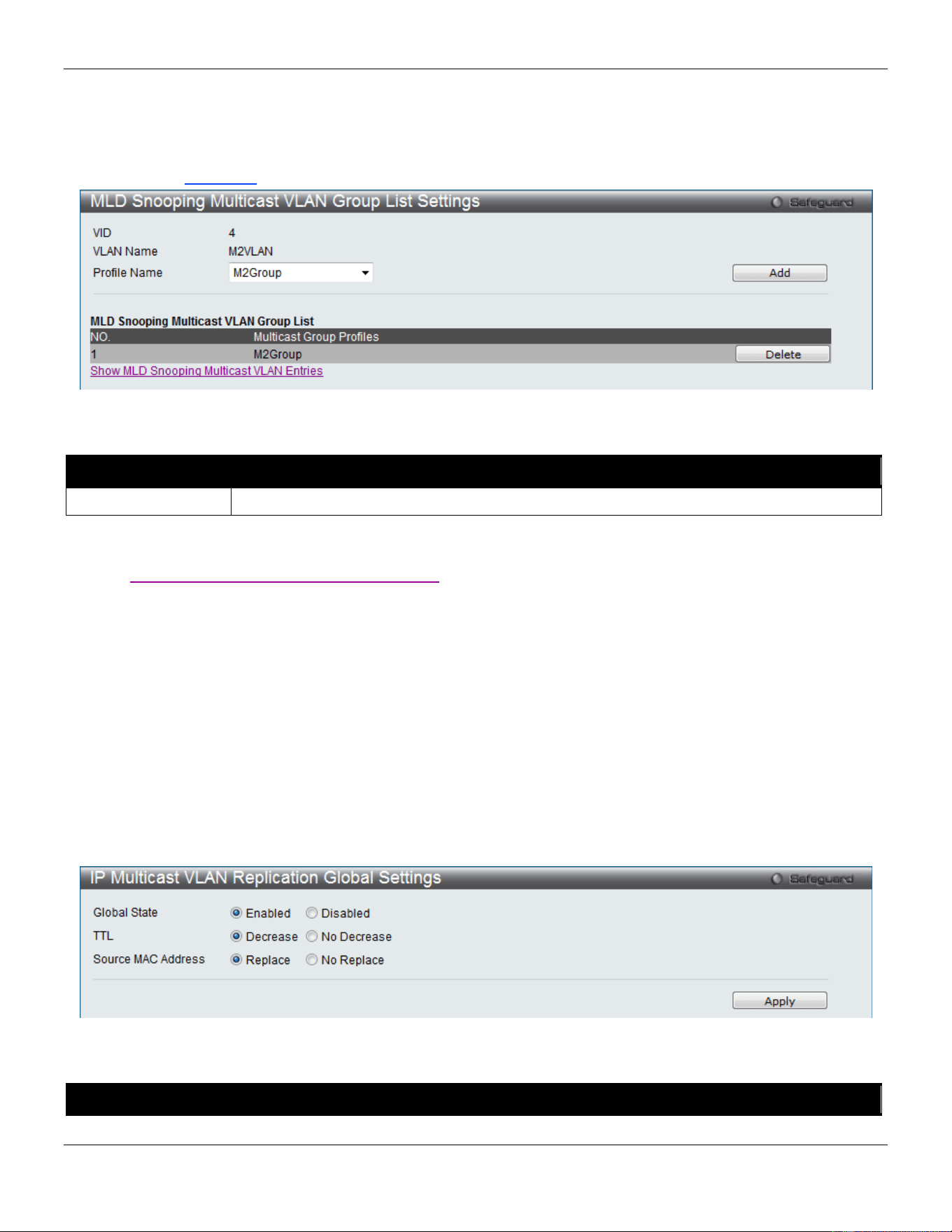
xStack® DGS-3420 Series Layer 2 Managed Stackable Gigabit Switch Web UI Reference Guide
154
Click the Clear All button to unselect all the ports for configuration.
Click the Apply button to accept the changes made.
Click the <<Back button to discard the changes made and return to the previous page.
After clicking the Profile List link, the following page will appear:
Figure 4-90 MLD Snooping Multicast VLAN Group List Settings window
The fields that can be configured are described below:
Parameter Description
Profile Name
Use the drop-down menu to select the MLD Snooping Multicast VLAN Group Profile name.
Click the Add button to add a new entry based on the information entered.
Click the Delete button to remove the specific entry.
Click the Show MLD Snooping Multicast VLAN Entries link to view the MLD Snooping Multicast VLAN Settings.
IP Multicast VLAN Replication
Generally, multicast data cannot be forwarded across VLANs if the switch doesn’t support any multicast routing
protocol. IP Multicast VLAN Replication can achieve this, without any multicast protocol being supported. Users need
to configure the desired source traffic and corresponding outgoing members.
IP Multicast VLAN Replication Global Settings
On this page the user can configure the IP multicast VLAN replication parameters.
To view the following window, click L2 Features > L2 Multicast Control > IP Multicast VLAN Replication > IP
Multicast VLAN Replication Global Settings, as show below:
Figure 4-91 IP Multicast VLAN Replication Global Settings window
The fields that can be configured are described below:
Parameter Description
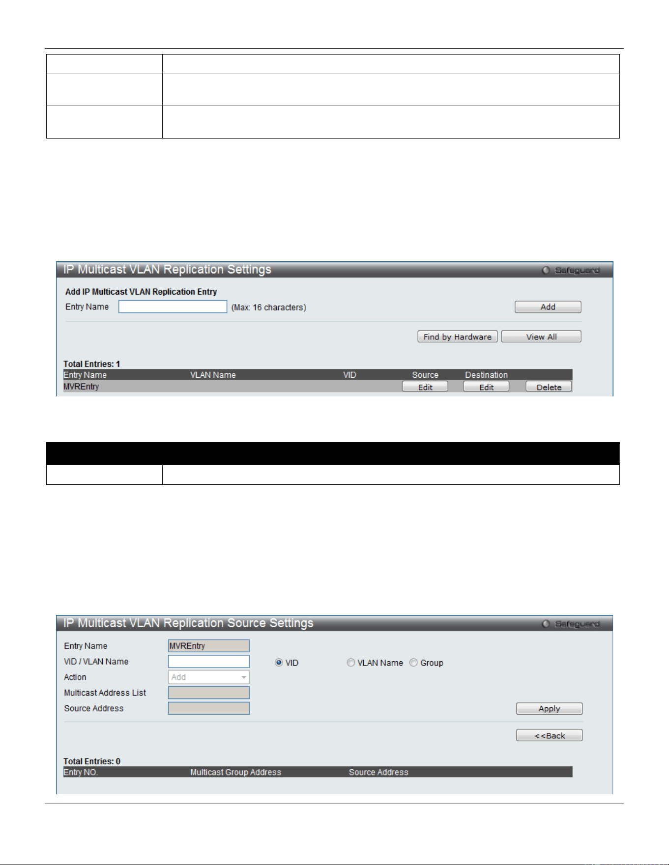
xStack® DGS-3420 Series Layer 2 Managed Stackable Gigabit Switch Web UI Reference Guide
155
Global State
Here the user can enable or disable the global state feature.
TTL
Here the user can select to decrease or no decrease the Time to live (TTL) value in the
packets.
Source MAC
Address
Here the user can select to replace or not to replace the Source MAC Address of the
packet.
Click the Apply button to accept the changes made.
IP Multicast VLAN Replication Settings
On this page the user can add and view the IP multicast VLAN replication table.
To view the following window, click L2 Features > L2 Multicast Control > IP Multicast VLAN Replication > IP
Multicast VLAN Replication Settings, as show below:
Figure 4-92 IP Multicast VLAN Replication Settings window
The fields that can be configured are described below:
Parameter Description
Entry Name
Here the user can enter a Multicast VLAN Replication entry name.
Click the Add button to add a new entry based on the information entered.
Click the Find by Hardware the find an entry based on the hardware.
Click the View All button to display all the existing entries.
Click the Edit button under Source to re-configure the specific entry.
Click the Edit button under Destination to re-configure the specific entry.
Click the Delete button to remove the specific entry.
After clicking the Edit button under Source, the following page will appear:
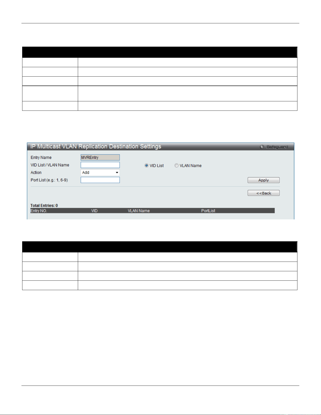
xStack® DGS-3420 Series Layer 2 Managed Stackable Gigabit Switch Web UI Reference Guide
156
Figure 4-93 IP Multicast VLAN Replication Settings window (Edit Source)
The fields that can be configured are described below:
Parameter Description
Entry Name
Here the IP Multicast VLAN Replication Source entry name will be displayed.
VID / VLAN Name
Here the user can choose to enter a VLAN Name, VID value or Group value.
Action
Here the user can select the action to be taken.
Multicast Address
List
Here the user can enter the multicast address list.
Source Address
Here the user can enter the source address.
Click the Apply button to accept the changes made.
Click the <<Back button to discard the changes made and return to the previous page.
After clicking the Edit button under Destination, the following page will appear:
Figure 4-94 IP Multicast VLAN Replication Settings window (Edit Destination)
The fields that can be configured are described below:
Parameter Description
Entry Name
Here the IP Multicast VLAN Replication Destination entry name will be displayed.
VID / VLAN Name
Here the user can choose to enter a VLAN Name, VID value or Group value.
Action
Here the user can select the action to be taken.
Port List
Here the user can enter the port list.
Click the Apply button to accept the changes made.
Click the <<Back button to discard the changes made and return to the previous page.
Multicast Filtering
IPv4 Multicast Filtering
IPv4 Multicast Profile Settings
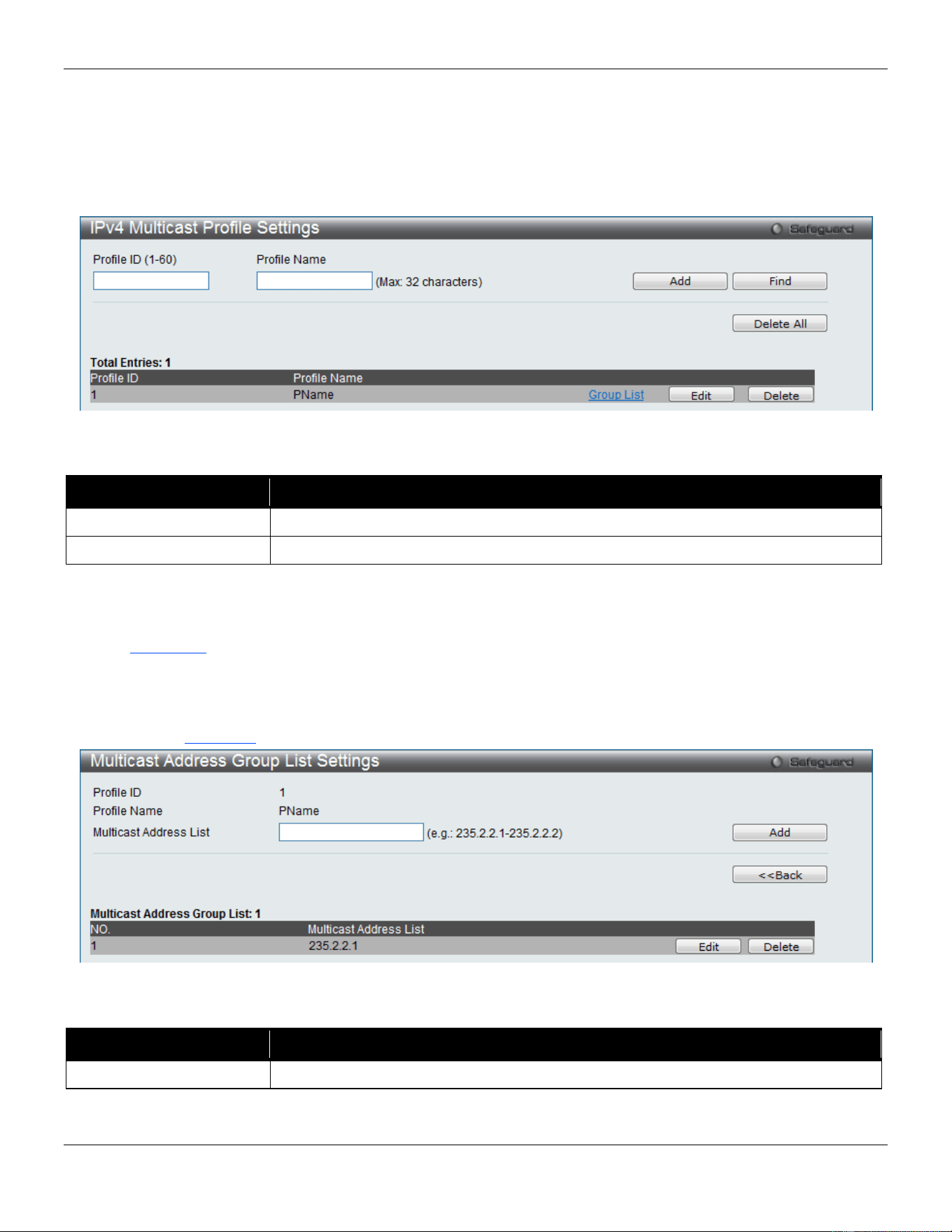
xStack® DGS-3420 Series Layer 2 Managed Stackable Gigabit Switch Web UI Reference Guide
157
Users can add a profile to which multicast address(s) reports are to be received on specified ports on the Switch. This
function will therefore limit the number of reports received and the number of multicast groups configured on the Switch.
The user may set an IPv4 Multicast address or range of IPv4 Multicast addresses to accept reports (Permit) or deny
reports (Deny) coming into the specified switch ports.
To view the following window, click L2 Features > Multicast Filtering > IPv4 Multicast Filtering > IPv4 Multicast
Profile Settings, as show below:
Figure 4-95 IPv4 Multicast Profile Settings window
The fields that can be configured are described below:
Parameter Description
Profile ID (1-60)
Enter a Profile ID between 1 and 60.
Profile Name
Enter a name for the IP Multicast Profile.
Click the Add button to add a new entry based on the information entered.
Click the Find button to locate a specific entry based on the information entered.
Click the Delete All button to remove all the entries listed.
Click the Group List link to configure the multicast address group list settings for the specific entry.
Click the Edit button to re-configure the specific entry.
Click the Delete button to remove the specific entry.
After clicking the Group List link, the following page will appear:
Figure 4-96 Multicast Address Group List Settings window
The fields that can be configured are described below:
Parameter Description
Multicast Address List
Enter the multicast address list here.
Click the Add button to add a new entry based on the information entered.
Click the <<Back button to discard the changes made and return to the previous page.
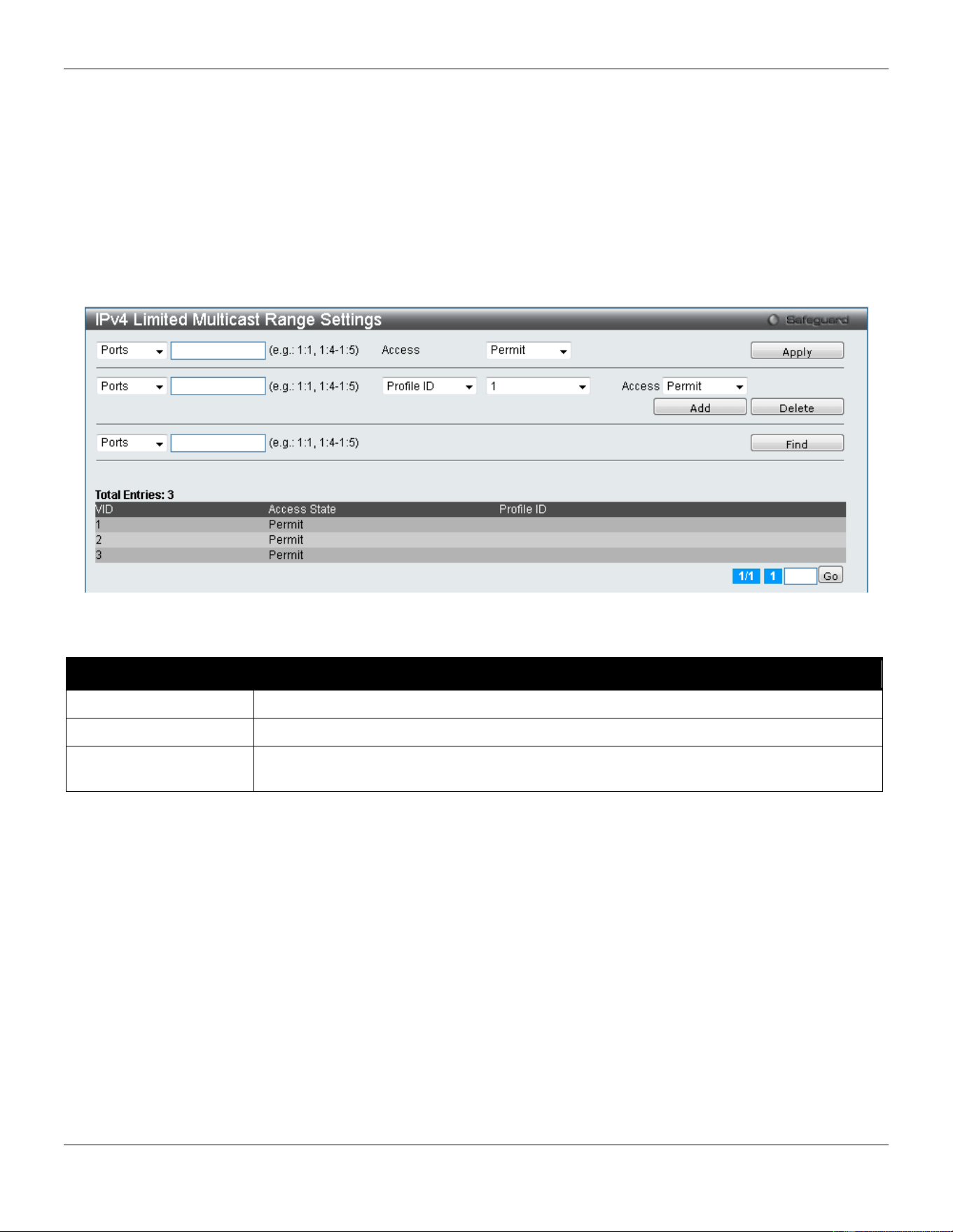
xStack® DGS-3420 Series Layer 2 Managed Stackable Gigabit Switch Web UI Reference Guide
158
Click the Edit button to re-configure the specific entry.
Click the Delete button to remove the specific entry.
IPv4 Limited Multicast Range Settings
Users can configure the ports and VLANs on the Switch that will be involved in the Limited IPv4 Multicast Range. The
user can configure the range of multicast ports that will be accepted by the source ports to be forwarded to the receiver
ports.
To view the following window, click L2 Features > Multicast Filtering > IPv4 Multicast Filtering > IPv4 Limited
Multicast Range Settings, as show below:
Figure 4-97 IPv4 Limited Multicast Range Settings window
The fields that can be configured are described below:
Parameter Description
Ports / VID List
Select the appropriate port(s) or VLAN IDs used for the configuration.
Access
Assign access permissions to the ports selected. Options listed are Permit and Deny.
Profile ID / Profile
Name
Use the drop-down menu to select the profile ID or profile name used and then assign
Permit or Deny access to them.
Click the Apply button to accept the changes made.
Click the Add button to add a new entry based on the information entered.
Click the Delete button to remove the specific entry.
Click the Find button to locate a specific entry based on the information entered.
Enter a page number and click the Go button to navigate to a specific page when multiple pages exist.
IPv4 Max Multicast Group Settings
Users can configure the ports and VLANs on the switch that will be a part of the maximum filter group, up to a
maximum of 1024.
To view the following window, click L2 Features > Multicast Filtering > IPv4 Multicast Filtering > IPv4 Max
Multicast Group Settings, as show below:
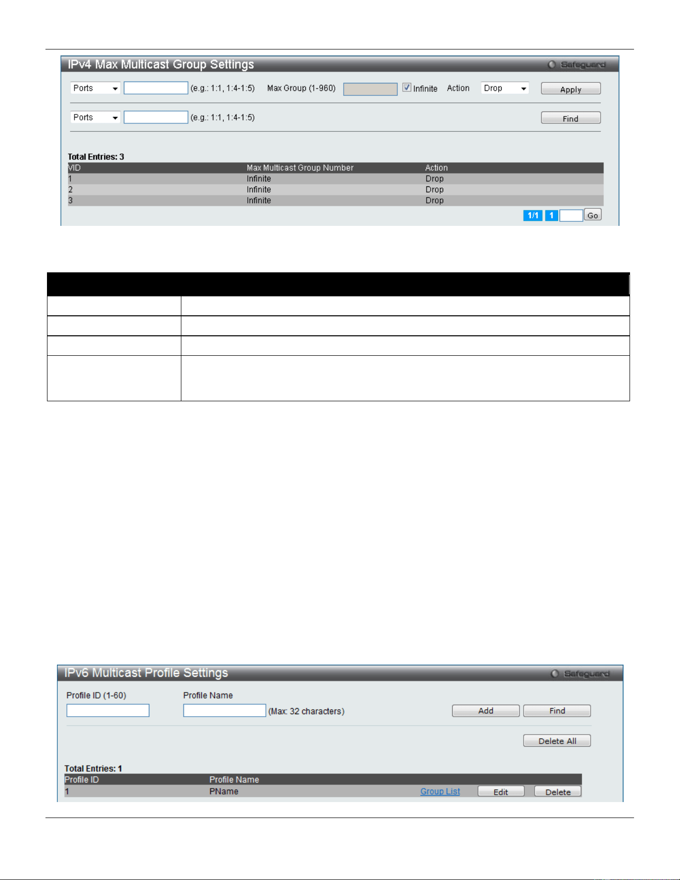
xStack® DGS-3420 Series Layer 2 Managed Stackable Gigabit Switch Web UI Reference Guide
159
Figure 4-98 IPv4 Max Multicast Group Settings window
The fields that can be configured are described below:
Parameter Description
Ports / VID List
Select the appropriate port(s) or VLAN IDs used for the configuration here.
Max Group (1-960)
If the checkbox Infinite is not selected, the user can enter a Max Group value.
Infinite
Tick the check box to enable or disable the use of the Infinite value.
Action
Use the drop-down menu to select the appropriate action for this rule. The user can
select Drop to initiate the drop action or the user can select Replace to initiate the
replace action.
Click the Apply button to accept the changes made.
Click the Find button to locate a specific entry based on the information entered.
Enter a page number and click the Go button to navigate to a specific page when multiple pages exist.
IPv6 Multicast Filtering
Users can add a profile to which multicast address(s) reports are to be received on specified ports on the Switch. This
function will therefore limit the number of reports received and the number of multicast groups configured on the Switch.
The user may set an IPv6 Multicast address or range of IPv6 Multicast addresses to accept reports (Permit) or deny
reports (Deny) coming into the specified switch ports.
IPv6 Multicast Profile Settings
Users can add, delete, and configure the IPv6 multicast profile on this page.
To view the following window, click L2 Features > Multicast Filtering > IPv6 Multicast Filtering > IPv6 Multicast
Profile Settings, as show below:
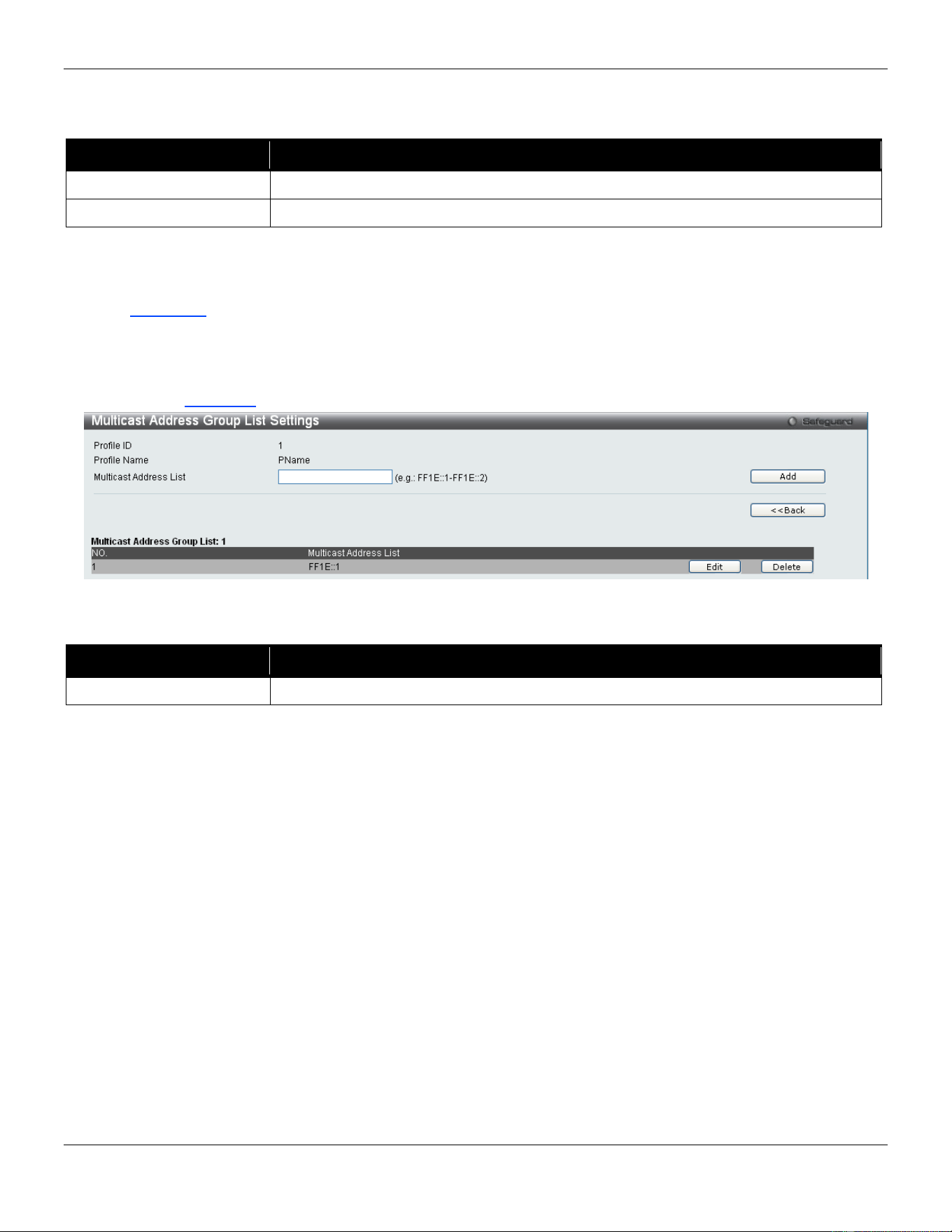
xStack® DGS-3420 Series Layer 2 Managed Stackable Gigabit Switch Web UI Reference Guide
160
Figure 4-99 IPv6 Multicast Profile Settings window
The fields that can be configured are described below:
Parameter Description
Profile ID (1-60)
Enter a Profile ID between 1 and 60.
Profile Name
Enter a name for the IP Multicast Profile.
Click the Add button to add a new entry based on the information entered.
Click the Find button to locate a specific entry based on the information entered.
Click the Delete All button to remove all the entries listed.
Click the Group List link to configure the multicast address group list settings for the specific entry.
Click the Edit button to re-configure the specific entry.
Click the Delete button to remove the specific entry.
After clicking the Group List link, the following page will appear:
Figure 4-100 Multicast Address Group List Settings window
The fields that can be configured are described below:
Parameter Description
Multicast Address List
Enter the multicast address list here.
Click the Add button to add a new entry based on the information entered.
Click the <<Back button to discard the changes made and return to the previous page.
Click the Edit button to re-configure the specific entry.
Click the Delete button to remove the specific entry.
IPv6 Limited Multicast Range Settings
Users can configure the ports and VLANs on the Switch that will be involved in the Limited IPv6 Multicast Range.
To view the following window, click L2 Features > Multicast Filtering > IPv6 Multicast Filtering > IPv6 Limited
Multicast Range Settings, as show below:
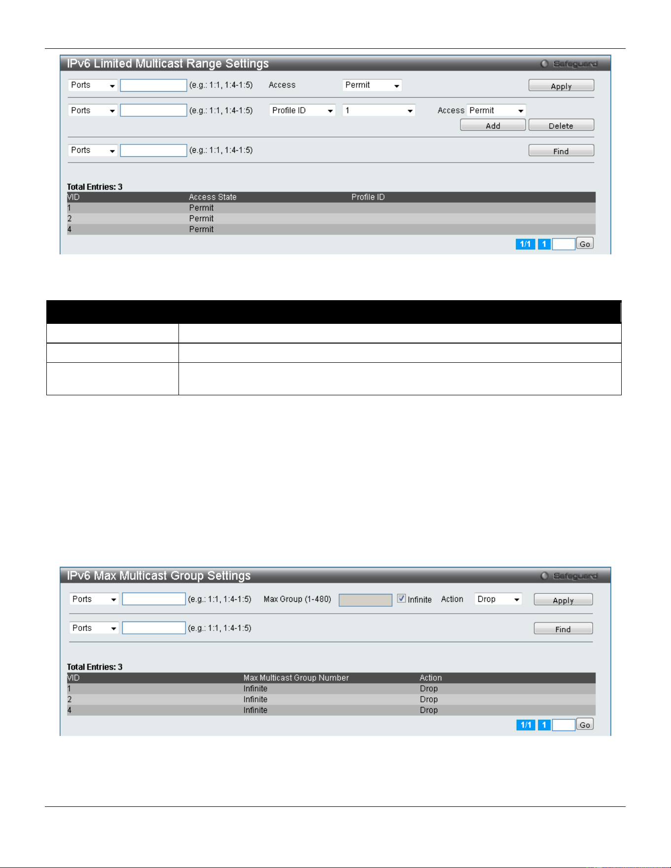
xStack® DGS-3420 Series Layer 2 Managed Stackable Gigabit Switch Web UI Reference Guide
161
Figure 4-101 IPv6 Limited Multicast Range Settings window
The fields that can be configured are described below:
Parameter Description
Ports/VID List
Select the appropriate port(s) or VLAN IDs used for the configuration here.
Access
Assign access permissions to the ports selected. Options listed are Permit and Deny.
Profile ID/Profile Name
Use the drop-down menu to select the profile ID or profile name used and then assign
Permit or Deny access to them.
Click the Apply button to accept the changes made.
Click the Add button to add a new entry based on the information entered.
Click the Delete button to remove the specific entry.
Click the Find button to locate a specific entry based on the information entered.
Enter a page number and click the Go button to navigate to a specific page when multiple pages exist.
IPv6 Max Multicast Group Settings
Users can configure the ports and VLANs on the switch that will be a part of the maximum filter group, up to a
maximum of 1024.
Figure 4-102 IPv6 Max Multicast Group Settings window
The fields that can be configured are described below:
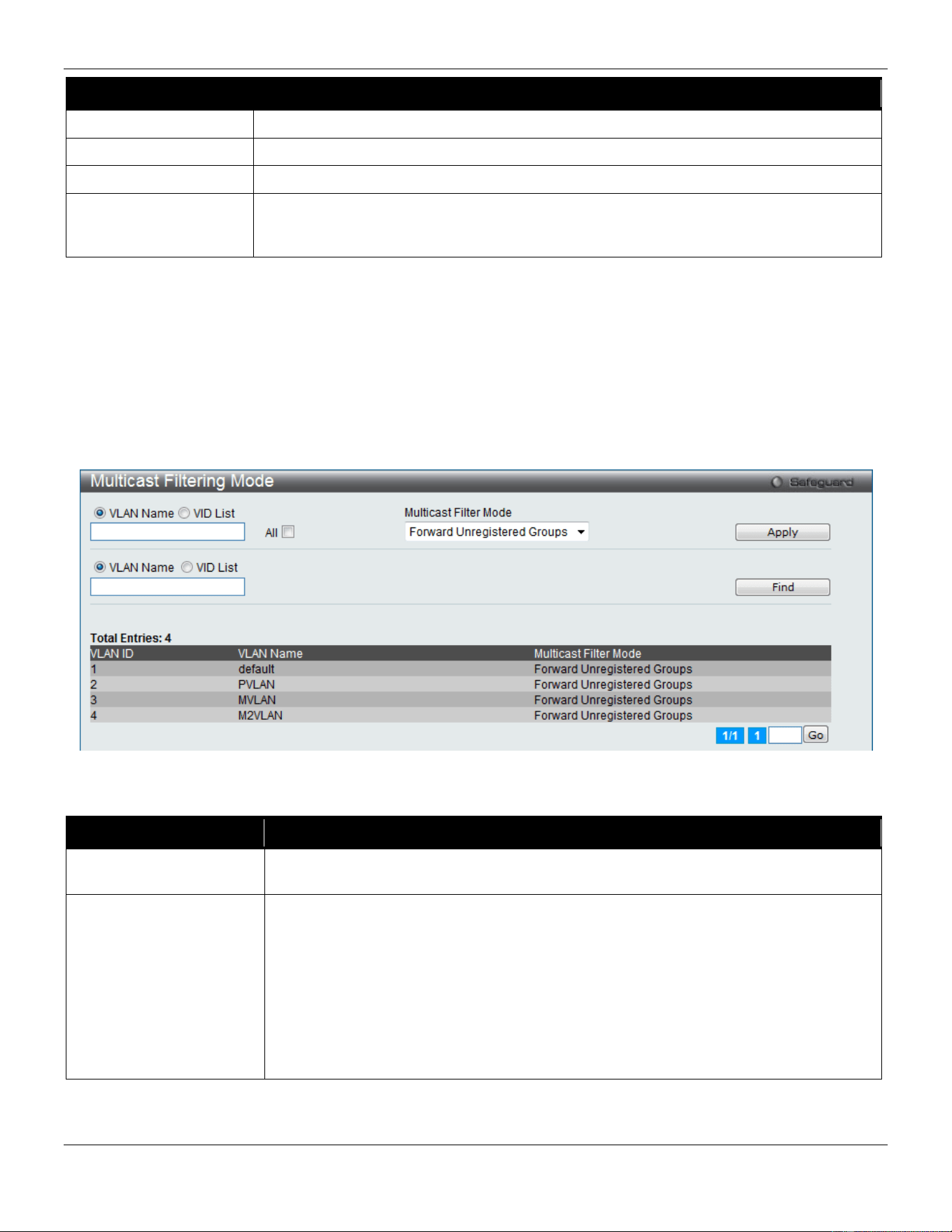
xStack® DGS-3420 Series Layer 2 Managed Stackable Gigabit Switch Web UI Reference Guide
162
Parameter Description
Ports/VID List
Select the appropriate port(s) or VLAN IDs used for the configuration here.
Max Group
If the checkbox Infinite is not selected, the user can enter a Max Group value.
Infinite
Tick the check box to enable or disable the use of the Infinite value.
Action
Use the drop-down menu to select the appropriate action for this rule. The user can
select Drop to initiate the drop action or the user can select Replace to initiate the
replace action.
Click the Apply button to accept the changes made.
Click the Find button to locate a specific entry based on the information entered.
Enter a page number and click the Go button to navigate to a specific page when multiple pages exist.
Multicast Filtering Mode
Users can configure the multicast filtering mode.
To view the following window, click L2 Features > Multicast Filtering > Multicast Filtering Mode, as show below:
Figure 4-103 Multicast Filtering Mode window
The fields that can be configured are described below:
Parameter Description
VLAN Name/VID List The VLAN to which the specified filtering action applies. Tick the All check box to apply
this feature to all the VLANs.
Multicast Filtering Mode
This drop-down menu allows you to select the action the Switch will take when it
receives a multicast packet that requires forwarding to a port in the specified VLAN.
Forward All Groups – This will instruct the Switch to forward all multicast packets to the
specified VLAN.
Forward Unregistered Groups – The multicast packets whose destination is an
unregistered multicast group will be forwarded within the range of ports specified
above.
Filter Unregistered Groups – The multicast packets whose destination is a registered
multicast group will be forwarded within the range of ports specified above.
Click the Apply button to accept the changes made.
Click the Find button to locate a specific entry based on the information entered.
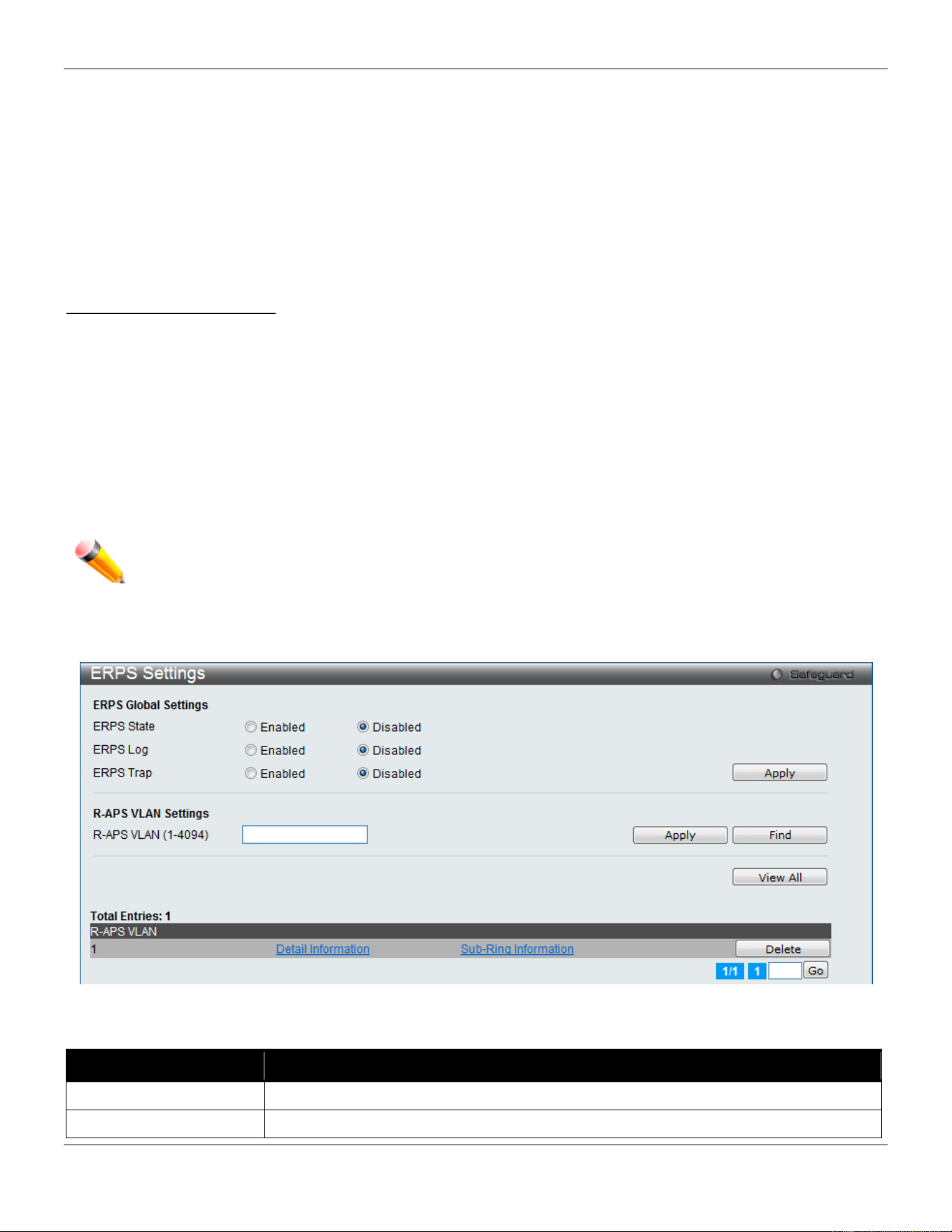
xStack® DGS-3420 Series Layer 2 Managed Stackable Gigabit Switch Web UI Reference Guide
163
Enter a page number and click the Go button to navigate to a specific page when multiple pages exist.
ERPS Settings
Ethernet Ring Protection Switching (ERPS) is the first industry standard (ITU-T G.8032) for ERPS. ERPS provides sub-
50ms protection for Ethernet traffic in a ring topology. It ensures that there are no loops formed at the Ethernet layer.
One link within a ring will be blocked to avoid Loop (RPL, Ring Protection Link). When the failure happens, protection
switching blocks the failed link and unblocks the RPL. When the failure clears, protection switching blocks the RPL
again and unblocks the link on which the failure is cleared.
G.8032 Terms and Concepts
RPL (Ring Protection Link) – Link designated by mechanism that is blocked during Idle state to prevent loop on
Bridged ring
RPL Owner – Node connected to RPL that blocks traffic on RPL during Idle state and unblocks during Protected state
R-APS (Ring – Automatic Protection Switching) – A feature defined in Y.1731 and G.8032 used to coordinate the
protection actions over the ring through RAPS VLAN (R-APS Channel).
RAPS VLAN (R-APS Channel) – A separate ring-wide VLAN for transmission of R-APS messages
Protected VLAN – The service traffic VLANs for transmission of normal network traffic
This page is used to enable the ERPS function on the switch.
NOTE: STP and LBD should be disabled on the ring ports before enabling ERPS. The ERPS cannot be
enabled before the R-APS VLAN is created, and ring ports, RPL port, RPL owner, are configured.
To view the following window, click L2 Features > ERPS Settings, as show below:
Figure 4-104 ERPS Settings Window
The fields that can be configured are described below:
Parameter Description
ERPS State
Here the user can enable or disable the ERPS State.
ERPS Log
Here the user can enable or disable the ERPS Log.
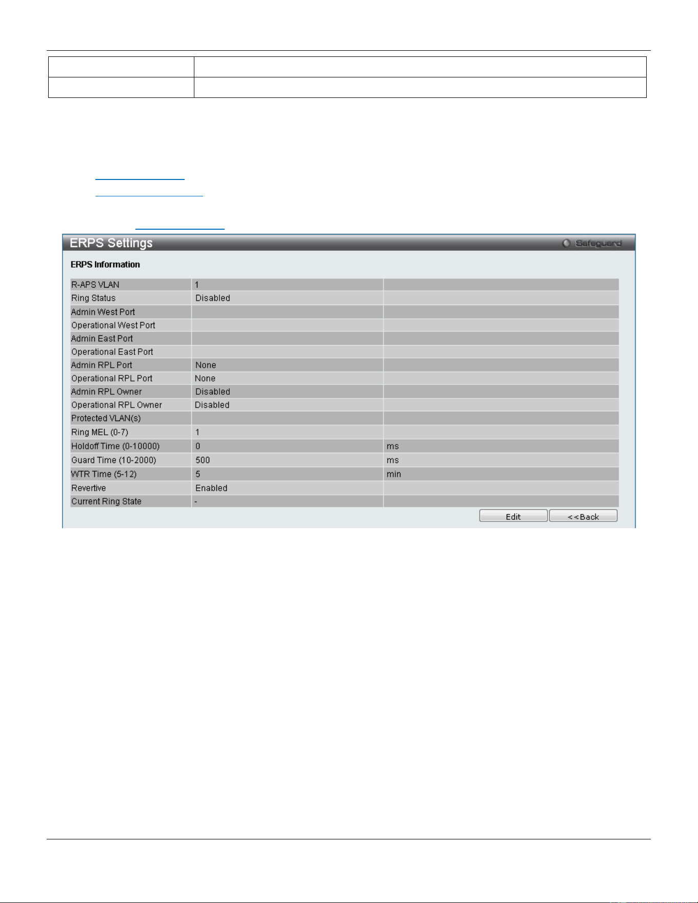
xStack® DGS-3420 Series Layer 2 Managed Stackable Gigabit Switch Web UI Reference Guide
164
ERPS Trap
Here the user can enable or disable the ERPS Trap.
R-APS VLAN (1-4094)
Specifies the VLAN which will be the R-APS VLAN.
Click the Apply button to accept the changes made.
Click the Find button to find a specific entry based on the information entered.
Click the View All button to view all the entries configured.
Click the Delete button to remove the specific entry.
Click the Detail Information link to view detailed information of the R-APS entry.
Click the Sub-Ring Information link to view the Sub-Ring information of the R-APS entry.
After clicking the Detail Information link, the following window will appear:
Click the Edit button to re-configure the specific entry.
Click the <<Back button to return to the ERPS settings page.
After click the Edit button, the following window will appear:
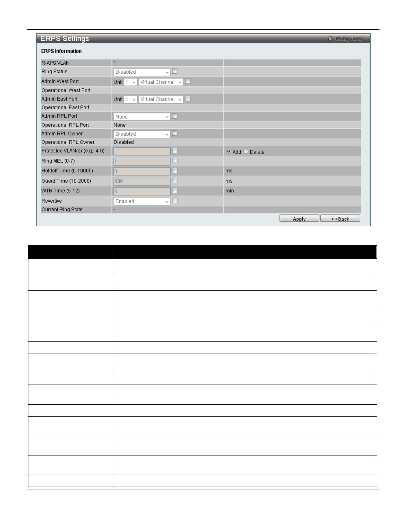
xStack® DGS-3420 Series Layer 2 Managed Stackable Gigabit Switch Web UI Reference Guide
165
The fields that can be configured or displayed are described below:
Parameter Description
R-APS VLAN
Display the R-APS VLAN ID.
Ring Status
Tick the check box and use the drop-down menu to enable or disable the specified
ring.
Admin West Port
Tick the check box and use the drop-down menu to specify the port as the west ring
port and also the virtual port channel used. Select the Unit you wish to configure.
Operational West Port
The operational west port value is displayed.
Admin East Port
Tick the check box and use the drop-down menu to specify the port as the east ring
port and also the virtual port channel used. Select the Unit you wish to configure.
Operational East Port
Display the operational east port value.
Admin RPL Port
Tick the check box and use the drop-down menu to specify the RPL port used. Options
to choose from are West Port, East Port, and None.
Operational RPL Port
Display the operational RPL port value.
Admin RPL Owner
Tick the check box and use the drop-down menu to enable or disable the RPL owner
node.
Operational RPL Owner
Display the operational RPL owner value.
Protected VLAN(s) Tick the check box, click the Add or Delete radio button, and enter the protected VLAN
group.
Ring MEL (0-7)
Tick the check box and enter the ring MEL of the R-APS function. The default ring MEL
is 1.
Holdoff Time (0-10000)
Tick the check box and enter the hold-off time of the R-APS function. The default hold-
off time is 0 milliseconds.
Guard Time (10-2000)
Tick the check box and enter the guard time of the R-APS function. The default guard
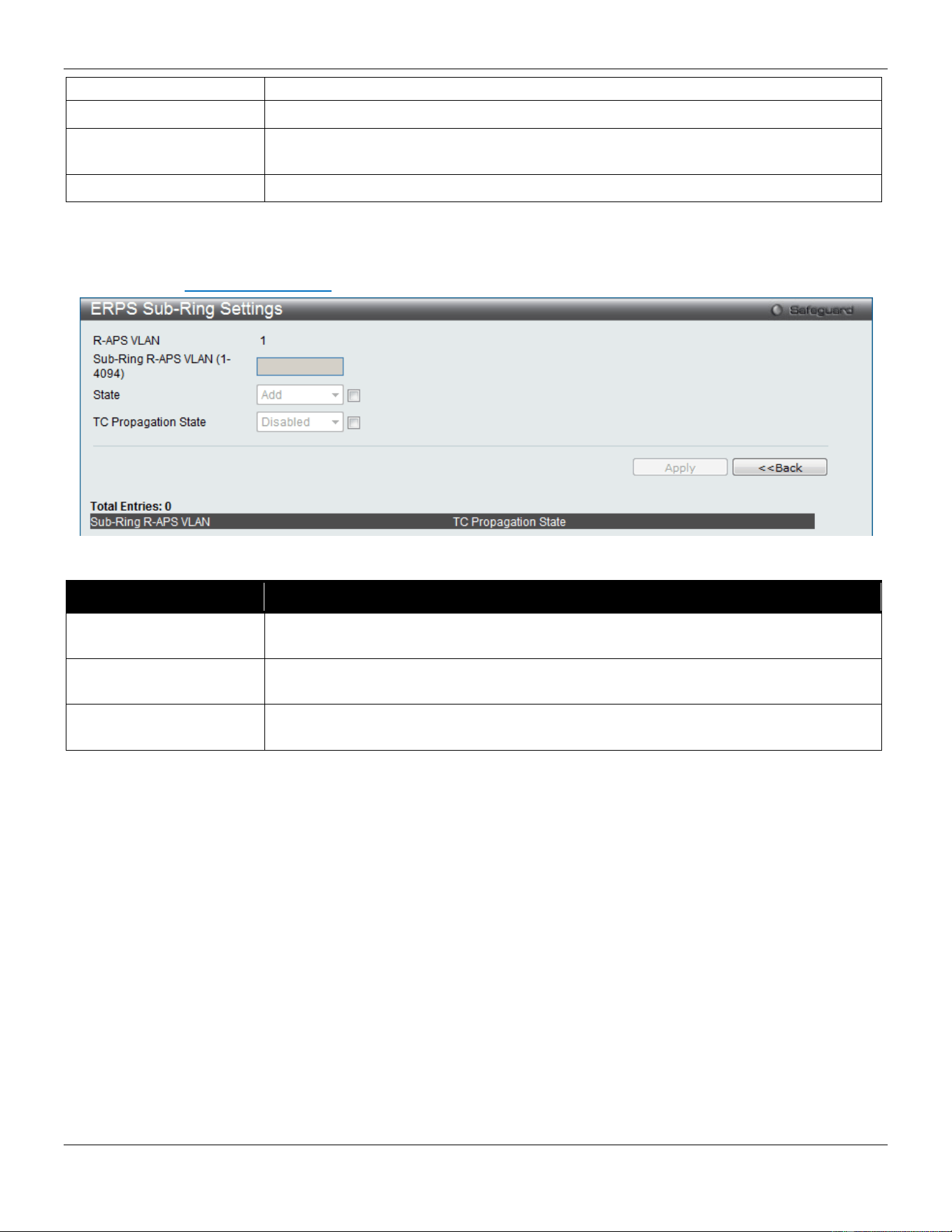
xStack® DGS-3420 Series Layer 2 Managed Stackable Gigabit Switch Web UI Reference Guide
166
time is 500 milliseconds.
WTR Time (5-12)
Tick the check box and enter the WTR time of the R-APS function.
Revertive
Tick the check box and use the drop-down menu to enable or disable the state of the
R-APS revertive option.
Current Ring State
Display the current Ring state.
Click the Apply button to accept the changes made.
Click the <<Back button to return to the previous window.
After clicking the Sub-Ring Information link, the following window will appear:
The fields that can be configured are described below:
Parameter Description
Sub-Ring R-APS VLAN
(1-4094)
Enter the Sub-Ring R-APS VLAN ID used here.
State
Tick the check box and use the drop-down menu to add or delete the ERPS Sub-Ring
state.
TC Propagation State
Tick the check box and use the drop-down menu to enable or disable the TC
Propagation state.
Click the Apply button to accept the changes made.
Click the <<Back button to return to the previous window.
LLDP
The Link Layer Discovery Protocol (LLDP) allows stations attached to an IEEE 802 LAN to advertise, to other stations
attached to the same IEEE 802 LAN. The major capabilities provided by this system is that it incorporates the station,
the management address or addresses of the entity or entities that provide management of those capabilities, and the
identification of the station’s point of attachment to the IEEE 802 LAN required by those management entity or entities.
The information distributed via this protocol is stored by its recipients in a standard Management Information Base
(MIB), making it possible for the information to be accessed by a Network Management System (NMS) through a
management protocol such as the Simple Network Management Protocol (SNMP).
LLDP
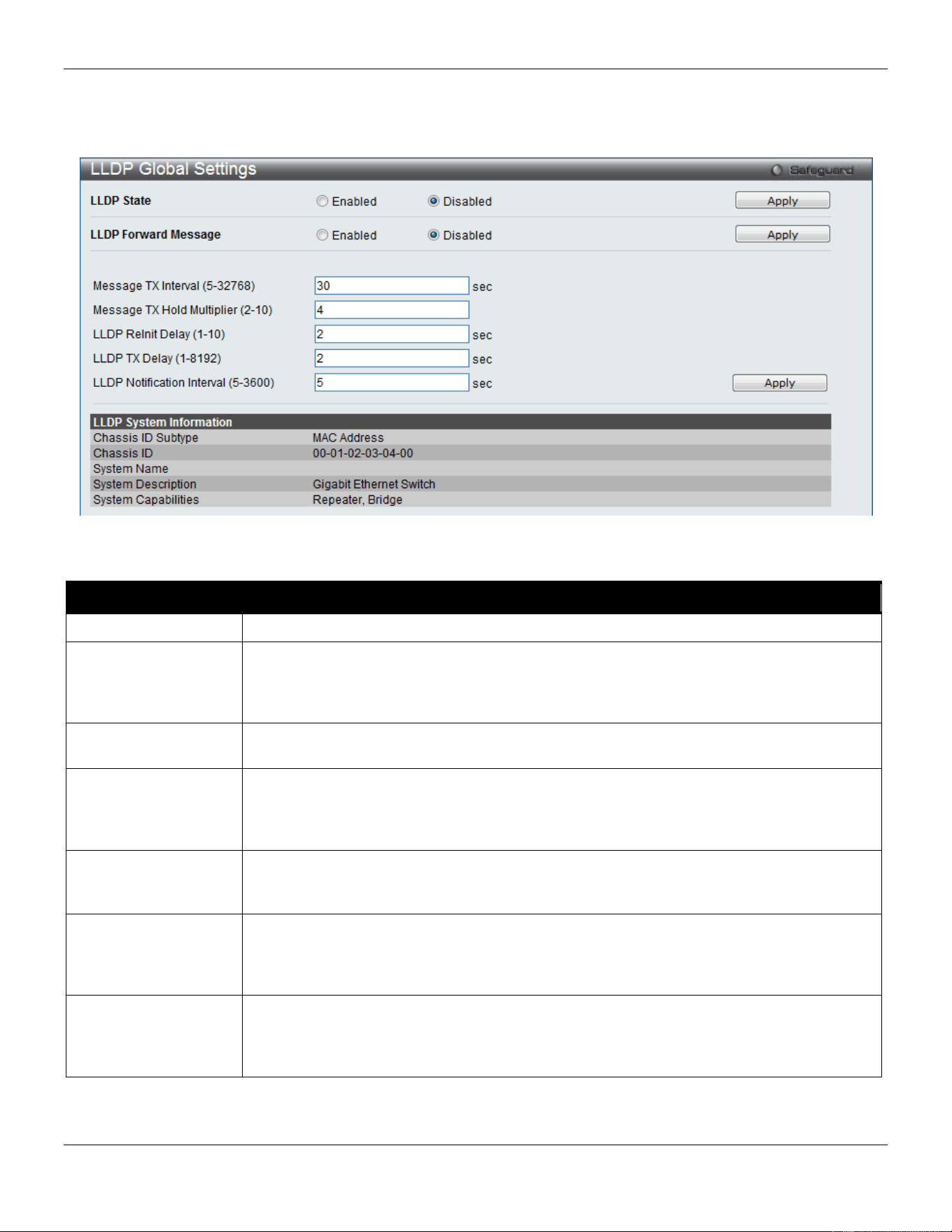
xStack® DGS-3420 Series Layer 2 Managed Stackable Gigabit Switch Web UI Reference Guide
167
LLDP Global Settings
On this page the user can configure the LLDP global parameters.
To view the following window, click L2 Features > LLDP > LLDP> LLDP Global Settings, as show below:
Figure 4-105 LLDP Global Settings window
The fields that can be configured are described below:
Parameter Description
LLDP State
Click the radio buttons to enable or disable the LLDP feature.
LLDP Forward
Message
When LLDP is disabled this function controls the LLDP packet forwarding message based
on individual ports. If LLDP is enabled on a port it will flood the LLDP packet to all ports
that have the same port VLAN and will advertise to other stations attached to the same
IEEE 802 LAN.
Message TX Interval
(5-32768)
This interval controls how often active ports retransmit advertisements to their neighbors.
To change the packet transmission interval, enter a value between 5 and 35768 seconds.
Message TX Hold
Multiplier (2-10)
This function calculates the Time-to-Live for creating and transmitting the LLDP
advertisements to LLDP neighbors by changing the multiplier used by an LLDP Switch.
When the Time-to-Live for an advertisement expires the advertised data is then deleted
from the neighbor Switch’s MIB.
LLDP ReInit Delay (1-
10)
The LLDP re-initialization delay interval is the minimum time that an LLDP port will wait
before reinitializing after receiving an LLDP disable command. To change the LLDP re-init
delay, enter a value between 1 and 10 seconds.
LLDP TX Delay
(1-8192)
LLDP TX Delay allows the user to change the minimum time delay interval for any LLDP
port which will delay advertising any successive LLDP advertisements due to change in
the LLDP MIB content. To change the LLDP TX Delay, enter a value between 1 and 8192
seconds.
LLDP Notification
Interval (5-3600)
LLDP Notification Interval is used to send notifications to configured SNMP trap
receiver(s) when an LLDP change is detected in an advertisement received on the port
from an LLDP neighbor. To set the LLDP Notification Interval, enter a value between 5
and 3600 seconds.
Click the Apply button to accept the changes made for each individual section.
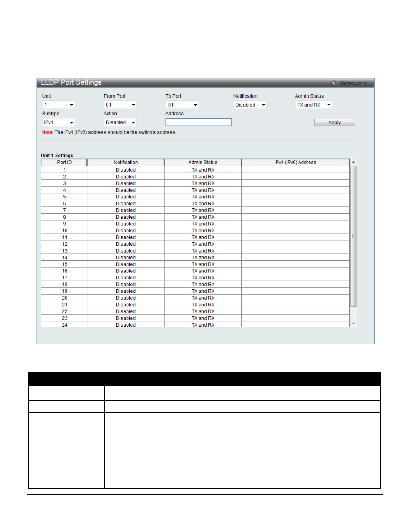
xStack® DGS-3420 Series Layer 2 Managed Stackable Gigabit Switch Web UI Reference Guide
168
LLDP Port Settings
On this page the user can configure the LLDP port parameters.
To view the following window, click L2 Features > LLDP > LLDP> LLDP Port Settings, as show below:
Figure 4-106 LLDP Port Settings window
The fields that can be configured are described below:
Parameter Description
Unit
Select the unit you wish to configure.
From Port / To Port
Use the drop-down menu to select the starting and ending ports to use.
Notification
Use the drop-down menu to enable or disable the status of the LLDP notification. This
function controls the SNMP trap however it cannot implement traps on SNMP when the
notification is disabled.
Admin Status
This function controls the local LLDP agent and allows it to send and receive LLDP frames
on the ports. This option contains TX, RX, TX And RX or Disabled.
TX - the local LLDP agent can only transmit LLDP frames.
RX - the local LLDP agent can only receive LLDP frames.
TX And RX - the local LLDP agent can both transmit and receive LLDP frames.
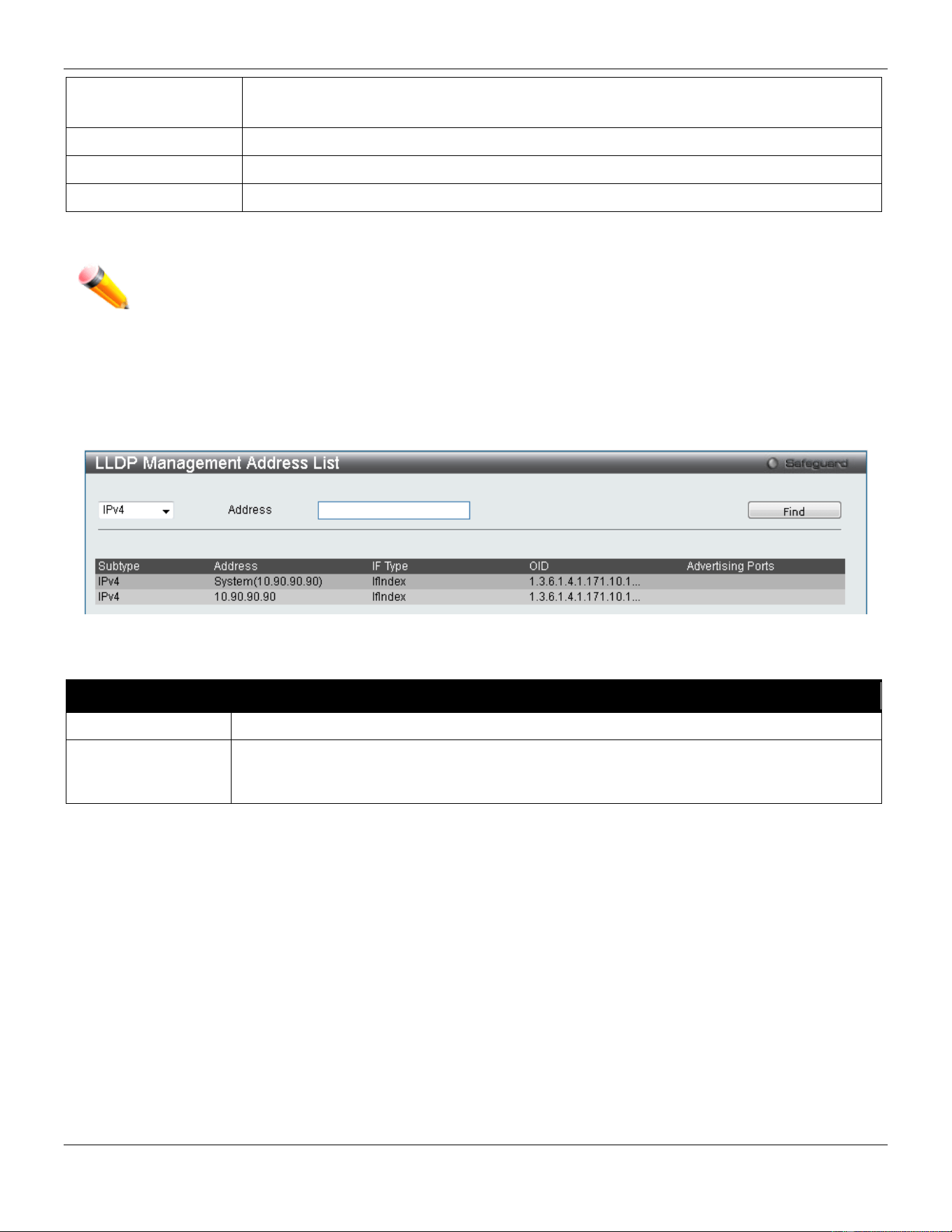
xStack® DGS-3420 Series Layer 2 Managed Stackable Gigabit Switch Web UI Reference Guide
169
Disabled - the local LLDP agent can neither transmit nor receive LLDP frames.
The default value is TX And RX.
Subtype
Use the drop-down menu to select the type of the IP address information will be sent.
Action
Use the drop-down menu to enable or disable the action field.
Address
Enter the IP address that will be sent.
Click the Apply button to accept the changes made.
NOTE: The IPv4 or IPv6 address entered here should be an existing LLDP management IP address.
LLDP Management Address List
On this page the user can view the LLDP management address list.
To view the following window, click L2 Features > LLDP > LLDP> LLDP management Address List, as show below:
Figure 4-107 LLDP Management Address List window
The fields that can be configured are described below:
Parameter Description
IPv4/IPv6
Use the drop-down menu to select either IPv4 or IPv6.
Address
Enter the management IP address or the IP address of the entity you wish to advertise to.
The IPv4 address is a management IP address, so the IP information will be sent with the
frame.
Click the Find button to locate a specific entry based on the information entered.
LLDP Basic TLVs Settings
TLV stands for Type-length-value, which allows the specific sending information as a TLV element within LLDP
packets. This window is used to enable the settings for the Basic TLVs Settings. An active LLDP port on the Switch
always included mandatory data in its outbound advertisements. There are four optional data types that can be
configured for an individual port or group of ports to exclude one or more of these data types from outbound LLDP
advertisements. The mandatory data type includes four basic types of information (end of LLDPDU TLV, chassis ID
TLV, port ID TLV, and Time to Live TLV). The mandatory data types cannot be disabled. There are also four data types
which can be optionally selected. These include Port Description, System Name, System Description and System
Capability.
To view the following window, click L2 Features > LLDP > LLDP> LLDP Basic TLVs Settings, as show below:
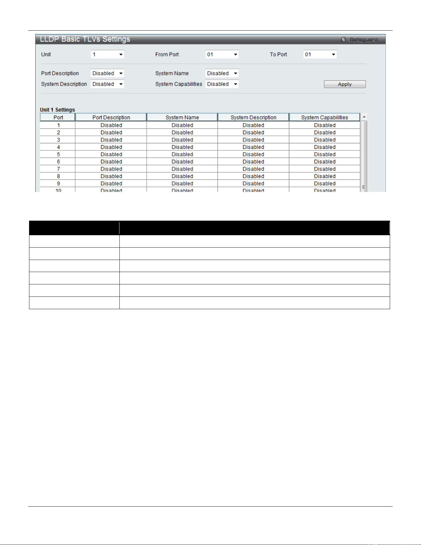
xStack® DGS-3420 Series Layer 2 Managed Stackable Gigabit Switch Web UI Reference Guide
170
Figure 4-108 LLDP Basic TLVs Settings window
The fields that can be configured are described below:
Parameter Description
Unit
Select the unit you wish to configure.
From Port / To Port
Select the port range to use for this configuration.
Port Description
Use the drop-down menu to enable or disable the Port Description option.
System Name
Use the drop-down menu to enable or disable the System Name option.
System Description
Use the drop-down menu to enable or disable the System Description option.
System Capabilities
Use the drop-down menu to enable or disable the System Capabilities option.
Click the Apply button to accept the changes made.
LLDP Dot1 TLVs Settings
LLDP Dot1 TLVs are organizationally specific TLVs which are defined in IEEE 802.1 and used to configure an
individual port or group of ports to exclude one or more of the IEEE 802.1 organizational port VLAN ID TLV data types
from outbound LLDP advertisements.
To view the following window, click L2 Features > LLDP > LLDP> LLDP Dot1 TLVs Settings, as show below:
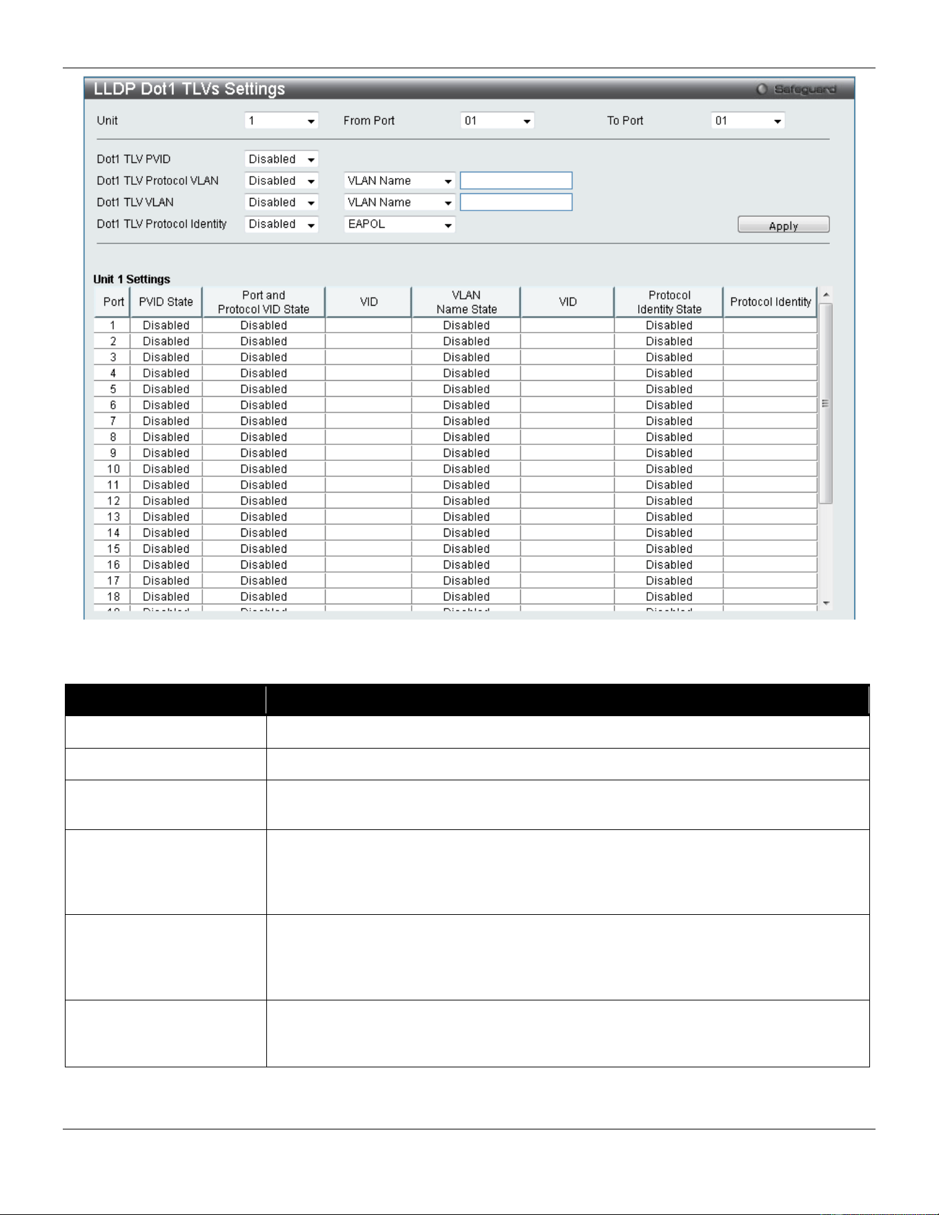
xStack® DGS-3420 Series Layer 2 Managed Stackable Gigabit Switch Web UI Reference Guide
171
Figure 4-109 LLDP Dot1 TLVs Settings window
The fields that can be configured are described below:
Parameter Description
Unit
Select the unit you wish to configure.
From Port / To Port
Select the port range to use for this configuration.
Dot1 TLV PVID
Use the drop-down menu to enable or disable and configure the Dot1 TLV PVID
option.
Dot1 TLV Protocol VLAN
Use the drop-down menu to enable or disable, and configure the Dot1 TLV Protocol
VLAN option. After enabling this option, the user can select to use either VLAN Name,
VLAN ID or All in the next drop-down menu. After selecting this, the user can enter
either the VLAN name or VLAN ID in the space provided.
Dot1 TLV VLAN
Use the drop-down menu to enable or disable, and configure the Dot1 TLV VLAN
option. After enabling this option, the user can select to use either VLAN Name, VLAN
ID or All in the next drop-down menu. After selecting this, the user can enter either the
VLAN name or VLAN ID in the space provided.
Dot1 TLV Protocol
Identity
Use the drop-down menu to enable or disable, and configure the Dot1 TLV Protocol
Identity option. After enabling this option the user can select to either use EAPOL,
LACP, GVRP, STP, or All.
Click the Apply button to accept the changes made.
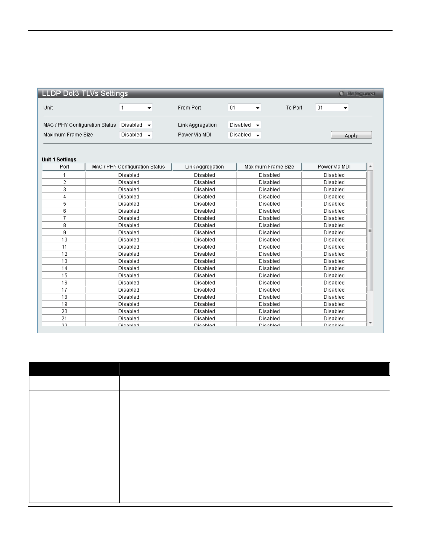
xStack® DGS-3420 Series Layer 2 Managed Stackable Gigabit Switch Web UI Reference Guide
172
LLDP Dot3 TLVs Settings
This window is used to configure an individual port or group of ports to exclude one or more IEEE 802.3 organizational
specific TLV data type from outbound LLDP advertisements.
To view the following window, click L2 Features > LLDP > LLDP> LLDP Dot3 TLVs Settings, as show below:
Figure 4-110 LLDP Dot3 TLVs Settings window
The fields that can be configured are described below:
Parameter Description
Unit
Select the unit you wish to configure.
From Port / To Port
Select the port range to use for this configuration.
MAC / PHY
Configuration Status
This TLV optional data type indicates that the LLDP agent should transmit the
MAC/PHY configuration/status TLV. This indicates it is possible for two ends of an
IEEE 802.3 link to be configured with different duplex and/or speed settings and still
establish some limited network connectivity. More precisely, the information includes
whether the port supports the auto-negotiation function, whether the function is
enabled, whether it has auto-negotiated advertised capability, and what is the
operational MAU type. The default state is Disabled.
Link Aggregation
The Link Aggregation option indicates that LLDP agents should transmit 'Link
Aggregation TLV'. This indicates the current link aggregation status of IEEE 802.3
MACs. More precisely, the information should include whether the port is capable of
doing link aggregation, whether the port is aggregated in an aggregated link, and what
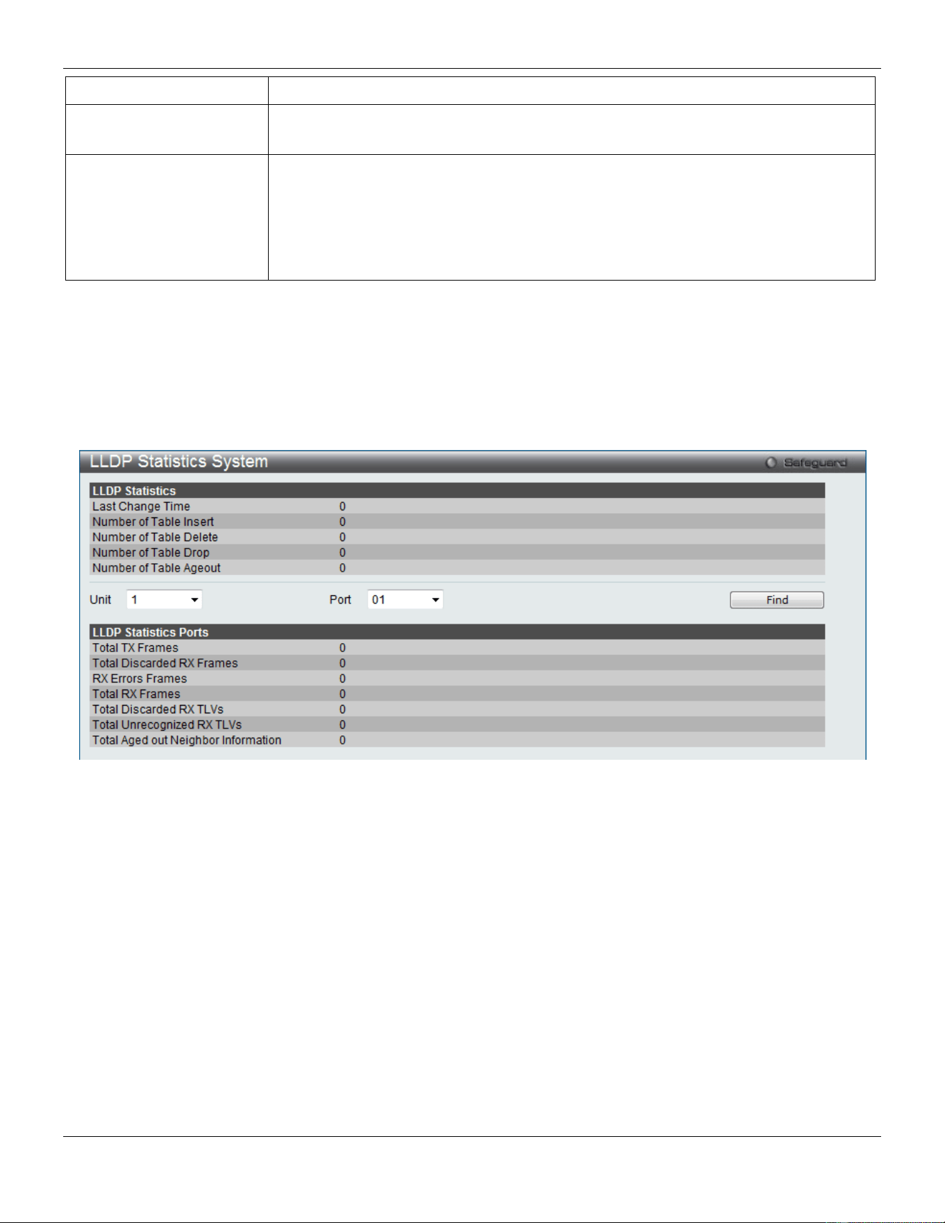
xStack® DGS-3420 Series Layer 2 Managed Stackable Gigabit Switch Web UI Reference Guide
173
is the aggregated port ID. The default state is Disabled.
Maximum Frame Size
The Maximum Frame Size indicates that LLDP agent should transmit 'Maximum-
frame-size TLV. The default state is Disabled.
Power Via MDI
Use the drop down menu to specify whether LLDP agent should transmit Power via
MDI TLV. Three IEEE 802.3 PMD implementations (10BASE-T, 100BASE-TX, and
1000BASE-T) allow power to be supplied over the link for connected non-powered
systems. The Power Via MDI TLV allows network management to advertise and
discover the MDI power support capabilities of the sending IEEE 802.3 LAN station.
The default state is Disabled.
Click the Apply button to accept the changes made.
LLDP Statistic System
The LLDP Statistics System page allows you an overview of the neighbor detection activity, LLDP Statistics and the
settings for individual ports on the Switch. To view the following window, click L2 Features > LLDP > LLDP> LLDP
Statistic System, as show below:
Figure 4-111 LLDP Statistics System window
Select a Unit and Port number from the drop-down menu and click the Find button to view statistics for a certain port.
LLDP Local Port Information
The LLDP Local Port Information page displays the information on a per port basis currently available for populating
outbound LLDP advertisements in the local port brief table shown below.
To view the following window, click L2 Features > LLDP > LLDP> LLDP Local Port Information, as show below:
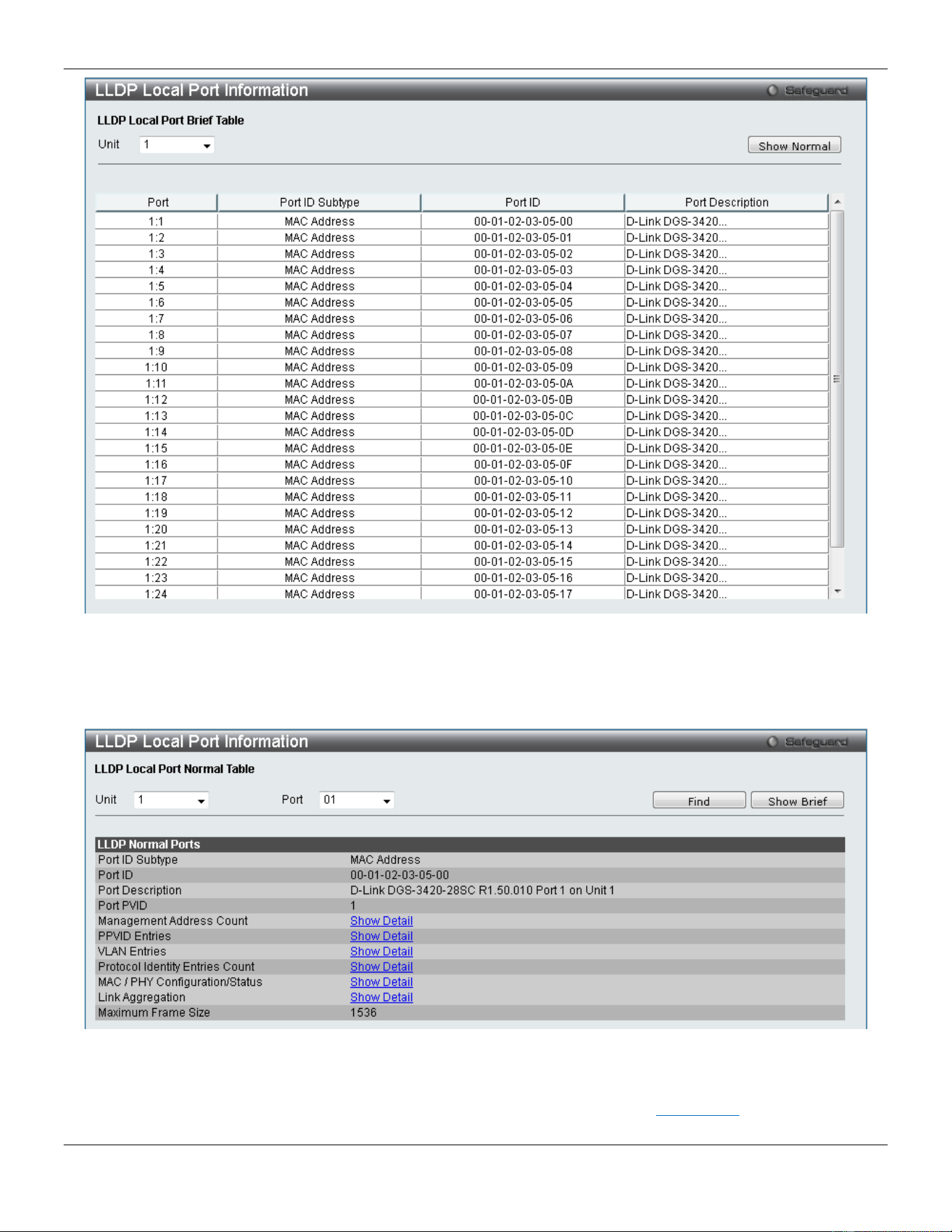
xStack® DGS-3420 Series Layer 2 Managed Stackable Gigabit Switch Web UI Reference Guide
174
Figure 4-112 LLDP Local Port Information window
To view the normal LLDP Local Port information page per port, click the Show Normal button.
To view the brief LLDP Local Port information page per port, click the Show Brief button.
Figure 4-113 LLDP Local Port Information – Show Normal window
Select a Unit and Port number and click the Find button to locate a specific entry.
To view more details about, for example, the Management Address Count, click the Show Detail hyperlink.
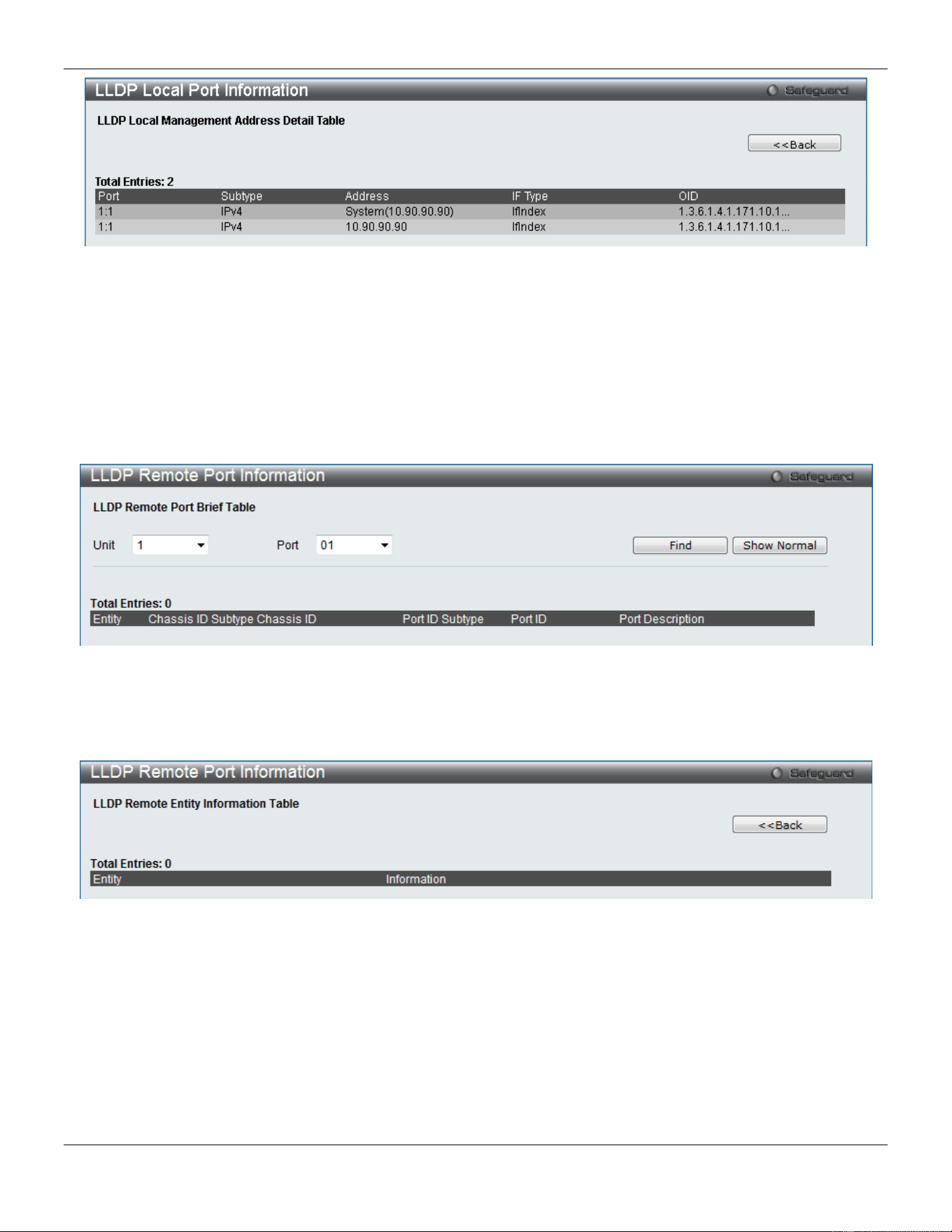
xStack® DGS-3420 Series Layer 2 Managed Stackable Gigabit Switch Web UI Reference Guide
175
Figure 4-114 LLDP Local Port Information – Show Detail window
Click the <<Back button to return to the previous page.
LLDP Remote Port Information
This page displays port information learned from the neighbors. The switch receives packets from a remote station but
is able to store the information as local.
To view the following window, click L2 Features > LLDP > LLDP> LLDP Remote Port Information, as show below:
Figure 4-115 LLDP Remote Port Information window
Select a Unit and Port number from the drop-down menu and click the Find button to view statistics for a certain port.
To view the normal LLDP Remote Port information page per port, click the Show Normal button.
Figure 4-116 LLDP Remote Port Information – Show Normal window
Click the <<Back button to return to the previous page.
LLDP-MED
LLDP-MED System Settings
This window is used to configure the LLDP-MED log state and the fast start repeat count, and display the LLDP-MED
system information.
To view the following window, click L2 Features > LLDP> LLDP-MED > LLDP-MED System Settings, as show below:
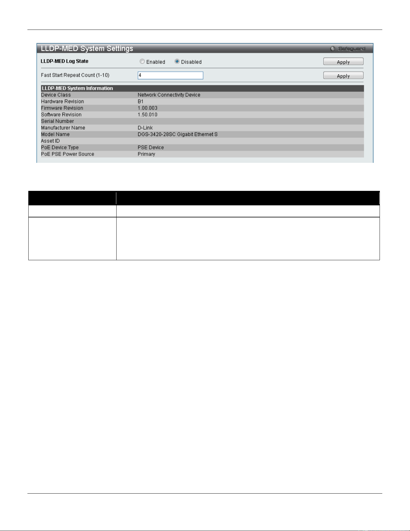
xStack® DGS-3420 Series Layer 2 Managed Stackable Gigabit Switch Web UI Reference Guide
176
Figure 4-117 LLDP-MED System Settings window
The fields that can be configured are described below:
Parameter Description
LLDP-MED Log State
Click the radio buttons to enable or disable the log state of LLDP-MED events.
Fast Start Repeat Count
(1-10)
Enter a value between 1 and 10 for the fast start repeat count. When an LLDP-MED
Capabilities TLV is detected for an MSAP identifier not associated with an existing
LLDP remote system MIB, then the application layer shall start the fast start
mechanism and set the ‘medFastStart’ timer to ‘medFastStartRepeatCount’ times 1.
The default value is 4.
Click the Apply button to accept the changes made for each individual section.
LLDP-MED Port Settings
This window is used to enable or disable transmitting LLDP-MED TLVs.
To view the following window, click L2 Features > LLDP> LLDP-MED > LLDP-MED Port Settings, as show below:
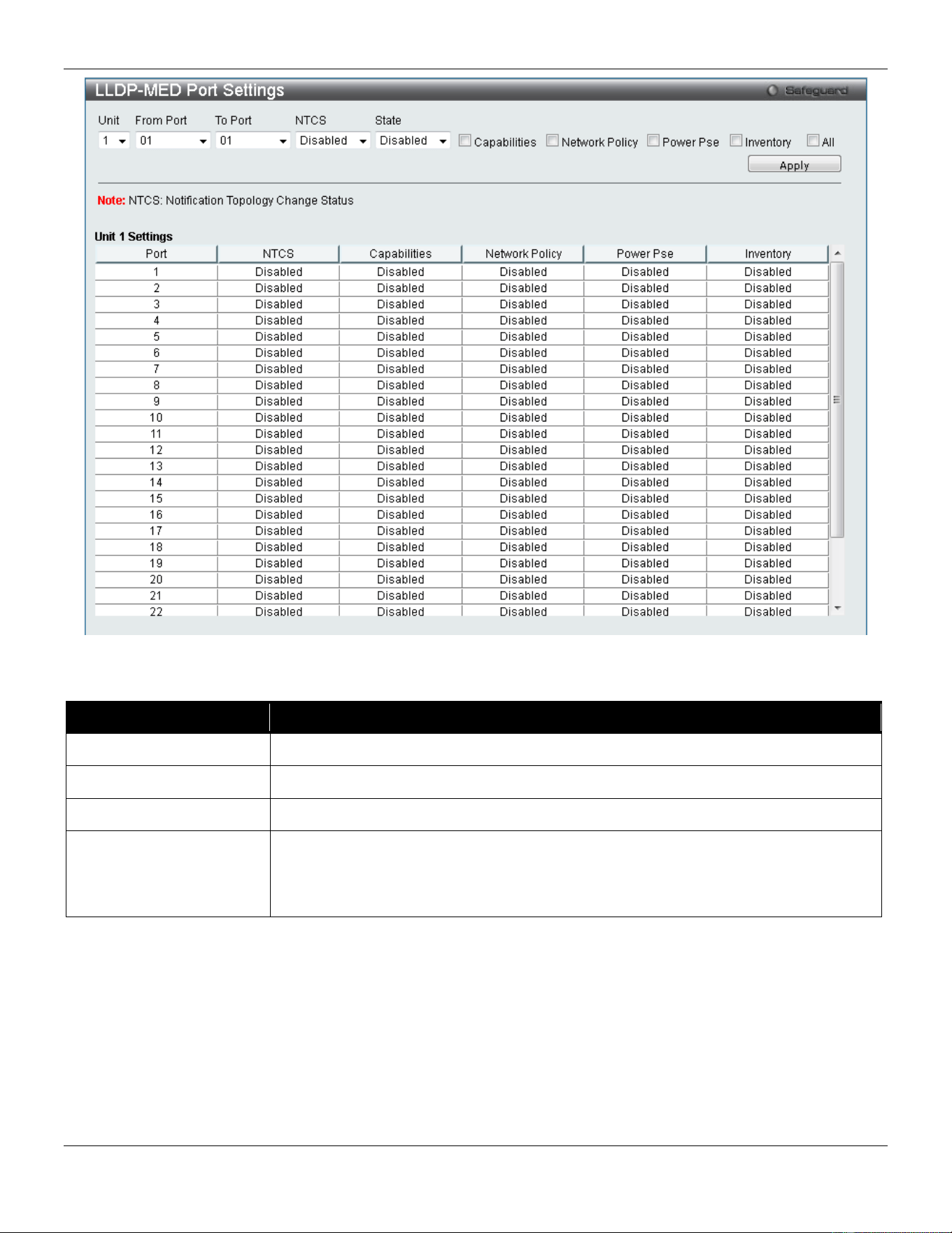
xStack® DGS-3420 Series Layer 2 Managed Stackable Gigabit Switch Web UI Reference Guide
177
Figure 4-118 LLDP-MED Port Settings window
The fields that can be configured are described below:
Parameter Description
Unit
Select the unit you wish to configure.
From Port / To Port
Select the port range to use for this configuration.
NTCS
Use the drop-down menu to enable or disable Notification Topology Change Status.
State
Use the drop-down menu to enable or disable transmit LLDP-MED TLVs, and tick the
check boxes of the TLV types that the LLDP agent should transmit. TLV types are
Capabilities, Network Policy, Power Pse, and Inventory. Tick the All check box to
select all TLV types.
Click the Apply button to accept the changes made.
LLDP-MED Local Port Information
This window displays the per-port information currently available for populating outbound LLDP-MED advertisements.
To view the following window, click L2 Features > LLDP> LLDP-MED > LLDP-MED Local Port Information, as show
below:
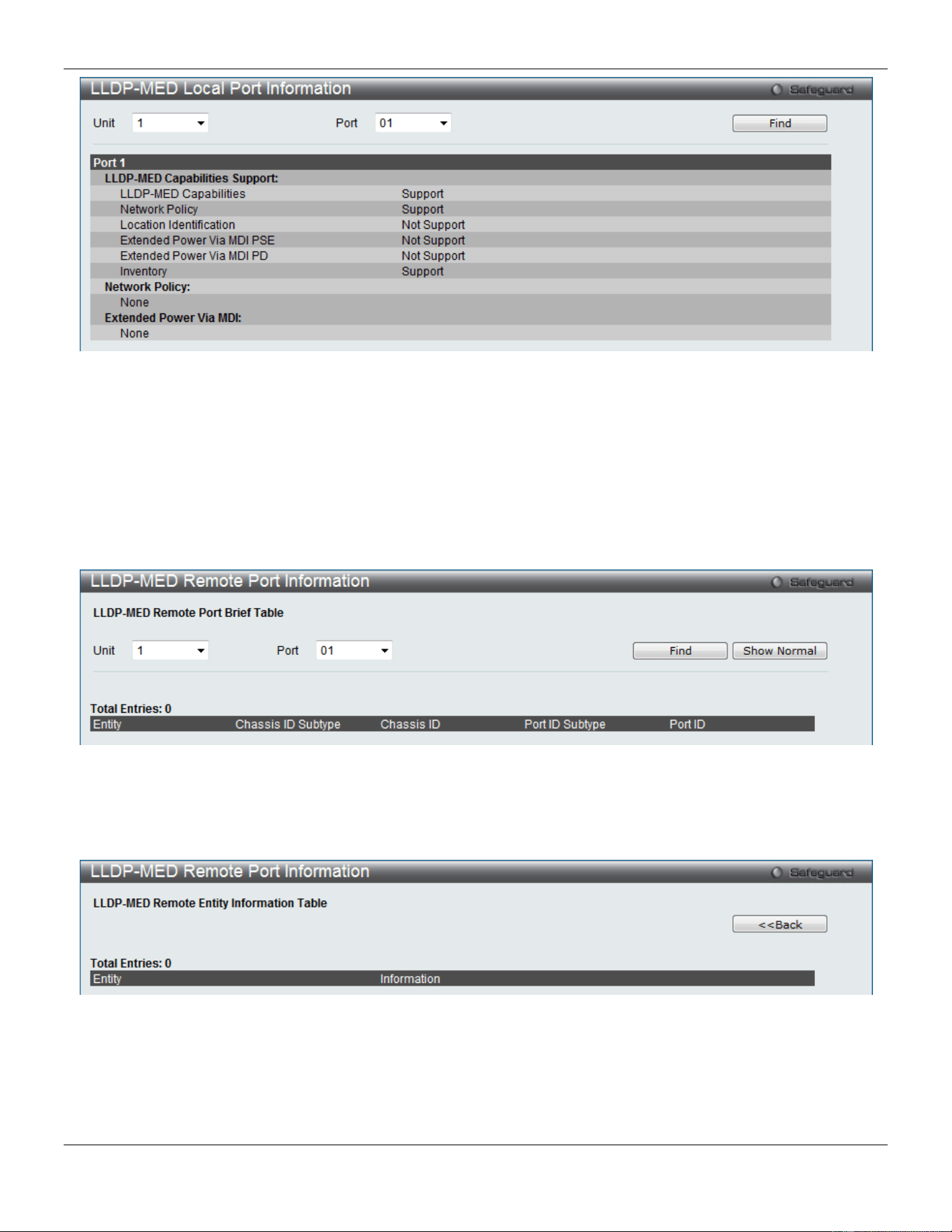
xStack® DGS-3420 Series Layer 2 Managed Stackable Gigabit Switch Web UI Reference Guide
178
Figure 4-119 LLDP-MED Local Port Information window
Select a Unit and Port number from the drop-down menu and click the Find button to view statistics for a certain port.
LLDP-MED Remote Port Information
This window displays the information learned from the neighbor parameters.
To view the following window, click L2 Features > LLDP> LLDP-MED > LLDP-MED Remote Port Information, as
show below:
Figure 4-120 LLDP-MED Remote Port Information window
Select a Unit and Port number from the drop-down menu and click the Find button to view statistics for a certain port.
To view the normal LLDP Remote Port information page per port, click the Show Normal button.
Figure 4-121 LLDP-MED Remote Port Information – Show Normal window
Click the <<Back button to return to the previous page.
NLB FDB Settings
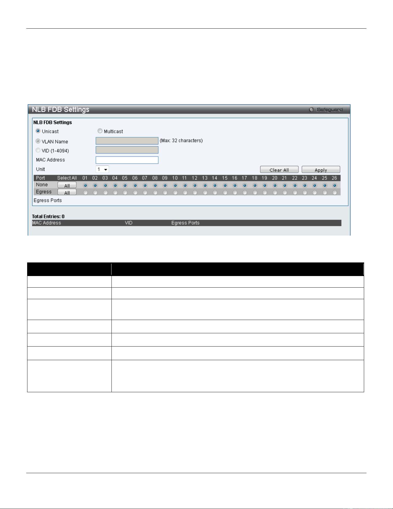
xStack® DGS-3420 Series Layer 2 Managed Stackable Gigabit Switch Web UI Reference Guide
179
The Switch supports Network Load Balancing (NLB). This is a MAC forwarding control for supporting the Microsoft
server load balancing application where multiple servers can share the same IP address and MAC address. The
requests from clients will be forwarded to all servers, but will only be processed by one of them. In multicast mode, the
client uses a multicast MAC address as the destination MAC to reach the server. Regardless of the mode, the
destination MAC is the shared MAC. The server uses its own MAC address (rather than the shared MAC) as the
source MAC address of the reply packet. The NLB multicast FDB entry will be mutually exclusive with the L2 multicast
entry.
To view this window, click L2 Features > NLB FDB Settings, as shown below:
Figure 4-122 NLB FDB Settings window
The fields that can be configured are described below:
Parameter Description
Unicast
Click to create an NLB unicast FDB entry.
Multicast
Click to create an NLB multicast FDB entry.
VLAN Name
Click the radio button and enter the VLAN name of the NLB multicast FDB entry to be
created.
VID (1-4094)
Click the radio button and enter the VLAN by the VLAN ID.
MAC Address
Enter the MAC address of the NLB multicast or unicast FDB entry to be created.
Unit
Select the unit you wish to configure.
Port
Choose the forwarding ports for the specified NLB multicast FDB entry.
None – The port is not the forwarding port. Click the All button to select all the ports.
Egress - The port is the forwarding port. Click the All button to select all the ports.
Click the Clear All button to clear out all the information entered.
Click the Apply button to accept the changes made.
PTP
The Precision Time Protocol (PTP) system is able to synchronize the distributed clocks with an accuracy of less than 1
microsecond via Ethernet networks for the very first time.
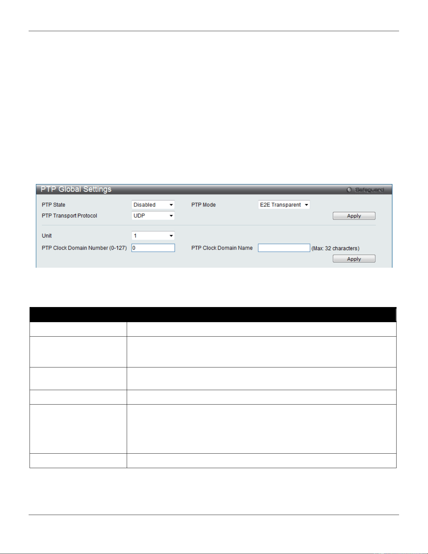
xStack® DGS-3420 Series Layer 2 Managed Stackable Gigabit Switch Web UI Reference Guide
180
PTP is a technology that enables precise synchronization of clocks in systems. PTP is applicable to systems
communicating by local area networks supporting multicast messaging including Ethernet and UDP. PTP enables
heterogeneous systems that include clocks of various inherent precision, resolution and stability to synchronize to a
grandmaster clock.
The synchronization is divided into two processes. The Best Master Clock (BMC) algorithm determines the PTP status
(master/slave) of all local ports. The synchronization algorithm computes the clock offset between the master and slave
clock. There are two mechanisms, Delay Request-response Mechanism and Peer Delay Mechanism, for measuring
the propagation time of an event message.
The PTP system has three types of PTP devices, boundary clock, end-to-end transparent clock and peer-to-peer
transparent clock. Only boundary clock can participate in the selection of the best master clock.
PTP Global Settings
This window is used to configure the PTP function globally.
To view this window, click L2 Features > PTP > PTP Global Settings, as shown below:
Figure 4-123 PTP Global Settings window
The fields that can be configured are described below:
Parameter Description
PTP State
Use the drop-down menu to enable or disable the PTP state.
PTP Mode
Use the drop-down menu to select the PTP device type of the Switch. The Switch
supports three PTP device types, Boundary, P2P Transparent, and E2E
Transparent. The default is E2E Transparent.
PTP Transport Protocol
Use the drop-down menu to select the transport protocol that will be used for the
communication path. The default option is UDP.
Unit
Select the unit you wish to configure.
PTP Clock Domain
Number (0-127)
Enter the domain attribute of the local clock. All PTP messages, data sets, state
machines, and all other PTP entities are always associated with a particular domain
number. The range is from 0 to 127. The default value is 0.
In a stacking system, each unit runs PTP independently, each unit could run in the
same domain or different domains.
PTP Clock Domain Name
Enter the domain name for a specified domain number.
Click the Apply button to accept the changes made for each individual section.
PTP Port Settings
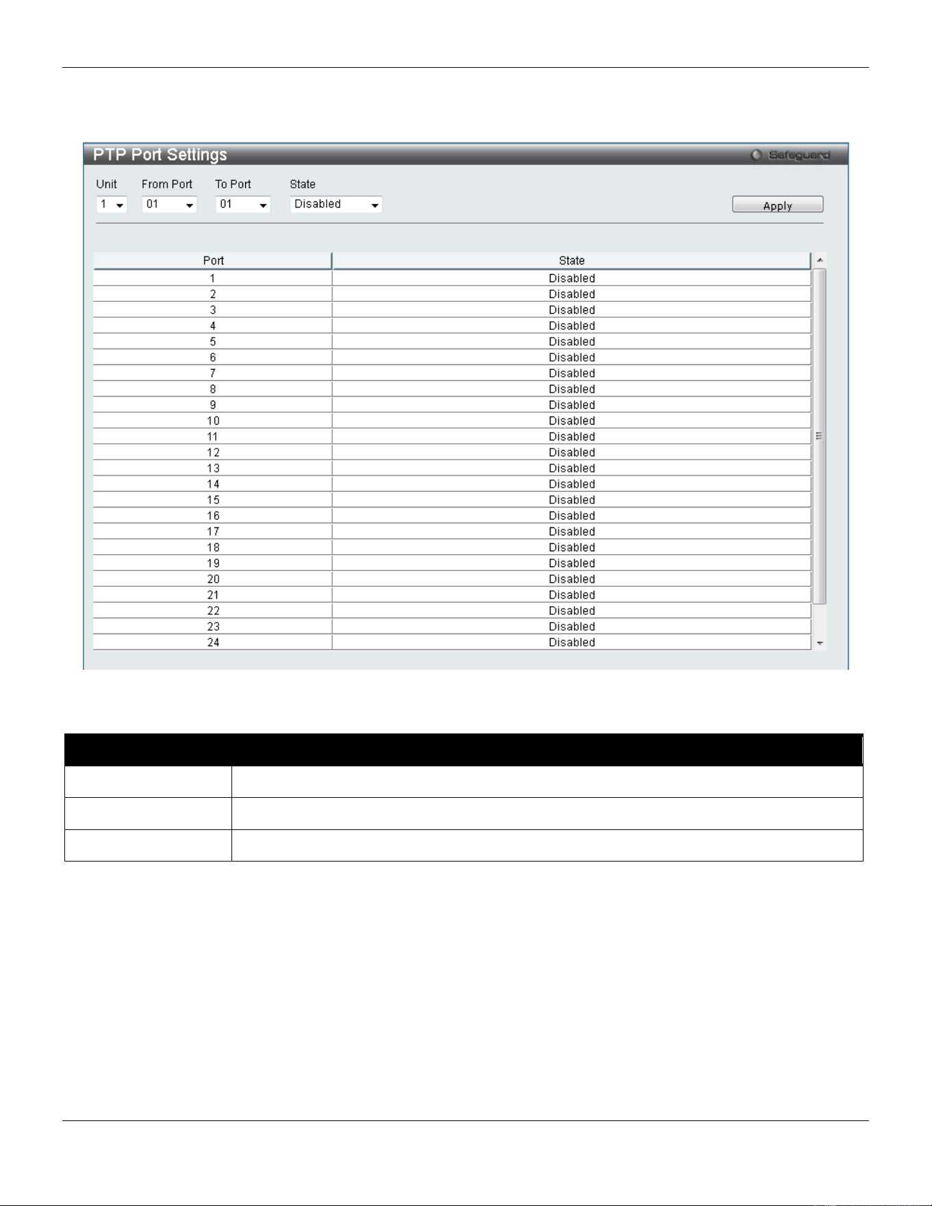
xStack® DGS-3420 Series Layer 2 Managed Stackable Gigabit Switch Web UI Reference Guide
181
This window is used to configure the per port state of the PTP clock.
To view this window, click L2 Features > PTP > PTP Port Settings, as shown below:
Figure 4-124 PTP Port Settings window
The fields that can be configured are described below:
Parameter Description
Unit
Select the unit you wish to configure.
From Port / To Port
Select the port range to use for this configuration.
State
Use the drop-down menu to enable or disable the PTP clock state on the specified ports.
Click the Apply button to accept the changes made.
PTP Boundary Clock Settings
This window is used to configure the PTP boundary clock attributes and requires at least one parameter to execute.
To view this window, click L2 Features > PTP > PTP Boundary Clock Settings, as shown below:
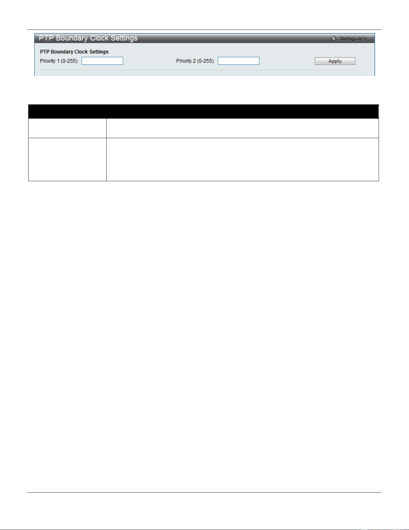
xStack® DGS-3420 Series Layer 2 Managed Stackable Gigabit Switch Web UI Reference Guide
182
Figure 4-125 PTP Boundary Clock Settings window
The fields that can be configured are described below:
Parameter Description
Priority 1 (0-255)
This is used in the execution of the best master clock algorithm. Lower values take
precedence. The range is from 0 to 255. Zero indicates the highest precedence.
Priority 2 (0-255)
This is used in the execution of the best master clock algorithm. Lower values take
precedence. In the event that the operation of the BMC algorithm fails to order the clocks
based on the values of Priority1, the clock’s class and the clock’s accuracy; the Priority 2
will allow the creation of lower values compared to the other devices. The range is from 0
to 255. Zero indicates the highest precedence.
Click the Apply button to accept the changes made.
PTP Boundary Port Settings
This window is used to configure the attributes of the PTP boundary clock. The configuration takes effect when the
PTP device is a boundary type.
To view this window, click L2 Features > PTP > PTP Boundary Port Settings, as shown below:
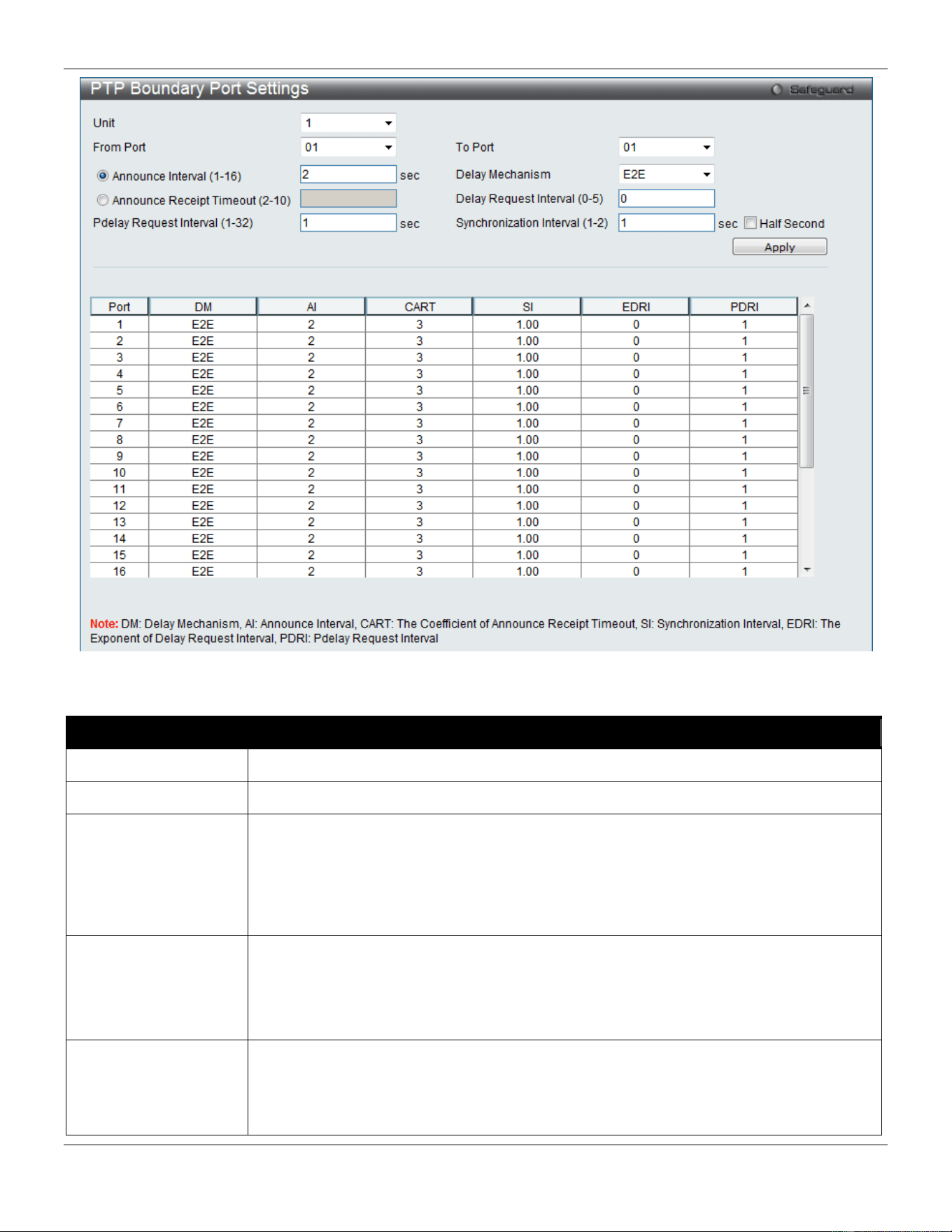
xStack® DGS-3420 Series Layer 2 Managed Stackable Gigabit Switch Web UI Reference Guide
183
Figure 4-126 PTP Boundary Port Settings window
The fields that can be configured are described below:
Parameter Description
Unit
Select the unit you wish to configure.
From Port / To Port
Select the port range to use for this configuration.
Announce Interval (1-
16)
Click the radio button and enter the mean time interval between successive announce
messages. Referred to as the announce interval. In line with the IEEE1588 protocol, the
value of the announce interval is represented as the logarithm to the base 2 of this time
measured in seconds. The entered value should be 1, 2, 4, 8, or 16. If entered an invalid
number, it will be automatically adjusted to allow the bigger and closest value. The
default value is 2 seconds.
Announce Receipt
Timeout (2-10)
Click the radio button and enter the announce interval number that has to pass without
receiving an Announce message before the occurrence of the
ANNOUNCE_RECEIPT_TIMEOUT_EXPIRES event. This value multiplied by the
announce interval value is equal to the interval time of the announce receipt timeout. The
range is from 2 to 10.
Delay Mechanism
Use the drop-down menu to specify the mechanism for measuring the propagation delay
time of an event message.
E2E - The port is configured to use the delay request-response mechanism.
P2P - The peer delay mechanism.
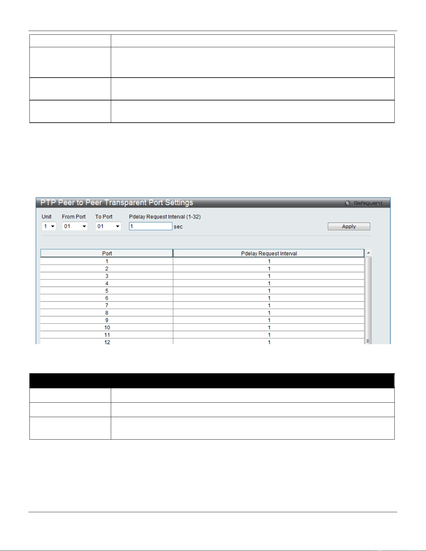
xStack® DGS-3420 Series Layer 2 Managed Stackable Gigabit Switch Web UI Reference Guide
184
The default is E2E.
Delay Request
Interval (0-5)
Enter the permitted mean time interval between successive delay request messages
which are sent by a slave to a specific port on the master. This mean time interval value
is determined and advertised by a master.
Pdelay Request
Interval (1-32)
Enter the permitted mean time interval between successive pdelay_request messages.
Synchronization
Interval (1-2)
Enter the mean time interval between successive Sync messages. Referred to as
syncInterval. Tick the Half Second check box to have the 0.5 second of syncInterval.
Click the Apply button to accept the changes made.
PTP Peer to Peer Transparent Port Settings
This window is used to configure the Pdelay Request Interval of the P2P transparent clock.
To view this window, click L2 Features > PTP > PTP Peer to Peer Transparent Port Settings, as shown below:
Figure 4-127 PTP Peer to Peer Transparent Port Settings window
The fields that can be configured are described below:
Parameter Description
Unit
Select the unit you wish to configure.
From Port / To Port
Select the port range to use for this configuration.
Pdelay Request
Interval (1-32)
Enter the permitted mean time interval between successive Pdelay request messages.
Click the Apply button to accept the changes made.
PTP Clock Information
This window is used to display the active attributes of the PTP clock. When PTP State is disabled in PTP Global
Settings window, PTP Clock Identity displays 0000000000000000.
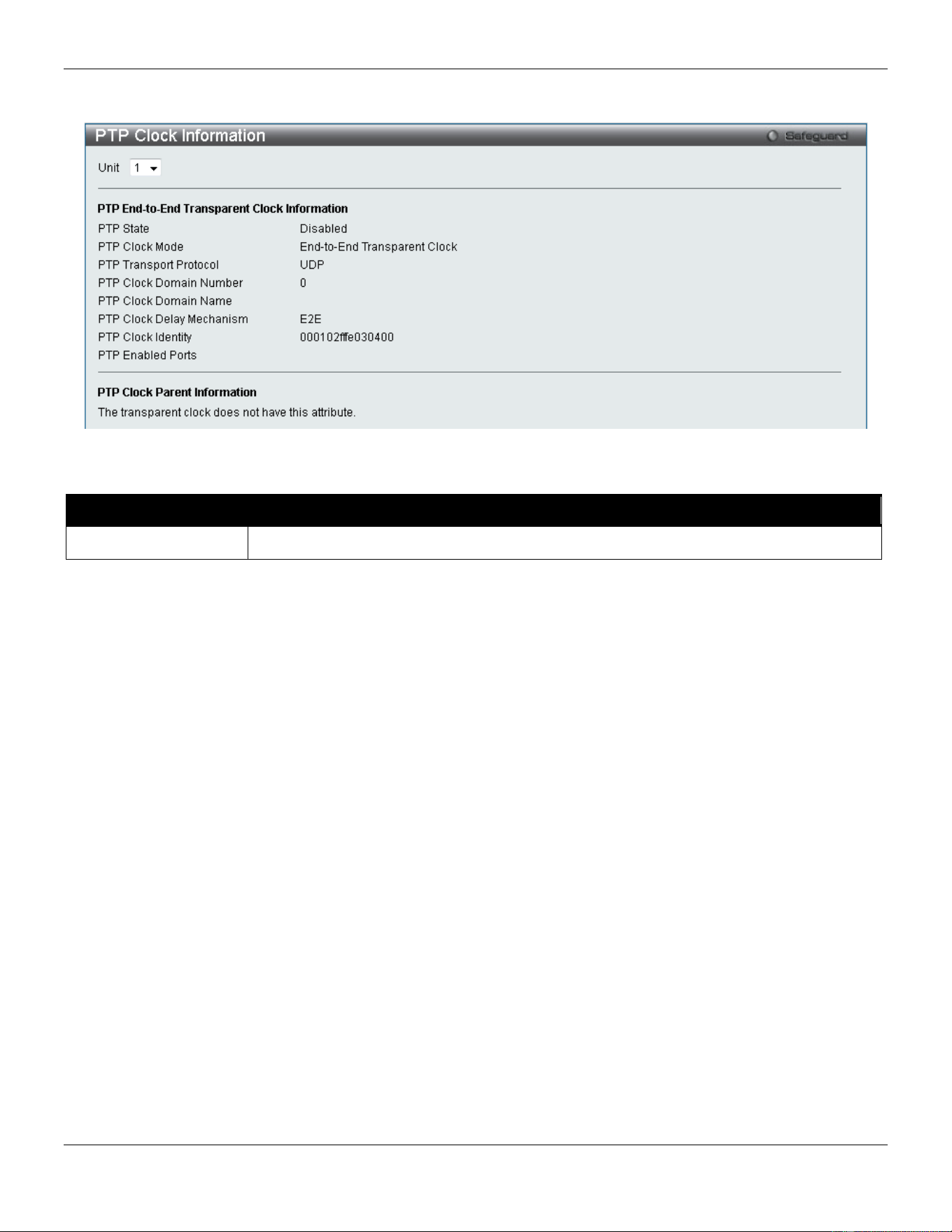
xStack® DGS-3420 Series Layer 2 Managed Stackable Gigabit Switch Web UI Reference Guide
185
To view this window, click L2 Features > PTP > PTP Clock Information, as shown below:
Figure 4-128 PTP Clock Information window
The fields that can be configured are described below:
Parameter Description
Unit
Select the unit you wish to configure.
PTP Port Information
This window is used to display the active attributes of the special PTP ports on the switch.
To view this window, click L2 Features > PTP > PTP Port Information, as shown below:
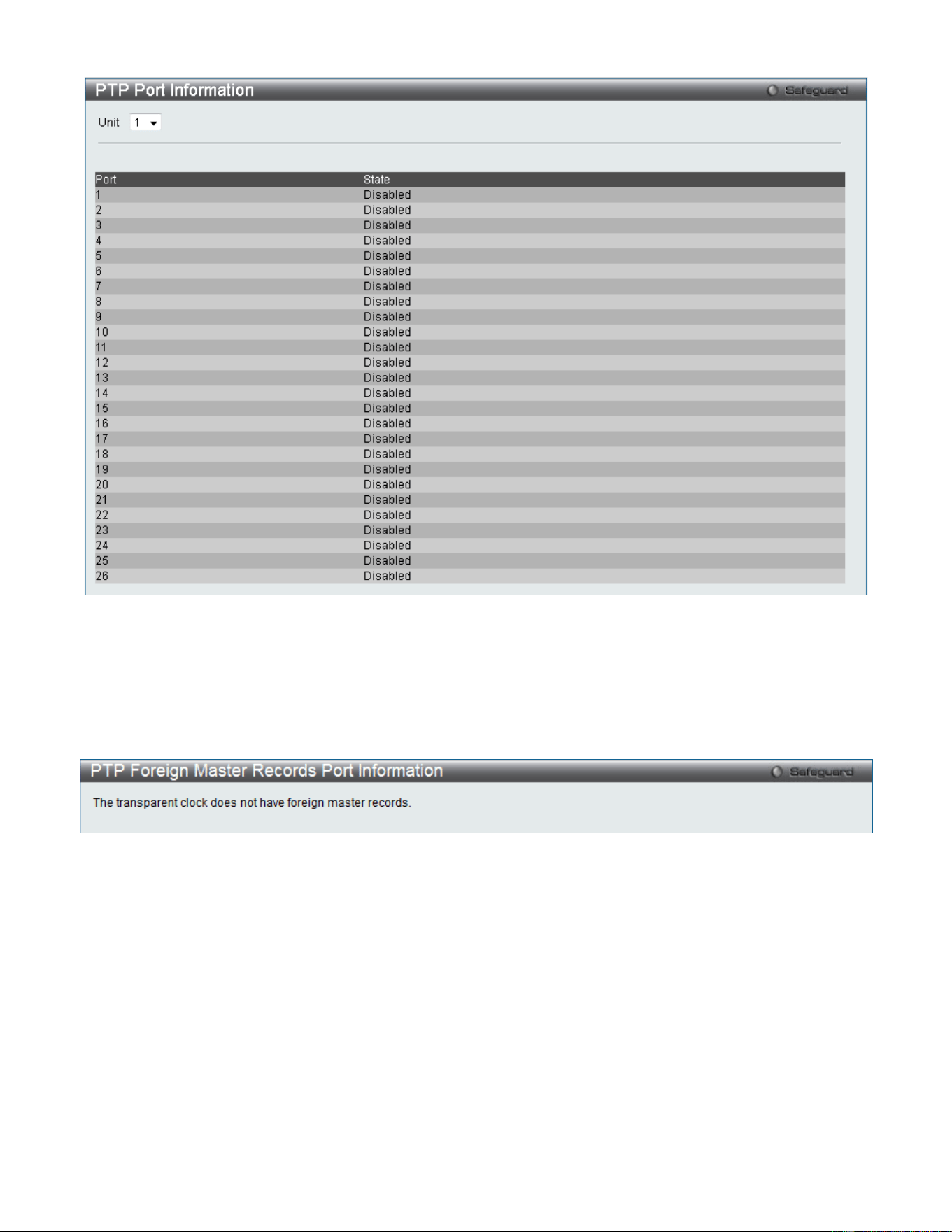
xStack® DGS-3420 Series Layer 2 Managed Stackable Gigabit Switch Web UI Reference Guide
186
Figure 4-129 PTP Port Information window
PTP Foreign Master Records Port Information
This window is used to display the current foreign master data set records of the boundary clock’s special ports.
To view this window, click L2 Features > PTP > PTP Foreign Master Records Port Information, as shown below:
Figure 4-130 PTP Foreign Master Records Port Information window

xStack® DGS-3420 Series Layer 2 Managed Stackable Gigabit Switch Web UI Reference Guide
187
Chapter 5 L3 Features
IPv4 Static/Default Route Settings
IPv4 Route Table
IPv6 Static/Default Route Settings
IPv6 Route Table
Policy Route Settings
IP Forwarding Table
Route Preference Settings
Route Redistribution
IP Tunnel
RIP
VRRP
IPv4 Static/Default Route Settings
The Switch supports static routing for IPv4 formatted addressing. Users can create up to 256 static route entries for
IPv4. For IPv4 static routes, once a static route has been set, the Switch will send an ARP request packet to the next
hop router that has been set by the user. Once an ARP response has been retrieved by the Switch from that next hop,
the route becomes enabled. However, if the ARP entry already exists, an ARP request will not be sent.
The Switch also supports a floating static route, which means that the user may create an alternative static route to a
different next hop. This secondary next hop device route is considered as a backup static route for when the primary
static route is down. If the primary route is lost, the backup route will uplink and its status will become Active.
Entries into the Switch’s forwarding table can be made using both an IP address subnet mask and a gateway.
To view the following window, click L3 Features > IPv4 Static/Default Route Settings, as show below:
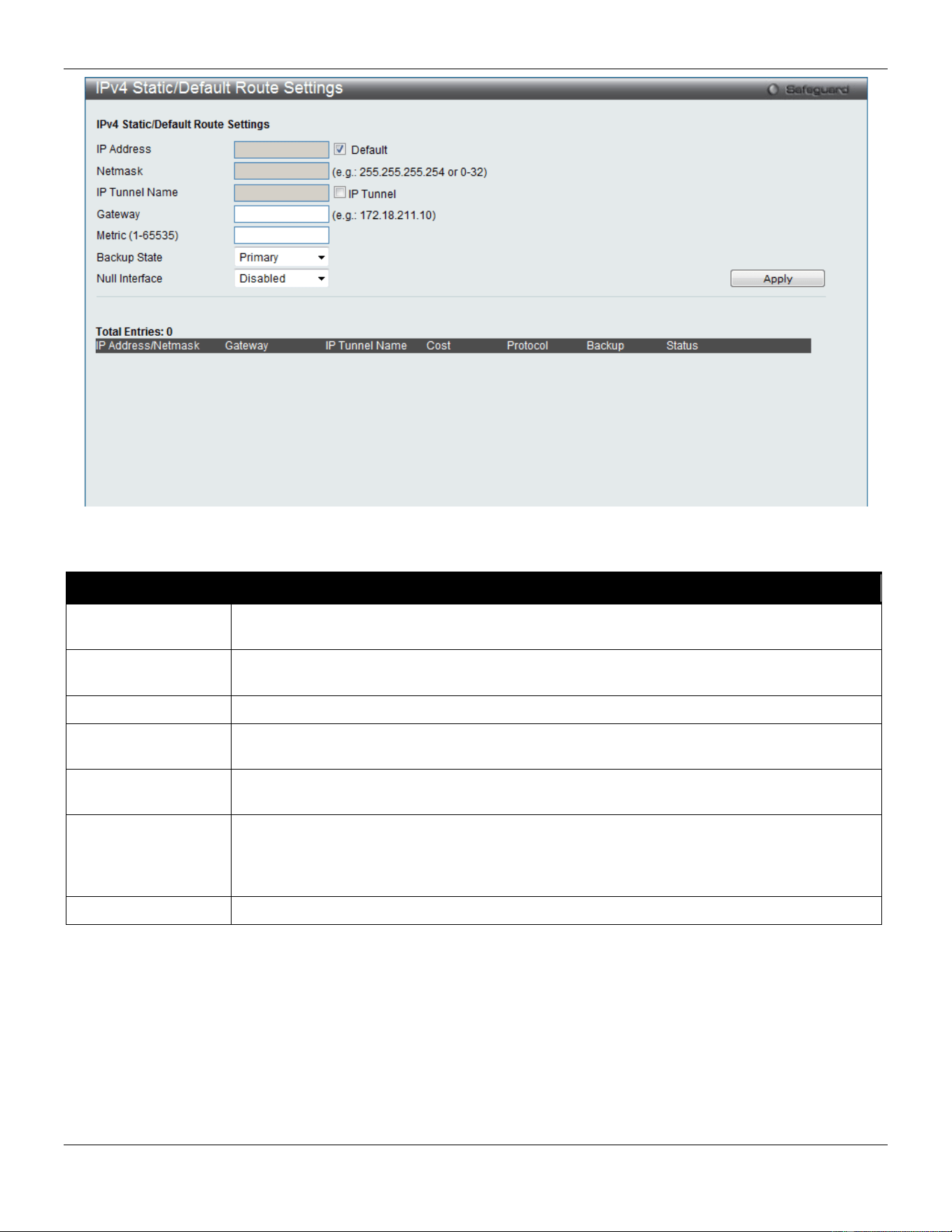
xStack® DGS-3420 Series Layer 2 Managed Stackable Gigabit Switch Web UI Reference Guide
188
Figure 5-1 IPv4 Static/Default Route Settings window
The fields that can be configured are described below:
Parameter Description
IP Address
This field allows the entry of an IPv4 address to be assigned to the static route. Tick the
Default check box to be assigned to the default route.
Netmask
This field allows the entry of a subnet mask to be applied to the corresponding subnet mask
of the IP address.
IP Tunnel Name
Tick the IP Tunnel check box and enter the IP tunnel name used.
Gateway
This field allows the entry of a Gateway IP Address to be applied to the corresponding
gateway of the IP address.
Metric (1-65535)
Represents the metric value of the IP interface entered into the table. This field may read a
number between 1 and 65535.
Backup State
Each IP address can only have one primary route, while other routes should be assigned to
the backup state. When the primary route failed, Switch will try the backup routes according
to the order learnt by the routing table until route success. The field represents the Backup
state that the Static and Default Route is configured for.
Null Interface
Use the drop-down menu to enable or disable the null interface as the next hop.
Click the Apply button to accept the changes made.
IPv4 Route Table
The IP routing table stores all the external routes information of the Switch. This window displays all the external route
information on the Switch.
To view the following window, click L3 Features > IPv4 Route Table, as show below:
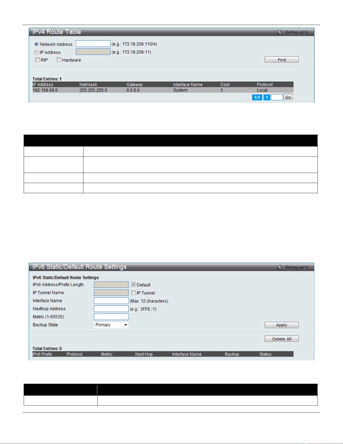
xStack® DGS-3420 Series Layer 2 Managed Stackable Gigabit Switch Web UI Reference Guide
189
Figure 5-2 IPv4 Route Table window
The fields that can be configured are described below:
Parameter Description
Network Address
Enter the destination network address of the route want to be displayed.
IP Address
Enter the destination IP address of the route want to be displayed. The longest prefix
matched route will be displayed.
RIP
Tick the check box to display only RIP routes.
Hardware
Tick the check box to display only the routes that have been written into the chip.
Click the Find button to locate a specific entry based on the information entered.
Enter a page number and click the Go button to navigate to a specific page when multiple pages exist.
IPv6 Static/Default Route Settings
A static entry of an IPv6 address can be entered into the Switch’s routing table for IPv6 formatted addresses.
To view the following window, click L3 Features > IPv6 Static/Default Route Settings, as show below:
Figure 5-3 IPv6 Static/Default Route Settings window
The fields that can be configured are described below:
Parameter Description
IPv6 Address/Prefix
Enter the destination network for the route, or tick the Default check box to be
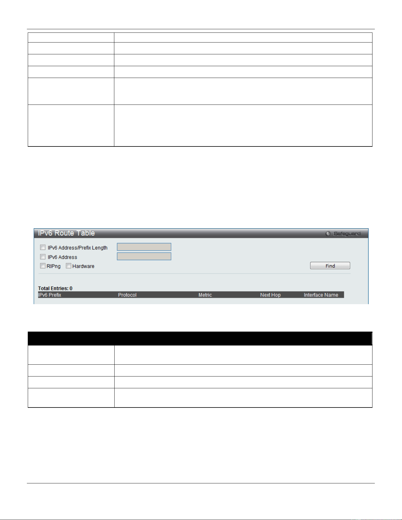
xStack® DGS-3420 Series Layer 2 Managed Stackable Gigabit Switch Web UI Reference Guide
190
Length
assigned to the default route.
IP Tunnel Name
Tick the IP Tunnel check box and enter the IP tunnel name used.
Interface Name
The IP Interface where the static IPv6 route is created.
Nexthop Address
The corresponding IPv6 address for the next hop gateway address in IPv6 format.
Metric (1-65535)
The metric of the IPv6 interface entered into the table representing the number of
routers between the Switch and the IPv6 address above. Metric values allowed are
between 1 and 65535.
Backup State
Each IPv6 address can only have one primary route, while other routes should be
assigned to the backup state. When the primary route failed, the Switch will try the
backup routes according to the order learnt by the routing table until route success.
This field represents the backup state for the IPv6 configured. This field may be
Primary or Backup.
Click the Apply button to accept the changes made.
Click the Delete All button to remove all the entries listed.
IPv6 Route Table
This window is used to display the current IPv6 routing table.
To view the following window, click L3 Features > IPv6 Route Table, as show below:
Figure 5-4 IPv6 Route Table window
The fields that can be configured are described below:
Parameter Description
IPv6 Address/Prefix
Length
Tick the check box and enter the IPv6 destination network address of the route.
IPv6 Address
Tick the check box and enter the IPv6 address.
RIPng
Tick the check box to display the RIPng route entries.
Hardware
Tick the check box to display the route entries which have been written into hardware
table.
Click the Find button to locate a specific entry based on the information entered.
Enter a page number and click the Go button to navigate to a specific page when multiple pages exist.
Policy Route Settings
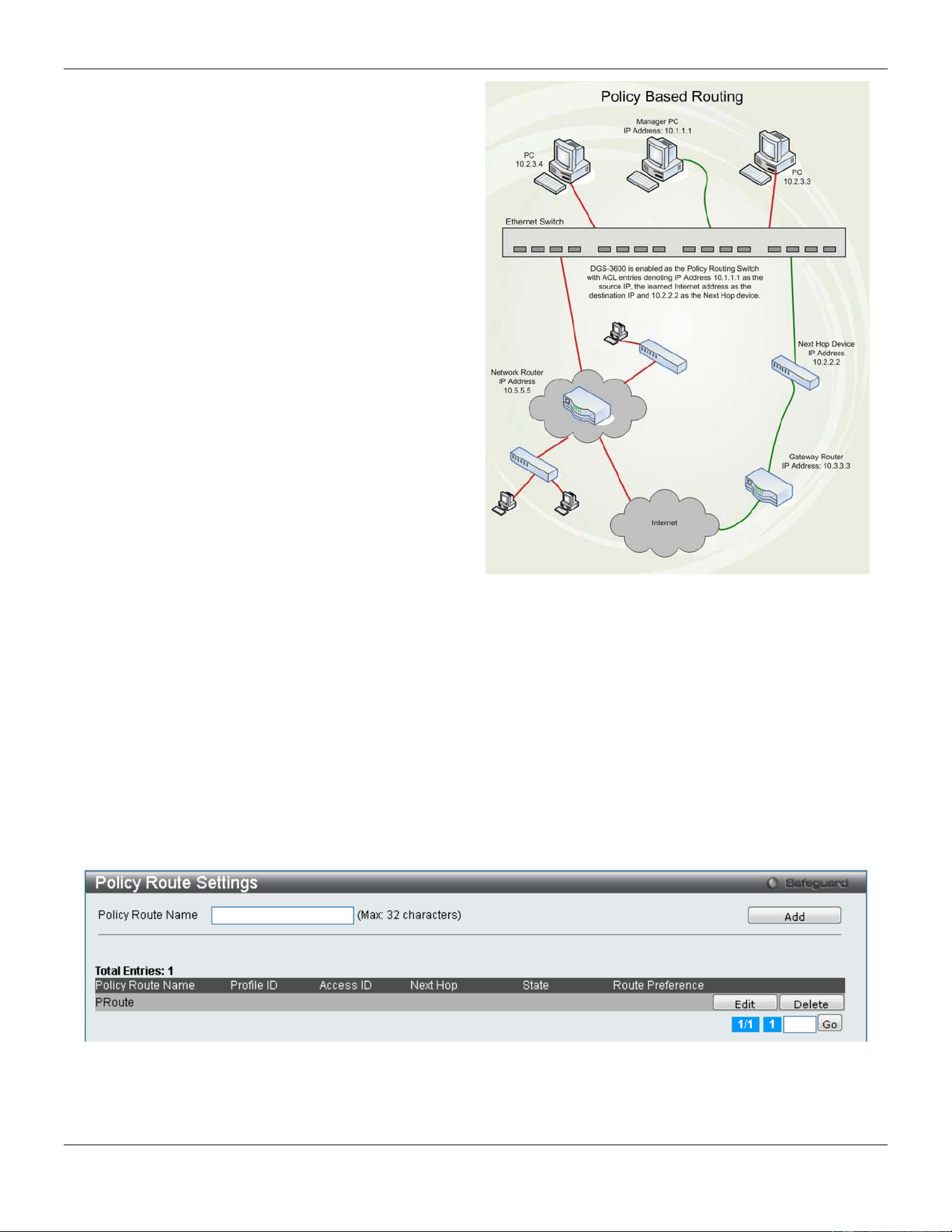
xStack® DGS-3420 Series Layer 2 Managed Stackable Gigabit Switch Web UI Reference Guide
191
Policy Based routing is a method used by the Switch to
give specified devices a cleaner path to the Internet.
Used in conjunction with the Access Profile feature, the
Switch will identify traffic originating from a device
using the Access Profile feature and forward it on to a
next hop router that has a more direct connection to
the Internet than the normal routing scheme of your
network.
Take the example adjacent picture. Let’s say that the
PC with IP address 10.1.1.1 belongs to the manager of
a company while the other PCs belong to employees.
The network administrator hopes to circumvent
network traffic by configuring the Policy Routing Switch
to make a more direct connection to the Internet using
a next hop router (10.2.2.2) that is directly attached to
a Gateway router (10.3.3.3), thus totally avoiding the
normal network and its related traffic. To accomplish
this, the user must configure the Access Profile feature
of the Switch to have the PC, with IP address 10.1.1.1
as the Source IP address and the Internet address as
the destination IP address (learned through routing
protocols), along with other pertinent information. Next,
the administrator must configure the Policy Route
window to be enabled for this Access Profile and its
associated rule, and the Next Hop Router’s IP address
(10.2.2.2) must be set. Finally, this Policy Route entry
must be enabled.
Figure 5-5 Policy Base Routing Example window
Once completed, the Switch will identify the IP address using the Access Profile function, recognize that is has a
Policy Based route, and then forward the information on to the specified next hop router, that will, in turn, relay
packets to the gateway router. Thus, the new, cleaner path to the Internet has been formed.
There are some restrictions and cautions when implementing this feature:
1. The access profile must first be created, along with the accompanying rule. If the administrator attempts to
enable this feature without the access profile, an error message will be produced.
2. If the access profile is configured as Deny, the packet will be dropped and not forwarded to the next hop
destination.
3. If the administrator deletes a rule or profile that is directly linked to a configured policy route, and error
message will be prompted to the administrator.
To view the following window, click L3 Features > Policy Route Settings, as shown below:
Figure 5-6 Policy Route Settings window
Click the Add button to add a new entry based on the information entered.
Click the Edit button to re-configure the specific entry.
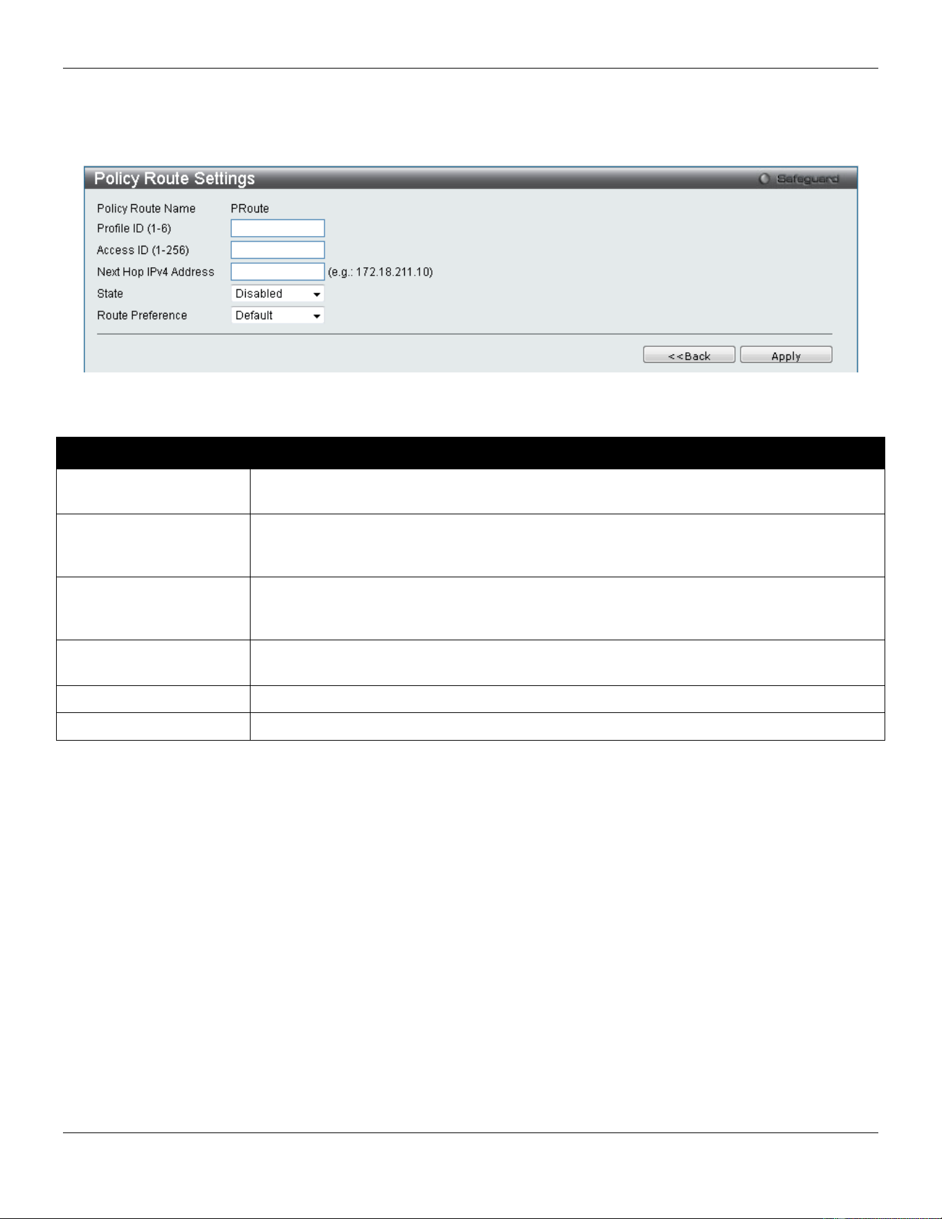
xStack® DGS-3420 Series Layer 2 Managed Stackable Gigabit Switch Web UI Reference Guide
192
Click the Delete button to remove the specific entry.
Enter a page number and click the Go button to navigate to a specific page when multiple pages exist.
After clicking the Edit button, the following page will appear:
Figure 5-7 Policy Route Settings window
The fields that can be configured are described below:
Parameter Description
Policy Route Name
Enter a name of no more than 32 alphanumeric characters that will be used to identify this
policy route.
Profile ID (1-6)
Enter the Profile ID number of the Access Profile, previously created, which will be used to
identify packets as following this Policy Route. This access profile, along with the access
rule, must first be constructed before this policy route can be created.
Access ID (1-256)
Enter the Access ID number of the Access Rule, previously created, which will be used to
identify packets as following this Policy Route. This access rule, along with the access
profile, must first be constructed before this policy route can be created.
Next Hop IPv4 Address
This is the IP address of the Next Hop router that will have a direct connection to the
gateway router connected to the Internet.
State
Use the pull-down menu to enable or disable this Policy Route.
Route Preference
Select the route preference used here. Options to choose from are Default and BPR.
Click the Apply button to accept the changes made.
Click the <<Back button to discard the changes made and return to the previous page.
IP Forwarding Table
The IP forwarding table stores all the direct connected IP information. On this page the user can view all the direct
connected IP information.
To view the following window, click L3 Features > IP Forwarding Table, as show below:
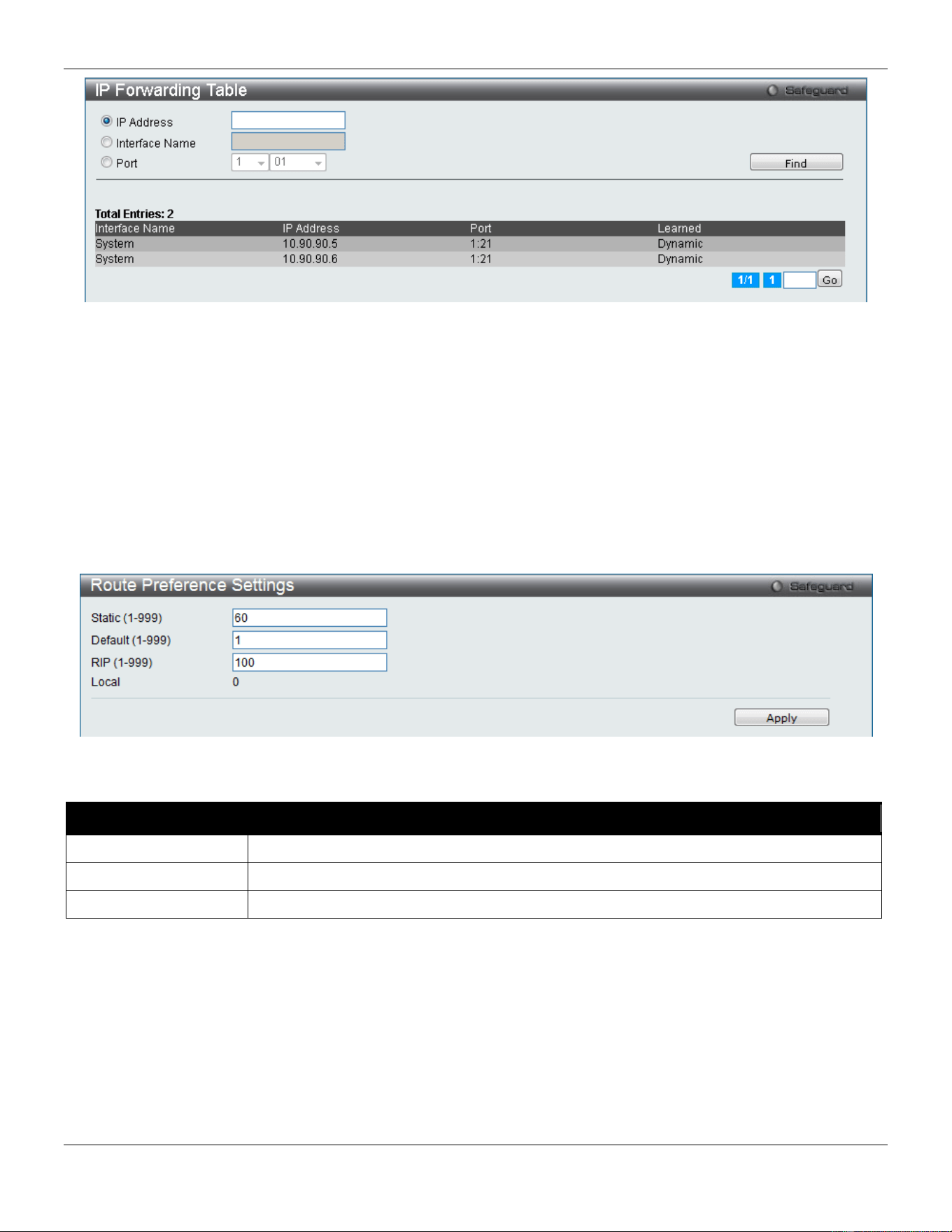
xStack® DGS-3420 Series Layer 2 Managed Stackable Gigabit Switch Web UI Reference Guide
193
Figure 5-8 IP Forwarding Table
Click the IP Address, Interface Name or Port radio button, enter the information and click the Find button to locate a
specific entry based on the information entered.
Enter a page number and click the Go button to navigate to a specific page when multiple pages exist.
Route Preference Settings
This window is used to configure the route type preference. The route with smaller preference has higher priority. The
preference for local routes is fixed to 0.
To view the following window, click L3 Features > Route Preference Settings, as shown below:
Figure 5-9 Route Preference Settings window
The fields that can be configured are described below:
Parameter Description
Static
Enter the Static route type preference value here.
Default
Enter the Default route type preference value here.
RIP
Enter the RIP route type preference value here.
Click the Apply button to accept the changes made.
Route Redistribution
Route Redistribution Settings
This page is used to configure redistribute routing information from one routing protocols to another.
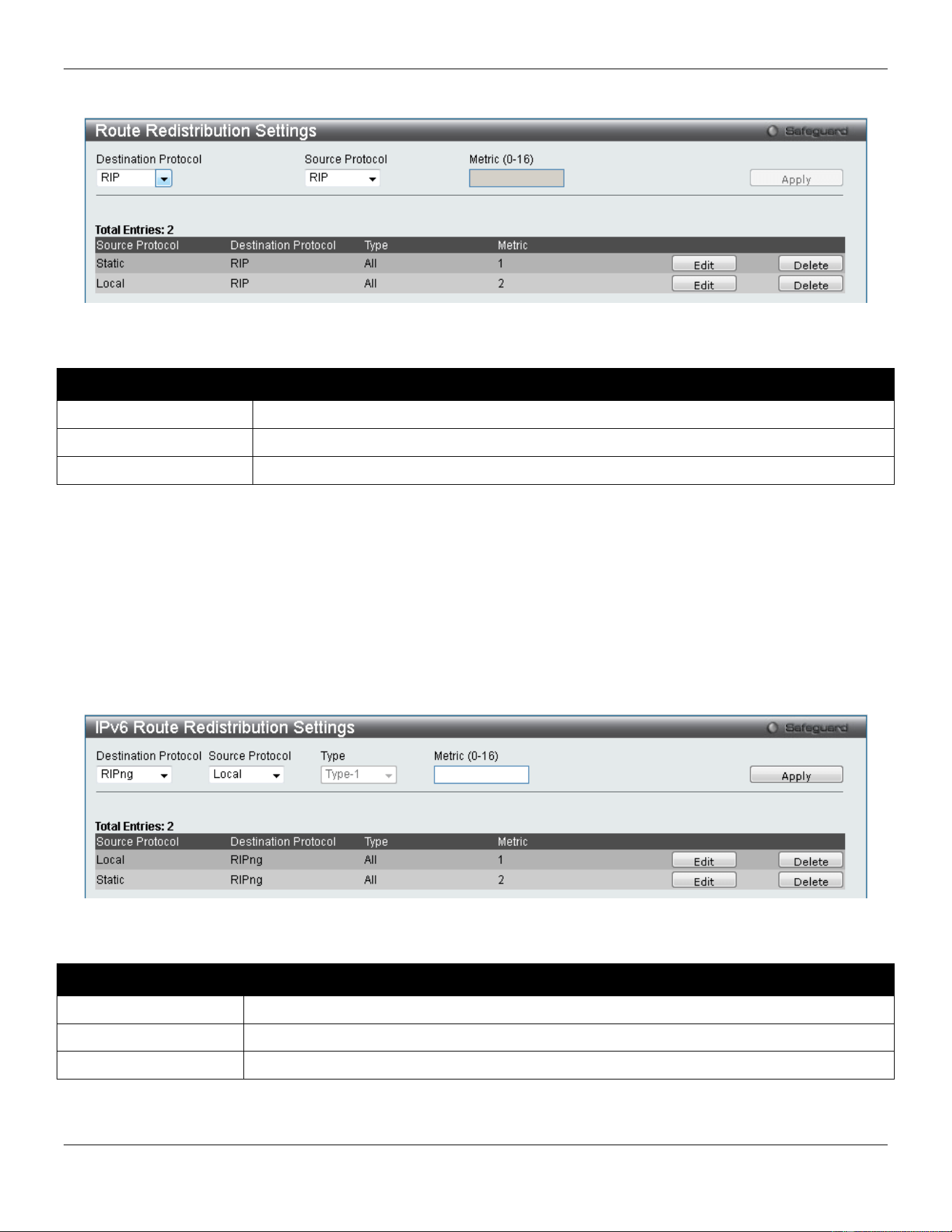
xStack® DGS-3420 Series Layer 2 Managed Stackable Gigabit Switch Web UI Reference Guide
194
To view the following window, click L3 Features > Route Redistribution > Route Redistribution Settings, as shown
below:
Figure 5-10 Route Redistribution Settings window
The fields that can be configured are described below:
Parameter Description
Destination Protocol
Specifies the destination protocol.
Source Protocol
Specifies the source protocol. Options to choose from are RIP, Static and Local.
Metric (0-16)
Specifies the metric value for the redistributed routes.
Click the Apply button to accept the changes made.
Click the Edit button to re-configure the specified entry.
Click the Delete button to remove the specified entry.
IPv6 Route Redistribution Settings
Here the user can configure the IPv6 route redistribution settings.
To view the following window, click L3 Features > Route Redistribution > IPv6 Route Redistribution Settings, as
shown below:
Figure 5-11 IPv6 Route Redistribution Settings window
The fields that can be configured are described below:
Parameter Description
Destination Protocol
Select the destination protocol used here.
Source Protocol
Select the source protocol used here. Options to choose from are Local, and Static.
Metric
Enter the metric value for this entry here.
Click the Apply button to accept the changes made.
Click the Edit button to re-configure the specified entry.
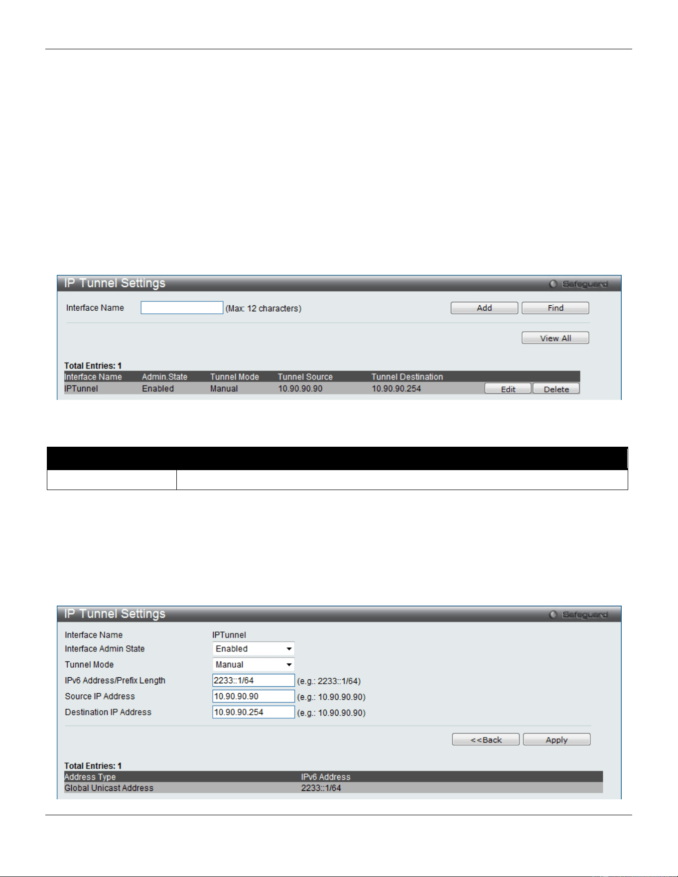
xStack® DGS-3420 Series Layer 2 Managed Stackable Gigabit Switch Web UI Reference Guide
195
Click the Delete button to remove the specified entry.
IP Tunnel
The Switch supports IP tunneling. The idea behind this feature is to be able to integrate IPv6 into and coexist with
existing IPv4 networks. It is expected that IPv4 and IPv6 hosts will need to coexist for a substantial time during the
steady migration from IPv4 to IPv6, and the development of transition strategies, tools, and mechanisms has been part
of the basic IPv6 design from the start. This IPv6 tunneling mechanism is one of D-Link’s strategies for solving the
transition from IPv4 to IPv6.
IP Tunnel Settings
This window is used to configure IP Tunnel Settings.
To view the following window, click L3 Features > IP Tunnel > IP Tunnel Settings, as shown below:
Figure 5-12 IP Tunnel Settings window
The fields that can be configured are described below:
Parameter Description
Interface Name
Enter the IP tunnel interface name.
Click the Add button to add a new entry based on the information entered.
Click the Find button to locate a specific entry based on the information entered.
Click the View All button to display all the existing entries.
Click the Edit button to re-configure the specific entry.
Click the Delete button to remove the specific entry.
Click the Edit button to see the following window.
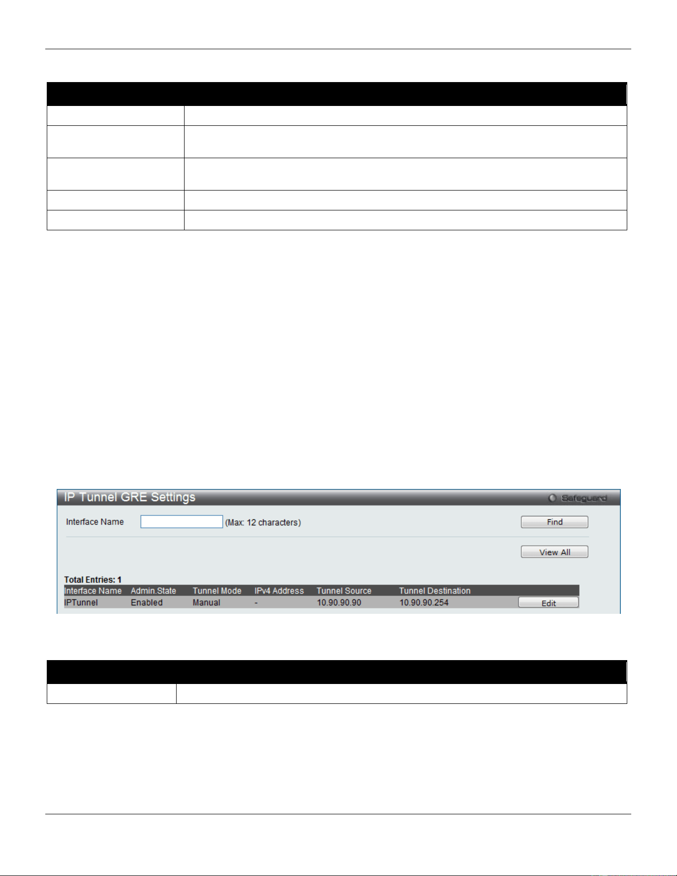
xStack® DGS-3420 Series Layer 2 Managed Stackable Gigabit Switch Web UI Reference Guide
196
Figure 5-13 IP tunnel Settings - Edit window
The fields that can be configured are described below:
Parameter Description
Interface Admin State
Use the drop-down menu to enable or disable the interface admin state.
Tunnel Mode Use the drop-down menu to select the tunnel modes. Available selections are None,
Manual, 6to4, and ISATAP.
IPv6 Address/Prefix
Length
Enter the IPv6 network address.
Source IP Address
Enter the source IP address.
Destination IP Address
Enter the destination IP address.
Click the <<Back button to return to the previous window.
Click the Apply button to accept the changes made for each individual section.
IP Tunnel GRE Settings
This window is used to configure an existing tunnel as a GRE tunnel (IPv6/IPv4-in-IPv4 or IPv6/IPv4-in-IPv6) on the
Switch. If this tunnel has been configured in another mode before, the tunnel’s information will still exist in the database.
However, whether the tunnel’s former information is valid or not, it depends on the current mode.
GRE tunnels are simple point-to-point tunnels that can be used within a site or between sites.
When a user wants to configure a GRE IPv6/IPv4-in-IPv4 tunnel, both the source and destination address must be
IPv4 addresses because the delivery protocol is the IPv4 protocol. If the source and destination address type are not
consistent, then the GRE tunnel will not work.
When a user wants to configure a GRE IPv6/IPv4-in-IPv6 tunnel, both the source and destination address must be
IPv6 addresses because the delivery protocol is the IPv6 protocol. If the source and destination address type are not
consistent then the GRE tunnel will not work.
To view the following window, click L3 Features > IP Tunnel > IP Tunnel GRE Settings, as shown below:
Figure 5-14 IP Tunnel GRE Settings window
The fields that can be configured are described below:
Parameter Description
Interface Name
Enter the IP tunnel interface name.
Click the Find button to locate a specific entry based on the information entered.
Click the View All button to display all the existing entries.
Click the Edit button to re-configure the specific entry.
Click the Edit button to see the following window.
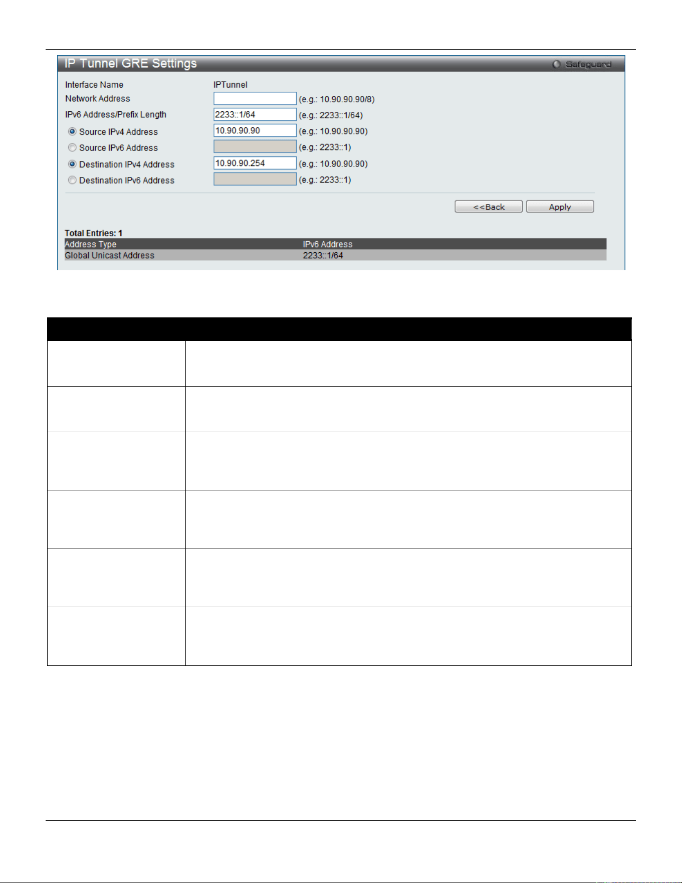
xStack® DGS-3420 Series Layer 2 Managed Stackable Gigabit Switch Web UI Reference Guide
197
Figure 5-15 IP tunnel GRE Settings – Edit window
The fields that can be configured are described below:
Parameter Description
Network Address
Enter the IPv4 network address assigned to the GRE tunnel interface. IPv4 processing
will be enabled on the IPv4 tunnel interface when an IPv4 address is configured. This
IPv4 address is not connected with the tunnel source or destination IPv4 address.
IPv6 Address/Prefix
Length
Enter the IPv6 network address assigned to the GRE tunnel interface. IPv6 processing
will be enabled on the IPv6 tunnel interface when an IPv6 address is configured. This
IPv6 address is not connected with the tunnel source or destination IPv4 address.
Source IPv4 Address
Click the radio button and enter the source IPv4 address of the GRE tunnel interface. It
is used as the source address for packets in the tunnel. The address type that will be
used depends on the Delivery Protocol. The address type used at both the source and
destination must be consistent, otherwise, the GRE tunnel will not work.
Source IPv6 Address
Click the radio button and enter the source IPv6 address of the GRE tunnel interface. It
is used as the source address for packets in the tunnel. The address type that will be
used depends on the Delivery Protocol. The address type used at both the source and
destination must be consistent, otherwise, the GRE tunnel will not work.
Destination IPv4
Address
Click the radio button and enter the destination IPv4 address of the GRE tunnel
interface. It is used as the destination address for packets in the tunnel. The address
type that will be used depends on the Delivery Protocol. The address type used at both
the source and destination must be consistent, otherwise, the GRE tunnel will not work.
Destination IPv6
Address
Click the radio button and enter the destination IPv6 address of the GRE tunnel
interface. It is used as the destination address for packets in the tunnel. The address
type that will be used depends on the Delivery Protocol. The address type used at both
the source and destination must be consistent, otherwise, the GRE tunnel will not work.
Click the <<Back button to return to the previous window.
Click the Apply button to accept the changes made for each individual section.

xStack® DGS-3420 Series Layer 2 Managed Stackable Gigabit Switch Web UI Reference Guide
198
RIP
The Routing Information Protocol is a distance-vector routing protocol. There are two types of network devices running
RIP - active and passive. Active devices advertise their routes to others through RIP messages, while passive devices
listen to these messages. Both active and passive routers update their routing tables based upon RIP messages that
active routers exchange. Only routers can run RIP in the active mode.
Every 30 seconds, a router running RIP broadcasts a routing update containing a set of pairs of network addresses
and a distance (represented by the number of hops or routers between the advertising router and the remote network).
So, the vector is the network address and the distance is measured by the number of routers between the local router
and the remote network.
RIP measures distance by an integer count of the number of hops from one network to another. A router is one hop
from a directly connected network, two hops from a network that can be reached through a router, etc. The more
routers between a source and a destination, the greater the RIP distance (or hop count).
There are a few rules to the routing table update process that help to improve performance and stability. A router will
not replace a route with a newly learned one if the new route has the same hop count (sometimes referred to as ‘cost’).
So learned routes are retained until a new route with a lower hop count is learned.
When learned routes are entered into the routing table, a timer is started. This timer is restarted every time this route is
advertised. If the route is not advertised for a period of time (usually 180 seconds), the route is removed from the
routing table.
RIP does not have an explicit method to detect routing loops. Many RIP implementations include an authorization
mechanism (a password) to prevent a router from learning erroneous routes from unauthorized routers.
To maximize stability, the hop count RIP uses to measure distance must have a low maximum value. Infinity (that is,
the network is unreachable) is defined as 16 hops. In other words, if a network is more than 16 routers from the source,
the local router will consider the network unreachable.
RIP can also be slow to converge (to remove inconsistent, unreachable or looped routes from the routing table)
because RIP messages propagate relatively slowly through a network.
Slow convergence can be solved by using split horizon update, where a router does not propagate information about a
route back to the interface on which it was received. This reduces the probability of forming transient routing loops.
Hold down can be used to force a router to ignore new route updates for a period of time (usually 5 seconds) after a
new route update has been received. This allows all routers on the network to receive the message.
A router can ‘poison reverse’ a route by adding an infinite (16) hop count to a route’s advertisement. This is usually
used in conjunction with triggered updates, which force a router to send an immediate broadcast when an update of an
unreachable network is received.
RIP Version 1 Message Format
There are two types of RIP messages: routing information messages and information requests. Both types use the
same format.
The Command field specifies an operation according the following table:
Command Description

xStack® DGS-3420 Series Layer 2 Managed Stackable Gigabit Switch Web UI Reference Guide
199
1
Request for partial or full routing information.
2
Response containing network-distance pairs from sender’s routing table.
3
Turn on trace mode.
4
Turn off trace mode.
5
Reserved for Sun Microsystems internal use.
9
Update Request.
10
Update Response.
11
Update Acknowledgement
RIP Command Codes
The field VERSION contains the protocol version number (1 in this case), and is used by the receiver to verify which
version of RIP the packet was sent.
RIP 1 Message
RIP is not limited to TCP/IP. Its address format can support up to 14 octets (when using IP, the remaining 10 octets
must be zeros). Other network protocol suites can be specified in the Family of Source Network field (IP has a value of
2). This will determine how the address field is interpreted.
RIP specifies that the IP address, 0.0.0.0, denotes a default route.
The distances, measured in router hops are entered in the Distance to Source Network, and Distance to Destination
Network fields.
RIP 1 Route Interpretation
RIP was designed to be used with classed address schemes, and does not include an explicit subnet mask. An
extension to version 1 does allow routers to exchange subnet addresses, but only if the subnet mask used by the
network is the same as the subnet mask used by the address. This means the RIP version 1 cannot be used to
propagate classless addresses.
Routers running RIP version 1 must send different update messages for each IP interface to which it is connected.
Interfaces that use the same subnet mask as the router’s network can contain subnet routes, other interfaces cannot.
The router will then advertise only a single route to the network.
RIP Version 2 Extensions
RIP version 2 includes an explicit subnet mask entry, so RIP version 2 can be used to propagate variable length
subnet addresses or CIDR classless addresses. RIP version 2 also adds an explicit next hop entry, which speeds
convergence and helps prevent the formation of routing loops.
RIP2 Message Format
The message format used with RIP2 is an extension of the RIP1 format. RIP version 2 also adds a 16-bit route tag that
is retained and sent with router updates. It can be used to identify the origin of the route. Because the version number
in RIP2 occupies the same octet as in RIP1, both versions of the protocols can be used on a given router
simultaneously without interference.
RIP Settings
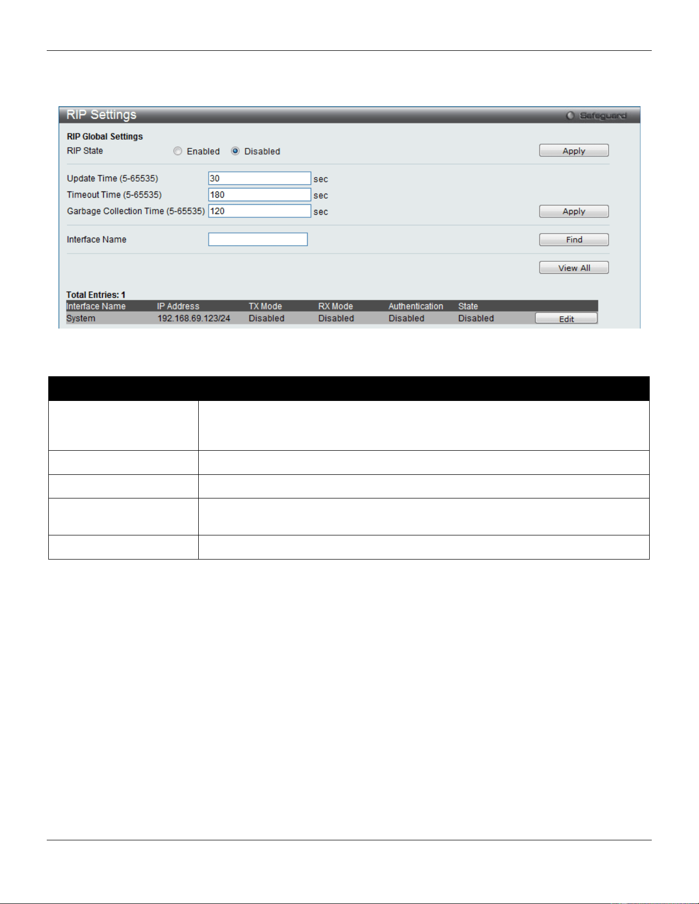
xStack® DGS-3420 Series Layer 2 Managed Stackable Gigabit Switch Web UI Reference Guide
200
This window is used to configure the RIP settings for one or more IP interfaces.
To view the following window, click L3 Features > RIP > RIP Settings, as shown below:
Figure 5-16 RIP Settings window
The fields that can be configured are described below:
Parameter Description
RIP State
Specifies that the RIP state will be enabled or disabled. If the state is disabled, then
RIP packets will not be either transmitted or received by the interface. The network
configured on this interface will not be in the RIP database.
Update Time (5-65535)
Enter the value of the rate at which RIP updates are sent.
Timeout Time (5-65535)
Enter the value of the time after which a RIP route is declared to be invalid.
Garbage Collection Time
(5-65535)
Enter the value of the time for which a RIP route will be kept before it is removed from
routing table.
Interface Name
Specifies the IP interface name used for this configuration.
Click the Apply button to accept the changes made for each individual section.
Click the Find button to find the specified entry.
Click the View All button to view all the entries.
Click the Edit button to re-configure the selected entry.
After clicking the Edit button, the following window will appear.
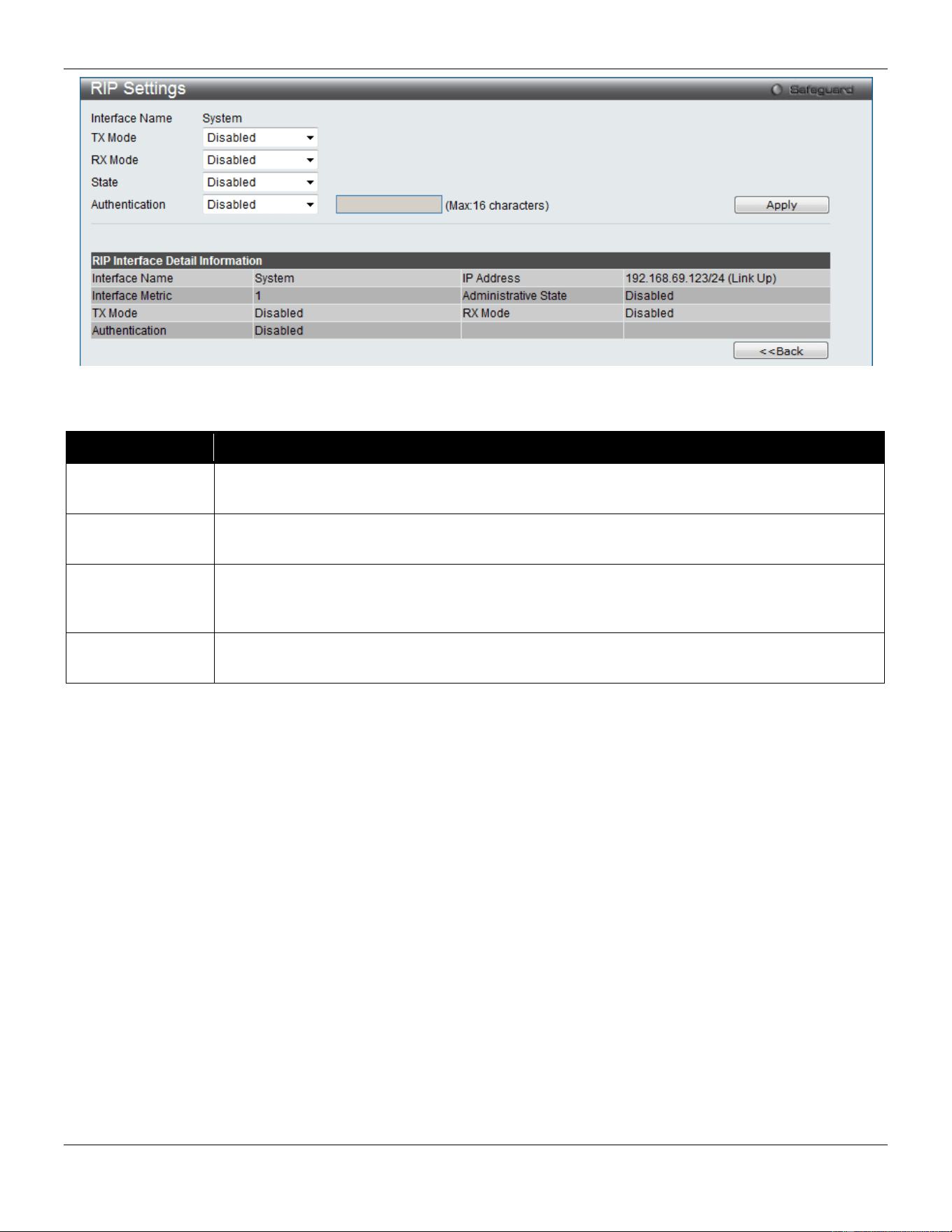
xStack® DGS-3420 Series Layer 2 Managed Stackable Gigabit Switch Web UI Reference Guide
201
Figure 5-17 RIP Settings – Edit window
The fields that can be configured are described below:
Parameter Description
TX Mode Specifies the RIP transmission mode. Options to choose from are v1 Only, v1 Compatible
and v2 Only. Select Disable to disable this option.
RX Mode Specifies the RIP receive mode Options to choose from are v1 Only, v2 Only and v1 or v2.
Select Disable to disable this option.
State
Specifies that the RIP state will be enabled or disabled. If the state is disabled, then RIP
packets will not be either transmitted or received by the interface. The network configured on
this interface will not be in the RIP database.
Authentication
Specifies to set the state of authentication. When the authentication state is enabled, enter the
password used in the space provided.
Click the Apply button to accept the changes made.
Click the <<Back button to return to the previous window.
RIPng
The Switch supports Routing Information Protocol next generation (RIPng). RIPng is a routing protocol that exchanges
routing information used to compute routes and is intended for IPv6-based networks.
RIPng Global Settings
This window allows users to set up RIPng.
To view the following window, click L3 Features > RIP>RIPng > RIPng Global Settings, as shown below:
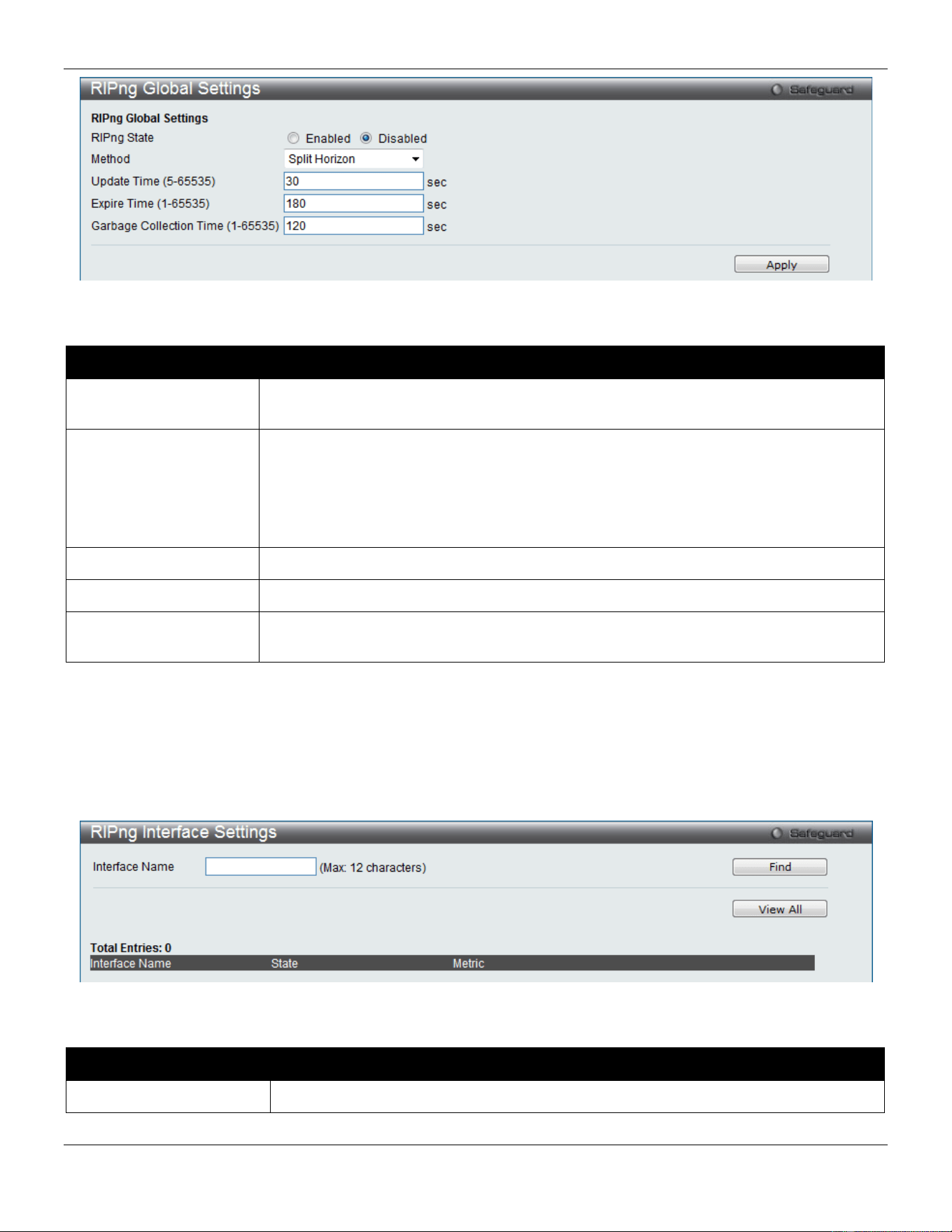
xStack® DGS-3420 Series Layer 2 Managed Stackable Gigabit Switch Web UI Reference Guide
202
Figure 5-18 RIPng Global Settings window
The fields that can be configured are described below:
Parameter Description
RIPng State
Click the radio buttons to enable or disable RIPng globally. The default setting is
Disabled.
Method Use the drop-down menu to choose from No Horizon, Split Horizon, and Poison
Reverse.
No Horizon – Configured to not use any horizon.
Split Horizon – Configured to use basic split horizon. This is the default setting.
Poison Reverse – Configured to use split horizon with poison reverse.
Update Time (5-65535)
Enter the value, in seconds, of the update timer.
Expire Time (1-65535)
Enter the interval, in seconds, of the expire timer.
Garbage Collection
Time (1-65535)
Enter the value, in seconds, of the garbage collection timer.
Click the Apply button to accept the changes made.
RIPng Interface Settings
This window allows users to configure RIPng interface settings.
To view the following window, click L3 Features > RIP>RIPng > RIPng Interface Settings, as shown below:
Figure 5-19 RIPng Interface Settings window
The fields that can be configured are described below:
Parameter Description
Interface Name
Enter the interface name for the RIPng configuration.
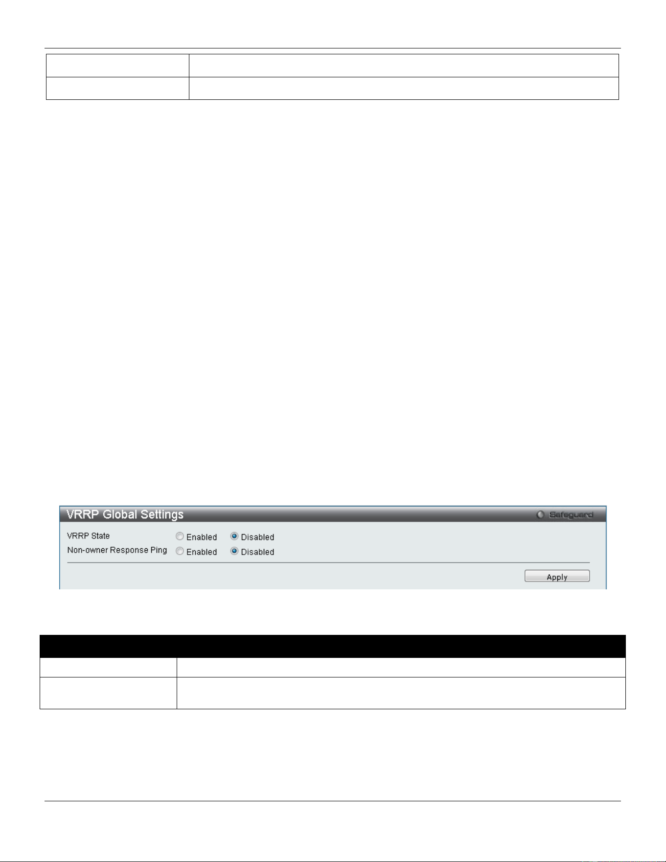
xStack® DGS-3420 Series Layer 2 Managed Stackable Gigabit Switch Web UI Reference Guide
203
State
Modifies the state of the RIPng entry.
Metric
Modifies the metric value of the RIPng entry.
Click the Find button to find the interface entered.
Click the View All button to view all the interfaces configured on this switch.
Click the Edit button to re-configure the selected entry.
VRRP
Virtual Routing Redundancy Protocol (VRRP) is a function on the Switch that dynamically assigns responsibility for a
virtual router to one of the VRRP routers on a LAN. The VRRP router that controls the IP address associated with a
virtual router is called the Master, and will forward packets sent to this IP address. This will allow any Virtual Router IP
address on the LAN to be used as the default first hop router by end hosts. Utilizing VRRP, the administrator can
achieve a higher available default path cost without needing to configure every end host for dynamic routing or routing
discovery protocols.
Statically configured default routes on the LAN are prone to a single point of failure. VRRP is designed to eliminate
these failures by setting an election protocol that will assign a responsibility for a virtual router to one of the VRRP
routers on the LAN. When a virtual router fails, the election protocol will select a virtual router with the highest priority to
be the Master router on the LAN. This retains the link and the connection is kept alive, regardless of the point of failure.
To configure VRRP for virtual routers on the Switch, an IP interface must be present on the system and it must be a
part of a VLAN. VRRP IP interfaces may be assigned to every VLAN, and therefore IP interface, on the Switch. VRRP
routers within the same VRRP group must be consistent in configuration settings for this protocol to function optimally.
VRRP Global Settings
This window is used to configure the VRRP Global settings for this switch.
To view the following window, click L3 Features > VRRP > VRRP Global Settings, as shown below:
Figure 5-20 VRRP Global Settings window
The fields that can be configured are described below:
Parameter Description
VRRP State
Specifies whether the VRRP Global state is enabled or disabled.
Non-owner Response
Ping
Specifies that the virtual IP address is allowed to be pinged from other host end nodes to
verify connectivity.
Click the Apply button to accept the changes made.
VRRP Virtual Router Settings
This window is used to configure the VRRP virtual router settings.
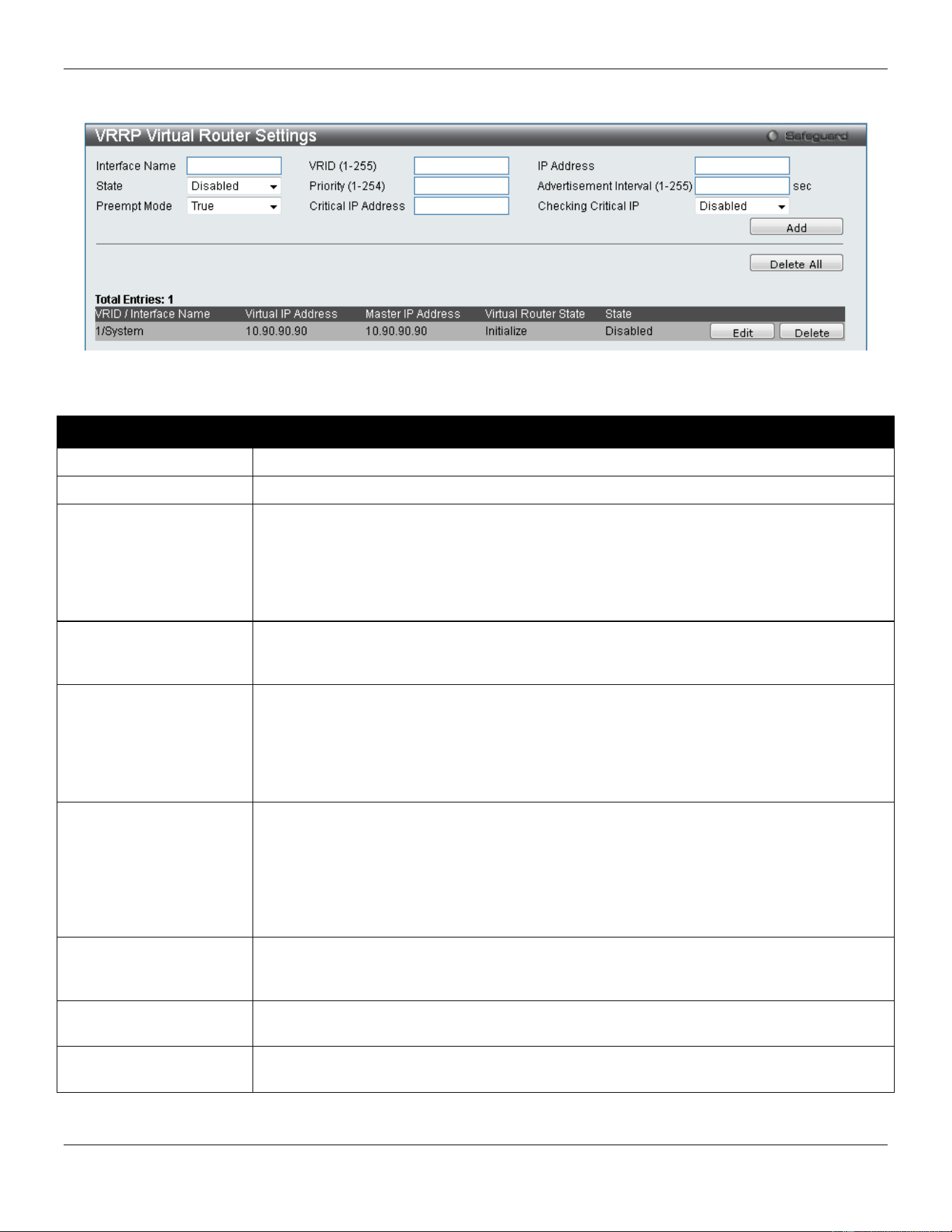
xStack® DGS-3420 Series Layer 2 Managed Stackable Gigabit Switch Web UI Reference Guide
204
To view the following window, click L3 Features > VRRP > VRRP Virtual Router Settings, as shown below:
Figure 5-21 VRRP Virtual Router Settings window
The fields that can be configured are described below:
Parameter Description
Interface Name
Specifies the IP interface name used to create a VRRP entry.
State
Specifies the state of the virtual router function of the interface.
Preempt Mode
This entry will determine the behavior of backup routers within the VRRP group by
controlling whether a higher priority backup router will preempt a lower priority Master
router. A True entry, along with having the backup router’s priority set higher than the
masters priority, will set the backup router as the Master router. A False entry will disable
the backup router from becoming the Master router. This setting must be consistent with
all routers participating within the same VRRP group.
VRID (1-255)
Specifies the ID of the Virtual Router used. All routers participating in this group must be
assigned the same VRID value. This value must be different from other VRRP groups set
on the Switch.
Priority (1-254)
Specifies the priority to be used for the Virtual Router Master election process. The VRRP
Priority value may determine if a higher priority VRRP router overrides a lower priority
VRRP router. A higher priority will increase the probability that this router will become the
Master router of the group. A lower priority will increase the probability that this router will
become the backup router. VRRP routers that are assigned the same priority value will
elect the highest physical IP address as the Master router.
Critical IP Address
Specifies an IP address of the physical device that will provide the most direct route to the
Internet or other critical network connections from this virtual router. This must be a real IP
address of a real device on the network. If the connection from the virtual router to this IP
address fails, the virtual router will automatically disabled. A new Master will be elected
from the backup routers participating in the VRRP group. Different critical IP addresses
may be assigned to different routers participating in the VRRP group, and can therefore
define multiple routes to the Internet or other critical network connections.
IP Address
Specifies the virtual router’s IP address used. This IP address is also the default gateway
that will be statically assigned to end hosts and must be set for all routers that participate
in this group.
Advertisement Interval
(1-255)
Specifies the time interval used between sending advertisement messages.
Checking Critical IP
Specifies the state of checking the status (active or inactive) of a critical IP address.
Options to choose from are Enabled and Disabled.
Click the Add button to add a new entry.
Click the Delete All button to remove all the entries listed.
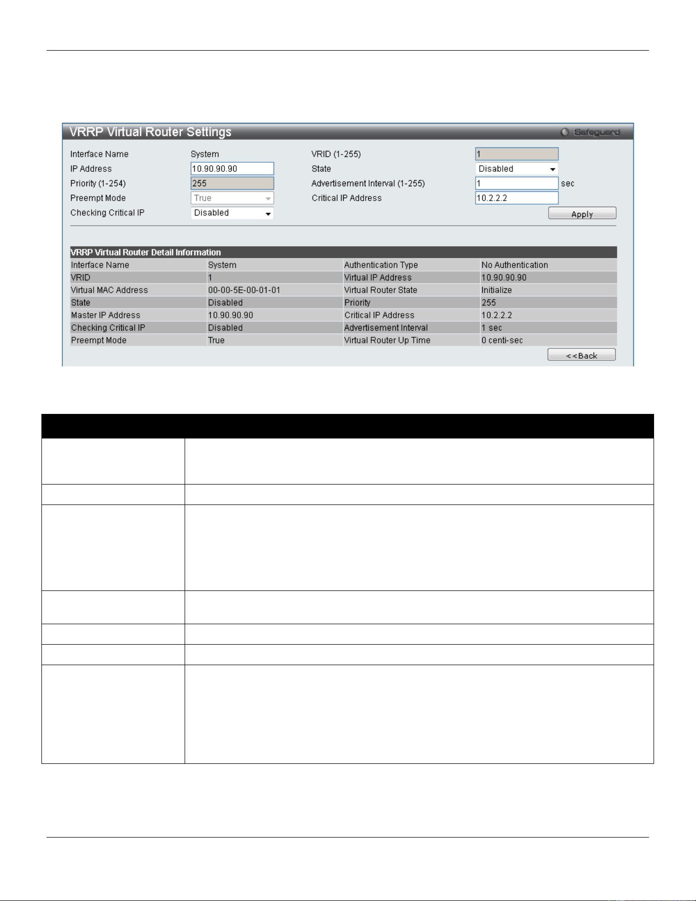
xStack® DGS-3420 Series Layer 2 Managed Stackable Gigabit Switch Web UI Reference Guide
205
Click the Edit button to re-configure a specific entry listed.
Click the Delete button to remove a specific entry listed.
After clicking the Edit button, the following page with be displayed.
Figure 5-22 VRRP Virtual Router Settings window
The fields that can be configured are described below:
Parameter Description
IP Address
Specifies the virtual router’s IP address used. This IP address is also the default gateway
that will be statically assigned to end hosts and must be set for all routers that participate
in this group.
Priority
Specifies the priority to be used for the Virtual Router Master election process
Preempt Mode
This entry will determine the behavior of backup routers within the VRRP group by
controlling whether a higher priority backup router will preempt a lower priority Master
router. A True entry, along with having the backup router’s priority set higher than the
masters priority, will set the backup router as the Master router. A False entry will disable
the backup router from becoming the Master router. This setting must be consistent with
all routers participating within the same VRRP group.
Checking Critical IP
Specifies the state of checking the status (active or inactive) of a critical IP address.
Options to choose from are Enabled and Disabled.
State
Specifies the state of the virtual router function of the interface.
Advertisement Interval
Specifies the time interval used between sending advertisement messages.
Critical IP Address
Specifies an IP address of the physical device that will provide the most direct route to the
Internet or other critical network connections from this virtual router. This must be a real IP
address of a real device on the network. If the connection from the virtual router to this IP
address fails, the virtual router will automatically disabled. A new Master will be elected
from the backup routers participating in the VRRP group. Different critical IP addresses
may be assigned to different routers participating in the VRRP group, and can therefore
define multiple routes to the Internet or other critical network connections.
Click the Apply button to accept the changes made.
Click on the <<Back button to return to the previous window.
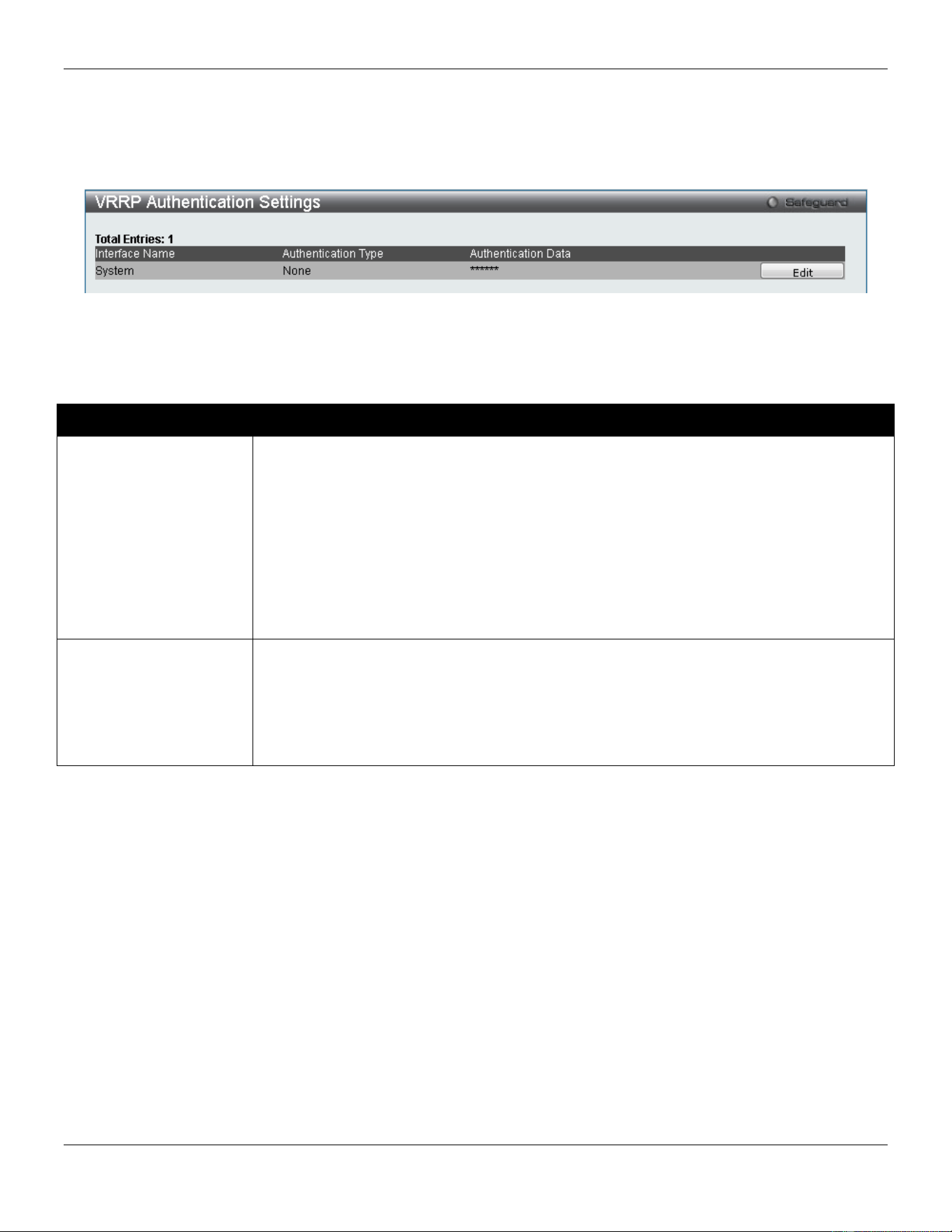
xStack® DGS-3420 Series Layer 2 Managed Stackable Gigabit Switch Web UI Reference Guide
206
VRRP Authentication Settings
This window is used to configure a virtual router authentication type on an interface.
To view the following window, click L3 Features > VRRP > VRRP Authentication Settings, as shown below:
Figure 5-23 VRRP Authentication Settings window
Click the Edit button to re-configure a specific entry listed.
The fields that can be configured are described below:
Parameter Description
Authentication Type Specifies the VRRP’s authentication type. Options to choose from are None, Simple and
IP.
None - Selecting this parameter indicates that VRRP protocol exchanges will not be
authenticated.
Simple - Selecting this parameter will require the user to set a simple password in the
Auth. Data field for comparing VRRP message packets received by a router. If the two
passwords are not exactly the same, the packet will be dropped.
IP - Selecting this parameter will require the user to set an IP for authentication in
comparing VRRP messages received by the router. If the two values are inconsistent, the
packet will be dropped.
Authentication Data Specifies the authentication data used in the Simple and IP authentication algorithm. This
entry must be consistent with all routers participating in the same IP interface.
Simple - Simple will require the user to enter an alphanumeric string of no more than eight
characters to identify VRRP packets received by a router.
IP - IP will require the user to enter an alphanumeric string of no more than sixteen
characters to identify VRRP packets received by a router.
Click the Apply button to accept the changes made.
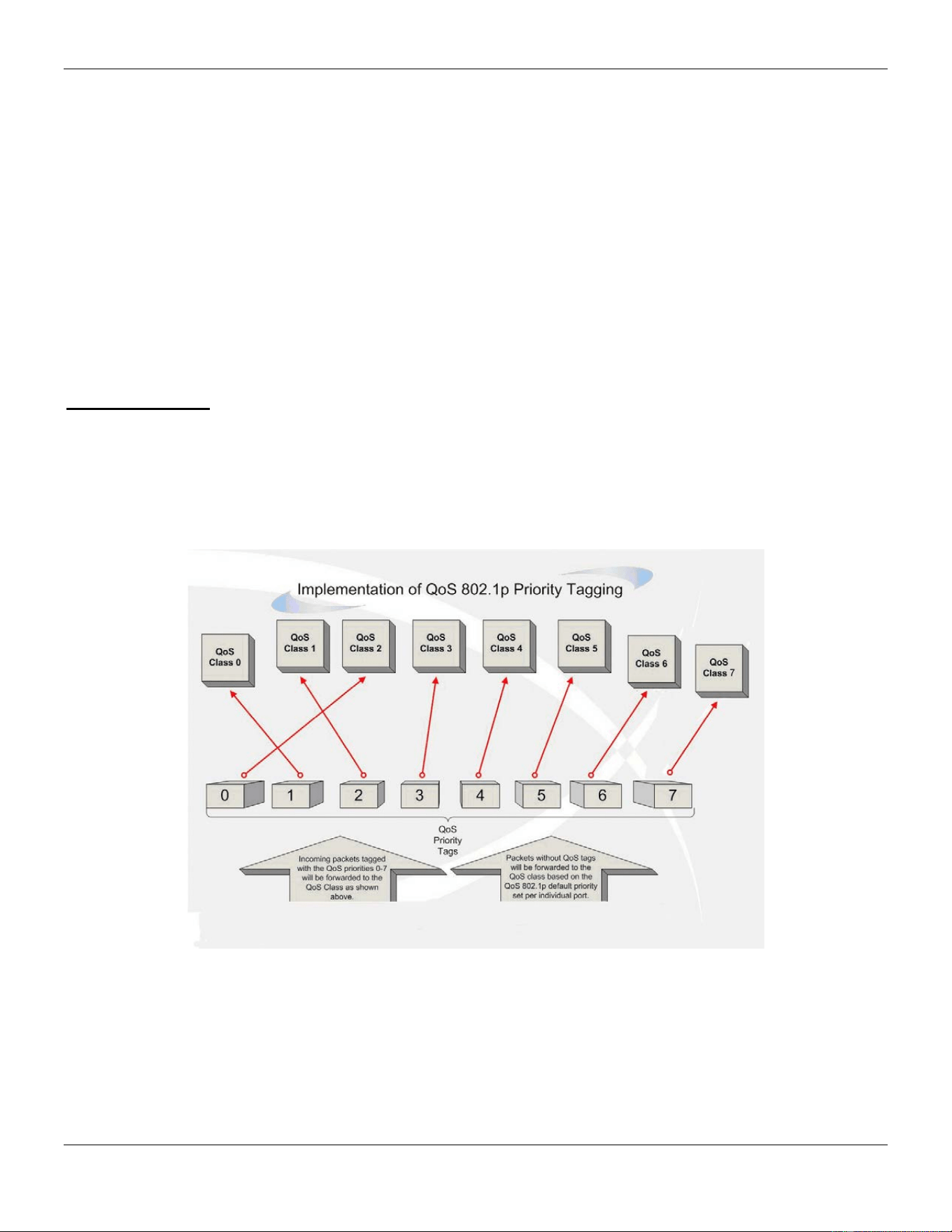
xStack® DGS-3420 Series Layer 2 Managed Stackable Gigabit Switch Web UI Reference Guide
207
Chapter 6 QoS
802.1p Settings
Bandwidth Control
Traffic Control Settings
DSCP
HOL Blocking Prevention
Scheduling Settings
WRED
The Switch supports 802.1p priority queuing Quality of Service. The following section discusses the implementation of
QoS (Quality of Service) and benefits of using 802.1p priority queuing.
Advantages of QoS
QoS is an implementation of the IEEE 802.1p standard that allows network administrators a method of reserving
bandwidth for important functions that require a large bandwidth or have a high priority, such as VoIP (voice-over
Internet Protocol), web browsing applications, file server applications or video conferencing. Not only can a larger
bandwidth be created, but other less critical traffic can be limited, so excessive bandwidth can be saved. The Switch
has separate hardware queues on every physical port to which packets from various applications can be mapped to,
and, in turn prioritized. View the following map to see how the Switch implements basic 802.1P priority queuing.
Figure 6-1 Mapping QoS on the Switch
The picture above shows the default priority setting for the Switch. Class-7 has the highest priority of the seven priority
classes of service on the Switch. In order to implement QoS, the user is required to instruct the Switch to examine the
header of a packet to see if it has the proper identifying tag. Then the user may forward these tagged packets to
designated classes of service on the Switch where they will be emptied, based on priority.
For example, let’s say a user wishes to have a video conference between two remotely set computers. The
administrator can add priority tags to the video packets being sent out, utilizing the Access Profile commands. Then, on

xStack® DGS-3420 Series Layer 2 Managed Stackable Gigabit Switch Web UI Reference Guide
208
the receiving end, the administrator instructs the Switch to examine packets for this tag, acquires the tagged packets
and maps them to a class queue on the Switch. Then in turn, the administrator will set a priority for this queue so that
will be emptied before any other packet is forwarded. This result in the end user receiving all packets sent as quickly as
possible, thus prioritizing the queue and allowing for an uninterrupted stream of packets, which optimizes the use of
bandwidth available for the video conference.
Understanding QoS
The Switch supports 802.1p priority queuing. The Switch has eight priority queues. These priority queues are
numbered from 7 (Class 7) — the highest priority queue — to 0 (Class 0) — the lowest priority queue. The eight priority
tags specified in IEEE 802.1p (p0 to p7) are mapped to the Switch’s priority queues as follows:
• Priority 0 is assigned to the Switch’s Q2 queue.
• Priority 1 is assigned to the Switch’s Q0 queue.
• Priority 2 is assigned to the Switch’s Q1 queue.
• Priority 3 is assigned to the Switch’s Q3 queue.
• Priority 4 is assigned to the Switch’s Q4 queue.
• Priority 5 is assigned to the Switch’s Q5 queue.
• Priority 6 is assigned to the Switch’s Q6 queue.
• Priority 7 is assigned to the Switch’s Q7 queue.
For strict priority-based scheduling, any packets residing in the higher priority classes of service are transmitted first.
Multiple strict priority classes of service are emptied based on their priority tags. Only when these classes are empty,
are packets of lower priority transmitted.
For weighted round-robin queuing, the number of packets sent from each priority queue depends upon the assigned
weight. For a configuration of eight CoS queues, A~H with their respective weight value: 8~1, the packets are sent in
the following sequence: A1, B1, C1, D1, E1, F1, G1, H1, A2, B2, C2, D2, E2, F2, G2, A3, B3, C3, D3, E3, F3, A4, B4,
C4, D4, E4, A5, B5, C5, D5, A6, B6, C6, A7, B7, A8, A1, B1, C1, D1, E1, F1, G1, H1.
For weighted round-robin queuing, if each CoS queue has the same weight value, then each CoS queue has an equal
opportunity to send packets just like round-robin queuing.
For weighted round-robin queuing, if the weight for a CoS is set to 0, then it will continue processing the packets from
this CoS until there are no more packets for this CoS. The other CoS queues that have been given a nonzero value,
and depending upon the weight, will follow a common weighted round-robin scheme.
Remember that the Switch has eight configurable priority queues (and eight Classes of Service) for each port on the
Switch.
802.1p Settings
802.1p Default Priority Settings
The Switch allows the assignment of a default 802.1p priority to each port on the Switch. This page allows the user to
assign a default 802.1p priority to any given port on the switch that will insert the 802.1p priority tag to untagged
packets received. The priority and effective priority tags are numbered from 0, the lowest priority, to 7, the highest
priority. The effective priority indicates the actual priority assigned by RADIUS. If the RADIUS assigned value exceeds
the specified limit, the value will be set at the default priority. For example, if the RADIUS assigns a limit of 8 and the
default priority is 0, the effective priority will be 0.
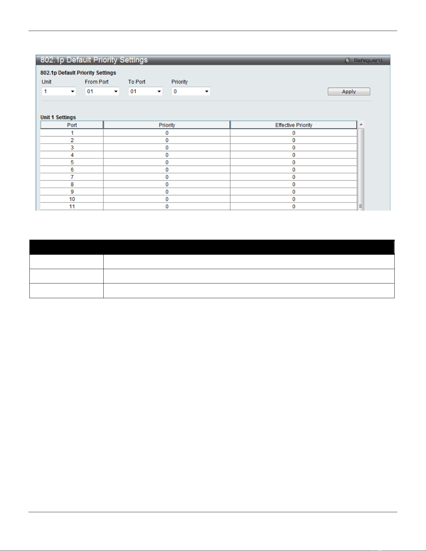
xStack® DGS-3420 Series Layer 2 Managed Stackable Gigabit Switch Web UI Reference Guide
209
To view the following window, click QoS > 802.1p Settings > 802.1p Default Priority Settings, as show below:
Figure 6-2 Default Priority Settings window
The fields that can be configured are described below:
Parameter Description
Unit
Select the unit you wish to configure.
From Port / To Port
Select the starting and ending ports to use.
Priority Use the drop-down menu to select a value from 0 to 7.
Click the Apply button to accept the changes made.
802.1p User Priority Settings
The Switch allows the assignment of a class of service to each of the 802.1p priorities.
To view the following window, click QoS > 802.1p Settings > 802.1p User Priority Settings, as show below:
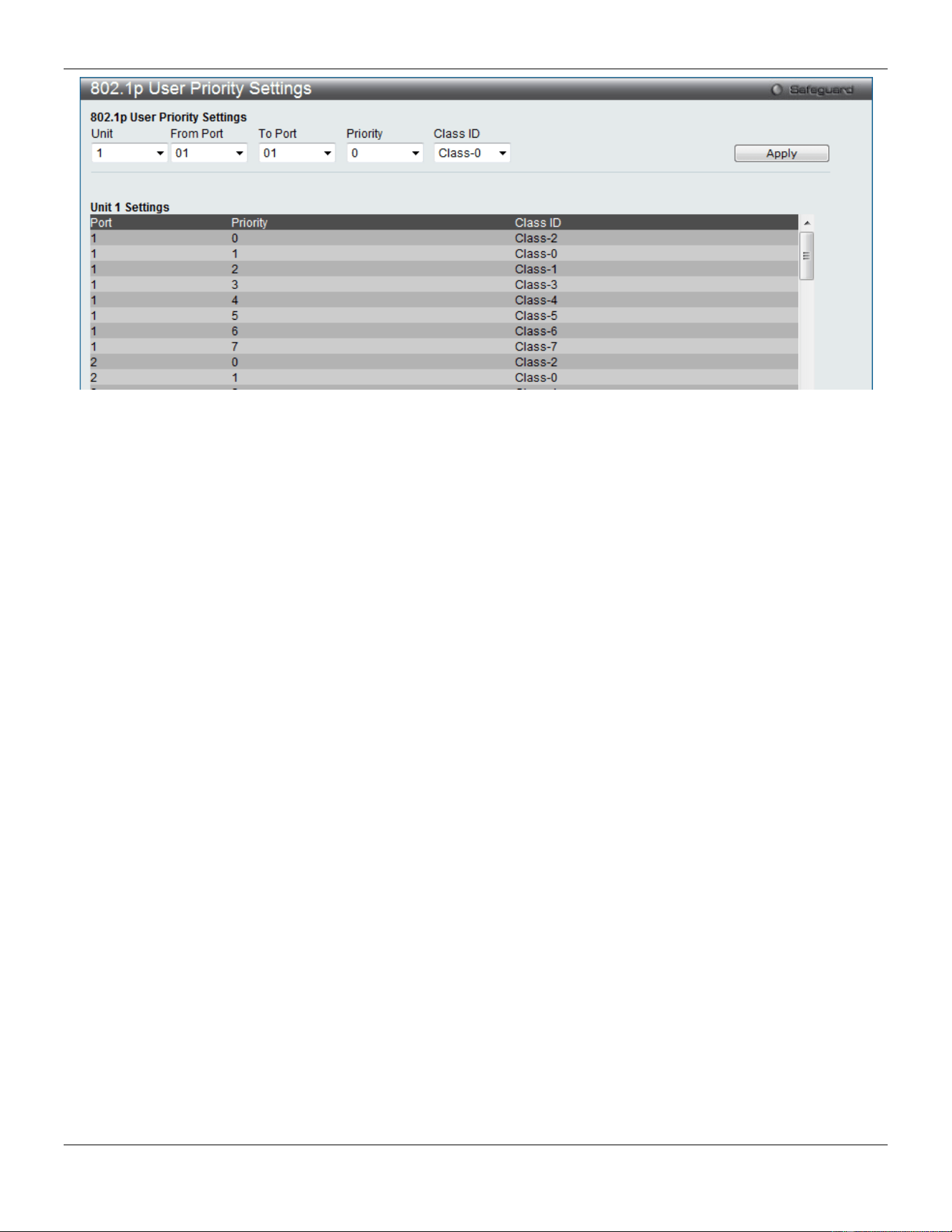
xStack® DGS-3420 Series Layer 2 Managed Stackable Gigabit Switch Web UI Reference Guide
210
Figure 6-3 802.1p User Priority Settings window
Once a priority has been assigned to the port groups on the Switch, then a Class may be assigned to each of the eight
levels of 802.1p priorities using the drop-down menus on this window. User priority mapping is not only for the default
priority configured in the last page, but also for all the incoming tagged packets with 802.1p tag.
Click the Apply button to accept the changes made.
Bandwidth Control
The bandwidth control settings are used to place a ceiling on the transmitting and receiving data rates for any selected
port.
Bandwidth Control Settings
The Effective RX/TX Rate refers to the actual bandwidth of the switch port, if it does not match the configured rate.
This usually means that the bandwidth has been assigned by a higher priority resource, such as a RADIUS server.
To view the following window, click QoS > Bandwidth Control > Bandwidth Control Settings, as show below:
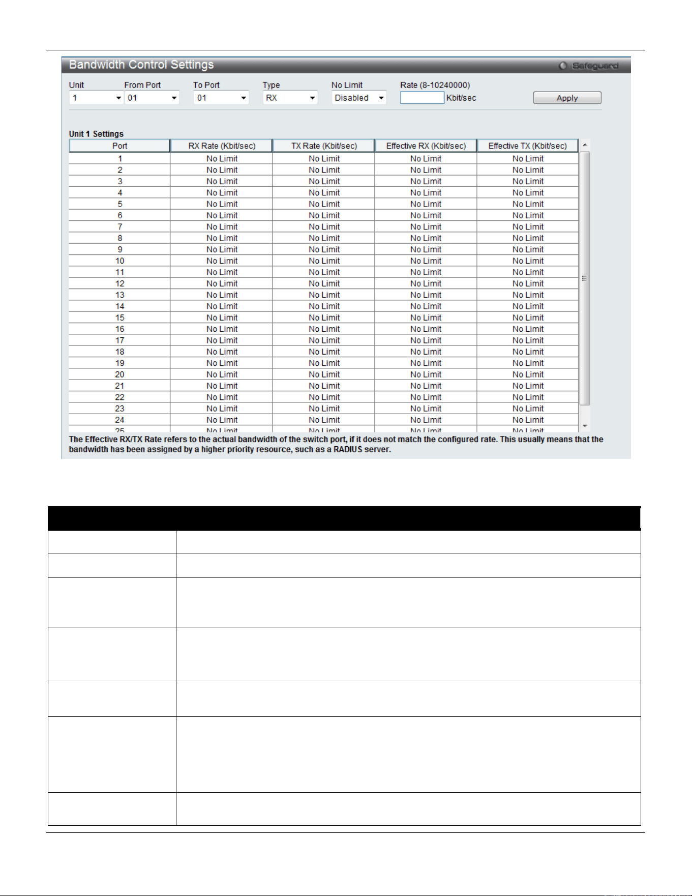
xStack® DGS-3420 Series Layer 2 Managed Stackable Gigabit Switch Web UI Reference Guide
211
Figure 6-4 Bandwidth Control Settings window
The fields that can be configured or displayed are described below:
Parameter Description
Unit
Select the unit you wish to configure.
From Port / To Port
Use the drop-down menu to select the port range to use for this configuration.
Type This drop-down menu allows a selection between RX (receive), TX (transmit), and Both.
This setting will determine whether the bandwidth ceiling is applied to receiving,
transmitting, or both receiving and transmitting packets.
No Limit
This drop-down menu allows the user to specify that the selected port will have no
bandwidth limit or not.
NOTE: If the configured number is larger than the port speed, it means no bandwidth limit.
Rate (8-10240000)
This field allows the input of the data rate that will be the limit for the selected port. The
user may choose a rate between 8 and 10240000 Kbits per second.
Effective RX
If a RADIUS server has assigned the RX bandwidth, then it will be the effective RX
bandwidth. The authentication with the RADIUS sever can be per port or per user. For per
user authentication, there may be multiple RX bandwidths assigned if there are multiple
users attached to this specific port. The final RX bandwidth will be the largest one among
these multiple RX bandwidths.
Effective TX
If a RADIUS server has assigned the TX bandwidth, then it will be the effective TX
bandwidth. The authentication with the RADIUS sever can be per port or per user. For per
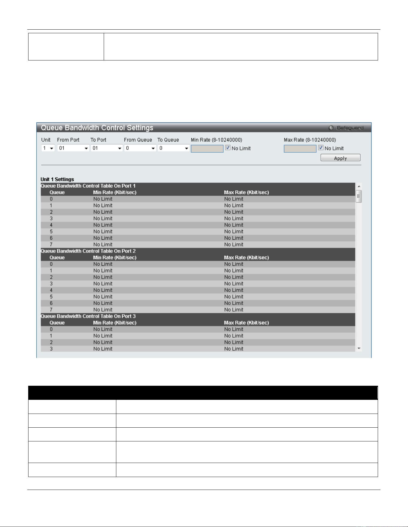
xStack® DGS-3420 Series Layer 2 Managed Stackable Gigabit Switch Web UI Reference Guide
212
user authentication, there may be multiple TX bandwidths assigned if there are multiple
users attached to this specific port. The final TX bandwidth will be the largest one among
these multiple TX bandwidths.
Click the Apply button to accept the changes made.
Queue Bandwidth Control Settings
To view the following window, click QoS > Bandwidth Control > Queue Bandwidth Control Settings, as show below:
Figure 6-5 Queue Bandwidth Control Settings window
The fields that can be configured are described below:
Parameter Description
Unit
Select the unit you wish to configure.
From Port / To Port
Use the drop-down menu to select the port range to use for this configuration.
From Queue / To Queue
Use the drop-down menu to select the queue range to use for this configuration.
Min Rate (8-10240000) Specify the packet limit, in Kbps that the ports are allowed to receive. Tick the No
limit check box to have unlimited rate of packets received by the specified queue.
Max Rate (8-10240000) Enter the maximum rate for the queue. For no limit select the No Limit option.
Click the Apply button to accept the changes made.

xStack® DGS-3420 Series Layer 2 Managed Stackable Gigabit Switch Web UI Reference Guide
213
NOTE: The minimum granularity of queue bandwidth control is 8 Kbit/sec. The system will adjust the
number to the multiple of 8 automatically.
Traffic Control Settings
On a computer network, packets such as Multicast packets and Broadcast packets continually flood the network as
normal procedure. At times, this traffic may increase due to a malicious end station on the network or a malfunctioning
device, such as a faulty network card. Thus, switch throughput problems will arise and consequently affect the overall
performance of the switch network. To help rectify this packet storm, the Switch will monitor and control the situation.
Packet storms are monitored to determine if too many packets are flooding the network based on threshold levels
provided by the user. Once a packet storm has been detected, the Switch will drop packets coming into the Switch until
the storm has subsided. This method can be utilized by selecting the Drop option of the Action parameter in the
window below.
The Switch will also scan and monitor packets coming into the Switch by monitoring the Switch’s chip counter. This
method is only viable for Broadcast and Multicast storms because the chip only has counters for these two types of
packets. Once a storm has been detected (that is, once the packet threshold set below has been exceeded), the
Switch will shut down the port to all incoming traffic, with the exception of STP BPDU packets, for a time period
specified using the Count Down parameter.
If a Time Interval parameter times-out for a port configured for traffic control and a packet storm continues, that port will
be placed in Shutdown Forever mode, which will cause a warning message to be sent to the Trap Receiver. Once in
Shutdown Forever mode, the method of recovering the port is to manually recoup it using the System Configuration >
Port configuration > Port Settings window or automatic recovering after the time period that is configured in the
Traffic Auto Recover Time field. Select the disabled port and return its State to Enabled status. To utilize this method
of Storm Control, choose the Shutdown option of the Action parameter in the window below.
Use this window to enable or disable storm control and adjust the threshold for multicast and broadcast storms.
To view the following window, click QoS > Traffic Control Settings, as show below:
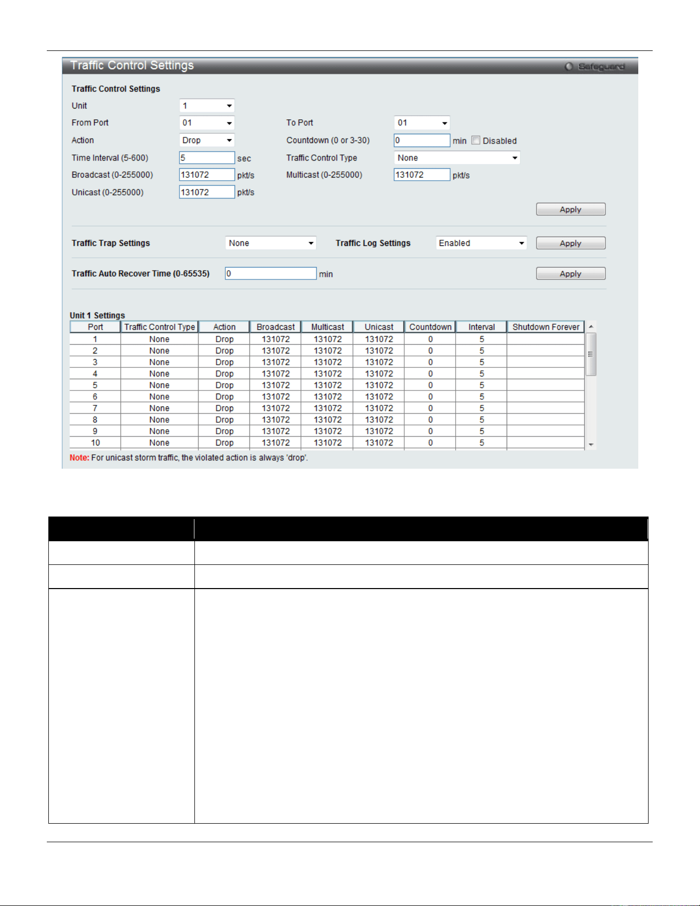
xStack® DGS-3420 Series Layer 2 Managed Stackable Gigabit Switch Web UI Reference Guide
214
Figure 6-6 Traffic Control Settings window
The fields that can be configured are described below:
Parameter Description
Unit
Select the unit you wish to configure.
From Port / To Port
Use the drop-down menu to select the port range to use for this configuration.
Action
Select the method of traffic control from the drop-down menu. The choices are:
Drop – Utilizes the hardware Traffic Control mechanism, which means the Switch’s
hardware will determine the Packet Storm based on the Threshold value stated and
drop packets until the issue is resolved.
Shutdown – Utilizes the Switch’s software Traffic Control mechanism to determine the
Packet Storm occurring. Once detected, the port will deny all incoming traffic to the
port except STP BPDU packets, which are essential in keeping the Spanning Tree
operational on the Switch. If the Count Down timer has expired and yet the Packet
Storm continues, the port will be placed in Shutdown Forever mode and is no longer
operational until the port recovers after 5 minutes automatically or the user manually
resets the port using the Port Settings window (System Configuration > Port
Configuration> Port Settings). Choosing this option obligates the user to configure
the Time Interval setting as well, which will provide packet count samplings from the
Switch’s chip to determine if a Packet Storm is occurring.

xStack® DGS-3420 Series Layer 2 Managed Stackable Gigabit Switch Web UI Reference Guide
215
Countdown (0 or 3-30)
The Count Down timer is set to determine the amount of time, in minutes, that the
Switch will wait before shutting down the port that is experiencing a traffic storm. This
parameter is only useful for ports configured as Shutdown in their Action field and
therefore will not operate for hardware-based Traffic Control implementations. The
possible time settings for this field are 0 and 3 to 30 minutes. Tick the Disabled check
box, and the port will be shut down immediately when detecting storm.
Time Interval (5-600)
The Time Interval will set the time between Multicast and Broadcast packet counts sent
from the Switch’s chip to the Traffic Control function. These packet counts are the
determining factor in deciding when incoming packets exceed the Threshold value.
The Time Interval may be set between 5 and 600 seconds, with a default setting of 5
seconds.
Threshold (0-255000)
Specifies the maximum number of packets per second that will trigger the Traffic
Control function to commence. The configurable threshold range is from 0-255000 with
a default setting of 131072 packets per second.
Traffic Control Type Specifies the desired Storm Control Type: None, Broadcast, Multicast, Unicast,
Broadcast + Multicast, Broadcast + Unicast, Multicast + Unicast, and Broadcast +
Multicast + Unicast.
Broadcast (0-255000)
Enter the number of broadcast packets per second received by the Switch that will
trigger the storm traffic control measure.
Multicast (0-255000)
Enter the number of multicast packets per second received by the Switch that will
trigger the storm traffic control measure.
Unicast (0-255000)
Enter the number of unicast packets per second received by the Switch that will trigger
the storm traffic control measure.
Traffic Trap Settings
Enable sending of Storm Trap messages when the type of action taken by the Traffic
Control function in handling a Traffic Storm is one of the following:
None – Will send no Storm trap warning messages regardless of action taken by the
Traffic Control mechanism.
Storm Occurred – Will send Storm Trap warning messages upon the occurrence of a
Traffic Storm only.
Storm Cleared – Will send Storm Trap messages when a Traffic Storm has been
cleared by the Switch only.
Both – Will send Storm Trap messages when a Traffic Storm has been both detected
and cleared by the Switch.
This function cannot be implemented in the hardware mode. (When Drop is chosen for
the Action parameter)
Traffic Log Settings
Use the drop-down menu to enable or disable the function. If enabled, the traffic
control states are logged when a storm occurs and when a storm is cleared. If the log
state is disabled, the traffic control events are not logged.
Traffic Auto Recover
Time (0-65535)
Enter the time allowed for auto recovery from shutdown for a port. The default value is
0, which means there is no auto recovery and the port remains in shutdown forever
mode. This requires manual entry of the CLI command config ports [ <portlist> | all ]
state enable to return the port to a forwarding state.
Click the Apply button to accept the changes made for each individual section.
NOTE: Traffic Control cannot be implemented on ports that are set for Link Aggregation (Port Trunking).
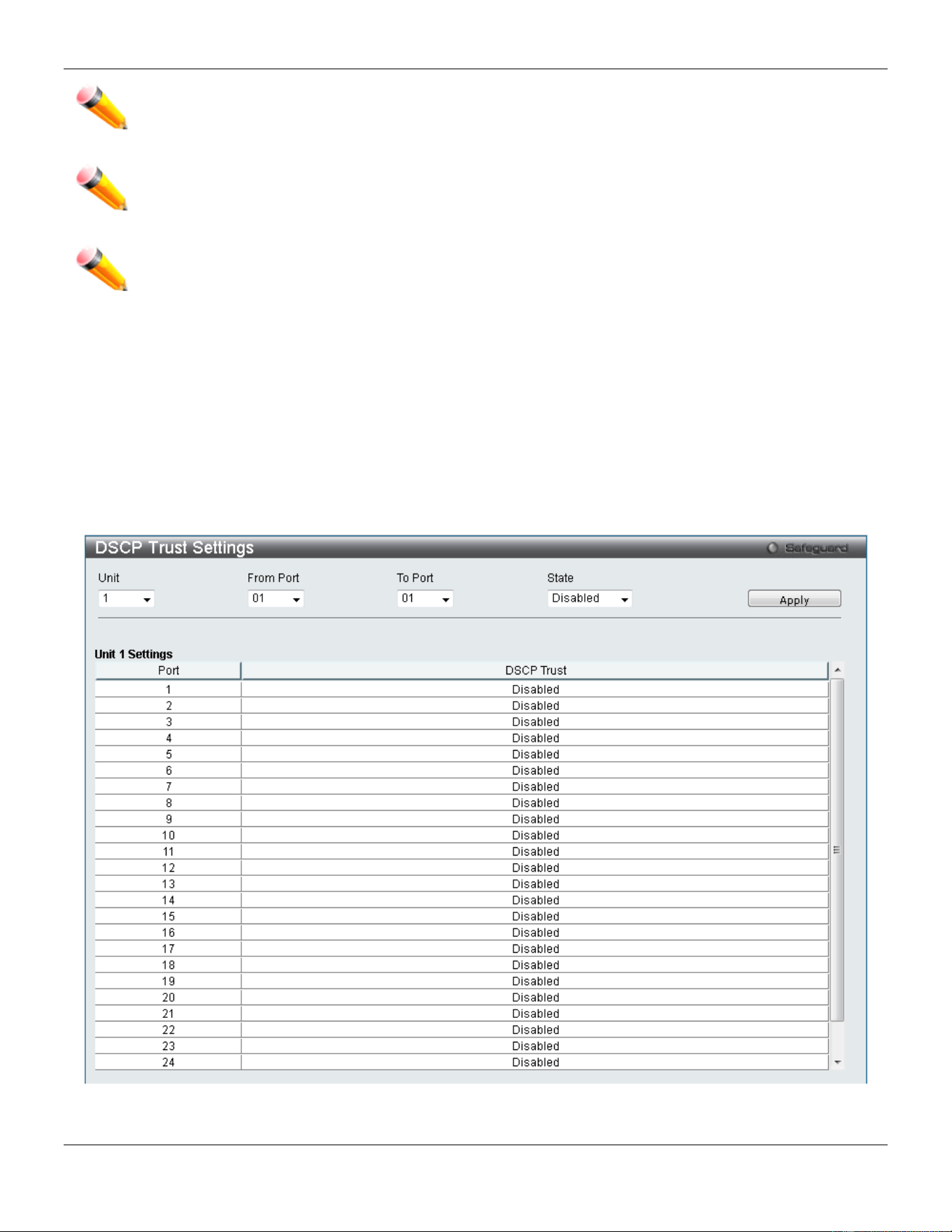
xStack® DGS-3420 Series Layer 2 Managed Stackable Gigabit Switch Web UI Reference Guide
216
NOTE: Ports that are in the Shutdown Forever mode will be seen as Discarding in Spanning Tree
windows and implementations though these ports will still be forwarding BPDUs to the Switch’s
CPU.
NOTE: Ports that are in Shutdown Forever mode will be seen as link down in all windows and screens
until the user recovers these ports.
NOTE: The minimum granularity of storm control on a GE port is 1pps.
DSCP
DSCP Trust Settings
This window is to configure the DSCP trust state of ports. When ports are under the DSCP trust mode, the switch will
insert the priority tag to untagged packets by using the DSCP Map settings instead of the default port priority.
To view the following window, click QoS > DSCP > DSCP Trust Settings, as show below:
Figure 6-7 DSCP Trust Settings window
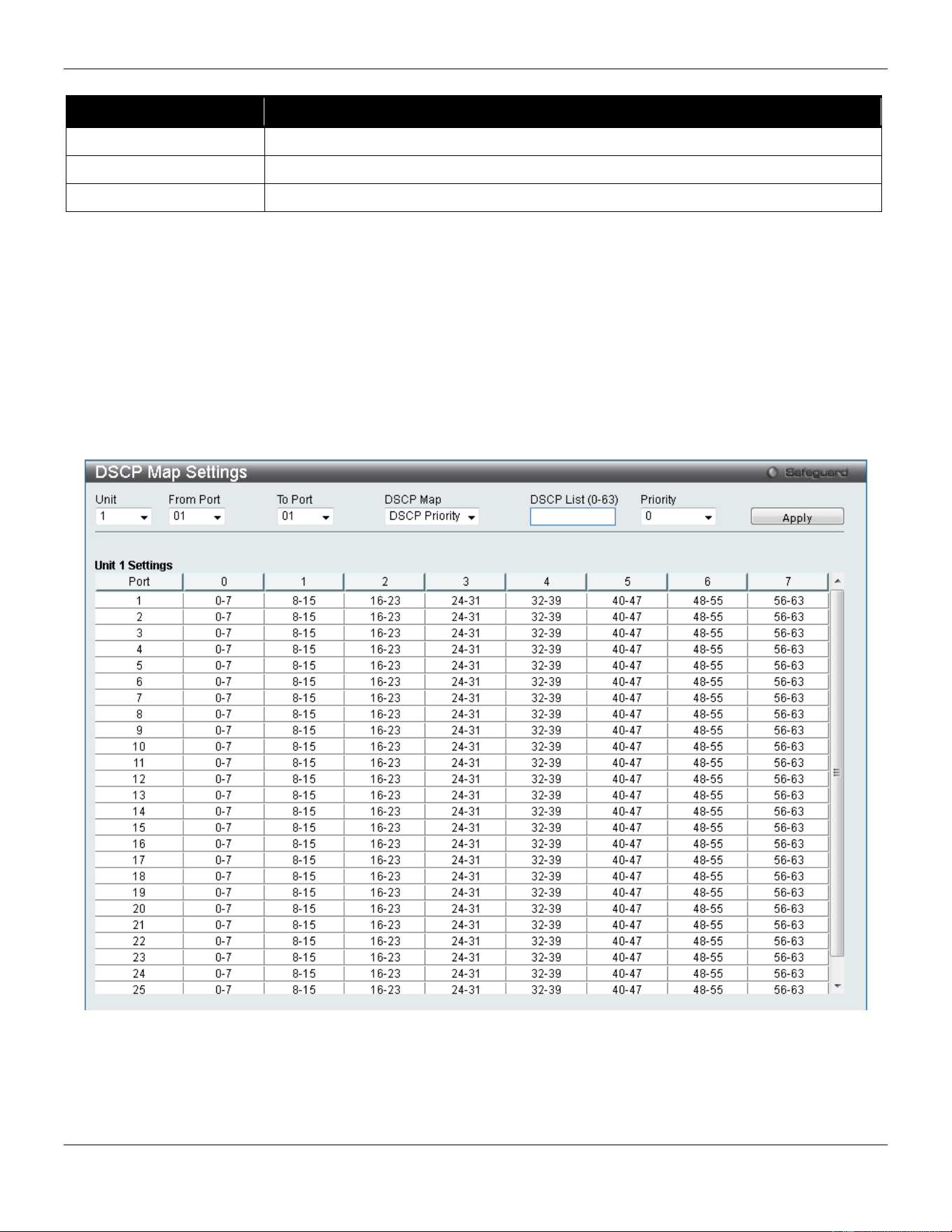
xStack® DGS-3420 Series Layer 2 Managed Stackable Gigabit Switch Web UI Reference Guide
217
The fields that can be configured are described below:
Parameter Description
Unit
Select the unit you want to configure.
From Port / To Port
Use the drop-down menu to select a range of port to configure.
State
Enable/disable to trust DSCP. By default, DSCP trust is disabled.
Click the Apply button to accept the changes made.
DSCP Map Settings
The mapping of DSCP to queue will be used to determine the priority of the packet (which will be then used to
determine the scheduling queue) when the port is in DSCP trust state.
The DSCP-to-DSCP mapping is used in the swap of DSCP of the packet when the packet is ingresses to the port. The
remaining processing of the packet will base on the new DSCP. By default, the DSCP is mapped to the same DSCP.
To view the following window, click QoS > DSCP > DSCP Map Settings, as show below:
Figure 6-8 DSCP Map Settings - DSCP Priority window
To view the following window, click QoS > DSCP > DSCP Map Settings and select DSCP DSCP from the DSCP Map
drop-down menu, as show below:
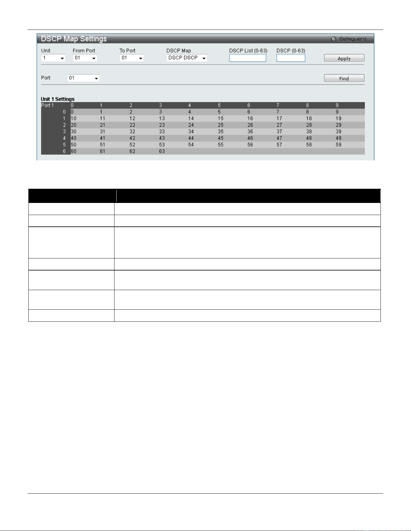
xStack® DGS-3420 Series Layer 2 Managed Stackable Gigabit Switch Web UI Reference Guide
218
Figure 6-9 DSCP Map Settings - DSCP DSCP window
The fields that can be configured are described below:
Parameter Description
Unit
Select the unit you want to configure.
From Port / To Port
Use the drop-down menu to select a range of port to configure.
DSCP Map
Use the drop-down menu to select one of two options:
DSCP Priority – Specify a list of DSCP values to be mapped to a specific priority.
DSCP DSCP – Specify a list of DSCP value to be mapped to a specific DSCP.
DSCP List (0-63)
Enter a DSCP List value.
Priority Use the drop-down menu to select a Priority value. This appears when selecting DSCP
Priority in the DSCP Map drop-down menu.
DSCP (0-63) Enter a DSCP value. This appears when selecting DSCP DSCP in the DSCP Map
drop-down menu.
Port
Use the drop-down menu to select a port.
Click the Apply button to accept the changes made.
Click the Find button to locate a specific entry based on the information entered.
HOL Blocking Prevention
HOL (Head of Line) Blocking happens when one of the destination ports of a broadcast or multicast packet are busy.
The switch will hold this packet in the buffer while the other destination port will not transmit the packet even they are
not busy.
The HOL Blocking Prevention will ignore the busy port and forward the packet directly to have lower latency and better
performance.
On this page the user can enable or disable HOL Blocking Prevention.
To view the following window, click QoS > HOL Blocking Prevention, as show below:
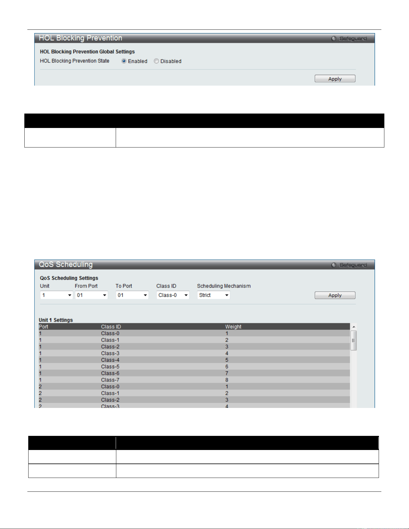
xStack® DGS-3420 Series Layer 2 Managed Stackable Gigabit Switch Web UI Reference Guide
219
Figure 6-10 HOL blocking Prevention window
The fields that can be configured are described below:
Parameter Description
HOL Blocking Prevention
State
Click the radio buttons to enable of disable the HOL blocking prevention global settings.
Click the Apply button to accept the changes made.
Scheduling Settings
QoS Scheduling
This window allows the user to configure the way the Switch will map an incoming packet per port based on its 802.1p
user priority, to one of the eight available hardware priority queues available on the Switch.
To view this window, click QoS > Scheduling Settings > QoS Scheduling as shown below:
Figure 6-11 QoS Scheduling window
The following parameters can be configured:
Parameter Description
Unit
Select the unit you wish to configure.
From Port / To Port
Enter the port or port list you wish to configure.
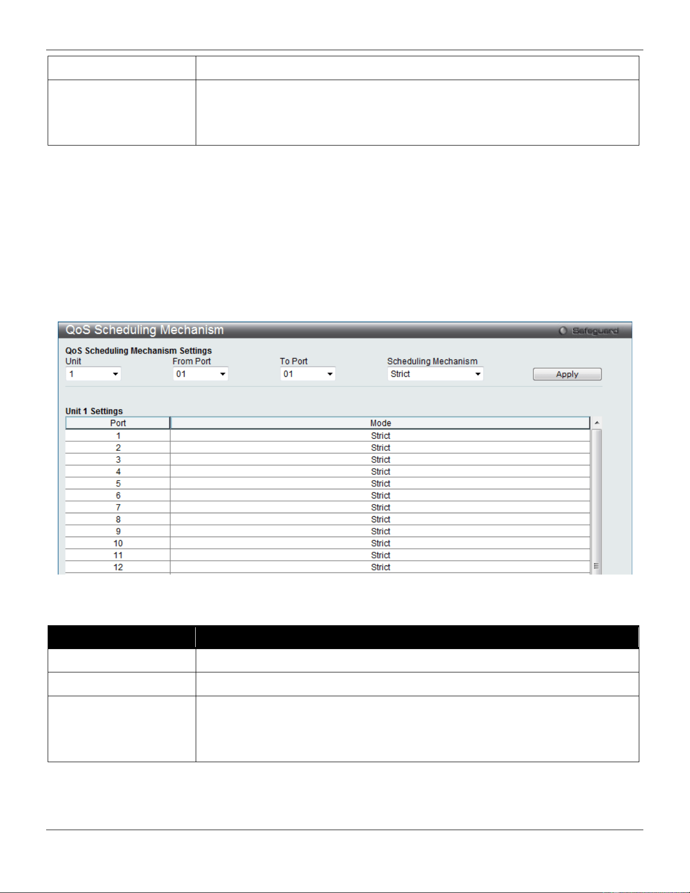
xStack® DGS-3420 Series Layer 2 Managed Stackable Gigabit Switch Web UI Reference Guide
220
Class ID Select the Class ID, from 0-7 to configure for the QoS parameters.
Scheduling Mechanism Strict – The highest class of service is the first to process traffic. That is, the highest
class of service will finish before other queues empty.
Weight – Use the weighted round-robin (WRR) algorithm to handle packets in an even
distribution in priority classes of service.
Click the Apply button to accept the changes made.
QoS Scheduling Mechanism
Changing the output scheduling used for the hardware queues in the Switch can customize QoS. As with any changes
to QoS implementation, careful consideration should be given to how network traffic in lower priority queues are
affected. Changes in scheduling may result in unacceptable levels of packet loss or significant transmission delays. If
you choose to customize this setting, it is important to monitor network performance, especially during peak demand,
as bottlenecks can quickly develop if the QoS settings are not suitable.
To view this window, click QoS > Scheduling Settings > QoS Scheduling Mechanism as shown below:
Figure 6-12 QoS Scheduling Mechanism
The following parameters can be configured:
Parameter Description
Unit
Select the unit you wish to configure.
From Port / To Port
Enter the port or port list you wish to configure.
Scheduling Mechanism Strict – The highest class of service is the first to process traffic. That is, the highest
class of service will finish before other queues empty.
Weighted Round Robin – Use the weighted round-robin algorithm to handle packets in
an even distribution in priority classes of service.
Click the Apply button to accept the changes made.
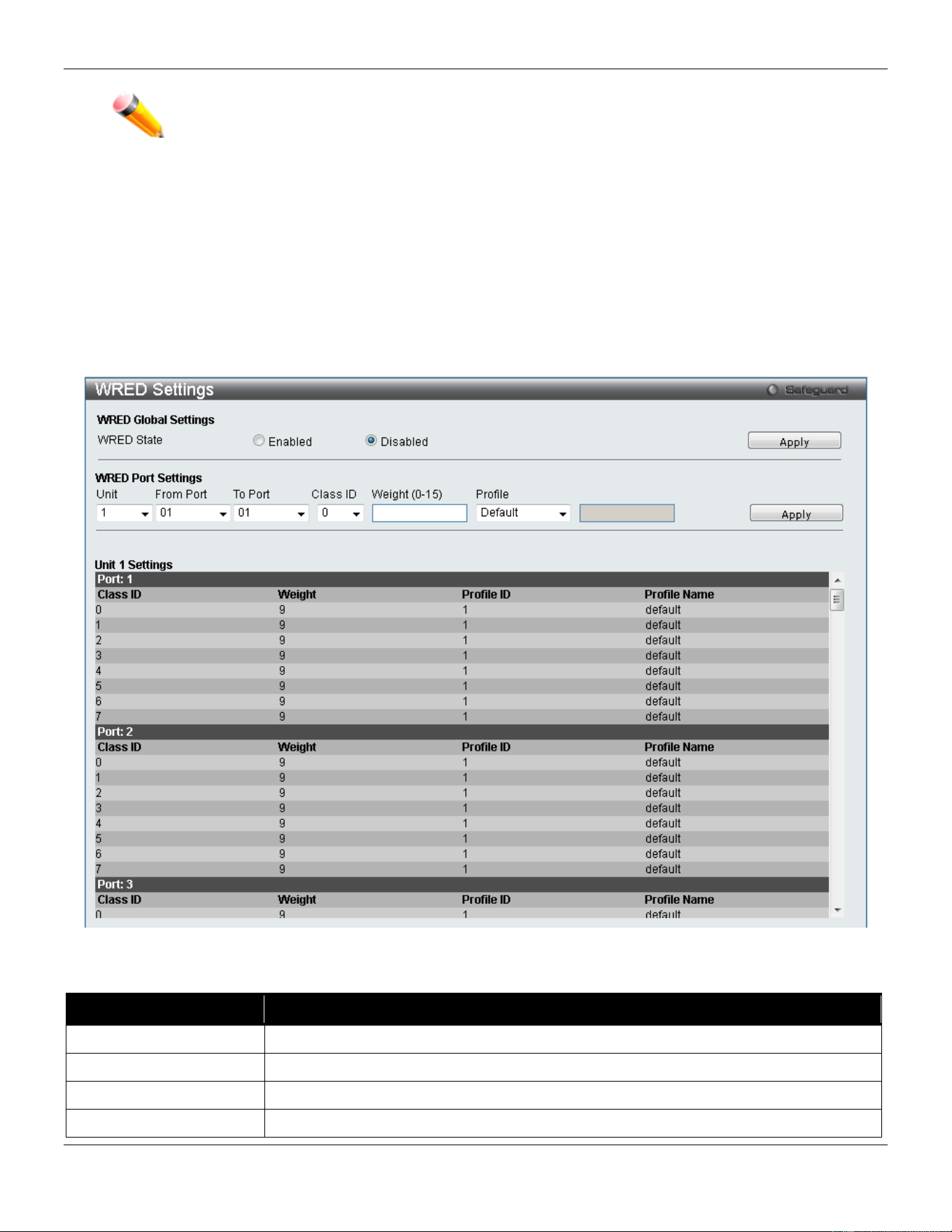
xStack® DGS-3420 Series Layer 2 Managed Stackable Gigabit Switch Web UI Reference Guide
221
NOTE: The settings you assign to the queues, numbers 0-7, represent the IEEE 802.1p priority
tag number. Do not confuse these settings with port numbers.
WRED
WRED Port Settings
This window is used to configure the WRED state and its port settings.
To view the following window, click QoS > WRED > WRED Port Settings, as show below:
Figure 6-13 WRED Settings window
The fields that can be configured are described below:
Parameter Description
WRED State
Click to enable or disable the WRED global state.
Unit
Select the unit you want to configure.
From Port / To Port
Use the drop-down menu to select the port range to use for this configuration.
Class ID
Use the drop-down menu to select the hardware priority.
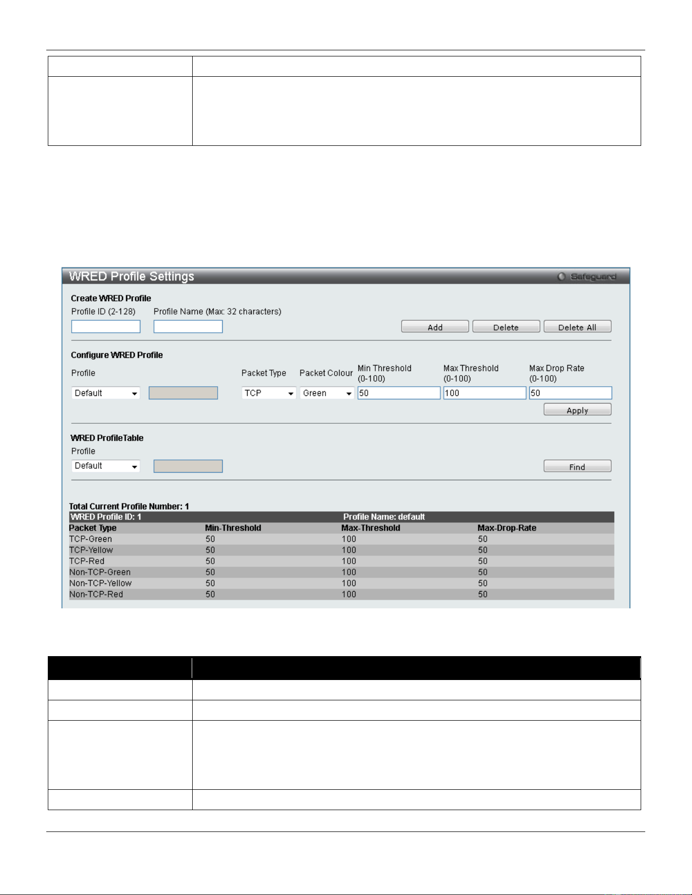
xStack® DGS-3420 Series Layer 2 Managed Stackable Gigabit Switch Web UI Reference Guide
222
Weight (0-15)
Specify the weight in the average queue size calculation.
Profile
Use the drop-down menu to select the profile to be used for WERD ports and queue.
Default – Specify the default profile to be used.
Profile ID – Select and enter a profile ID to be used.
Profile Name – Select and enter a profile name to be used.
Click the Apply button to accept the changes made for each individual section.
WRED Profile Settings
This window is used to configure the WRED profile settings.
To view the following window, click QoS > WRED > WRED Profile Settings, as show below:
Figure 6-14 WRED Profile Settings window
The fields that can be configured are described below:
Parameter Description
Profile ID (2-128)
Enter a WRED profile ID to be added or deleted.
Profile Name
Enter a WRED profile name to be added or deleted.
Profile
Use the drop-down menu to select the profile to be used for WRED ports and queue.
Default – Specify the default profile to be used.
Profile ID – Select and enter a profile ID to be used.
Profile Name – Select and enter a profile name to be used.
Packet Type
Select the packet type, TCP or Non-TCP to be dropped.

xStack® DGS-3420 Series Layer 2 Managed Stackable Gigabit Switch Web UI Reference Guide
223
Packet Colour
Select the packet color, Green, yellow or red, to be dropped.
Min Threshold (0-100)
Enter the minimum threshold value used. If the queue size is higher than this value,
then the color yellow will be assigned to it. If the queue size is lower than this value,
then the color green will be assigned to it and then it will be guaranteed not to be
dropped. Yellow packet behavior depends on the profile setting for this color.
Max Threshold (0-100)
Enter the maximum threshold value used. If the queue size is lower than this value,
then the color yellow will be assigned to it. If the queue size is higher than this value,
then the color red will be assigned to it and then it will be dropped. Yellow packet
behavior depends on the profile setting for this color.
Max Drop Rate (0-100)
Enter the maximum drop rate value.
Click the Add button to add a new entry based on the information entered.
Click the Delete button to remove the entry based on the information entered.
Click the Delete All button to remove all the entries listed.
Click the Apply button to accept the changes made.
Click the Find button to locate a specific entry based on the information entered.
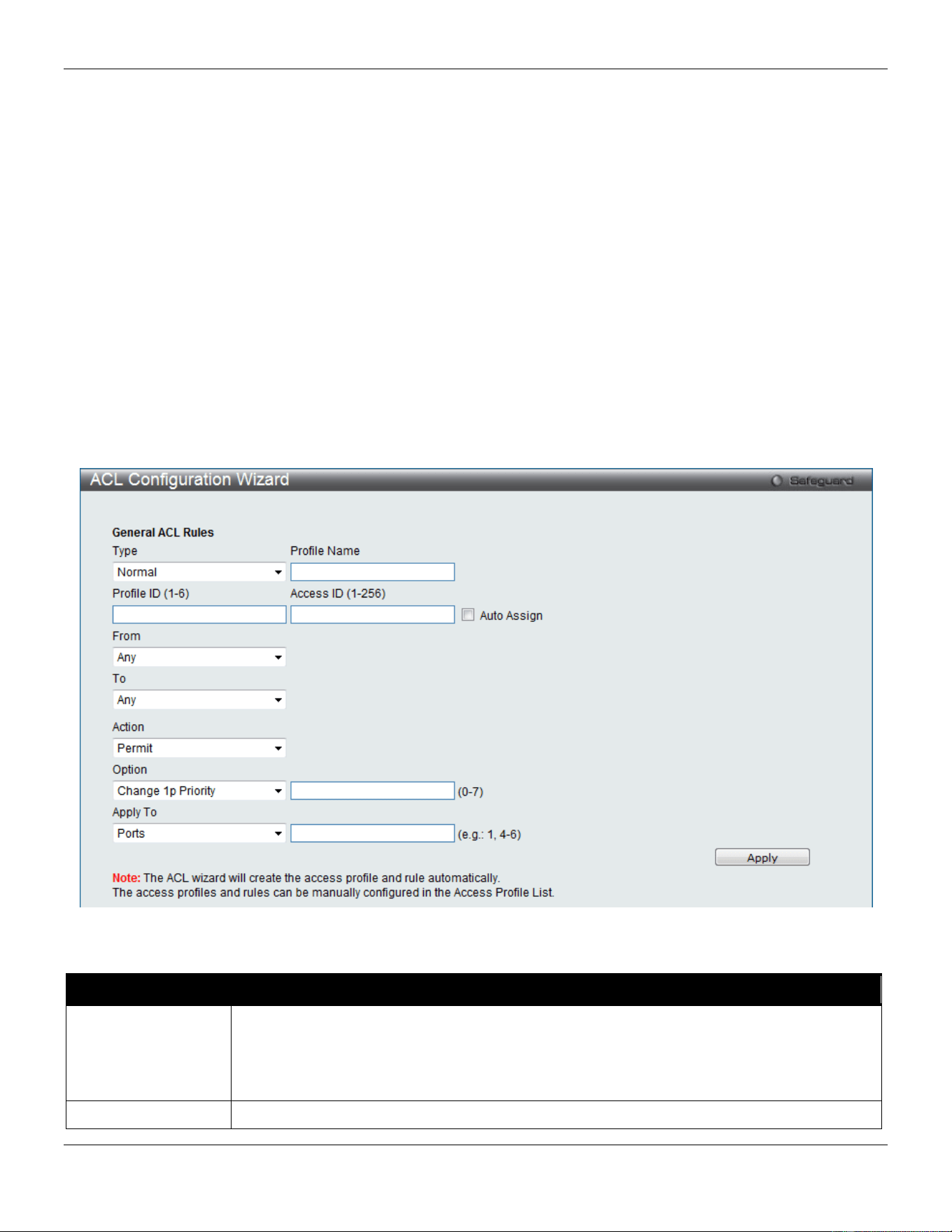
xStack® DGS-3420 Series Layer 2 Managed Stackable Gigabit Switch Web UI Reference Guide
224
Chapter 7 ACL
ACL Configuration Wizard
Access Profile List
CPU Access Profile List
ACL Finder
ACL Flow Meter
Egress Access Profile List
Egress ACL Flow Meter
ACL Configuration Wizard
The ACL Configuration Wizard will aid the user in the creation of access profiles and ACL Rules automatically by
simply inputting the address or service type and the action needed. It saves administrators a lot of time.
To view this window, click ACL > ACL Configuration Wizard as shown below:
Figure 7-1 ACL Configuration Wizard window
The fields that can be configured are described below:
Parameter Description
Type
Use the drop-down menu to select the general ACL Rule types:
Normal – Selecting this option will create a Normal ACL Rule.
CPU – Selecting this option will create a CPU ACL Rule.
Egress - Selecting this option will create an Egress ACL Rule.
Profile Name
After selecting to configure a Normal type rule, the user can enter the Profile Name for the

xStack® DGS-3420 Series Layer 2 Managed Stackable Gigabit Switch Web UI Reference Guide
225
new rule here.
Profile ID
Enter the Profile ID for the new rule.
Access ID Enter the Access ID for the new rule. Selecting the Auto Assign option will allow the switch
to automatically assign an unused access ID to this rule.
From / To
This rule can be created to apply to four different categories:
Any – Selecting this option will include any starting category to this rule.
MAC Address – Selecting this option will allow the user to enter a range of MAC addresses
for this rule.
IPv4 Address – Selecting this option will allow the user to enter a range of IPv4 addresses
for this rule.
IPv6 – Selecting this option will allow the user to enter a range of IPv6 addresses for this
rule.
Action Select Permit to specify that the packets that match the access profile are forwarded by the
Switch, according to any additional rule added (see below).
Select Deny to specify that the packets that match the access profile are not forwarded by
the Switch and will be filtered.
Select Mirror to specify that packets that match the access profile are mirrored to a port
defined in the mirror port section. Port Mirroring must be enabled and a target port must be
set.
Option After selecting the Permit action, the user can select one of the following options:
Change 1p Priority – Here the user can enter the 1p priority value.
Replace DSCP – Here the user can enter the DSCP value.
Replace ToS Precedence – Here the user can enter the ToS Precedence value.
Apply To
Use the drop-down menu to select and enter the information that this rule will be applied to.
Ports – Enter a port number or a port range.
VLAN Name – Enter a VLAN name.
VLAN ID – Enter a VLAN ID.
Click the Apply button to accept the changes made.
NOTE: The Switch will use one minimum mask to cover all the terms that user input, however, some extra
bits may also be masked at the same time. To optimize the ACL profile and rules, please use
manual configuration.
Access Profile List
Access profiles allow you to establish criteria to determine whether the Switch will forward packets based on the
information contained in each packet's header.
To view Access Profile List window, click ACL > Access Profile List as shown below:
The Switch supports four Profile Types, Ethernet ACL, IPv4 ACL, IPv6 ACL, and Packet Content ACL.
Creating an access profile is divided into two basic parts. The first is to specify which part or parts of a frame the Switch
will examine, such as the MAC source address or the IP destination address. The second part is entering the criteria
the Switch will use to determine what to do with the frame. The entire process is described below in two parts.
Users can display the currently configured Access Profiles on the Switch.
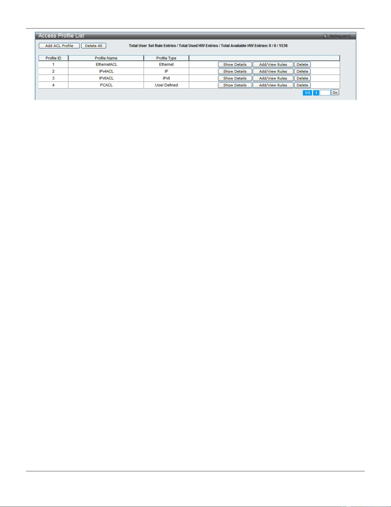
xStack® DGS-3420 Series Layer 2 Managed Stackable Gigabit Switch Web UI Reference Guide
226
Figure 7-2 Access Profile List window
Click the Add ACL Profile button to add an entry to the Access Profile List.
Click the Delete All button to remove all access profiles from this table.
Click the Show Details button to display the information of the specific profile ID entry.
Click the Add/View Rules button to view or add ACL rules within the specified profile ID.
Click the Delete button to remove the specific entry.
Enter a page number and click the Go button to navigate to a specific page when multiple pages exist.
There are four Add Access Profile windows;
• one for Ethernet (or MAC address-based) profile configuration,
• one for IPv6 address-based profile configuration,
• one for IPv4 address-based profile configuration, and
• one for packet content profile configuration.
Adding an Ethernet ACL Profile
The window shown below is the Add ACL Profile window for Ethernet. To use specific filtering masks in this ACL profile,
click the packet filtering mask field to highlight it red. This will add more filed to the mask.
After clicking the Add ACL Profile button, the following page will appear:
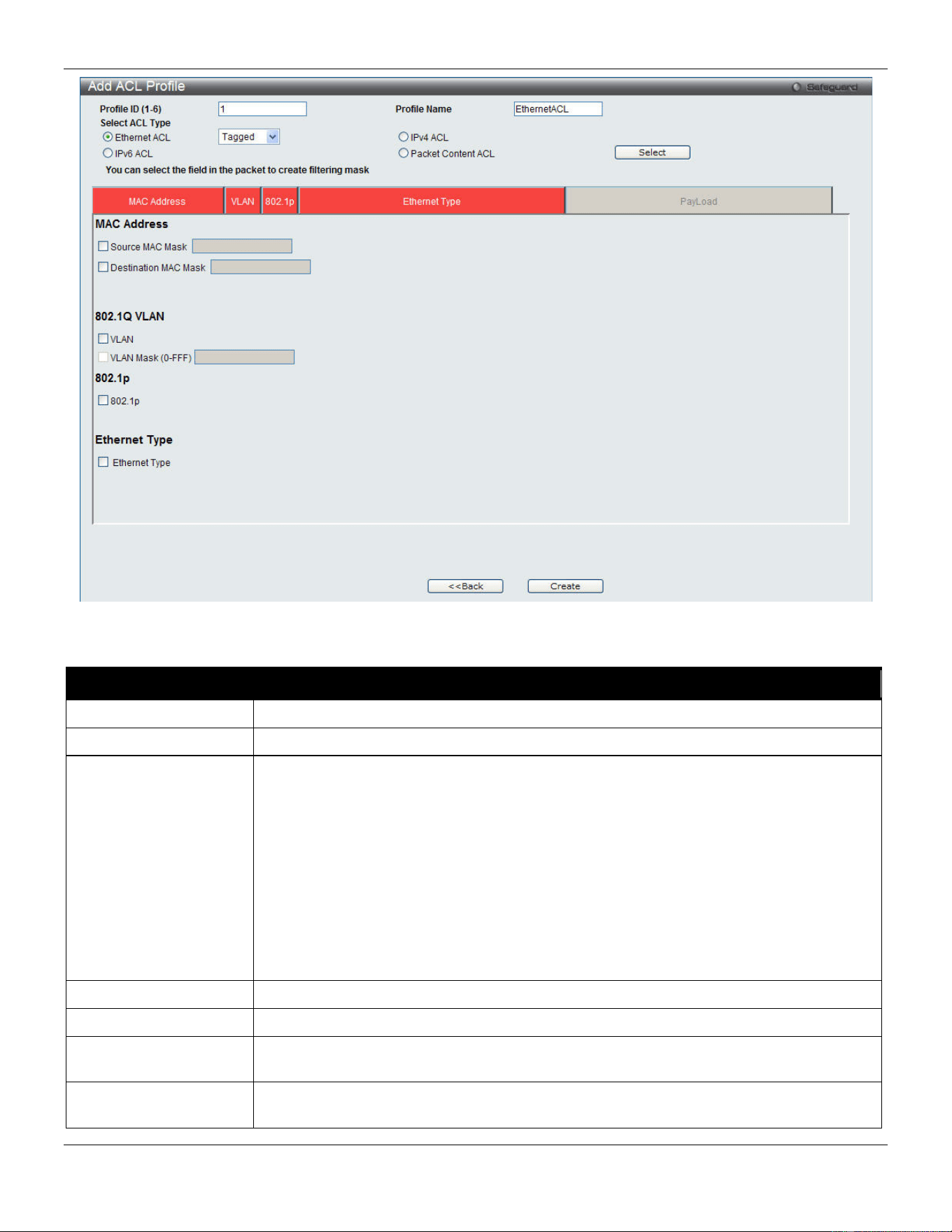
xStack® DGS-3420 Series Layer 2 Managed Stackable Gigabit Switch Web UI Reference Guide
227
Figure 7-3 Add ACL Profile window (Ethernet ACL)
The fields that can be configured are described below:
Parameter Description
Profile ID (1-6)
Enter a unique identifier number for this profile set. This value can be set from 1 to 6.
Profile Name
Enter a profile name for the profile created.
Select ACL Type
Select profile based on Ethernet (MAC Address), IPv4 address, IPv6 address, or packet
content. This will change the window according to the requirements for the type of
profile.
Select Ethernet ACL to instruct the Switch to examine the layer 2 part of each packet
header.
Select IPv4 ACL to instruct the Switch to examine the IPv4 address in each frame's
header.
Select IPv6 ACL to instruct the Switch to examine the IPv6 address in each frame's
header.
Select Packet Content to instruct the Switch to examine the packet content in each
frame’s header.
Source MAC Mask
Enter a MAC address mask for the source MAC address, e.g. FF-FF-FF-FF-FF-FF.
Destination MAC Mask
Enter a MAC address mask for the destination MAC address, e.g. FF-FF-FF-FF-FF-FF.
802.1Q VLAN
Selecting this option instructs the Switch to examine the 802.1Q VLAN identifier of each
packet header and use this as the full or partial criterion for forwarding.
802.1p
Selecting this option instructs the Switch to examine the 802.1p priority value of each
packet header and use this as the, or part of the criterion for forwarding.
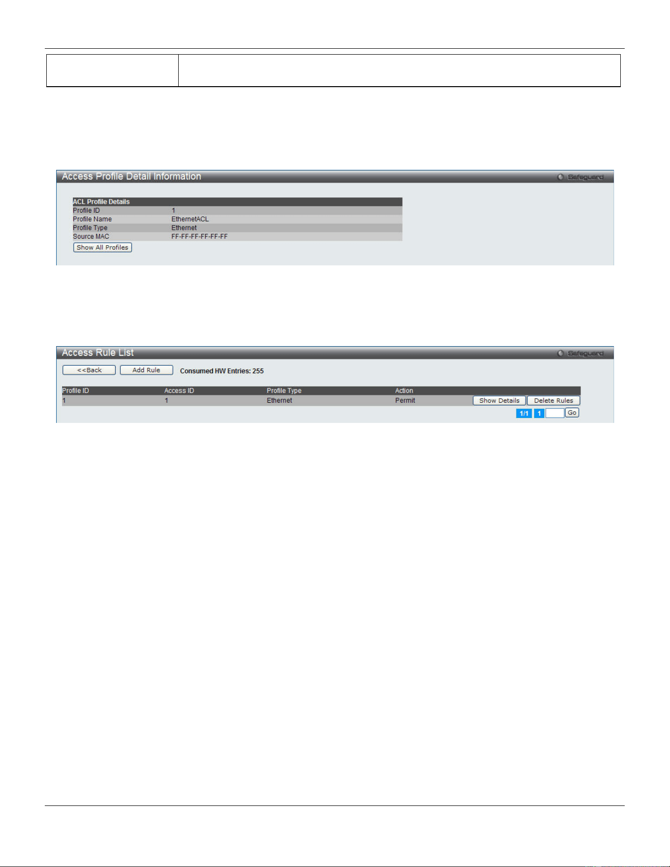
xStack® DGS-3420 Series Layer 2 Managed Stackable Gigabit Switch Web UI Reference Guide
228
Ethernet Type
Selecting this option instructs the Switch to examine the Ethernet type value in each
frame's header.
Click the Select button to select an ACL type.
Click the <<Back button to discard the changes made and return to the previous page.
Click the Create button to create a profile.
After clicking the Show Details button, the following page will appear:
Figure 7-4 Access Profile Detail Information window (Ethernet ACL)
Click the Show All Profiles button to navigate back to the Access Profile List window.
After clicking the Add/View Rules button, the following page will appear:
Figure 7-5 Access Rule List window (Ethernet ACL)
Click the <<Back button to return to the previous page.
Click the Add Rule button to create a new ACL rule in this profile.
Click the Show Details button to view more information about the specific rule created.
Click the Delete Rules button to remove the specific entry.
Enter a page number and click the Go button to navigate to a specific page when multiple pages exist.
After clicking the Add Rule button, the following page will appear:
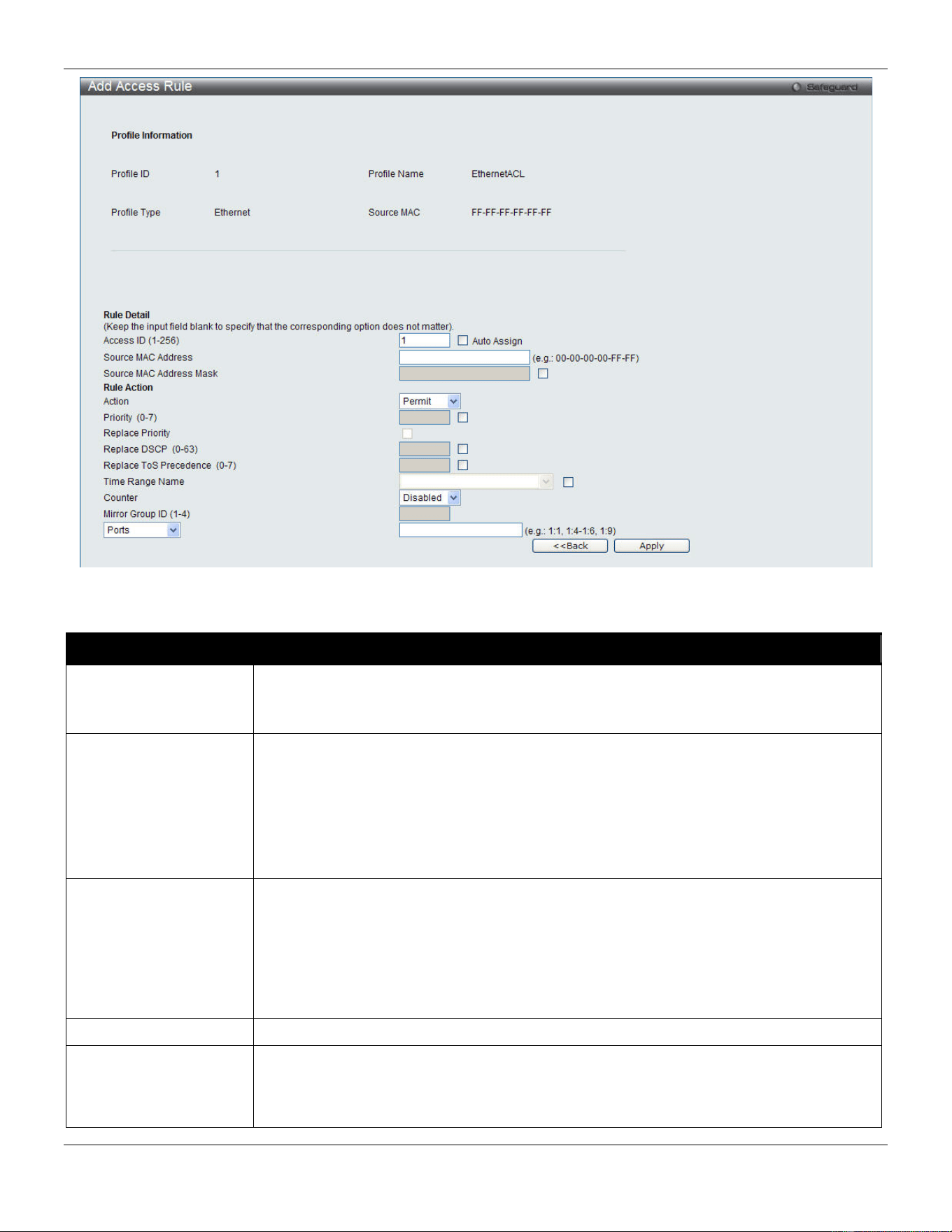
xStack® DGS-3420 Series Layer 2 Managed Stackable Gigabit Switch Web UI Reference Guide
229
Figure 7-6 Add Access Rule window (Ethernet ACL)
The fields that can be configured are described below:
Parameter Description
Access ID (1-256)
Type in a unique identifier number for this access. This value can be set from 1 to 256.
Auto Assign – Tick the check box will instruct the Switch to automatically assign an
Access ID for the rule being created.
Action Select Permit to specify that the packets that match the access profile are forwarded by
the Switch, according to any additional rule added (see below).
Select Deny to specify that the packets that match the access profile are not forwarded
by the Switch and will be filtered.
Select Mirror to specify that packets that match the access profile are mirrored to a port
defined in the config mirror port command. Port Mirroring must be enabled and a target
port must be set.
Priority (0-7)
Tick the corresponding check box if you want to re-write the 802.1p default priority of a
packet to the value entered in the Priority field, which meets the criteria specified
previously in this command, before forwarding it on to the specified CoS queue.
Otherwise, a packet will have its incoming 802.1p user priority re-written to its original
value before being forwarded by the Switch.
For more information on priority queues, CoS queues and mapping for 802.1p, see the
QoS section of this manual.
Replace Priority
Tick this check box to replace the Priority value in the adjacent field.
Replace DSCP (0-63)
Select this option to instruct the Switch to replace the DSCP value (in a packet that
meets the selected criteria) with the value entered in the adjacent field. When an ACL
rule is added to change both the priority and DSCP of an IPv4 packet, only one of them
can be modified due to a chip limitation. Currently the priority is changed when both the
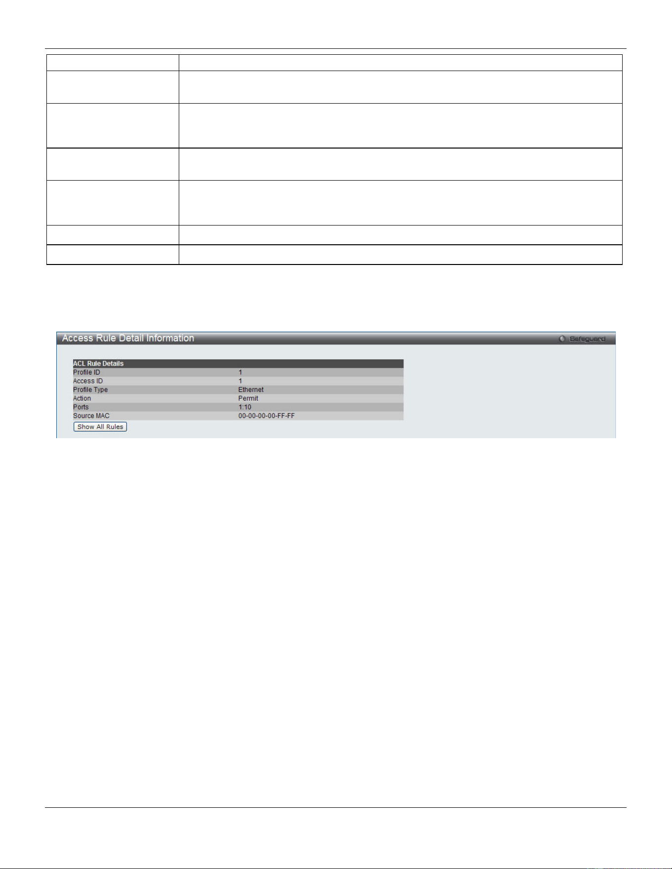
xStack® DGS-3420 Series Layer 2 Managed Stackable Gigabit Switch Web UI Reference Guide
230
priority and DSCP are set to be modified.
Replace ToS
Precedence (0-7)
Specify that the IP precedence of the outgoing packet is changed with the new value. If
used without an action priority, the packet is sent to the default traffic class.
Time Range Name
Tick the check box and enter the name of the Time Range settings that has been
previously configured in the Time Range Settings window. This will set specific times
when this access rule will be implemented on the Switch.
Counter
Here the user can select the counter. By checking the counter, the administrator can see
how many times that the rule was hit.
Ports
When a range of ports is to be configured, the Auto Assign check box MUST be ticked in
the Access ID field of this window. If not, the user will be presented with an error
message and the access rule will not be configured.
VLAN Name
Specify the VLAN name to apply to the access rule.
VLAN ID
Specify the VLAN ID to apply to the access rule.
Click the <<Back button to discard the changes made and return to the previous page.
Click the Apply button to accept the changes made.
After clicking the Show Details button in the Access Rule List, the following page will appear:
Figure 7-7 Access Rule Detail Information window (Ethernet ACL)
Click the Show All Rules button to navigate back to the Access Rule List.
Adding an IPv4 ACL Profile
The window shown below is the Add ACL Profile window for IPv4. To use specific filtering masks in this ACL profile,
click the packet filtering mask field to highlight it red. This will add more filed to the mask.
After clicking the Add ACL Profile button, the following page will appear:
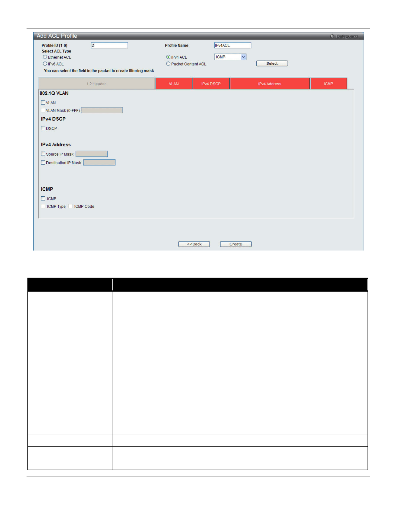
xStack® DGS-3420 Series Layer 2 Managed Stackable Gigabit Switch Web UI Reference Guide
231
Figure 7-8 Add ACL Profile window (IPv4 ACL)
The fields that can be configured are described below:
Parameter Description
Profile ID (1-6)
Enter a unique identifier number for this profile set. This value can be set from 1 to 6.
Select ACL Type
Select profile based on Ethernet (MAC Address), IPv4 address, IPv6 address, or
packet content. This will change the window according to the requirements for the
type of profile.
Select Ethernet ACL to instruct the Switch to examine the layer 2 part of each packet
header.
Select IPv4 ACL to instruct the Switch to examine the IPv4 address in each frame's
header.
Select IPv6 ACL to instruct the Switch to examine the IPv6 address in each frame's
header.
Select Packet Content to instruct the Switch to examine the packet content in each
frame’s header.
802.1Q VLAN
Selecting this option instructs the Switch to examine the 802.1Q VLAN identifier of
each packet header and use this as the full or partial criterion for forwarding.
IPv4 DSCP
Selecting this option instructs the Switch to examine the DiffServ Code part of each
packet header and use this as the, or part of the criterion for forwarding.
IPv4 Source IP Mask
Enter an IP address mask for the source IP address, e.g. 255.255.255.255.
IPv4 Destination IP Mask
Enter an IP address mask for the destination IP address, e.g. 255.255.255.255.
Protocol
Selecting this option instructs the Switch to examine the protocol type value in each
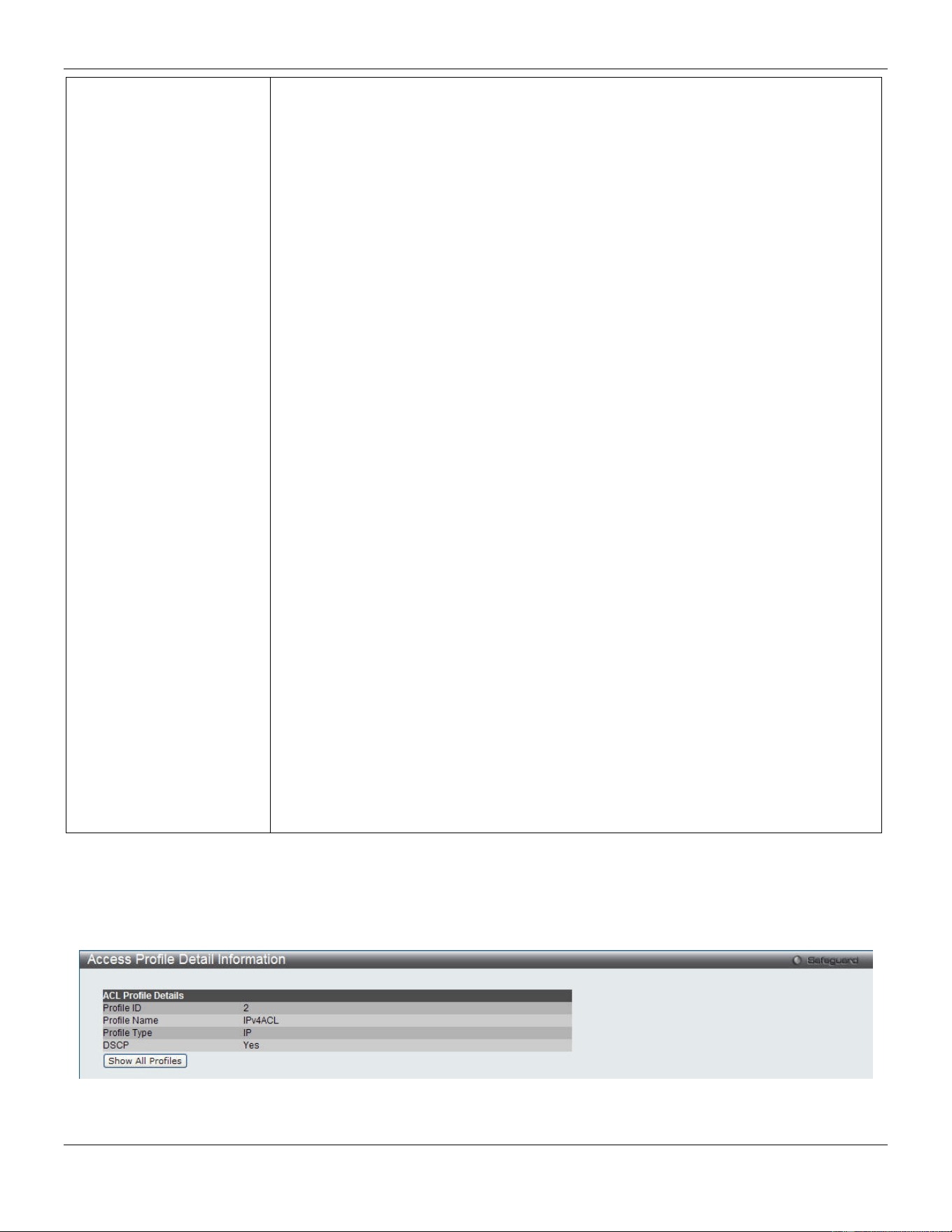
xStack® DGS-3420 Series Layer 2 Managed Stackable Gigabit Switch Web UI Reference Guide
232
frame's header. Then the user must specify what protocol(s) to include according to
the following guidelines:
Select ICMP to instruct the Switch to examine the Internet Control Message Protocol
(ICMP) field in each frame's header.
Select Type to further specify that the access profile will apply an ICMP type value, or
specify Code to further specify that the access profile will apply an ICMP code value.
Select IGMP to instruct the Switch to examine the Internet Group Management
Protocol (IGMP) field in each frame's header.
Select Type to further specify that the access profile will apply an IGMP type value.
Select TCP to use the TCP port number contained in an incoming packet as the
forwarding criterion. Selecting TCP requires that you specify a source port mask
and/or a destination port mask.
src port mask - Specify a TCP port mask for the source port in hex form (hex 0x0-
0xffff), which you wish to filter.
dst port mask - Specify a TCP port mask for the destination port in hex form (hex 0x0-
0xffff) which you wish to filter.
flag bit - The user may also identify which flag bits to filter. Flag bits are parts of a
packet that determine what to do with the packet. The user may filter packets by
filtering certain flag bits within the packets, by checking the boxes corresponding to
the flag bits of the TCP field. The user may choose between urg (urgent), ack
(acknowledgement), psh (push), rst (reset), syn (synchronize), fin (finish).
Select UDP to use the UDP port number contained in an incoming packet as the
forwarding criterion. Selecting UDP requires that you specify a source port mask
and/or a destination port mask.
src port mask - Specify a UDP port mask for the source port in hex form (hex 0x0-
0xffff).
dst port mask - Specify a UDP port mask for the destination port in hex form (hex 0x0-
0xffff).
Select Protocol ID - Enter a value defining the protocol ID in the packet header to
mask. Specify the protocol ID mask in hex form (hex 0x0-0xff.
Protocol ID Mask - Specify that the rule applies to the IP protocol ID traffic.
User Define - Specify the Layer 4 part mask
Click the Select button to select an ACL type.
Click the <<Back button to discard the changes made and return to the previous page.
Click the Create button to create a profile.
After clicking the Show Details button, the following page will appear:
Figure 7-9 Access Profile Detail Information window (IPv4 ACL)
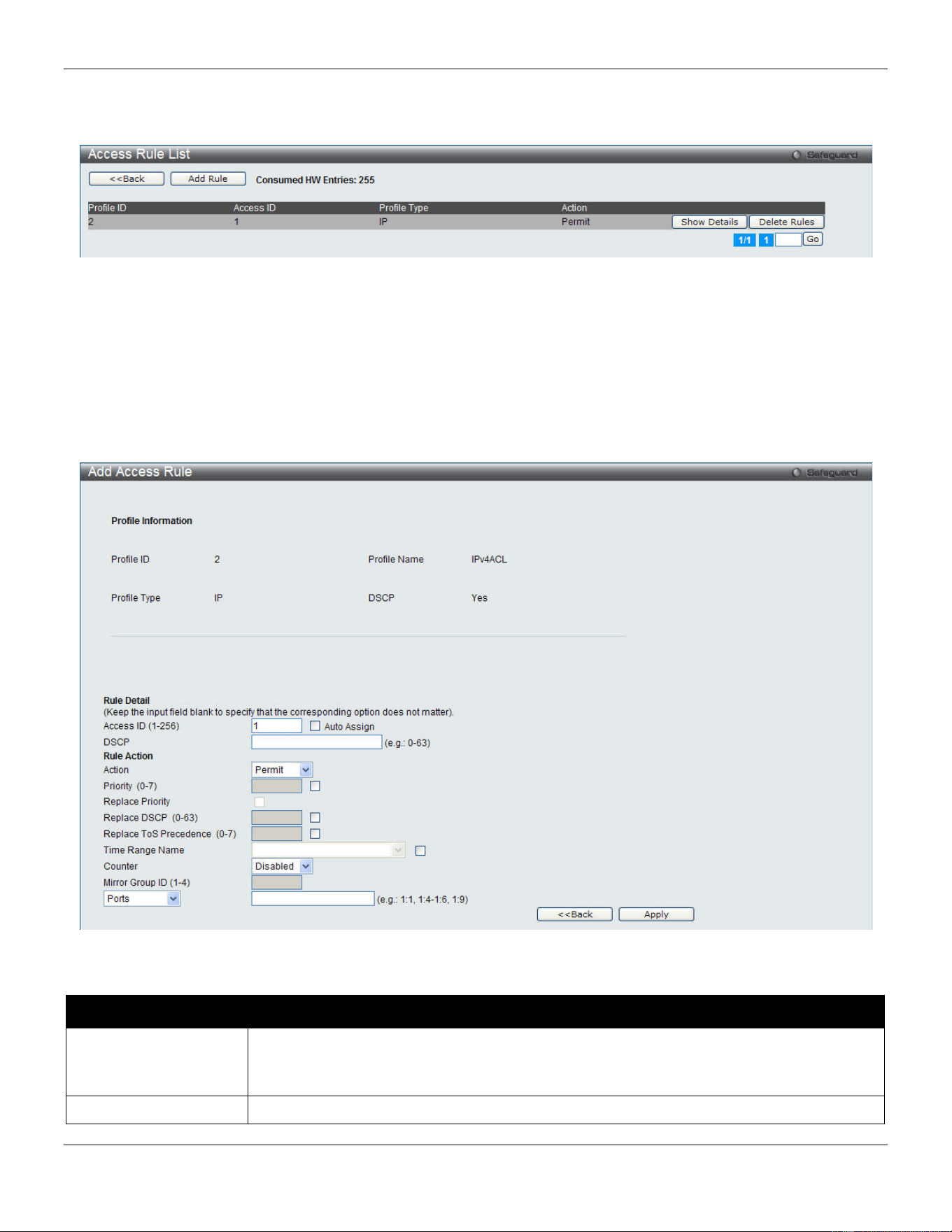
xStack® DGS-3420 Series Layer 2 Managed Stackable Gigabit Switch Web UI Reference Guide
233
Click the Show All Profiles button to navigate back to the Access Profile List window.
After clicking the Add/View Rules button, the following page will appear:
Figure 7-10 Access Rule List window (IPv4 ACL)
Click the <<Back button to return to the previous page.
Click the Add Rule button to create a new ACL rule in this profile.
Click the Show Details button to view more information about the specific rule created.
Click the Delete Rules button to remove the specific entry.
Enter a page number and click the Go button to navigate to a specific page when multiple pages exist.
After clicking the Add Rule button, the following page will appear:
Figure 7-11 Add Access Rule (IPv4 ACL)
The fields that can be configured are described below:
Parameter Description
Access ID (1-256)
Type in a unique identifier number for this access. This value can be set from 1 to 256.
Auto Assign – Tick the check box will instruct the Switch to automatically assign an
Access ID for the rule being created.
Action
Select Permit to specify that the packets that match the access profile are forwarded by
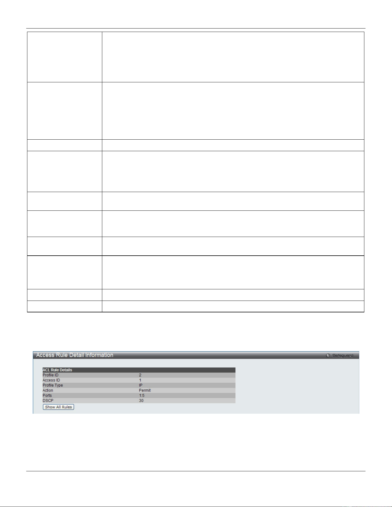
xStack® DGS-3420 Series Layer 2 Managed Stackable Gigabit Switch Web UI Reference Guide
234
the Switch, according to any additional rule added (see below).
Select Deny to specify that the packets that match the access profile are not forwarded by
the Switch and will be filtered.
Select Mirror to specify that packets that match the access profile are mirrored to a port
defined in the config mirror port command. Port Mirroring must be enabled and a target
port must be set.
Priority (0-7)
Tick the corresponding check box if you want to re-write the 802.1p default priority of a
packet to the value entered in the Priority field, which meets the criteria specified
previously in this command, before forwarding it on to the specified CoS queue.
Otherwise, a packet will have its incoming 802.1p user priority re-written to its original
value before being forwarded by the Switch.
For more information on priority queues, CoS queues and mapping for 802.1p, see the
QoS section of this manual.
Replace Priority
Tick this check box to replace the Priority value in the adjacent field.
Replace DSCP (0-63)
Select this option to instruct the Switch to replace the DSCP value (in a packet that meets
the selected criteria) with the value entered in the adjacent field. When an ACL rule is
added to change both the priority and DSCP of an IPv4 packet, only one of them can be
modified due to a chip limitation. Currently the priority is changed when both the priority
and DSCP are set to be modified.
Replace ToS
Precedence (0-7)
Specify that the IP precedence of the outgoing packet is changed with the new value. If
used without an action priority, the packet is sent to the default TC.
Time Range Name
Tick the check box and enter the name of the Time Range settings that has been
previously configured in the Time Range Settings window. This will set specific times
when this access rule will be implemented on the Switch.
Counter
Here the user can select the counter. By checking the counter, the administrator can see
how many times that the rule was hit.
Ports
When a range of ports is to be configured, the Auto Assign check box MUST be ticked in
the Access ID field of this window. If not, the user will be presented with an error message
and the access rule will not be configured. Ticking the All Ports check box will denote all
ports on the Switch.
VLAN Name
Specify the VLAN name to apply to the access rule.
VLAN ID
Specify the VLAN ID to apply to the access rule.
Click the <<Back button to discard the changes made and return to the previous page.
Click the Apply button to accept the changes made.
After clicking the Show Details button in the Access Rule List, the following page will appear:
Figure 7-12 Access Rule Detail Information (IPv4 ACL)
Click the Show All Rules button to navigate back to the Access Rule List.
Adding an IPv6 ACL Profile
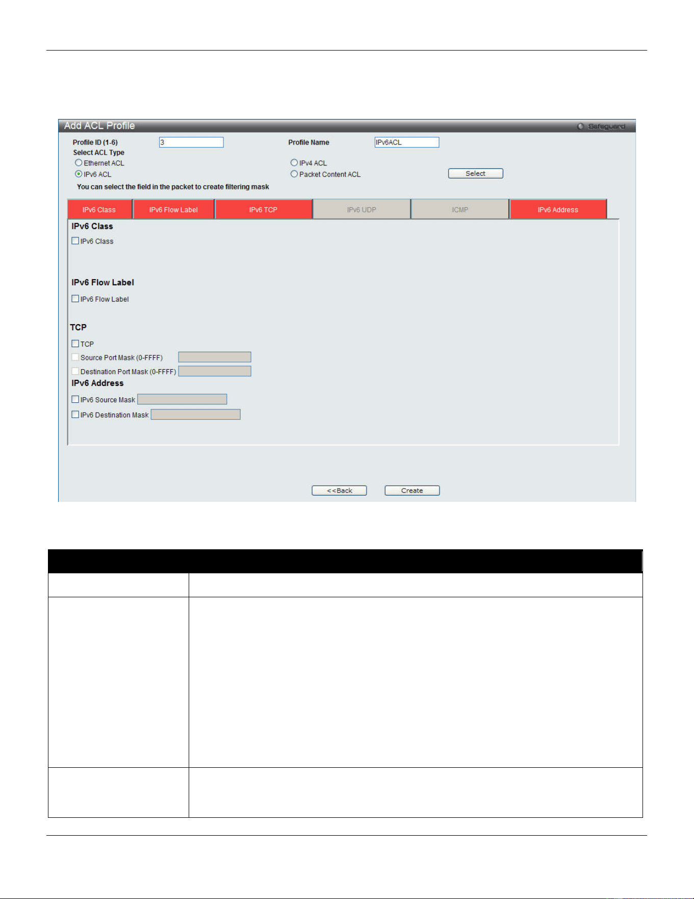
xStack® DGS-3420 Series Layer 2 Managed Stackable Gigabit Switch Web UI Reference Guide
235
The window shown below is the Add ACL Profile window for IPv6. To use specific filtering masks in this ACL profile,
click the packet filtering mask field to highlight it red. This will add more filed to the mask.
After clicking the Add ACL Profile button, the following page will appear:
Figure 7-13 Add ACL Profile window (IPv6 ACL)
The fields that can be configured are described below:
Parameter Description
Profile ID (1-6) Enter a unique identifier number for this profile set. This value can be set from 1 to 6.
Select ACL Type
Select profile based on Ethernet (MAC Address), IPv4 address, IPv6 address, or packet
content. This will change the window according to the requirements for the type of
profile.
• Select Ethernet ACL to instruct the Switch to examine the layer 2 part of each
packet header.
• Select IPv4 ACL to instruct the Switch to examine the IPv4 address in each
frame's header.
• Select IPv6 ACL to instruct the Switch to examine the IPv6 address in each
frame's header.
• Select Packet Content to instruct the Switch to examine the packet content in
each frame’s header.
IPv6 Class Ticking this check box will instruct the Switch to examine the class field of the IPv6
header. This class field is a part of the packet header that is similar to the Type of
Service (ToS) or Precedence bits field in IPv4.
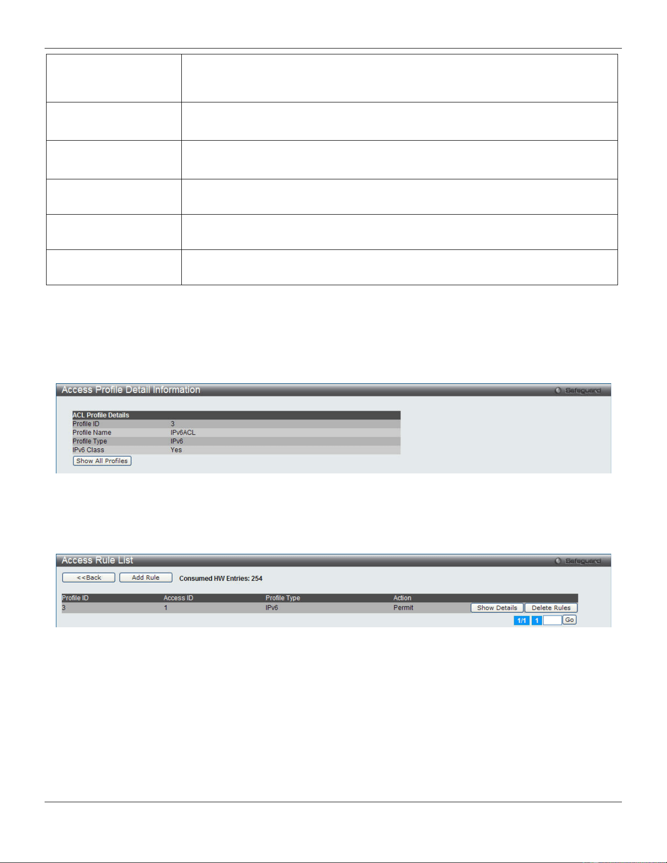
xStack® DGS-3420 Series Layer 2 Managed Stackable Gigabit Switch Web UI Reference Guide
236
IPv6 Flow Label Ticking this check box will instruct the Switch to examine the flow label field of the IPv6
header. This flow label field is used by a source to label sequences of packets such as
non-default quality of service or real time service packets.
IPv6 TCP Source Port Mask – Specify that the rule applies to the range of TCP source ports.
Destination Port Mask – Specify the range of the TCP destination port range.
IPv6 UDP Source Port Mask – Specify the range of the TCP source port range.
Destination Port Mask – Specify the range of the TCP destination port mask.
ICMP Select ICMP to instruct the Switch to examine the Internet Control Message Protocol
(ICMP) field in each frame's header.
IPv6 Source Mask
The user may specify an IPv6 address mask for the source IPv6 address by ticking the
corresponding check box and entering the IPv6 address mask.
IPv6 Destination Mask
The user may specify an IPv6 address mask for the destination IPv6 address by ticking
the corresponding check box and entering the IPv6 address mask.
Click the Select button to select an ACL type.
Click the <<Back button to discard the changes made and return to the previous page.
Click the Create button to create a profile.
After clicking the Show Details button, the following page will appear:
Figure 7-14 Access Profile Detail Information window (IPv6 ACL)
Click the Show All Profiles button to navigate back to the Access Profile List window.
After clicking the Add/View Rules button, the following page will appear:
Figure 7-15 Access Rule List window (IPv6 ACL)
Click the <<Back button to return to the previous page.
Click the Add Rule button to create a new ACL rule in this profile.
Click the Show Details button to view more information about the specific rule created.
Click the Delete Rules button to remove the specific entry.
Enter a page number and click the Go button to navigate to a specific page when multiple pages exist.
After clicking the Add Rule button, the following page will appear:
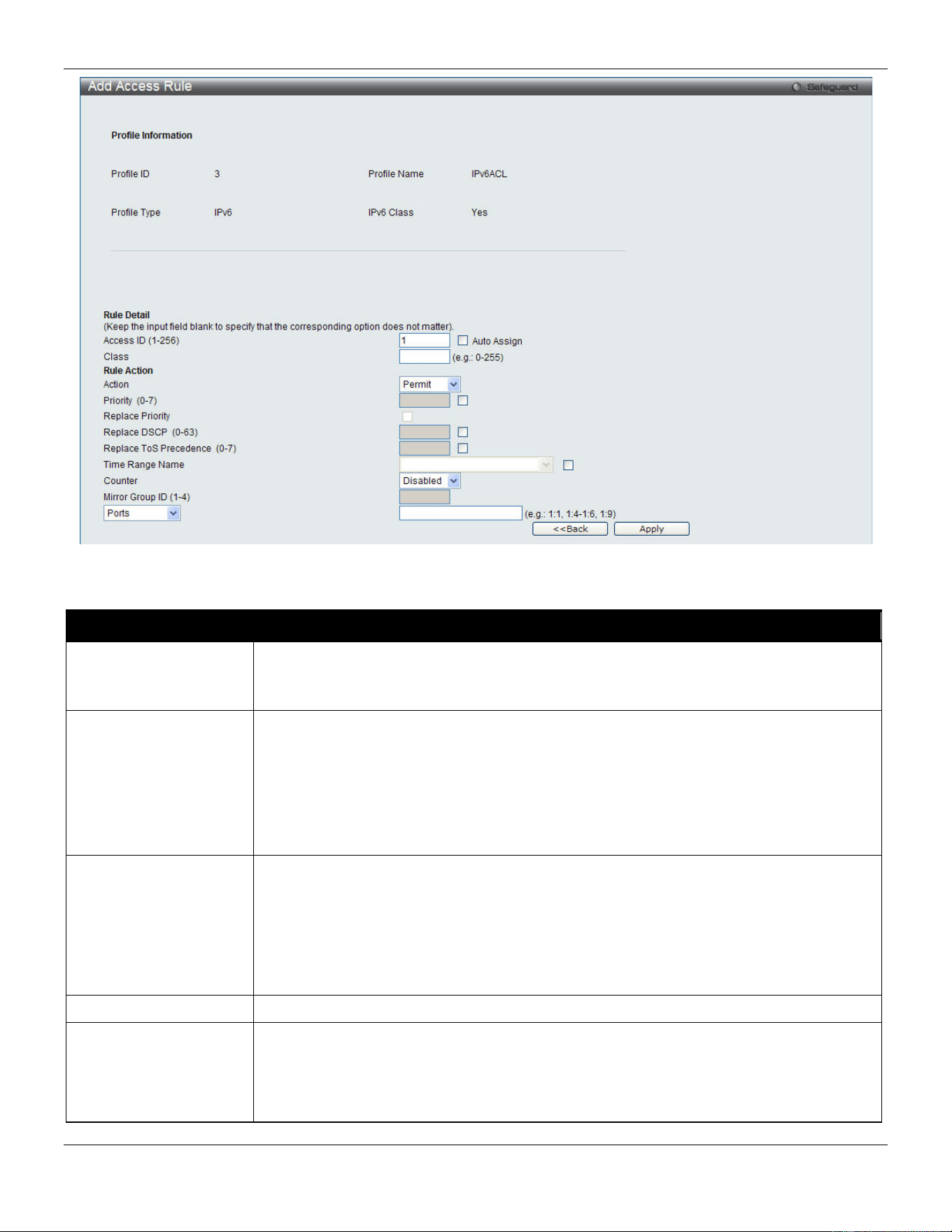
xStack® DGS-3420 Series Layer 2 Managed Stackable Gigabit Switch Web UI Reference Guide
237
Figure 7-16 Add Access Rule (IPv6 ACL)
The fields that can be configured are described below:
Parameter Description
Access ID (1-256)
Type in a unique identifier number for this access. This value can be set from 1 to 256.
Auto Assign – Tick the check box will instruct the Switch to automatically assign an
Access ID for the rule being created.
Action Select Permit to specify that the packets that match the access profile are forwarded by
the Switch, according to any additional rule added (see below).
Select Deny to specify that packets that match the access profile are not forwarded by
the Switch and will be filtered.
Select Mirror to specify that packets that match the access profile are mirrored to a port
defined in the config mirror port command. Port Mirroring must be enabled and a target
port must be set.
Priority (0-7)
Tick the corresponding check box to re-write the 802.1p default priority of a packet to the
value entered in the Priority field, which meets the criteria specified previously in this
command, before forwarding it on to the specified CoS queue. Otherwise, a packet will
have its incoming 802.1p user priority re-written to its original value before being
forwarded by the Switch.
For more information on priority queues, CoS queues and mapping for 802.1p, see the
QoS section of this manual.
Replace Priority
Tick this check box to replace the Priority value in the adjacent field.
Replace DSCP (0-63)
Select this option to instruct the Switch to replace the DSCP value (in a packet that
meets the selected criteria) with the value entered in the adjacent field. When an ACL
rule is added to change both the priority and DSCP of an IPv6 packet, only one of them
can be modified due to a chip limitation. Currently the priority is changed when both the
priority and DSCP are set to be modified.

xStack® DGS-3420 Series Layer 2 Managed Stackable Gigabit Switch Web UI Reference Guide
238
Replace ToS
Precedence (0-7)
Specify that the IP precedence of the outgoing packet is changed with the new value. If
used without an action priority, the packet is sent to the default TC.
Time Range Name
Tick the check box and enter the name of the Time Range settings that has been
previously configured in the Time Range Settings window. This will set specific times
when this access rule will be implemented on the Switch.
Counter
Here the user can select the counter. By checking the counter, the administrator can see
how many times that the rule was hit.
Ports
When a range of ports is to be configured, the Auto Assign check box MUST be ticked in
the Access ID field of this window. If not, the user will be presented with an error
message and the access rule will not be configured. Ticking the All Ports check box will
denote all ports on the Switch.
VLAN Name
Specify the VLAN name to apply to the access rule.
VLAN ID
Specify the VLAN ID to apply to the access rule.
Click the <<Back button to discard the changes made and return to the previous page.
Click the Apply button to accept the changes made.
After clicking the Show Details button in the Access Rule List, the following page will appear:
Figure 7-17 Access Rule Detail Information (IPv6 ACL)
Click the Show All Rules button to navigate back to the Access Rule List.
Adding a Packet Content ACL Profile
The window shown below is the Add ACL Profile window for Packet Content: To use specific filtering masks in this ACL
profile, click the packet filtering mask field to highlight it red. This will add more filed to the mask.
After clicking the Add ACL Profile button, the following page will appear:
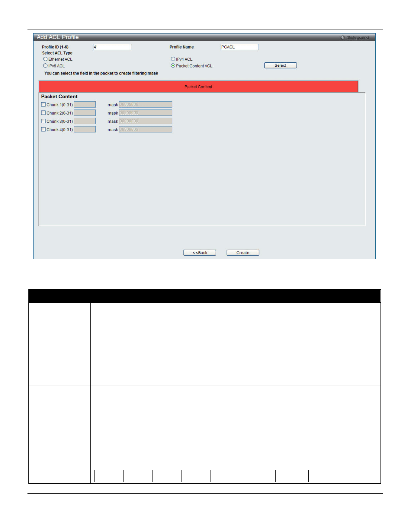
xStack® DGS-3420 Series Layer 2 Managed Stackable Gigabit Switch Web UI Reference Guide
239
.
Figure 7-18 Add ACL Profile (Packet Content ACL)
The fields that can be configured are described below:
Parameter Description
Profile ID (1-6) Enter a unique identifier number for this profile set. This value can be set from 1 to 6.
Select ACL Type
Select profile based on Ethernet (MAC Address), IPv4 address, IPv6 address, or packet
content. This will change the window according to the requirements for the type of profile.
Select Ethernet ACL to instruct the Switch to examine the layer 2 part of each packet header.
Select IPv4 ACL to instruct the Switch to examine the IPv4 address in each frame's header.
Select IPv6 ACL to instruct the Switch to examine the IPv6 address in each frame's header.
Select Packet Content to instruct the Switch to examine the packet content in each frame’s
header.
Packet Content
Allows users to examine up to 4 specified offset_chunks within a packet at one time and
specifies the frame content offset and mask. There are 4 chunk offsets and masks that can be
configured. A chunk mask presents 4 bytes. 4 offset_chunks can be selected from a possible
32 predefined offset_chunks as described below:
offset_chunk_1,
offset_chunk_2,
offset_chunk_3,
offset_chunk_4.
chunk0 chunk1 chunk2 …… chunk29 chunk30 chunk31
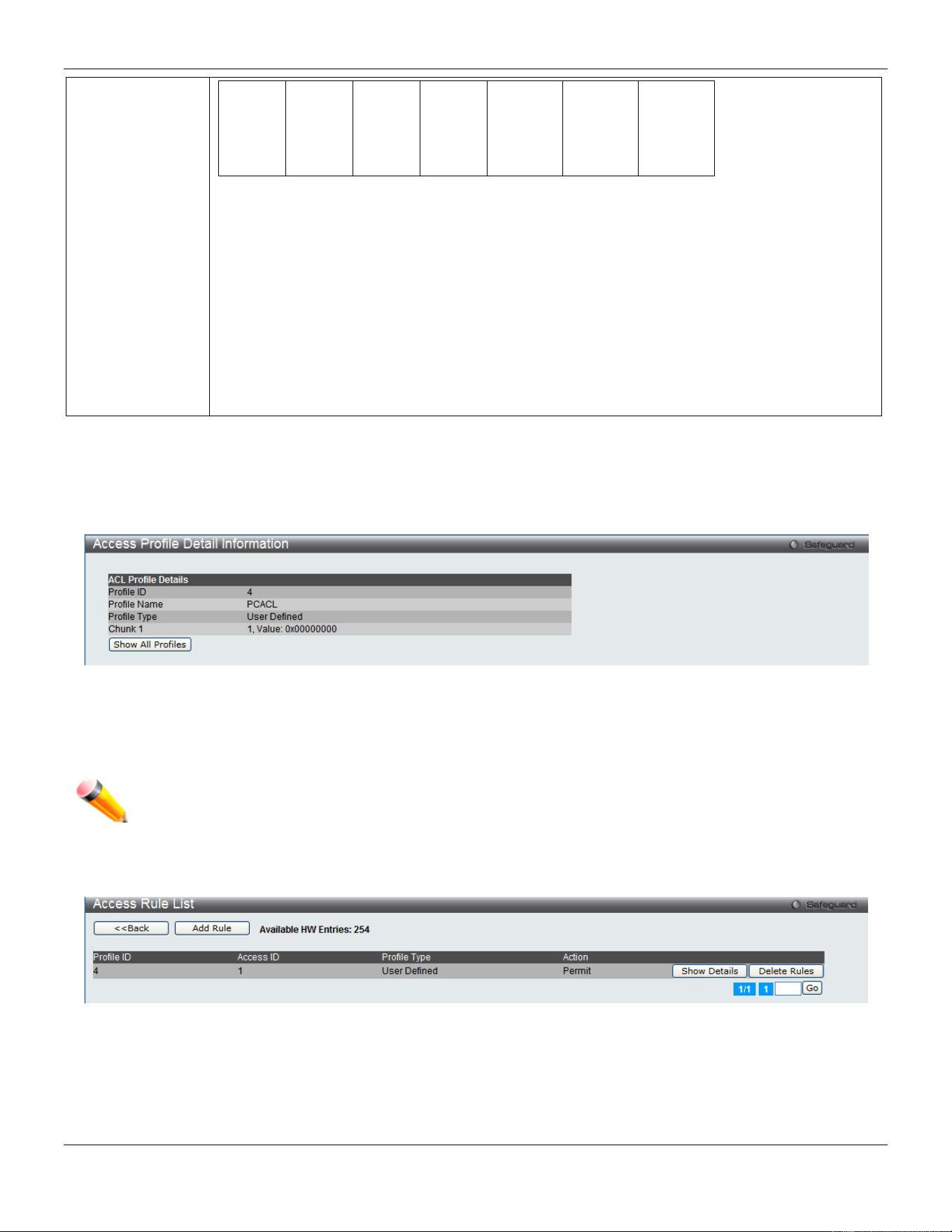
xStack® DGS-3420 Series Layer 2 Managed Stackable Gigabit Switch Web UI Reference Guide
240
B126,
B127,
B0,
B1
B2,
B3,
B4,
B5
B6,
B7,
B8,
B9
…… B114,
B115,
B116,
B117
B118,
B119,
B120,
B121
B122,
B123,
B124,
B125
Example:
offset_chunk_1 0 0xffffffff will match packet byte offset 126,127,0,1
offset_chunk_1 0 0x0000ffff will match packet byte offset,0,1
NOTE: Only one packet_content_mask profile can be created.
With this advanced unique Packet Content Mask (also known as Packet Content Access Control List -
ACL), the D-Link xStack
®
switch family can effectively mitigate some network attacks like the
common ARP Spoofing attack that is wide spread today. This is why the Packet Content ACL
is able to inspect any specified content of a packet in different protocol layers.
Click the Select button to select an ACL type.
Click the <<Back button to discard the changes made and return to the previous page.
Click the Create button to create a profile.
After clicking the Show Details button, the following page will appear:
Figure 7-19 Access Profile Detail Information (Packet Content ACL)
Click the Show All Profiles button to navigate back to the Access Profile List window.
NOTE: Address Resolution Protocol (ARP) is the standard for finding a host’s hardware address (MAC
address). However, ARP is vulnerable as it can be easily spoofed and utilized to attack a LAN (i.e.
an ARP spoofing attack). For a more detailed explanation on how ARP protocol works and how to
employ D-Link’s unique Packet Content ACL to prevent ARP spoofing attack, please see Appendix
E at the end of this manual.
After clicking the Add/View Rules button, the following page will appear:
Figure 7-20 Access Rule List (Packet Content ACL)
Click the <<Back button to return to the previous page.
Click the Add Rule button to create a new ACL rule in this profile.
Click the Show Details button to view more information about the specific rule created.
Click the Delete Rules button to remove the specific entry.
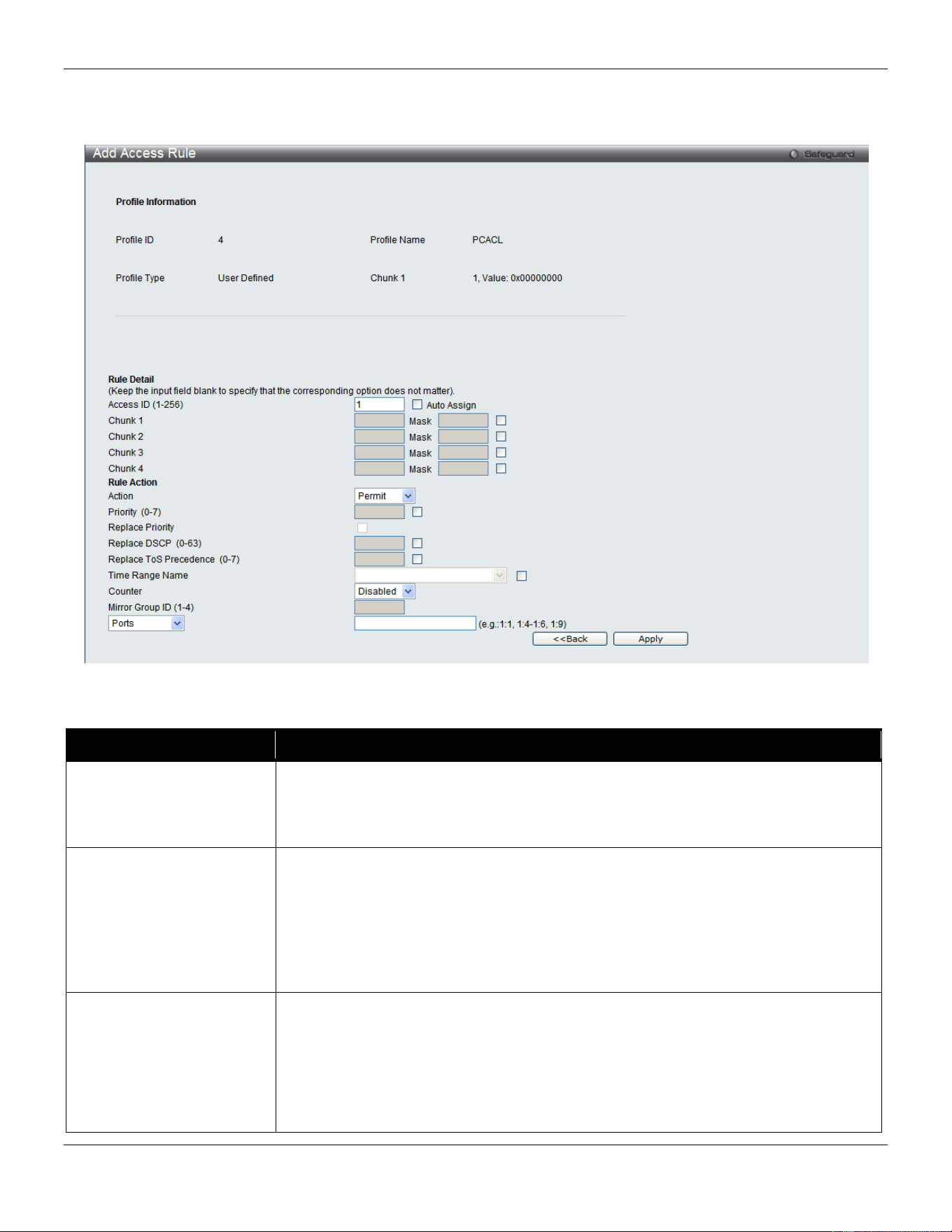
xStack® DGS-3420 Series Layer 2 Managed Stackable Gigabit Switch Web UI Reference Guide
241
Enter a page number and click the Go button to navigate to a specific page when multiple pages exist.
After clicking the Add Rule button, the following page will appear:
Figure 7-21 Add Access Rule (Packet Content ACL)
The fields that can be configured are described below:
Parameter Description
Access ID (1-256)
Type in a unique identifier number for this access. This value can be set from 1 to
256.
Auto Assign – Tick the check box will instruct the Switch to automatically assign an
Access ID for the rule being created.
Action Select Permit to specify that the packets that match the access profile are forwarded
by the Switch, according to any additional rule added (see below).
Select Deny to specify that the packets that match the access profile are not
forwarded by the Switch and will be filtered.
Select Mirror to specify that packets that match the access profile are mirrored to a
port defined in the config mirror port command. Port Mirroring must be enabled and a
target port must be set.
Priority (0-7)
Tick the corresponding check box if you want to re-write the 802.1p default priority of
a packet to the value entered in the Priority field, which meets the criteria specified
previously in this command, before forwarding it on to the specified CoS queue.
Otherwise, a packet will have its incoming 802.1p user priority re-written to its original
value before being forwarded by the Switch.
For more information on priority queues, CoS queues and mapping for 802.1p, see
the QoS section of this manual.
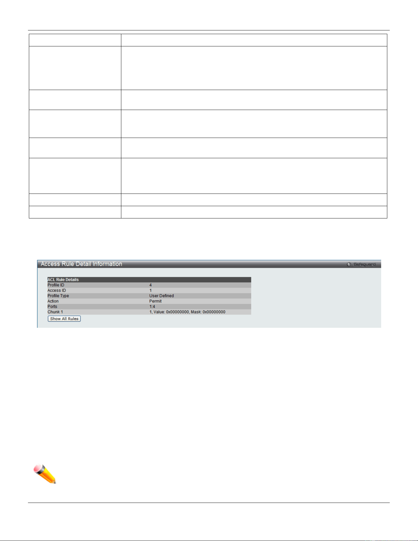
xStack® DGS-3420 Series Layer 2 Managed Stackable Gigabit Switch Web UI Reference Guide
242
Replace Priority
Tick this check box to replace the Priority value in the adjacent field.
Replace DSCP (0-63)
Select this option to instruct the Switch to replace the DSCP value (in a packet that
meets the selected criteria) with the value entered in the adjacent field. When an ACL
rule is added to change both the priority and DSCP of an IPv4 packet, only one of
them can be modified due to a chip limitation. Currently the priority is changed when
both the priority and DSCP are set to be modified.
Replace ToS Precedence
(0-7)
Specify that the IP precedence of the outgoing packet is changed with the new value.
If used without an action priority, the packet is sent to the default TC.
Time Range Name
Tick the check box and enter the name of the Time Range settings that has been
previously configured in the Time Range Settings window. This will set specific
times when this access rule will be implemented on the Switch.
Counter
Here the user can select the counter. By checking the counter, the administrator can
see how many times that the rule was hit.
Ports
When a range of ports is to be configured, the Auto Assign check box MUST be
ticked in the Access ID field of this window. If not, the user will be presented with an
error message and the access rule will not be configured. Ticking the All Ports check
box will denote all ports on the Switch.
VLAN Name
Specify the VLAN name to apply to the access rule.
VLAN ID
Specify the VLAN ID to apply to the access rule.
Click the <<Back button to discard the changes made and return to the previous page.
Click the Apply button to accept the changes made.
After clicking the Show Details button in the Access Rule List, the following page will appear:
Figure 7-22 Access Rule Detail Information (Packet Content ACL)
Click the Show All Rules button to navigate back to the Access Rule List.
CPU Access Profile List
Due to a chipset limitation and needed extra switch security, the Switch incorporates CPU Interface filtering. This
added feature increases the running security of the Switch by enabling the user to create a list of access rules for
packets destined for the Switch’s CPU interface. Employed similarly to the Access Profile feature previously mentioned,
CPU interface filtering examines Ethernet, IP and Packet Content Mask packet headers destined for the CPU and will
either forward them or filter them, based on the user’s implementation. As an added feature for the CPU Filtering, the
Switch allows the CPU filtering mechanism to be enabled or disabled globally, permitting the user to create various lists
of rules without immediately enabling them.
NOTE: CPU Interface Filtering is used to control traffic access to the switch directly such as protocols
transition or management access. A CPU interface filtering rule won’t impact normal L2/3 traffic
forwarding. However, an improper CPU interface filtering rule may cause the network to become
unstable.
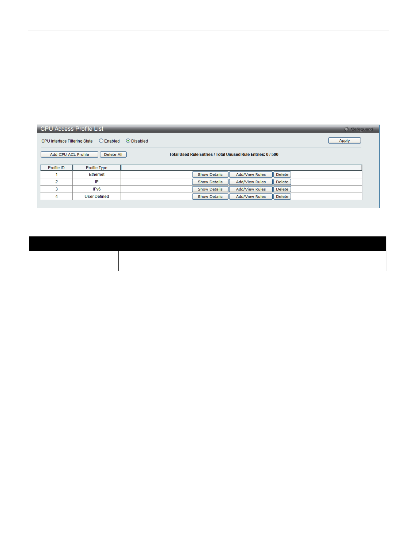
xStack® DGS-3420 Series Layer 2 Managed Stackable Gigabit Switch Web UI Reference Guide
243
To view CPU Access Profile List window, click ACL > CPU Access Profile List as shown below:
Creating an access profile for the CPU is divided into two basic parts. The first is to specify which part or parts of a
frame the Switch will examine, such as the MAC source address or the IP destination address. The second part is
entering the criteria the Switch will use to determine what to do with the frame. The entire process is described below.
Users may globally enable or disable the CPU Interface Filtering State mechanism by using the radio buttons to
change the running state. Choose Enabled to enable CPU packets to be scrutinized by the Switch and Disabled to
disallow this scrutiny.
Figure 7-23 CPU Access Profile List window
The fields that can be configured are described below:
Parameter Description
CPU Interface Filtering
State
Here the user can enable or disable the CPU interface filtering state.
Click the Apply button to accept the changes made.
Click the Add CPU ACL Profile button to add an entry to the CPU ACL Profile List.
Click the Delete All button to remove all access profiles from this table.
Click the Show Details button to display the information of the specific profile ID entry.
Click the Add/View Rules button to view or add CPU ACL rules within the specified profile ID.
Click the Delete button to remove the specific entry.
There are four Add CPU ACL Profile windows;
• one for Ethernet (or MAC address-based) profile configuration,
• one for IPv6 address-based profile configuration,
• one for IPv4 address-based profile configuration, and
• one for packet content profile configuration.
Adding a CPU Ethernet ACL Profile
The window shown below is the Add CPU ACL Profile window for Ethernet. To use specific filtering masks in this ACL
profile, click the packet filtering mask field to highlight it red. This will add more filed to the mask.
After clicking the Add CPU ACL Profile button, the following page will appear:
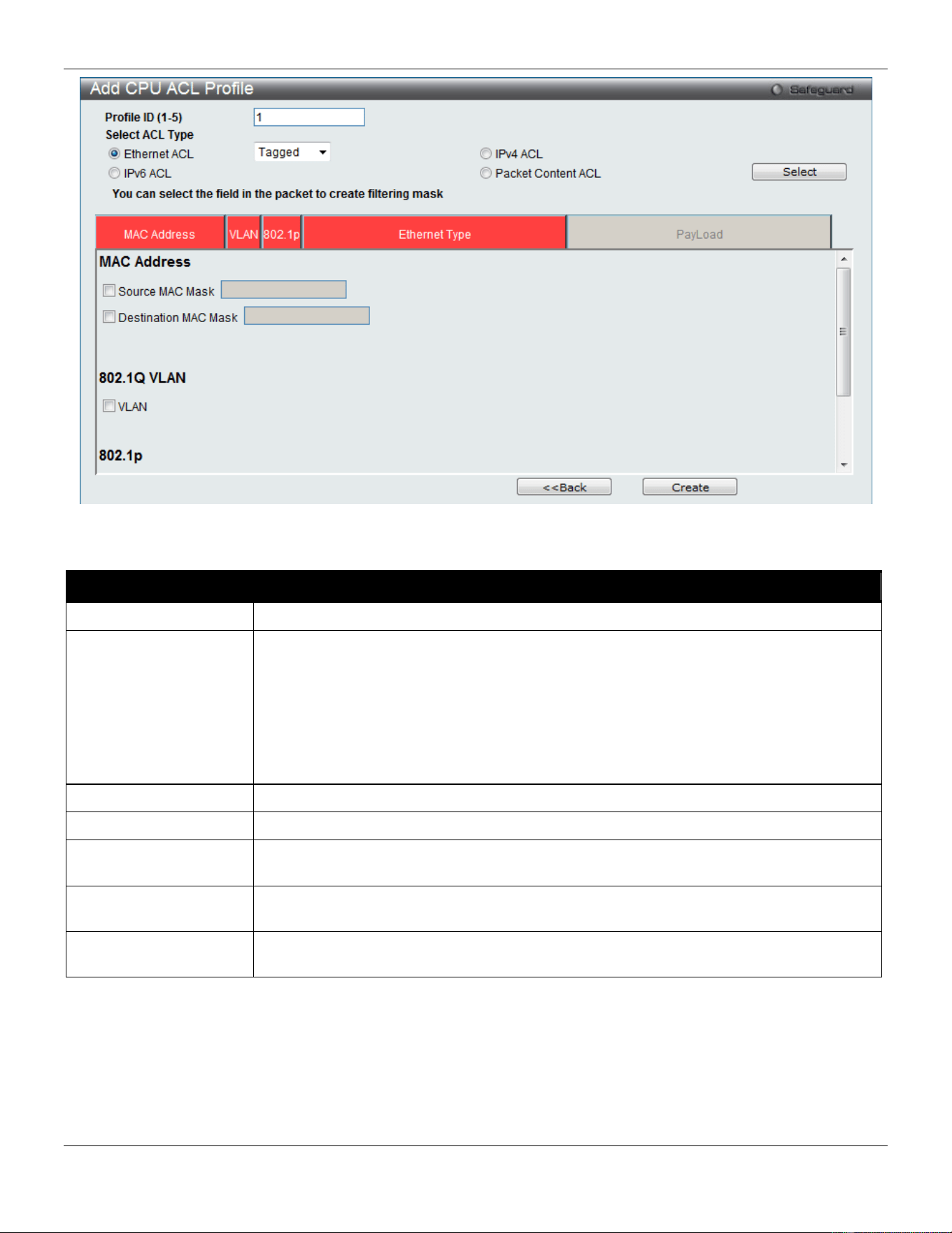
xStack® DGS-3420 Series Layer 2 Managed Stackable Gigabit Switch Web UI Reference Guide
244
Figure 7-24 Add CPU ACL Profile (Ethernet ACL)
The fields that can be configured are described below:
Parameter Description
Profile ID (1-5)
Enter a unique identifier number for this profile set. This value can be set from 1 to 5.
Select ACL Type
Select profile based on Ethernet (MAC Address), IPv4 address, IPv6 address, or packet
content mask. This will change the window according to the requirements for the type of
profile.
Select Ethernet to instruct the Switch to examine the layer 2 part of each packet header.
Select IPv4 to instruct the Switch to examine the IP address in each frame's header.
Select IPv6 to instruct the Switch to examine the IP address in each frame's header.
Select Packet Content Mask to specify a mask to hide the content of the packet header.
Source MAC Mask
Enter a MAC address mask for the source MAC address.
Destination MAC Mask
Enter a MAC address mask for the destination MAC address.
802.1Q VLAN
Selecting this option instructs the Switch to examine the VLAN identifier of each packet
header and use this as the full or partial criterion for forwarding.
802.1p
Selecting this option instructs the Switch to specify that the access profile will apply only
to packets with this 802.1p priority value.
Ethernet Type
Selecting this option instructs the Switch to examine the Ethernet type value in each
frame's header.
Click the Select button to select a CPU ACL type.
Click the Create button to create a profile.
Click the <<Back button to discard the changes made and return to the previous page.
After clicking the Show Details button, the following page will appear:
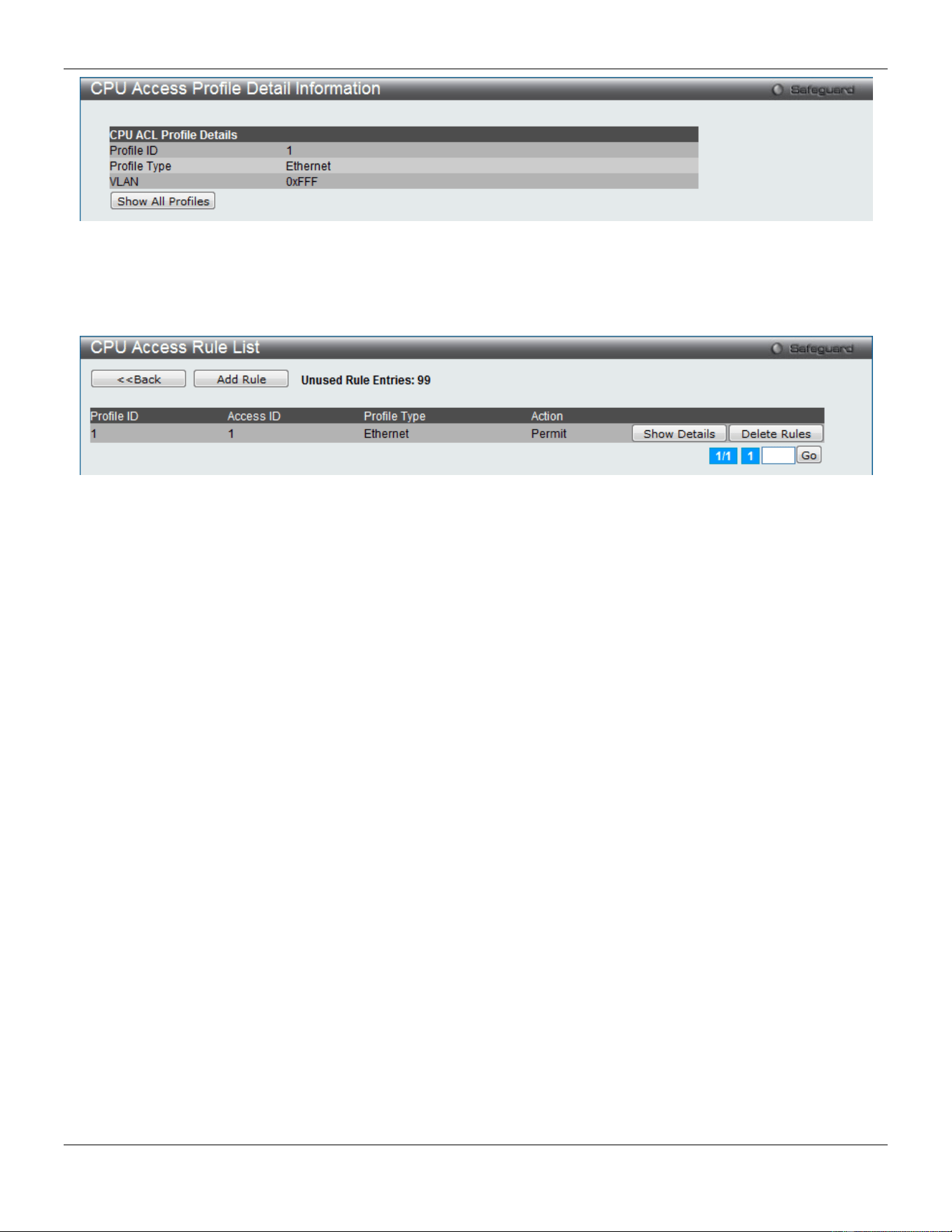
xStack® DGS-3420 Series Layer 2 Managed Stackable Gigabit Switch Web UI Reference Guide
245
Figure 7-25 CPU Access Profile Detail Information (Ethernet ACL)
Click the Show All Profiles button to navigate back to the CPU ACL Profile List window.
After clicking the Add/View Rules button, the following page will appear:
Figure 7-26 CPU Access Rule List (Ethernet ACL)
Click the Add Rule button to create a new CPU ACL rule in this profile.
Click the <<Back button to return to the previous page.
Click the Show Details button to view more information about the specific rule created.
Click the Delete Rules button to remove the specific entry.
Enter a page number and click the Go button to navigate to a specific page when multiple pages exist.
After clicking the Add Rule button, the following page will appear:
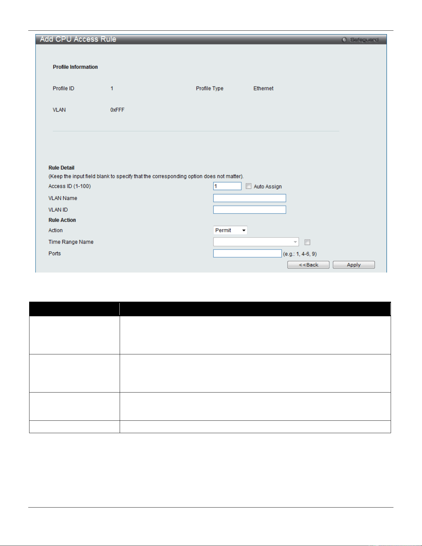
xStack® DGS-3420 Series Layer 2 Managed Stackable Gigabit Switch Web UI Reference Guide
246
Figure 7-27 Add CPU Access Rule (Ethernet ACL)
The fields that can be configured are described below:
Parameter Description
Access ID (1-100)
Type in a unique identifier number for this access. This value can be set from 1 to
100.
Auto Assign – Tick the check box will instruct the Switch to automatically assign an
Access ID for the rule being created.
Action Select Permit to specify that the packets that match the access profile are forwarded
by the Switch, according to any additional rule added (see below).
Select Deny to specify that the packets that match the access profile are not
forwarded by the Switch and will be filtered.
Time Range Name
Tick the check box and enter the name of the Time Range settings that has been
previously configured in the Time Range Settings window. This will set specific times
when this access rule will be implemented on the Switch.
Ports
Ticking the All Ports check box will denote all ports on the Switch.
Click the Apply button to accept the changes made.
Click the <<Back button to discard the changes made and return to the previous page.
After clicking the Show Details button in the CPU Access Rule List, the following page will appear:
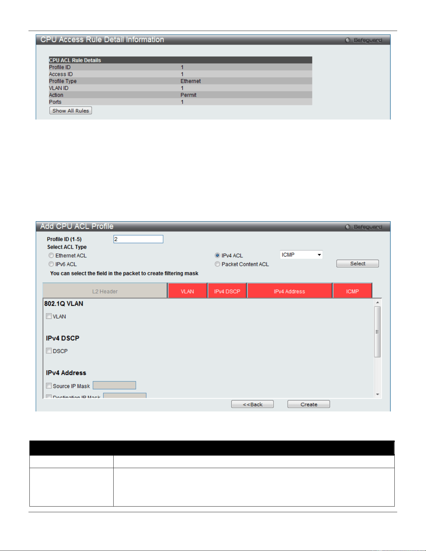
xStack® DGS-3420 Series Layer 2 Managed Stackable Gigabit Switch Web UI Reference Guide
247
Figure 7-28 CPU Access Rule Detail Information (Ethernet ACL)
Click the Show All Rules button to navigate back to the CPU Access Rule List.
Adding a CPU IPv4 ACL Profile
The window shown below is the Add CPU ACL Profile window for IP (IPv4). To use specific filtering masks in this ACL
profile, click the packet filtering mask field to highlight it red. This will add more filed to the mask.
After clicking the Add CPU ACL Profile button, the following page will appear:
Figure 7-29 Add CPU ACL Profile (IPv4 ACL)
The fields that can be configured are described below:
Parameter Description
Profile ID (1-5)
Enter a unique identifier number for this profile set. This value can be set from 1 to 5.
Select ACL Type
Select profile based on Ethernet (MAC Address), IPv4 address, IPv6 address, or packet
content mask. This will change the menu according to the requirements for the type of
profile.
Select Ethernet to instruct the Switch to examine the layer 2 part of each packet header.

xStack® DGS-3420 Series Layer 2 Managed Stackable Gigabit Switch Web UI Reference Guide
248
Select IPv4 to instruct the Switch to examine the IP address in each frame's header.
Select IPv6 to instruct the Switch to examine the IP address in each frame's header.
Select Packet Content Mask to specify a mask to hide the content of the packet header.
802.1Q VLAN
Selecting this option instructs the Switch to examine the VLAN part of each packet
header and use this as the, or part of the criterion for forwarding.
IPv4 DSCP
Selecting this option instructs the Switch to examine the DiffServ Code part of each
packet header and use this as the, or part of the criterion for forwarding.
Source IP Mask
Enter an IP address mask for the source IP address, e.g. 255.255.255.255.
Destination IP Mask
Enter an IP address mask for the destination IP address, e.g. 255.255.255.255.
Protocol
Selecting this option instructs the Switch to examine the protocol type value in each
frame's header. You must then specify what protocol(s) to include according to the
following guidelines:
Select ICMP to instruct the Switch to examine the Internet Control Message Protocol
(ICMP) field in each frame's header.
Select Type to further specify that the access profile will apply an ICMP type value, or
specify Code to further specify that the access profile will apply an ICMP code value.
Select IGMP to instruct the Switch to examine the Internet Group Management Protocol
(IGMP) field in each frame's header.
Select Type to further specify that the access profile will apply an IGMP type value.
Select TCP to use the TCP port number contained in an incoming packet as the
forwarding criterion. Selecting TCP requires a source port mask and/or a destination port
mask is to be specified. The user may also identify which flag bits to filter. Flag bits are
parts of a packet that determine what to do with the packet. The user may filter packets
by filtering certain flag bits within the packets, by checking the boxes corresponding to
the flag bits of the TCP field. The user may choose between urg (urgent), ack
(acknowledgement), psh (push), rst (reset), syn (synchronize), fin (finish).
src port mask - Specify a TCP port mask for the source port in hex form (hex 0x0-0xffff),
which you wish to filter.
dst port mask - Specify a TCP port mask for the destination port in hex form (hex 0x0-
0xffff) which you wish to filter.
Select UDP to use the UDP port number contained in an incoming packet as the
forwarding criterion. Selecting UDP requires that you specify a source port mask and/or
a destination port mask.
src port mask - Specify a UDP port mask for the source port in hex form (hex 0x0-0xffff).
dst port mask - Specify a UDP port mask for the destination port in hex form (hex 0x0-
0xffff).
Select Protocol ID - Enter a value defining the protocol ID in the packet header to mask.
Specify the protocol ID mask in hex form (hex 0x0-0xff).
Protocol ID Mask – Specify that the rule applies to the IP Protocol ID Traffic.
User Define – Specify the L4 part mask.
Click the Select button to select a CPU ACL type.
Click the Create button to create a profile.
Click the <<Back button to discard the changes made and return to the previous page.
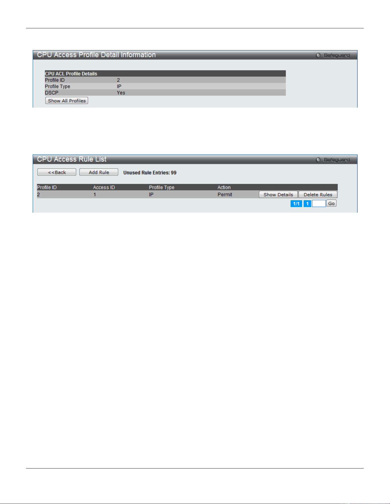
xStack® DGS-3420 Series Layer 2 Managed Stackable Gigabit Switch Web UI Reference Guide
249
After clicking the Show Details button, the following page will appear:
Figure 7-30 CPU Access Profile Detail Information (IPv4 ACL)
Click the Show All Profiles button to navigate back to the CPU ACL Profile List window.
After clicking the Add/View Rules button, the following page will appear:
Figure 7-31 CPU Access Rule List (IPv4 ACL)
Click the Add Rule button to create a new CPU ACL rule in this profile.
Click the <<Back button to return to the previous page.
Click the Show Details button to view more information about the specific rule created.
Click the Delete Rules button to remove the specific entry.
Enter a page number and click the Go button to navigate to a specific page when multiple pages exist.
After clicking the Add Rule button, the following page will appear:
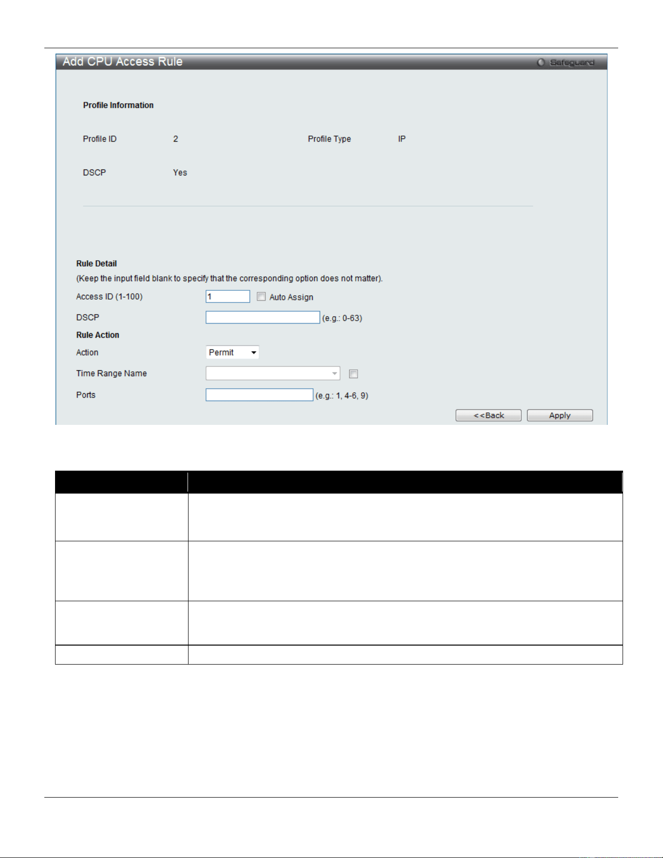
xStack® DGS-3420 Series Layer 2 Managed Stackable Gigabit Switch Web UI Reference Guide
250
Figure 7-32 Add CPU Access Rule (IPv4 ACL)
The fields that can be configured are described below:
Parameter Description
Access ID (1-100)
Type in a unique identifier number for this access. This value can be set from 1 to 100.
Auto Assign – Tick the check box will instruct the Switch to automatically assign an
Access ID for the rule being created.
Action Select Permit to specify that the packets that match the access profile are forwarded by
the Switch, according to any additional rule added (see below).
Select Deny to specify that the packets that match the access profile are not forwarded
by the Switch and will be filtered.
Time Range Name
Tick the check box and enter the name of the Time Range settings that has been
previously configured in the Time Range Settings window. This will set specific times
when this access rule will be implemented on the Switch.
Ports
Ticking the All Ports check box will denote all ports on the Switch.
Click the Apply button to accept the changes made.
Click the <<Back button to discard the changes made and return to the previous page.
After clicking the Show Details button in the CPU Access Rule List, the following page will appear:
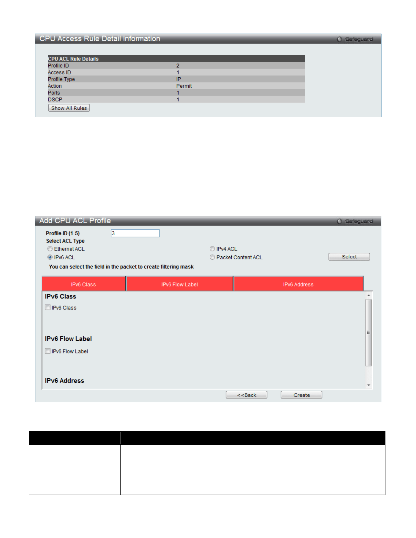
xStack® DGS-3420 Series Layer 2 Managed Stackable Gigabit Switch Web UI Reference Guide
251
Figure 7-33 CPU Access Rule Detail Information (IPv4 ACL)
Click the Show All Rules button to navigate back to the CPU Access Rule List.
Adding a CPU IPv6 ACL Profile
The window shown below is the Add CPU ACL Profile window for IPv6. To use specific filtering masks in this ACL
profile, click the packet filtering mask field to highlight it red. This will add more filed to the mask.
After clicking the Add CPU ACL Profile button, the following page will appear:
Figure 7-34 Add CPU ACL Profile (IPv6 ACL)
The fields that can be configured are described below:
Parameter Description
Profile ID (1-5)
Enter a unique identifier number for this profile set. This value can be set from 1 to5.
Select ACL Type
Select profile based on Ethernet (MAC Address), IPv4 address, IPv6 address, or
packet content mask. This will change the menu according to the requirements for
the type of profile.
Select Ethernet to instruct the Switch to examine the layer 2 part of each packet
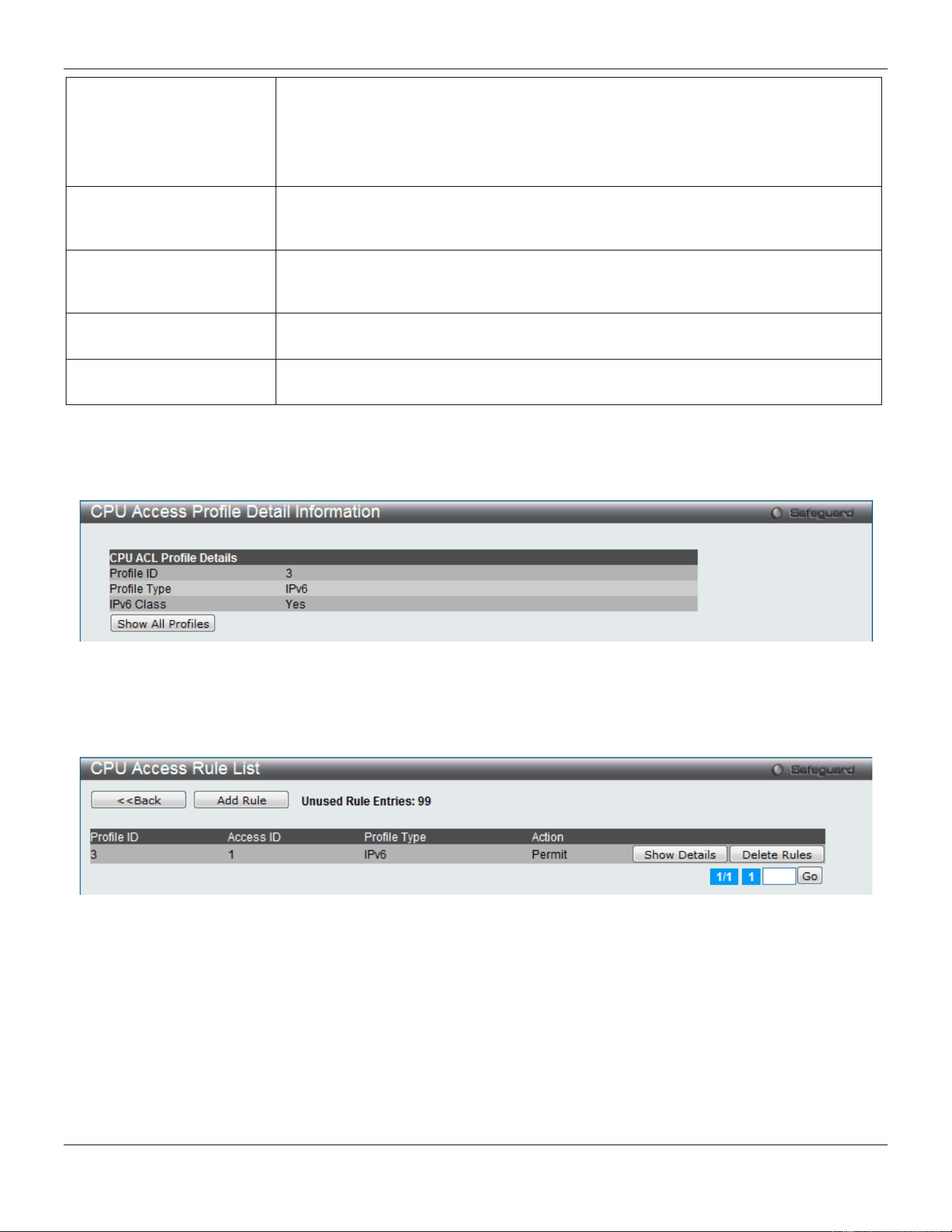
xStack® DGS-3420 Series Layer 2 Managed Stackable Gigabit Switch Web UI Reference Guide
252
header.
Select IPv4 to instruct the Switch to examine the IP address in each frame's header.
Select IPv6 to instruct the Switch to examine the IP address in each frame's header.
Select Packet Content Mask to specify a mask to hide the content of the packet
header.
IPv6 Class Checking this field will instruct the Switch to examine the class field of the IPv6
header. This class field is a part of the packet header that is similar to the Type of
Service (ToS) or Precedence bits field in IPv4.
IPv6 Flow Label Checking this field will instruct the Switch to examine the flow label field of the IPv6
header. This flow label field is used by a source to label sequences of packets such
as non-default quality of service or real time service packets.
IPv6 Source Mask
The user may specify an IPv6 address mask for the source IPv6 address by checking
the corresponding box and entering the IPv6 address mask.
IPv6 Destination Mask
The user may specify an IPv6 address mask for the destination IPv6 address by
checking the corresponding box and entering the IPv6 address mask.
Click the Select button to select a CPU ACL type. Click the Create button to create a profile.
Click the <<Back button to discard the changes made and return to the previous page.
After clicking the Show Details button, the following page will appear:
Figure 7-35 CPU Access Profile Detail Information (IPv6 ACL)
Click the Show All Profiles button to navigate back to the CPU ACL Profile List window.
After clicking the Add/View Rules button, the following page will appear:
Figure 7-36 CPU Access Rule List (IPv6 ACL)
Click the Add Rule button to create a new CPU ACL rule in this profile.
Click the <<Back button to return to the previous page.
Click the Show Details button to view more information about the specific rule created.
Click the Delete Rules button to remove the specific entry.
Enter a page number and click the Go button to navigate to a specific page when multiple pages exist.
After clicking the Add Rule button, the following page will appear:
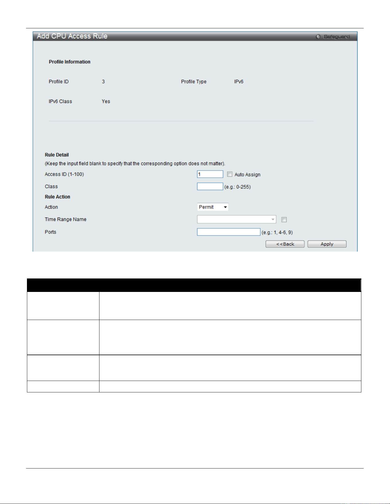
xStack® DGS-3420 Series Layer 2 Managed Stackable Gigabit Switch Web UI Reference Guide
253
Figure 7-37 Add CPU Access Rule (IPv6 ACL)
The fields that can be configured are described below:
Parameter Description
Access ID (1-100)
Enter a unique identifier number for this access. This value can be set from 1 to 100.
Auto Assign – Tick the check box will instruct the Switch to automatically assign an
Access ID for the rule being created.
Action Select Permit to specify that the packets that match the access profile are forwarded by
the Switch, according to any additional rule added (see below).
Select Deny to specify that the packets that match the access profile are not forwarded by
the Switch and will be filtered.
Time Range Name
Tick the check box and enter the name of the Time Range settings that has been
previously configured in the Time Range Settings window. This will set specific times
when this access rule will be implemented on the Switch.
Ports
Ticking the All Ports check box will denote all ports on the Switch.
Click the Apply button to accept the changes made.
Click the <<Back button to discard the changes made and return to the previous page.
After clicking the Show Details button in the CPU Access Rule List, the following page will appear:
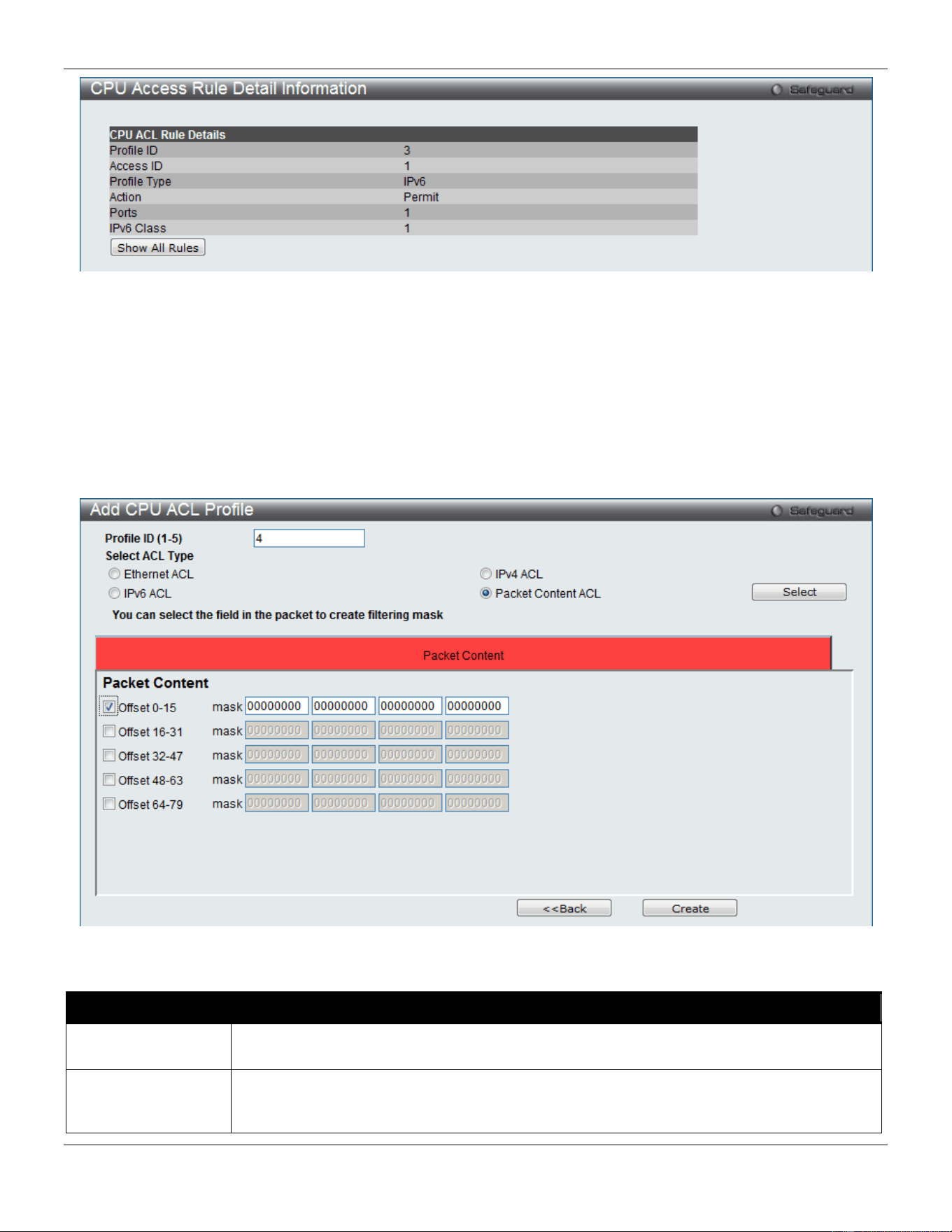
xStack® DGS-3420 Series Layer 2 Managed Stackable Gigabit Switch Web UI Reference Guide
254
Figure 7-38 CPU Access Rule Detail Information (IPv6 ACL)
Click the Show All Rules button to navigate back to the CPU Access Rule List.
Adding a CPU Packet Content ACL Profile
The window shown below is the Add CPU ACL Profile window for Packet Content. To use specific filtering masks in
this ACL profile, click the packet filtering mask field to highlight it red. This will add more filed to the mask.
After clicking the Add CPU ACL Profile button, the following page will appear:
Figure 7-39 Add CPU ACL Profile (Packet Content ACL)
The fields that can be configured are described below:
Parameter Description
Profile ID (1-5)
Here the user can enter a unique identifier number for this profile set. This value can be set
from 1 to5.
Select ACL Type
Select profile based on Ethernet (MAC Address), IPv4 address, IPv6 address, or packet
content mask. This will change the menu according to the requirements for the type of
profile.
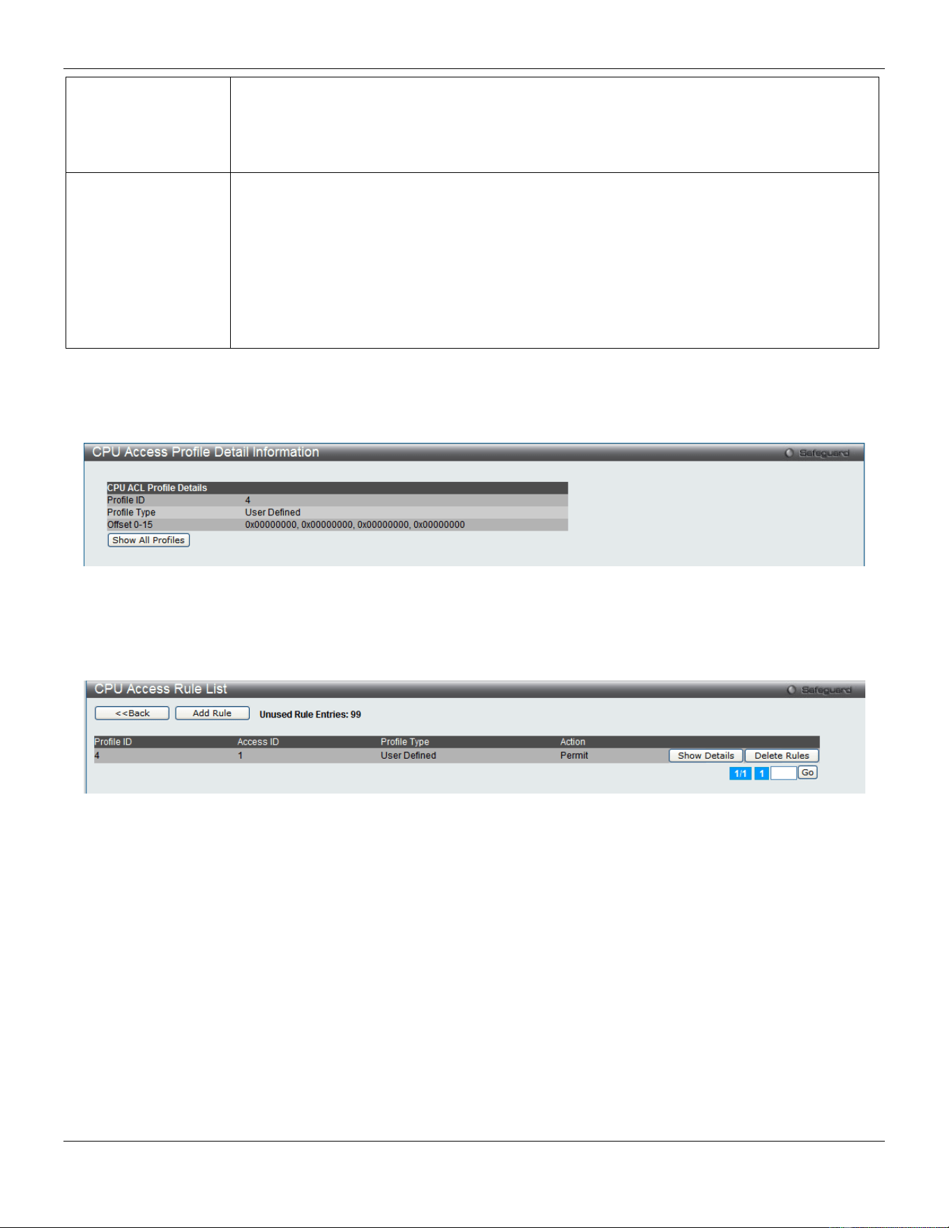
xStack® DGS-3420 Series Layer 2 Managed Stackable Gigabit Switch Web UI Reference Guide
255
Select Ethernet to instruct the Switch to examine the layer 2 part of each packet header.
Select IPv4 to instruct the Switch to examine the IP address in each frame's header.
Select IPv6 to instruct the Switch to examine the IP address in each frame's header.
Select Packet Content Mask to specify a mask to hide the content of the packet header.
Offset
This field will instruct the Switch to mask the packet header beginning with the offset value
specified:
0-15 - Enter a value in hex form to mask the packet from the beginning of the packet to the
15th byte.
16-31 – Enter a value in hex form to mask the packet from byte 16 to byte 31.
32-47 – Enter a value in hex form to mask the packet from byte 32 to byte 47.
48-63 – Enter a value in hex form to mask the packet from byte 48 to byte 63.
64-79 – Enter a value in hex form to mask the packet from byte 64 to byte 79.
Click the Select button to select a CPU ACL type. Click the Create button to create a profile.
Click the <<Back button to discard the changes made and return to the previous page.
After clicking the Show Details button, the following page will appear:
Figure 7-40 CPU Access Profile Detail Information (Packet Content ACL)
Click the Show All Profiles button to navigate back to the CPU ACL Profile List window.
After clicking the Add/View Rules button, the following page will appear:
Figure 7-41 CPU Access Rule List (Packet Content ACL)
Click the Add Rule button to create a new CPU ACL rule in this profile.
Click the <<Back button to return to the previous page.
Click the Show Details button to view more information about the specific rule created.
Click the Delete Rules button to remove the specific entry.
Enter a page number and click the Go button to navigate to a specific page when multiple pages exist.
After clicking the Add Rule button, the following page will appear:
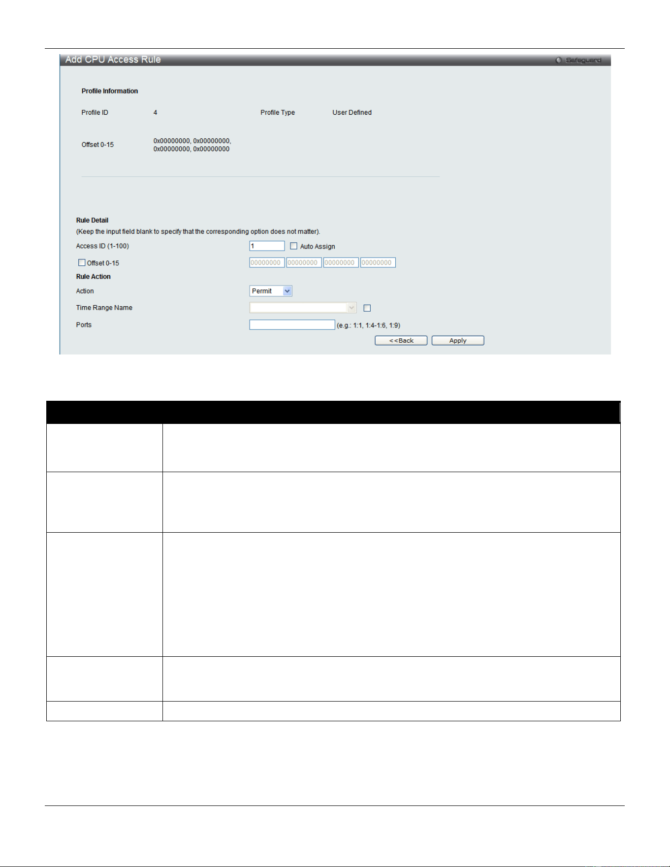
xStack® DGS-3420 Series Layer 2 Managed Stackable Gigabit Switch Web UI Reference Guide
256
Figure 7-42 Add CPU Access Rule (Packet Content ACL)
The fields that can be configured are described below:
Parameter Description
Access ID (1-100)
Type in a unique identifier number for this access. This value can be set from 1 to 100.
Auto Assign – Tick the check box will instruct the Switch to automatically assign an Access
ID for the rule being created.
Action Select Permit to specify that the packets that match the access profile are forwarded by the
Switch, according to any additional rule added (see below).
Select Deny to specify that the packets that match the access profile are not forwarded by
the Switch and will be filtered.
Offset
This field will instruct the Switch to mask the packet header beginning with the offset value
specified:
Offset 0-15 - Enter a value in hex form to mask the packet from the beginning of the packet
to the 15th byte.
Offset 16-31 - Enter a value in hex form to mask the packet from byte 16 to byte 31.
Offset 32-47 - Enter a value in hex form to mask the packet from byte 32 to byte 47.
Offset 48-63 - Enter a value in hex form to mask the packet from byte 48 to byte 63.
Offset 64-79 - Enter a value in hex form to mask the packet from byte 64 to byte 79.
Time Range Name
Tick the check box and enter the name of the Time Range settings that has been previously
configured in the Time Range Settings window. This will set specific times when this
access rule will be implemented on the Switch.
Ports
Ticking the All Ports check box will denote all ports on the Switch.
Click the Apply button to accept the changes made.
Click the <<Back button to discard the changes made and return to the previous page.
After clicking the Show Details button in the CPU Access Rule List, the following page will appear:
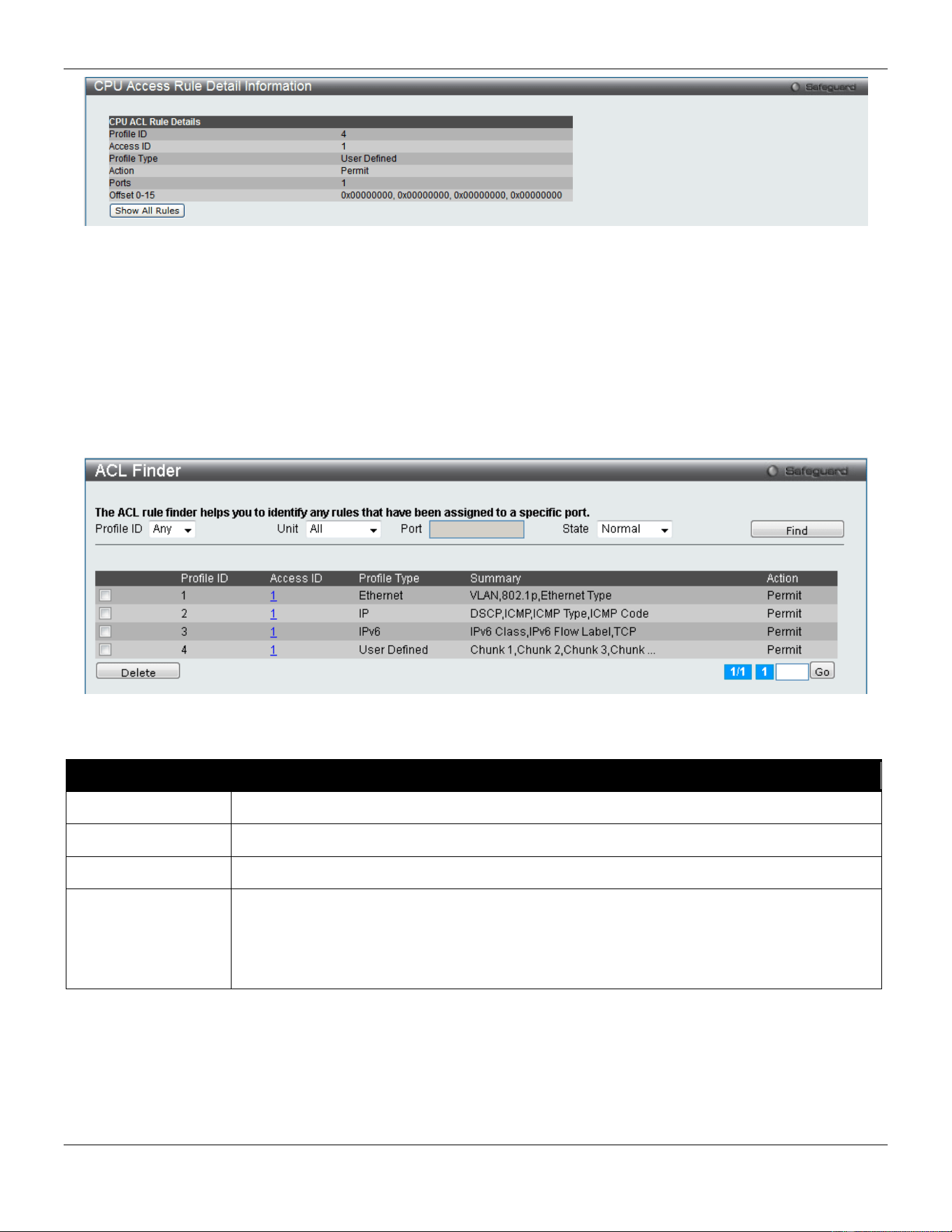
xStack® DGS-3420 Series Layer 2 Managed Stackable Gigabit Switch Web UI Reference Guide
257
Figure 7-43 CPU Access Rule Detail Information (Packet Content ACL)
Click the Show All Rules button to navigate back to the CPU Access Rule List.
ACL Finder
The ACL rule finder helps you to identify any rules that have been assigned to a specific port and edit existing rules
quickly.
To view this window, click ACL > ACL Finder as shown below:
Figure 7-44 ACL Finder window
The fields that can be configured are described below:
Parameter Description
Profile ID
Use the drop-down menu to select the Profile ID for the ACL rule finder to identify the rule.
Unit
Select the unit you wish to configure.
Port
Enter the port number for the ACL rule finder to identify the rule.
State
Use the drop-down menu to select the state.
Normal - Allow the user to find normal ACL rules.
CPU - Allow the user to find CPU ACL rules.
Egress – Allow the user to find Egress ACL rules.
Click the Find button to locate a specific entry based on the information entered.
Click the Delete button to remove the specific entry selected.
Enter a page number and click the Go button to navigate to a specific page when multiple pages exist.
ACL Flow Meter

xStack® DGS-3420 Series Layer 2 Managed Stackable Gigabit Switch Web UI Reference Guide
258
Before configuring the ACL Flow Meter, here is a list of acronyms and terms users will need to know.
• trTCM – Two Rate Three Color Marker. This, along with the srTCM, are two methods available on the switch
for metering and marking packet flow. The trTCM meters and IP flow and marks it as a color based on the
flow’s surpassing of two rates, the CIR and the PIR.
• CIR – Committed Information Rate. Common to both the trTCM and the srTCM, the CIR is measured in bytes
of IP packets. IP packet bytes are measured by taking the size of the IP header but not the link specific
headers. For the trTCM, the packet flow is marked green if it doesn’t exceed the CIR and yellow if it does. The
configured rate of the CIR must not exceed that of the PIR. The CIR can also be configured for unexpected
packet bursts using the CBS and PBS fields.
• CBS – Committed Burst Size. Measured in bytes, the CBS is associated with the CIR and is used to identify
packets that exceed the normal boundaries of packet size. The CBS should be configured to accept the
biggest IP packet that is expected in the IP flow.
• PIR – Peak Information Rate. This rate is measured in bytes of IP packets. IP packet bytes are measured by
taking the size of the IP header but not the link specific headers. If the packet flow exceeds the PIR, that
packet flow is marked red. The PIR must be configured to be equal or more than that of the CIR.
• PBS – Peak Burst Size. Measured in bytes, the PBS is associated with the PIR and is used to identify packets
that exceed the normal boundaries of packet size. The PBS should be configured to accept the biggest IP
packet that is expected in the IP flow.
• srTCM – Single Rate Three Color Marker. This, along with the trTCM, are two methods available on the switch
for metering and marking packet flow. The srTCM marks its IP packet flow based on the configured CBS and
EBS. A packet flow that does not reach the CBS is marked green, if it exceeds the CBS but not the EBS its
marked yellow, and if it exceeds the EBS its marked red.
• CBS – Committed Burst Size. Measured in bytes, the CBS is associated with the CIR and is used to identify
packets that exceed the normal boundaries of packet size. The CBS should be configured to accept the
biggest IP packet that is expected in the IP flow.
• EBS – Excess Burst Size. Measured in bytes, the EBS is associated with the CIR and is used to identify
packets that exceed the boundaries of the CBS packet size. The EBS is to be configured for an equal or larger
rate than the CBS.
• DSCP – Differentiated Services Code Point. The part of the packet header where the color will be added.
Users may change the DSCP field of incoming packets.
The ACL Flow Meter function will allow users to color code IP packet flows based on the rate of incoming packets.
Users have two types of Flow metering to choose from, trTCM and srTCM, as explained previously. When a packet
flow is placed in a color code, the user can choose what to do with packets that have exceeded that color-coded rate.
• Green – When an IP flow is in the green mode, its configurable parameters can be set in the Conform field,
where the packets can have their DSCP field changed. This is an acceptable flow rate for the ACL Flow Meter
function.
• Yellow – When an IP flow is in the yellow mode, its configurable parameters can be set in the Exceed field.
Users may choose to either Permit or Drop exceeded packets. Users may also choose to change the DSCP
field of the packets.
• Red – When an IP flow is in the red mode, its configurable parameters can be set in the Violate field. Users
may choose to either Permit or Drop exceeded packets. Users may also choose to change the DSCP field of
the packets.
Users may also choose to count exceeded packets by clicking the Counter check box. If the counter is enabled, the
counter setting in the access profile will be disabled. Users may only enable two counters for one flow meter at any
given time.
To view this window, click ACL > ACL Flow Meter, as shown below:
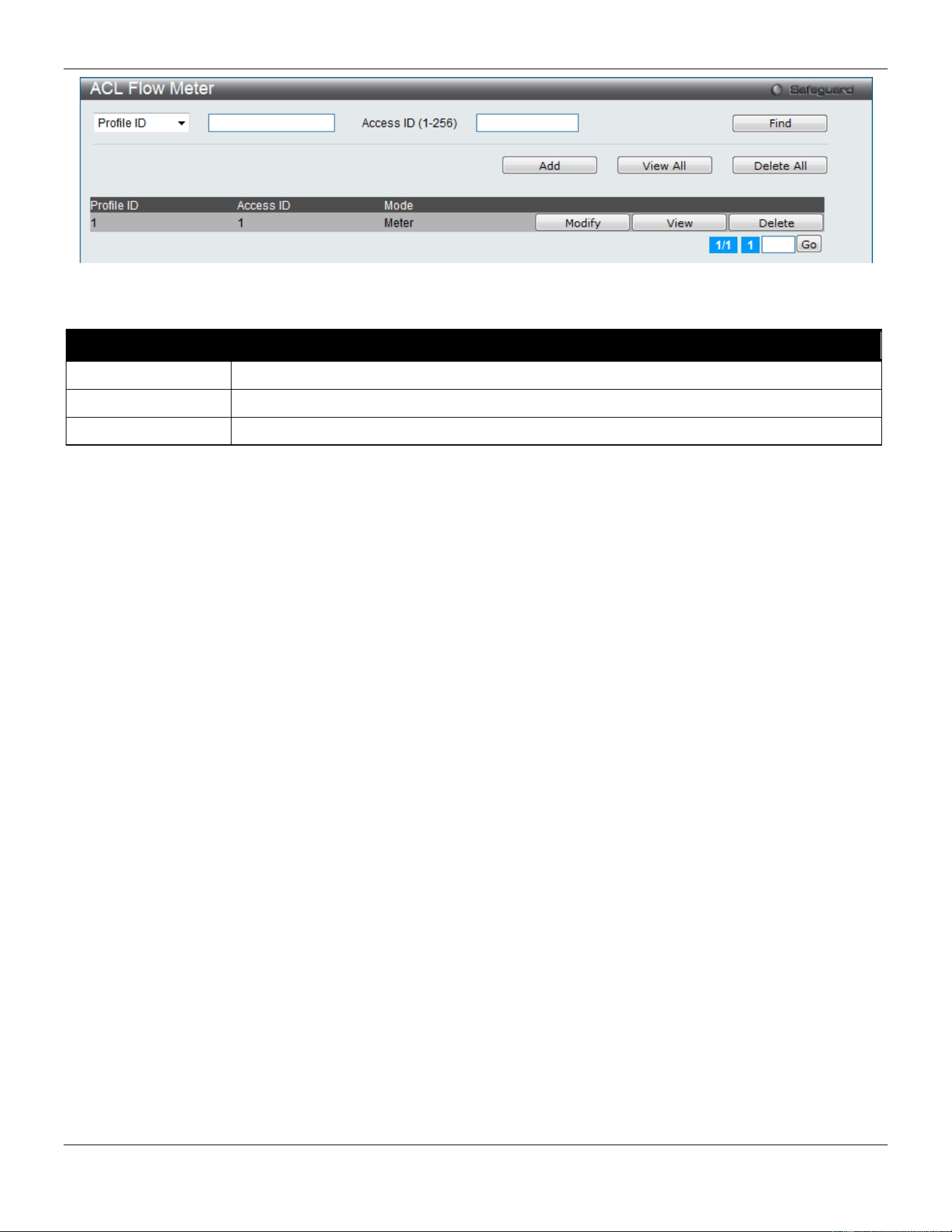
xStack® DGS-3420 Series Layer 2 Managed Stackable Gigabit Switch Web UI Reference Guide
259
Figure 7-45 ACL Flow Meter
The fields that can be configured are described below:
Parameter Description
Profile ID
Enter the Profile ID for the flow meter.
Profile Name
Enter the Profile Name for the flow meter.
Access ID (1-256)
Enter the Access ID for the flow meter.
Click the Find button to locate a specific entry based on the information entered.
Click the Add button to add a new entry based on the information entered.
Click the View All button to display all the existing entries.
Click the Delete All button to remove all the entries listed.
Click the Modify button to re-configure the specific entry.
Click the View button to display the information of the specific entry.
Click the Delete button to remove the specific entry.
After clicking the Add or Modify button, the following page will appear:
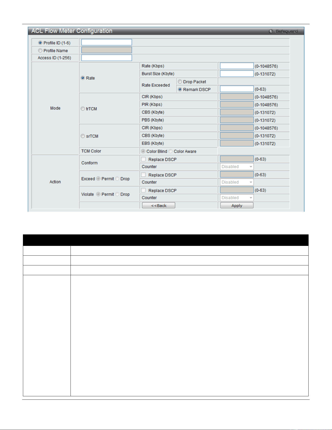
xStack® DGS-3420 Series Layer 2 Managed Stackable Gigabit Switch Web UI Reference Guide
260
Figure 7-46 ACL Flow meter Configuration window
The fields that can be configured are described below:
Parameter Description
Profile ID
Here the user can enter the Profile ID for the flow meter.
Profile Name
Here the user can enter the Profile Name for the flow meter.
Access ID
Here the user can enter the Access ID for the flow meter.
Mode Rate – Specify the rate for single rate two color mode.
Rate – Specify the committed bandwidth in Kbps for the flow.
Burst Size – Specify the burst size for the single rate two color mode. The unit is in kilobyte.
Rate Exceeded – Specify the action for packets that exceed the committed rate in single rate
two color mode. The action can be specified as one of the following:
Drop Packet – Drop the packet immediately.
Remark DSCP – Mark the packet with a specified DSCP. The packet is set to drop for packets
with a high precedence.
trTCM – Specify the “two-rate three-color mode.”
CIR – Specify the Committed information Rate. The unit is Kbps. CIR should always be equal or
less than PIR.
PIR – Specify the Peak information Rate. The unit is Kbps. PIR should always be equal to or
greater than CIR.
CBS – Specify the Committed Burst Size. The unit is in kilobyte.
PBS – Specify the Peak Burst Size. The unit is in kilobyte.
srTCM – Specify the “single-rate three-color mode”.
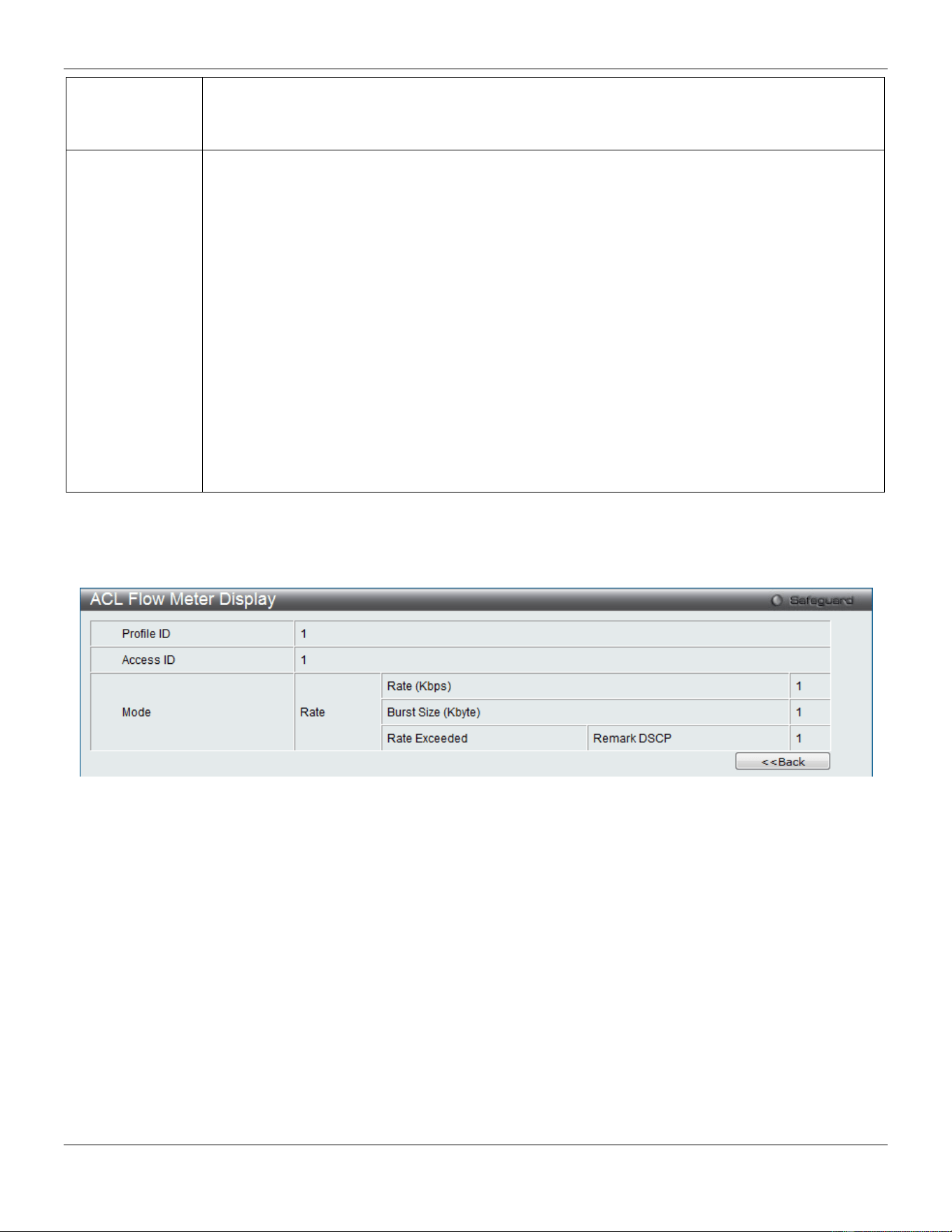
xStack® DGS-3420 Series Layer 2 Managed Stackable Gigabit Switch Web UI Reference Guide
261
CIR – Specify the Committed Information Rate. The unit is in kilobyte.
CBS – Specify the Committed Burst Size. The unit is in kilobyte.
EBS – Specify the Excess Burst Size. The unit is in kilobyte.
Action Conform – This field denotes the green packet flow. Green packet flows may have their DSCP
field rewritten to a value stated in this field. Users may also choose to count green packets by
using counter parameter.
Replace DSCP – Packets that are in the green flow may have their DSCP field rewritten using
this parameter and entering the DSCP value to replace.
Counter – Use this parameter to enable or disable the packet counter for the specified ACL entry
in the green flow.
Exceed – This field denotes the yellow packet flow. Yellow packet flows may have excess
packets permitted through or dropped. Users may replace the DSCP field of these packets by
checking its radio button and entering a new DSCP value in the allotted field.
Counter – Use this parameter to enable or disable the packet counter for the specified ACL entry
in the yellow flow.
Violate – This field denotes the red packet flow. Red packet flows may have excess packets
permitted through or dropped. Users may replace the DSCP field of these packets by checking
its radio button and entering a new DSCP value in the allotted field.
Counter – Use this parameter to enable or disable the packet counter for the specified ACL entry
in the red flow.
Click the <<Back button to discard the changes made and return to the previous page.
Click the Apply button to accept the changes made.
After clicking the View button, the following page will appear:
Figure 7-47 ACL Flow meter Display window
Click the <<Back button to return to the previous page.
Egress Access Profile List
Egress ACL performs per-flow processing of packets when they egress the Switch. The Switch supports three Profile
Types, Ethernet ACL, IPv4 ACL, and IPv6 ACL.
To view this window, click ACL > Egress Access Profile List as shown below:
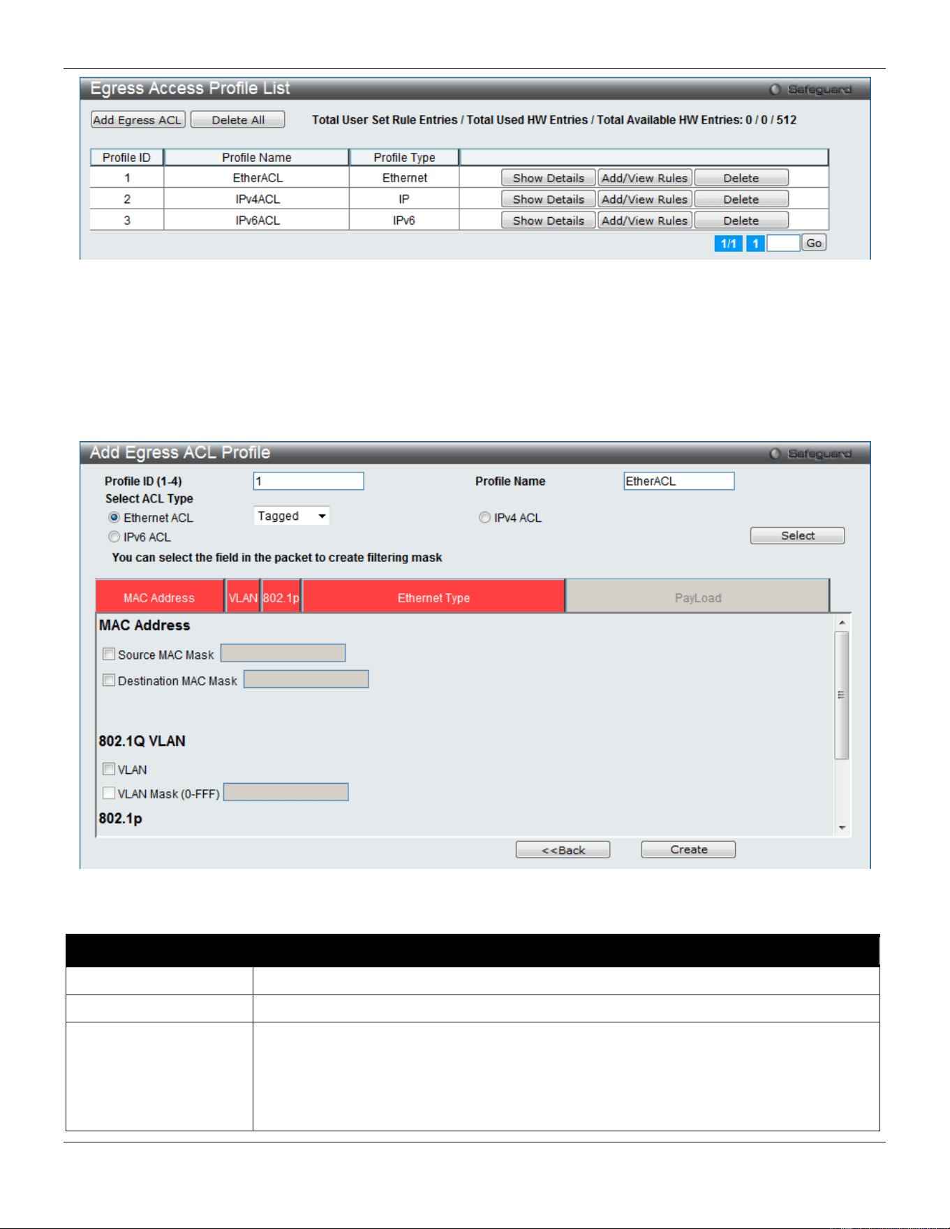
xStack® DGS-3420 Series Layer 2 Managed Stackable Gigabit Switch Web UI Reference Guide
262
Figure 7-48 Egress Access Profile List window
Adding an Ethernet ACL Profile
The window shown below is the Add Egress ACL Profile window for Ethernet. To use specific filtering masks in this
egress ACL profile, click the packet filtering mask field to highlight it red. This will add more filed to the mask.
After clicking the Add Egress ACL button, the following page will appear:
Figure 7-49 Add Egress ACL Profile window (Ethernet ACL)
The fields that can be configured are described below:
Parameter Description
Profile ID (1-4)
Enter a unique identifier number for this profile set. This value can be set from 1 to 4.
Profile Name
Enter a profile name for the profile created.
Select ACL Type
Select profile based on Ethernet (MAC Address), IPv4 address, or IPv6 address. This
will change the window according to the requirements for the type of profile.
Select Ethernet ACL to instruct the Switch to examine the layer 2 part of each packet
header.
Select IPv4 ACL to instruct the Switch to examine the IPv4 address in each frame's
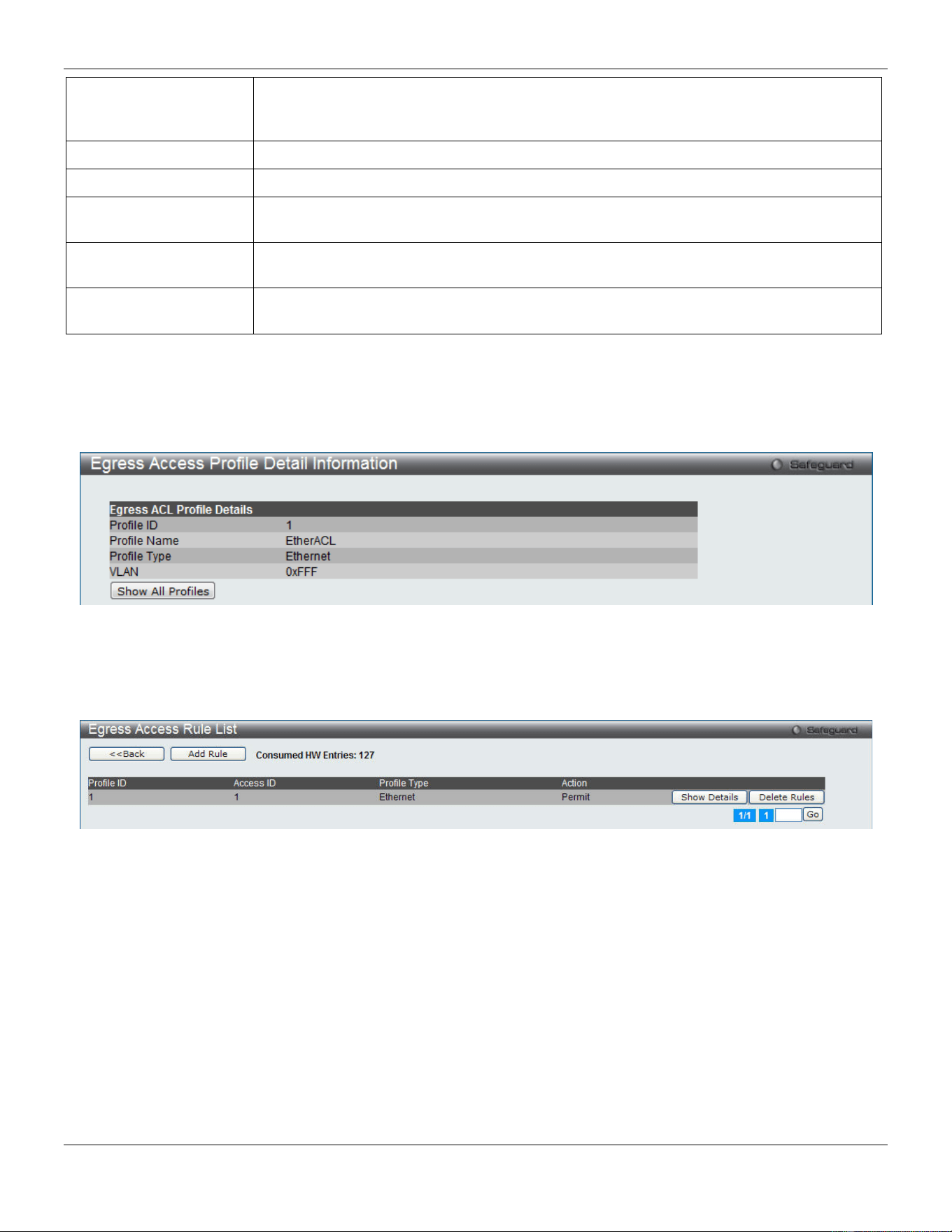
xStack® DGS-3420 Series Layer 2 Managed Stackable Gigabit Switch Web UI Reference Guide
263
header.
Select IPv6 ACL to instruct the Switch to examine the IPv6 address in each frame's
header.
Source MAC Mask
Enter a MAC address mask for the source MAC address.
Destination MAC Mask
Enter a MAC address mask for the destination MAC address.
802.1Q VLAN
Selecting this option instructs the Switch to examine the 802.1Q VLAN identifier of each
packet header and use this as the full or partial criterion for forwarding.
802.1p
Selecting this option instructs the Switch to examine the 802.1p priority value of each
packet header and use this as the, or part of the criterion for forwarding.
Ethernet Type
Selecting this option instructs the Switch to examine the Ethernet type value in each
frame's header.
Click the Select button to select an ACL type.
Click the <<Back button to discard the changes made and return to the previous page.
Click the Create button to create a profile.
After clicking the Show Details button, the following page will appear:
Figure 7-50 Egress Access Profile Detail Information window (Ethernet ACL)
Click the Show All Profiles button to navigate back to the Egress Access Profile List window.
After clicking the Add/View Rules button, the following page will appear:
Figure 7-51 Egress Access Rule List window (Ethernet ACL)
Click the <<Back button to return to the previous page.
Click the Add Rule button to create a new ACL rule in this profile.
Click the Show Details button to view more information about the specific rule created.
Click the Delete Rules button to remove the specific entry.
Enter a page number and click the Go button to navigate to a specific page when multiple pages exist.
After clicking the Add Rule button, the following page will appear:
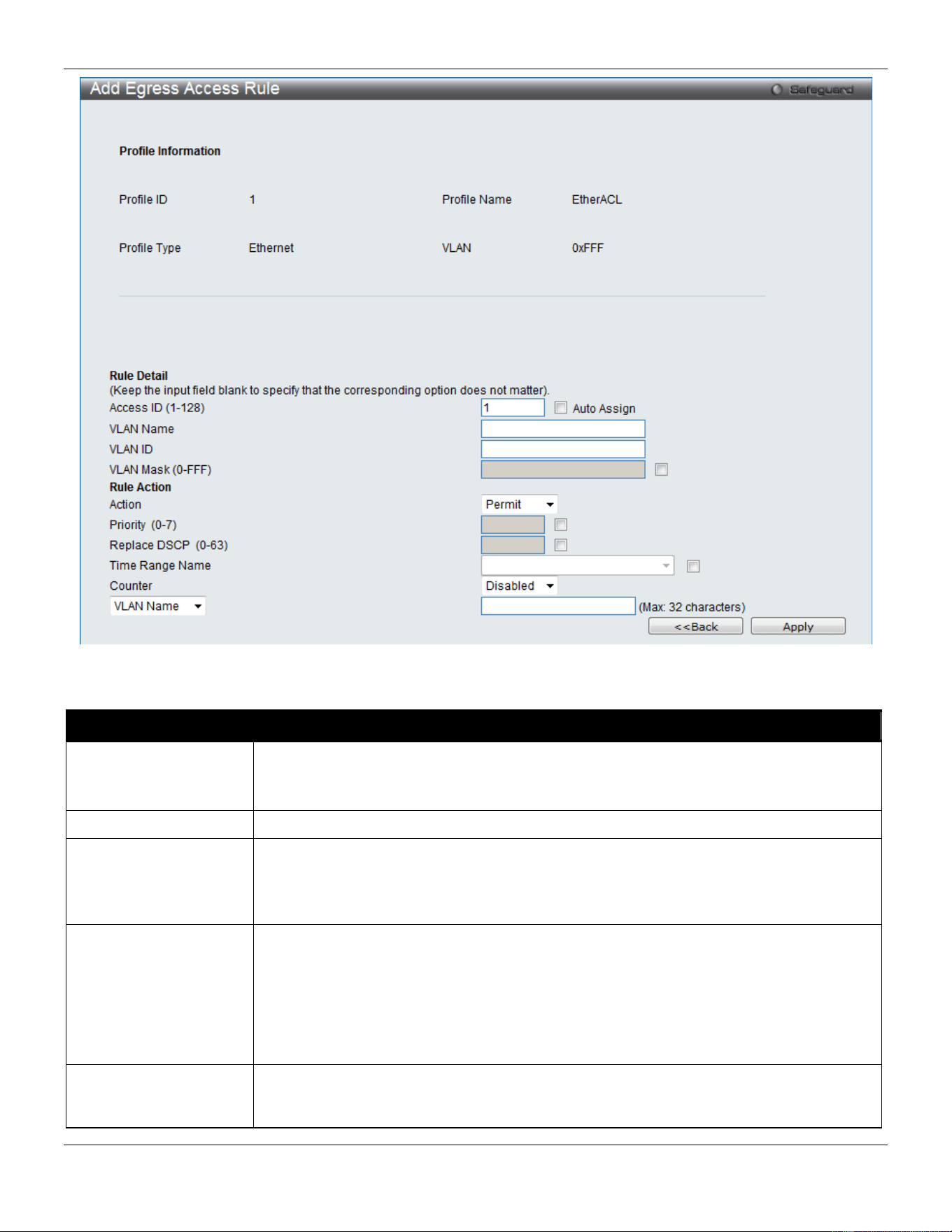
xStack® DGS-3420 Series Layer 2 Managed Stackable Gigabit Switch Web UI Reference Guide
264
Figure 7-52 Add Egress Access Rule window (Ethernet ACL)
The fields that can be configured are described below:
Parameter Description
Access ID (1-128)
Type in a unique identifier number for this access. This value can be set from 1 to 128.
Auto Assign – Tick the check box will instruct the Switch to automatically assign an
Access ID for the rule being created.
Ethernet Type
Specify the Ethernet type.
Action Select Permit to specify that the packets that match the access profile are forwarded by
the Switch, according to any additional rule added (see below).
Select Deny to specify that the packets that match the access profile are not forwarded
by the Switch and will be filtered.
Priority (0-7)
Tick the corresponding check box if you want to re-write the 802.1p default priority of a
packet to the value entered in the Priority field, which meets the criteria specified
previously in this command, before forwarding it on to the specified CoS queue.
Otherwise, a packet will have its incoming 802.1p user priority re-written to its original
value before being forwarded by the Switch.
For more information on priority queues, CoS queues and mapping for 802.1p, see the
QoS section of this manual.
Replace DSCP (0-63)
Select this option to instruct the Switch to replace the DSCP value (in a packet that
meets the selected criteria) with the value entered in the adjacent field. When an ACL
rule is added to change both the priority and DSCP of an IPv4 packet, only one of them

xStack® DGS-3420 Series Layer 2 Managed Stackable Gigabit Switch Web UI Reference Guide
265
can be modified due to a chip limitation. Currently the priority is changed when both the
priority and DSCP are set to be modified.
Time Range Name
Tick the check box and enter the name of the Time Range settings that has been
previously configured in the Time Range Settings window. This will set specific times
when this access rule will be implemented on the Switch.
Counter
Here the user can select the counter. By checking the counter, the administrator can see
how many times that the rule was hit.
Port
When a range of ports is to be configured, the Auto Assign check box MUST be ticked in
the Access ID field of this window. If not, the user will be presented with an error
message and the access rule will not be configured.
Port Group ID
Specify the port group ID to apply to the access rule.
Port Group Name
Specify the port group name to apply to the access rule.
VLAN Name
Specify the VLAN name to apply to the access rule.
VLAN ID
Specify the VLAN ID to apply to the access rule.
Click the <<Back button to discard the changes made and return to the previous page.
Click the Apply button to accept the changes made.
After clicking the Show Details button in the Egress Access Rule List, the following page will appear:
Figure 7-53 Egress Access Rule Detail Information window (Ethernet ACL)
Click the Show All Rules button to navigate back to the Access Rule List.
Adding an IPv4 Egress ACL Profile
The window shown below is the Add Egress ACL Profile window for IPv4. To use specific filtering masks in this egress
ACL profile, click the packet filtering mask field to highlight it red. This will add more filed to the mask.
After clicking the Add Egress ACL button, the following page will appear:
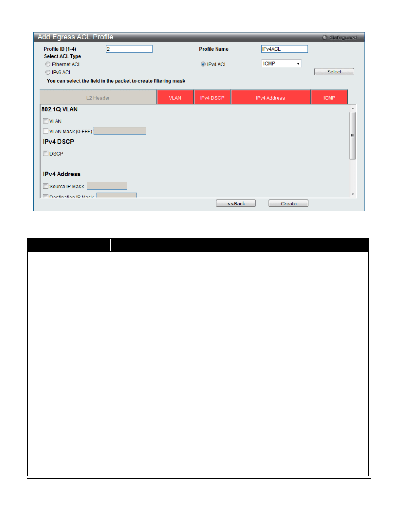
xStack® DGS-3420 Series Layer 2 Managed Stackable Gigabit Switch Web UI Reference Guide
266
Figure 7-54 Add Egress ACL Profile window (IPv4 ACL)
The fields that can be configured are described below:
Parameter Description
Profile ID (1-4)
Enter a unique identifier number for this profile set. This value can be set from 1 to 4.
Profile Name
Enter a profile name for the profile created.
Select ACL Type
Select profile based on Ethernet (MAC Address), IPv4 address, or IPv6 address. This
will change the window according to the requirements for the type of profile.
Select Ethernet ACL to instruct the Switch to examine the layer 2 part of each packet
header.
Select IPv4 ACL to instruct the Switch to examine the IPv4 address in each frame's
header.
Select IPv6 ACL to instruct the Switch to examine the IPv6 address in each frame's
header.
802.1Q VLAN
Selecting this option instructs the Switch to examine the 802.1Q VLAN identifier of
each packet header and use this as the full or partial criterion for forwarding.
IPv4 DSCP
Selecting this option instructs the Switch to examine the DiffServ Code part of each
packet header and use this as the, or part of the criterion for forwarding.
IPv4 Source IP Mask
Enter an IP address mask for the source IP address.
IPv4 Destination IP
Mask
Enter an IP address mask for the destination IP address.
Protocol
Selecting this option instructs the Switch to examine the protocol type value in each
frame's header. Then the user must specify what protocol(s) to include according to the
following guidelines:
Select ICMP to instruct the Switch to examine the Internet Control Message Protocol
(ICMP) field in each frame's header.
Select Type to further specify that the access profile will apply an ICMP type value, or
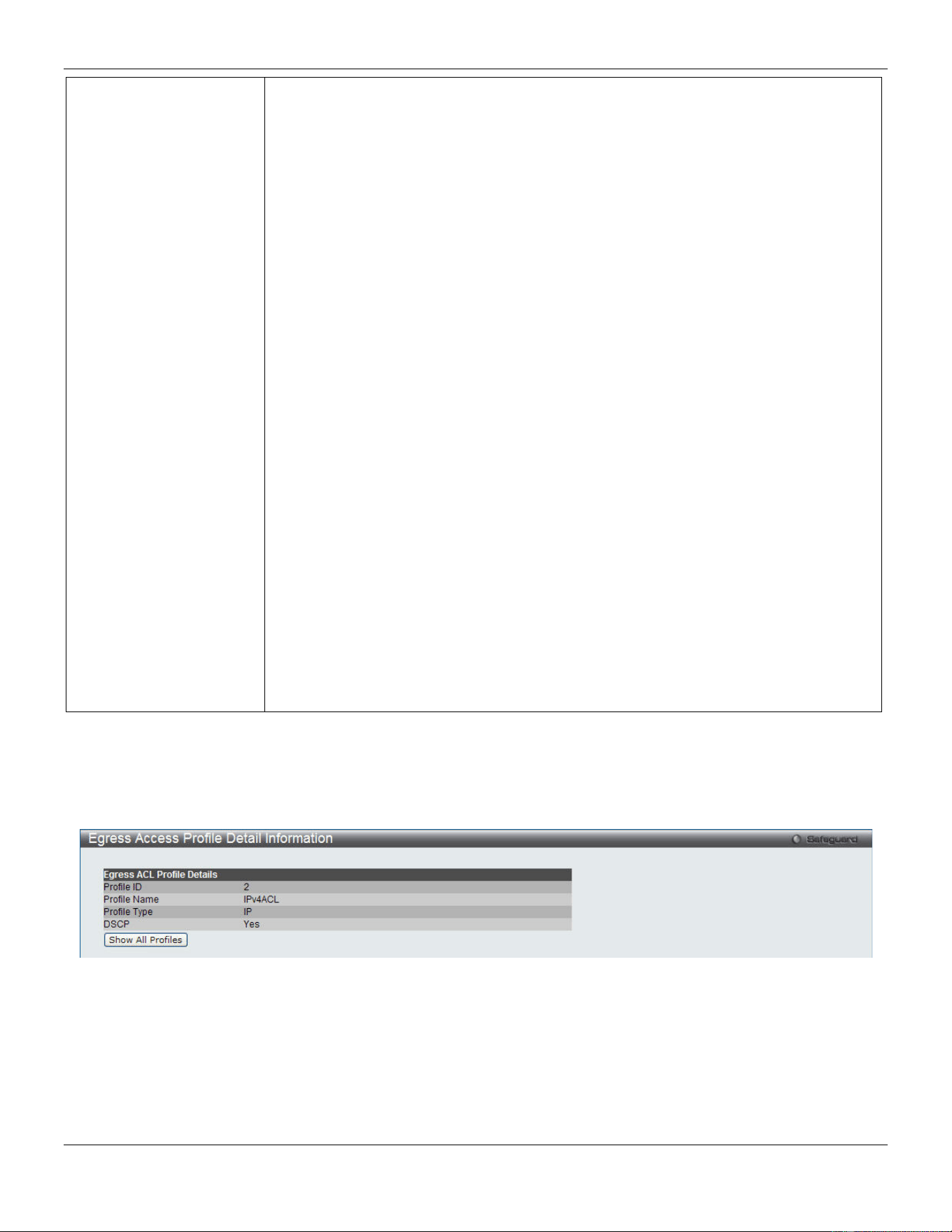
xStack® DGS-3420 Series Layer 2 Managed Stackable Gigabit Switch Web UI Reference Guide
267
specify Code to further specify that the access profile will apply an ICMP code value.
Select IGMP to instruct the Switch to examine the Internet Group Management
Protocol (IGMP) field in each frame's header.
Select Type to further specify that the access profile will apply an IGMP type value.
Select TCP to use the TCP port number contained in an incoming packet as the
forwarding criterion. Selecting TCP requires that you specify a source port mask and/or
a destination port mask.
src port mask - Specify a TCP port mask for the source port in hex form (hex 0x0-
0xffff), which you wish to filter.
dst port mask - Specify a TCP port mask for the destination port in hex form (hex 0x0-
0xffff) which you wish to filter.
flag bit - The user may also identify which flag bits to filter. Flag bits are parts of a
packet that determine what to do with the packet. The user may filter packets by
filtering certain flag bits within the packets, by checking the boxes corresponding to the
flag bits of the TCP field. The user may choose between urg (urgent), ack
(acknowledgement), psh (push), rst (reset), syn (synchronize), fin (finish).
Select UDP to use the UDP port number contained in an incoming packet as the
forwarding criterion. Selecting UDP requires that you specify a source port mask
and/or a destination port mask.
src port mask - Specify a UDP port mask for the source port in hex form (hex 0x0-
0xffff).
dst port mask - Specify a UDP port mask for the destination port in hex form (hex 0x0-
0xffff).
Select Protocol ID - Enter a value defining the protocol ID in the packet header to
mask. Specify the protocol ID mask in hex form (hex 0x0-0xff.
Protocol ID Mask - Specify that the rule applies to the IP protocol ID traffic.
User Define - Specify the Layer 4 part mask
Click the Select button to select an ACL type.
Click the <<Back button to discard the changes made and return to the previous page.
Click the Create button to create a profile.
After clicking the Show Details button, the following page will appear:
Figure 7-55 Egress Access Profile Detail Information window (IPv4 ACL)
Click the Show All Profiles button to navigate back to the Egress Access Profile List window.
After clicking the Add/View Rules button, the following page will appear:
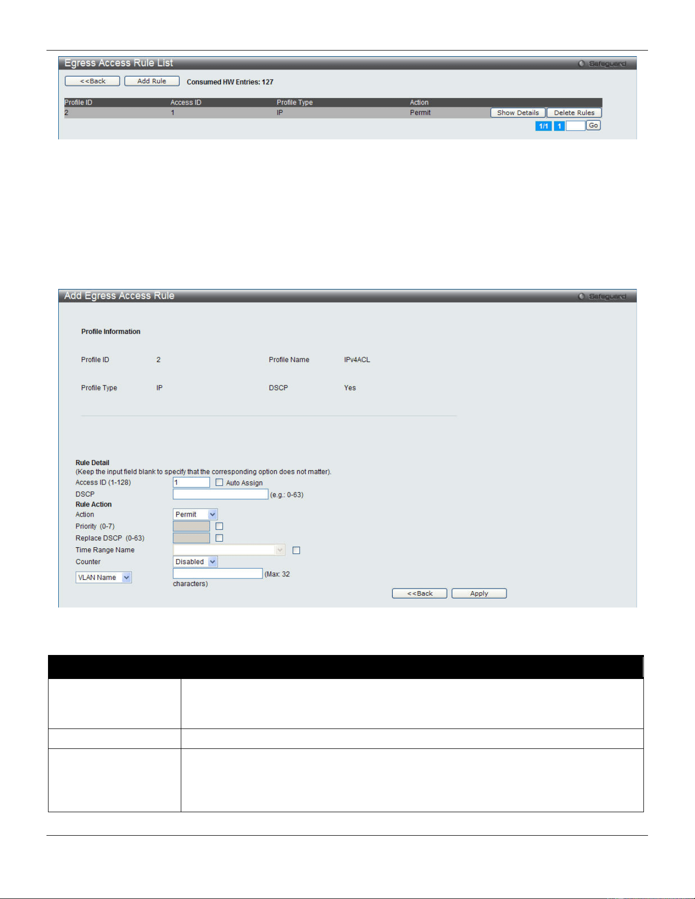
xStack® DGS-3420 Series Layer 2 Managed Stackable Gigabit Switch Web UI Reference Guide
268
Figure 7-56 Egress Access Rule List window (IPv4 ACL)
Click the <<Back button to return to the previous page.
Click the Add Rule button to create a new ACL rule in this profile.
Click the Show Details button to view more information about the specific rule created.
Click the Delete Rules button to remove the specific entry.
Enter a page number and click the Go button to navigate to a specific page when multiple pages exist.
After clicking the Add Rule button, the following page will appear:
Figure 7-57 Add Egress Access Rule (IPv4 ACL)
The fields that can be configured are described below:
Parameter Description
Access ID (1-128)
Type in a unique identifier number for this access. This value can be set from 1 to 128.
Auto Assign – Tick the check box will instruct the Switch to automatically assign an
Access ID for the rule being created.
DSCP
Specify the value of DSCP. The DSCP value ranges from 0 to 63.
Action
Select Permit to specify that the packets that match the access profile are forwarded by
the Switch, according to any additional rule added (see below).
Select Deny to specify that the packets that match the access profile are not forwarded
by the Switch and will be filtered.
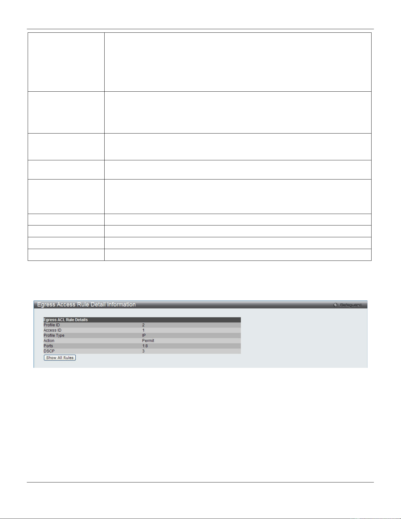
xStack® DGS-3420 Series Layer 2 Managed Stackable Gigabit Switch Web UI Reference Guide
269
Priority (0-7)
Tick the corresponding check box if you want to re-write the 802.1p default priority of a
packet to the value entered in the Priority field, which meets the criteria specified
previously in this command, before forwarding it on to the specified CoS queue.
Otherwise, a packet will have its incoming 802.1p user priority re-written to its original
value before being forwarded by the Switch.
For more information on priority queues, CoS queues and mapping for 802.1p, see the
QoS section of this manual.
Replace DSCP (0-63)
Select this option to instruct the Switch to replace the DSCP value (in a packet that meets
the selected criteria) with the value entered in the adjacent field. When an ACL rule is
added to change both the priority and DSCP of an IPv4 packet, only one of them can be
modified due to a chip limitation. Currently the priority is changed when both the priority
and DSCP are set to be modified.
Time Range Name
Tick the check box and enter the name of the Time Range settings that has been
previously configured in the Time Range Settings window. This will set specific times
when this access rule will be implemented on the Switch.
Counter
Here the user can select the counter. By checking the counter, the administrator can see
how many times that the rule was hit.
Ports
When a range of ports is to be configured, the Auto Assign check box MUST be ticked in
the Access ID field of this window. If not, the user will be presented with an error
message and the access rule will not be configured. Ticking the All Ports check box will
denote all ports on the Switch.
Port Group ID
Specify the port group ID to apply to the access rule.
Port Group Name
Specify the port group name to apply to the access rule.
VLAN Name
Specify the VLAN name to apply to the access rule.
VLAN ID
Specify the VLAN ID to apply to the access rule.
Click the <<Back button to discard the changes made and return to the previous page.
Click the Apply button to accept the changes made.
After clicking the Show Details button in the Egress Access Rule List, the following page will appear:
Figure 7-58 Egress Access Rule Detail Information (IPv4 ACL)
Click the Show All Rules button to navigate back to the Access Rule List.
Adding an IPv6 Egress ACL Profile
The window shown below is the Add Egress ACL Profile window for IPv6. To use specific filtering masks in this egress
ACL profile, click the packet filtering mask field to highlight it red. This will add more filed to the mask.
After clicking the Add Egress ACL button, the following page will appear:
xStack® DGS-3420 Series Layer 2 Managed Stackable Gigabit Switch Web UI Reference Guide
270
Figure 7-59 Add Egress ACL Profile window (IPv6 ACL)
The fields that can be configured are described below:
Parameter Description
Profile ID (1-4) Enter a unique identifier number for this profile set. This value can be set from 1 to 4.
Profile Name
Enter a profile name for the profile created.
Select ACL Type
Select profile based on Ethernet (MAC Address), IPv4 address, or IPv6 address. This
will change the window according to the requirements for the type of profile.
Select Ethernet ACL to instruct the Switch to examine the layer 2 part of each packet
header.
Select IPv4 ACL to instruct the Switch to examine the IPv4 address in each frame's
header.
Select IPv6 ACL to instruct the Switch to examine the IPv6 address in each frame's
header.
IPv6 Class Ticking this check box will instruct the Switch to examine the class field of the IPv6
header. This class field is a part of the packet header that is similar to the Type of
Service (ToS) or Precedence bits field in IPv4.
IPv6 TCP Source Port Mask – Specify that the rule applies to the range of TCP source ports.
Destination Port Mask – Specify the range of the TCP destination port range.
IPv6 UDP Source Port Mask – Specify the range of the UDP source port range.
Destination Port Mask – Specify the range of the UDP destination port mask.
ICMP Select ICMP to instruct the Switch to examine the Internet Control Message Protocol
(ICMP) field in each frame's header.
IPv6 Source Mask
The user may specify an IPv6 address mask for the source IPv6 address by ticking
the corresponding check box and entering the IPv6 address mask, e.g.
FFFF:FFFF::FFFF.
xStack® DGS-3420 Series Layer 2 Managed Stackable Gigabit Switch Web UI Reference Guide
271
IPv6 Destination Mask
The user may specify an IPv6 address mask for the destination IPv6 address by
ticking the corresponding check box and entering the IPv6 address mask, e.g.
FFFF:FFFF::FFFF.
Click the Select button to select an ACL type.
Click the <<Back button to discard the changes made and return to the previous page.
Click the Create button to create a profile.
After clicking the Show Details button, the following page will appear:
Figure 7-60 Egress Access Profile Detail Information window (IPv6 ACL)
Click the Show All Profiles button to navigate back to the Egress Access Profile List window.
After clicking the Add/View Rules button, the following page will appear:
Figure 7-61 Egress Access Rule List window (IPv6 ACL)
Click the <<Back button to return to the previous page.
Click the Add Rule button to create a new ACL rule in this profile.
Click the Show Details button to view more information about the specific rule created.
Click the Delete Rules button to remove the specific entry.
Enter a page number and click the Go button to navigate to a specific page when multiple pages exist.
After clicking the Add Rule button, the following page will appear:
xStack® DGS-3420 Series Layer 2 Managed Stackable Gigabit Switch Web UI Reference Guide
272
Figure 7-62 Add Egress Access Rule (IPv6 ACL)
The fields that can be configured are described below:
Parameter Description
Access ID (1-128)
Type in a unique identifier number for this access. This value can be set from 1 to 128.
Auto Assign – Tick the check box will instruct the Switch to automatically assign an
Access ID for the rule being created.
Class
Specify the value of IPv6 class.
Action Select Permit to specify that the packets that match the access profile are forwarded by
the Switch, according to any additional rule added (see below).
Select Deny to specify that packets that match the access profile are not forwarded by
the Switch and will be filtered.
Priority (0-7)
Tick the corresponding check box to re-write the 802.1p default priority of a packet to the
value entered in the Priority field, which meets the criteria specified previously in this
command, before forwarding it on to the specified CoS queue. Otherwise, a packet will
have its incoming 802.1p user priority re-written to its original value before being
forwarded by the Switch.
For more information on priority queues, CoS queues and mapping for 802.1p, see the
QoS section of this manual.
Replace DSCP (0-63)
Select this option to instruct the Switch to replace the DSCP value (in a packet that meets
the selected criteria) with the value entered in the adjacent field. When an ACL rule is
added to change both the priority and DSCP of an IPv6 packet, only one of them can be
modified due to a chip limitation. Currently the priority is changed when both the priority
and DSCP are set to be modified.
Time Range Name
Tick the check box and enter the name of the Time Range settings that has been
previously configured in the Time Range Settings window. This will set specific times
when this access rule will be implemented on the Switch.
Counter
Here the user can select the counter. By checking the counter, the administrator can see
xStack® DGS-3420 Series Layer 2 Managed Stackable Gigabit Switch Web UI Reference Guide
273
how many times that the rule was hit.
Ports
When a range of ports is to be configured, the Auto Assign check box MUST be ticked in
the Access ID field of this window. If not, the user will be presented with an error
message and the access rule will not be configured. Ticking the All Ports check box will
denote all ports on the Switch.
Port Group ID
Specify the port group ID to apply to the access rule.
Port Group Name
Specify the port group name to apply to the access rule.
VLAN Name
Specify the VLAN name to apply to the access rule.
VLAN ID
Specify the VLAN ID to apply to the access rule.
Click the <<Back button to discard the changes made and return to the previous page.
Click the Apply button to accept the changes made.
After clicking the Show Details button in the Egress Access Rule List, the following page will appear:
Figure 7-63 Egress Access Rule Detail Information (IPv6 ACL)
Click the Show All Rules button to navigate back to the Access Rule List.
Egress ACL Flow Meter
This window is used to configure the packet flow-based metering based on an egress access profile and rule.
To view this window, click ACL > Egress ACL Flow Meter as shown below:
Figure 7-64 Egress ACL Flow Meter window
The fields that can be configured are described below:
Parameter Description
Profile ID
Here the user can enter the Profile ID for the flow meter.
Profile Name
Here the user can enter the Profile Name for the flow meter.
Access ID (1-128)
Here the user can enter the Access ID for the flow meter.
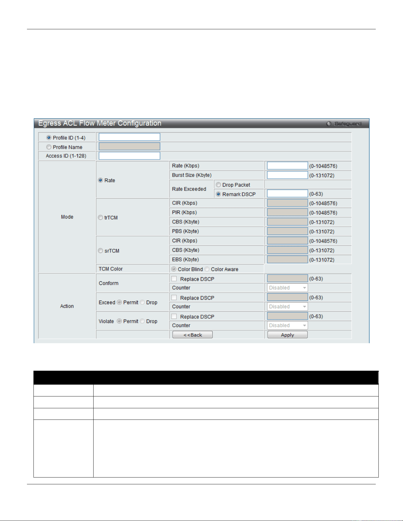
xStack® DGS-3420 Series Layer 2 Managed Stackable Gigabit Switch Web UI Reference Guide
274
Click the Find button to locate a specific entry based on the information entered.
Click the Add button to add a new entry based on the information entered.
Click the View All button to display all the existing entries.
Click the Delete All button to remove all the entries listed.
Click the Modify button to re-configure the specific entry.
Click the View button to display the information of the specific entry.
Click the Delete button to remove the specific entry.
After clicking the Add or Modify button, the following page will appear:
Figure 7-65 Egress ACL Flow Meter Configuration window
The fields that can be configured are described below:
Parameter Description
Profile ID
Enter the Profile ID for the flow meter.
Profile Name
Enter the Profile Name for the flow meter.
Access ID
Enter the Access ID for the flow meter.
Mode Rate – Specify the rate for single rate two color mode.
Rate – Specify the committed bandwidth in Kbps for the flow.
Burst Size – Specify the burst size for the single rate two color mode. The unit is in kilobyte.
Rate Exceeded – Specify the action for packets that exceed the committed rate in single rate
two color mode. The action can be specified as one of the following:
Drop Packet – Drop the packet immediately.
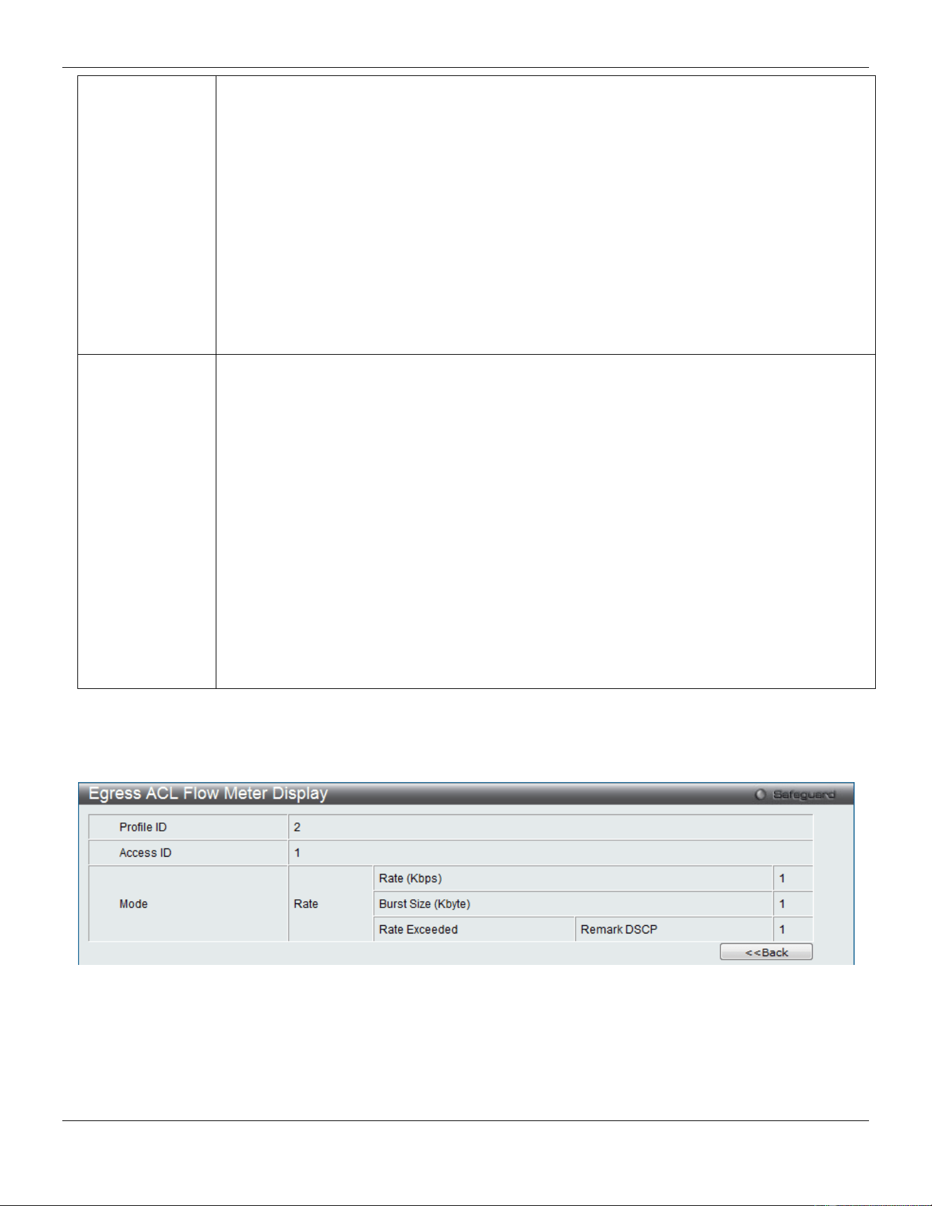
xStack® DGS-3420 Series Layer 2 Managed Stackable Gigabit Switch Web UI Reference Guide
275
Remark DSCP – Mark the packet with a specified DSCP. The packet is set to drop for packets
with a high precedence.
trTCM – Specify the “two-rate three-color mode.”
CIR – Specify the Committed information Rate. The unit is Kbps. CIR should always be equal
or less than PIR.
PIR – Specify the Peak information Rate. The unit is Kbps. PIR should always be equal to or
greater than CIR.
CBS – Specify the Committed Burst Size. The unit is in kilobyte.
PBS – Specify the Peak Burst Size. The unit is in kilobyte.
srTCM – Specify the “single-rate three-color mode”.
CIR – Specify the Committed Information Rate. The unit is in kilobyte.
CBS – Specify the Committed Burst Size. The unit is in kilobyte.
EBS – Specify the Excess Burst Size. The unit is in kilobyte.
Action Conform – This field denotes the green packet flow. Green packet flows may have their DSCP
field rewritten to a value stated in this field. Users may also choose to count green packets by
using counter parameter.
Replace DSCP – Packets that are in the green flow may have their DSCP field rewritten using
this parameter and entering the DSCP value to replace.
Counter – Use this parameter to enable or disable the packet counter for the specified ACL
entry in the green flow.
Exceed – This field denotes the yellow packet flow. Yellow packet flows may have excess
packets permitted through or dropped. Users may replace the DSCP field of these packets by
checking its radio button and entering a new DSCP value in the allotted field.
Counter – Use this parameter to enable or disable the packet counter for the specified ACL
entry in the yellow flow.
Violate – This field denotes the red packet flow. Red packet flows may have excess packets
permitted through or dropped. Users may replace the DSCP field of these packets by checking
its radio button and entering a new DSCP value in the allotted field.
Counter – Use this parameter to enable or disable the packet counter for the specified ACL
entry in the red flow.
Click the <<Back button to discard the changes made and return to the previous page.
Click the Apply button to accept the changes made.
After clicking the View button, the following page will appear:
Figure 7-66 Egress ACL Flow meter Display window
Click the <<Back button to return to the previous page.
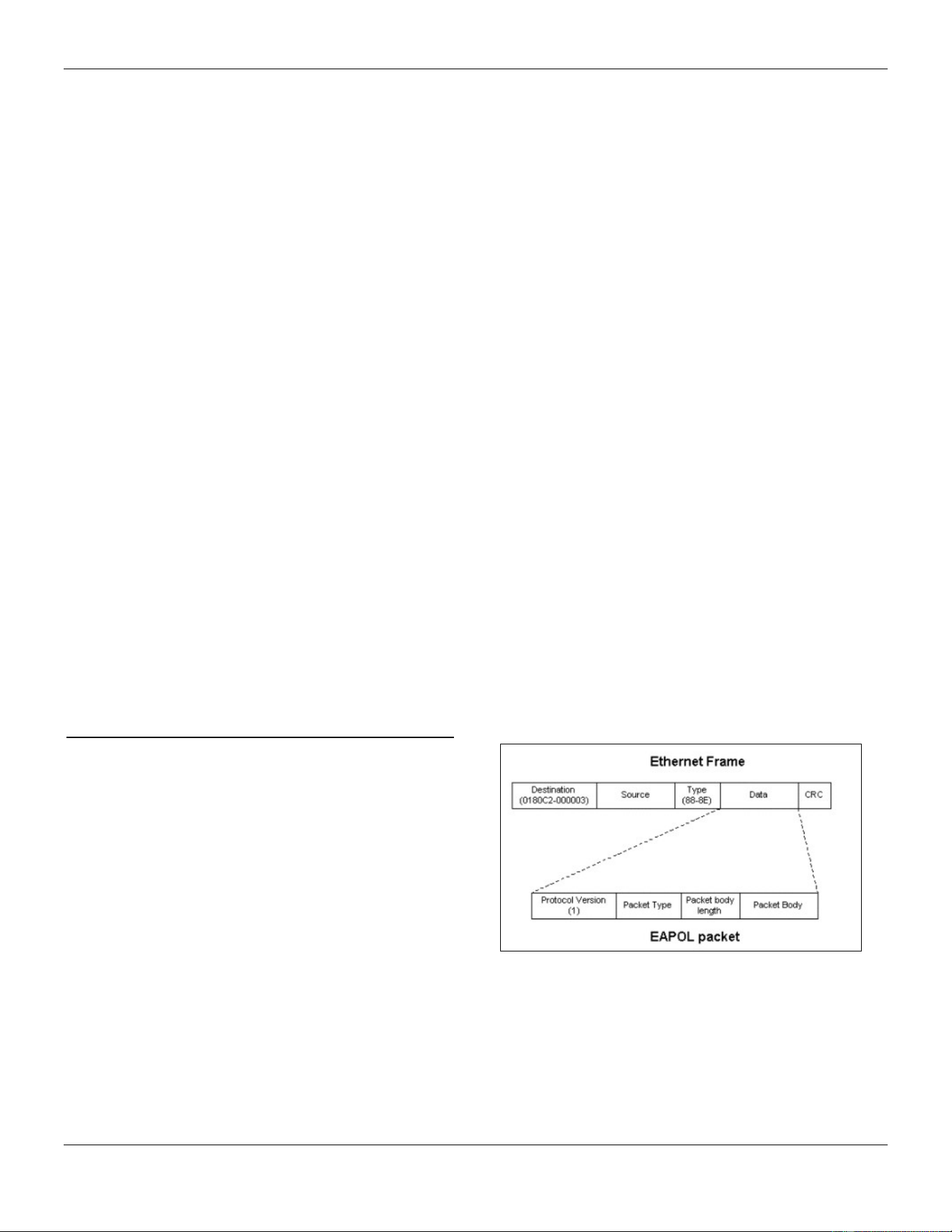
xStack® DGS-3420 Series Layer 2 Managed Stackable Gigabit Switch Web UI Reference Guide
276
Chapter 8 Security
802.1X
RADIUS
IP-MAC-Port Binding (IMPB)
MAC-based Access Control (MAC)
Web-based Access Control (WAC)
Japanese Web-based Access Control (JWAC)
Compound Authentication
IGMP Access Control Settings
Port Security
ARP Spoofing Prevention Settings
BPDU Attack Protection
Loopback Detection Settings
NetBIOS Filtering Settings
Traffic Segmentation Settings
DHCP Server Screening
Access Authentication Control
SSL Settings
SSH
DoS Attack Prevention Settings
Trusted Host Settings
Safeguard Engine Settings
SFTP Server Settings
802.1X
802.1X (Port-Based and Host-Based Access Control)
The IEEE 802.1X standard is a security measure for
authorizing and authenticating users to gain access to
various wired or wireless devices on a specified Local
Area Network by using a Client and Server based access
control model. This is accomplished by using a RADIUS
server to authenticate users trying to access a network by
relaying Extensible Authentication Protocol over LAN
(EAPOL) packets between the Client and the Server. The
following figure represents a basic EAPOL packet:
Figure 8-1 The EAPOL Packet

xStack® DGS-3420 Series Layer 2 Managed Stackable Gigabit Switch Web UI Reference Guide
277
Utilizing this method, unauthorized devices are restricted
from connecting to a LAN through a port to which the user
is connected. EAPOL packets are the only traffic that can
be transmitted through the specific port until authorization
is granted. The 802.1X access control method has three
roles, each of which are vital to creating and up keeping a
stable and working Access Control security method.
Figure 8-2 The three roles of 802.1X
The following section will explain the three roles of Client, Authenticator and Authentication Server in greater detail.
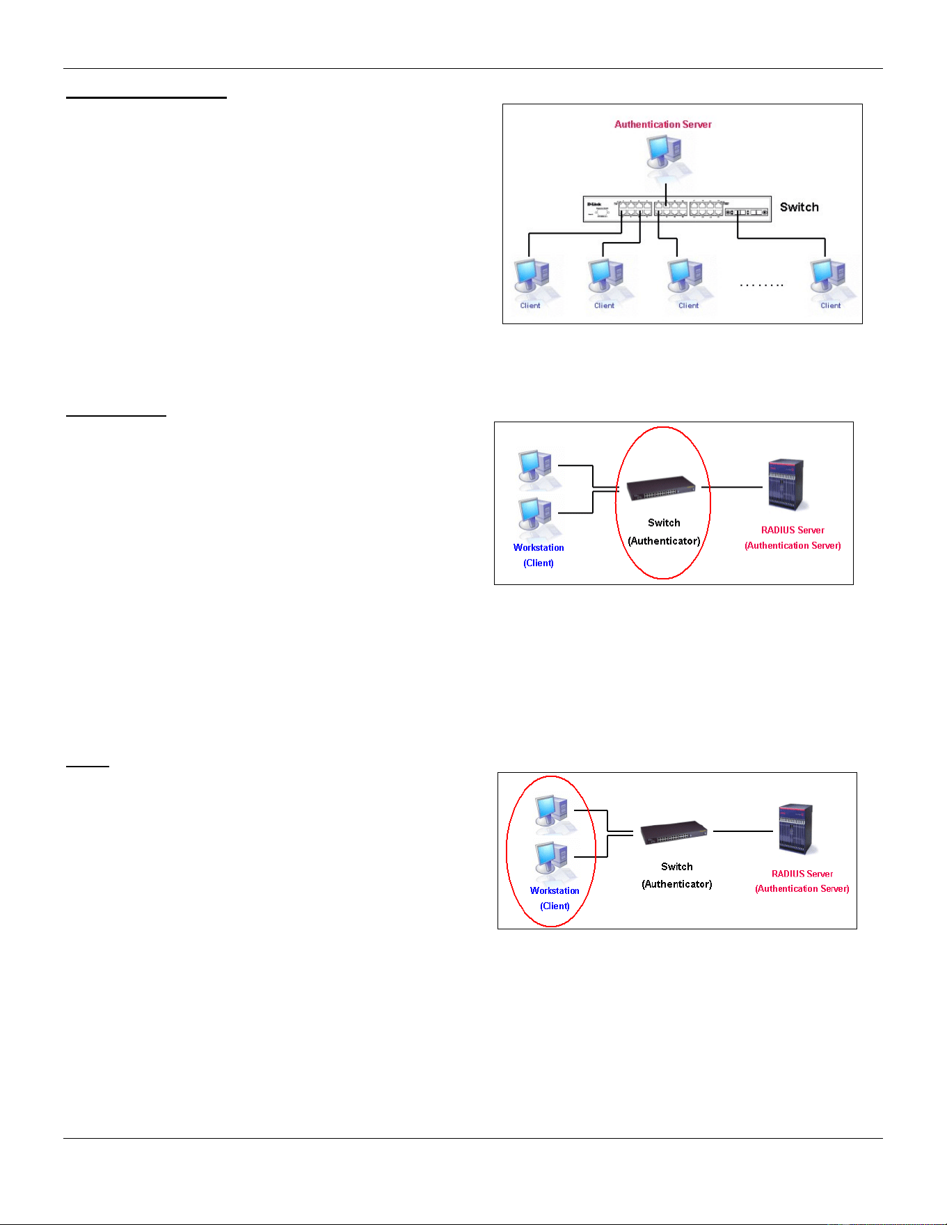
xStack® DGS-3420 Series Layer 2 Managed Stackable Gigabit Switch Web UI Reference Guide
278
Authentication Server
The Authentication Server is a remote device that is
connected to the same network as the Client and
Authenticator, must be running a RADIUS Server program
and must be configured properly on the Authenticator
(Switch). Clients connected to a port on the Switch must be
authenticated by the Authentication Server (RADIUS)
before attaining any services offered by the Switch on the
LAN. The role of the Authentication Server is to certify the
identity of the Client attempting to access the network by
exchanging secure information between the RADIUS
server and the Client through EAPOL packets and, in turn,
informs the Switch whether or not the Client is granted
access to the LAN and/or switches services.
Figure 8-3 The Authentication Server
Authenticator
The Authenticator (the Switch) is an intermediary between
the Authentication Server and the Client. The
Authenticator serves two purposes when utilizing the
802.1X function. The first purpose is to request
certification information from the Client through EAPOL
packets, which is the only information allowed to pass
through the Authenticator before access is granted to the
Client. The second purpose of the Authenticator is to
verify the information gathered from the Client with the
Authentication Server, and to then relay that information
back to the Client.
Figure 8-4 The Authenticator
Three steps must be implemented on the Switch to properly configure the Authenticator.
1. The 802.1X State must be Enabled. (Security / 802.1X /802.1X Settings)
2. The 802.1X settings must be implemented by port (Security / 802.1X / 802.1X Settings)
3. A RADIUS server must be configured on the Switch. (Security / 802.1X / Authentic RADIUS Server)
Client
The Client is simply the end station that wishes to gain
access to the LAN or switch services. All end stations
must be running software that is compliant with the
802.1X protocol. For users running Windows XP and
Windows Vista, that software is included within the
operating system. All other users are required to attain
802.1X client software from an outside source. The Client
will request access to the LAN and or Switch through
EAPOL packets and, in turn will respond to requests from
the Switch.
Figure 8-5 The Client
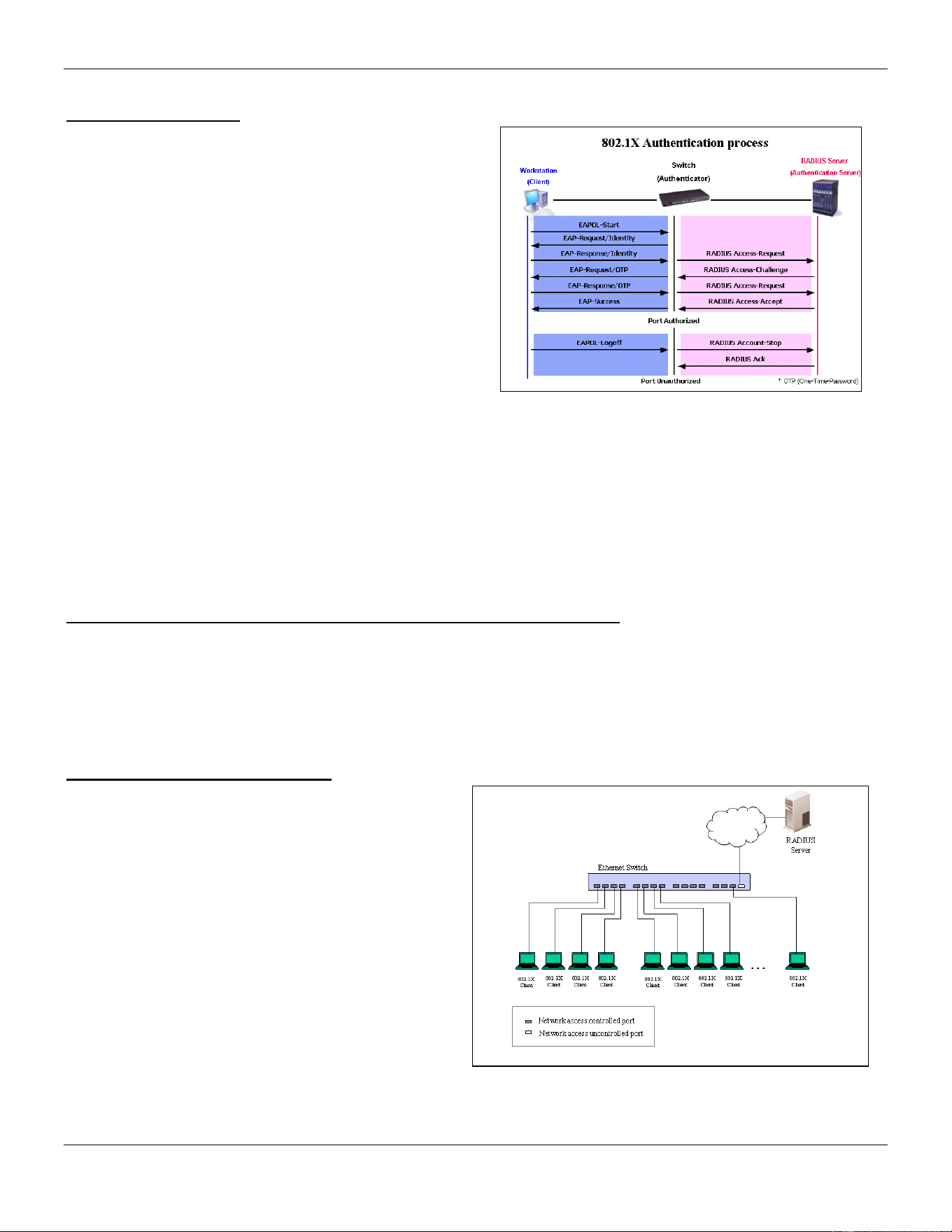
xStack® DGS-3420 Series Layer 2 Managed Stackable Gigabit Switch Web UI Reference Guide
279
Authentication Process
Utilizing the three roles stated above, the 802.1X protocol
provides a stable and secure way of authorizing and
authenticating users attempting to access the network.
Only EAPOL traffic is allowed to pass through the
specified port before a successful authentication is made.
This port is “locked” until the point when a Client with the
correct username and password (and MAC address if
802.1X is enabled by MAC address) is granted access
and therefore successfully “unlocks” the port. Once
unlocked, normal traffic is allowed to pass through the
port. The following figure displays a more detailed
explanation of how the authentication process is
completed between the three roles stated above.
Figure 8-6 The 802.1X Authentication Process
The D-Link implementation of 802.1X allows network administrators to choose between two types of Access Control
used on the Switch, which are:
1. Port-Based Access Control – This method requires only one user to be authenticated per port by a remote
RADIUS server to allow the remaining users on the same port access to the network.
2. Host-Based Access Control – Using this method, the Switch will automatically learn up to a maximum of 448
MAC addresses by port and set them in a list. Each MAC address must be authenticated by the Switch using a
remote RADIUS server before being allowed access to the Network.
Understanding 802.1X Port-based and Host-based Network Access Control
The original intent behind the development of 802.1X was to leverage the characteristics of point-to-point in LANs. As
any single LAN segment in such infrastructures has no more than two devices attached to it, one of which is a Bridge
Port. The Bridge Port detects events that indicate the attachment of an active device at the remote end of the link, or
an active device becoming inactive. These events can be used to control the authorization state of the Port and initiate
the process of authenticating the attached device if the Port is unauthorized. This is the Port-Based Network Access
Control.
Port-based Network Access Control
Once the connected device has successfully been
authenticated, the Port then becomes Authorized, and
all subsequent traffic on the Port is not subject to
access control restriction until an event occurs that
causes the Port to become Unauthorized. Hence, if the
Port is actually connected to a shared media LAN
segment with more than one attached device,
successfully authenticating one of the attached devices
effectively provides access to the LAN for all devices
on the shared segment. Clearly, the security offered in
this situation is open to attack.
Figure 8-7 Example of Typical Port-based Configuration
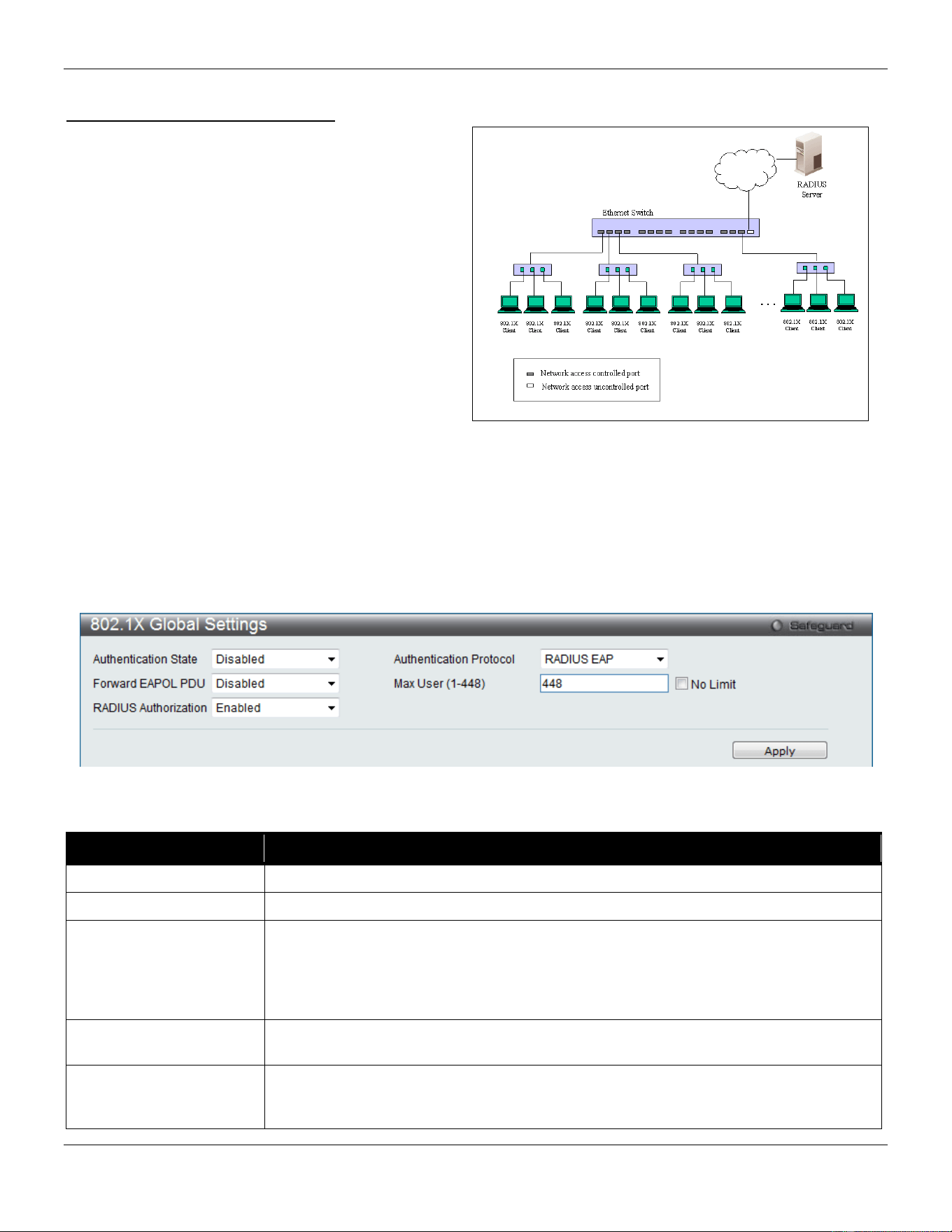
xStack® DGS-3420 Series Layer 2 Managed Stackable Gigabit Switch Web UI Reference Guide
280
Host-based Network Access Control
In order to successfully make use of 802.1X in a
shared media LAN segment, it would be necessary to
create “logical” Ports, one for each attached device
that required access to the LAN. The Switch would
regard the single physical Port connecting it to the
shared media segment as consisting of a number of
distinct logical Ports, each logical Port being
independently controlled from the point of view of
EAPOL exchanges and authorization state. The Switch
learns each attached devices’ individual MAC
addresses, and effectively creates a logical Port that
the attached device can then use to communicate with
the LAN via the Switch.
Figure 8-8 Example of Typical Host-based Configuration
802.1X Global Settings
Users can configure the 802.1X global parameter.
To view this window, click Security > 802.1X > 802.1X Global Settings as shown below:
Figure 8-9 802.1X Global Settings window
The fields that can be configured are described below:
Parameter Description
Authentication State
Use the drop-down menu to enable or disable the 802.1X function.
Authentication Protocol
Choose the authenticator protocol, Local or RADIUS EAP.
Forward EAPOL PDU
This is a global setting to control the forwarding of EAPOL PDU. When 802.1X
functionality is disabled globally or for a port, and if 802.1X forward PDU is enabled
both globally and for the port, a received EAPOL packet on the port will be flooded in
the same VLAN to those ports for which 802.1X forward PDU is enabled and 802.1X is
disabled (globally or just for the port). The default state is disabled.
Max Users Specifies the maximum number of users. The limit on the maximum users is 448 users.
This the No Limit check box to have unlimited users.
RADIUS Authorization
This option is used to enable or disable acceptation of authorized configuration. When
the authorization is enabled for 802.1X’s RADIUS, the authorized data assigned by the
RADIUS server will be accepted if the global authorization network is enabled.
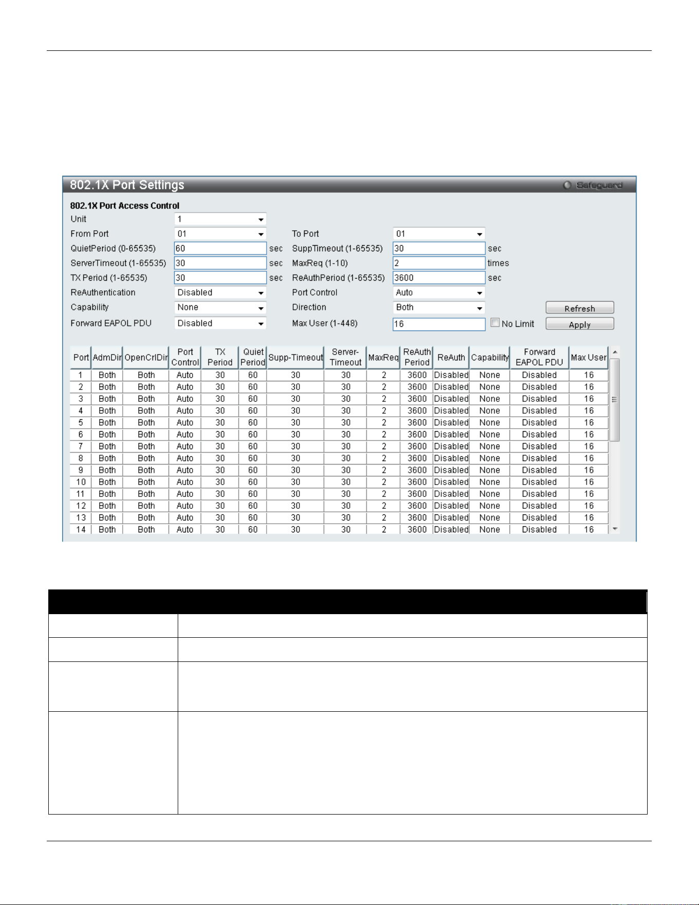
xStack® DGS-3420 Series Layer 2 Managed Stackable Gigabit Switch Web UI Reference Guide
281
Click the Apply button to accept the changes made.
802.1X Port Settings
Users can configure the 802.1X authenticator port settings.
To view this window, click Security > 802.1X > 802.1X Port Settings as shown below:
Figure 8-10 802.1X Port Settings
The fields that can be configured are described below:
Parameter Description
Unit
Select the unit you wish to configure.
From Port / To Port
Select a range of ports you wish to configure.
QuietPeriod
This allows the user to set the number of seconds that the Switch remains in the quiet
state following a failed authentication exchange with the client. The default setting is 60
seconds.
SuppTimeout
This value determines timeout conditions in the exchanges between the Authenticator and
the client. The default setting is 30 seconds. It is defined in SuppTimeout, IEEE-802.1X-
2001, page 47. The initialization value is used for the awhile timer when timing out the
Supplicant. Its default value is 30 seconds; however, if the type of challenge involved in
the current exchange demands a different value of timeout (for example, if the challenge
requires an action on the part of the user), then the timeout value is adjusted accordingly.
It can be set by management to any value in the range from 1 to 65535 seconds.

xStack® DGS-3420 Series Layer 2 Managed Stackable Gigabit Switch Web UI Reference Guide
282
ServerTimeout
This value determines timeout conditions in the exchanges between the Authenticator and
the authentication server. The default setting is 30 seconds.
MaxReq
The maximum number of times that the Switch will retransmit an EAP Request to the
client before it times out of the authentication sessions. The default setting is 2. It is
defined in MaxReq, IEEE-802.1X-2001 page 47. The maximum number of times that the
state machine will retransmit an EAP Request packet to the Supplicant before it times out
the authentication session. Its default value is 2; it can be set by management to any
value in the range from 1 to 10.
TxPeriod
This sets the TxPeriod of time for the authenticator PAE state machine. This value
determines the period of an EAP Request/Identity packet transmitted to the client. The
default setting is 30 seconds.
ReAuthPeriod
A constant that defines a nonzero number of seconds between periodic re-authentication
of the client. The default setting is 3600 seconds.
ReAuthentication
Determines whether regular re-authentication will take place on this port. The default
setting is Disabled.
Port Control
This allows the user to control the port authorization state.
• Select ForceAuthorized to disable 802.1X and cause the port to transition to the
authorized state without any authentication exchange required. This means the
port transmits and receives normal traffic without 802.1X-based authentication of
the client.
• If ForceUnauthorized is selected, the port will remain in the unauthorized state,
ignoring all attempts by the client to authenticate. The Switch cannot provide
authentication services to the client through the interface.
• If Auto is selected, it will enable 802.1X and cause the port to begin in the
unauthorized state, allowing only EAPOL frames to be sent and received through
the port. The authentication process begins when the link state of the port
transitions from down to up, or when an EAPOL-start frame is received. The
Switch then requests the identity of the client and begins relaying authentication
messages between the client and the authentication server.
The default setting is Auto.
Capability
This allows the 802.1X Authenticator settings to be applied on a per-port basis. Select
Authenticator to apply the settings to the port. When the setting is activated, a user must
pass the authentication process to gain access to the network. Select None disable
802.1X functions on the port.
Direction Sets the administrative-controlled direction to Both or In. If Both is selected, control is
exerted over both incoming and outgoing traffic through the controlled port selected in the
first field. If In is selected, the control is only exerted over incoming traffic through the port
the user selected in the first field.
Forward EAPOL PDU
This is a port-based setting to control the forwarding of EAPOL PDU. When 802.1X
functionality is disabled globally or for a port, and if 802.1X forward PDU is enabled both
globally and for the port, a received EAPOL packet on the port will be flooded in the same
VLAN to those ports for which 802.1X forward PDU is enabled and 802.1X is disabled
(globally or just for the port). The default state is disabled.
Max Users
Specifies the maximum number of users. The maximum user limit is 448 users. The
default is 16.
Click the Refresh button to refresh the display table so that new entries will appear.
Click the Apply button to accept the changes made.
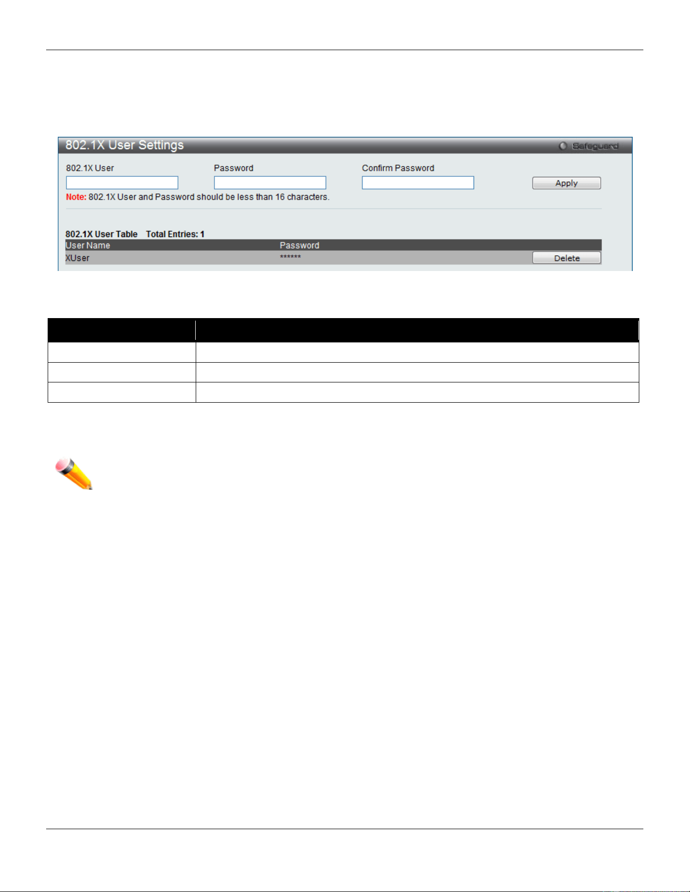
xStack® DGS-3420 Series Layer 2 Managed Stackable Gigabit Switch Web UI Reference Guide
283
802.1X User Settings
Users can set different 802.1X users in switch’s local database.
To view this window, click Security > 802.1X > 802.1X User Settings as shown below:
Figure 8-11 802.1X User Settings window
The fields that can be configured are described below:
Parameter Description
802.1X User
The user can enter an 802.1X user’s username in here.
Password
The user can enter an 802.1X user’s password in here.
Confirm Password
The user can re-enter an 802.1X user’s password in here.
Click the Apply button to accept the changes made.
Click the Delete button to remove the specific entry.
NOTE: The 802.1X User and Password values should be less than 16 characters.
Guest VLAN Settings
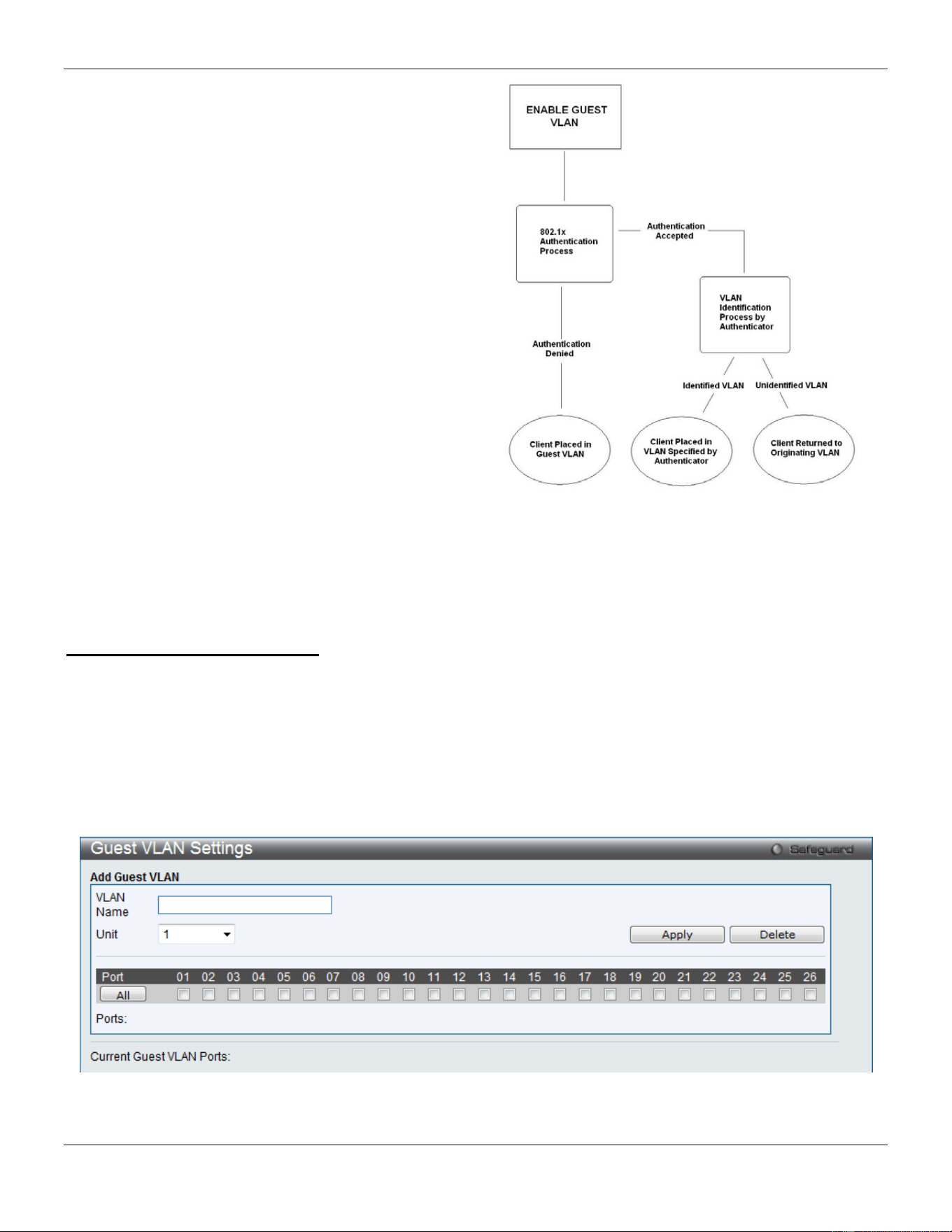
xStack® DGS-3420 Series Layer 2 Managed Stackable Gigabit Switch Web UI Reference Guide
284
On 802.1X security-enabled networks, there is a need for
non- 802.1X supported devices to gain limited access to
the network, due to lack of the proper 802.1X software or
incompatible devices, such as computers running
Windows 98 or older operating systems, or the need for
guests to gain access to the network without full
authorization or local authentication on the Switch. To
supplement these circumstances, this switch now
implements 802.1X Guest VLANs. These VLANs should
have limited access rights and features separate from
other VLANs on the network.
To implement 802.1X Guest VLANs, the user must first
create a VLAN on the network with limited rights and then
enable it as an 802.1X guest VLAN. Then the
administrator must configure the guest accounts
accessing the Switch to be placed in a Guest VLAN when
trying to access the Switch. Upon initial entry to the
Switch, the client wishing services on the Switch will need
to be authenticated by a remote RADIUS Server or local
authentication on the Switch to be placed in a fully
operational VLAN.
Figure 8-12 Guest VLAN Authentication Process
If authenticated and the authenticator possess the VLAN placement information, that client will be accepted into the
fully operational target VLAN and normal switch functions will be open to the client. If the authenticator does not have
target VLAN placement information, the client will be returned to its originating VLAN. Yet, if the client is denied
authentication by the authenticator, it will be placed in the Guest VLAN where it has limited rights and access. The
adjacent figure should give the user a better understanding of the Guest VLAN process.
Limitations Using the Guest VLAN
1. Ports supporting Guest VLANs cannot be GVRP enabled and vice versa.
2. A port cannot be a member of a Guest VLAN and a static VLAN simultaneously.
3. Once a client has been accepted into the target VLAN, it can no longer access the Guest VLAN.
Remember, to set an 802.1X guest VLAN, the user must first configure a normal VLAN, which can be enabled here for
guest VLAN status. Only one VLAN may be assigned as the 802.1X guest VLAN.
To view this window, click Security > 802.1X > Guest VLAN Settings as shown below:
Figure 8-13 Guest VLAN Settings window
The fields that can be configured are described below:
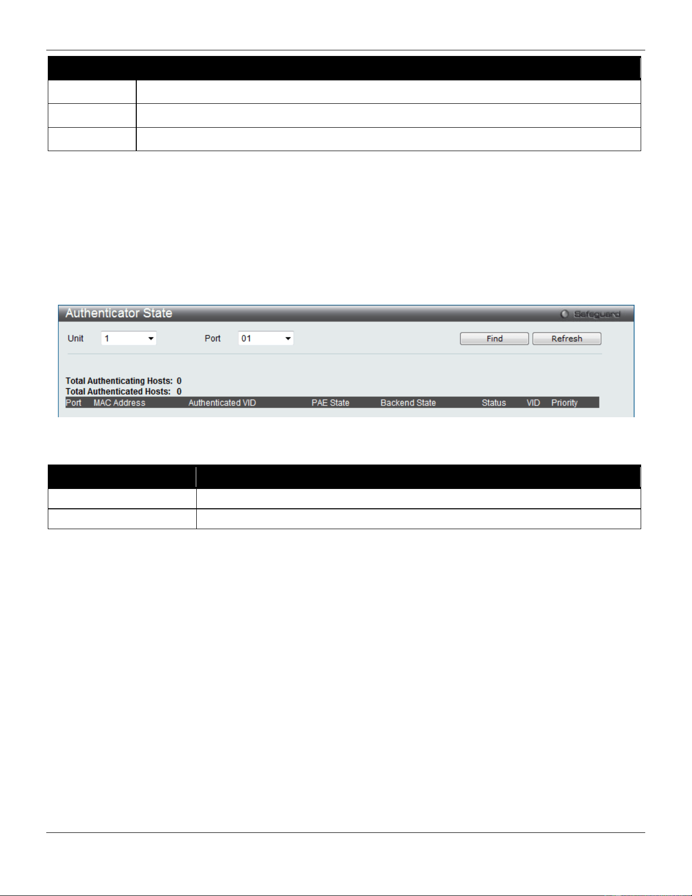
xStack® DGS-3420 Series Layer 2 Managed Stackable Gigabit Switch Web UI Reference Guide
285
Parameter Description
VLAN Name
Enter the pre-configured VLAN name to create as an 802.1X guest VLAN.
Unit
Select the unit you wish to configure.
Port Set the ports to be enabled for the 802.1X guest VLAN. Click the All button to select all the ports.
Click the Apply button to accept the changes made.
Click the Delete button to remove the specific entry based on the information entered.
Authenticator State
This window is used to display the authenticator state.
This window appears when the Authentication State is enabled in 802.1X Global Settings window.
To view this window, click Security > 802.1X > Authenticator State as shown below:
Figure 8-14 Authenticator State Window
The fields that can be configured are described below:
Parameter Description
Unit
Select a unit you want to display.
Port
Use the drop-down menu to select a port to display.
Click the Find button to locate a specific entry based on the information entered.
Click the Refresh button to refresh the display table so that new entries will appear.
Authenticator Statistics
This window is used to display the authenticator statistics information.
This window appears when the Authentication State is enabled in 802.1X Global Settings window.
To view this window, click Security > 802.1X > Authenticator Statistics as shown below:
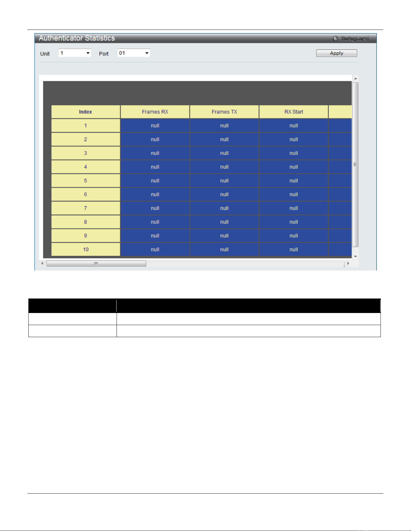
xStack® DGS-3420 Series Layer 2 Managed Stackable Gigabit Switch Web UI Reference Guide
286
Figure 8-15 Authenticator Statistics Window
The fields that can be configured are described below:
Parameter Description
Unit
Select a unit you want to display.
Port
Use the drop-down menu to select a port to display.
Click the Apply button to accept the changes made.
Authenticator Session Statistics
This window is used to display the authenticator session statistics information.
This window appears when the Authentication State is enabled in 802.1X Global Settings window.
To view this window, click Security > 802.1X > Authenticator Session Statistics as shown below:
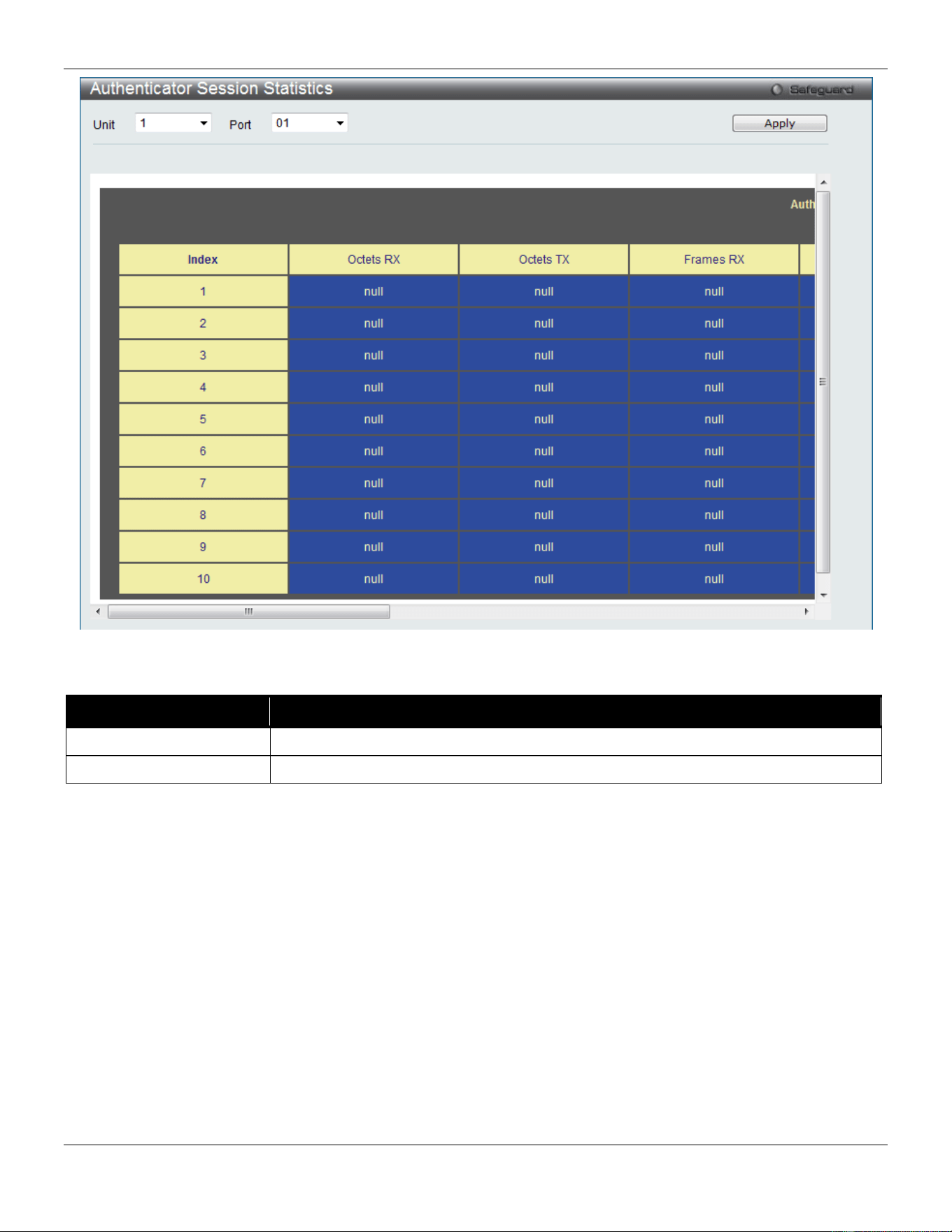
xStack® DGS-3420 Series Layer 2 Managed Stackable Gigabit Switch Web UI Reference Guide
287
Figure 8-16 Authenticator Session Statistics Window
The fields that can be configured are described below:
Parameter Description
Unit
Select a unit you want to display.
Port
Use the drop-down menu to select a port to display.
Click the Apply button to accept the changes made.
Authenticator Diagnostics
This window is used to display the authenticator diagnostics information.
This window appears when the Authentication State is enabled in 802.1X Global Settings window.
To view this window, click Security > 802.1X > Authenticator Diagnostics as shown below:
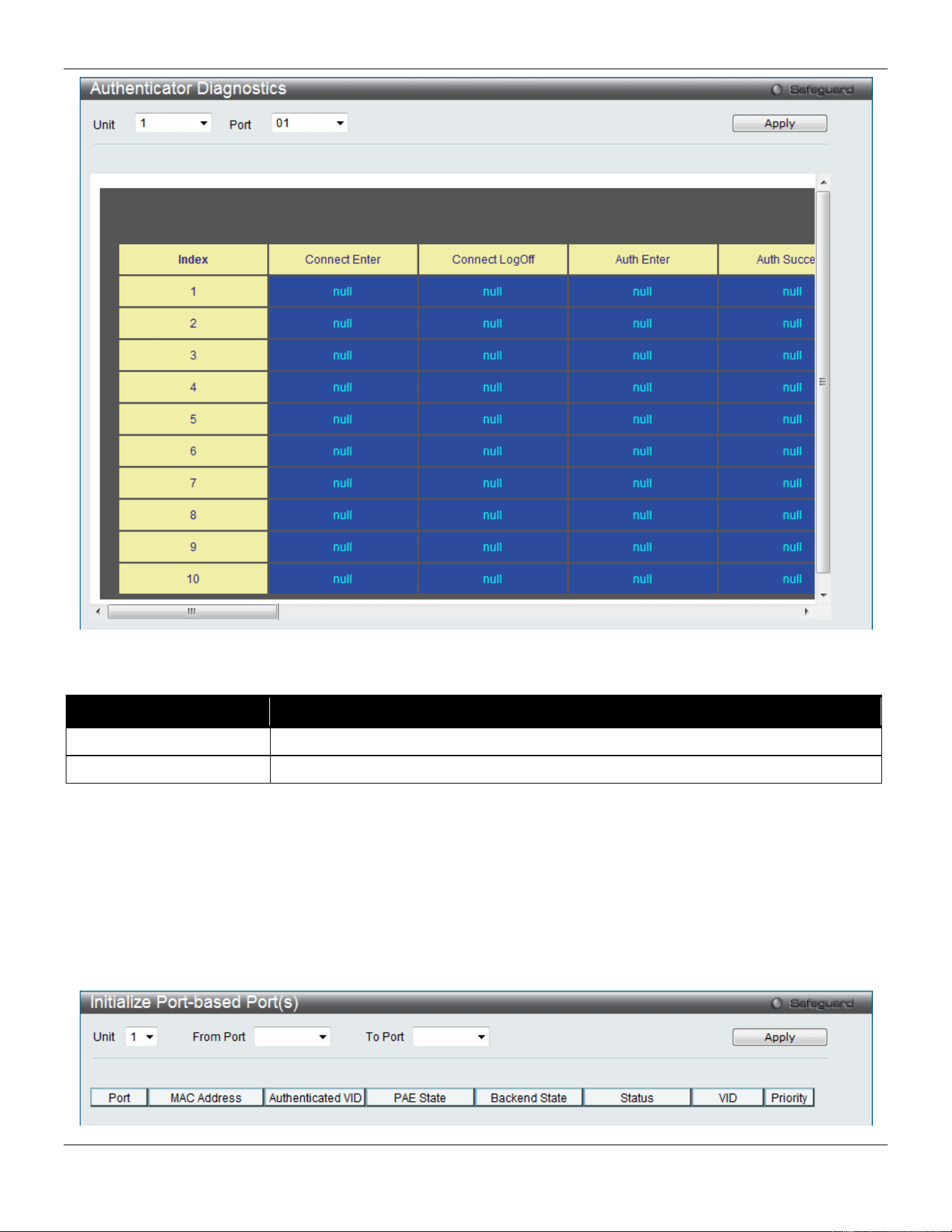
xStack® DGS-3420 Series Layer 2 Managed Stackable Gigabit Switch Web UI Reference Guide
288
Figure 8-17 Authenticator Diagnostics Window
The fields that can be configured are described below:
Parameter Description
Unit
Select a unit you want to display.
Port
Use the drop-down menu to select a port to display.
Click the Apply button to accept the changes made.
Initialize Port-based Port(s)
This window is used to initialize the 802.1X authentication state machine of port-based ports and displays the current
initialized port-based ports.
This window appears when the Authentication State is enabled in 802.1X Global Settings window.
To view this window, click Security > 802.1X > Initialize Port-based Port(s) as shown below:
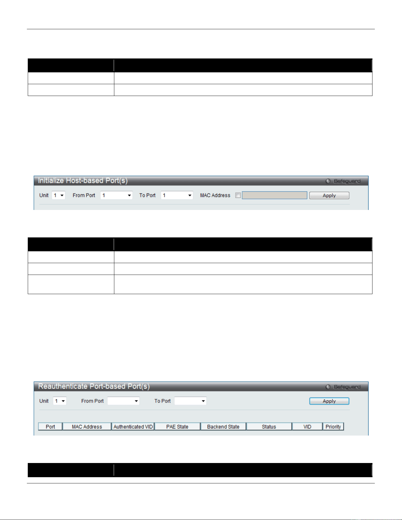
xStack® DGS-3420 Series Layer 2 Managed Stackable Gigabit Switch Web UI Reference Guide
289
Figure 8-18 Initialize Port-based Port(s) Window
The fields that can be configured are described below:
Parameter Description
Unit
Select a unit you want to display.
From Port / To Port
Use the drop-down menus to select a range of ports to initialize.
Click the Apply button to accept the changes made.
Initialize Host-based Port(s)
This window is used to initialize the 802.1X authentication state machine of host-based ports.
This window appears when the Authentication State is enabled in 802.1X Global Settings window.
To view this window, click Security > 802.1X > Initialize Host-based Port(s) as shown below:
Figure 8-19 Initialize Host-based Port(s) Window
The fields that can be configured are described below:
Parameter Description
Unit
Select a unit you want to display.
From Port / To Port
Use the drop-down menus to select a range of ports to initialize.
MAC Address
Tick the check box and enter the MAC address of the Switch connected to the
corresponding port, if any.
Click the Apply button to accept the changes made.
Reauthenticate Port-based Port(s)
This window is used to re-authenticate the device connected with the port-based ports and display the current status of
the re-authenticated port-based port(s).
This window appears when the Authentication State is enabled in 802.1X Global Settings window.
To view this window, click Security > 802.1X > Reauthenticate Port-based Port(s) as shown below:
Figure 8-20 Reauthenticate Port-based Port(s) Window
The fields that can be configured are described below:
Parameter Description
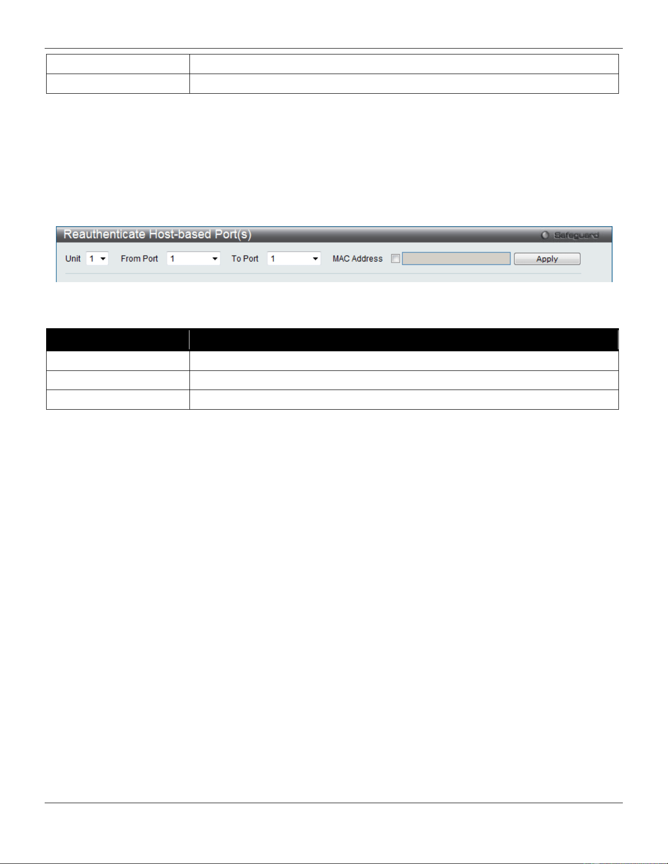
xStack® DGS-3420 Series Layer 2 Managed Stackable Gigabit Switch Web UI Reference Guide
290
Unit
Select a unit you want to display.
From Port / To Port
Use the drop-down menus to select a range of ports to re-authenticated.
Click the Apply button to accept the changes made.
Reauthenticate Host-based Port(s)
This window is used to re-authenticate the device connected with the host-based ports.
This window appears when the Authentication State is enabled in 802.1X Global Settings window.
To view this window, click Security > 802.1X > Reauthenticate Host-based Port(s) as shown below:
Figure 8-21 Reauthenticate Host-based Port(s) Window
The fields that can be configured are described below:
Parameter Description
Unit
Select a unit you want to display.
From Port / To Port
Use the drop-down menus to select a range of ports to re-authenticated.
MAC Address
Tick the check box and enter the MAC address.
Click the Apply button to accept the changes made.
RADIUS
Authentication RADIUS Server Settings
The RADIUS feature of the Switch allows the user to facilitate centralized user administration as well as providing
protection against a sniffing, active hacker.
To view this window, click Security > RADIUS > Authentication RADIUS Server Settings as shown below:
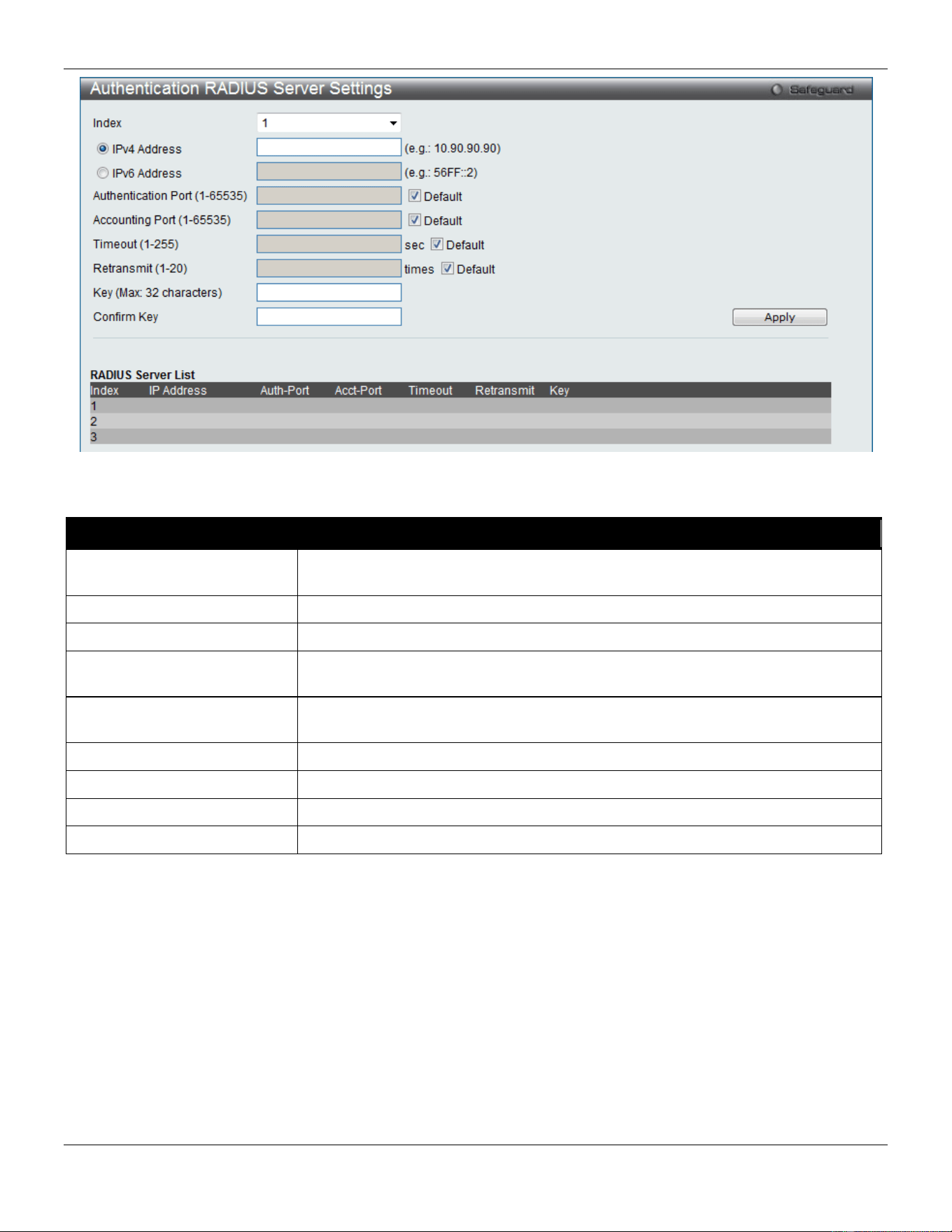
xStack® DGS-3420 Series Layer 2 Managed Stackable Gigabit Switch Web UI Reference Guide
291
Figure 8-22 Authentication RADIUS Server Settings window
The fields that can be configured are described below:
Parameter Description
Index Choose the desired RADIUS server to configure: 1, 2 or 3 and select the IPv4
Address.
IPv4 Address
Set the RADIUS server IP address.
IPv6 Address
Set the RADIUS server IPv6 address.
Authentication Port
(1-65535)
Set the RADIUS authentication server(s) UDP port which is used to transmit
RADIUS data between the Switch and the RADIUS server.
Accounting Port (1-65535)
Set the RADIUS account server(s) UDP port which is used to transmit RADIUS
accounting statistics between the Switch and the RADIUS server.
Timeout (1-255)
Set the RADIUS server age-out, in seconds.
Retransmit (1-20)
Set the RADIUS server retransmit time, in times.
Key
Set the key the same as that of the RADIUS server.
Confirm Key
Confirm the key the same as that of the RADIUS server.
Click the Apply button to accept the changes made.
RADIUS Authentication
Users can display information concerning the activity of the RADIUS authentication client on the client side of the
RADIUS authentication protocol.
To view this window, click Security > RADIUS > RADIUS Authentication as shown below:
xStack® DGS-3420 Series Layer 2 Managed Stackable Gigabit Switch Web UI Reference Guide
292
Figure 8-23 RADIUS Authentication window
The user may also select the desired time interval to update the statistics, between 1s and 60s, where “s” stands for
seconds. The default value is one second.
The fields that can be configured are described below:
Parameter Description
InvalidServerAddr
The number of RADIUS Access-Response packets received from unknown addresses.
Identifier
The NAS-Identifier of the RADIUS authentication client.
ServerIndex
The identification number assigned to each RADIUS Authentication server that the
client shares a secret with.
AuthServerAddr
The (conceptual) table listing the RADIUS authentication servers with which the client
shares a secret.
ServerPortNumber
The UDP port the client is using to send requests to this server.
RoundTripTime
The time interval (in hundredths of a second) between the most recent Access-
Reply/Access-Challenge and the Access-Request that matched it from this RADIUS
authentication server.
AccessRequests
The number of RADIUS Access-Request packets sent to this server. This does not
include retransmissions.
AccessRetrans
The number of RADIUS Access-Request packets retransmitted to this RADIUS
authentication server.
AccessAccepts
The number of RADIUS Access-Accept packets (valid or invalid) received from this
server.
AccessRejects
The number of RADIUS Access-Reject packets (valid or invalid) received from this
server.
AccessChallenges
The number of RADIUS Access-Challenge packets (valid or invalid) received from this
server.
AccessResponses
The number of malformed RADIUS Access-Response packets received from this
server. Malformed packets include packets with an invalid length. Bad authenticators
or Signature attributes or known types are not included as malformed access
responses.
BadAuthenticators
The number of RADIUS Access-Response packets containing invalid authenticators or
Signature attributes received from this server.
xStack® DGS-3420 Series Layer 2 Managed Stackable Gigabit Switch Web UI Reference Guide
293
PendingRequests
The number of RADIUS Access-Request packets destined for this server that have not
yet timed out or received a response. This variable is incremented when an Access-
Request is sent and decremented due to receipt of an Access-Accept, Access-Reject
or Access-Challenge, a timeout or retransmission.
Timeouts
The number of authentication timeouts to this server. After a timeout the client may
retry to the same server, send to a different server, or give up. A retry to the same
server is counted as a retransmit as well as a timeout. A send to a different server is
counted as a Request as well as a timeout.
UnknownTypes
The number of RADIUS packets of unknown type which were received from this server
on the authentication port
PacketsDropped
The number of RADIUS packets of which were received from this server on the
authentication port and dropped for some other reason.
Click the Clear button to clear the current statistics shown.
RADIUS Account Client
Users can display managed objects used for managing RADIUS accounting clients, and the current statistics
associated with them.
To view this window, click Security > RADIUS > RADIUS Account Client as shown below:
Figure 8-24 RADIUS Account Client window
The user may also select the desired time interval to update the statistics, between 1s and 60s, where “s” stands for
seconds. The default value is one second.
The fields that can be configured are described below:
Parameter Description
ServerIndex
The identification number assigned to each RADIUS Accounting server that the client
shares a secret with.
InvalidServerAddr
The number of RADIUS Accounting-Response packets received from unknown
addresses.
Identifier
The NAS-Identifier of the RADIUS accounting client.
ServerAddr
The IP address of the RADIUS authentication server referred to in this table entry.
ServerPortNumber
The UDP port the client is using to send requests to this server.

xStack® DGS-3420 Series Layer 2 Managed Stackable Gigabit Switch Web UI Reference Guide
294
RoundTripTime
The time interval between the most recent Accounting-Response and the Accounting-
Request that matched it from this RADIUS accounting server.
Requests
The number of RADIUS Accounting-Request packets sent. This does not include
retransmissions.
Retransmissions
The number of RADIUS Accounting-Request packets retransmitted to this RADIUS
accounting server. Retransmissions include retries where the Identifier and Acct-Delay
have been updated, as well as those in which they remain the same.
Responses
The number of RADIUS packets received on the accounting port from this server.
MalformedResponses
The number of malformed RADIUS Accounting-Response packets received from this
server. Malformed packets include packets with an invalid length. Bad authenticators and
unknown types are not included as malformed accounting responses.
BadAuthenticators
The number of RADIUS Accounting-Response packets, which contained invalid
authenticators, received from this server.
PendingRequests
The number of RADIUS Accounting-Request packets sent to this server that have not yet
timed out or received a response. This variable is incremented when an Accounting-
Request is sent and decremented due to receipt of an Accounting-Response, a timeout or
a retransmission.
Timeouts
The number of accounting timeouts to this server. After a timeout the client may retry to
the same server, send to a different server, or give up. A retry to the same server is
counted as a retransmit as well as a timeout. A send to a different server is counted as an
Accounting-Request as well as a timeout.
UnknownTypes
The number of RADIUS packets of unknown type which were received from this server on
the accounting port.
PacketsDropped
The number of RADIUS packets, which were received from this server on the accounting
port and dropped for some other reason.
Click the Clear button to clear the current statistics shown.
IP-MAC-Port Binding (IMPB)
The IP network layer uses a IPv4/IPv6 address. The Ethernet link layer uses a MAC address. Binding these two
address types together allows the transmission of data between the layers. The primary purpose of IP-MAC-port
binding is to restrict the access to a switch to a number of authorized users. Authorized clients can access a switch’s
port by either checking the pair of IP-MAC addresses with the pre-configured database or if DHCP snooping has been
enabled in which case the switch will automatically learn the IP/MAC pairs by snooping DHCP packets and saving
them to the IMPB white list. If an unauthorized user tries to access an IP-MAC binding enabled port, the system will
block the access by dropping its packet. For the xStack
®
DGS-3420 series of switches, active and inactive entries use
the same database. The maximum number of IPv4/IPv6 entries is 510/511. The creation of authorized users can be
manually configured by CLI or Web. The function is port-based, meaning a user can enable or disable the function on
the individual port.
IMPB Global Settings
Users can enable or disable the Trap/Log State and DHCP Snoop state on the Switch. The Trap/Log field will enable
and disable the sending of trap/log messages for IP-MAC-port binding. When enabled, the Switch will send a trap
message to the SNMP agent and the Switch log when an ARP/IP packet is received that doesn’t match the IP-MAC-
port binding configuration set on the Switch.
To view this window, click Security > IP-MAC-Port Binding (IMPB) > IMPB Global Settings as shown below:
xStack® DGS-3420 Series Layer 2 Managed Stackable Gigabit Switch Web UI Reference Guide
295
Figure 8-25 IMPB Global Settings
The fields that can be configured are described below:
Parameter Description
Roaming State
Select to enable or disable the roaming state. When IMPB roaming is enabled, the
dynamic authenticated MAC address which learned through DHCP/ND snooping on
specific port can change to another port if it detects (1) a new DHCP process belong to
same IP and MAC address or (2) a new DAD process belong to same IP and MAC.
Trap / Log
Click the radio buttons to enable or disable the sending of trap/log messages for IP-
MAC-port binding. When Enabled, the Switch will send a trap message to the SNMP
agent and the Switch log when an ARP/IP packet is received that doesn’t match the IP-
MAC-port binding configuration set on the Switch. The default is Disabled.
DHCP Snooping (IPv4)
Click the radio buttons to enable or disable DHCP snooping (IPv4) for IP-MAC-port
binding. The default is Disabled.
DHCP Snooping (IPv6)
Click the radio buttons to enable or disable DHCP snooping (IPv6) for IP-MAC-port
binding. The default is Disabled.
ND Snooping
Click the radio buttons to enable or disable enable ND snooping on the Switch. The
default is Disabled.
Recover Learning Ports Enter the port numbers used to recover the learning port state. Tick the All check box
to apply to all ports.
File Name
This option is used to download or upload DHCPv4 Snooping binding entries by TFTP.
Enter the file path, to the TFTP server, here. Alternatively, click on the Browse button
and navigate to the file located on the PC. Click the Download button to initiate the
download. Click the Upload button to initiate the upload.
Address Binding DHCP
Snooping Entry File
This option is used to save the DHCPv4 snooping binding entries. Enter the filename
here. Note: This feature is only supported on devices that support external memory
(e.g. SD card).
Auto Save
Select to enable or disable the automatic save option.
xStack® DGS-3420 Series Layer 2 Managed Stackable Gigabit Switch Web UI Reference Guide
296
Save DHCP Snooping
Binding Entry
Click the Save button to manually initiate the saving of the DHCP snooping binding
entry here.
Click the Apply button to accept the changes made for each individual section.
IMPB Port Settings
Select a port or a range of ports with the From Port and To Port fields. Enable or disable the port with the State, Allow
Zero IP and Forward DHCP Packet field, and configure the port’s Max Entry.
To view this window, click Security > IP-MAC-Port Binding (IMPB) > IMPB Port Settings as shown below:
Figure 8-26 IMPB Port Settings window
The fields that can be configured are described below:
Parameter Description
Unit
Select the unit you wish to configure.
From Port / To Port
Select a range of ports to set for IP-MAC-port binding.
ARP Inspection
When the ARP inspection function is enabled, the legal ARP packets are forwarded,
while the illegal packets are dropped.
Disabled - Disable the ARP inspection function.
Enabled (Strict) - This mode disables hardware learning of the MAC address. All packets
are dropped by default until a legal ARP or IP packets are detected. When enabling this
mode, the Switch stops writing dropped FDB entries on these ports. If detecting legal
packets, the Switch needs to write forward FDB entry.
Enabled (Loose) - In this mode, all packets are forwarded by default until an illegal ARP
packet is detected.
The default value is Disabled.
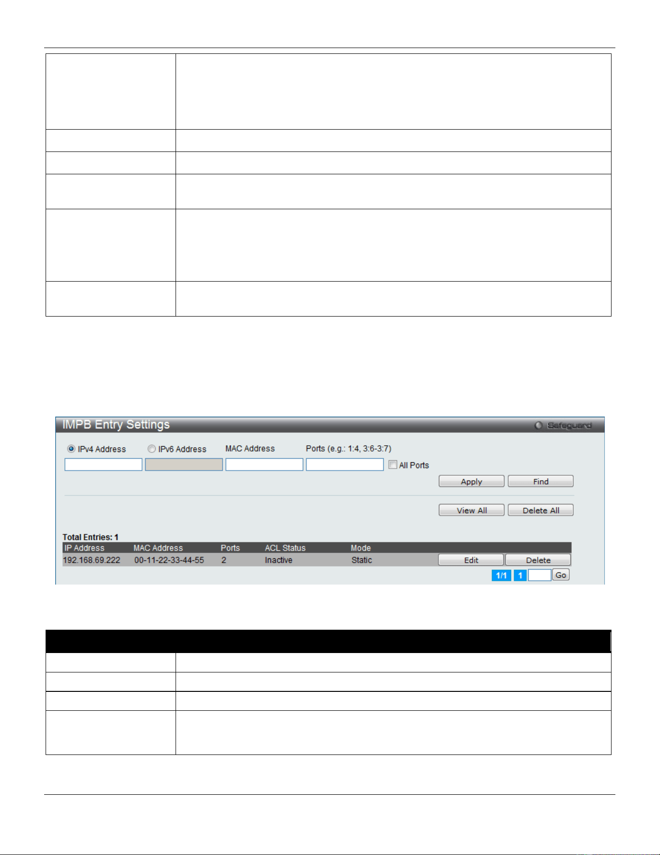
xStack® DGS-3420 Series Layer 2 Managed Stackable Gigabit Switch Web UI Reference Guide
297
IP Inspection
When both ARP and IP inspections are enabled, all IP packets are checked. The legal
IP packets are forwarded, while the illegal IP packets are dropped. When IP Inspection
is enabled, and ARP Inspection is disabled, all non-IP packets (Ex. L2 packets, or ARP)
are forwarded by default.
The default value is Disabled.
ND Inspection Select to enable or disable enable ND snooping on the Switch. The default is Disabled.
Protocol Use the drop-down menu to select the protocol types, IPv4, IPv6 or All.
Zero IP
Use the drop-down menu to enable or disable this feature. Allow zero IP configures the
state which allows ARP packets with 0.0.0.0 source IP to bypass.
DHCP Packet
By default, the DHCP packet with broadcast DA will be flooded. When set to disable, the
broadcast DHCP packet received by the specified port will not be forwarded in strict
mode. This setting is effective when DHCP snooping is enabled, in the case when a
DHCP packet which has been trapped by the CPU needs to be forwarded by the
software. This setting controls the forwarding behavior in this situation.
Stop Learning
Threshold
Here is displayed the number of blocked entries on the port. The default value is 500.
Click the Apply button to accept the changes made.
IMPB Entry Settings
This window is used to create static IP-MAC-binding port entries and view all IMPB entries on the Switch.
To view this window, click Security > IP-MAC-Port Binding (IMPB) > IMPB Entry Settings as shown below:
Figure 8-27 IMPB Entry Settings window
The fields that can be configured are described below:
Parameter Description
IPv4 Address
Click the radio button and enter the IP address to bind to the MAC address set below.
IPv6 Address
Click the radio button and enter the IPv6 address to bind to the MAC address set below.
MAC Address
Enter the MAC address to bind to the IP Address set above.
Ports
Specify the switch ports for which to configure this IP-MAC binding entry (IP Address +
MAC Address). Tick the All Ports check box to configure this entry for all ports on the
Switch.
Click the Apply button to accept the changes made.
Click the Find button to locate a specific entry based on the information entered.
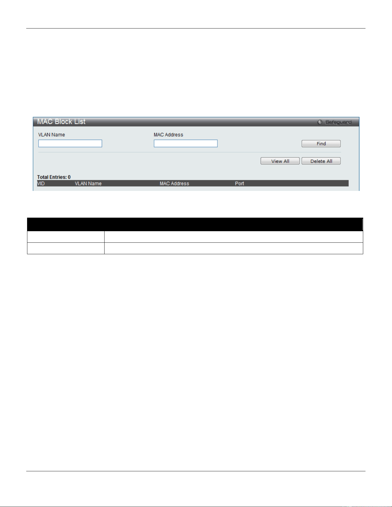
xStack® DGS-3420 Series Layer 2 Managed Stackable Gigabit Switch Web UI Reference Guide
298
Click the View All button to display all the existing entries.
Click the Delete All button to remove all the entries listed.
Click the Edit button to configure the specified entry.
Click the Delete button to remove the specified entry.
MAC Block List
This window is used to view unauthorized devices that have been blocked by IP-MAC binding restrictions.
To view this window, click Security > IP-MAC-Port Binding (IMPB) > MAC Block List as shown below:
Figure 8-28 MAC Block List
The fields that can be configured are described below:
Parameter Description
VLAN Name
Enter a VLAN Name.
MAC Address
Enter a MAC address.
Click the Find button to find an unauthorized device that has been blocked by the IP-MAC binding restrictions
Click the View All button to display all the existing entries.
Click the Delete All button to remove all the entries listed.
DHCP Snooping
DHCP Snooping Maximum Entry Settings
Users can configure the maximum DHCP snooping entry for ports on this page.
To view this window, click Security > IP-MAC-Port Binding (IMPB) > DHCP Snooping > DHCP Snooping
Maximum Entry Settings as shown below:
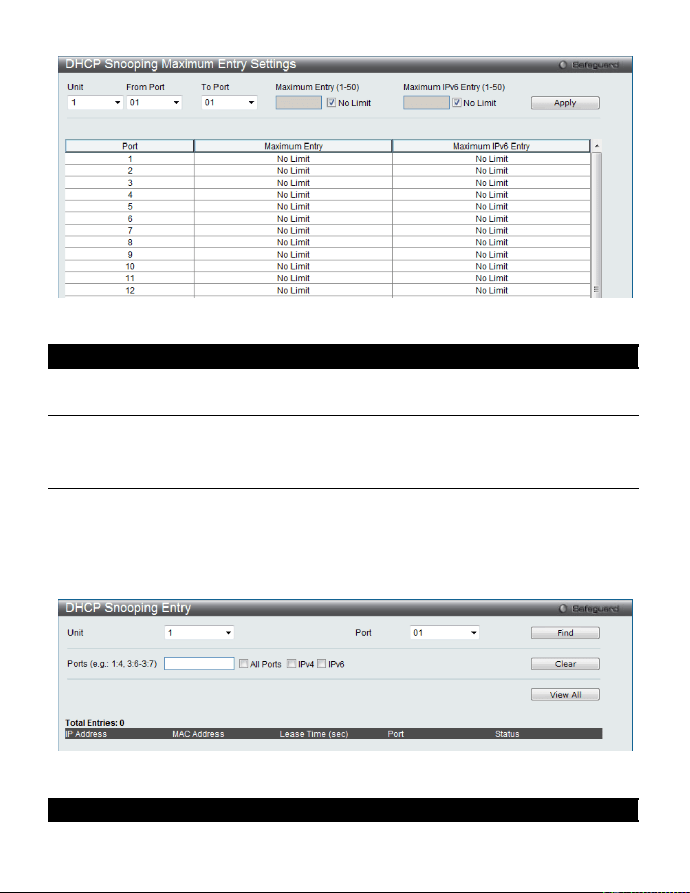
xStack® DGS-3420 Series Layer 2 Managed Stackable Gigabit Switch Web UI Reference Guide
299
Figure 8-29 DHCP Snooping Max Entry Settings window
The fields that can be configured are described below:
Parameter Description
Unit
Select the unit you wish to configure.
From Port / To Port
Use the drop-down menus to select a range of ports to use.
Maximum Entry (1-50) Enter the maximum entry value. Tick the No Limit check box to have unlimited
maximum number of the learned entries.
Maximum IPv6 Entry
(1-50)
Enter the maximum entry value for IPv6 DHCP Snooping. Tick the No Limit check box
to have unlimited maximum number of the learned entries.
Click the Apply button to accept the changes made.
DHCP Snooping Entry
This window is used to view dynamic entries on specific ports.
To view this window, click Security > IP-MAC-Port Binding (IMPB) > DHCP Snooping > DHCP Snooping Entry as
shown below:
Figure 8-30 DHCP Snooping Entry window
The fields that can be configured are described below:
Parameter Description
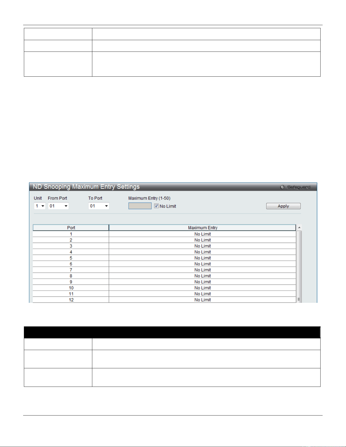
xStack® DGS-3420 Series Layer 2 Managed Stackable Gigabit Switch Web UI Reference Guide
300
Unit
Select the unit you wish to configure.
Port
Use the drop-down menu to select the desired port.
Ports Specify the ports for DHCP snooping entries. Tick the All Ports check box to select all
entries for all ports. Tick the IPv4 check box to select IPv4 DHCP snooping learned
entries. Tick the IPv6 check box to select IPv6 DHCP snooping learned entries..
Click the Find button to locate a specific entry based on the port number selected.
Click the Clear button to clear all the information entered in the fields.
Click the View All button to display all the existing entries.
ND Snooping
ND Snooping Maximum Entry Settings
Users can configure the maximum ND Snooping entry for ports on this page.
To view this window, click Security > IP-MAC-Port Binding (IMPB) > ND Snooping > ND Snooping Maximum
Entry Settings as shown below:
Figure 8-31 ND Snooping Maximum Entry Settings window
The fields that can be configured are described below:
Parameter Description
Unit
Select the unit you wish to configure.
From Port / To Port
Use the drop-down menus to select a range of ports that require a restriction on the
maximum number of entries that can be learned with ND snooping.
Maximum Entry (1-50) Enter the maximum entry value. Tick the No Limit check box to have unlimited
maximum number of the learned entries.
Click the Apply button to accept the changes made.
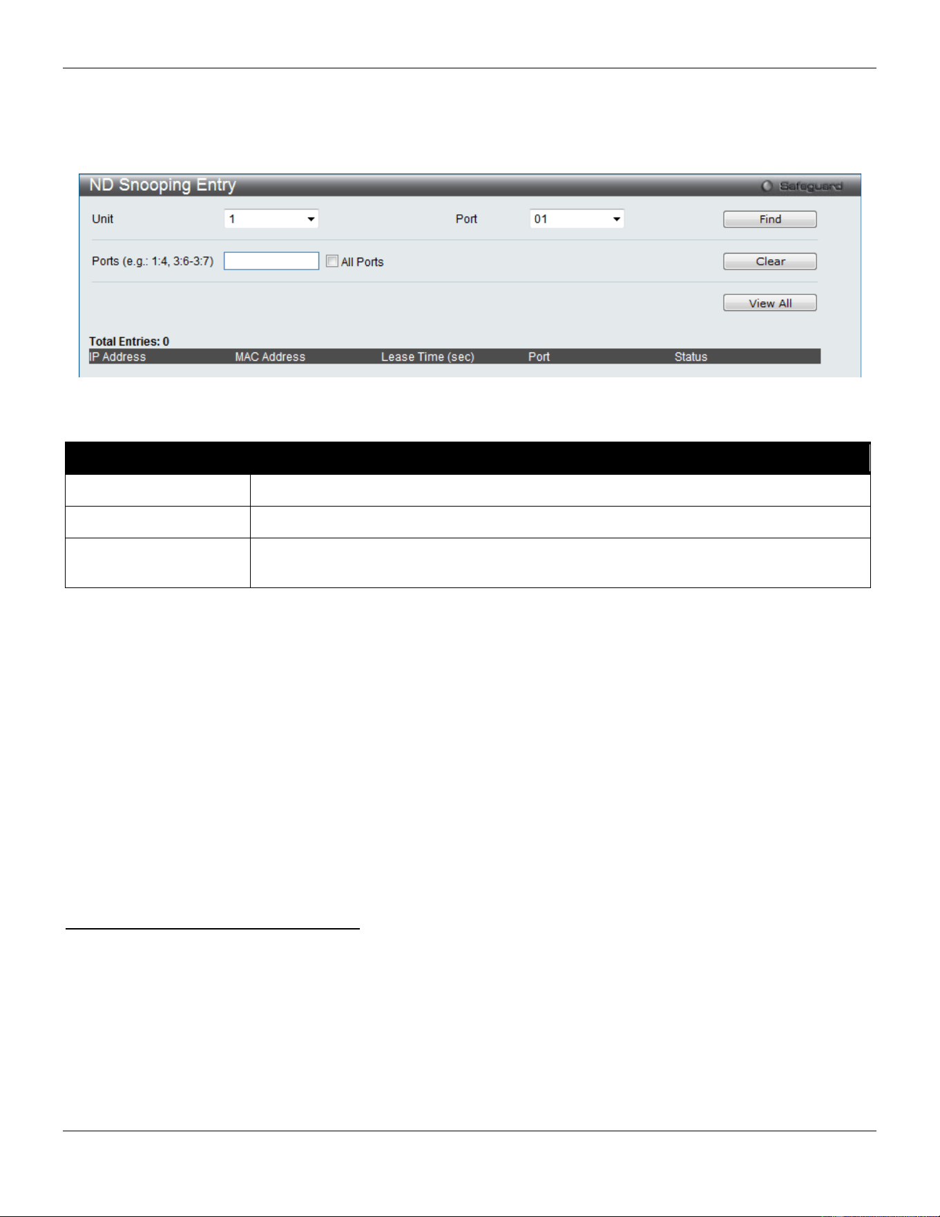
xStack® DGS-3420 Series Layer 2 Managed Stackable Gigabit Switch Web UI Reference Guide
301
ND Snooping Entry
This window is used to view dynamic entries on specific ports.
To view this window, click Security > IP-MAC-Port Binding (IMPB) > ND Snooping > ND Snooping Entry as shown
below:
Figure 8-32 ND Snooping Entry window
The fields that can be configured are described below:
Parameter Description
Unit
Select the unit you wish to configure.
Port
Use the drop-down menu to select the desired port.
Ports Specify the ports for ND snooping entries. Tick the All Ports check box to select all
entries for all ports.
Click the Find button to locate a specific entry based on the port number selected.
Click the Clear button to clear all the information entered in the fields.
Click the View All button to display all the existing entries.
MAC-based Access Control (MAC)
MAC-based access control is a method to authenticate and authorize access using either a port or host. For port-
based MAC-based access control, the method decides port access rights, while for host-based MAC-based access
control, the method determines the MAC access rights.
A MAC user must be authenticated before being granted access to a network. Both local authentication and remote
RADIUS server authentication methods are supported. In MAC-based access control, MAC user information in a local
database or a RADIUS server database is searched for authentication. Following the authentication result, users
achieve different levels of authorization.
Notes about MAC-based Access Control
There are certain limitations and regulations regarding MAC-based access control:
1. Once this feature is enabled for a port, the Switch will clear the FDB of that port.
2. If a port is granted clearance for a MAC address in a VLAN that is not a Guest VLAN, other MAC addresses on
that port must be authenticated for access and otherwise will be blocked by the Switch.
3. Ports that have been enabled for Link Aggregation and Port Security cannot be enabled for MAC-based
Authentication.
4. Ports that have been enabled for GVRP cannot be enabled for Guest VLAN.
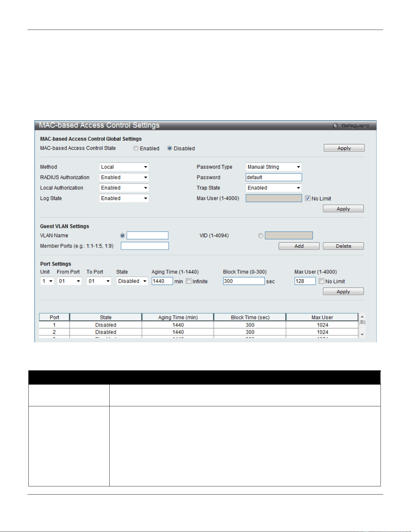
xStack® DGS-3420 Series Layer 2 Managed Stackable Gigabit Switch Web UI Reference Guide
302
MAC-based Access Control Settings
This window is used to set the parameters for the MAC-based access control function on the Switch. The user can set
the running state, method of authentication, RADIUS password, view the Guest VLAN configuration to be associated
with the MAC-based access control function of the Switch, and configure ports to be enabled or disabled for the MAC-
based access control feature of the Switch. Please remember, ports enabled for certain other features, listed
previously, and cannot be enabled for MAC-based access control.
To view this window, click Security > MAC-based Access Control (MAC) > MAC-based Access Control Settings
as shown below:
Figure 8-33 MAC-based Access Control Settings window
The fields that can be configured are described below:
Parameter Description
MAC-based Access
Control State
Toggle to globally enable or disable the MAC-based access control function on the
Switch.
Method
Use this drop-down menu to choose the type of authentication to be used when
authentication MAC addresses on a given port. The user may choose between the
following methods:
Local – Use this method to utilize the locally set MAC address database as the
authenticator for MAC-based access control. This MAC address list can be configured in
the MAC-based access control Local Database Settings window.
RADIUS – Use this method to utilize a remote RADIUS server as the authenticator for
MAC-based access control. Remember, the MAC list must be previously set on the
RADIUS server.

xStack® DGS-3420 Series Layer 2 Managed Stackable Gigabit Switch Web UI Reference Guide
303
RADIUS Authorization
Use the drop-down menu to enable or disable the use of RADIUS Authorization.
Local Authorization
Use the drop-down menu to enable or disable the use of Local Authorization.
Log State
Use the drop-down menu to enable or disable log state.
Password Type Use the drop-down menu to select the password type. Available options are Manual
String and Client MAC Address.
Password
Enter the password for the RADIUS server, which is to be used for packets being sent
requesting authentication. The default password is “default”.
Trap State
Use the drop-down menu to enable or disable sending out the trap for MAC-based
Access Control.
Max User (1-4000) Enter the maximum amount of users of the Switch. Tick the No Limit check box to have
unlimited users.
VLAN Name
Enter the name of the previously configured Guest VLAN being used for this function.
VID
Click the radio button and enter a Guest VLAN ID.
Member Ports
Enter the list of ports that have been configured for the Guest VLAN.
Unit
Select the unit you wish to configure.
From Port / To Port
Use the drop-down menus to select a range of ports to be configured for MAC-based
access control.
State
Use this drop-down menu to enable or disable MAC-based access control on the port or
range of ports selected in the Port Settings section of this window.
Aging Time (1-1440) Enter a value between 1 and 1440 minutes. The default is 1440. To set this value to
have no aging time, select the Infinite option.
Block Time (0-300) Enter a value between 0 and 300 seconds. The default is 300.
Max User (1-4000) Enter the maximum user used for this configuration. When No Limit is selected, there
will be no user limit applied to this rule.
Click the Apply button to accept the changes made for each individual section.
MAC-based Access Control Local Settings
Users can set a list of MAC addresses, along with their corresponding target VLAN, which will be authenticated for the
Switch. Once a queried MAC address is matched in this window, it will be placed in the VLAN associated with it here.
The Switch administrator may enter up to 1024 MAC addresses to be authenticated using the local method configured
here.
To view this window, click Security > MAC-based Access Control (MAC) > MAC-based Access Control Local
Settings as shown below:
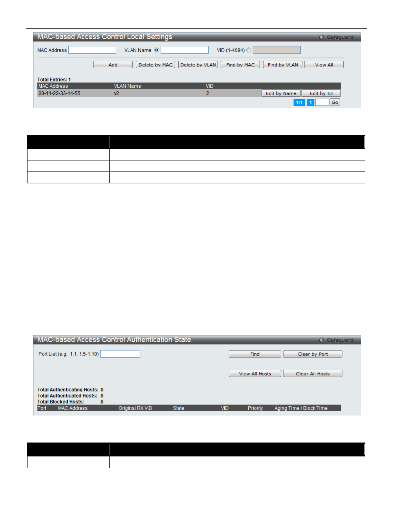
xStack® DGS-3420 Series Layer 2 Managed Stackable Gigabit Switch Web UI Reference Guide
304
Figure 8-34 MAC-based Access Control Local Settings window
The fields that can be configured are described below:
Parameter Description
MAC address
Enter the MAC address that will be added to the local authentication list here.
VLAN Name
Enter the VLAN name of the corresponding MAC address here.
VID (1-4094)
Enter the VLAN ID of the corresponding MAC address here.
Click the Add button to add a new entry based on the information entered.
Click the Delete by MAC button to remove the specific entry based on the MAC address entered.
Click the Delete by VLAN button to remove the specific entry based on the VLAN name or ID entered.
Click the Find by MAC button to locate a specific entry based on the MAC address entered.
Click the Find by VLAN button to locate a specific entry based on the VLAN name or ID entered.
Click the View All button to display all the existing entries.
Click the Edit by Name button to change the specific MAC address’ VLAN name.
Click the Edit by ID button to change the specific MAC address’ VLAN ID.
Enter a page number and click the Go button to navigate to a specific page when multiple pages exist.
MAC-based Access Control Authentication State
This window displays MAC-based access control Authentication State information.
To view this window, click Security > MAC-based Access Control (MAC) > MAC-based Access Control
Authentication State as shown below:
Figure 8-35 MAC-based Access Control Authentication State window
The fields that can be configured are described below:
Parameter Description
Port List
Enter a list of ports.

xStack® DGS-3420 Series Layer 2 Managed Stackable Gigabit Switch Web UI Reference Guide
305
Click the Find button to locate a specific entry based on the information entered.
Click the Clear by Port button to clear all the information linked to the port number entered.
Click the View All Hosts button to display all the existing hosts.
Click the Clear All hosts button to clear out all the existing hosts.
Web-based Access Control (WAC)
Web-based Authentication Login is a feature designed to authenticate a user when the user is trying to access the
Internet via the Switch. The authentication process uses the HTTP or HTTPS protocol. The Switch enters the
authenticating stage when users attempt to browse Web pages (e.g., http://www.dlink.com) through a Web browser.
When the Switch detects HTTP or HTTPS packets and this port is un-authenticated, the Switch will launch a pop-up
user name and password window to query users. Users are not able to access the Internet until the authentication
process is passed.
The Switch can be the authentication server itself and do the authentication based on a local database, or be a
RADIUS client and perform the authentication process via the RADIUS protocol with a remote RADIUS server. The
client user initiates the authentication process of WAC by attempting to gain Web access.
D-Link’s implementation of WAC uses a virtual IP that is exclusively used by the WAC function and is not known by
any other modules of the Switch. In fact, to avoid affecting a Switch’s other features, WAC will only use a virtual IP
address to communicate with hosts. Thus, all authentication requests must be sent to a virtual IP address but not to the
IP address of the Switch’s physical interface.
Virtual IP works like this, when a host PC communicates with the WAC Switch through a virtual IP, the virtual IP is
transformed into the physical IPIF (IP interface) address of the Switch to make the communication possible. The host
PC and other servers’ IP configurations do not depend on the virtual IP of WAC. The virtual IP does not respond to any
ICMP packets or ARP requests, which means it is not allowed to configure a virtual IP on the same subnet as the
Switch’s IPIF (IP interface) or the same subnet as the host PCs’ subnet.
As all packets to a virtual IP from authenticated and authenticating hosts will be trapped to the Switch’s CPU, if the
virtual IP is the same as other servers or PCs, the hosts on the WAC-enabled ports cannot communicate with the
server or PC which really own the IP address. If the hosts need to access the server or PC, the virtual IP cannot be the
same as the one of the server or PC. If a host PC uses a proxy to access the Web, to make the authentication work
properly the user of the PC should add the virtual IP to the exception of the proxy configuration. Whether or not a
virtual IP is specified, users can access the WAC pages through the Switch’s system IP. When a virtual IP is not
specified, the authenticating Web request will be redirected to the Switch’s system IP.
The Switch’s implementation of WAC features a user-defined port number that allows the configuration of the TCP port
for either the HTTP or HTTPS protocols. This TCP port for HTTP or HTTPs is used to identify the HTTP or HTTPs
packets that will be trapped to the CPU for authentication processing, or to access the login page. If not specified, the
default port number for HTTP is 80 and the default port number for HTTPS is 443. If no protocol is specified, the
default protocol is HTTP.
The following diagram illustrates the basic six steps all parties go through in a successful Web Authentication process:
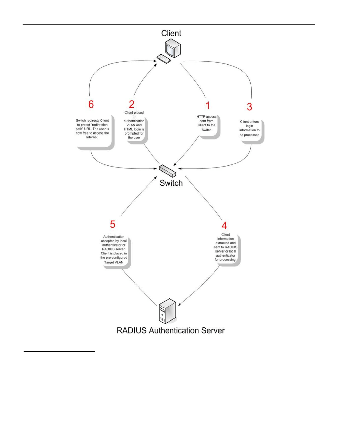
xStack® DGS-3420 Series Layer 2 Managed Stackable Gigabit Switch Web UI Reference Guide
306
Conditions and Limitations
1. If the client is utilizing DHCP to attain an IP address, the authentication VLAN must provide a DHCP server or
a DHCP relay function so that client may obtain an IP address.
2. Certain functions exist on the Switch that will filter HTTP packets, such as the Access Profile function. The user
needs to be very careful when setting filter functions for the target VLAN, so that these HTTP packets are not
denied by the Switch.
3. If a RADIUS server is to be used for authentication, the user must first establish a RADIUS Server with the
appropriate parameters, including the target VLAN, before enabling Web Authentication on the Switch.
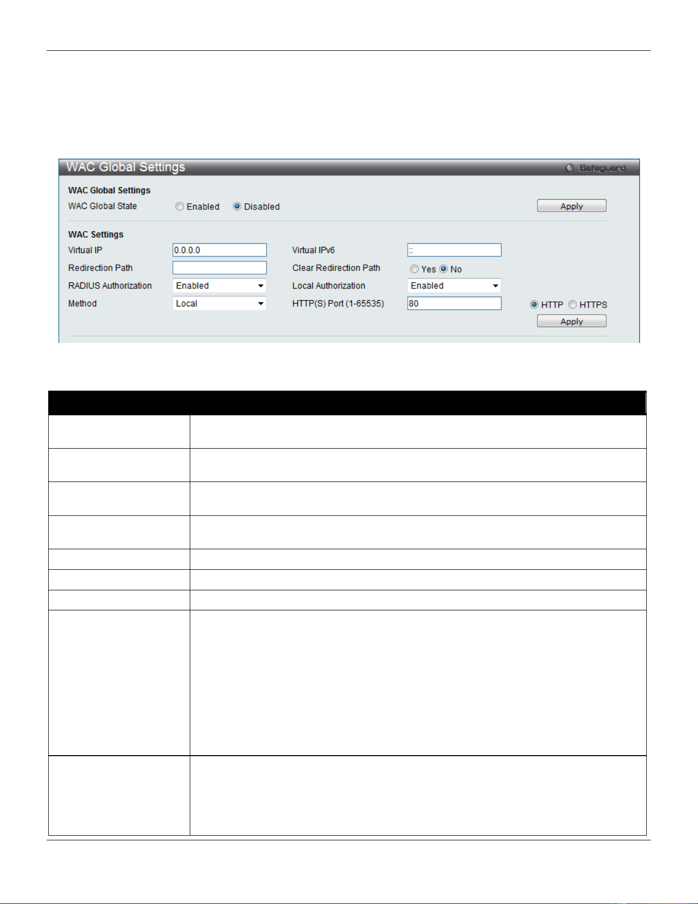
xStack® DGS-3420 Series Layer 2 Managed Stackable Gigabit Switch Web UI Reference Guide
307
WAC Global Settings
Users can configure the Switch for the Web-based access control function.
To view this window, click Security > Web-based Access Control (WAC) > WAC Global Settings as shown below:
Figure 8-36 WAC Global Settings window
The fields that can be configured are described below:
Parameter Description
WAC Global State
Use this selection menu to either enable or disable the Web Authentication on the
Switch.
Virtual IP
Enter a virtual IP address. This address is only used by WAC and is not known by any
other modules of the Switch.
Virtual IPv6
Enter a virtual IPv6 address. This address is only used by WAC and is not known by
any other modules of the Switch.
Redirection Path
Enter the URL of the website that authenticated users placed in the VLAN are directed
to once authenticated.
Clear Redirection Path
The user can enable or disable this option to clear the redirection path.
RADIUS Authorization
The user can enable or disable this option to enable RADIUS Authorization or not.
Local Authorization
The user can enable or disable this option to enable Local Authorization or not.
Method
Use this drop-down menu to choose the authenticator for Web-based Access Control.
The user may choose:
Local – Choose this parameter to use the local authentication method of the Switch as
the authenticating method for users trying to access the network via the switch. This is,
in fact, the username and password to access the Switch configured using the WAC
User Settings window seen below.
RADIUS – Choose this parameter to use a remote RADIUS server as the authenticating
method for users trying to access the network via the switch. This RADIUS server must
have already been pre-assigned by the administrator using the
Authentication RADIUS
Server Settings window.
HTTP(S) Port (1-65535) Enter a HTTP port number. Port 80 is the default.
HTTP – Specifies that the TCP port will run the WAC HTTP protocol. The default value
is 80. HTTP port cannot run at TCP port 443.
HTTPS – Specifies that the TCP port will run the WAC HTTPS protocol. The default
value is 443. HTTPS cannot run at TCP port 80.
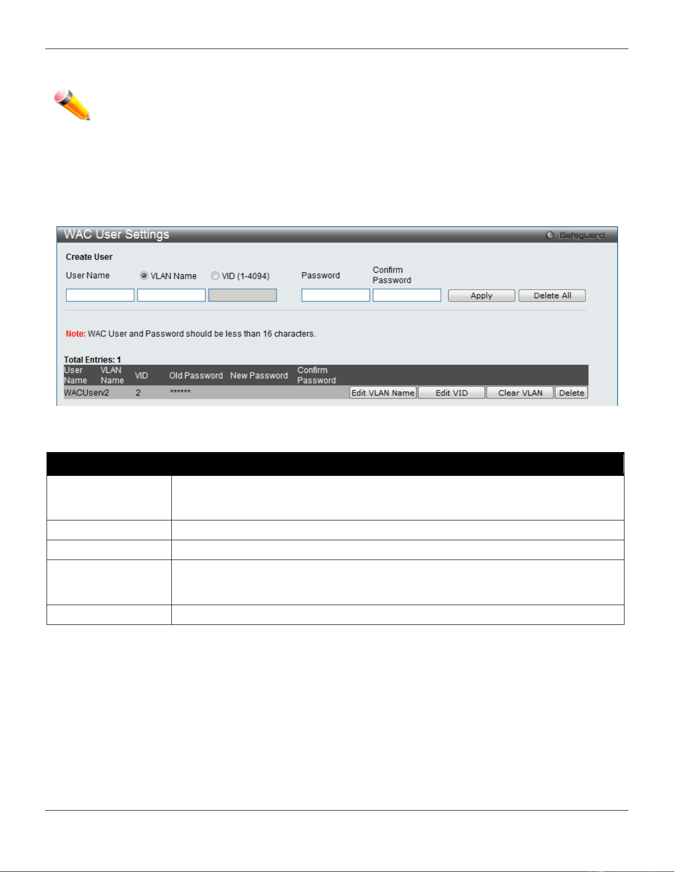
xStack® DGS-3420 Series Layer 2 Managed Stackable Gigabit Switch Web UI Reference Guide
308
Click the Apply button to accept the changes made for each individual section.
NOTE: A successful authentication should direct the client to the stated web page. If the client does not
reach this web page, yet does not receive a Fail! Message, the client will already be authenticated
and therefore should refresh the current browser window or attempt to open a different web page.
WAC User Settings
Users can view and set local database user accounts for Web authentication.
To view this window, click Security > Web-based Access Control (WAC) > WAC User Settings as shown below:
Figure 8-37 WAC User Settings window
The fields that can be configured are described below:
Parameter Description
User Name
Enter the user name of up to 15 alphanumeric characters of the guest wishing to access
the Web through this process. This field is for administrators who have selected Local as
their Web-based authenticator.
VLAN Name
Click the button and enter a VLAN Name in this field.
VID (1-4094)
Click the button and enter a VID in this field.
Password
Enter the password the administrator has chosen for the selected user. This field is case-
sensitive and must be a complete alphanumeric string. This field is for administrators who
have selected Local as their Web-based authenticator.
Confirm Password
Retype the password entered in the previous field.
Click the Apply button to accept the changes made.
Click the Delete All button to remove all the entries listed.
Click the Edit VLAN Name button to re-configure the specific entry’s VLAN Name.
Click the Edit VID button to re-configure the specific entry’s VLAN ID.
Click the Clear VLAN button to remove the VLAN information from the specific entry.
Click the Delete button to remove the specific entry.
WAC Port Settings
Users can view and set port configurations for Web authentication.
To view this window, click Security > Web-based Access Control (WAC) > WAC Port Settings as shown below:
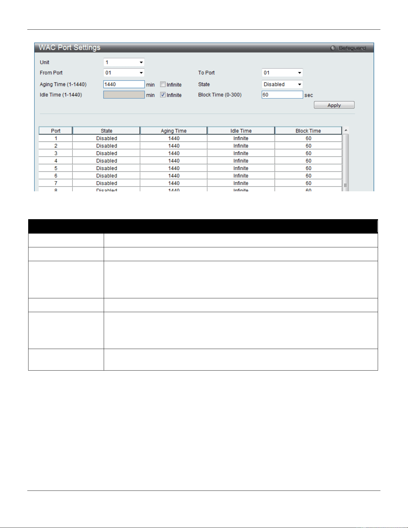
xStack® DGS-3420 Series Layer 2 Managed Stackable Gigabit Switch Web UI Reference Guide
309
Figure 8-38 WAC Port Settings window
The fields that can be configured are described below:
Parameter Description
Unit
Select the unit you wish to configure.
From Port / To Port
Use the drop-down menus to select a range of ports to be enabled as WAC ports.
Aging Time (1-1440)
This parameter specifies the time period during which an authenticated host will remain in
the authenticated state. Enter a value between 1and 1440 minutes. Tick the Infinite check
box to indicate the authenticated host will never age out on the port. The default value is
1440 minutes (24 hours).
State
Use this drop-down menu to enable the configured ports as WAC ports.
Idle Time (1-1440)
If there is no traffic during the Idle Time parameter, the host will be moved back to the
unauthenticated state. Enter a value between 1 and 1440 minutes. Tick the Infinite check
box to indicate the Idle state of the authenticated host on the port will never be checked.
The default value is Infinite.
Block Time (0-300)
This parameter is the period of time a host will be blocked if it fails to pass authentication.
Enter a value between 0 and 300 seconds. The default value is 60 seconds.
Click the Apply button to accept the changes made.
WAC Authentication State
Users can view and delete the hosts for Web authentication.
To view this window, click Security > Web-based Access Control (WAC) > WAC Authentication State as shown
below:
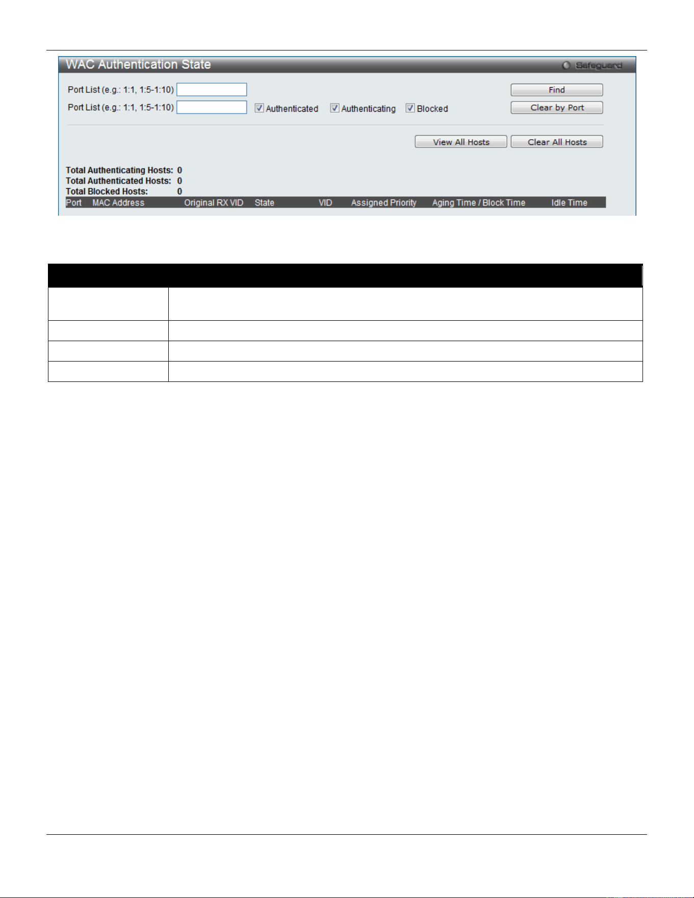
xStack® DGS-3420 Series Layer 2 Managed Stackable Gigabit Switch Web UI Reference Guide
310
Figure 8-39 WAC Authentication State window
The fields that can be configured are described below:
Parameter Description
Port List
Enter a port or range of ports, and tick the appropriate check box(s), Authenticated,
Authenticating, and Blocked.
Authenticated
Tick this check box to clear all authenticated users for a port.
Authenticating
Tick this check box to clear all authenticating users for a port.
Blocked
Tick this check box to clear all blocked users for a port.
Click the Find button to locate a specific entry based on the information entered.
Click the Clear by Port button to remove entry based on the port list entered.
Click the View All Hosts button to display all the existing entries.
Click the Clear All Hosts button to remove all the entries listed.
WAC Customize Page
This window is used to customize the authenticate page elements.
To view this window, click Security > Web-based Access Control (WAC) > WAC Customize Page as shown below:
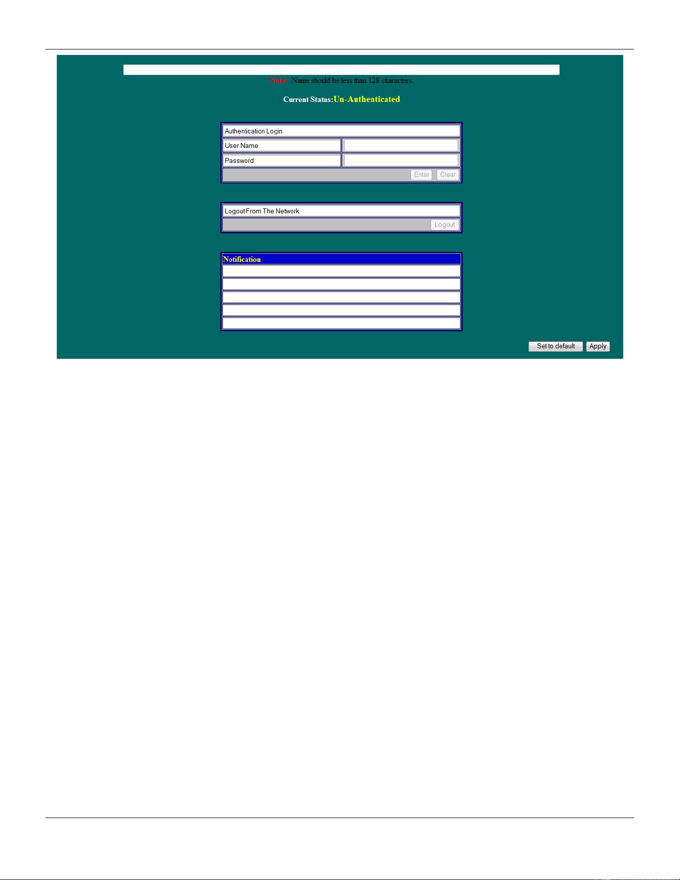
xStack® DGS-3420 Series Layer 2 Managed Stackable Gigabit Switch Web UI Reference Guide
311
Figure 8-40 WAC Customize Page window
Complete the WAC authentication information on this window to set the WAC page settings. Click the Apply button to
implement the changes made. Click the Set to default button to go back to the default settings of all elements. Click
the Edit button to re-configure the elements.
Japanese Web-based Access Control (JWAC)
JWAC Global Settings
This window is used to enable and configure Japanese Web-based Access Control on the Switch. JWAC and Web
Authentication are mutually exclusive functions. That is, they cannot be enabled at the same time. To use the JWAC
feature, computer users need to pass through two stages of authentication. The first stage is to do the authentication
with the quarantine server and the second stage is the authentication with the Switch. For the second stage, the
authentication is similar to Web Authentication, except that there is no port VLAN membership change by JWAC after a
host passes authentication. JWAC and WAC can share the same RADIUS server.
To view this window, click Security > Japanese Web-based Access Control (JWAC) > JWAC Global Settings as
shown below:
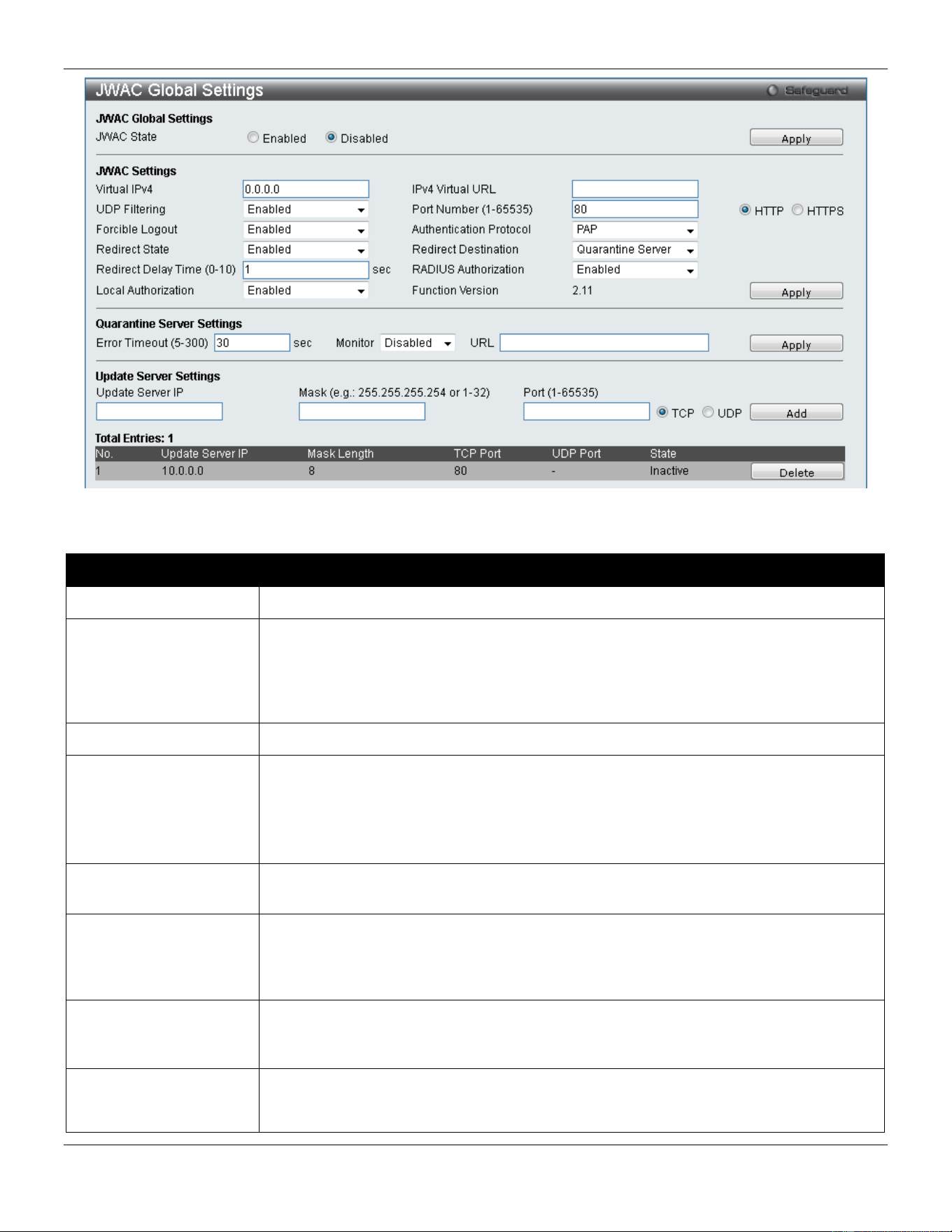
xStack® DGS-3420 Series Layer 2 Managed Stackable Gigabit Switch Web UI Reference Guide
312
Figure 8-41 JWAC Global Settings Window
The fields that can be configured are described below:
Parameter Description
JWAC State
Click the radio buttons to enable or disable JWAC on the Switch.
Virtual IPv4
Enter the JWAC Virtual IP address that is used to accept authentication requests from
an unauthenticated host. The Virtual IP address of JWAC is used to accept
authentication requests from an unauthenticated host. Only requests sent to this IP will
get a correct response.
NOTE: This IP does not respond to ARP requests or ICMP packets.
IPv4 Virtual URL
Enter the Virtual URL used.
UDP Filtering
Use the drop-down menu to enable or disable JWAC UDP Filtering. When UDP Filtering
is Enabled, all UDP and ICMP packets except DHCP and DNS packets from
unauthenticated hosts will be dropped.
A ping packet will pass through when the JWAC authenticating time is between 0 and
30.
Port Number (1-65535)
Enter the TCP port that the JWAC Switch listens to and uses to finish the authenticating
process.
Forcible Logout
Use the drop-down menu to enable or disable JWAC Forcible Logout. When Forcible
Logout is Enabled, a Ping packet from an authenticated host to the JWAC Switch with
TTL=1 will be regarded as a logout request, and the host will move back to the
unauthenticated state.
Authentication
Protocol
Use the drop-down menu to choose the RADIUS protocol used by JWAC to complete a
RADIUS authentication. The options include Local, EAP MD5, PAP, CHAP, MS CHAP,
and MS CHAPv2.
Redirect State
Use the drop-down menu to enable or disable JWAC Redirect. When the redirect
quarantine server is enabled, the unauthenticated host will be redirected to the
quarantine server when it tries to access a random URL. When the redirect JWAC login

xStack® DGS-3420 Series Layer 2 Managed Stackable Gigabit Switch Web UI Reference Guide
313
page is enabled, the unauthenticated host will be redirected to the JWAC login page in
the Switch to finish authentication. When redirect is disabled, only access to the
quarantine server and the JWAC login page from the unauthenticated host are allowed,
all other web access will be denied.
NOTE: When enabling redirect to the quarantine server, a quarantine server must be
configured first.
Redirect Destination
Use the drop-down menu to select the destination before an unauthenticated host is
redirected to either the Quarantine Server or the JWAC Login Page.
Redirect Delay Time (0-
10)
Enter the Delay Time before an unauthenticated host is redirected to the Quarantine
Server or JWAC Login Page. Enter a value between 0 and 10 seconds. A value of 0
indicates no delay in the redirect.
RADIUS Authorization
Use the drop-down menu to enable or disable RADIUS Authorization.
Local Authorization
Use the drop-down menu to enable or disable Local Authorization.
Error Timeout (5-300)
Enter the time in second for the Quarantine Server Error Timeout. When the Quarantine
Server Monitor is enabled, the JWAC Switch will periodically check if the Quarantine
works okay. If the Switch does not receive any response from the Quarantine Server
during the configured Error Timeout, the Switch then regards it as not working properly.
Enter a value between 5 and 300 seconds.
Monitor
Use the drop-down menu to enable or disable the JWAC Quarantine Server Monitor.
When Enabled, the JWAC Switch will monitor the Quarantine Server to ensure the
server is okay. If the Switch detects no Quarantine Server, it will redirect all
unauthenticated HTTP access attempts to the JWAC Login Page forcibly if the Redirect
is enabled and the Redirect Destination is configured to be a Quarantine Server.
URL
Enter the JWAC Quarantine Server URL. If the Redirect is enabled and the Redirect
Destination is the Quarantine Server, when an unauthenticated host sends the HTTP
request packets to a random Web server, the Switch will handle this HTTP packet and
send back a message to the host to allow it access to the Quarantine Server with the
configured URL. When a computer is connected to the specified URL, the quarantine
server will request the computer user to input the user name and password to complete
the authentication process.
Update Server IP
Enter the Update Server IP address.
Mask
Enter the Server IP net mask.
Port (1-65535) Enter the port number used by the Update Server. Tick the TCP or UDP options to
specifies that this port uses the TCP or UDP protocol.
Click the Apply button to accept the changes made for each individual section.
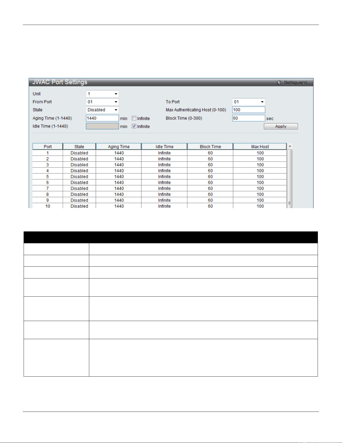
xStack® DGS-3420 Series Layer 2 Managed Stackable Gigabit Switch Web UI Reference Guide
314
JWAC Port Settings
This window is used to configure JWAC port settings for the Switch.
To view this window, click Security > Japanese Web-based Access Control (JWAC) > JWAC Port Settings as
shown below:
Figure 8-42 JWAC Port Settings Window
The fields that can be configured are described below:
Parameter Description
Unit
Select the unit you wish to configure.
From Port / To Port
Use the drop-down menus to select a range of ports to be enabled as JWAC ports.
State
Use this drop-down menu to enable the configured ports as JWAC ports.
Max Authenticating
Host (0-100)
Enter the maximum number of host process authentication attempts allowed on each port
at the same time. The default value is 100.
Aging Time (1-1440)
Enter the time period during which an authenticated host will remain in the authenticated
state. Tick the Infinite check box to never age out the authenticated host on the port. The
default value is 1440.
Block Time (0-300)
Enter the period of time that a host will be blocked if it fails to pass authentication. The
default value is 60.
Idle Time (1-1440)
If there is no traffic during the Idle Time parameter, the host will be moved back to the
unauthenticated state. The default value is Infinite. To change this value, un-tick the
Infinite check box and enter a value between 1 and 1440 minute(s). Tick the Infinite
check box to indicate the Idle state of the authenticated host on the port will never be
checked.
Click the Apply button to accept the changes made.
JWAC User Settings
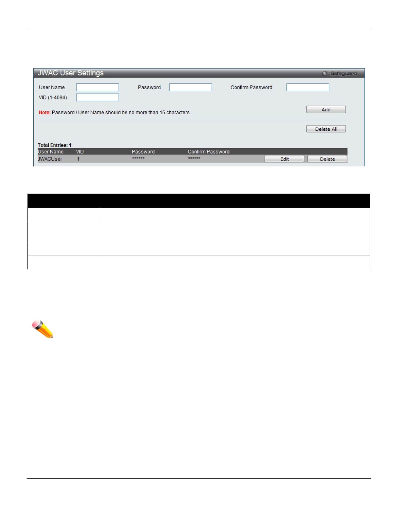
xStack® DGS-3420 Series Layer 2 Managed Stackable Gigabit Switch Web UI Reference Guide
315
This window is used to configure a JWAC user of the switch’s local database.
To view this window, click Security > Japanese Web-based Access Control (JWAC) > JWAC User Settings as
shown below:
Figure 8-43 JWAC User Settings Window
The fields that can be configured are described below:
Parameter Description
User Name
Enter a username of up to 15 alphanumeric characters.
Password
Enter the password the administrator has chosen for the selected user. This field is case-
sensitive and must be a complete alphanumeric string.
Confirm Password
Retype the password entered in the previous field.
VID(1-4094)
Enter a VLAN ID number between 1 and 4094.
Click the Add button to add a new entry based on the information entered.
Click the Delete All button to remove all the entries listed.
Click the Edit button to re-configure the specific entry.
Click the Delete button to remove the specific entry.
NOTE: The Username and Password values should be less than 16 characters.
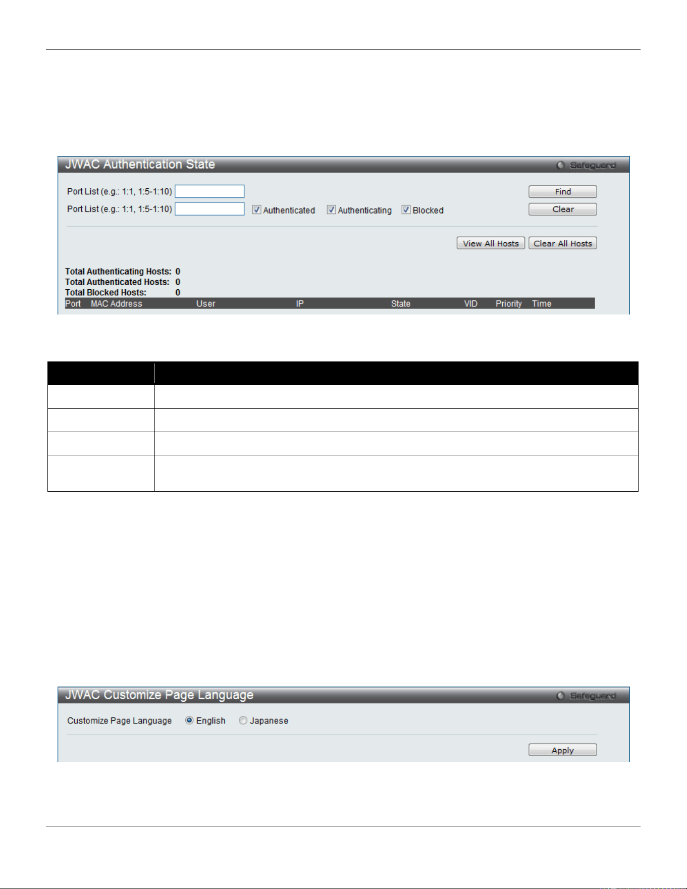
xStack® DGS-3420 Series Layer 2 Managed Stackable Gigabit Switch Web UI Reference Guide
316
JWAC Authentication State
This window is used to display Japanese Web-based Access Control Host Table information.
To view this window, click Security > Japanese Web-based Access Control (JWAC) > JWAC Authentication State
as shown below:
Figure 8-44 JWAC Authentication State Window
The fields that can be configured are described below:
Parameter Description
Port List
Enter a port or range of ports.
Authenticated
Tick this check box to only clear authenticated client hosts.
Authenticating
Tick this check box to only clear client hosts in the authenticating process.
Blocked
Tick this check box to only clear client hosts being temporarily blocked because of the failure
of authentication.
Click the Find button to locate a specific entry based on the information entered.
Click the Clear button to remove entry based on the port list entered.
Click the View All Hosts button to display all the existing entries.
Click the Clear All Hosts button to remove all the entries listed.
JWAC Customize Page Language
Users can configure JWAC page and language settings for the Switch. The current firmware supports either English or
Japanese.
To view this window, click Security > Japanese Web-based Access Control (JWAC) > JWAC Customize Page
Language as shown below:
Figure 8-45 JWAC Customize Page Language Window
The fields that can be configured are described below:
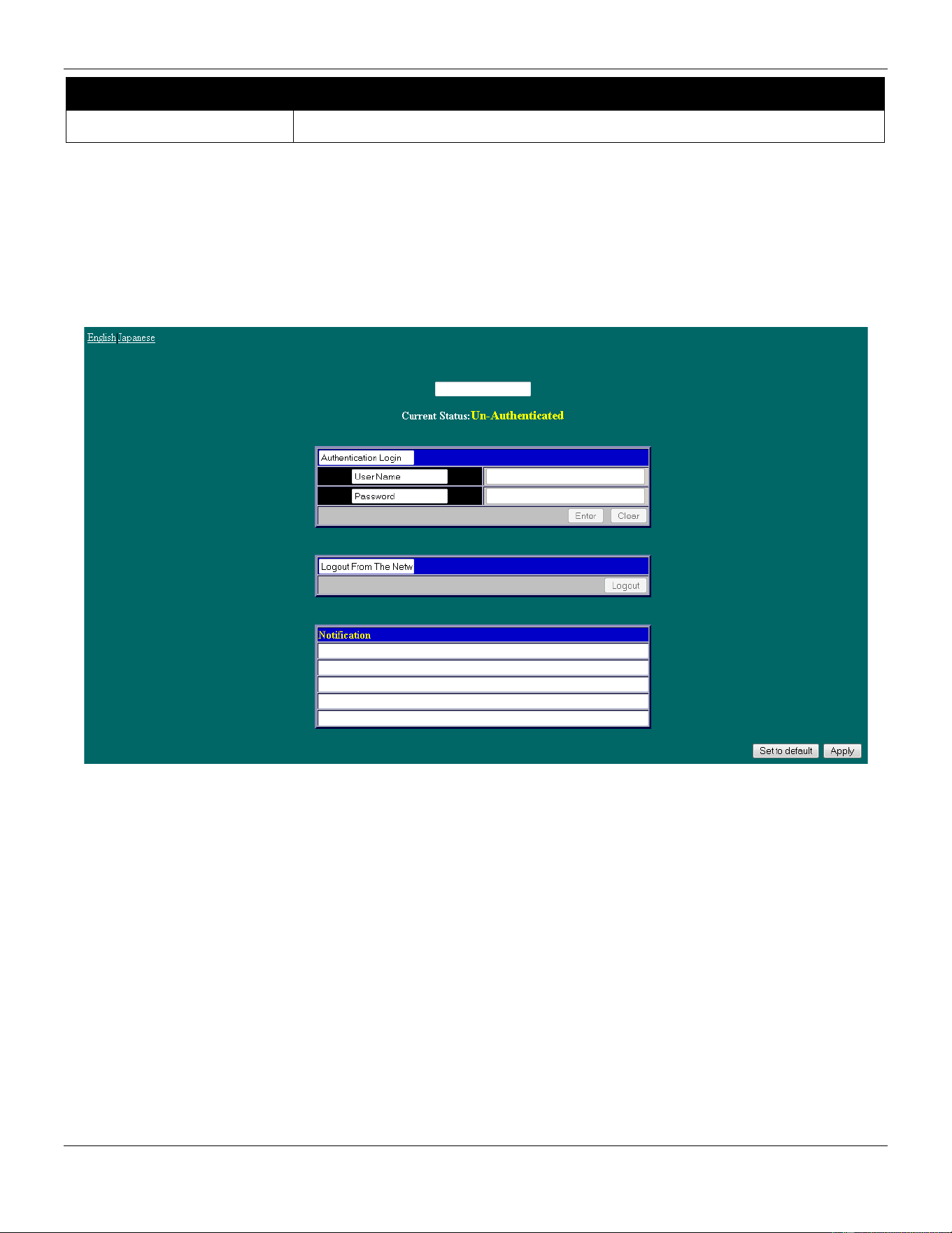
xStack® DGS-3420 Series Layer 2 Managed Stackable Gigabit Switch Web UI Reference Guide
317
Parameter Description
Customize Page Language
Click the radio buttons to select English or Japanese.
Click the Apply button to accept the changes made.
JWAC Customize Page
This window is used to configure JWAC page settings for the Switch.
To view this window, click Security > Japanese Web-based Access Control (JWAC) > JWAC Customize Page as
shown below:
Figure 8-46 English JWAC Login Window
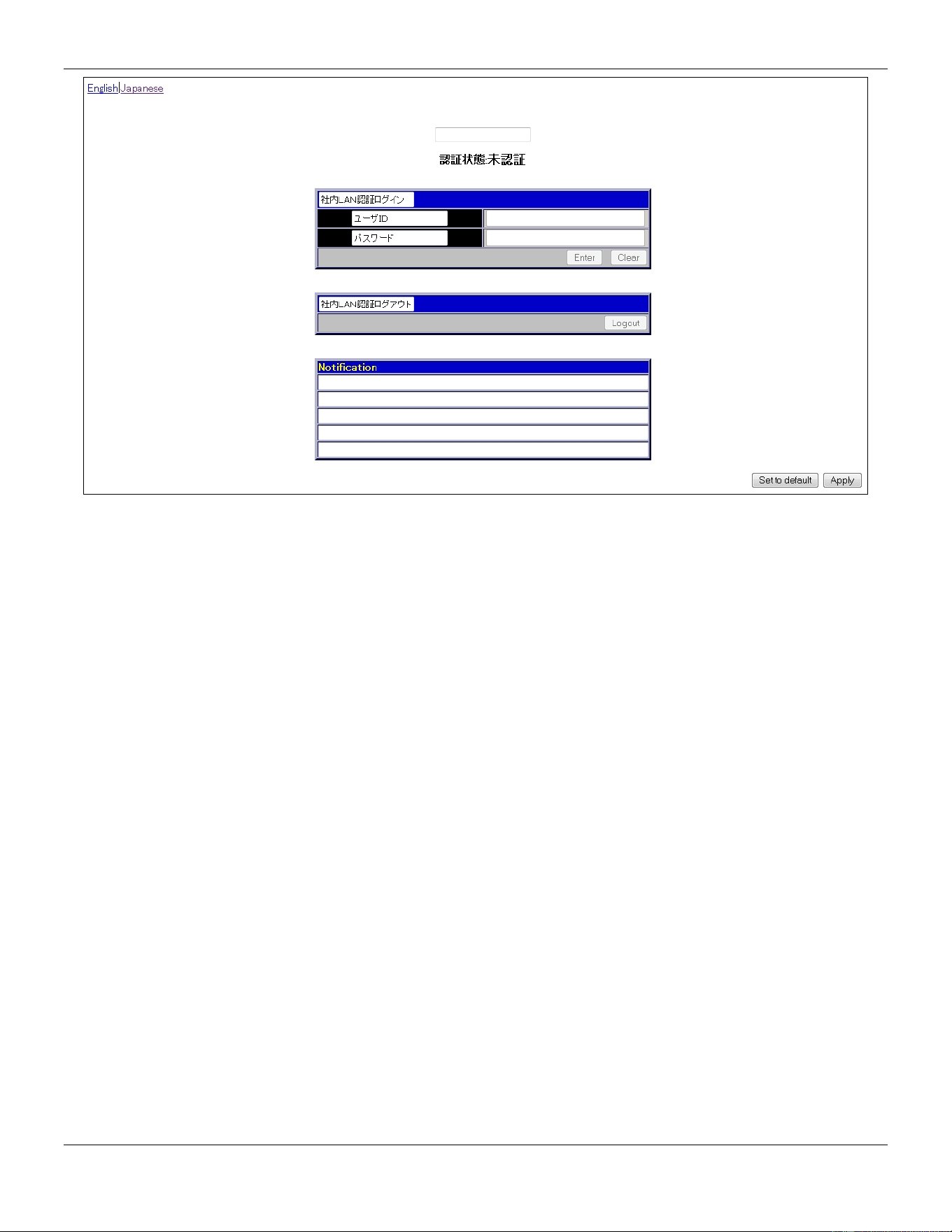
xStack® DGS-3420 Series Layer 2 Managed Stackable Gigabit Switch Web UI Reference Guide
318
Figure 8-47 Japanese JWAC Login Window
Complete the JWAC authentication information on this window to set the JWAC page settings. Enter a name for the
Authentication in the first field and then click the Apply button. Next, enter a User Name and a Password and then
click the Enter button.
Compound Authentication
Compound Authentication settings allows for multiple authentication to be supported on the Switch.
Compound Authentication Settings
This window is used to configure Authorization Network State Settings and compound authentication methods for a
port or ports on the Switch.
To view this window, click Security > Compound Authentication > Compound Authentication Settings as shown
below:
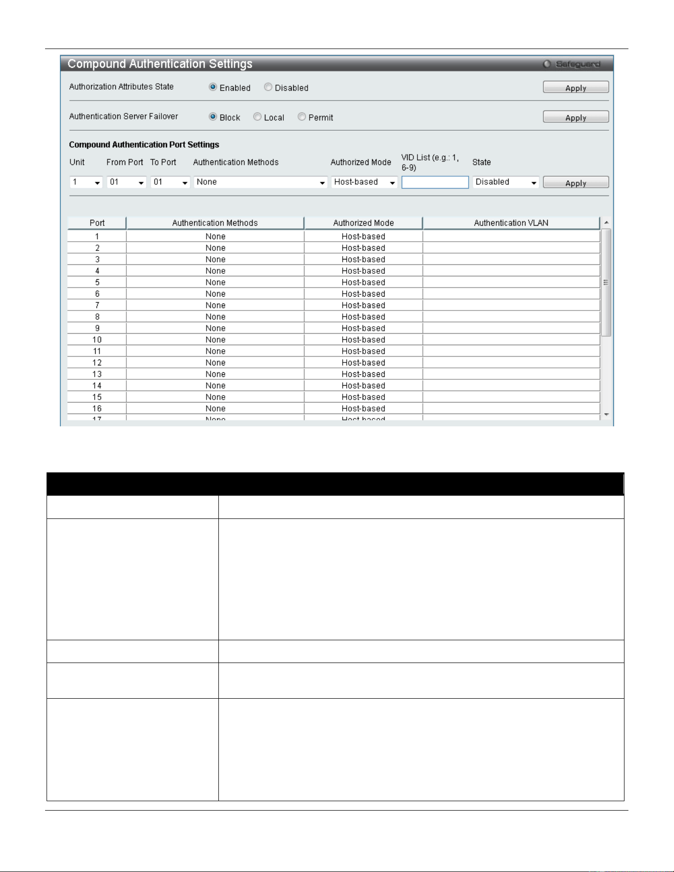
xStack® DGS-3420 Series Layer 2 Managed Stackable Gigabit Switch Web UI Reference Guide
319
Figure 8-48 Compound Authentication Settings window
The fields that can be configured are described below:
Parameter Description
Authorization Attributes State
Click the radio buttons to enable of disable the Authorization Attributes State.
Authentication Server
Failover
Click the radio buttons to configure the authentication server failover function.
Block (default setting) - The client is always regarded as un-authenticated.
Local - The switch will resort to using the local database to authenticate the
client. If the client fails on local authentication, the client is regarded as un-
authenticated, otherwise, it authenticated.
Permit - The client is always regarded as authenticated. If guest VLAN is
enabled, clients will stay on the guest VLAN, otherwise, they will stay on the
original VLAN.
Unit
Select the unit you wish to configure.
From Port / To Port
Use the drop-down menus to select a range of ports to be enabled as compound
authentication ports.
Authentication Methods The compound authentication method options include: None, Any (MAC,
802.1X, JWAC or WAC), 802.1X+IMPB, IMPB+JWAC, IMPB+WAC, and
MAC+IMPB.
None - all compound authentication methods are disabled.
Any (MAC, 802.1X, JWAC or WAC) - if any of the authentication methods pass,
then access will be granted. In this mode, MAC, 802.1X, JWAC and WAC can
be enabled on a port at the same time. In Any (MAC, 802.1X, JWAC or WAC)
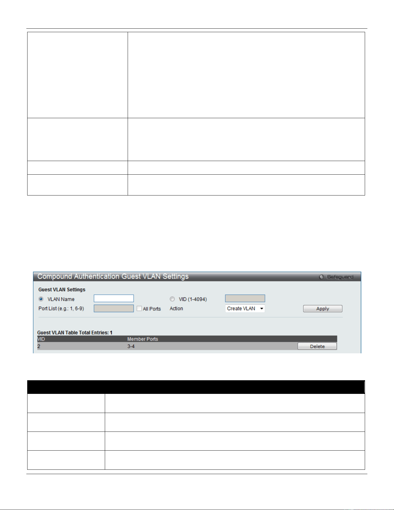
xStack® DGS-3420 Series Layer 2 Managed Stackable Gigabit Switch Web UI Reference Guide
320
mode, whether an individual security module is active on a port depends on its
system state.
802.1X+IMPB - 802.1X will be verified first, and then IMPB will be verified. Both
authentication methods need to be passed.
IMPB+JWAC – JWAC will be verified first, and then IMPB will be verified. Both
authentication methods need to be passed.
IMPB+WAC - WAC will be verified first, and then IMPB will be verified. Both
authentication methods need to be passed.
MAC+IMPB - MAC will be verified first, and then IMPB will be verified. Both
authentication methods need to be passed.
Authorized Mode Toggle between Host-based and Port-based. When Port-based is selected, if
one of the attached hosts passes the authentication, all hosts on the same port
will be granted access to the network. If the user fails the authorization, this port
will keep trying the next authentication method. When Host-based is selected,
users are authenticated individually.
VID List
Enter a list of VLAN ID.
State
Use the drop-down menu to assign or remove the specified VID list as
authentication VLAN(s).
Click the Apply button to accept the changes made for each individual section.
Compound Authentication Guest VLAN Settings
This window is used to assign ports to or remove ports from a guest VLAN.
To view this window, click Security > Compound Authentication > Compound Authentication Guest VLAN
Settings as shown below:
Figure 8-49 Compound Authentication Guest VLAN Settings window
The fields that can be configured are described below:
Parameter Description
VLAN Name
Click the button and assign a VLAN as a Guest VLAN. The VLAN must be an existing
static VLAN.
VID (1-4094)
Click the button and assign a VLAN ID for a Guest VLAN. The VLAN must be an existing
static VLAN before this VID can be configured.
Port List The list of ports to be configured. Alternatively, tick the All Ports check box to set every
port at once.
Action Use the drop-down menu to choose the desired operation: Create VLAN, Add Ports, or
Delete Ports.
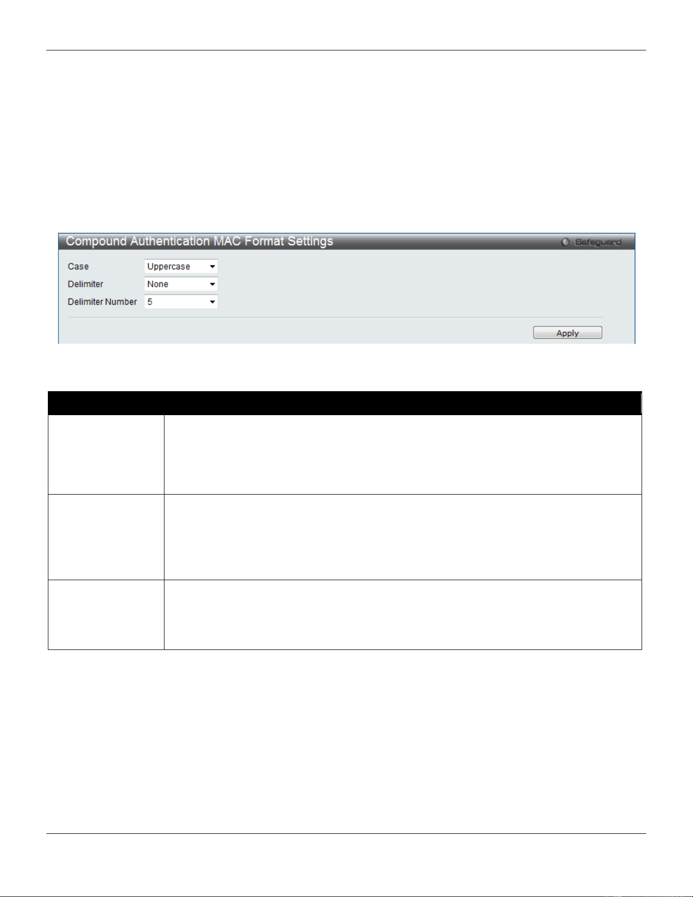
xStack® DGS-3420 Series Layer 2 Managed Stackable Gigabit Switch Web UI Reference Guide
321
Click the Apply button to accept the changes made.
Click the Delete button to remove the specific entry.
Once properly configured, the Guest VLAN and associated ports will be listed in the lower part of the window.
Compound Authentication MAC Format Settings
This window is used to set the MAC address format that will be used for authentication username via the RADIUS
server.
To view this window, click Security > Compound Authentication > Compound Authentication MAC Format
Settings as shown below:
Figure 8-50 Compound Authentication MAC Format Settings window
The fields that can be configured are described below:
Parameter Description
Case
Use the drop-down menu to select the format for the RADIUS authentication username.
Lowerercase - Use lowercase format, the RADIUS authentication username will be
formatted as: aa-bb-cc-dd-ee-ff.
Uppercase - Use uppercase format, the RADIUS authentication username will be formatted
as: AA-BB-CC-DD-EE-FF.
Delimiter
Use the drop-down menu to select the delimiter format.
Hyphen - Use "-" as delimiter, the format is: AA-BB-CC-DD-EE-FF.
Colon - Use ":" as delimiter, the format is: AA:BB:CC:DD:EE:FF.
Dot - Use "." as delimiter, the format is: AA.BB.CC.DD.EE.FF.
None – Do not use any delimiter, the format is: AABBCCDDEEFF.
Delimiter Number
Use the drop-down menu to select the delimiter number.
1 - Single delimiter, the format is: AABBCC.DDEEFF.
2 - Double delimiter, the format is: AABB.CCDD.EEFF.
5 - Multiple delimiter, the format is: AA.BB.CC.DD.EE.FF.
Click the Apply button to accept the changes made.
IGMP Access Control Settings
Users can set IGMP authentication, otherwise known as IGMP access control, on individual ports on the Switch. When
the Authentication State is Enabled, and the Switch receives an IGMP join request, the Switch will send the access
request to the RADIUS server to do the authentication.
IGMP authentication processes IGMP reports as follows: When a host sends a join message for the interested
multicast group, the Switch has to do authentication before learning the multicast group/port. The Switch sends an
Access-Request to an authentication server and the information including host MAC, switch port number, switch IP,
and multicast group IP. When the Access-Accept is answered from the authentication server, the Switch learns the
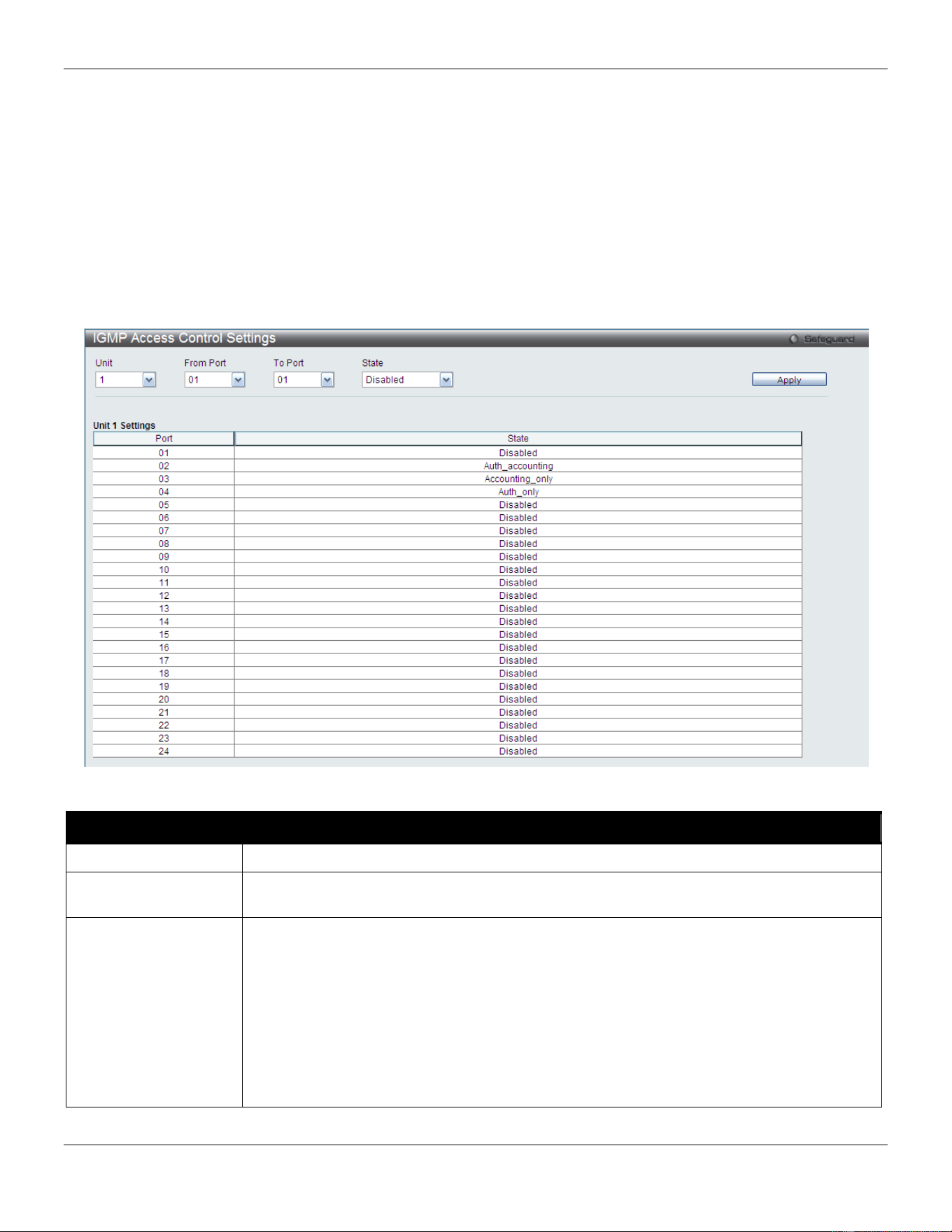
xStack® DGS-3420 Series Layer 2 Managed Stackable Gigabit Switch Web UI Reference Guide
322
multicast group/port. When the Access-Reject is answered from the authentication server, the Switch won’t learn the
multicast group/port and won’t process the packet further. The entry (host MAC, switch port number, and multicast
group IP) is put in the “authentication failed list.” When there is no answer from the authentication server after T1 time,
the Switch resends the Access-Request to the server. If the Switch doesn’t receive a response after N1 times, the
result is denied and the entry (host MAC, switch port number, multicast group IP) is put in the “authentication failed
list.” In general case, when the multicast group/port is already learned by the switch, it won’t do the authentication
again. It only processes the packet as standard.
IGMP authentication processes IGMP leaves as follows: When the host sends leave message for the specific multicast
group, the Switch follows the standard procedure for leaving a group and then sends an Accounting-Request to the
accounting server for notification. If there is no answer from the accounting server after T2 time, the Switch resends the
Accounting-Request to the server. The maximum number of retry times is N2.
To view this window, click Security > IGMP Access Control Settings as shown below:
The fields that can be configured are described below:
Parameter Description
Unit
Select the unit you want to configure.
From Port / To Port
Use the drop-down menus to select a range of ports to be enabled as compound
authentication ports.
State
Use the drop-down menu to configure the IGMP authentication status. If no parameter is
chosen, Auth_accounting will be selected. This is for compatible application.
Disable - Disables both the authentication and accounting function on the specified port.
Auth_accounting - After the client authenticated, the accounting message will be sent to
the RADIUS.
Auth_only - After the client authenticated, the accounting message will not be sent to the
RADIUS.
Accounting_only - Authentication is not needed. If the client joins a group, the
accounting message will be sent to the RADIUS.
Click the Apply button to accept the changes made.
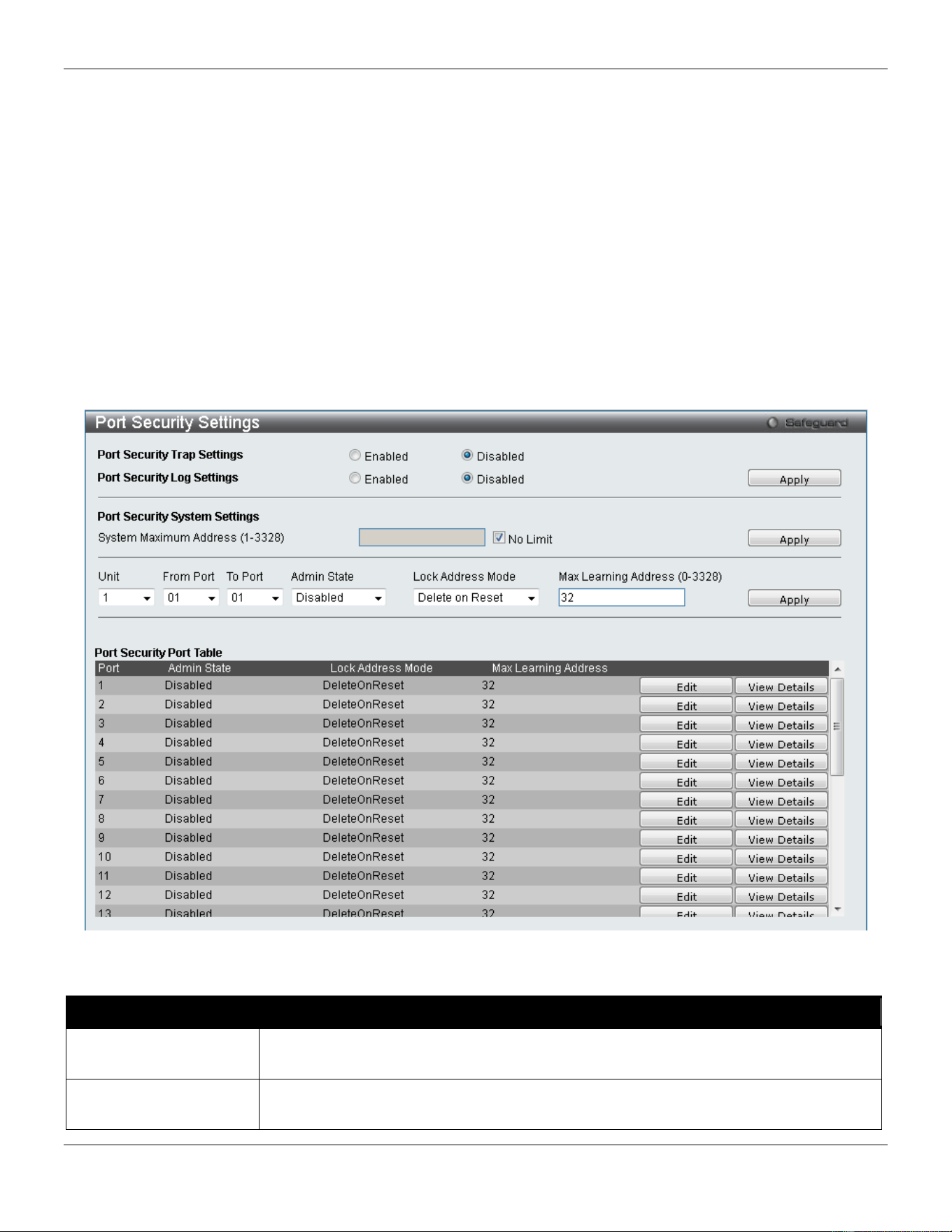
xStack® DGS-3420 Series Layer 2 Managed Stackable Gigabit Switch Web UI Reference Guide
323
Port Security
Port Security Settings
A given port’s (or a range of ports') dynamic MAC address learning can be locked such that the current source MAC
addresses entered into the MAC address forwarding table cannot be changed once the port lock is enabled. The port
can be locked by changing the Admin State drop-down menu to Enabled and clicking Apply.
Port Security is a security feature that prevents unauthorized computers (with source MAC addresses) unknown to the
Switch prior to locking the port (or ports) from connecting to the Switch's locked ports and gaining access to the
network.
To view this window, click Security > Port Security > Port Security Settings as shown below:
Figure 8-51 Port Security Settings window
The fields that can be configured are described below:
Parameter Description
Port Security Trap
Settings
Use the radio button to enable or disable Port Security Traps on the Switch.
Port Security Log
Settings
Use the radio button to enable or disable Port Security Logs on the Switch.
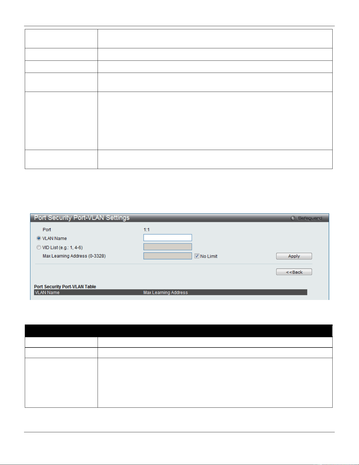
xStack® DGS-3420 Series Layer 2 Managed Stackable Gigabit Switch Web UI Reference Guide
324
System Maximum
Address (1-3328)
Enter the system maximum address.
Unit
Select the unit you want to configure.
From Port / To Port
Use the drop-down menus to select a range of ports to configure.
Admin State
Use the drop-down menu to enable or disable Port Security (locked MAC address table
for the selected ports).
Lock Address Mode
This drop-down menu allows the option of how the MAC address table locking will be
implemented on the Switch, for the selected group of ports. The options are:
Permanent – The locked addresses will never age out unless users manually delete the
entries, reboot or reset the Switch.
DeleteOnTimeout – The locked addresses will age out after the aging timer expires.
DeleteOnReset – The locked addresses will not age out until the Switch has been reset
or rebooted.
Max Learning Address
(0-3328)
Specify the maximum value of port security entries that can be learned on this port.
Click the Apply button to accept the changes made for each individual section.
Click the Edit button to re-configure the specific entry.
Click the View Detail button to display the information of the specific entry.
Click the View Detail button to see the following window.
Figure 8-52 Port Security Port-VLAN Settings window
The fields that can be configured are described below:
Parameter Description
VLAN Name
Click the radio button and enter a VLAN name.
VID List
Click the radio button and enter a list of VLAN ID.
Max Learning Address
(0-3328)
Enter the maximum number of port security entries that can be learned by this VLAN.
If this parameter is set to 0, it means that no user can be authorized on this VLAN.
If the setting is lower than the number of current learned entries on the VLAN, the
command will be rejected. Tick the No Limit check box to have unlimited number of
port security entries that can be learned by a specific VLAN.
The default value is No Limit.
Click the Apply button to accept the changes made.
Click the <<Back button to discard the changes made and return to the previous page.
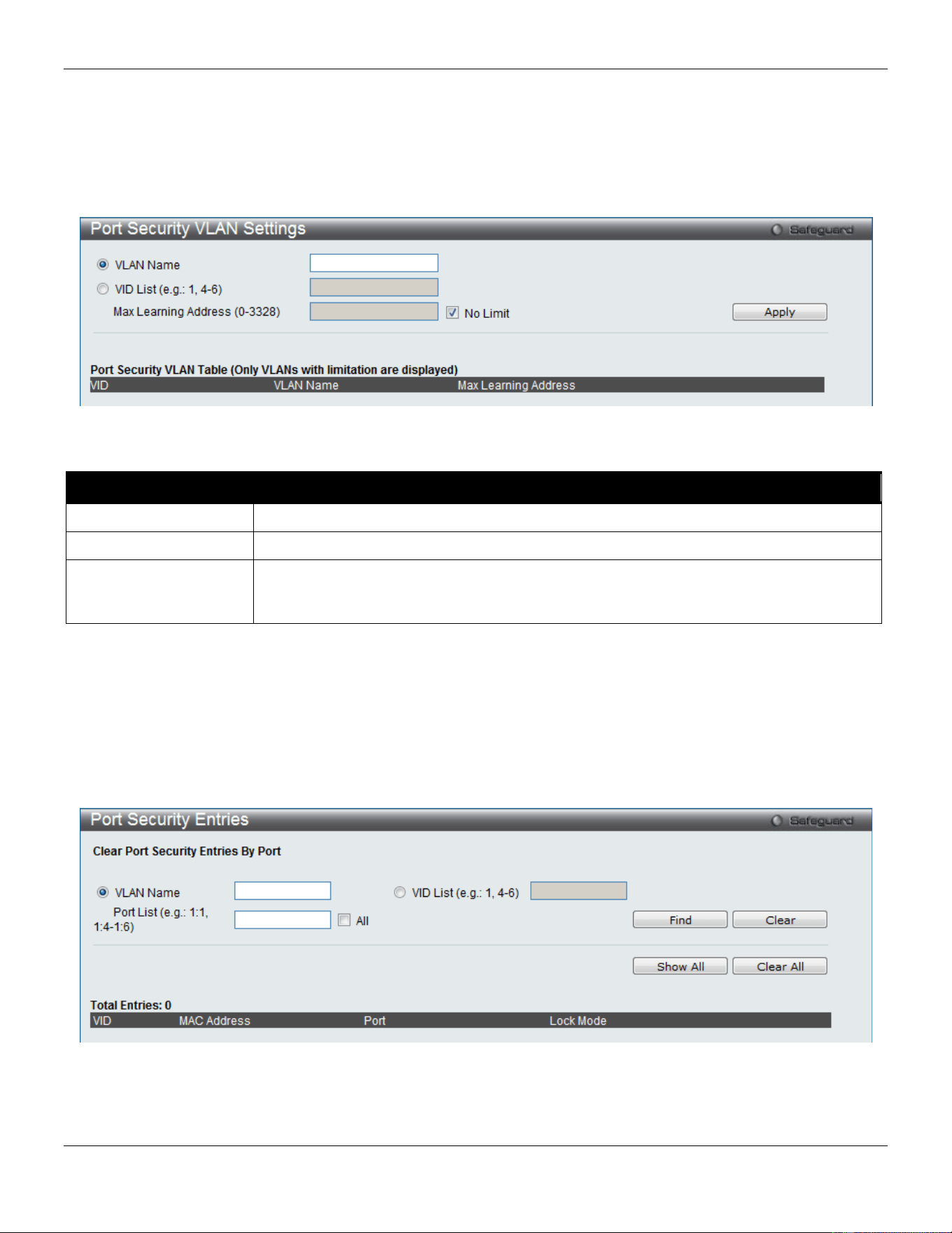
xStack® DGS-3420 Series Layer 2 Managed Stackable Gigabit Switch Web UI Reference Guide
325
Port Security VLAN Settings
This window is used to configure the maximum number of port-security entries that can be learned on a specific VLAN.
To view this window, click Security > Port Security > Port Security VLAN Settings as shown below:
Figure 8-53 Port Security VLAN Settings window
The fields that can be configured are described below:
Parameter Description
VLAN Name
Click the radio button and enter the VLAN Name.
VID List
Click the radio button and enter a list of the VLAN ID.
Max Learning Address
(0-3328)
Enter the maximum number of port-security entries that can be learned by this VLAN.
Tick the No Limit check box to have unlimited number of port-security entries that can
be learned by this VLAN.
Click the Apply button to accept the changes made.
Port Security Entries
This window is used to remove an entry from the port security entries learned by the Switch and entered into the
forwarding database.
To view this window, click Security > Port Security > Port Security Entries as shown below:
Figure 8-54 Port Security Entries window
The fields that can be configured or displayed are described below:
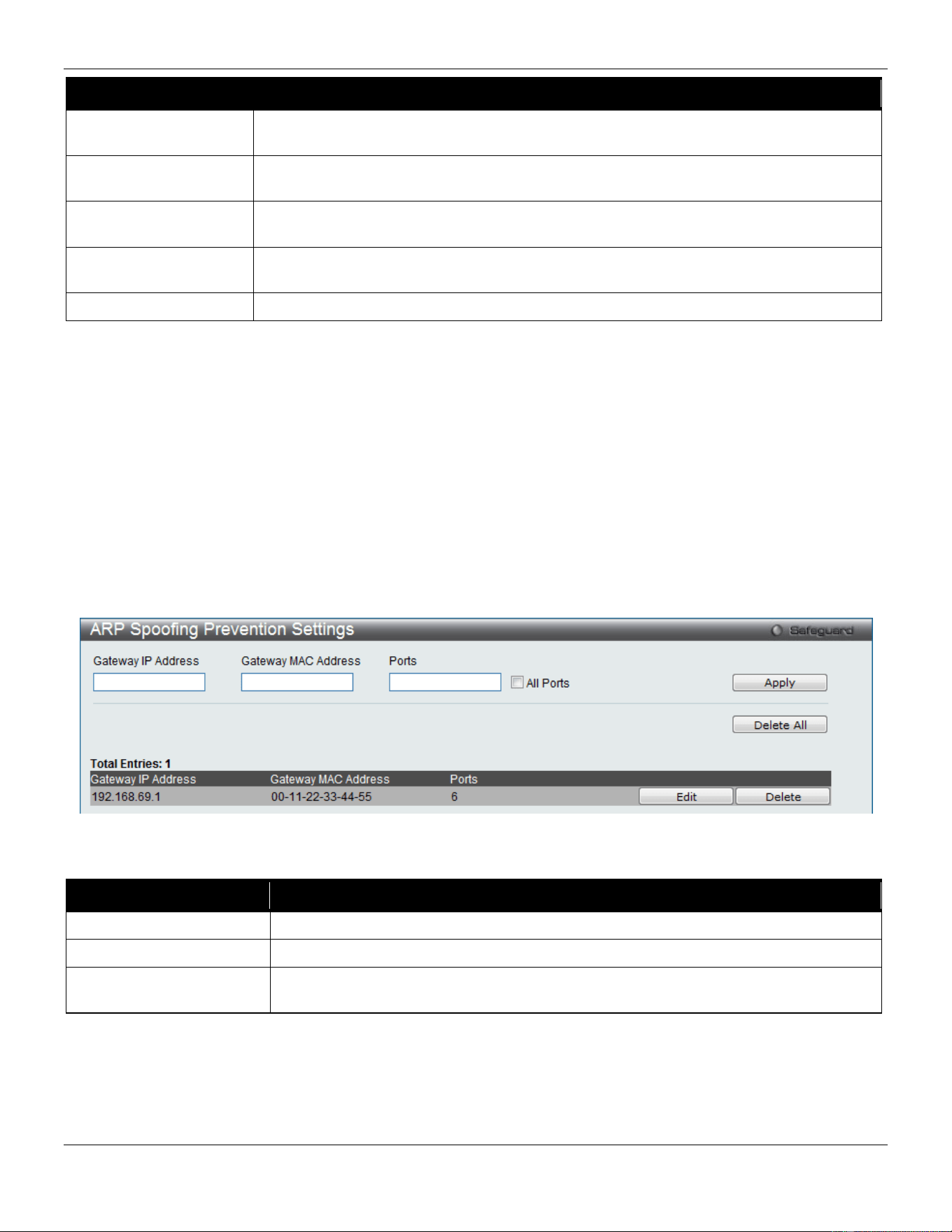
xStack® DGS-3420 Series Layer 2 Managed Stackable Gigabit Switch Web UI Reference Guide
326
Parameter Description
VLAN Name
The VLAN Name of the entry in the forwarding database table that has been
permanently learned by the Switch.
VID List
The VLAN ID of the entry in the forwarding database table that has been permanently
learned by the Switch.
Port List Enter the port number or list here to be used for the port security entry search. When All
is selected, all the ports configured will be displayed.
MAC Address
The MAC address of the entry in the forwarding database table that has been
permanently learned by the Switch.
Lock Mode
The type of MAC address in the forwarding database table.
Click the Find button to locate a specific entry based on the information entered.
Click the Clear button to clear all the entries based on the information entered.
Click the Show All button to display all the existing entries.
Click the Clear All button to remove all the entries listed.
Click the Delete button to remove the specific entry.
ARP Spoofing Prevention Settings
The user can configure the spoofing prevention entry to prevent spoofing of MAC for the protected gateway. When an
entry is created, those ARP packets whose sender IP matches the gateway IP of an entry, but either its sender MAC
field or source MAC field does not match the gateway MAC of the entry will be dropped by the system.
To view this window, click Security > ARP Spoofing Prevention Settings as shown below:
Figure 8-55 ARP Spoofing Prevention Settings window
The fields that can be configured are described below:
Parameter Description
Gateway IP Address
Enter the gateway IP address to help prevent ARP Spoofing.
Gateway MAC Address
Enter the gateway MAC address to help prevent ARP Spoofing.
Ports Enter the port numbers that this feature applies to. Alternatively the user can select All
Ports to apply this feature to all the ports of the switch.
Click the Apply button to accept the changes made.
Click the Delete All button to remove all the entries listed.
Click the Edit button to re-configure the specific entry.
Click the Delete button to remove the specific entry.
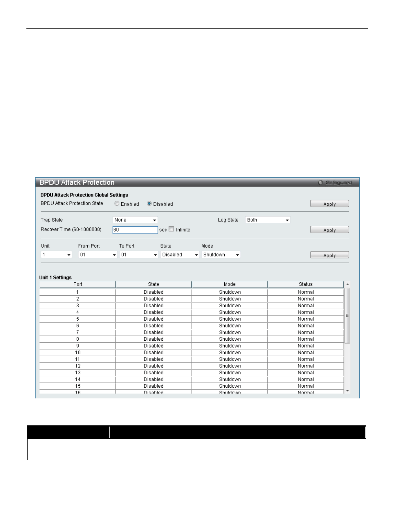
xStack® DGS-3420 Series Layer 2 Managed Stackable Gigabit Switch Web UI Reference Guide
327
BPDU Attack Protection
This page is used to configure the BPDU protection function for the ports on the switch. In generally, there are two
states in BPDU protection function. One is normal state, and another is under attack state. The under attack state have
three modes: drop, block, and shutdown. A BPDU protection enabled port will enter an under attack state when it
receives one STP BPDU packet. And it will take action based on the configuration. Thus, BPDU protection can only be
enabled on the STP-disabled port.
BPDU protection has a higher priority than the FBPDU setting configured by configure STP command in the
determination of BPDU handling. That is, when FBPDU is configured to forward STP BPDU but BPDU protection is
enabled, then the port will not forward STP BPDU.
BPDU protection also has a higher priority than the BPDU tunnel port setting in determination of BPDU handling. That
is, when a port is configured as BPDU tunnel port for STP, it will forward STP BPDU. But if the port is BPDU protection
enabled. Then the port will not forward STP BPDU.
To view this window, click Security > BPDU Attack Protection as shown below:
Figure 8-56 BPDU Attack Protection window
The fields that can be configured are described below:
Parameter Description
BPDU Attack Protection
State
Click the radio buttons to enable or disable the BPDU Attack Protection state.

xStack® DGS-3420 Series Layer 2 Managed Stackable Gigabit Switch Web UI Reference Guide
328
Trap State Specify when a trap will be sent. Options to choose from are None, Attack Detected,
Attack Cleared or Both.
Log State Specify when a log entry will be sent. Options to choose from are None, Attack
Detected, Attack Cleared or Both.
Recover Time (60-
1000000)
Enter the BPDU protection Auto-Recovery timer. The default value of the recovery
timer is 60. Tick the Infinite check box for not auto recovering.
Unit
Select the unit you wish to configure.
From Port / To Port
Select a range of ports to use for this configuration.
State
Use the drop-down menu to enable or disable the protection mode for a specific port.
Mode
Specify the BPDU protection mode. The default mode is shutdown.
Drop – Drop all received BPDU packets when the port enters under attack state.
Block – Drop all packets (include BPDU and normal packets) when the port enters
under attack state.
Shutdown – Shut down the port when the port enters under attack state.
Click the Apply button to accept the changes made for each individual section.
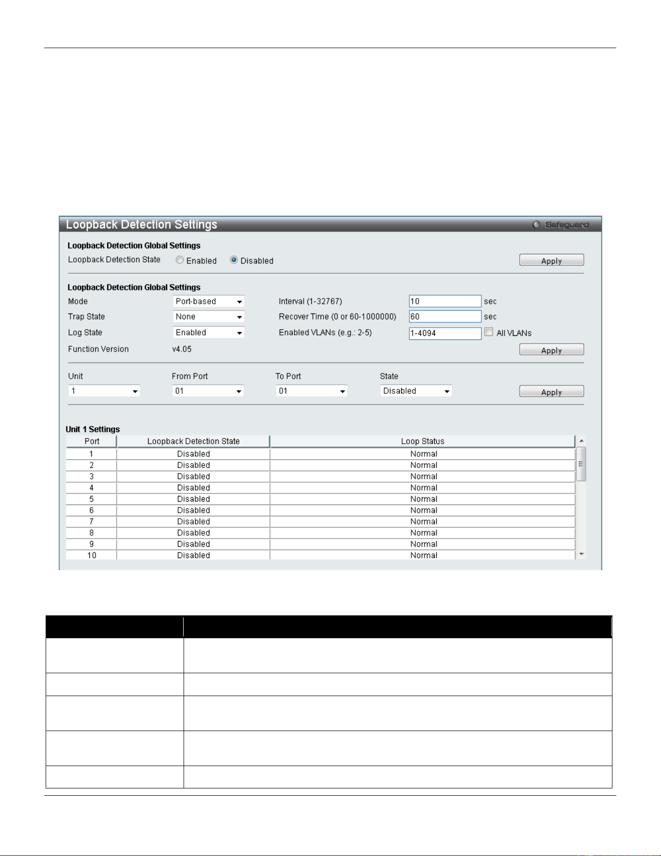
xStack® DGS-3420 Series Layer 2 Managed Stackable Gigabit Switch Web UI Reference Guide
329
Loopback Detection Settings
The Loopback Detection (LBD) function is used to detect the loop created by a specific port. This feature is used to
temporarily shut down a port on the Switch or block traffic through specific VLANs when a CTP (Configuration Testing
Protocol) packet has been looped back to the Switch. When the Switch detects CTP packets received from a port or a
VLAN, this signifies a loop on the network. The Switch will automatically block the port or the VLAN and send an alert
to the administrator. The Loopback Detection port will restart (change to normal state) when the Loopback Detection
Recover Time times out. The Loopback Detection function can be implemented on a range of ports at a time. The user
may enable or disable this function using the drop-down menu.
To view this window, click Security > Loopback Detection Settings as shown below:
Figure 8-57 Loopback Detection Settings window
The fields that can be configured are described below:
Parameter Description
Loopback Detection
State
Use the radio button to enable or disable loopback detection. The default is Disabled.
Mode Use the drop-down menu to toggle between Port-based and VLAN-based.
Trap State Use the drop-down menu to set the desired trap status: None, Loop Detected, Loop
Cleared, or Both.
Log State
Use the drop-down menu to enable or disable the state of the log for loopback
detection.
Interval (1-32767)
The time interval (in seconds) that the device will transmit all the CTP (Configuration
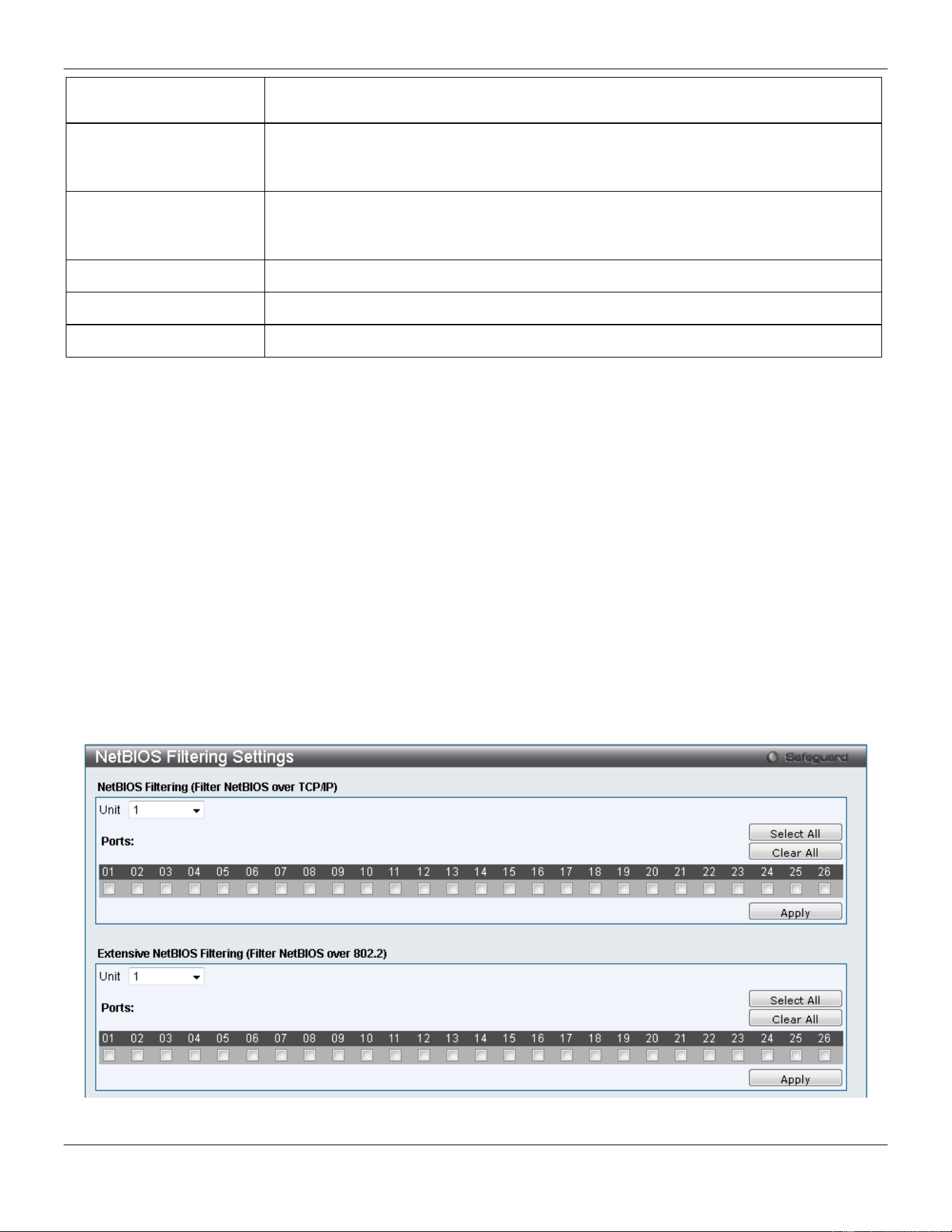
xStack® DGS-3420 Series Layer 2 Managed Stackable Gigabit Switch Web UI Reference Guide
330
Test Protocol) packets to detect a loop-back event. The valid range is from 1 to 32767
seconds. The default setting is 10 seconds.
Recover Time (0 or 60-
1000000)
Time allowed (in seconds) for recovery when a Loopback is detected. The Loop-detect
Recover Time can be set at 0 seconds, or 60 to 1000000 seconds. Entering 0 will
disable the Loop-detect Recover Time. The default is 60 seconds.
Enabled VLANs
This option is used to configure the loopback detection function for the VLANs on
VLAN-based mode. Enter the list of VLAN used for this configuration here. Tick the All
VLANs option to enable this option on all the VLANs configured on this switch.
Unit
Select the unit you wish to configure.
From Port / To Port
Select a range of ports to use for this configuration.
State Use the drop-down menu to toggle between Enabled and Disabled.
Click the Apply button to accept the changes made for each individual section.
NetBIOS Filtering Settings
NetBIOS is an application programming interface, providing a set of functions that applications use to communicate
across networks. NetBEUI, the NetBIOS Enhanced User Interface, was created as a data-link-layer frame structure for
NetBIOS. A simple mechanism to carry NetBIOS traffic, NetBEUI has been the protocol of choice for small MS-DOS-
and Windows-based workgroups. NetBIOS no longer lives strictly inside of the NetBEUI protocol. Microsoft worked to
create the international standards described in RFC 1001 and RFC 1002, NetBIOS over TCP/IP (NBT).
If the network administrator wants to block the network communication on more than two computers which use
NETBUEI protocol, it can use NETBIOS filtering to filter these kinds of packets.
If the user enables the NETBIOS filter, the switch will create one access profile and three access rules automatically. If
the user enables the extensive NETBIOS filter, the switch will create one more access profile and one more access
rule.
To view this window, click Security > NetBIOS Filtering Settings as shown below:
Figure 8-58 NetBIOS Filtering Settings window
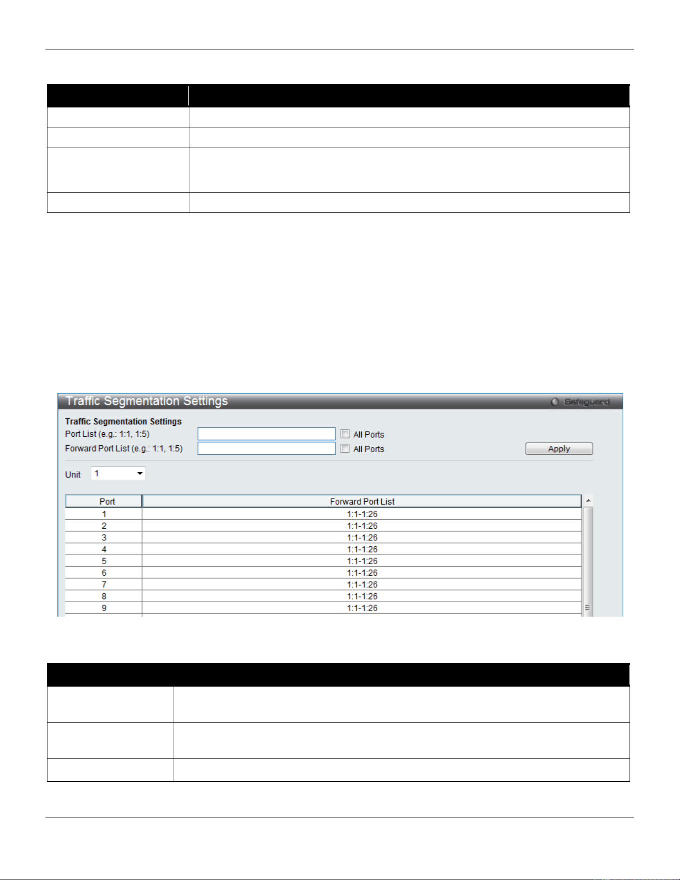
xStack® DGS-3420 Series Layer 2 Managed Stackable Gigabit Switch Web UI Reference Guide
331
The fields that can be configured are described below:
Parameter Description
Unit
Select the unit you want to configure.
NetBIOS Filtering Ports
Select the appropriate port to include in the NetBIOS filtering configuration.
Extensive NetBIOS
Filtering Ports
Select the appropriate port to include in the Extensive NetBIOS filtering configuration.
Extensive NetBIOS is NetBIOS over 802.3. The Switch will deny the NetBIOS over
802.3 frame on these enabled ports.
Ports
Tick the appropriate ports to be configured.
Click the Select All button to select all ports in each individual section.
Click the Clear All button to deselect all ports in each individual section.
Click the Apply button to accept the changes made for each individual section.
Traffic Segmentation Settings
Traffic segmentation is used to limit traffic flow from a single or group of ports, to a group of ports. This method of
segmenting the flow of traffic is similar to using VLANs to limit traffic, but is more restrictive. It provides a method of
directing traffic that does not increase the overhead of the master switch CPU.
To view this window, click Security > Traffic Segmentation Settings as shown below:
Figure 8-59 Traffic Segmentation Settings window
The fields that can be configured are described below:
Parameter Description
Port List Enter a port or list of ports to be included in the traffic segmentation setup. Tick the All
Ports check box to select all ports for the configuration.
Forward Port List Enter a port or list of ports to be included in the traffic segmentation setup. Tick the All
Ports check box to select all the ports for the configuration.
Unit
Select the unit you wish to configure.
Click the Apply button to accept the changes made.
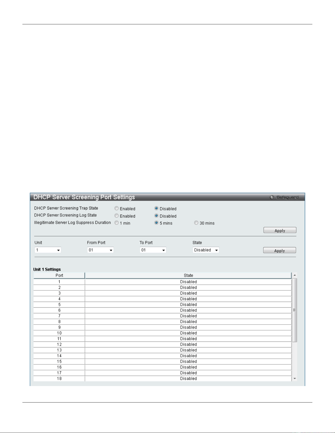
xStack® DGS-3420 Series Layer 2 Managed Stackable Gigabit Switch Web UI Reference Guide
332
DHCP Server Screening
This function allows the user to not only to restrict all DHCP Server packets but also to receive any specified DHCP
server packet by any specified DHCP client, it is useful when one or more DHCP servers are present on the network
and both provide DHCP services to different distinct groups of clients.
The first time the DHCP filter is enabled it will create both an access profile entry and an access rule per port entry, it
will also create other access rules. These rules are used to block all DHCP server packets. In addition to a permit
DHCP entry it will also create one access profile and one access rule entry the first time the DHCP client MAC address
is used as the client MAC address. The Source IP address is the same as the DHCP server’s IP address (UDP port
number 68). These rules are used to permit the DHCP server packets with specific fields, which the user has
configured.
When DHCP Server filter function is enabled all DHCP Server packets will be filtered from a specific port.
DHCP Server Screening Port Settings
The Switch supports DHCP Server Screening, a feature that denies access to rogue DHCP servers. When the DHCP
server filter function is enabled, all DHCP server packets will be filtered from a specific port.
To view this window, click Security > DHCP Server Screening > DHCP Server Screening Port Settings as shown
below:
Figure 8-60 DHCP Server Screening Port Settings window
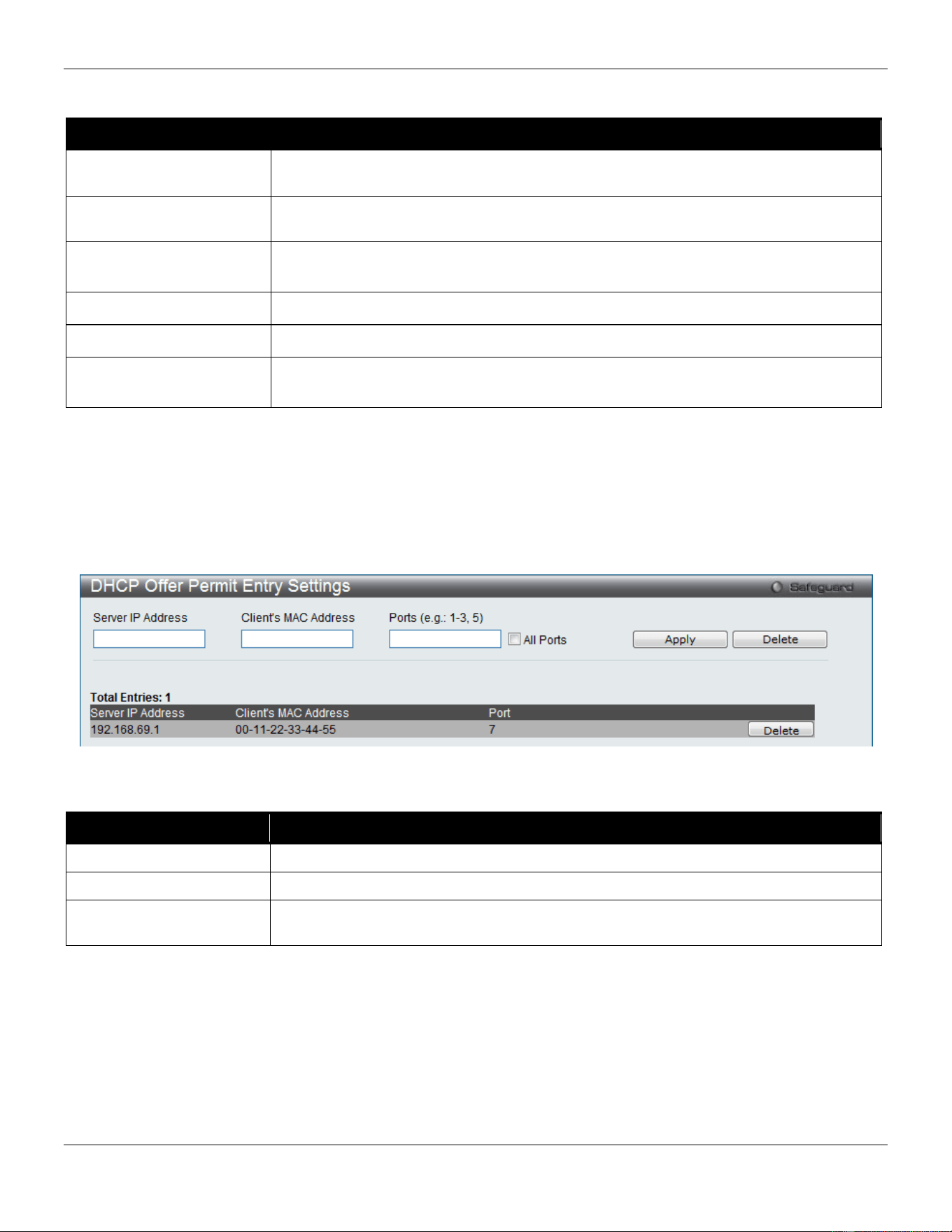
xStack® DGS-3420 Series Layer 2 Managed Stackable Gigabit Switch Web UI Reference Guide
333
The fields that can be configured are described below:
Parameter Description
DHCP Server Screening
Trap State
Click to enable or disable filtering DHCP server trap.
DHCP Server Screening
Log State
Click to enable or disable filtering DHCP server log.
Illegal Server Log
Suppress Duration
Choose an illegal server log suppress duration of 1 minute, 5 minutes, or 30 minutes.
Unit
Select the unit you wish to configure.
From Port / To Port
A consecutive group of ports may be configured starting with the selected port.
State Choose Enabled to enable the DHCP server screening or Disabled to disable it. The
default is Disabled.
Click the Apply button to accept the changes made for each individual section.
DHCP Offer Permit Entry Settings
Users can add or delete permit entries on this page.
To view this window, click Security > DHCP Server Screening > DHCP Offer Permit Entry Settings as shown below:
Figure 8-61 DHCP Offer Permit Entry Settings window
The fields that can be configured are described below:
Parameter Description
Server IP Address
The IP address of the DHCP server to be permitted.
Client’s MAC Address
The MAC address of the DHCP client.
Ports The port numbers of the filter DHCP server. Tick the All Ports check box to include all
the ports on this switch for this configuration.
Click the Apply button to accept the changes made.
Click the Delete button to remove the specific entry based on the information entered.
Filter DHCPv6 Server
This page has two purposes: to specify to filter all DHCP server packets on the specific port and to specify to allow
some DHCP server packets with pre-defined server IP addresses and client MAC addresses. With this function, we
can restrict the DHCP server to service specific DHCP clients. This is useful when two DHCP servers are present on
the network; one of them can provide the private IP address and the other can provide the public IP address.
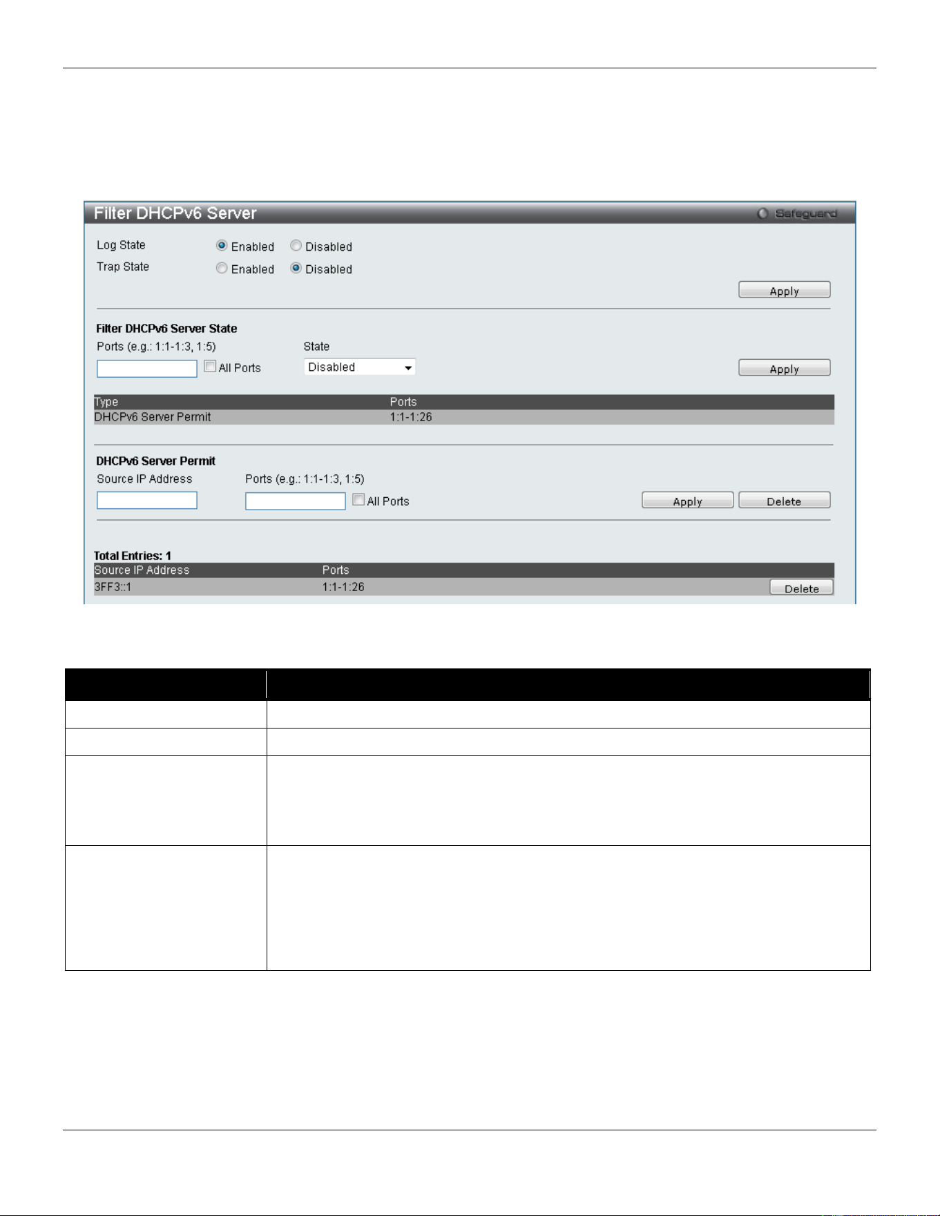
xStack® DGS-3420 Series Layer 2 Managed Stackable Gigabit Switch Web UI Reference Guide
334
Enabling filter DHCP server port state will create one access profile and create one access rule per port (UDP port is
equal to 67). Filter commands in this file will share the same access profile. Addition of a permit DHCP entry will create
one access profile and create one access rule. Filter commands in this file will share the same access profile.
To view this window, click Security > DHCP Server Screening > Filter DHCPv6 Server as shown below:
Figure 8-62 Filter DHCPv6 Server window
The fields that can be configured are described below:
Parameter Description
Log State
This option is used to enable or disable the log for a DHCP server filter event.
Trap State
This option is used to enable or disable the trap for a DHCP server filter event.
Filter DHCPv6 Server
State
This option is used to configure the filter DHCPv6 server state.
Ports: Enter the list of ports used for this configuration here. Tick this All Ports option
to include all the port in this configuration.
State: Select to enable or disable this option’s state.
DHCPv6 Server Permit
This option used to create a DHCPv6 server permit entry. The specific DHCPv6
server packets with the source IPv6 address will be forward on the specified port(s).
Source IP Address: Enter the source address of the entry which will be created into
the Filter DHCPv6 server forward list.
Ports: Enter the list of ports, used for this configuration, here. Tick this All Ports
option to include all the port in this configuration.
Click the Apply button to accept the changes made.
Click the Delete button to remove the specific entry based on the information entered.
Filter ICMPv6
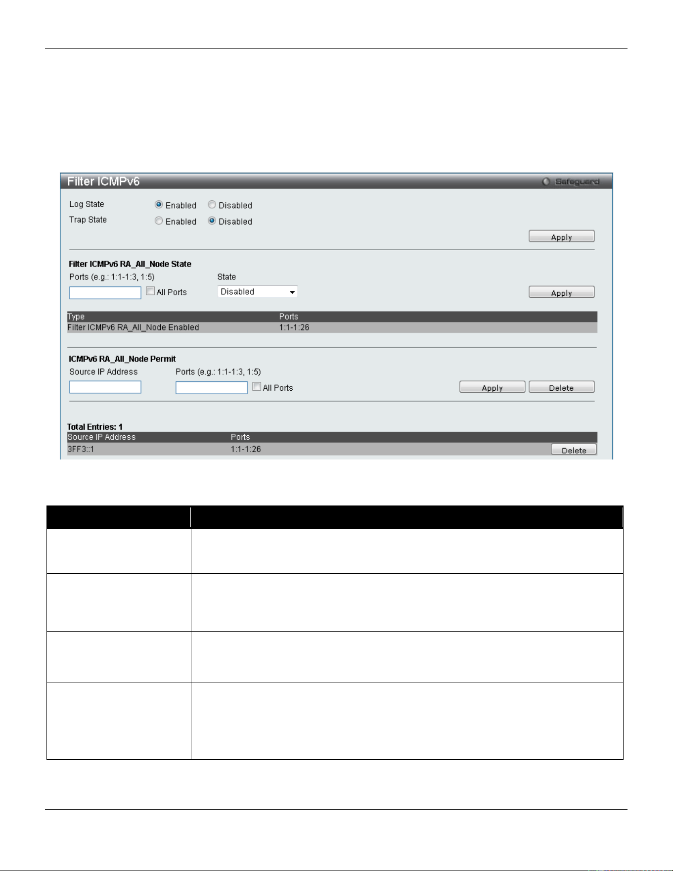
xStack® DGS-3420 Series Layer 2 Managed Stackable Gigabit Switch Web UI Reference Guide
335
This window is used to configure the state of the filter ICMPv6 RA all-nodes packets on the switch. The filter ICMPv6
RA all-nodes function is used to filter the ICMPv6 RA all-nodes packets on the specific port(s) and receive the trust
packets from the specific source. This feature can be protected network usable when a malicious host sends ICMPv6
RA all-nodes packets.
Note: It only needs to filter the packet of which the destination address is the all-nodes multicast address (FF02::1).
To view this window, click Security > DHCP Server Screening > Filter ICMPv6 as shown below:
Figure 8-63 Filter ICMPv6 window
The fields that can be configured are described below:
Parameter Description
Log State
This option is used to enable or disable the filter ICMPv6 RA All-nodes log state.
When the filter ICMPv6 RA all-nodes log state is enabled, the log of the “Detected
untrusted ICMPv6 All-nodes RA” will be generated.
Trap State
This option is used to enable or disable the filter ICMPv6 RA all-nodes trap state.
When the filter ICMPv6 RA all-nodes trap state is enabled, the trap of the “illegal
ICMPv6 all-nodes RA is detected” will be sent out. If the ICMPv6 RA all-nodes server
trap state is disabled, no trap will be sent out.
Filter ICMPv6
RA_All_Node State
This option is used to configure the filter ICMPv6 state.
Ports: Tick this All Ports option to include all the port in this configuration.
State: Select to enable or disable this option’s state.
ICMPv6 RA_All_Node
Permit
This option is used to create a filter ICMPv6 RA All-nodes permit entry.
Source IP Address: Enter the source address of entry which will be created into the
Filter ICMPv6 RA All-nodes forward list here.
Ports: Enter the list of ports, used for this configuration, here. Tick this All Ports
option to include all the port in this configuration.
Click the Apply button to accept the changes made.
Click the Delete button to remove the specific entry based on the information entered.

xStack® DGS-3420 Series Layer 2 Managed Stackable Gigabit Switch Web UI Reference Guide
336
Access Authentication Control
The TACACS / XTACACS / TACACS+ / RADIUS commands allow users to secure access to the Switch using the
TACACS / XTACACS / TACACS+ / RADIUS protocols. When a user logs in to the Switch or tries to access the
administrator level privilege, he or she is prompted for a password. If TACACS / XTACACS / TACACS+ / RADIUS
authentication is enabled on the Switch, it will contact a TACACS / XTACACS / TACACS+ / RADIUS server to verify
the user. If the user is verified, he or she is granted access to the Switch.
There are currently three versions of the TACACS security protocol, each a separate entity. The Switch's software
supports the following versions of TACACS:
• TACACS (Terminal Access Controller Access Control System) - Provides password checking and
authentication, and notification of user actions for security purposes utilizing via one or more centralized
TACACS servers, utilizing the UDP protocol for packet transmission.
• Extended TACACS (XTACACS) - An extension of the TACACS protocol with the ability to provide more types
of authentication requests and more types of response codes than TACACS. This protocol also uses UDP to
transmit packets.
• TACACS+ (Terminal Access Controller Access Control System plus) - Provides detailed access control
for authentication for network devices. TACACS+ is facilitated through Authentication commands via one or
more centralized servers. The TACACS+ protocol encrypts all traffic between the Switch and the TACACS+
daemon, using the TCP protocol to ensure reliable delivery
In order for the TACACS / XTACACS / TACACS+ / RADIUS security function to work properly, a TACACS / XTACACS
/ TACACS+ / RADIUS server must be configured on a device other than the Switch, called an Authentication Server
Host and it must include usernames and passwords for authentication. When the user is prompted by the Switch to
enter usernames and passwords for authentication, the Switch contacts the TACACS / XTACACS / TACACS+ /
RADIUS server to verify, and the server will respond with one of three messages:
The server verifies the username and password, and the user is granted normal user privileges on the Switch.
The server will not accept the username and password and the user is denied access to the Switch.
The server doesn't respond to the verification query. At this point, the Switch receives the timeout from the server and
then moves to the next method of verification configured in the method list.
The Switch has four built-in Authentication Server Groups, one for each of the TACACS, XTACACS, TACACS+ and
RADIUS protocols. These built-in Authentication Server Groups are used to authenticate users trying to access the
Switch. The users will set Authentication Server Hosts in a preferable order in the built-in Authentication Server Groups
and when a user tries to gain access to the Switch, the Switch will ask the first Authentication Server Hosts for
authentication. If no authentication is made, the second server host in the list will be queried, and so on. The built-in
Authentication Server Groups can only have hosts that are running the specified protocol. For example, the TACACS
Authentication Server Groups can only have TACACS Authentication Server Hosts.
The administrator for the Switch may set up six different authentication techniques per user-defined method list
(TACACS / XTACACS / TACACS+ / RADIUS / local / none) for authentication. These techniques will be listed in an
order preferable, and defined by the user for normal user authentication on the Switch, and may contain up to eight
authentication techniques. When a user attempts to access the Switch, the Switch will select the first technique listed
for authentication. If the first technique goes through its Authentication Server Hosts and no authentication is returned,
the Switch will then go to the next technique listed in the server group for authentication, until the authentication has
been verified or denied, or the list is exhausted.
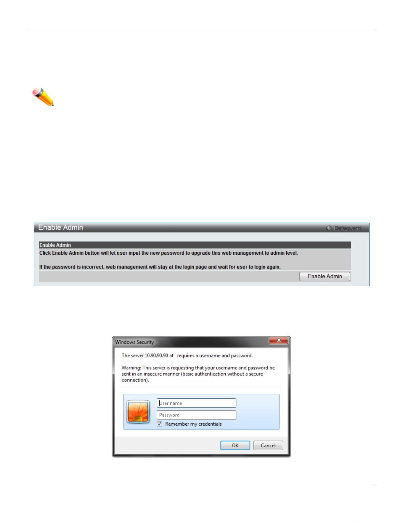
xStack® DGS-3420 Series Layer 2 Managed Stackable Gigabit Switch Web UI Reference Guide
337
Users granted access to the Switch will be granted normal user privileges on the Switch. To gain access to
administrator level privileges, the user must access the Enable Admin window and then enter a password, which was
previously configured by the administrator of the Switch.
This Switch supports the assignment of user privileges from the TACACS+ server.
NOTE: TACACS, XTACACS and TACACS+ are separate entities and are not compatible. The Switch and
the server must be configured exactly the same, using the same protocol. (For example, if the
Switch is set up for TACACS authentication, so must be the host server.)
Enable Admin
Users who have logged on to the Switch on the normal user level and wish to be promoted to the administrator level
can use this window. After logging on to the Switch, users will have only user level privileges. To gain access to
administrator level privileges, the user will open this window and will have to enter an authentication password.
Possible authentication methods for this function include TACACS/XTACACS/TACACS+/RADIUS, user defined server
groups, local enable (local account on the Switch), or no authentication (none). Because XTACACS and TACACS do
not support the enable function, the user must create a special account on the server host, which has the username
"enable", and a password configured by the administrator that will support the "enable" function. This function becomes
inoperable when the authentication policy is disabled.
To view this window, click Security > Access Authentication Control > Enable Admin as shown below:
Figure 8-64 Enable Admin window
When this window appears, click the Enable Admin button revealing a window for the user to enter authentication
(password, username), as shown below. A successful entry will promote the user to Administrator level privileges on
the Switch.
Figure 8-65 Log-in Page
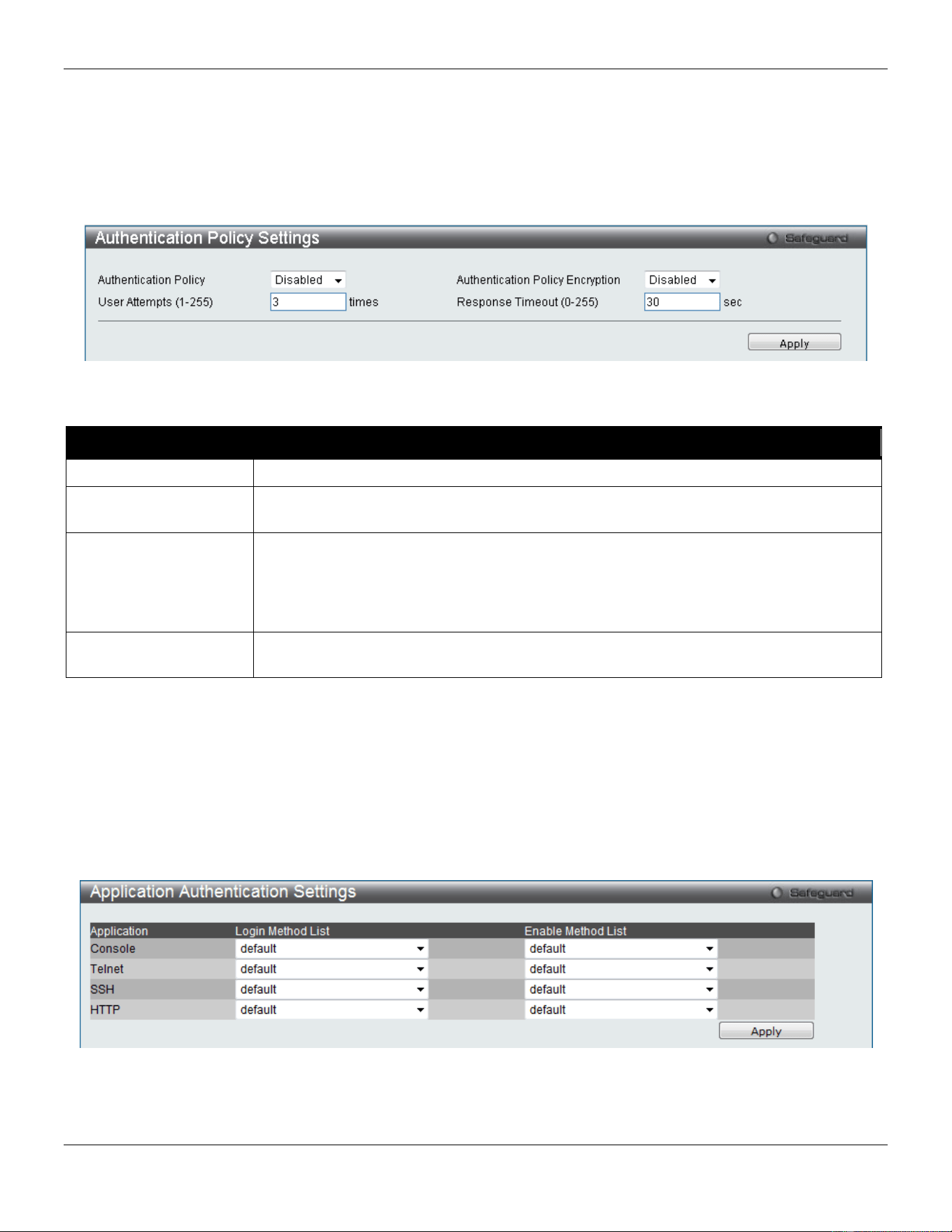
xStack® DGS-3420 Series Layer 2 Managed Stackable Gigabit Switch Web UI Reference Guide
338
Authentication Policy Settings
Users can enable an administrator-defined authentication policy for users trying to access the Switch. When enabled,
the device will check the Login Method List and choose a technique for user authentication upon login.
To view this window, click Security > Access Authentication Control > Authentication Policy Settings as shown
below:
Figure 8-66 Authentication Policy Settings window
The fields that can be configured are described below:
Parameter Description
Authentication Policy
Use the drop-down menu to enable or disable the Authentication Policy on the Switch.
Authentication Policy
Encryption
Use the drop-down menu to enable or disable authentication policy encryption.
User Attempts (1-255)
Enter the maximum number of times that the Switch will accept authentication attempts.
Users failing to be authenticated after the set amount of attempts will be denied access
to the Switch and will be locked out of further authentication attempts. Command line
interface users will have to wait 60 seconds before another authentication attempt.
Telnet and web users will be disconnected from the Switch. The default setting is 3.
Response Timeout
(0-255)
Enter the time that the Switch will wait for a response of authentication from the user.
The default setting is 30 seconds.
Click the Apply button to accept the changes made.
Application Authentication Settings
Users can configure Switch configuration applications (console, Telnet, SSH, web) for login at the user level and at the
administration level (Enable Admin) utilizing a previously configured method list.
To view this window, click Security > Access Authentication Control > Application Authentication Settings as
shown below:
Figure 8-67 Application Authentication Settings window
The fields that can be configured or displayed are described below:
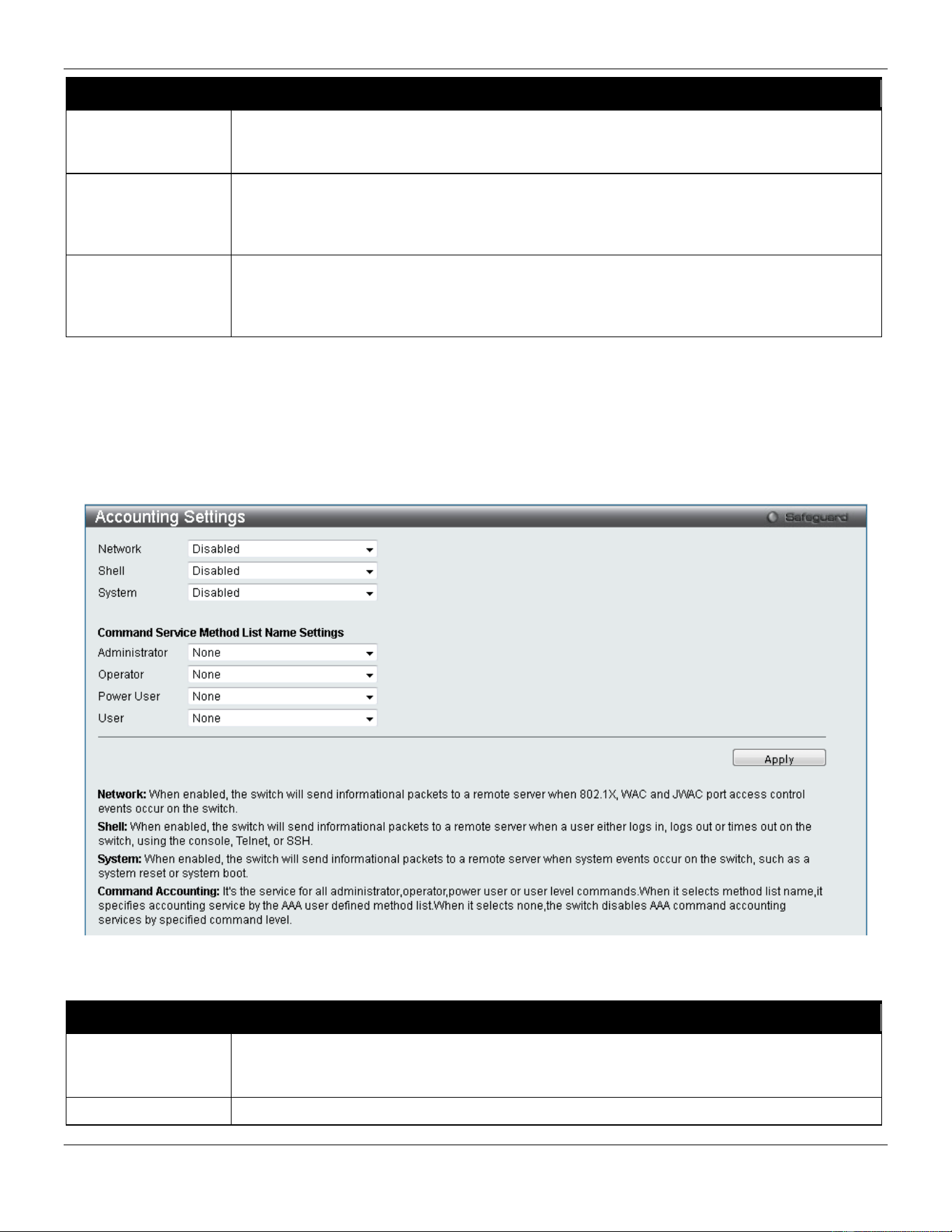
xStack® DGS-3420 Series Layer 2 Managed Stackable Gigabit Switch Web UI Reference Guide
339
Parameter Description
Application
Lists the configuration applications on the Switch. The user may configure the Login Method
List and Enable Method List for authentication for users utilizing the Console (Command
Line Interface) application, the Telnet application, SSH, and the Web (HTTP) application.
Login Method List
Use the drop-down menu to configure an application for normal login on the user level,
utilizing a previously configured method list. The user may use the default Method List or
other Method List configured by the user. See the Login Method Lists Settings
window, in
this section, for more information.
Enable Method List
Use the drop-down menu to configure an application to promote user level to admin-level
users utilizing a previously configured method list. The user may use the default Method
List or other Method List configured by the user. See the Login Method Lists Settings
window, in this section, for more information
Click the Apply button to accept the changes made.
Accounting Settings
Users can configure the state of the specified RADIUS accounting service.
To view this window, click Security > Access Authentication Control > Accounting Settings as shown below:
Figure 8-68 Accounting Settings window
The fields that can be configured are described below:
Parameter Description
Network When RADIUS Only is selected, the Switch will send network informational packets to a
remote RADIUS server. When Method List Name is selected, the Switch will send network
informational packets based on the method list created.
Shell
When RADIUS Only is selected, the Switch will send shell informational packets to a
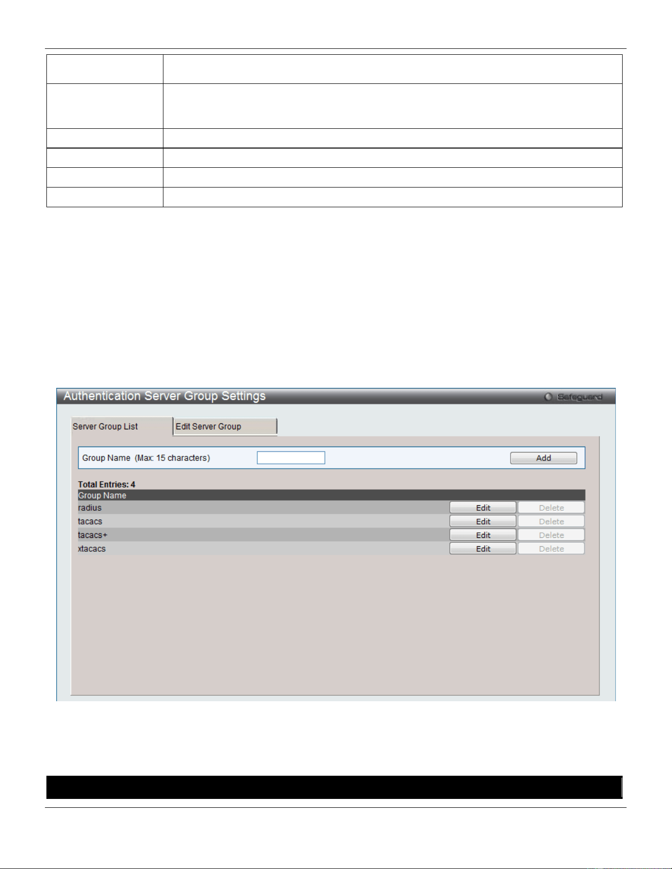
xStack® DGS-3420 Series Layer 2 Managed Stackable Gigabit Switch Web UI Reference Guide
340
remote RADIUS server. When Method List Name is selected, the Switch will send shell
informational packets based on the method list created.
System When RADIUS Only is selected, the Switch will send system informational packets to a
remote RADIUS server. When Method List Name is selected, the Switch will send system
informational packets based on the method list created.
Administrator
When selected, the accounting service for all administrator level commands will be enabled.
Operator
When selected, the accounting service for all operator level commands will be enabled.
Power User
When selected, the accounting service for all power-user level commands will be enabled.
User
When selected, the accounting service for all user level commands will be enabled.
Click the Apply button to accept the changes made.
Authentication Server Group Settings
This window is used to set up Authentication Server Groups on the Switch. A server group is a technique used to
group TACACS/XTACACS/TACACS+/RADIUS server hosts into user-defined categories for authentication using
method lists. The user may define the type of server group by protocol or by previously defined server group. The
Switch has four built-in Authentication Server Groups that cannot be removed but can be modified. Up to eight
authentication server hosts may be added to any particular group.
To view this window, click Security > Access Authentication Control > Authentication Server Group Settings as
shown below:
Figure 8-69 Authentication Server Group Settings – Server Group List window
This window displays the Authentication Server Groups on the Switch. The Switch has four built-in Authentication
Server Groups that cannot be removed but can be modified.
The fields that can be configured are described below:
Parameter Description
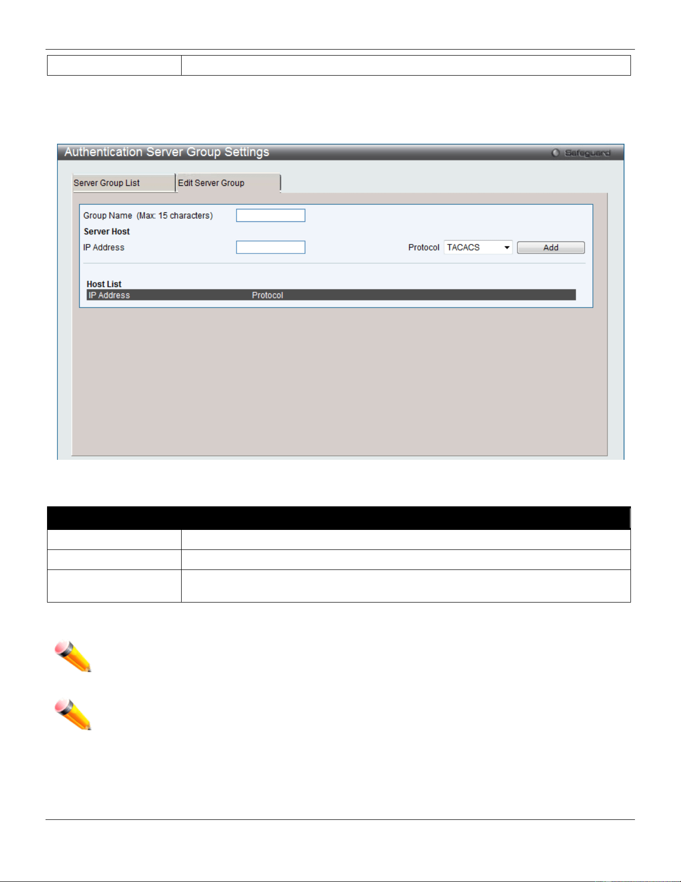
xStack® DGS-3420 Series Layer 2 Managed Stackable Gigabit Switch Web UI Reference Guide
341
Group Name
Enter a new server group name.
Click the Add button to add a new entry based on the information entered.
Click the Edit button (or the Edit Server Group tab) to re-configure the specific entry.
Click the Edit Server Group tab to see the following window.
Figure 8-70 Authentication Server Group Settings – Edit Server Group window
The fields that can be configured are described below:
Parameter Description
Group Name
Enter a server group name.
IP Address
Enter the IP address of the server host.
Protocol use the drop-down menu to choose the Protocol associated with the IP address of the
Authentication Server Host
Click the Add button to add a new entry based on the information entered.
NOTE: The user must configure Authentication Server Hosts using the Authentication Server Hosts
window before adding hosts to the list. Authentication Server Hosts must be configured for their
specific protocol on a remote centralized server before this function can work properly.
NOTE: The three built-in server groups can only have server hosts running the same TACACS daemon.
TACACS/XTACACS/TACACS+ protocols are separate entities and are not compatible with each
other.
Authentication Server Settings
User-defined Authentication Server Hosts for the TACACS / XTACACS / TACACS+ / RADIUS security protocols can
be set on the Switch. When a user attempts to access the Switch with Authentication Policy enabled, the Switch will
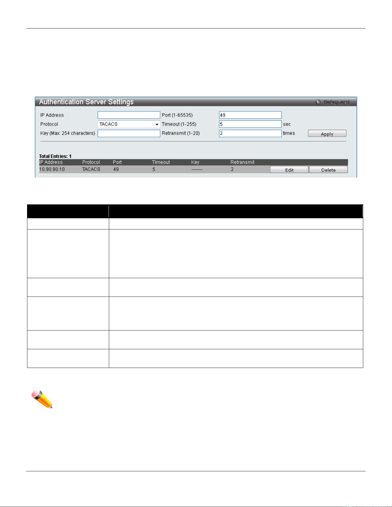
xStack® DGS-3420 Series Layer 2 Managed Stackable Gigabit Switch Web UI Reference Guide
342
send authentication packets to a remote TACACS / XTACACS / TACACS+ / RADIUS server host on a remote host.
The TACACS / XTACACS / TACACS+ / RADIUS server host will then verify or deny the request and return the
appropriate message to the Switch. More than one authentication protocol can be run on the same physical server host
but, remember that TACACS / XTACACS / TACACS+ / RADIUS are separate entities and are not compatible with
each other. The maximum supported number of server hosts is 16.
To view this window, click Security > Access Authentication Control > Authentication Server Settings as shown
below:
Figure 8-71 Authentication Server Settings window
The fields that can be configured are described below:
Parameter Description
IP Address
The IP address of the remote server host to add.
Protocol
The protocol used by the server host. The user may choose one of the following:
TACACS - Enter this parameter if the server host utilizes the TACACS protocol.
XTACACS - Enter this parameter if the server host utilizes the XTACACS protocol.
TACACS+ - Enter this parameter if the server host utilizes the TACACS+ protocol.
RADIUS - Enter this parameter if the server host utilizes the RADIUS protocol.
Key
Authentication key to be shared with a configured TACACS+ or RADIUS servers only.
Specify an alphanumeric string up to 254 characters.
Port (1-65535) Enter a number between 1 and 65535 to define the virtual port number of the
authentication protocol on a server host. The default port number is 49 for
TACACS/XTACACS/TACACS+ servers and 1812 for RADIUS servers but the user
may set a unique port number for higher security.
Timeout (1-255)
Enter the time in seconds the Switch will wait for the server host to reply to an
authentication request. The default value is 5 seconds.
Retransmit (1-20)
Enter the value in the retransmit field to change how many times the device will resend
an authentication request when the TACACS server does not respond.
Click the Apply button to accept the changes made.
NOTE: More than one authentication protocol can be run on the same physical server host but, remember
that TACACS/XTACACS/TACACS+ are separate entities and are not compatible with each other.
Login Method Lists Settings
User-defined or default Login Method List of authentication techniques can be configured for users logging on to the
Switch. The sequence of techniques implemented in this command will affect the authentication result. For example, if
a user enters a sequence of techniques, for example TACACS - XTACACS- local, the Switch will send an
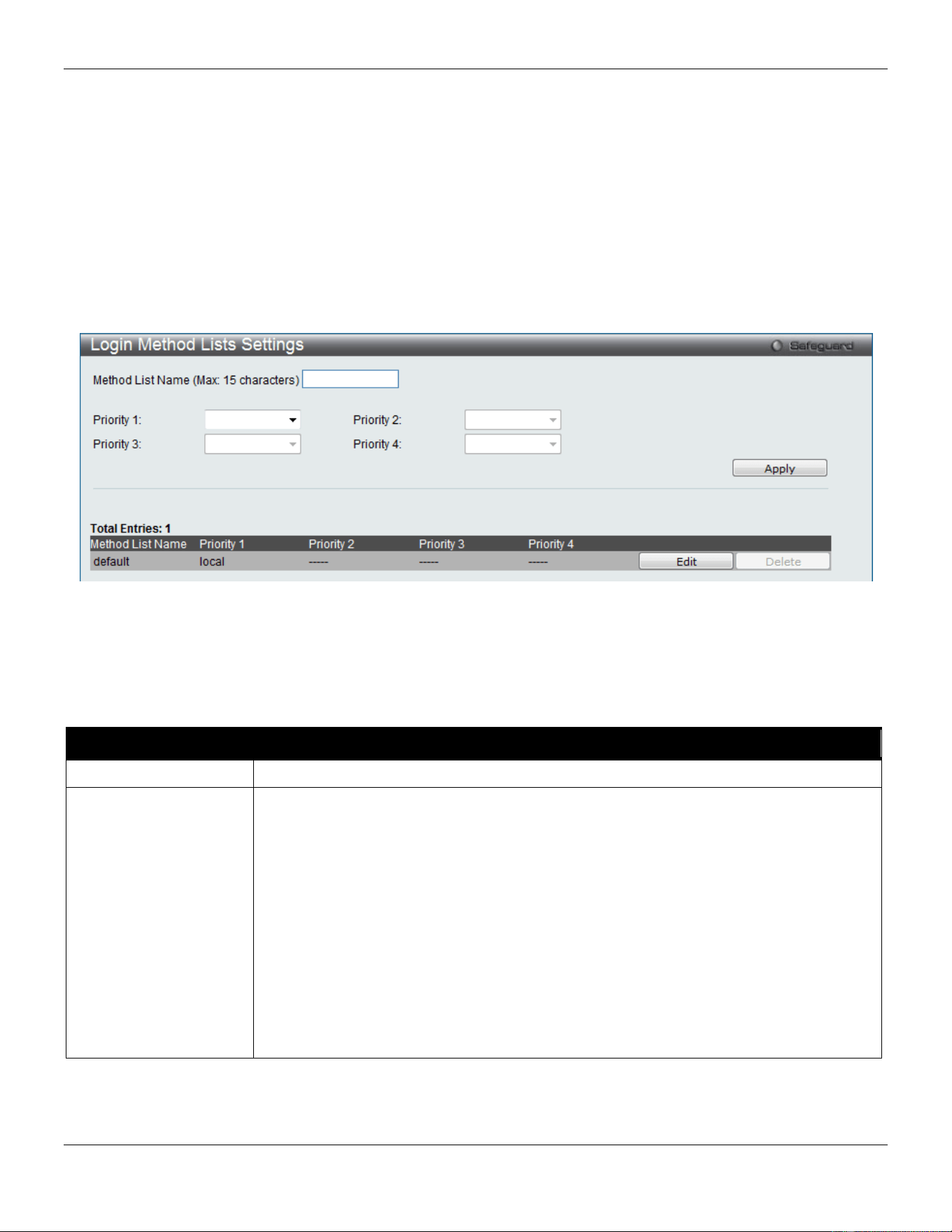
xStack® DGS-3420 Series Layer 2 Managed Stackable Gigabit Switch Web UI Reference Guide
343
authentication request to the first TACACS host in the server group. If no response comes from the server host, the
Switch will send an authentication request to the second TACACS host in the server group and so on, until the list is
exhausted. At that point, the Switch will restart the same sequence with the following protocol listed, XTACACS. If no
authentication takes place using the XTACACS list, the local account database set in the Switch is used to
authenticate the user. When the local method is used, the privilege level will be dependent on the local account
privilege configured on the Switch.
Successful login using any of these techniques will give the user a "User" privilege only. If the user wishes to upgrade
his or her status to the administrator level, the user must use the Enable Admin window, in which the user must enter
a previously configured password, set by the administrator.
To view this window, click Security > Access Authentication Control > Login Method Lists Settings as shown
below:
Figure 8-72 Login Method Lists Settings window
The Switch contains one Method List that is set and cannot be removed, yet can be modified. To delete a Login
Method List defined by the user, click the Delete button corresponding to the entry desired to be deleted. To modify a
Login Method List, click its corresponding Edit button.
The fields that can be configured are described below:
Parameter Description
Method List Name
Enter a method list name defined by the user of up to 15 characters.
Priority 1, 2, 3, 4
The user may add one, or a combination of up to four of the following authentication
methods to this method list:
tacacs - Adding this parameter will require the user to be authenticated using the
TACACS protocol from a remote TACACS server.
xtacacs - Adding this parameter will require the user to be authenticated using the
XTACACS protocol from a remote XTACACS server.
tacacs+ - Adding this parameter will require the user to be authenticated using the
TACACS+ protocol from a remote TACACS+ server.
radius - Adding this parameter will require the user to be authenticated using the
RADIUS protocol from a remote RADIUS server.
local - Adding this parameter will require the user to be authenticated using the local
user account database on the Switch.
none - Adding this parameter will require no authentication needed to access the Switch.
Click the Apply button to accept the changes made.
Click the Edit button to re-configure the specific entry.
Click the Delete button to remove the specific entry.
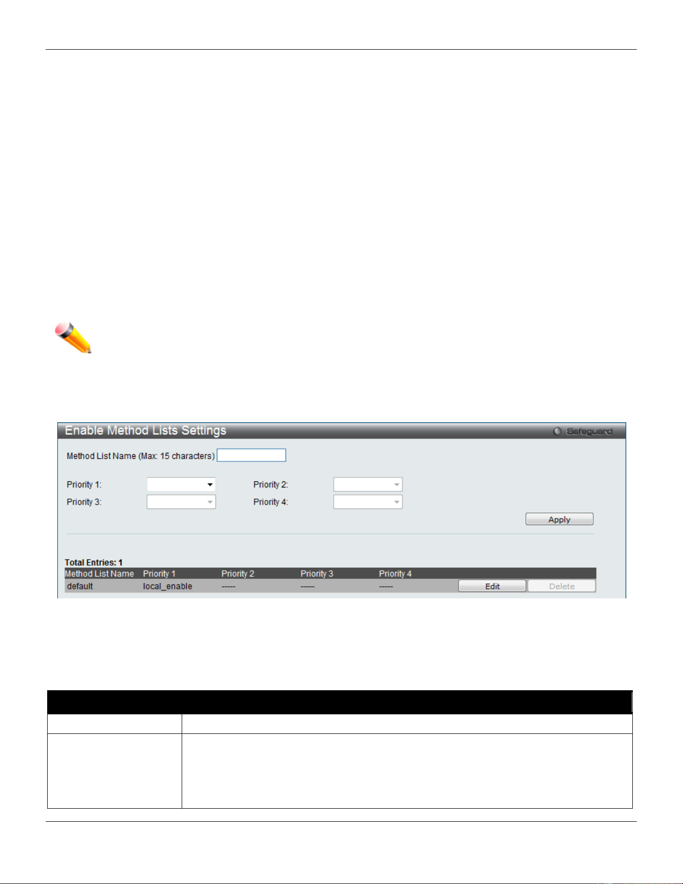
xStack® DGS-3420 Series Layer 2 Managed Stackable Gigabit Switch Web UI Reference Guide
344
Enable Method Lists Settings
Users can set up Method Lists to promote users with user level privileges to Administrator (Admin) level privileges
using authentication methods on the Switch. Once a user acquires normal user level privileges on the Switch, he or
she must be authenticated by a method on the Switch to gain administrator privileges on the Switch, which is defined
by the Administrator. A maximum of eight Enable Method Lists can be implemented on the Switch, one of which is a
default Enable Method List. This default Enable Method List cannot be deleted but can be configured.
The sequence of methods implemented in this command will affect the authentication result. For example, if a user
enters a sequence of methods like TACACS - XTACACS - Local Enable, the Switch will send an authentication request
to the first TACACS host in the server group. If no verification is found, the Switch will send an authentication request
to the second TACACS host in the server group and so on, until the list is exhausted. At that point, the Switch will
restart the same sequence with the following protocol listed, XTACACS. If no authentication takes place using the
XTACACS list, the Local Enable password set in the Switch is used to authenticate the user.
Successful authentication using any of these methods will give the user an "Admin" privilege.
NOTE: To set the Local Enable Password, see the next section, entitled Local Enable Password.
To view this window, click Security > Access Authentication Control > Enable method Lists Settings as shown
below:
Figure 8-73 Enable method Lists Settings window
To delete an Enable Method List defined by the user, click the Delete button corresponding to the entry desired to be
deleted. To modify an Enable Method List, click its corresponding Edit button.
The fields that can be configured are described below:
Parameter Description
Method List Name
Enter a method list name defined by the user of up to 15 characters.
Priority 1, 2, 3, 4
The user may add one, or a combination of up to four of the following authentication
methods to this method list:
local_enable - Adding this parameter will require the user to be authenticated using the
local enable password database on the Switch. The local enable password must be set
by the user in the next section entitled Local Enable Password.
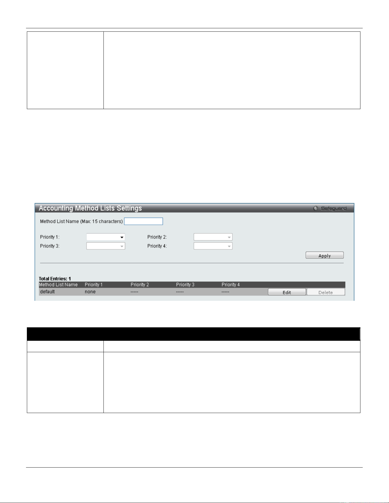
xStack® DGS-3420 Series Layer 2 Managed Stackable Gigabit Switch Web UI Reference Guide
345
none - Adding this parameter will require no authentication needed to access the Switch.
radius - Adding this parameter will require the user to be authenticated using the
RADIUS protocol from a remote RADIUS server.
tacacs - Adding this parameter will require the user to be authenticated using the
TACACS protocol from a remote TACACS server.
xtacacs - Adding this parameter will require the user to be authenticated using the
XTACACS protocol from a remote XTACACS server.
tacacs+ - Adding this parameter will require the user to be authenticated using the
TACACS protocol from a remote TACACS server.
Click the Apply button to accept the changes made.
Click the Edit button to re-configure the specific entry.
Click the Delete button to remove the specific entry.
Accounting Method Lists Settings
Here users can create and configure accounting method lists on the Switch.
To view this window, click Security > Access Authentication Control > Accounting Method Lists Settings as
shown below:
Figure 8-74 Accounting Method Lists Settings window
The fields that can be configured are described below:
Parameter Description
Method List Name
Enter a method list name defined by the user of up to 15 characters.
Priority 1, 2, 3, 4
The user may add one, or a combination of up to four of the following accounting
methods to this method list:
none - Adding this parameter will require no accounting.
radius - Adding this parameter will require the user to be accounting using the RADIUS
protocol from a remote RADIUS server.
tacacs+ - Adding this parameter will require the user to be accounting using the
TACACS protocol from a remote TACACS server.
Click the Apply button to accept the changes made.
Click the Edit button to re-configure the specific entry.
Click the Delete button to an Enable Method List defined by the user.
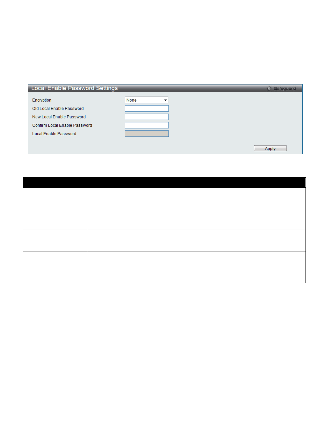
xStack® DGS-3420 Series Layer 2 Managed Stackable Gigabit Switch Web UI Reference Guide
346
Local Enable Password Settings
Users can configure the locally enabled password for Enable Admin. When a user chooses the "local_enable" method
to promote user level privileges to administrator privileges, he or she will be prompted to enter the password configured
here that is locally set on the Switch.
To view this window, click Security > Access Authentication Control > Local Enable Password Settings as shown
below:
Figure 8-75 Local Enable Password Settings window
The fields that can be configured are described below:
Parameter Description
Encryption
Specifies the encryption type to be used for the password.
Plain Text - Specifies that the password entered should be in plain text form.
SHA1 - Specifies that the password entered should be in SHA-1 encrypted form.
Old Local Enable
Password
If a password was previously configured for this entry, enter it here in order to change it
to a new password
New Local Enable
Password
Enter the new password that you wish to set on the Switch to authenticate users
attempting to access Administrator Level privileges on the Switch. The user may set a
password of up to 15 characters.
Confirm Local Enable
Password
Confirm the new password entered above. Entering a different password here from the
one set in the New Local Enabled field will result in a fail message.
Local Enable
Password
After selecting one of the Encryption options, the user can enter the local password
used here.
Click the Apply button to accept the changes made.
Authentication Source IP Interface Settings
This window is used to specify source interface for all outgoing RADIUS and TACACS packets.
To view this window, click Security > Access Authentication Control > Authentication Source IP Interface
Settings as shown below:
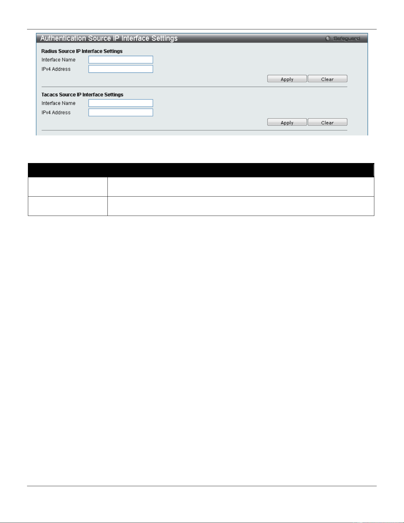
xStack® DGS-3420 Series Layer 2 Managed Stackable Gigabit Switch Web UI Reference Guide
347
Figure 8-76 Authentication Source IP Interface window
The fields that can be configured are described below:
Parameter Description
Interface Name
Enter the interface name that will be used as the source interface for all outgoing
RADIUS and TACACS packets.
IPv4 Address
Enter the IPv4 address that will be used as the source IPv4 address for all outgoing
RADIUS and TACACS packets.
Click the Apply button to accept the changes made.
Click the Clear button to clear out all information entered.
SSL Settings
Secure Sockets Layer, or SSL, is a security feature that will provide a secure communication path between a host and
client through the use of authentication, digital signatures and encryption. These security functions are implemented
through the use of a cipher suite, which is a security string that determines the exact cryptographic parameters,
specific encryption algorithms and key sizes to be used for an authentication session and consists of three levels:
1 Key Exchange: The first part of the Cipher suite string specifies the public key algorithm to be used. This
switch utilizes the Rivest Shamir Adleman (RSA) public key algorithm and the Digital Signature Algorithm
(DSA), specified here as the DHE DSS Diffie-Hellman (DHE) public key algorithm. This is the first
authentication process between client and host as they “exchange keys” in looking for a match and therefore
authentication to be accepted to negotiate encryptions on the following level.
2 Encryption: The second part of the cipher suite that includes the encryption used for encrypting the messages
sent between client and host. The Switch supports two types of cryptology algorithms:
Stream Ciphers – There are two types of stream ciphers on the Switch, RC4 with 40-bit keys and RC4 with
128-bit keys. These keys are used to encrypt messages and need to be consistent between client and host for
optimal use.
CBC Block Ciphers – CBC refers to Cipher Block Chaining, which means that a portion of the previously
encrypted block of encrypted text is used in the encryption of the current block. The Switch supports the 3DES
EDE encryption code defined by the Data Encryption Standard (DES) to create the encrypted text.
3 Hash Algorithm: This part of the cipher suite allows the user to choose a message digest function which will
determine a Message Authentication Code. This Message Authentication Code will be encrypted with a sent
message to provide integrity and prevent against replay attacks. The Switch supports two hash algorithms,
MD5 (Message Digest 5) and SHA (Secure Hash Algorithm).
These three parameters are uniquely assembled in four choices on the Switch to create a three-layered encryption
code for secure communication between the server and the host. The user may implement any one or combination of
the cipher suites available, yet different cipher suites will affect the security level and the performance of the secured
connection. The information included in the cipher suites is not included with the Switch and requires downloading from
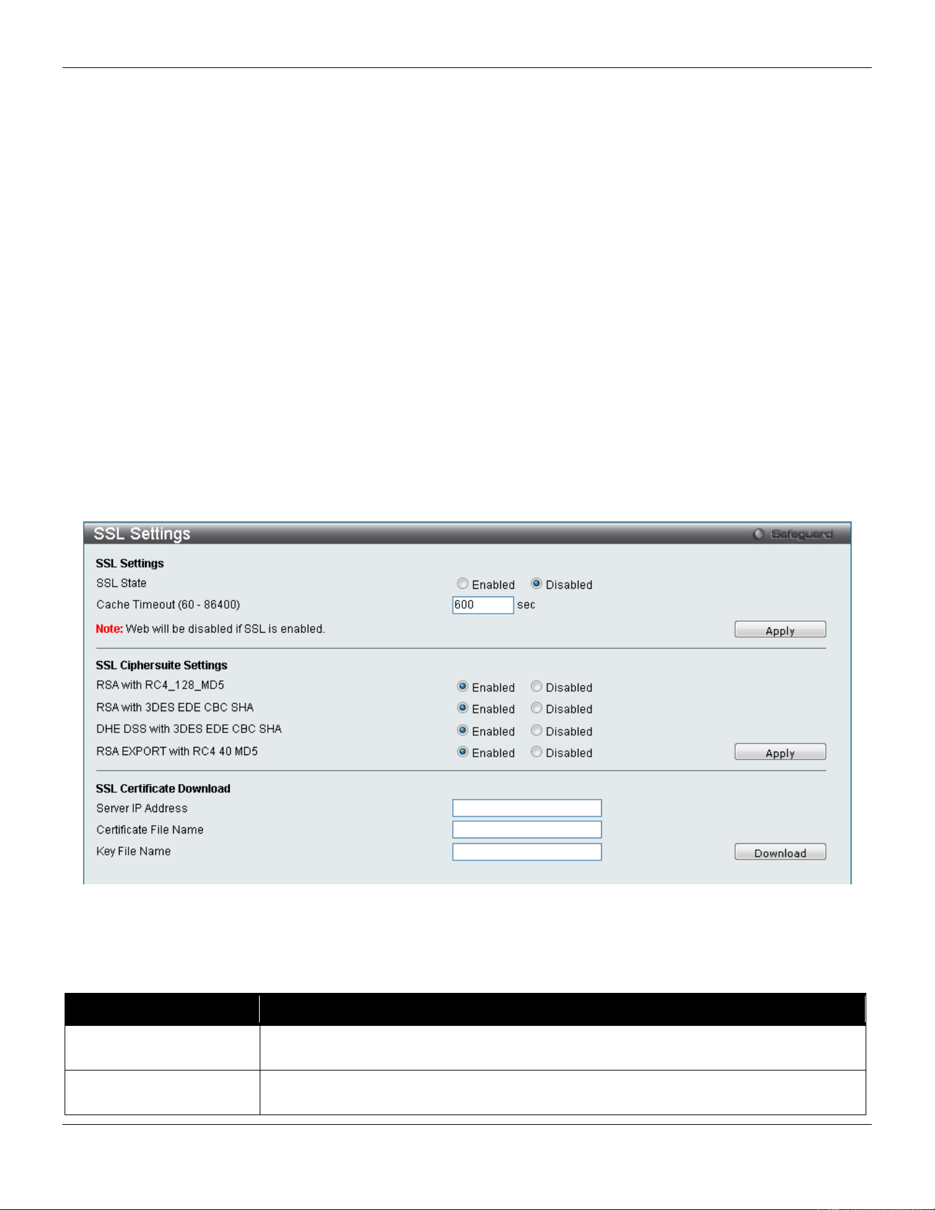
xStack® DGS-3420 Series Layer 2 Managed Stackable Gigabit Switch Web UI Reference Guide
348
a third source in a file form called a certificate. This function of the Switch cannot be executed without the presence
and implementation of the certificate file and can be downloaded to the Switch by utilizing a TFTP server. The Switch
supports SSLv3. Other versions of SSL may not be compatible with this Switch and may cause problems upon
authentication and transfer of messages from client to host.
The SSL Settings window located on the next page will allow the user to enable SSL on the Switch and implement any
one or combination of listed cipher suites on the Switch. A cipher suite is a security string that determines the exact
cryptographic parameters, specific encryption algorithms and key sizes to be used for an authentication session. The
Switch possesses four possible cipher suites for the SSL function, which are all enabled by default. To utilize a
particular cipher suite, disable the unwanted cipher suites, leaving the desired one for authentication.
When the SSL function has been enabled, the web will become disabled. To manage the Switch through the web
based management while utilizing the SSL function, the web browser must support SSL encryption and the header of
the URL must begin with https://. (Ex. https://xx.xx.xx.xx) Any other method will result in an error and no access can be
authorized for the web-based management.
Users can download a certificate file for the SSL function on the Switch from a TFTP server. The certificate file is a
data record used for authenticating devices on the network. It contains information on the owner, keys for
authentication and digital signatures. Both the server and the client must have consistent certificate files for optimal use
of the SSL function. The Switch only supports certificate files with .der file extensions. Currently, the Switch comes with
a certificate pre-loaded though the user may need to download more, depending on user circumstances.
To view this window, click Security > SSL Settings as shown below:
Figure 8-77 SSL Settings window
To set up the SSL function on the Switch, configure the parameters in the SSL Settings section described.
The fields that can be configured are described below:
Parameter Description
SSL Status
Use the radio buttons to enable or disable the SSL status on the Switch. The default is
Disabled.
Cache Timeout (60-
86400)
This field will set the time between a new key exchange between a client and a host
using the SSL function. A new SSL session is established every time the client and

xStack® DGS-3420 Series Layer 2 Managed Stackable Gigabit Switch Web UI Reference Guide
349
host go through a key exchange. Specifying a longer timeout will allow the SSL
session to reuse the master key on future connections with that particular host,
therefore speeding up the negotiation process. The default setting is 600 seconds.
Click the Apply button to accept the changes made.
To set up the SSL cipher suite function on the Switch, configure the parameters in the SSL Cipher suite Settings
section described below:
Parameter Description
RSA with RC4_128_MD5
This cipher suite combines the RSA key exchange, stream cipher RC4 encryption with
128-bit keys and the MD5 Hash Algorithm. Use the radio buttons to enable or disable
this cipher suite. This field is Enabled by default.
RSA with 3DES EDE
CBC SHA
This cipher suite combines the RSA key exchange, CBC Block Cipher 3DES_EDE
encryption and the SHA Hash Algorithm. Use the radio buttons to enable or disable
this cipher suite. This field is Enabled by default.
DHS DSS with 3DES
EDE CBC SHA
This cipher suite combines the DSA Diffie Hellman key exchange, CBC Block Cipher
3DES_EDE encryption and SHA Hash Algorithm. Use the radio buttons to enable or
disable this cipher suite. This field is Enabled by default.
RSA EXPORT with RC4
40 MD5
This cipher suite combines the RSA Export key exchange and stream cipher RC4
encryption with 40-bit keys. Use the radio buttons to enable or disable this cipher suite.
This field is Enabled by default.
Click the Apply button to accept the changes made.
To download SSL certificates, configure the parameters in the SSL Certificate Download section described below.
Parameter Description
Server IP Address
Enter the IPv4 address of the TFTP server where the certificate files are located.
Certificate File Name
Enter the path and the filename of the certificate file to download. This file must have
a .der extension. (Ex. c:/cert.der)
Key File Nam
Enter the path and the filename of the key file to download. This file must have a .der
extension (Ex. c:/pkey.der)
Click the Download button to download the SSL certificate based on the information entered.
NOTE: Certain implementations concerning the function and configuration of SSL are not available on the
web-based management of this Switch and need to be configured using the command line
interface.
NOTE: Enabling the SSL command will disable the web-based switch management. To log on to the
Switch again, the header of the URL must begin with https://. Entering anything else into the
address field of the web browser will result in an error and no authentication will be granted.
SSL Certification Settings
This window is used to configure the SSL certification settings
To view this window, click Security > SSL > SSL Certification Settings as shown below:
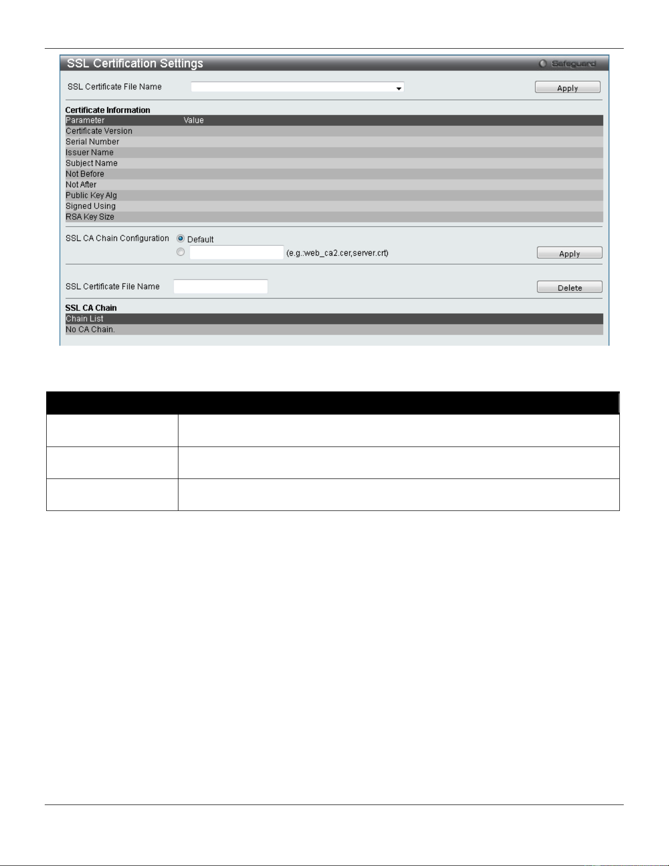
xStack® DGS-3420 Series Layer 2 Managed Stackable Gigabit Switch Web UI Reference Guide
350
Figure 8-78 SSL Certification Settings window
The fields that can be configured are described below:
Parameter Description
SSL Certification File
Name
Use the drop-down menu to select the SSL Certification File Name.
SSL CA Chain
Configuration
Enter the chain of certifications on the Switch. Click the Default button to use all the
certificates which were downloaded to the Switch to constitute a certificate chain.
SSL Certificate File
Name
Enter an SSL certificate file name to be deleted.
Click the Apply button to accept the changes made for each individual section.
Click the Delete button to remove the specific entry.
SSH
SSH is an abbreviation of Secure Shell, which is a program allowing secure remote login and secure network services
over an insecure network. It allows a secure login to remote host computers, a safe method of executing commands on
a remote end node, and will provide secure encrypted and authenticated communication between two non-trusted
hosts. SSH, with its array of unmatched security features is an essential tool in today’s networking environment. It is a
powerful guardian against numerous existing security hazards that now threaten network communications.
The steps required to use the SSH protocol for secure communication between a remote PC (the SSH client) and the
Switch (the SSH server) are as follows:
1 Create a user account with admin-level access using the User Accounts window. This is identical to creating
any other admin-level User Account on the Switch, including specifying a password. This password is used to
logon to the Switch, once a secure communication path has been established using the SSH protocol.
2 Configure the User Account to use a specified authorization method to identify users that are allowed to
establish SSH connections with the Switch using the SSH User Authentication Mode window. There are
three choices as to the method SSH will use to authorize the user, which are Host Based, Password, and
Public Key.
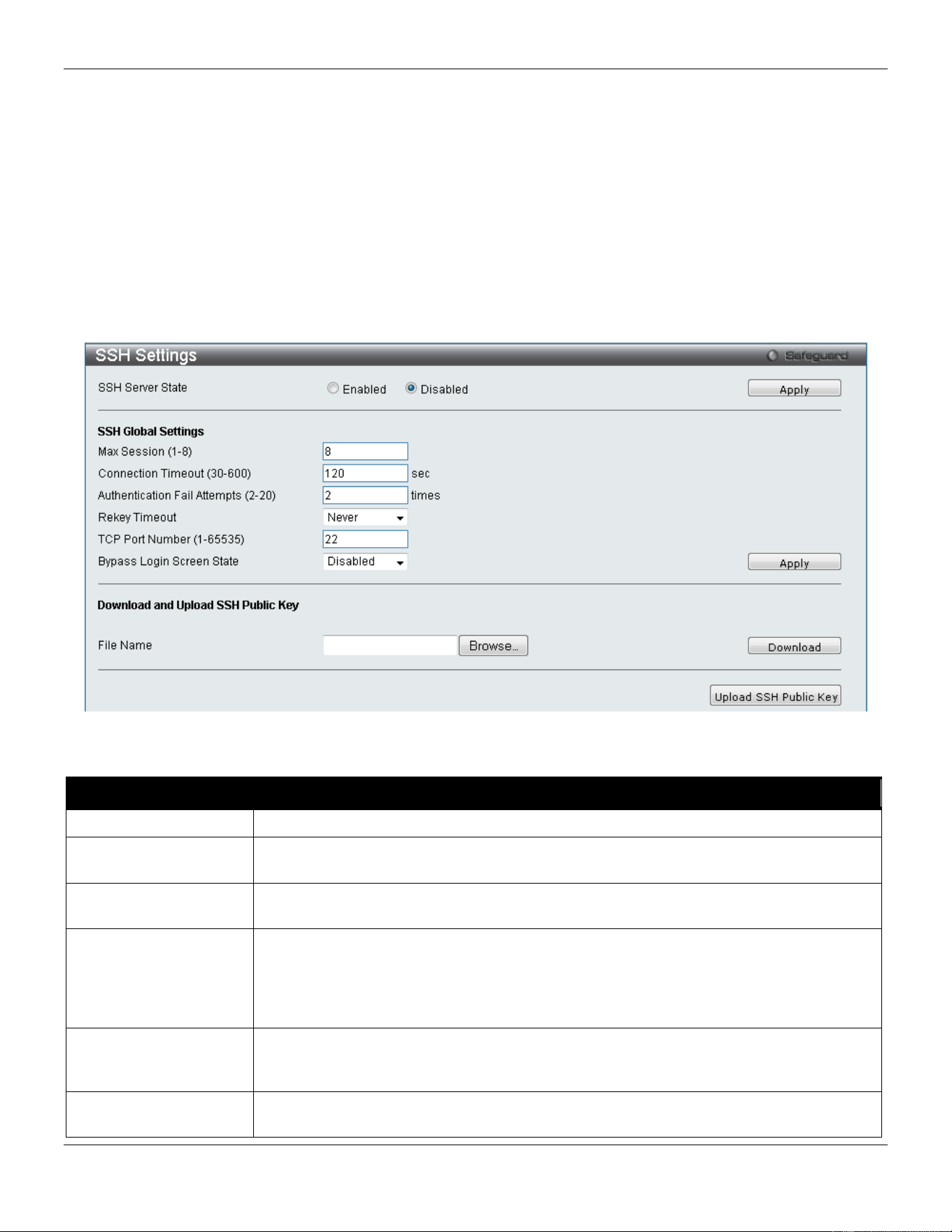
xStack® DGS-3420 Series Layer 2 Managed Stackable Gigabit Switch Web UI Reference Guide
351
3 Configure the encryption algorithm that SSH will use to encrypt and decrypt messages sent between the SSH
client and the SSH server, using the SSH Authentication Method and Algorithm Settings window.
4 Finally, enable SSH on the Switch using the SSH Configuration window.
After completing the preceding steps, a SSH Client on a remote PC can be configured to manage the Switch using a
secure, in band connection.
SSH Settings
Users can configure and view settings for the SSH server.
To view this window, click Security > SSH > SSH Settings as shown below:
Figure 8-79 SSH Settings window
The fields that can be configured are described below:
Parameter Description
SSH Server State
Use the radio buttons to enable or disable SSH on the Switch. The default is Disabled.
Max. Session (1-8)
Enter a value between 1 and 8 to set the number of users that may simultaneously
access the Switch. The default setting is 8.
Connection Timeout
(30-600)
Allows the user to set the connection timeout. The user may set a time between 30 and
600 seconds. The default setting is 120 seconds.
Authfail Attempts (2-
20)
Allows the Administrator to set the maximum number of attempts that a user may try to
log on to the SSH Server utilizing the SSH authentication. After the maximum number of
attempts has been exceeded, the Switch will be disconnected and the user must
reconnect to the Switch to attempt another login. The number of maximum attempts may
be set between 2 and 20. The default setting is 2.
Rekey Timeout
Use the drop-down menu to set the time period that the Switch will change the security
shell encryptions by using the drop-down menu. The available options are Never, 10
min, 30 min, and 60 min. The default setting is Never.
TCP Port Number (1-
65535)
Enter the TCP Port Number used for SSH. The default value is 22.
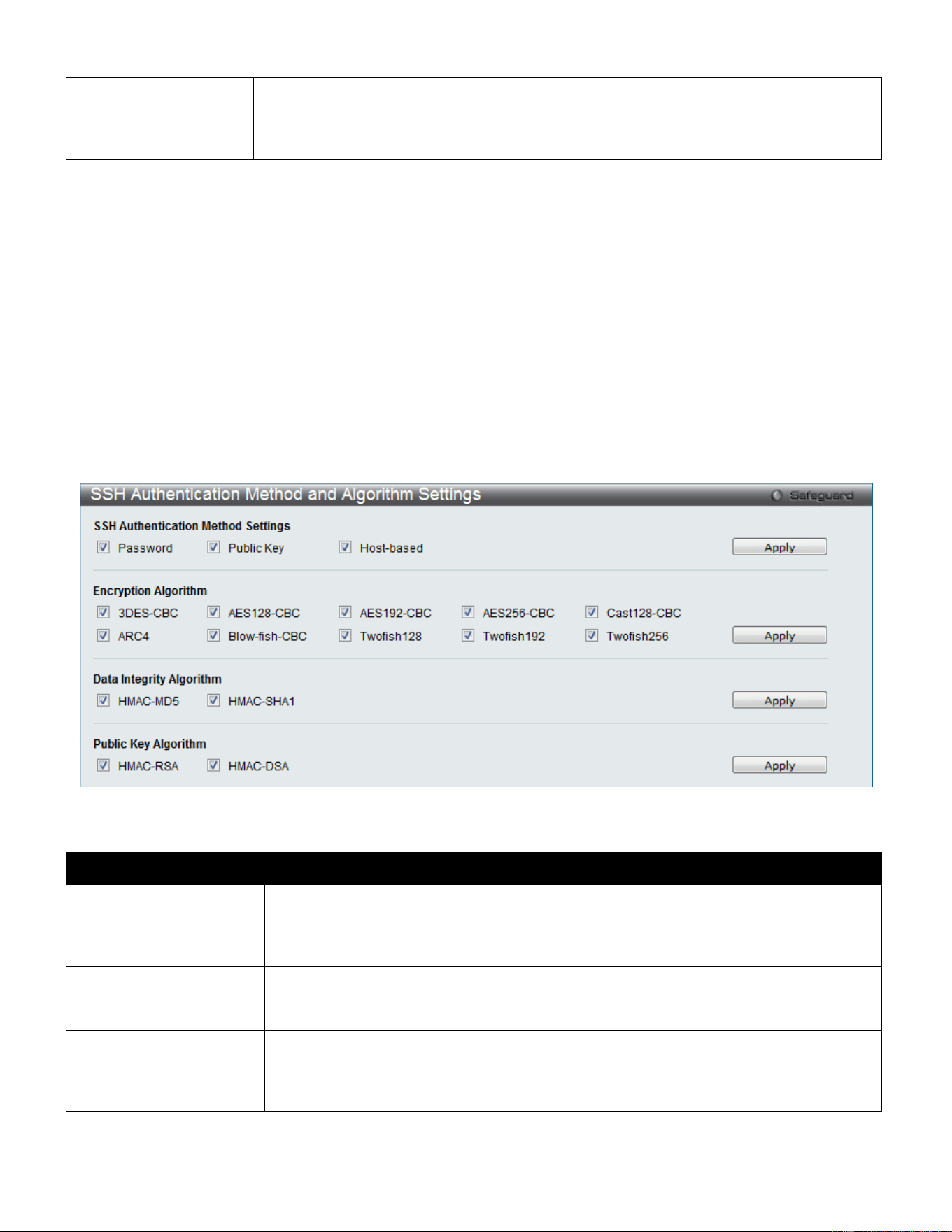
xStack® DGS-3420 Series Layer 2 Managed Stackable Gigabit Switch Web UI Reference Guide
352
Bypass Login Screen
State
Specifies to bypass the username and password login screen to avoid a secondary
authentication after using SSH public key authentication. If this method is specified, the
login user using SSH public key authentication can execute command directly with the
initial privilege level of the login user.
Click the Apply button to accept the changes made for each individual section.
On this page the user can also download the SSH public key file on client computer to the switch through TFTP
protocol. Click the Browse button to navigate to the key file, located on the client computer, and click the Download
button to initiate the download.
Click the Upload SSH Public Key button to upload the SSH public key file from the switch to a computer through the
TFTP protocol.
SSH Authentication Method and Algorithm Settings
Users can configure the desired types of SSH algorithms used for authentication encryption. There are three
categories of algorithms listed and specific algorithms of each may be enabled or disabled by ticking their
corresponding check boxes. All algorithms are enabled by default.
To view this window, click Security > SSH > SSH Authentication method and Algorithm Settings as shown below:
Figure 8-80 SSH Authentication Method and Algorithm Settings window
The fields that can be configured for SSH Authentication Mode are described below:
Parameter Description
Password
This may be enabled or disabled to choose if the administrator wishes to use a
password method, including AAA and locally configured password, based on the
configuration of the administrator, for authentication on the Switch. This parameter is
enabled by default.
Public Key
This may be enabled or disabled to choose if the administrator wishes to use a public
key configuration set on a SSH server, for authentication. This parameter is enabled by
default.
Host-based
This may be enabled or disabled to choose if the administrator wishes to use a host
computer for authentication. This parameter is intended for Linux users requiring SSH
authentication techniques and the host computer is running the Linux operating system
with a SSH program previously installed. This parameter is enabled by default.
Click the Apply button to accept the changes made.

xStack® DGS-3420 Series Layer 2 Managed Stackable Gigabit Switch Web UI Reference Guide
353
The fields that can be configured for the Encryption Algorithm are described below:
Parameter Description
3DES-CBC
Use the check box to enable or disable the Triple Data Encryption Standard encryption
algorithm with Cipher Block Chaining. The default is enabled.
AES128-CBC
Use the check box to enable or disable the Advanced Encryption Standard AES128
encryption algorithm with Cipher Block Chaining. The default is enabled.
AES192-CBC
Use the check box to enable or disable the Advanced Encryption Standard AES192
encryption algorithm with Cipher Block Chaining. The default is enabled.
AES256-CBC
Use the check box to enable or disable the Advanced Encryption Standard AES-256
encryption algorithm with Cipher Block Chaining. The default is enabled.
Cast128-CBC
Use the check box to enable or disable the Cast128 encryption algorithm with Cipher
Block Chaining. The default is enabled.
ARC4
Use the check box to enable or disable the Arcfour encryption algorithm with Cipher
Block Chaining. The default is enabled.
Blow-fish CBC
Use the check box to enable or disable the Blowfish encryption algorithm with Cipher
Block Chaining. The default is enabled.
Twofish128
Use the check box to enable or disable the twofish128 encryption algorithm. The
default is enabled.
Twofish192
Use the check box to enable or disable the twofish192 encryption algorithm. The
default is enabled.
Twofish256
Use the check box to enable or disable the twofish256 encryption algorithm. The
default is enabled.
Click the Apply button to accept the changes made.
The fields that can be configured for the Data Integrity Algorithm are described below:
Parameter Description
HMAC-MD5
Use the check box to enable or disable the HMAC (Hash for Message Authentication
Code) mechanism utilizing the MD5 Message Digest encryption algorithm. The default
is enabled.
HMAC-SHA1
Use the check box to enable or disable the HMAC (Hash for Message Authentication
Code) mechanism utilizing the Secure Hash algorithm. The default is enabled.
Click the Apply button to accept the changes made.
The fields that can be configured for the Public Key Algorithm are described below:
Parameter Description
HMAC-RSA
Use the check box to enable or disable the HMAC (Hash for Message Authentication
Code) mechanism utilizing the RSA encryption algorithm. The default is enabled.
HMAC-DSA
Use the check box to enable or disable the HMAC (Hash for Message Authentication
Code) mechanism utilizing the Digital Signature Algorithm (DSA) encryption. The
default is enabled.
Click the Apply button to accept the changes made.
SSH User Authentication List
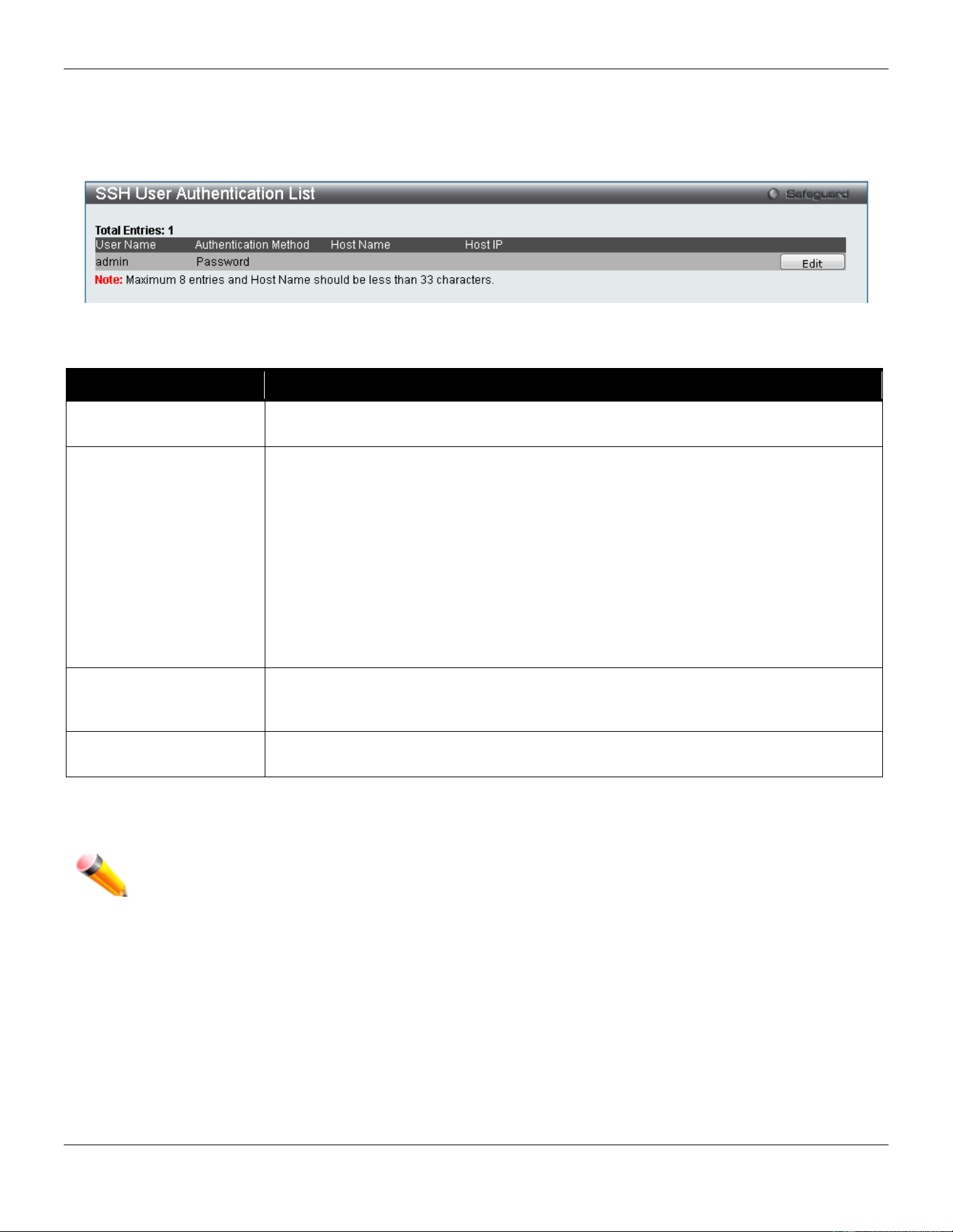
xStack® DGS-3420 Series Layer 2 Managed Stackable Gigabit Switch Web UI Reference Guide
354
Users can configure parameters for users attempting to access the Switch through SSH. In the window above, the
User Account “username” has been previously set using the User Accounts window in the Configuration folder. A
User Account MUST be set in order to set the parameters for the SSH user.
To view this window, click Security > SSH > SSH User Authentication List as shown below:
Figure 8-81 SSH User Authentication List window
The fields that can be configured or displayed are described below:
Parameter Description
User Name
A name of no more than 15 characters to identify the SSH user. This User Name must
be a previously configured user account on the Switch.
Authentication Method
The administrator may choose one of the following to set the authorization for users
attempting to access the Switch.
Host Based – This parameter should be chosen if the administrator wishes to use a
remote SSH server for authentication purposes. Choosing this parameter requires the
user to input the following information to identify the SSH user.
Password – This parameter should be chosen if the administrator wishes to use an
administrator-defined password for authentication. Upon entry of this parameter, the
Switch will prompt the administrator for a password, and then to re-type the password
for confirmation.
Public Key – This parameter should be chosen if the administrator wishes to use the
public key on a SSH server for authentication.
Host Name
Enter an alphanumeric string of no more than 32 characters to identify the remote SSH
user. This parameter is only used in conjunction with the Host Based choice in the
Auth. Mode field.
Host IP
Enter the corresponding IP address of the SSH user. This parameter is only used in
conjunction with the Host Based choice in the Auth. Mode field.
Click the Edit button to re-configure the specific entry.
Click the Apply button to accept the changes made.
NOTE: To set the SSH User Authentication Mode parameters on the Switch, a User Account must be
previously configured.
DoS Attack Prevention Settings
On this page, the user can configure the prevention of each DoS attacks. The packet matching will be done by
hardware. For a specific type of attack, the content of the packet will be matched against a specific pattern.
To view this window, click Security > DoS Attack Prevention Settings as shown below:
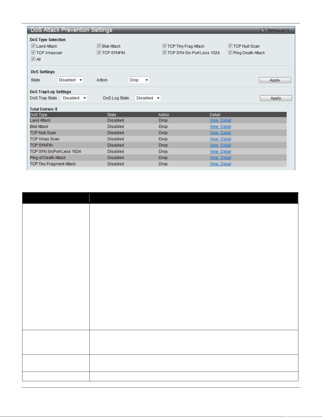
xStack® DGS-3420 Series Layer 2 Managed Stackable Gigabit Switch Web UI Reference Guide
355
Figure 8-82 DoS Attack Prevention Settings window
The fields that can be configured or displayed are described below:
Parameter Description
DoS Type Selection
Here the user can select the appropriate DoS Attack prevention types.
Land Attack - Specifies that the DoS attack prevention type will be set to prevent LAND
attacks.
Blat Attack - Specifies that the DoS attack prevention type will be set to prevent BLAT
attacks.
TCP Tiny Frag Attack - Specifies that the DoS attack prevention type will be set to
prevent TCP Tiny Frag attacks.
TCP Null Scan - Specifies that the DoS attack prevention type will be set to prevent
TCP Null Scan attacks.
TCP Xmascan - Specifies that the DoS attack prevention type will be set to prevent
TCP Xmas Scan attacks.
TCP SYNFIN - Specifies that the DoS attack prevention type will be set to prevent TCP
SYN FIN attacks.
TCP SYN Src Port Less 1024 - Specifies that the DoS attack prevention type will be
set to prevent TCP SYN Source Port Less 1024 attacks.
Ping Death Attack - Specifies that the DoS attack prevention type will be set to prevent
Ping of Death attacks.
all - Specifies that the DoS attack prevention type will be set to prevent all attacks.
State
Specifies the DoS Attack Prevention state.
Enable - Specifies that the DoS Attack Prevention state will be enabled.
Disable - Specifies that the DoS Attack Prevention state will be disabled.
Action
Specifies the action that the DoS Prevention function will take.
Drop - Specifies to drop all matched DoS attack packets.
DoS Trap State
This option is used to enable or disable the DoS prevention trap state.
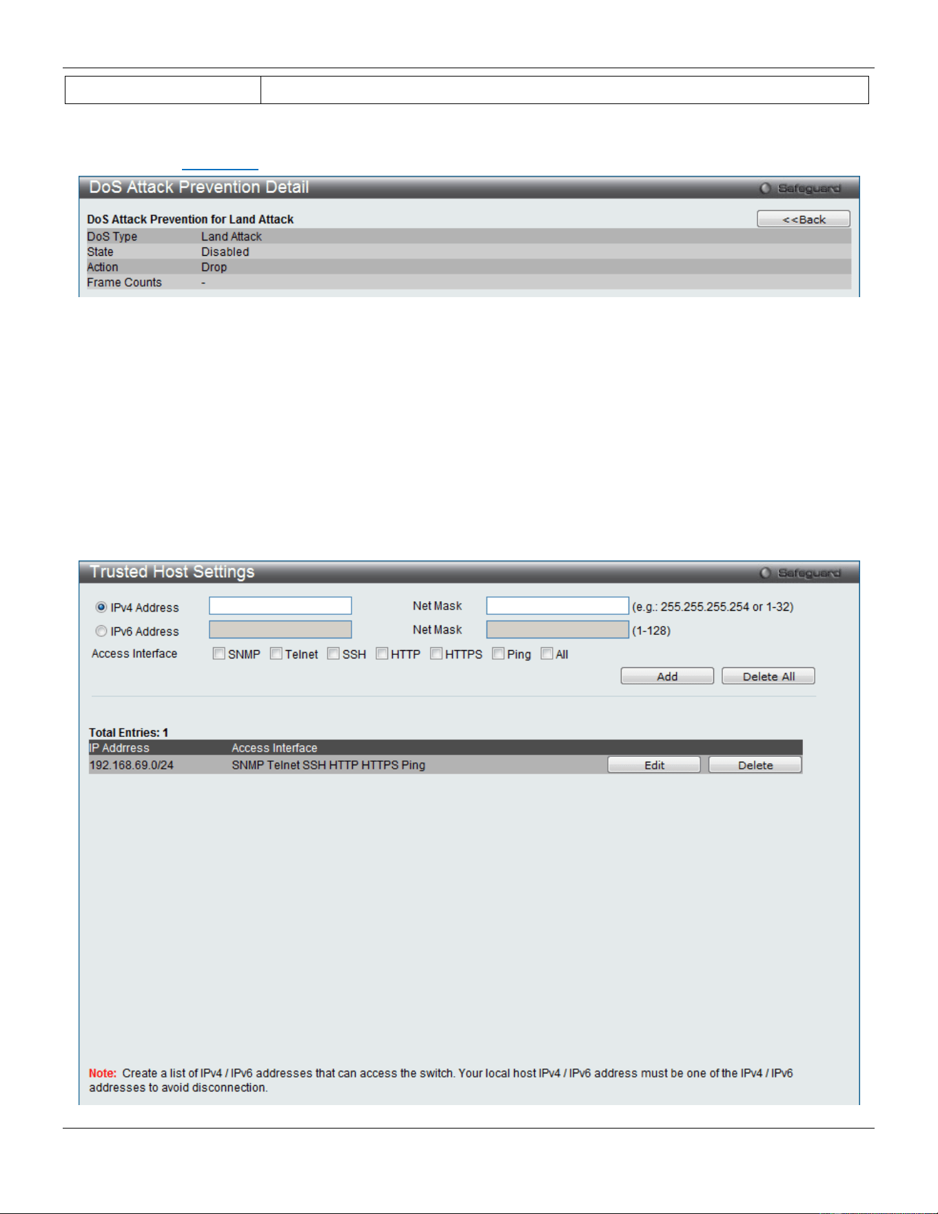
xStack® DGS-3420 Series Layer 2 Managed Stackable Gigabit Switch Web UI Reference Guide
356
DoS Log State
This option is used to enable or disable the DoS prevention log state.
Click the Apply button to accept the changes made.
After clicking the View Detail link next to the DoS Type displays, the following window will appear:
Figure 8-83 DoS Attack Prevention Detail window
Click the <<Back button to return to the previous page.
Trusted Host Settings
Up to thirty trusted host secure IP addresses or ranges may be configured and used for remote Switch management. It
should be noted that if one or more trusted hosts are enabled, the Switch will immediately accept remote instructions
from only the specified IP address or addresses. If you enable this feature, be sure to first enter the IP address of the
station you are currently using.
To view this window, click Security > Trusted Host Settings as shown below:
xStack® DGS-3420 Series Layer 2 Managed Stackable Gigabit Switch Web UI Reference Guide
357
Figure 8-84 Trusted Host window
When the user clicks the Edit button, one will be able to edit the service allowed to the selected host.
The fields that can be configured are described below:
Parameter Description
IPv4 Address
Enter an IPv4 address to add to the trusted host list.
IPv6 Address
Enter an IPv6 address to add to the trusted host list.
Net Mask
Enter a Net Mask address to add to the trusted host list.
Access Interface
Tick the check boxes to select services that will be allowed to the trusted host.
Click the Add button to add a new entry based on the information entered.
Click the Delete All button to remove all the entries listed.
Safeguard Engine Settings
Periodically, malicious hosts on the network will attack the Switch by utilizing packet flooding (ARP Storm) or other
methods. These attacks may increase the switch load beyond its capability. To alleviate this problem, the Safeguard
Engine function was added to the Switch’s software.
The Safeguard Engine can help the overall operability of the Switch by minimizing the workload of the Switch while the
attack is ongoing, thus making it capable to forward essential packets over its network in a limited bandwidth. The
Safeguard Engine has two operating modes that can be configured by the user, Strict and Fuzzy. In Strict mode, when
the Switch either (a) receives too many packets to process or (b) exerts too much memory, it will enter the Exhausted
mode. When in this mode, the Switch will drop all ARP and IP broadcast packets and packets from un-trusted IP
addresses for a calculated time interval. Every five seconds, the Safeguard Engine will check to see if there are too
many packets flooding the Switch. If the threshold has been crossed, the Switch will initially stop all ingress ARP and
IP broadcast packets and packets from un-trusted IP addresses for five seconds. After another five-second checking
interval arrives, the Switch will again check the ingress flow of packets. If the flooding has stopped, the Switch will
again begin accepting all packets. Yet, if the checking shows that there continues to be too many packets flooding the
Switch, it will stop accepting all ARP and IP broadcast packets and packets from un-trusted IP addresses for double
the time of the previous stop period. This doubling of time for stopping these packets will continue until the maximum
time has been reached, which is 320 seconds and every stop from this point until a return to normal ingress flow would
be 320 seconds. For a better understanding, please examine the following example of the Safeguard Engine.
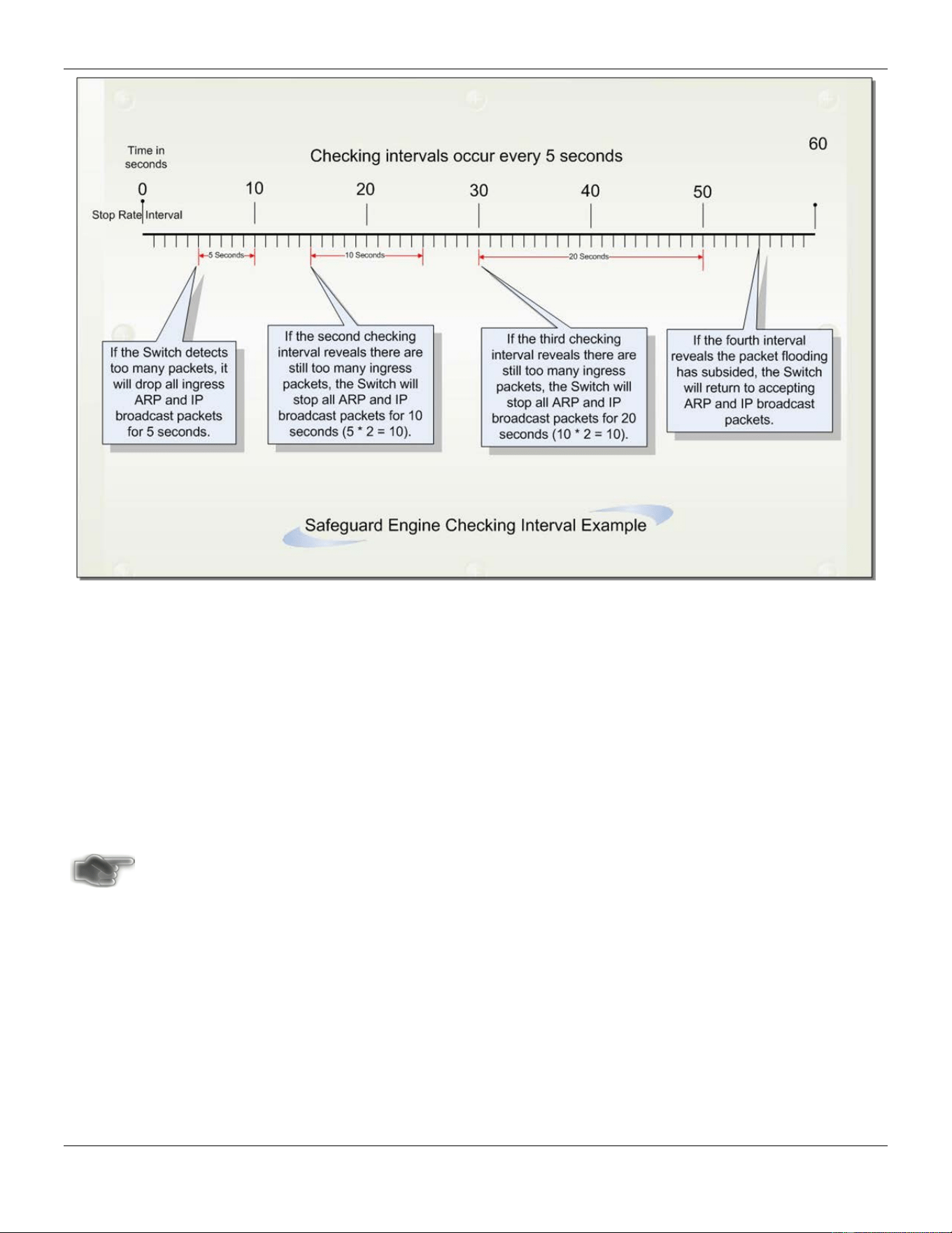
xStack® DGS-3420 Series Layer 2 Managed Stackable Gigabit Switch Web UI Reference Guide
358
Figure 8-85 Mapping QoS on the Switch
For every consecutive checking interval that reveals a packet flooding issue, the Switch will double the time it will
discard ingress ARP and IP broadcast packets and packets from the illegal IP addresses. In the example above, the
Switch doubled the time for dropping ARP and IP broadcast packets when consecutive flooding issues were detected
at 5-second intervals. (First stop = 5 seconds, second stop = 10 seconds, third stop = 20 seconds) Once the flooding is
no longer detected, the wait period for dropping ARP and IP broadcast packets will return to 5 seconds and the
process will resume.
In Fuzzy mode, once the Safeguard Engine has entered the Exhausted mode, the Safeguard Engine will decrease the
packet flow by half. After returning to Normal mode, the packet flow will be increased by 25%. The switch will then
return to its interval checking and dynamically adjust the packet flow to avoid overload of the Switch.
NOTICE: When Safeguard Engine is enabled, the Switch will allot bandwidth to various traffic flows (ARP,
IP) using the FFP (Fast Filter Processor) metering table to control the CPU utilization and limit
traffic. This may limit the speed of routing traffic over the network.
Users can enable the Safeguard Engine or configure advanced Safeguard Engine settings for the Switch.
To view this window, click Security > Safeguard Engine Settings as shown below:
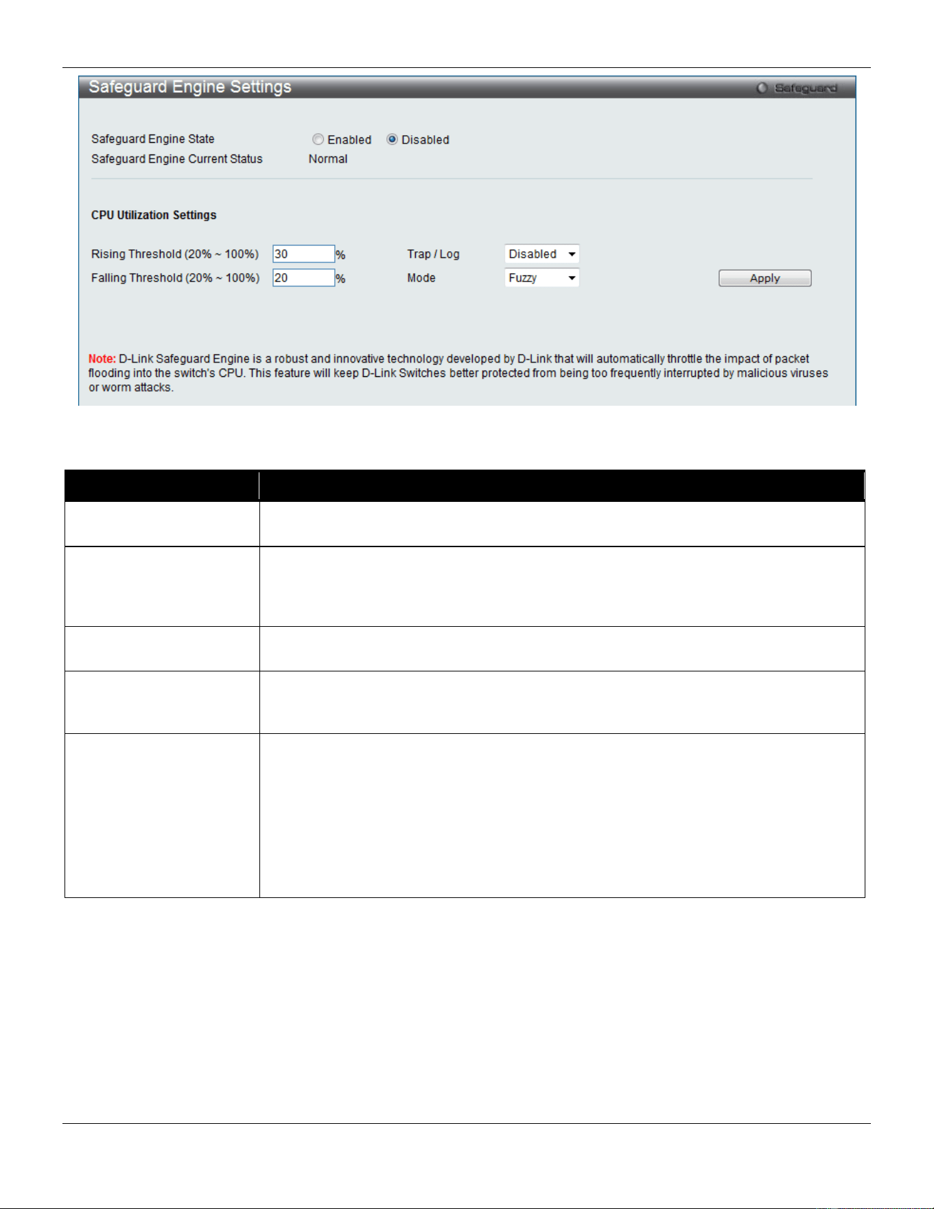
xStack® DGS-3420 Series Layer 2 Managed Stackable Gigabit Switch Web UI Reference Guide
359
Figure 8-86 Safeguard Engine Settings window
The fields that can be configured are described below:
Parameter Description
Safeguard Engine State
Use the radio button to globally enable or disable Safeguard Engine settings for the
Switch.
Rising Threshold (20% -
100%)
Used to configure the acceptable level of CPU utilization before the Safeguard Engine
mechanism is enabled. Once the CPU utilization reaches this percentage level, the
Switch will move into Exhausted mode, based on the parameters provided in this
window.
Falling Threshold (20% -
100%)
Used to configure the acceptable level of CPU utilization as a percentage, where the
Switch leaves the Safeguard Engine state and returns to normal mode.
Trap / Log
Use the drop-down menu to enable or disable the sending of messages to the device’s
SNMP agent and switch log once the Safeguard Engine has been activated by a high
CPU utilization rate.
Mode
Used to select the type of Safeguard Engine to be activated by the Switch when the
CPU utilization reaches a high rate. The user may select:
Fuzzy – If selected, this function will instruct the Switch to minimize the IP and ARP
traffic flow to the CPU by dynamically allotting an even bandwidth to all traffic flows.
Strict – If selected, this function will stop accepting all ARP packets not intended for the
Switch, and will stop receiving all unnecessary broadcast IP packets, until the storm
has subsided.
The default setting is Fuzzy mode.
Click the Apply button to accept the changes made.
SFTP Server Settings
This window is used to enable, disable, and configure the SFTP function globally. SFTP over SSH2 is a remotely
secure file transfer protocol providing security on all file operations. SFTP server runs as a subsystem of SSH server.
SSH server is required to be enabled before enabling SFTP server.
To view this window, click Security > SFTP Server Settings as shown below:
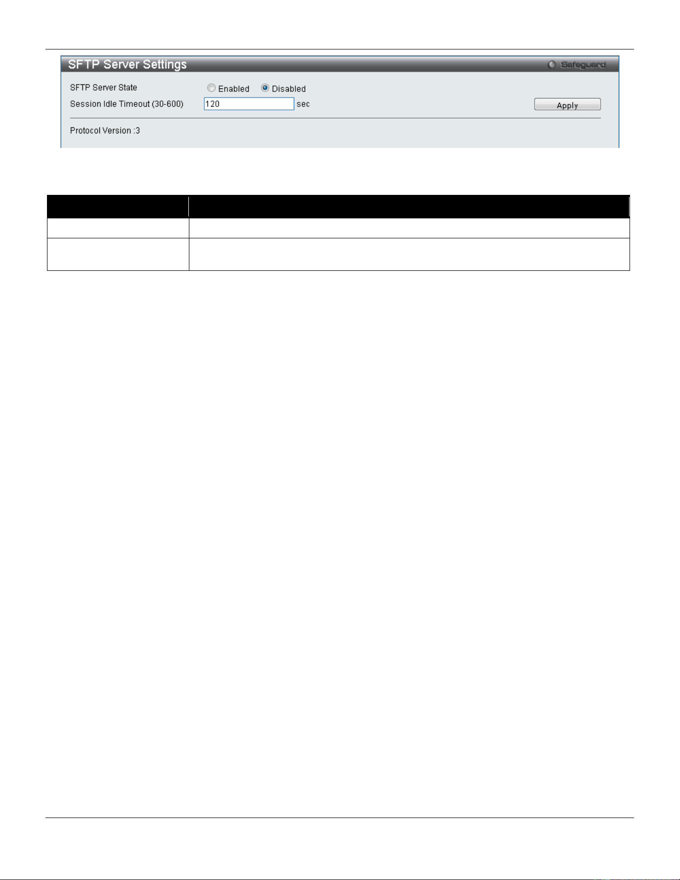
xStack® DGS-3420 Series Layer 2 Managed Stackable Gigabit Switch Web UI Reference Guide
360
Figure 8-87 SFTP Server Settings window
The fields that can be configured are described below:
Parameter Description
SFTP Server State
Select to enable or disable the SFTP server state here.
Session Idle Timeout
(30-600)
Enter the SFTP server session idle timeout value used here. This value must be
between 30 and 600 seconds. The default value is 120 seconds.
Click the Apply button to accept the changes made.
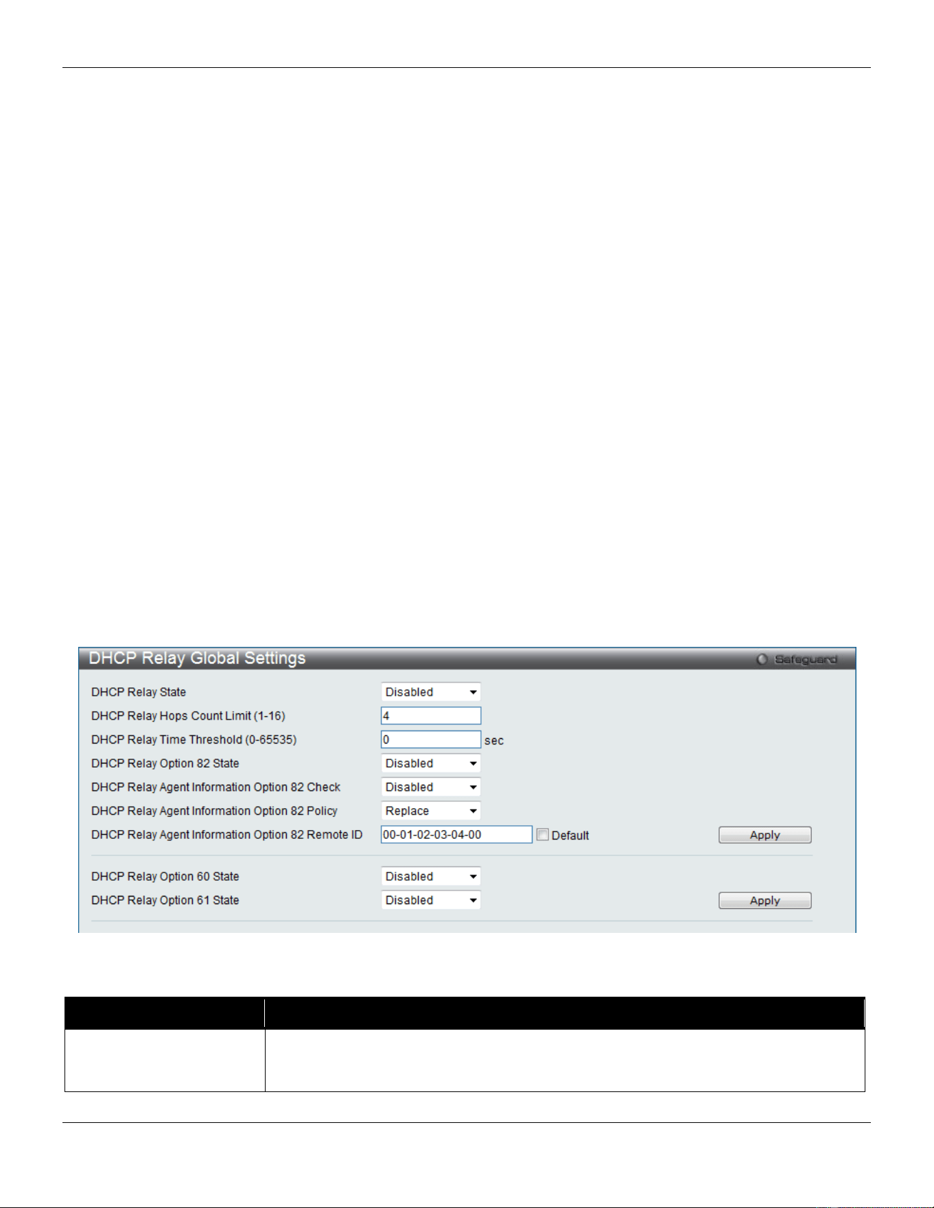
xStack® DGS-3420 Series Layer 2 Managed Stackable Gigabit Switch Web UI Reference Guide
361
Chapter 9 Network Application
DHCP
DNS
DNS Resolver
RCP Server Settings
SMTP Settings
SNTP
UDP
Flash File System Settings
DHCP
DHCP Relay
DHCP Relay Global Settings
Users can enable and configure DHCP Relay Global Settings. The relay hops count limit allows the maximum number
of hops (routers) that the DHCP messages can be relayed through to be set. The DHCP packet will be dropped when
the relay hop count in the received packet is equal to or greater than this setting. The range is between 1 and 16 hops,
with a default value of 4. The relay time threshold sets the minimum time (in seconds) that the Switch will wait before
forwarding a BOOTREQUEST packet. If the value in the seconds’ field of the packet is less than the relay time
threshold, the packet will be dropped. The range is between 0 and 65,535 seconds, with a default value of 0 seconds.
To view this window, click Network Application > DHCP > DHCP Relay > DHCP Relay Global Settings as shown
below:
Figure 9-1 DHCP Relay Global Settings window
The fields that can be configured are described below:
Parameter Description
DHCP Relay State This field can be toggled between Enabled and Disabled using the drop-down menu.
It is used to enable or disable the DHCP Relay service on the Switch. The default is
Disabled.

xStack® DGS-3420 Series Layer 2 Managed Stackable Gigabit Switch Web UI Reference Guide
362
DHCP Relay Hops Count
Limit (1-16)
This field allows an entry between 1 and 16 to define the maximum number of router
hops DHCP messages can be forwarded. The default hop count is 4.
DHCP Relay Time
Threshold (0-65535)
Allows an entry between 0 and 65535 seconds, and defines the maximum time limit
for routing a DHCP packet. If a value of 0 is entered, the Switch will not process the
value in the seconds’ field of the DHCP packet. If a non-zero value is entered, the
Switch will use that value, along with the hop count to determine whether to forward a
given DHCP packet.
DHCP Relay Option 82
State
This field can be toggled between Enabled and Disabled using the drop-down menu.
It is used to enable or disable the DHCP Relay Agent Information Option 82 on the
Switch. The default is Disabled.
Enabled –When this field is toggled to Enabled, the relay agent will insert and remove
DHCP relay information (option 82 field) in messages between DHCP servers and
clients. When the relay agent receives the DHCP request, it adds the option 82
information, and the IP address of the relay agent (if the relay agent is configured), to
the packet. Once the option 82 information has been added to the packet it is sent on
to the DHCP server. When the DHCP server receives the packet, if the server is
capable of option 82, it can implement policies like restricting the number of IP
addresses that can be assigned to a single remote ID or circuit ID. Then the DHCP
server echoes the option 82 field in the DHCP reply. The DHCP server unicasts the
reply back to the relay agent if the request was relayed to the server by the relay
agent. The switch verifies that it originally inserted the option 82 data. Finally, the relay
agent removes the option 82 field and forwards the packet to the switch port that
connects to the DHCP client that sent the DHCP request.
Disabled- When the field is toggled to Disabled, the relay agent will not insert and
remove DHCP relay information (option 82 field) in messages between DHCP servers
and clients, and the check and policy settings will have no effect.
DHCP Relay Agent
Information Option 82
Check
This field can be toggled between Enabled and Disabled using the drop-down menu.
It is used to enable or disable the Switch’s ability to check the validity of the packet’s
option 82 field.
Enabled – When the field is toggled to Enabled, the relay agent will check the validity
of the packet’s option 82 field. If the Switch receives a packet that contains the option
82 field from a DHCP client, the Switch drops the packet because it is invalid. In
packets received from DHCP servers, the relay agent will drop invalid messages.
Disabled – When the field is toggled to Disabled, the relay agent will not check the
validity of the packet’s option 82 field.
DHCP Relay Agent
Information Option 82
Policy
This field can be toggled between Replace, Drop, and Keep by using the drop-down
menu. It is used to set the Switch’s policy for handling packets when the DHCP Relay
Agent Information Option 82 Check is set to
Disabled. The default is Replace.
Replace – The option 82 field will be replaced if the option 82 field already exists in
the packet received from the DHCP client.
Drop – The packet will be dropped if the option 82 field already exists in the packet
received from the DHCP client.
Keep – The option 82 field will be retained if the option 82 field already exists in the
packet received from the DHCP client.
DHCP Relay Agent
Information Option 82
Remote ID
Enter the DHCP Relay Agent Information Option 82 Remote ID.
DHCP Relay Option 60
State
Use the drop-down menu to enable or disable the use of the DHCP Relay Option 60
State feature.
DHCP Relay Option 61
State
Use the drop-down menu to enable or disable the use of the DHCP Relay Option 61
State feature.
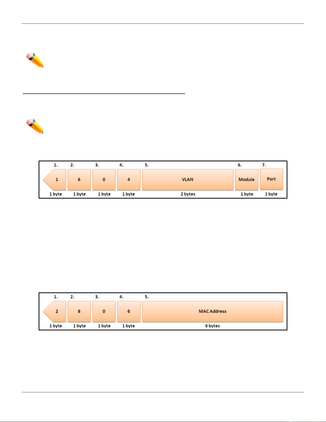
xStack® DGS-3420 Series Layer 2 Managed Stackable Gigabit Switch Web UI Reference Guide
363
Click the Apply button to accept the changes made for each individual section.
NOTE: If the Switch receives a packet that contains the option 82 field from a DHCP client and the
information-checking feature is enabled, the Switch drops the packet because it is invalid.
However, in some instances, users may configure a client with the option 82 field. In this situation,
disable the information check feature so that the Switch does not drop the option 82 field from the
packet. Users may configure the action that the Switch takes when it receives a packet with
existing option 82 information by configuring the DHCP Agent Information Option 82 Policy.
The Implementation of DHCP Relay Agent Information Option 82
The DHCP Relay Option 82 command configures the DHCP relay agent information option 82 setting of the Switch.
The formats for the circuit ID sub-option and the remote ID sub-option are as follows:
NOTE: For the circuit ID sub-option of a standalone switch, the module field is always zero.
Circuit ID sub-option format:
Figure 9-2 Circuit ID Sub-option Format
1 Sub-option type
2 Length
3 Circuit ID type
4 Length
5 VLAN: The incoming VLAN ID of DHCP client packet.
6 Module: For a standalone switch, the Module is always 0; for a stackable switch, the Module is the Unit ID.
7 Port: The incoming port number of the DHCP client packet, the port number starts from 1.
Remote ID sub-option format:
Figure 9-3 Remote ID Sub-option Format
1 Sub-option type
2 Length
3 Remote ID type
4 Length
5 MAC address: The Switch’s system MAC address.
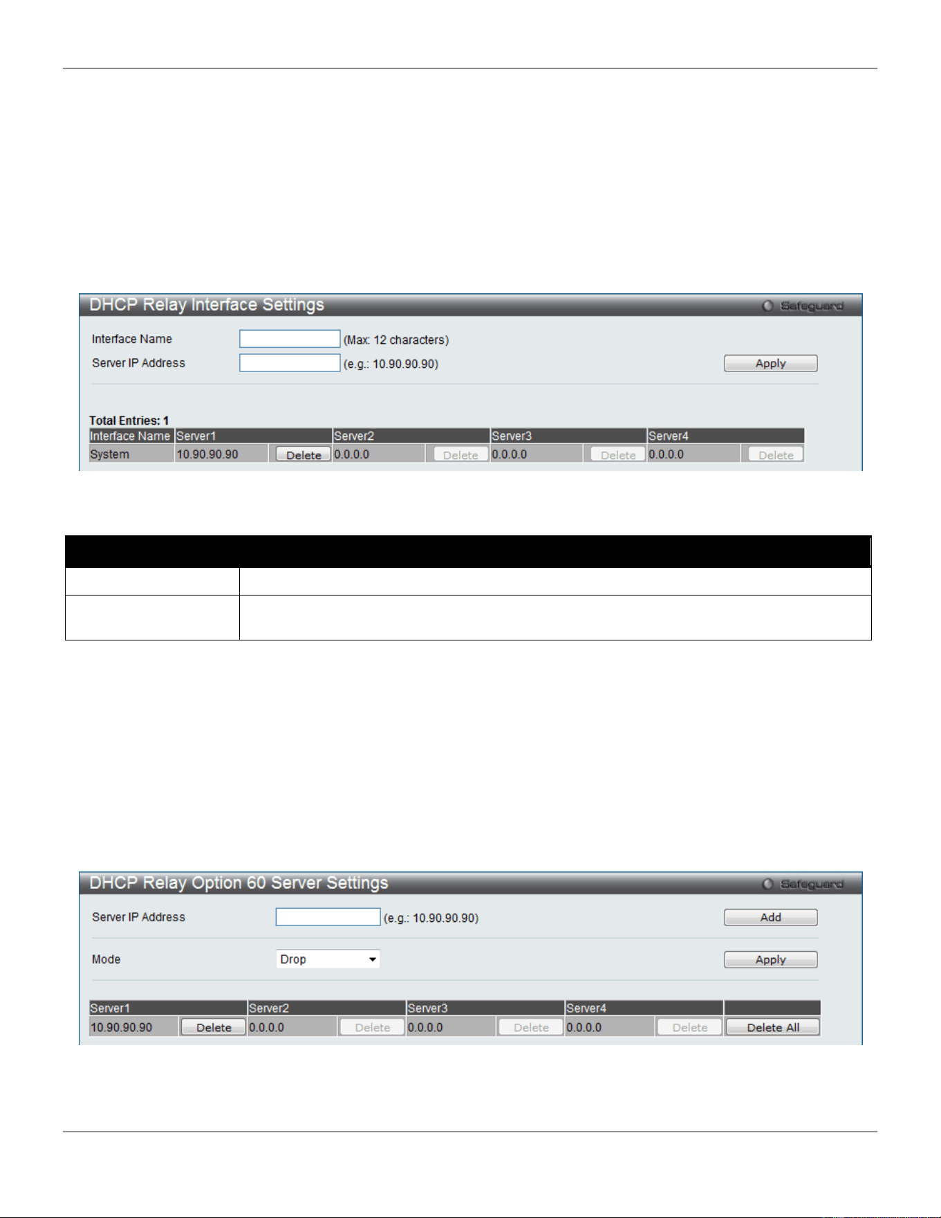
xStack® DGS-3420 Series Layer 2 Managed Stackable Gigabit Switch Web UI Reference Guide
364
DHCP Relay Interface Settings
Users can set up a server, by IP address, for relaying DHCP information to the Switch. The user may enter a
previously configured IP interface on the Switch that will be connected directly to the DHCP client using this window.
Properly configured settings will be displayed in the DHCP Relay Interface Table at the bottom of the window, once the
user clicks the Apply button. The user may add up to four server IPs per IP interface on the Switch. Entries may be
deleted by clicking the corresponding Delete button.
To view this window, click Network Application > DHCP > DHCP Relay > DHCP Relay Interface Settings as shown
below:
Figure 9-4 DHCP Relay Interface Settings window
The fields that can be configured are described below:
Parameter Description
Interface Name
The IP interface on the Switch that will be connected directly to the client.
Server IP Address
Enter the IP address of the DHCP server. Up to four server IPs can be configured per IP
Interface.
Click the Apply button to accept the changes made.
DHCP Relay Option 60 Server Settings
The DHCP Option 60 is a Vendor class identifier. If this feature is enabled, the Switch will check the Option 60 from the
DHCP client and then decide to which DHCP server it should be forwarded to. The forwarding rule can be configured in
this Switch. On this page the user can configure the DHCP relay Option 60 server parameters.
To view this window, click Network Application > DHCP > DHCP Relay > DHCP Relay Option 60 Server Settings
as shown below:
Figure 9-5 DHCP Relay Option 60 Server Settings window
The fields that can be configured are described below:
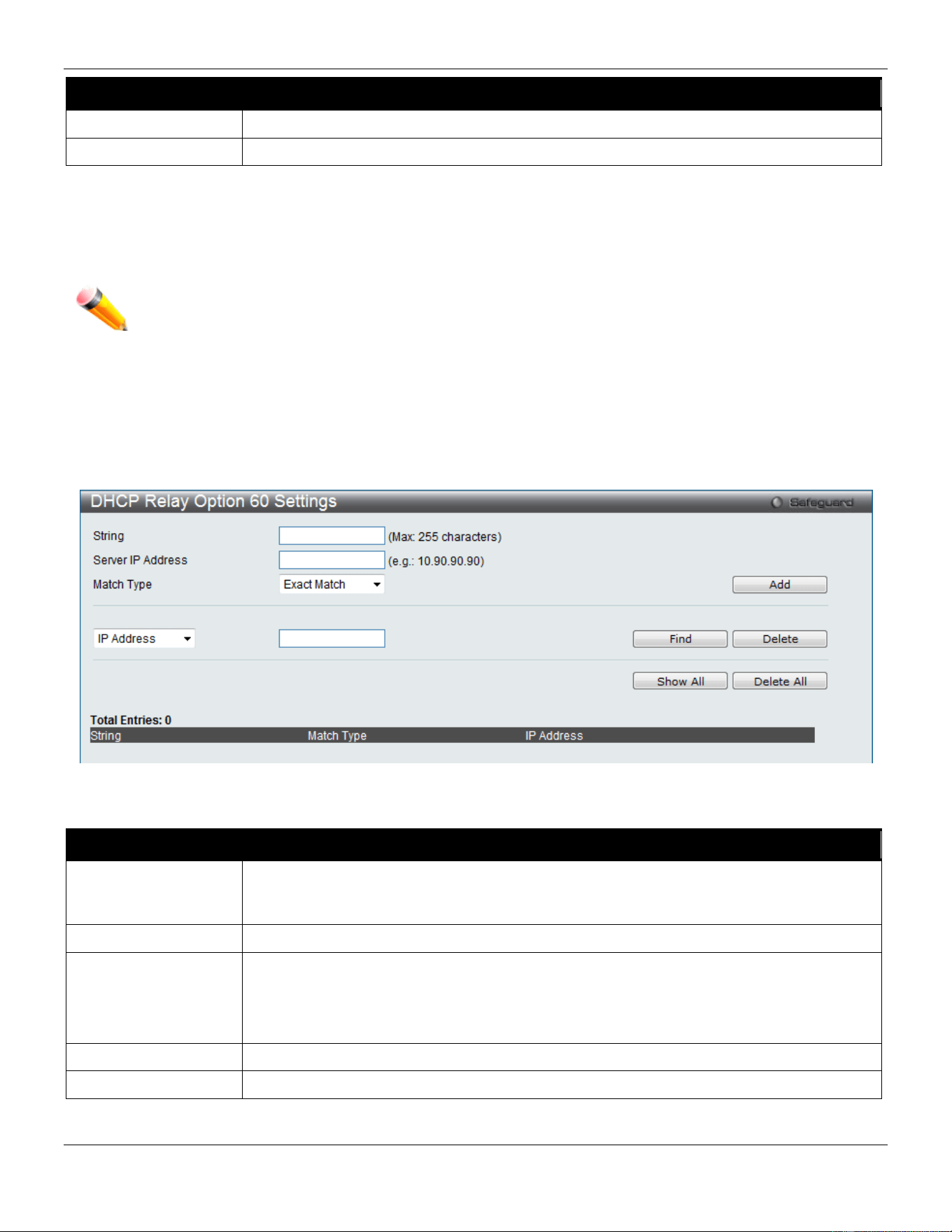
xStack® DGS-3420 Series Layer 2 Managed Stackable Gigabit Switch Web UI Reference Guide
365
Parameter Description
Server IP Address
Enter the DHCP Relay Option 60 Server Relay IP Address.
Mode
Use the drop-down menu to select the DHCP Relay Option 60 Server mode.
Click the Add button to add a new entry based on the information entered.
Click the Apply button to accept the changes made.
Click the Delete button to remove the specific entry.
Click the Delete All button to remove all the entries listed.
NOTE: When there is no matching server found for the packet based on option 60, the relay servers will
be determined by the default relay server setting.
DHCP Relay Option 60 Settings
This option decides whether the DHCP Relay will process the DHCP option 60 or not
To view this window, click Network Application > DHCP > DHCP Relay > DHCP Relay Option 60 Settings as
shown below:
Figure 9-6 DHCP Relay Option 60 Settings window
The fields that can be configured are described below:
Parameter Description
String
Enter the DHCP Relay Option 60 String value. Different strings can be specified for the
same relay server, and the same string can be specified with multiple relay servers. The
system will relay the packet to all the matching servers.
Server IP Address
Enter the DHCP Relay Option 60 Server IP address.
Match Type
Enter the DHCP Relay Option 60 Match Type value.
Exact Match – The option 60 string in the packet must full match with the specified string.
Partial Match – The option 60 string in the packet only need partial match with the
specified string.
IP Address
Enter the DHCP Relay Option 60 IP address.
String
Enter the DHCP Relay Option 60 String value.
Click the Add button to add a new entry based on the information entered.
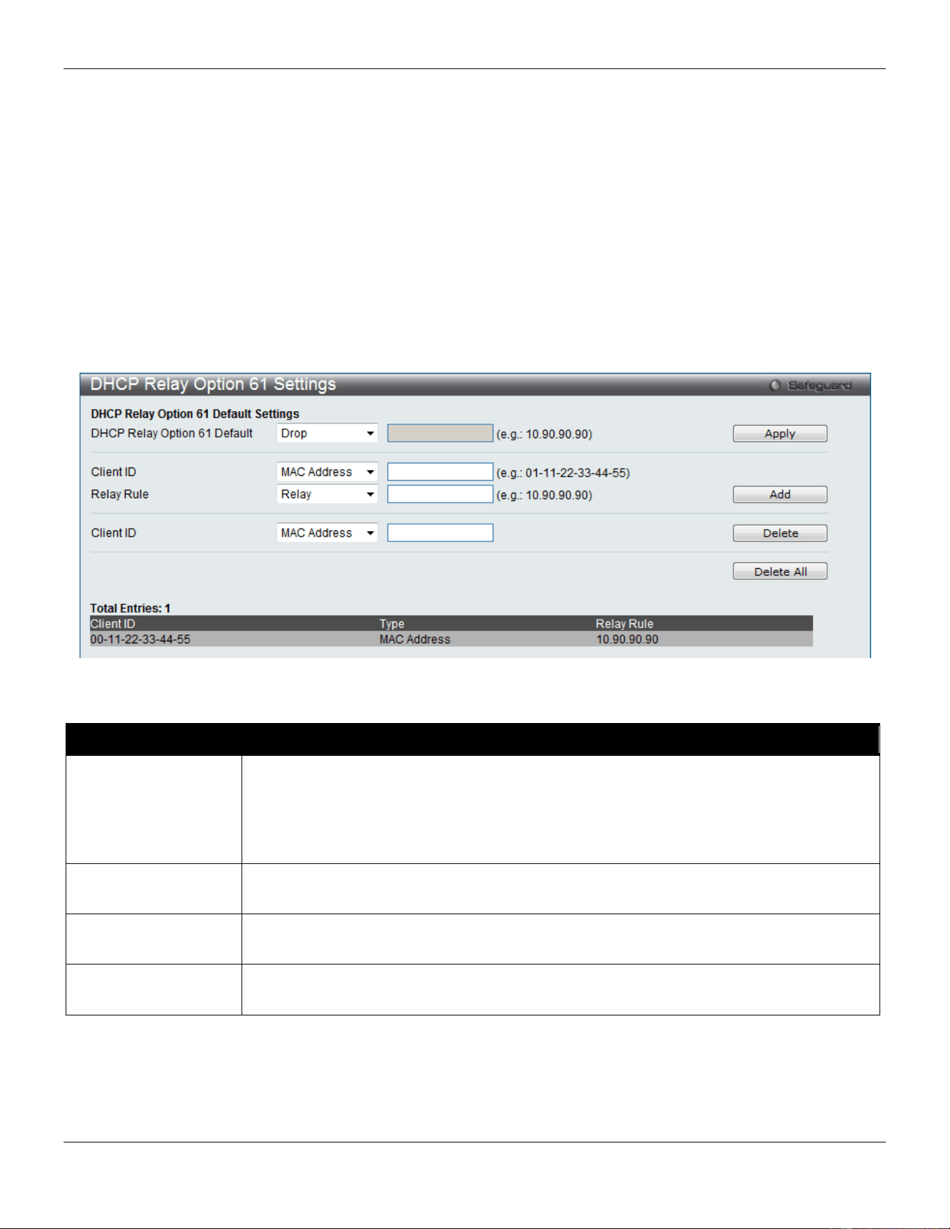
xStack® DGS-3420 Series Layer 2 Managed Stackable Gigabit Switch Web UI Reference Guide
366
Click the Find button to locate a specific entry based on the information entered.
Click the Delete button to remove the specific entry based on the information entered.
Click the Show All button to display all the existing entries.
Click the Delete All button to remove all the entries listed.
Click the Delete button to remove the specific entry.
DHCP Relay Option 61 Settings
If this feature is enabled, the Switch will check the Option 61 from the DHCP client and then decide to forward a
specific server or to drop it, according to the Option 61 ruler configured by administrator. On this page the user can
configure, add and delete DHCP relay option 61 parameters.
To view this window, click Network Application > DHCP > DHCP Relay > DHCP Relay Option 61 Settings as
shown below:
Figure 9-7 DHCP Relay Option 61 Settings window
The fields that can be configured are described below:
Parameter Description
DHCP Relay Option
61 Default
Here the user can select the DHCP Relay Option 61 default action.
Drop – Specify to drop the packet.
Relay – Specify to relay the packet to an IP address. Enter the IP Address of the default
relay server. When there is no matching server found for the packet based on option 61,
the relay servers will be determined by this default relay server setting.
Client ID MAC Address – The client’s client-ID which is the hardware address of client.
String – The client’s client-ID, which is specified by administrator.
Relay Rule Drop – Specify to drop the packet.
Relay – Specify to relay the packet to an IP address.
Client ID MAC Address – The client’s client-ID which is the hardware address of client.
String – The client’s client-ID, which is specified by administrator.
Click the Apply button to accept the changes made.
Click the Add button to add a new entry based on the information entered.
Click the Delete button to remove the specific entry based on the information entered.
Click the Delete All button to remove all the entries listed.
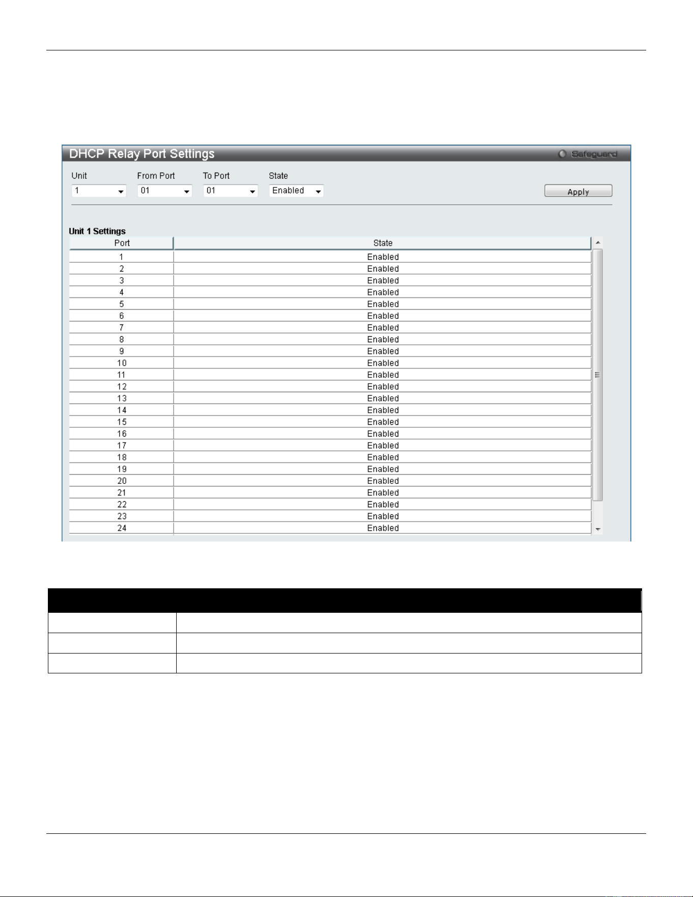
xStack® DGS-3420 Series Layer 2 Managed Stackable Gigabit Switch Web UI Reference Guide
367
DHCP Relay Port Settings
This window is used to configure the state of the DHCP relay function for each port.
To view this window, click Network Application > DHCP > DHCP Relay > DHCP Relay Port Settings as shown
below:
Figure 9-8 DHCP Relay Port Settings window
The fields that can be configured are described below:
Parameter Description
Unit
Select the unit you wish to configure.
From Port / To Port
Select the range of port, used for this configuration, here.
State
Select to enable or disable the DHCP relay port settings state.
Click the Apply button to accept the changes made.
DHCP Server
DHCP, or Dynamic Host Configuration Protocol, allows the switch to delegate IP addresses, subnet masks, default
gateways and other IP parameters to devices that request this information. This occurs when a DHCP enabled device
is booted on or attached to the locally attached network. This device is known as the DHCP client and when enabled, it
will emit query messages on the network before any IP parameters are set. When the DHCP server receives this
request, it returns a response to the client, containing the previously mentioned IP information that the DHCP client
then utilizes and sets on its local configurations.
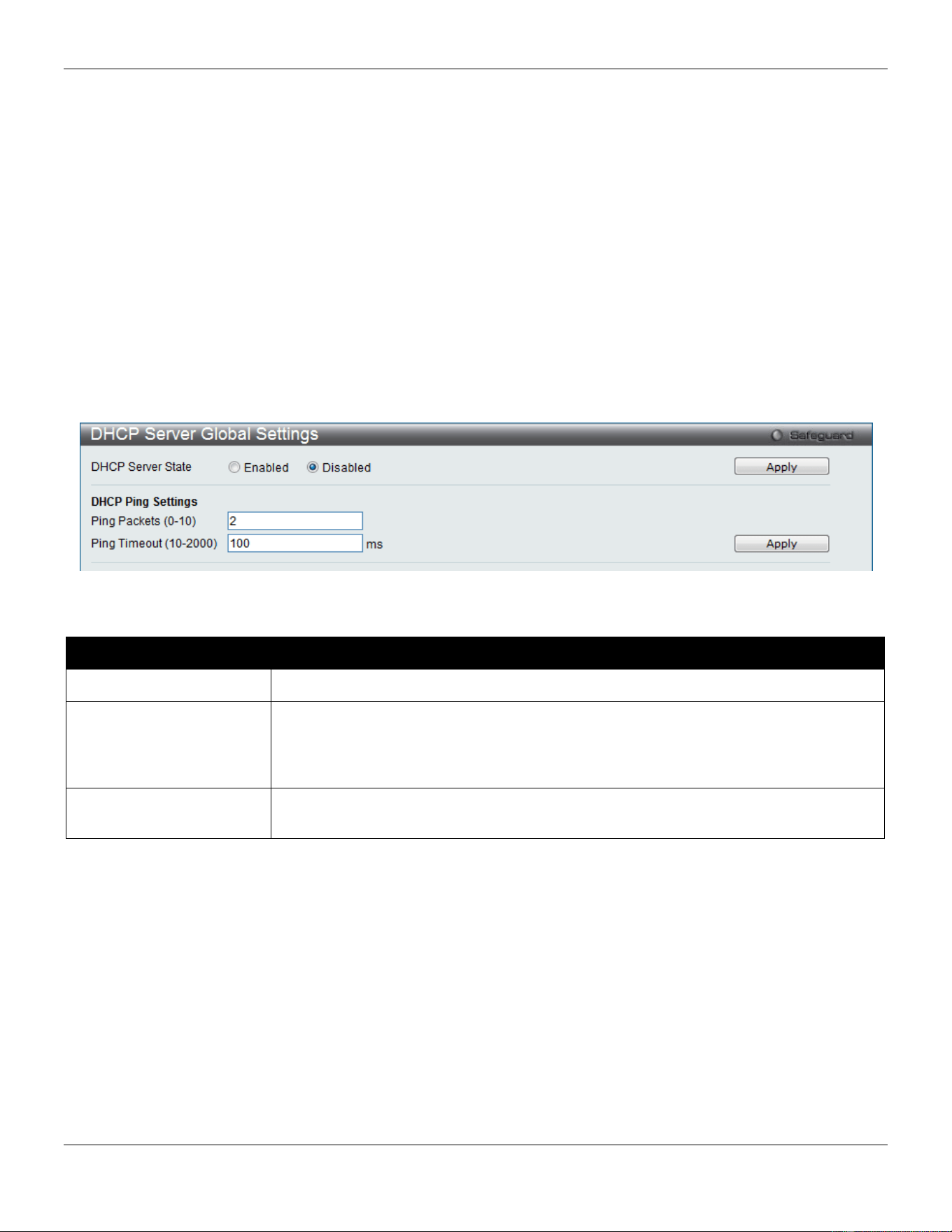
xStack® DGS-3420 Series Layer 2 Managed Stackable Gigabit Switch Web UI Reference Guide
368
The user can configure many DHCP related parameters that it will utilize on its locally attached network, to control and
limit the IP settings of clients desiring an automatic IP configuration, such as the lease time of the allotted IP address,
the range of IP addresses that will be allowed in its DHCP pool, the ability to exclude various IP addresses within the
pool so as not to make identical entries on its network, or to assign the IP address of an important device (such as a
DNS server or the IP address of the default route) to another device on the network.
Users also have the ability to bind IP addresses within the DHCP pool to specific MAC addresses in order to keep
consistent the IP addresses of devices that may be important to the upkeep of the network that require a static IP
address.
DHCP Server Global Settings
This window is used to configure the DHCP server global parameters.
To view this window, click Network Application > DHCP > DHCP Server > DHCP Server Global Settings as shown
below:
Figure 9-9 DHCP Server Global Settings Window
The fields that can be configured are described below:
Parameter Description
DHCP Server State
Click the radio buttons to enable or disable the DHCP Server State.
Ping Packets (0-10)
Enter the numbers of ping packet that the Switch will send out on the network
containing the IP address to be allotted. If the ping request is not returned, the IP
address is considered unique to the local network and then allotted to the requesting
client. 0 means there is no ping test. The default value is 2.
Ping Timeout (10-2000)
Enter the amount of time the DHCP server must waits before timing out a ping packet.
The default value is 100.
Click the Apply button to accept the changes made for each individual section.
DHCP Server Exclude Address Settings
The DHCP server assumes that all IP addresses in a DHCP pool subnet are available for assigning to DHCP clients.
You must use this page to specify the IP address that the DHCP server should not assign to clients. This command
can be used multiple times in order to define multiple groups of excluded addresses.
To view this window, click Network Application > DHCP > DHCP Server > DHCP Server Exclude Address Settings
as shown below:
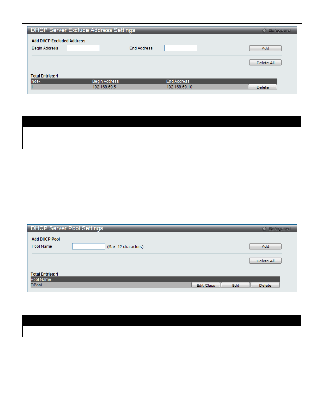
xStack® DGS-3420 Series Layer 2 Managed Stackable Gigabit Switch Web UI Reference Guide
369
Figure 9-10 DHCP Server Exclude Address Settings Window
The fields that can be configured are described below:
Parameter Description
Begin Address
Enter the starting IP Address.
End Address
Enter the ending IP Address.
Click the Add button to add a new entry based on the information entered.
Click the Delete All button to remove all the entries listed.
Click the Delete button to remove the specific entry.
DHCP Server Pool Settings
This window is used to add and delete the DHCP server pool.
To view this window, click Network Application > DHCP > DHCP Server > DHCP Server Pool Settings as shown
below:
Figure 9-11 DHCP Server Pool Settings Window
The fields that can be configured are described below:
Parameter Description
Pool Name
Enter the DHCP Server Pool name.
Click the Add button to add a new entry based on the information entered.
Click the Delete All button to remove all the entries listed.
Click the Edit button to re-configure the specific entry.
Click the Delete button to remove the specific entry.
After clicking the Edit button, the following page will appear:
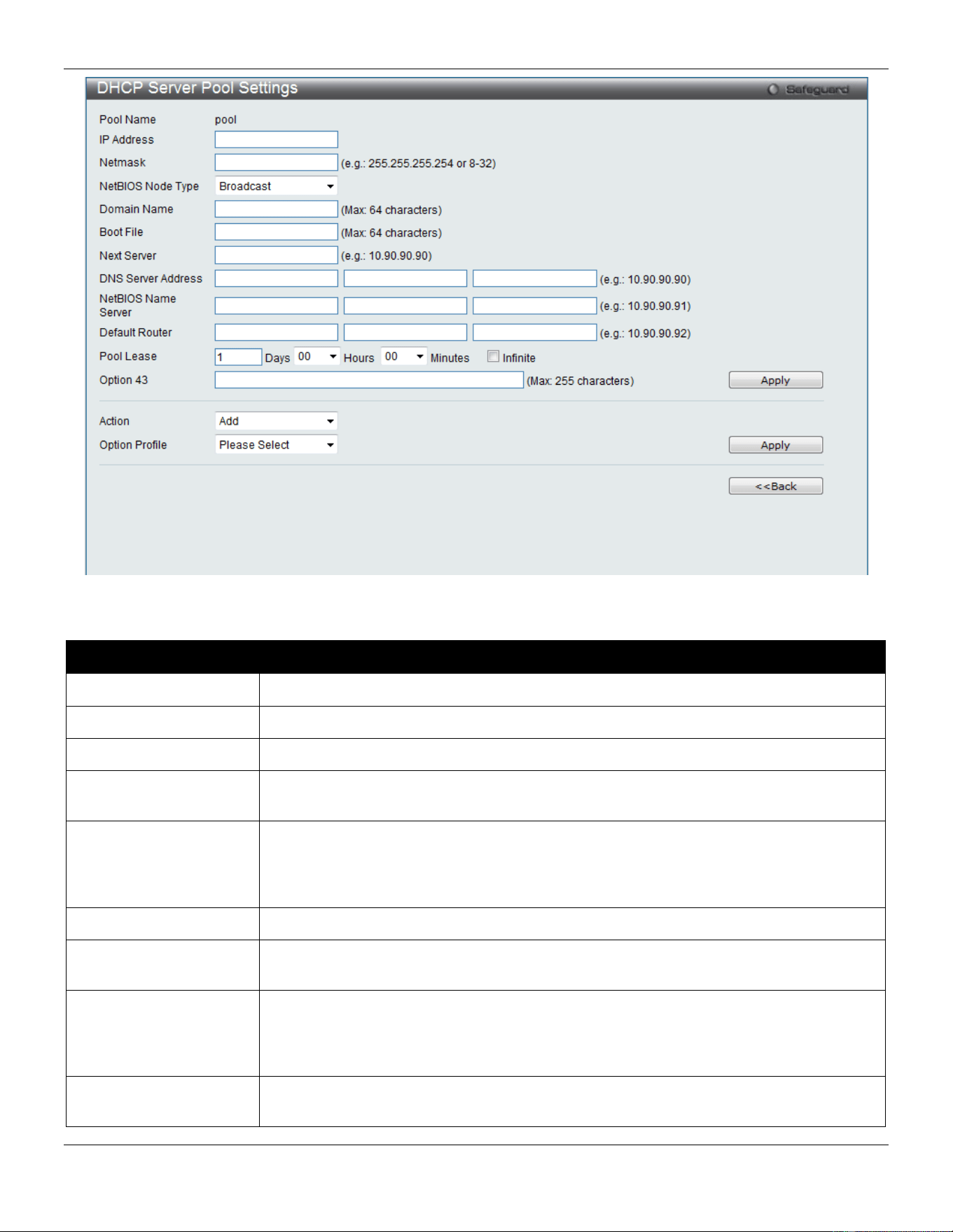
xStack® DGS-3420 Series Layer 2 Managed Stackable Gigabit Switch Web UI Reference Guide
370
Figure 9-12 DHCP Server Pool Settings (Edit) Window
The fields that can be configured are described below:
Parameter Description
IP Address
Enter the network address of the pool.
Netmask
Enter the Netmask for the network address.
NetBIOS Node Type
NetBIOS node type for a Microsoft DHCP client.
Domain Name
Domain name of client. The domain name configured here will be used as the default
domain name by the client.
Boot File
File name of boot image. The boot file is used to store the boot image for the client. The
boot image is generally the operating system the client uses to load. If this option is
input twice for the same pool, the second command will overwrite the first command. If
the boot file is not specified, the boot file information will not be provided to the client.
Next Server
Enter the next server IP address.
DNS Server Address
IP address of DNS server. Specifies the IP address of a DNS server that is available to
a DHCP client. Up to three IP addresses can be specified in one command line.
NetBIOS Name Server
IP address of WINS server. Windows Internet Naming Service (WINS) is a name
resolution service that Microsoft DHCP clients use to correlate host names to IP
addresses within a general grouping of networks. Up to three IP addresses can be
specified in one command line.
Default Router
IP address of default router. Specifies the IP address of the default router for a DHCP
client. Up to three IP addresses can be specified in one command line.
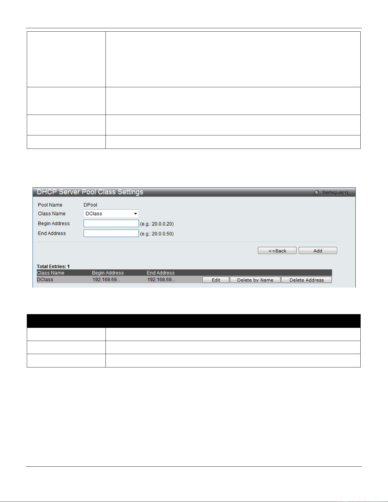
xStack® DGS-3420 Series Layer 2 Managed Stackable Gigabit Switch Web UI Reference Guide
371
Pool Lease
By default, each IP address assigned by a DHCP server comes with a one-day lease,
which is the amount of time that the address is valid. Tick the Infinite check box to have
infinite lease.
Days – Days of lease.
Hours – Hours of lease.
Minutes – Minutes of lease
Option 43
This option is used to add or delete DHCP Option 43. The DHCP server may contain
this option in the DHCP reply according to Option 55 in the client’s request packet. Enter
the DHCP Option 43 string used here.
Action Select the Option profile action that will be taken. Options to choose from are Add and
Delete.
Option Profile
Select the Option profile that will be associated with this DHCP server pool.
Click the Apply button to accept the changes made.
Click the <<Back button to discard the changes made and return to the previous page.
After clicking the Edit Class button, the following page will appear:
Figure 9-13 DHCP Server Pool Settings (Edit Class) Window
The fields that can be configured are described below:
Parameter Description
Class Name
Enter the DHCP class’s name used here. This name can be up to 12 characters long.
Begin Address
Enter the beginning IP address used for the DHCP pool here.
End Address
Enter the ending IP address used for the DHCP pool here.
Click the Add button to add a new entry based on the information entered.
Click the <<Back button to discard the changes made and return to the previous page.
Click the Edit button to re-configure the specific entry.
Click the Delete By Name button to remove the specific entry based on the name.
Click the Delete By Address button to remove the specific entry based on the address.
DHCP Server Class Settings
On this page, the user can configure the DHCP server class settings.
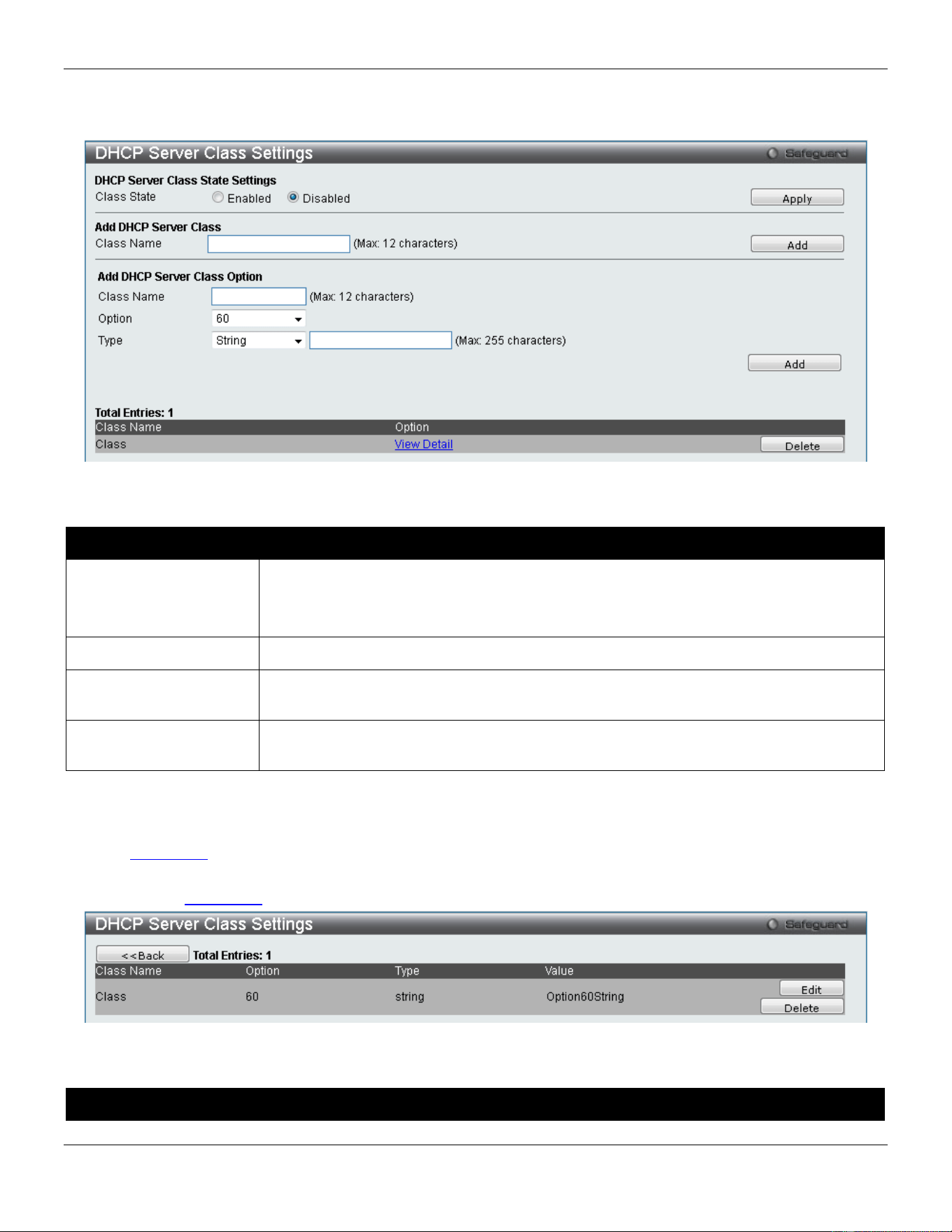
xStack® DGS-3420 Series Layer 2 Managed Stackable Gigabit Switch Web UI Reference Guide
372
To view this window, click Network Application > DHCP > DHCP Server > DHCP Server Class Settings as shown
below:
Figure 9-14 DHCP Server Class Settings window
The fields that can be configured are described below:
Parameter Description
Class State
Specifies the DHCP Server Class’ state here.
Enable - Specifies that the DHCP Server Class feature will be enabled.
Disable - Specifies that the DHCP Server Class feature will be enabled.
Class Name
Enter the DHCP class name used here. This name can be up to 12 characters long.
Option
Enter the Option type that will be associated with this DHCP server class. Options to
choose from are 60 and 82.
Type
Select and enter the type variable linked to this class here. Options to choose from, prior
to the textbox, are String and Hex.
Click the Apply button to accept the changes made.
Click the Add button to add a new entry based on the information entered.
Click the Delete button to remove the specific entry.
Click the View Detail link to view more details regarding the specific entry.
After clicking the View Detail link, the following window will appear:
Figure 9-15 DHCP Server Class Settings window (View Details)
The fields that can be configured are described below:
Parameter Description
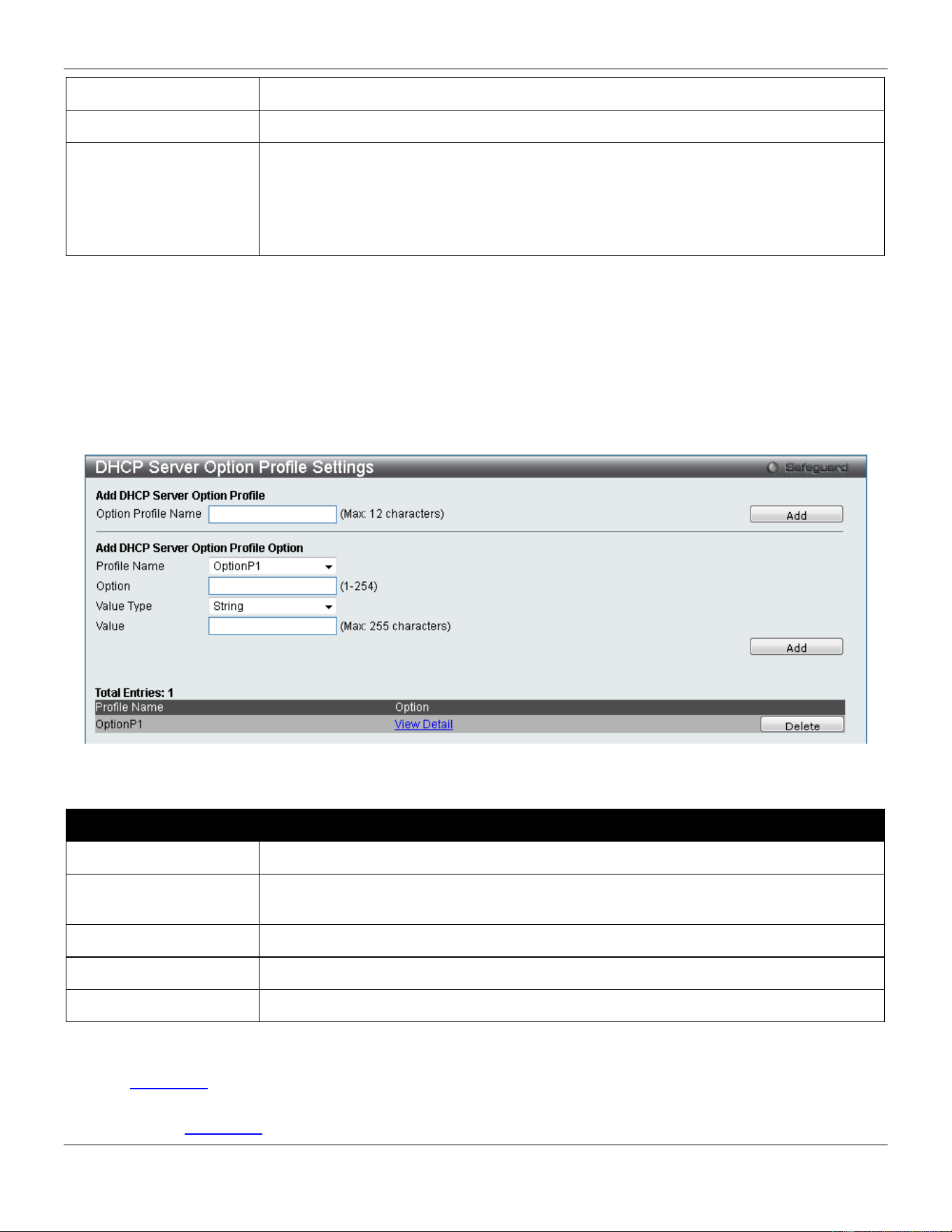
xStack® DGS-3420 Series Layer 2 Managed Stackable Gigabit Switch Web UI Reference Guide
373
Class Name
Displays the DHCP class name used here.
Option Specifies the Option index that will be added. Options to choose from are 60 and 82.
Type
Specifies the DHCP class string or HEX type used.
String - Enter the character string used here. This string can be up to 255 characters
long.
Hex - Enter the hexadecimal value of the string used here. This value can be up to 255
characters long.
Click the Edit button to re-configure the specific entry.
Click the Delete button to remove the specific entry.
DHCP Server Option Profile Settings
Here user can create and configure custom DHCP server option profiles.
To view this window, click Network Application > DHCP > DHCP Server > DHCP Server Option Profile Settings as
shown below:
Figure 9-16 DHCP Server Option Profile Settings window
The fields that can be configured are described below:
Parameter Description
Option Profile Name
Enter the new DHCP server Option profile name used here.
Profile Name
After creating a new DHCP server Option profile (above), the available profiles will be
listed here for selection.
Option
Enter the custom DHCP server Option value used here.
Value Type Select the value type used here. Options to choose from are String and Hex.
Value
Enter the option value here.
Click the Add button to add a new entry based on the information entered.
Click the Delete button to remove the specific entry.
Click the View Detail link to view more details regarding the specific entry.
After clicking the View Detail link, the following window will appear:
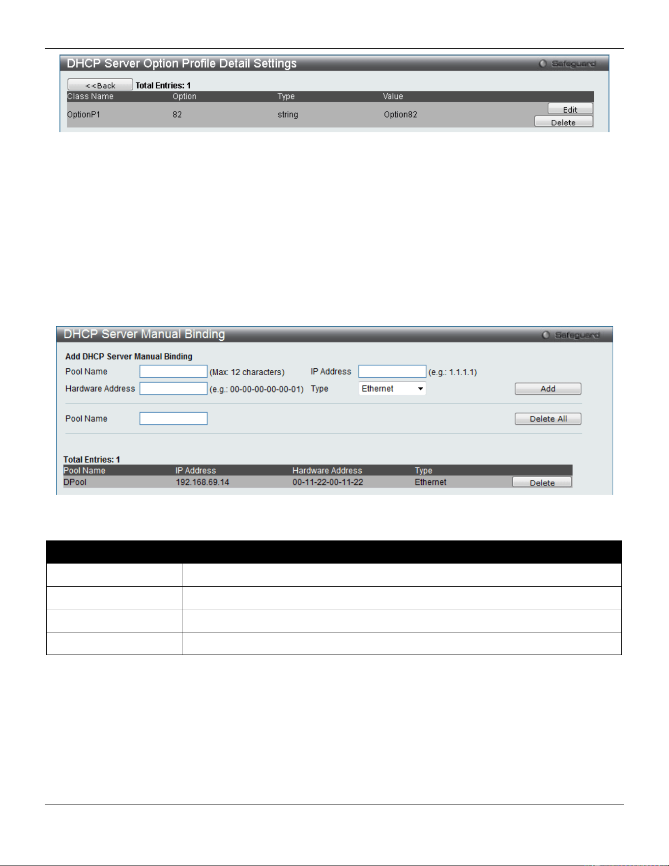
xStack® DGS-3420 Series Layer 2 Managed Stackable Gigabit Switch Web UI Reference Guide
374
Figure 9-17 DHCP Server Option Profile Settings window (View Details)
Click the Edit button to re-configure the specific entry.
Click the Delete button to remove the specific entry.
DHCP Server Manual Binding
An address binding is a mapping between the IP address and MAC address of a client. The IP address of a client can
be assigned manually by an administrator or assigned automatically from a pool by a DHCP server. The dynamic
binding entry will be created when an IP address is assigned to the client from the pool network’s address.
To view this window, click Network Application > DHCP > DHCP Server > DHCP Server Manual Binding as shown
below:
Figure 9-18 DHCP Server Manual Binding Window
The fields that can be configured are described below:
Parameter Description
Pool Name
Enter the DHCP Server Pool name.
IP Address
IP address which will be assigned to specified client.
Hardware Address
Enter the hardware address.
Type
Either Ethernet or IEEE802 can be specified.
Click the Add button to add a new entry based on the information entered.
Click the Delete All button to remove all the entries listed.
Click the Delete button to remove the specific entry.
DHCP Server Dynamic Binding
This window is used to delete the DHCP server dynamic binding table.
To view this window, click Network Application > DHCP > DHCP Server > DHCP Server Dynamic Binding as
shown below:
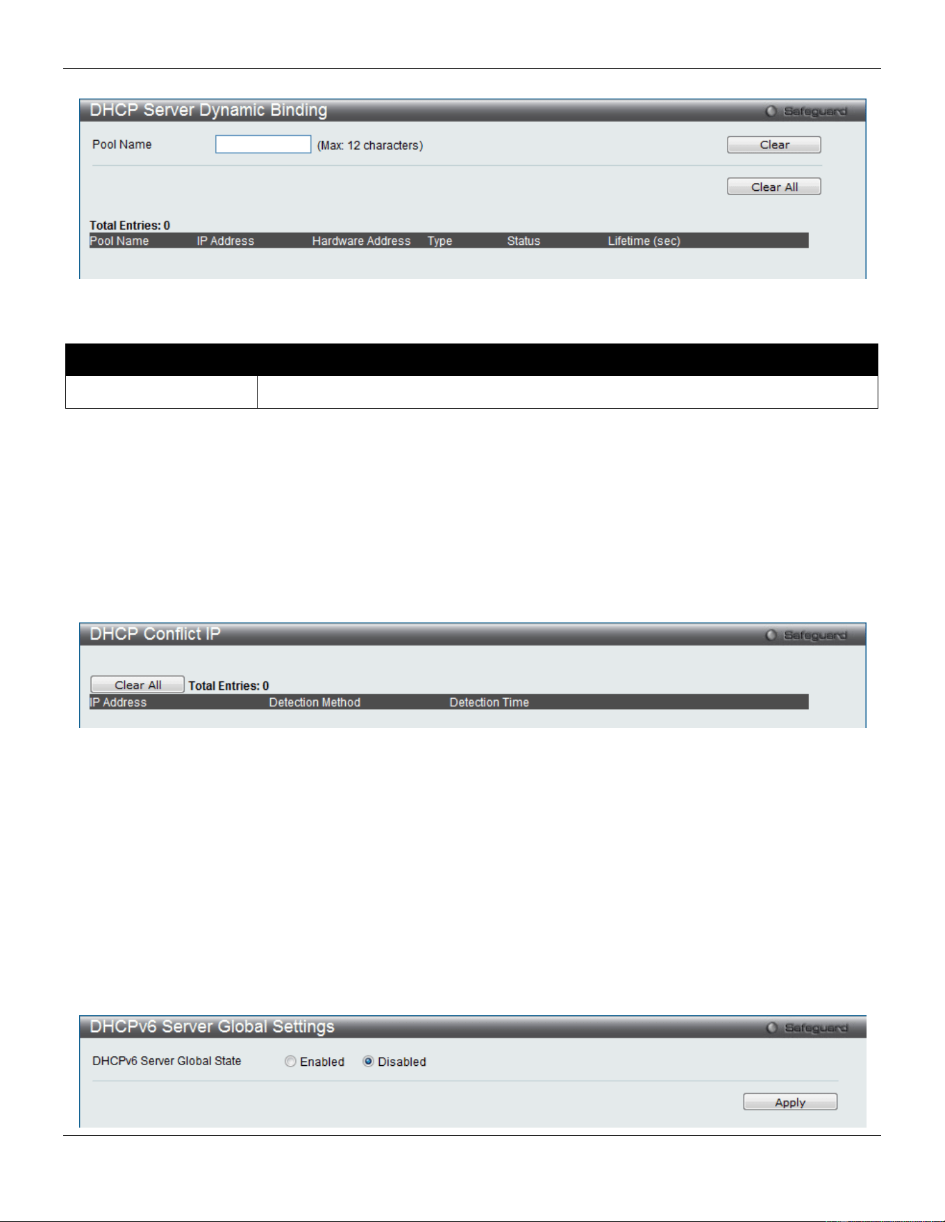
xStack® DGS-3420 Series Layer 2 Managed Stackable Gigabit Switch Web UI Reference Guide
375
Figure 9-19 DHCP Server Dynamic Binding Window
The fields that can be configured are described below:
Parameter Description
Pool Name
Enter the DHCP Server Pool name.
Click the Clear button to clear all the information entered in the fields.
Click the Clear All button to remove all the entries listed in the table.
DHCP Conflict IP
The DHCP server will use PING packet to determine whether an IP address is conflict with other host before binding
this IP. The IP address which has been identified conflict will be moved to the conflict IP database. The system will not
attempt to bind the IP address in the conflict IP database unless the user clears it from the conflict IP database.
To view this window, click Network Application > DHCP > DHCP Server > DHCP Conflict IP as shown below:
Figure 9-20 DHCP Conflict IP Window
Click the Clear All button to remove all the entries listed in the table.
DHCPv6 Server
DHCPv6 Server Global Settings
This command is used to enable the DHCPv6 server function on the Switch
To view this window, click Network Application > DHCP > DHCPv6 Server > DHCPv6 Server Global Settings as
shown below:
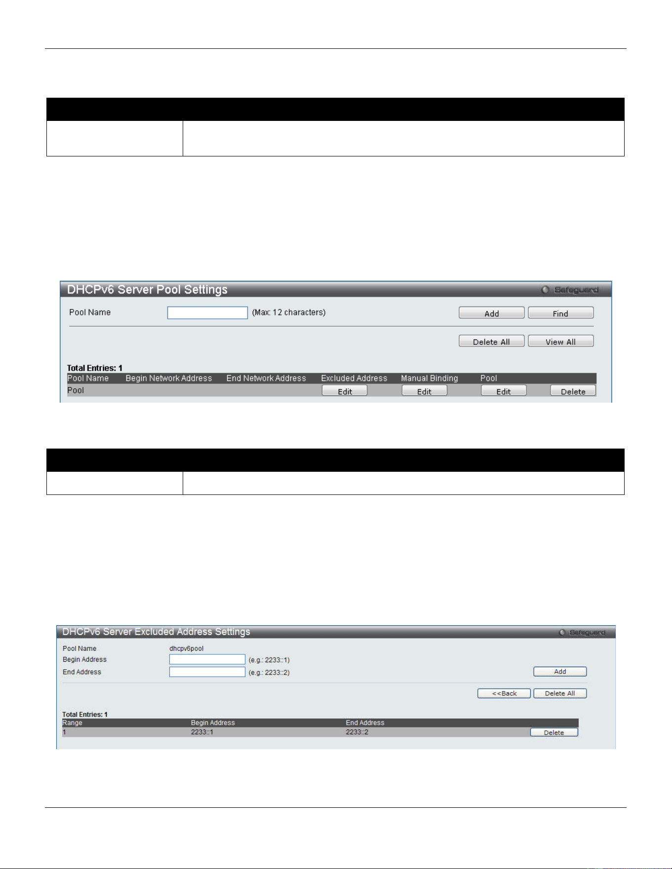
xStack® DGS-3420 Series Layer 2 Managed Stackable Gigabit Switch Web UI Reference Guide
376
Figure 9-21 DHCPv6 Server Global Settings window
The fields that can be configured are described below:
Parameter Description
DHCPv6 Server Global
State
Click the radio buttons to enable or disable the DHCPv6 Server State.
Click the Apply button to accept the changes made.
DHCPv6 Server Pool Settings
This window is used to create and configure a DHCPv6 pool.
To view this window, click Network Application > DHCP > DHCPv6 Server > DHCPv6 Server Pool Settings as
shown below:
Figure 9-22 DHCPv6 Server Pool Settings window
The fields that can be configured are described below:
Parameter Description
Pool Name
Enter the DHCPv6 Server Pool name.
Click the Add button to add a new entry based on the information entered.
Click the Find button to locate a specific entry based on the information entered.
Click the Delete All button to remove all the entries listed.
Click the View All button to display all the existing entries.
Click the Edit button under various columns to re-configure the specific entry.
Click the Delete button to remove the specific entry.
Click the Edit button under Excluded Address to see the following window.
Figure 9-23 DHCPv6 Server Excluded Address Settings window
The fields that can be configured are described below:
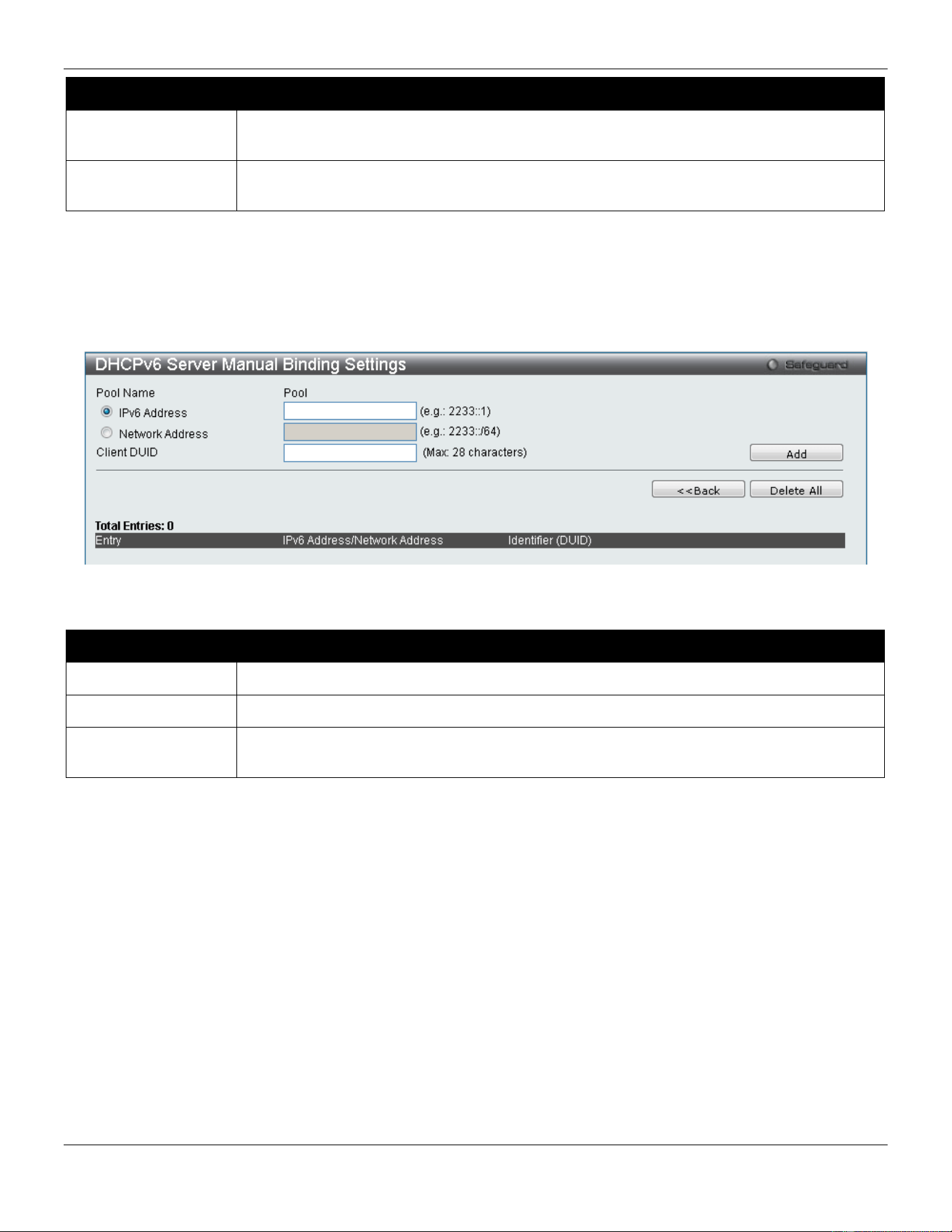
xStack® DGS-3420 Series Layer 2 Managed Stackable Gigabit Switch Web UI Reference Guide
377
Parameter Description
Begin Address
Enter the beginning IPv6 address of the range of IPv6 addresses to be excluded from the
DHCPv6 pool.
End Address
Enter the ending IPv6 address of the range of IPv6 addresses to be excluded from the
DHCPv6 pool.
Click the Add button to add a new entry based on the information entered.
Click the <<Back button to return to the previous window.
Click the Delete All button to remove all the entries listed.
Click the Delete button to remove the specific entry.
Click the Edit button under Manual Binding to see the following window.
Figure 9-24 DHCPv6 Server Manual Binding Settings window
The fields that can be configured are described below:
Parameter Description
IPv6 Address
Enter the IPv6 address to be statically bound to a device.
Network Address
Enter the IPv6 networks address that will be statically bound to a device here.
Client DUID
Enter the DUID of the device to be statically bound to the IPv6 address entered in the
previous field.
Click the Add button to add a new entry based on the information entered.
Click the <<Back button to return to the previous window.
Click the Delete All button to remove all the entries listed.
Click the Delete button to remove the specific entry.
Click the Edit button under Pool to see the following window.
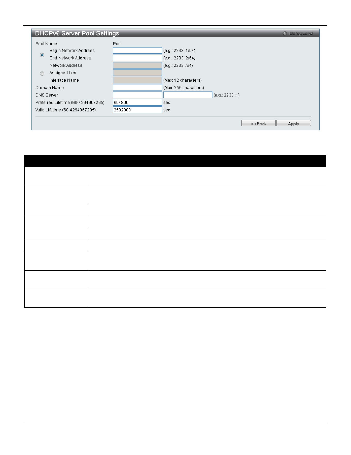
xStack® DGS-3420 Series Layer 2 Managed Stackable Gigabit Switch Web UI Reference Guide
378
Figure 9-25 DHCPv6 Server Pool Settings window
The fields that can be configured are described below:
Parameter Description
Begin Network
Address
Enter the beginning IPv6 network address of the DHCPv6 pool.
End Network
Address
Enter the ending IPv6 network address of the DHCPv6 pool.
Network Address
Enter the IPv6 network address of the DHCPv6 pool.
Assigned Len
Enter the assigned length value here.
Interface Name
Enter the interface name used here.
Domain Name
The domain name is used by client when resolving hostnames with DNS.
DNS Server
Enter the DNS server IPv6 address for this pool. Users may specify up to two DNS server
addresses.
Preferred Lifetime
(60-4294967295)
The amount of time (in seconds) that the IPv6 address, based on the specified pool,
remains in preferred state.
Valid Lifetime (60-
4294967295)
The amount of time (in seconds) that the IPv6 address, based on the specified pool,
remains in valid state.
Click the <<Back button to return to the previous window.
Click the Apply button to accept the changes made.
DHCPv6 Server Dynamic Binding
This window is used to show the DHCPv6 dynamic binding information.
To view this window, click Network Application > DHCP > DHCPv6 Server > DHCPv6 Server Dynamic Binding as
shown below:
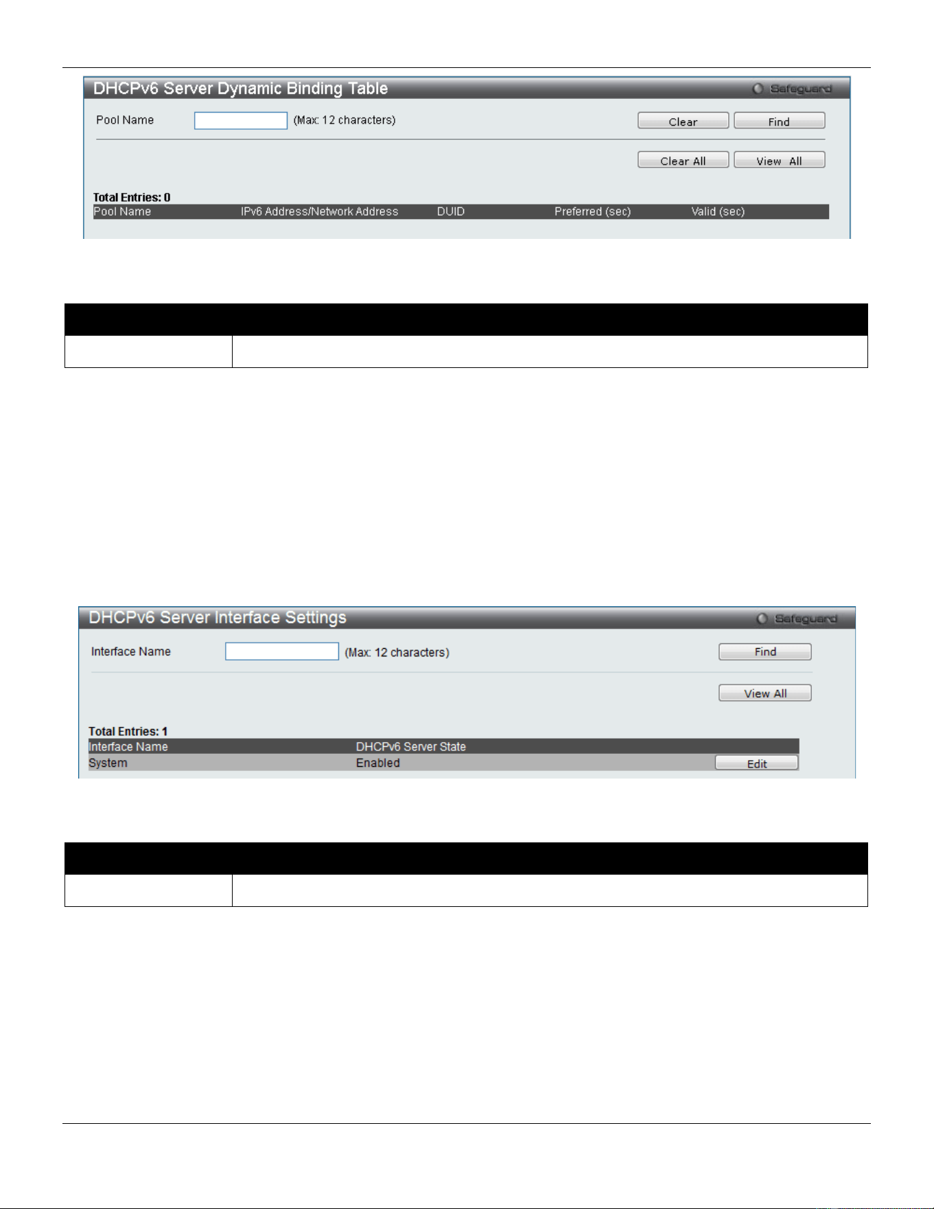
xStack® DGS-3420 Series Layer 2 Managed Stackable Gigabit Switch Web UI Reference Guide
379
Figure 9-26 DHCPv6 Server Dynamic Binding Table window
The fields that can be configured are described below:
Parameter Description
Pool Name
Enter the name of the DHCPv6 pool for which to view dynamic binding information.
Click the Clear button to clear all the information entered in the fields.
Click the Find button to locate a specific entry based on the information entered.
Click the Clear All button to remove all the entries listed in the table.
Click the View All button to display all the existing entries.
DHCPv6 Server Interface Settings
This window is used to display and configure the DHCPv6 Server state per interface
To view this window, click Network Application > DHCP > DHCPv6 Server > DHCPv6 Server Interface Settings as
shown below:
Figure 9-27 DHCPv6 Server Interface Settings window
The fields that can be configured are described below:
Parameter Description
Interface Name
Enter the name of the IP interface.
Click the Find button to locate a specific entry based on the information entered.
Click the View All button to display all the existing entries.
Click the Edit button to re-configure the specific entry.
DHCPv6 Relay
DHCPv6 Relay Global Settings
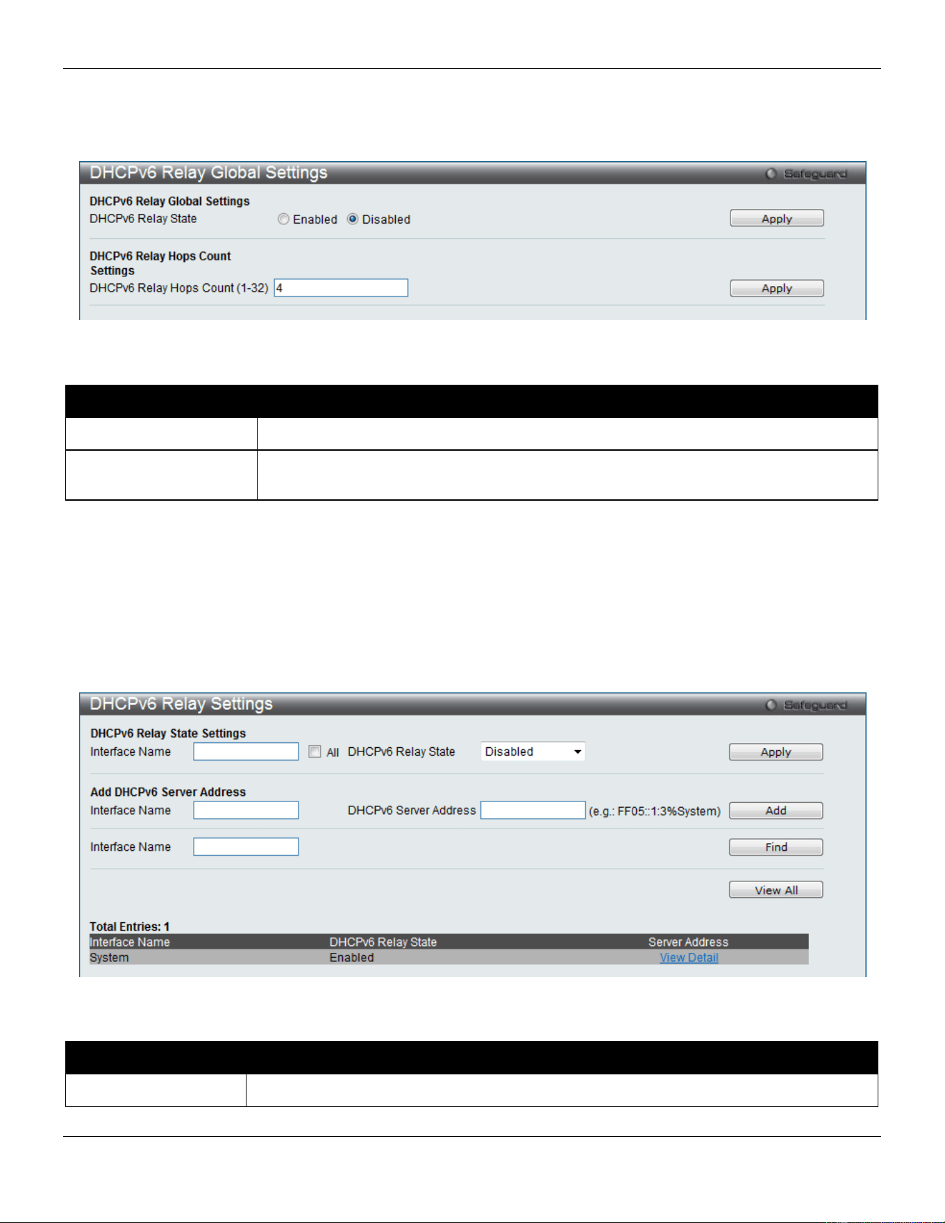
xStack® DGS-3420 Series Layer 2 Managed Stackable Gigabit Switch Web UI Reference Guide
380
This window is used to configure the DHCPv6 relay function on the Switch.
To view this window, click Network Application > DHCP > DHCPv6 Relay > DHCPv6 Relay Global Settings as
shown below:
Figure 9-28 DHCPv6 Relay Global Settings window
The fields that can be configured are described below:
Parameter Description
DHCPv6 Relay State
Click the radio buttons to enable or disable the DHCPv6 relay function.
DHCPv6 Relay Hops
Count (1-32)
Enter the number of relay agents that have to be relayed in this message. The default
value is 4.
Click the Apply button to accept the changes made for each individual section.
DHCPv6 Relay Settings
This window is used to configure the DHCPv6 relay state of one or all of the specified interfaces, and add or display a
destination IPv6 address to or from the switch’s DHCPv6 relay table.
To view this window, click Network Application > DHCP > DHCPv6 Relay > DHCPv6 Relay Settings as shown
below:
Figure 9-29 DHCPv6 Relay Settings window
The fields that can be configured are described below:
Parameter Description
Interface Name Enter the name of the IPv6 interface. Tick the All check box to select all IPv6 interfaces.
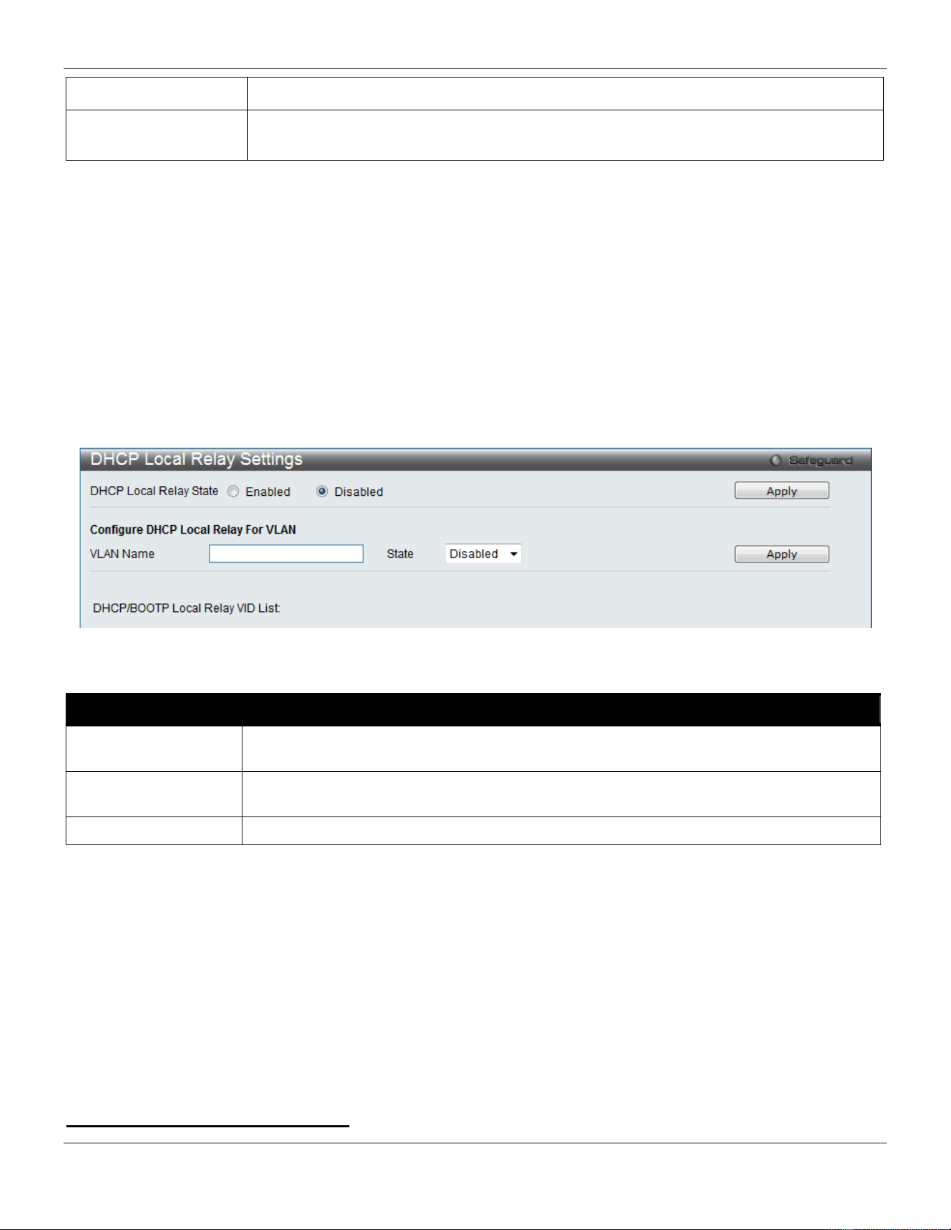
xStack® DGS-3420 Series Layer 2 Managed Stackable Gigabit Switch Web UI Reference Guide
381
DHCPv6 Relay State
Use the drop-down menu to enable or disable the DHCPv6 relay state of the interface.
DHCPv6 Server
Address
Enter the DHCPv6 server IPv6 address.
Click the Apply button to accept the changes made.
Click the Add button to add a new entry based on the information entered.
Click the Find button to locate a specific entry based on the information entered.
Click the View All button to display all the existing entries.
DHCP Local Relay Settings
The DHCP local relay settings allows the user to add option 82 into DHCP request packets when the DHCP client gets
an IP address from the same VLAN. If the DHCP local relay settings are not configured, the Switch will flood the
packets to the VLAN. In order to add option 82 into the DHCP request packets, the DHCP local relay settings and the
state of the Global VLAN need to be enabled.
To view this window, click Network Application > DHCP > DHCP Local Relay Settings as shown below:
Figure 9-30 DHCP Local Relay Settings window
The fields that can be configured are described below:
Parameter Description
DHCP Local Relay
Global State
Enable or disable the DHCP Local Relay Global State. The default is Disabled.
VLAN Name
This is the VLAN Name that identifies the VLAN the user wishes to apply the DHCP Local
Relay operation.
State
Enable or disable the configuration of the DHCP Local Relay for VLAN state.
Click the Apply button to accept the changes made for each individual section.
DNS
Computer users usually prefer to use text names for computers for which they may want to open a connection.
Computers themselves, require 32 bit IP addresses. Somewhere, a database of network devices’ text names and their
corresponding IP addresses must be maintained.
The Domain Name System (DNS) is used to map names to IP addresses throughout the Internet and has been
adapted for use within intranets. For two DNS servers to communicate across different subnets, the DNS Relay of the
Switch must be used. The DNS servers are identified by IP addresses.
Mapping Domain Names to Addresses
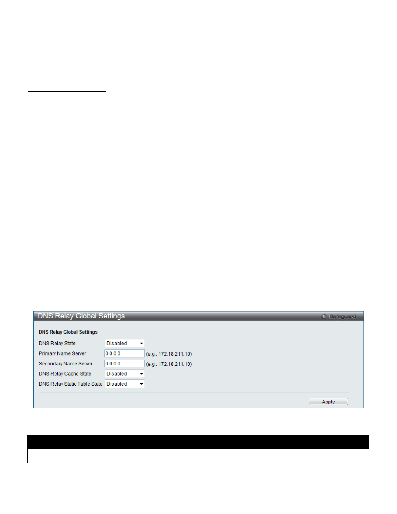
xStack® DGS-3420 Series Layer 2 Managed Stackable Gigabit Switch Web UI Reference Guide
382
Name-to-address translation is performed by a program called a Name server. The client program is called a Name
resolver. A Name resolver may need to contact several Name servers to translate a name to an address.
The Domain Name System (DNS) servers are organized in a somewhat hierarchical fashion. A single server often
holds names for a single network, which is connected to a root DNS server - usually maintained by an ISP.
Domain Name Resolution
The domain name system can be used by contacting the name servers one at a time, or by asking the domain name
system to do the complete name translation. The client makes a query containing the name, the type of answer
required, and a code specifying whether the domain name system should do the entire name translation, or simply
return the address of the next DNS server if the server receiving the query cannot resolve the name.
When a DNS server receives a query, it checks to see if the name is in its sub domain. If it is, the server translates the
name and appends the answer to the query, and sends it back to the client. If the DNS server cannot translate the
name, it determines what type of name resolution the client requested. A complete translation is called recursive
resolution and requires the server to contact other DNS servers until the name is resolved. Iterative resolution specifies
that if the DNS server cannot supply an answer, it returns the address of the next DNS server the client should contact.
Each client must be able to contact at least one DNS server, and each DNS server must be able to contact at least one
root server.
The address of the machine that supplies domain name service is often supplied by a DHCP or BOOTP server, or can
be entered manually and configured into the operating system at startup.
DNS Relay
DNS Relay Global Settings
This window is used to configure the DNS Relay global parameters.
To view this window, click Network Application > DNS > DNS Relay > DNS Relay Global Settings as shown below:
Figure 9-31 DNS Relay Global Settings Window
The fields that can be configured are described below:
Parameter Description
DNS Relay State
Use the drop-down menu to enable or disable the DNS relay state.
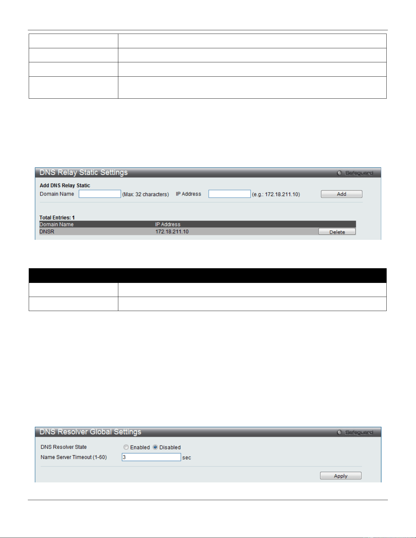
xStack® DGS-3420 Series Layer 2 Managed Stackable Gigabit Switch Web UI Reference Guide
383
Primary Name Server
Enter the primary DNS server IP address.
Secondary Name Server
Enter the secondary DNS server IP address.
DNS Relay Cache State
Use the drop-down menu to enable or disable the DNS relay cache state.
DNS Relay Static Table
State
Use the drop-down menu to enable or disable the DNS relay static table state.
Click the Apply button to accept the changes made.
DNS Relay Static Settings
This window is used to add or delete static entries into the switch’s DNS resolution table.
To view this window, click Network Application > DNS > DNS Relay > DNS Relay Static Settings as shown below:
Figure 9-32 DNS Relay Static Settings Window
The fields that can be configured are described below:
Parameter Description
Domain Name
Enter the domain name.
IP Address
Enter the DNS Relay IP Address.
Click the Add button to add a new entry based on the information entered.
Click the Delete button to remove the specific entry.
DNS Resolver
DNS Resolver Global Settings
This window is used to configure the DNS Resolver global state of the switch.
To view this window, click Network Application > DNS Resolver > DNS Resolver Global Settings as shown below:
Figure 9-33 DNS Resolver Global Settings window
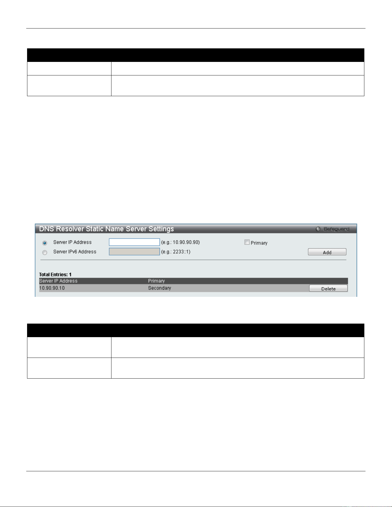
xStack® DGS-3420 Series Layer 2 Managed Stackable Gigabit Switch Web UI Reference Guide
384
The fields that can be configured are described below:
Parameter Description
DNS Resolver State
Click the radio buttons to enable or disable the DNS resolver state.
Name Server Timeout (1-
60)
The maximum time waiting for a response from a specified name server.
Click the Apply button to accept the changes made.
DNS Resolver Static Name Server Settings
The window is used to create the DNS Resolver name server of the switch. When adding a name server, if one primary
name server exists in the static name server table and a new primary name server is added, the existing primary name
server will be changed to a normal name server. If the added primary name server’s IP address is the same as an
existing normal name server’s IP address, the existing normal name server will be changed to a primary name server,
but won’t add new name server. When no primary name server is specified, the first configured name server will
automatically change to become the primary name server. If the deleted name server’s IP address is the same as one
of the existing name servers’ IP addresses, regardless of whether a normal name server or primary name server, the
name server will be deleted.
To view this window, click Network Application > DNS Resolver > DNS Resolver Static Name Server Settings as
shown below:
Figure 9-34 DNS Resolver Static Name Server Settings window
The fields that can be configured are described below:
Parameter Description
Server IP Address Enter a DNS Resolver name server’s IPv4 address here. Tick the Primary check box
to set the name server as a primary name server.
Server IPv6 Address Enter a DNS Resolver name server’s IPv6 address here. Tick the Primary check box
to set the name server as a primary name server.
Click the Add button to add a new entry based on the information entered.
Click the Delete button to remove the specific entry.
DNS Resolver Dynamic Name Server Table
This window displays the current DNS Resolver name servers.
To view this window, click Network Application > DNS Resolver > DNS Resolver Dynamic Name Server Table as
shown below:
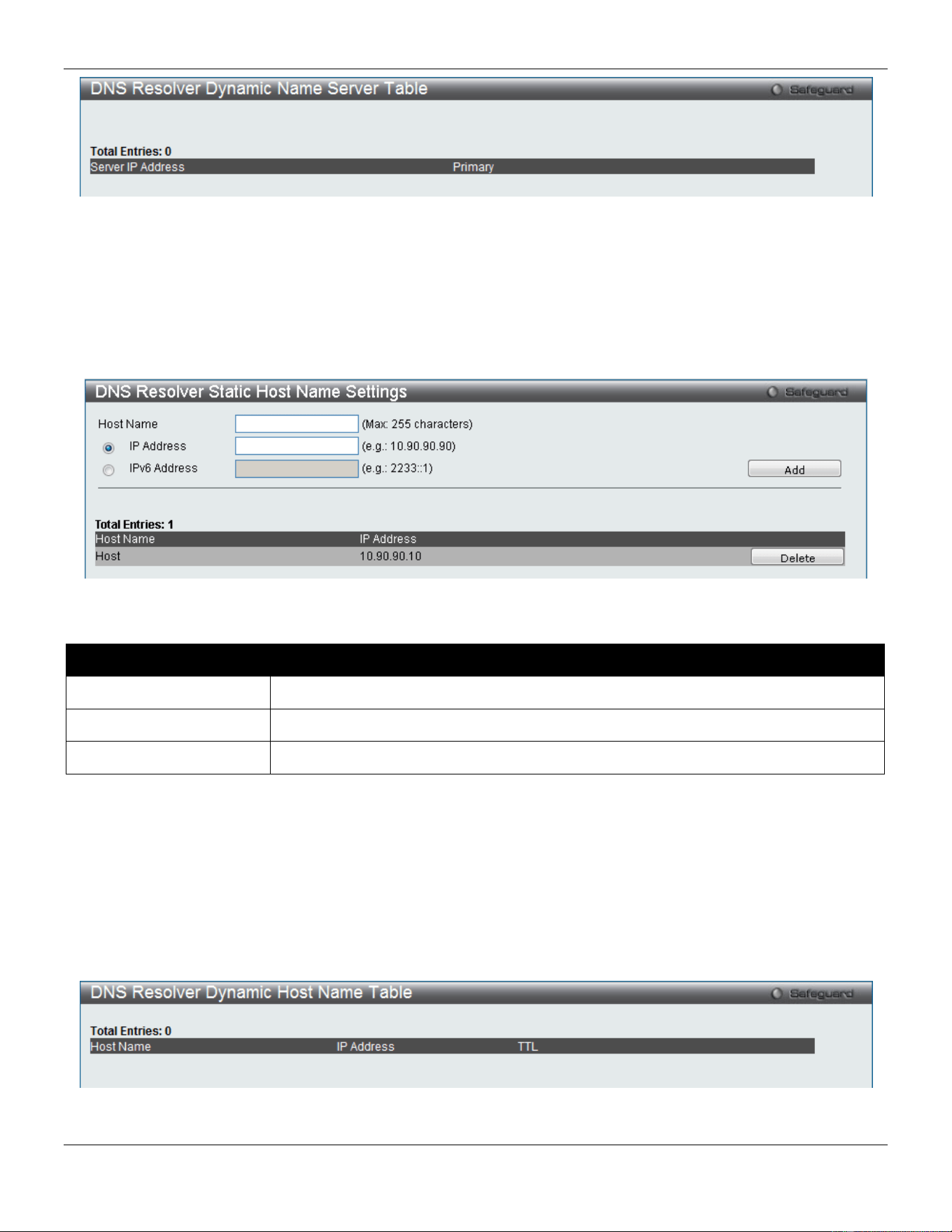
xStack® DGS-3420 Series Layer 2 Managed Stackable Gigabit Switch Web UI Reference Guide
385
Figure 9-35 DNS Resolver Dynamic Name Server Table window
DNS Resolver Static Host Name Settings
The window is used to create the static host name entry of the switch.
To view this window, click Network Application > DNS Resolver > DNS Resolver Static Host Name Settings as
shown below:
Figure 9-36 DNS Resolver Static Host Name Settings window
The fields that can be configured are described below:
Parameter Description
Host Name
Enter the name of the host.
IP Address
Enter the IPv4 address of the host here.
IPv6 Address
Enter the IPv6 address of the host here.
Click the Add button to add a new entry based on the information entered.
Click the Delete button to remove the specific entry.
DNS Resolver Dynamic Host Name Table
This window displays the current host name entries.
To view this window, click Network Application > DNS Resolver > DNS Resolver Dynamic Host Name Table as
shown below:
Figure 9-37 DNS Resolver Dynamic Host Name Table window
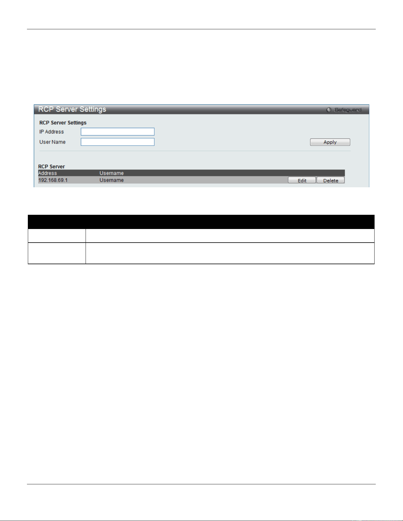
xStack® DGS-3420 Series Layer 2 Managed Stackable Gigabit Switch Web UI Reference Guide
386
RCP Server Settings
This window is used to configure global RCP server information. This global RCP Server setting can be used when the
Server or remote user name is not specified. Only ONE RCP server can be configured per system. If user does not
specify the RCP Server in the CLI command, and global RCP Server was not configured, the Switch will ask user to
input the Server IP address or remote user name while executing the RCP commands.
To view this window, click Network Application > RCP Server Settings as shown below:
Figure 9-38 RCP Server Settings Window
The fields that can be configured are described below:
Parameter Description
IP Address
The IP address of global RCP Server. By default, the server is unspecified.
User Name
The remote user name for logon into global RCP Server. By default, global server’s remote user
name is unspecified.
Click the Apply button to accept the changes made.
Click the Edit button to re-configure the specific entry.
Click the Delete button to remove the specific entry.
SMTP Settings
SMTP or Simple Mail Transfer Protocol is a function of the Switch that will send switch events to mail recipients based
on e-mail addresses entered in the window below. The Switch is to be configured as a client of SMTP while the server
is a remote device that will receive messages from the Switch, place the appropriate information into an e-mail and
deliver it to recipients configured on the Switch. This can benefit the Switch administrator by simplifying the
management of small workgroups or wiring closets, increasing the speed of handling emergency Switch events, and
enhancing security by recording questionable events occurring on the Switch.
Users can set up the SMTP server for the Switch, along with setting e-mail addresses to which switch log files can be
sent when a problem arises on the Switch.
The Switch will send out e-mail to recipients when one or more of the following events occur:
• When a cold start occurs on the Switch.
• When a port enters a link down status.
• When a port enters a link up status.
• When SNMP authentication has been denied by the Switch.
• When a switch configuration entry has been saved to the NVRAM by the Switch.

xStack® DGS-3420 Series Layer 2 Managed Stackable Gigabit Switch Web UI Reference Guide
387
• When an abnormality occurs on TFTP during a firmware download event. This includes in-process, invalid-
file, violation, file-not-found, complete and time-out messages from the TFTP server.
• When a system reset occurs on the Switch.
Information within the e-mail from the SMTP server regarding switch events includes:
• The source device name and IP address.
• A timestamp denoting the identity of the SMTP server and the client that sent the message, as well as the
time and date of the message received from the Switch. Messages that have been relayed will have
timestamps for each relay.
• The event that occurred on the Switch, prompting the e-mail message to be sent.
• When an event is processed by a user, such as save or firmware upgrade, the IP address, MAC address
and User Name of the user completing the task will be sent along with the system message of the event
occurred.
• When the same event occurs more than once, the second mail message and every repeating mail message
following will have the system’s error message placed in the subject line of the mail message.
The following details events occurring during the Delivery Process.
• Urgent mail will have high priority and be immediately dispatched to recipients while normal mail will be
placed in a queue for future transmission.
• The maximum number of un-transmitted mail messages placed in the queue cannot exceed 30 messages.
Any new messages will be discarded if the queue is full.
• If the initial message sent to a mail recipient is not delivered, it will be placed in the waiting queue until its
place in the queue has been reached, and then another attempt to transmit the message is made.• The
maximum attempts for delivering mail to recipients is three. Mail message delivery attempts will be tried
every five minutes until the maximum number of attempts is reached. Once reached and the message has
not been successfully delivered, the message will be dropped and not received by the mail recipient.
• If the Switch shuts down or reboots, mail messages in the waiting queue will be lost.
To view this window, click Network Application > SMTP Settings as shown below:
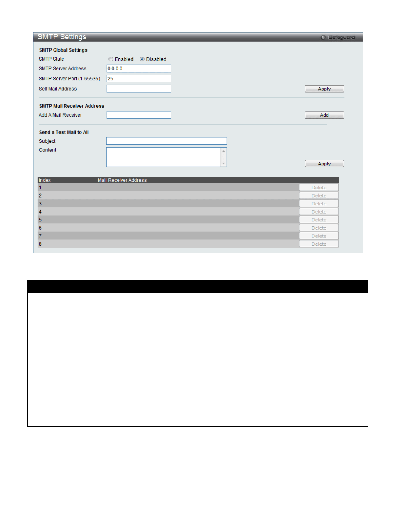
xStack® DGS-3420 Series Layer 2 Managed Stackable Gigabit Switch Web UI Reference Guide
388
Figure 9-39 SMTP Settings window
The fields that can be configured are described below:
Parameter Description
SMTP State
Use the radio button to enable or disable the SMTP service on this device.
SMTP Server
Address
Enter the IP address of the SMTP server on a remote device. This will be the device that sends
out the mail for you.
SMTP Server
Port
Enter the virtual port number that the Switch will connect with on the SMTP server. The common
port number for SMTP is 25, yet a value between 1 and 65535 can be chosen.
Self Mail
Address
Enter the e-mail address from which mail messages will be sent. This address will be the “from”
address on the e-mail message sent to a recipient. Only one self-mail address can be
configured for this Switch. This string can be no more that 64 alphanumeric characters.
Add a Mail
Receiver
Enter an e-mail address and click the Add button. Up to eight e-mail addresses can be added
per Switch. To delete these addresses from the Switch, click the corresponding Delete button in
the SMTP Mail Receiver Address table at the bottom of the window.
Send a Test
Mail to All
Here the user can send a test mail to all the addresses listed.
Click the Apply button to accept the changes made for each individual section.
Click the Add button to add a new entry based on the information entered.
Click the Delete button to remove the specific entry.
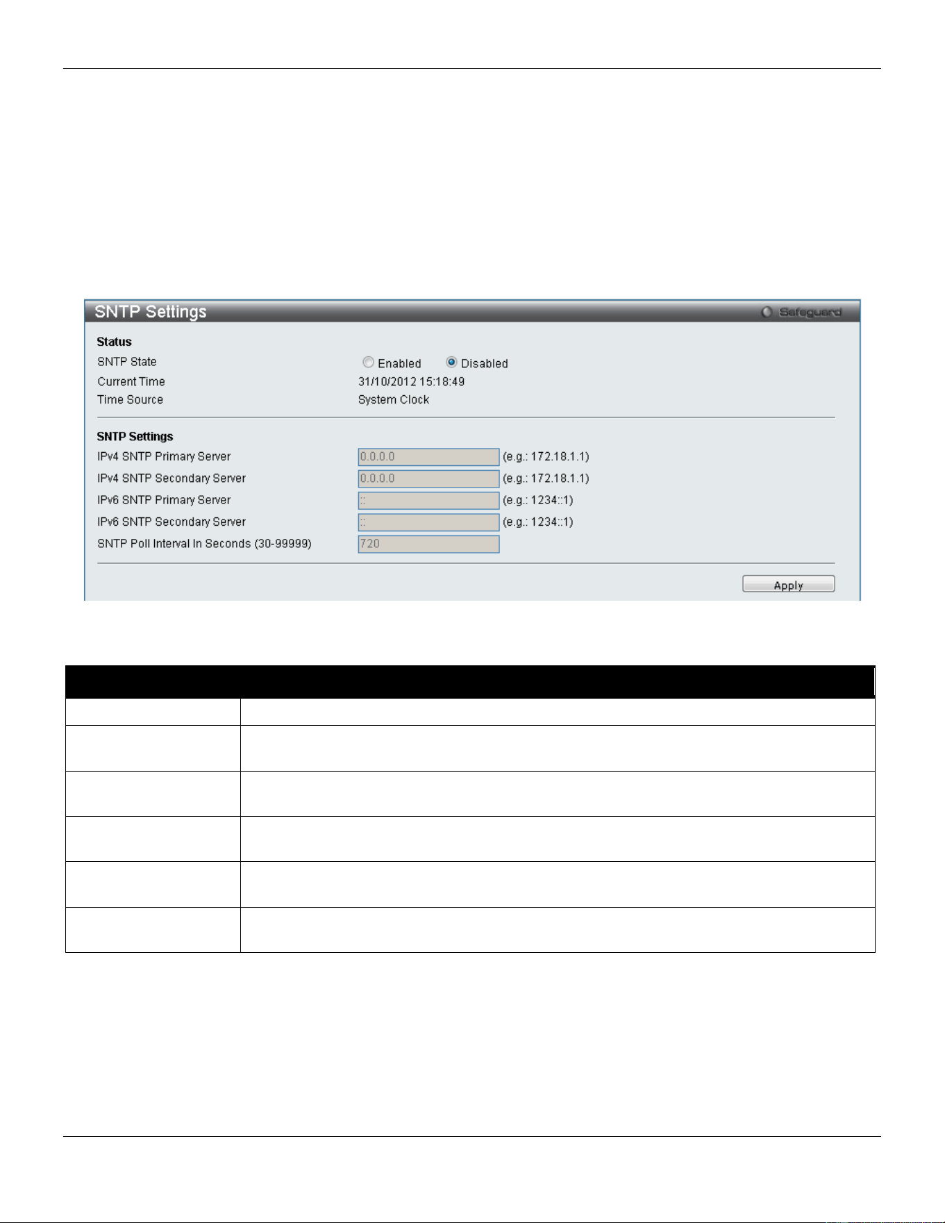
xStack® DGS-3420 Series Layer 2 Managed Stackable Gigabit Switch Web UI Reference Guide
389
SNTP
The Simple Network Time Protocol (SNTP) is a protocol for synchronizing computer clocks through the Internet. It
provides comprehensive mechanisms to access national time and frequency dissemination services, organize the
SNTP subnet of servers and clients, and adjust the system clock in each participant.
SNTP Settings
Users can configure the time settings for the Switch.
To view this window, click Network Application > SNTP > SNTP Settings as shown below:
Figure 9-40 SNTP Settings window
The fields that can be configured are described below:
Parameter Description
SNTP State
Use this radio button to enable or disable SNTP.
IPv4 SNTP Primary
Server
The IPv4 address of the primary server from which the SNTP information will be taken.
IPv4 SNTP
Secondary Server
The IPv4 address of the secondary server from which the SNTP information will be taken.
IPv6 SNTP Primary
Server
The IPv6 address of the primary server from which the SNTP information will be taken.
IPv6 SNTP
Secondary Server
The IPv6 address of the secondary server from which the SNTP information will be taken.
SNTP Poll Interval In
Seconds (30-99999)
The interval, in seconds, between requests for updated SNTP information.
Click the Apply button to accept the changes made.
Time Zone Settings
Users can configure time zones and Daylight Savings Time settings for SNTP.
To view this window, click Network Application > SNTP > Time Zone Settings as shown below:
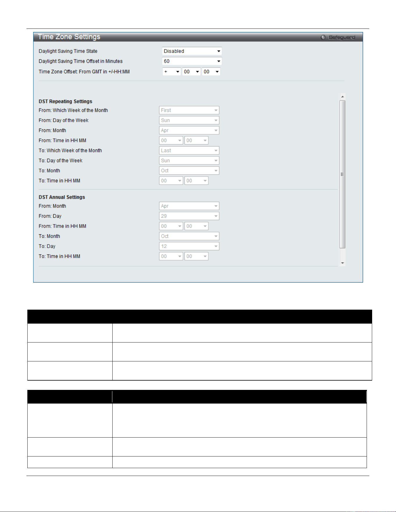
xStack® DGS-3420 Series Layer 2 Managed Stackable Gigabit Switch Web UI Reference Guide
390
Figure 9-41 Time Zone Settings window
The fields that can be configured are described below:
Parameter Description
Daylight Saving Time
State
Use this drop-down menu to enable or disable the DST Settings.
Daylight Saving Time
Offset In Minutes
Use this drop-down menu to specify the amount of time that will constitute your local
DST offset – 30, 60, 90, or 120 minutes.
Time Zone Offset From
GMT In +/- HH:MM
Use these drop-down menus to specify your local time zone’s offset from Greenwich
Mean Time (GMT.)
Parameter Description
DST Repeating Settings
Using repeating mode will enable DST seasonal time adjustment. Repeating mode
requires that the DST beginning and ending date be specified using a formula. For
example, specify to begin DST on Saturday during the second week of April and end
DST on Sunday during the last week of October.
From: Which Week Of
The Month
Enter the week of the month that DST will start.
From: Day Of Week
Enter the day of the week that DST will start on.

xStack® DGS-3420 Series Layer 2 Managed Stackable Gigabit Switch Web UI Reference Guide
391
From: Month
Enter the month DST will start on.
From: Time In HH:MM
Enter the time of day that DST will start on.
To: Which Week Of The
Month
Enter the week of the month the DST will end.
To: Day Of Week
Enter the day of the week that DST will end.
To: Month
Enter the month that DST will end.
To: Time In HH:MM
Enter the time DST will end.
Parameter Description
DST Annual Settings
Using annual mode will enable DST seasonal time adjustment. Annual mode requires
that the DST beginning and ending date be specified concisely. For example, specify
to begin DST on April 3 and end DST on October 14.
From: Month
Enter the month DST will start on, each year.
From: Day
Enter the day of the month DST will start on, each year.
From: Time In HH:MM
Enter the time of day DST will start on, each year.
To: Month
Enter the month DST will end on, each year.
To: Day
Enter the day of the month DST will end on, each year.
To: Time In HH:MM
Enter the time of day that DST will end on, each year.
Click the Apply button to accept the changes made.
UDP
UDP Helper
The UDP Helper forwards specific broadcasts to a server according to the UDP destination ports. It will decrease the
network traffic compared to a broadcast packet propagated to all the subnets.
UDP Helper Settings
On this page, the user can configure the UDP Helper settings.
To view this window, click Network Application > UDP > UDP Helper > UDP Helper Settings as shown below:
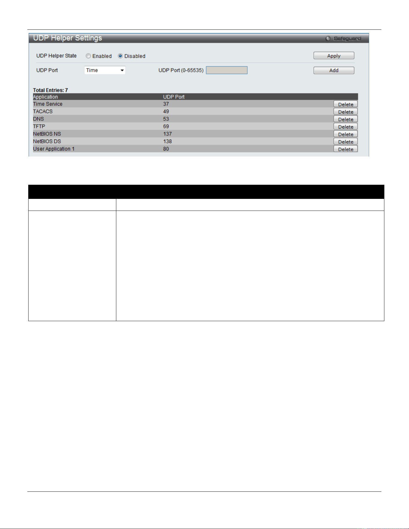
xStack® DGS-3420 Series Layer 2 Managed Stackable Gigabit Switch Web UI Reference Guide
392
Figure 9-42 UDP Helper Settings window
The fields that can be configured are described below:
Parameter Description
UDP Helper State
Specifies to enable or disable the UDP Helper function on the Switch.
UDP Port
This option is used to add a UDP port for the UDP Helper function on the Switch.
Time - Specifies the Time service. The UDP port number is 37.
TACACS - Specifies the Terminal Access Controller Access Control System service.
The UDP port number is 49.
DNS - Specifies the Domain Naming System service. The UDP port number is 53.
TFTP - Specifies the Trivial File Transfer Protocol service. The UDP port number is 69.
NetBIOS NS - Specifies the NetBIOS Name Server service. The UDP port number is
137.
NetBIOS DS - Specifies the NetBIOS Datagram Server service. The UDP port number
is 138.
UDP Port - Enter any UDP ports used for services not listed. This value must be
between 0 and 65535.
Click the Apply button to accept the changes made.
Click the Add button to add a new entry based on the information entered.
Click the Delete button to remove the specific entry.
UDP Helper Server Settings
On this page, the used can configure the UDP Helper Server settings.
To view this window, click Network Application > UDP > UDP Helper > UDP Helper Server Settings as shown
below:
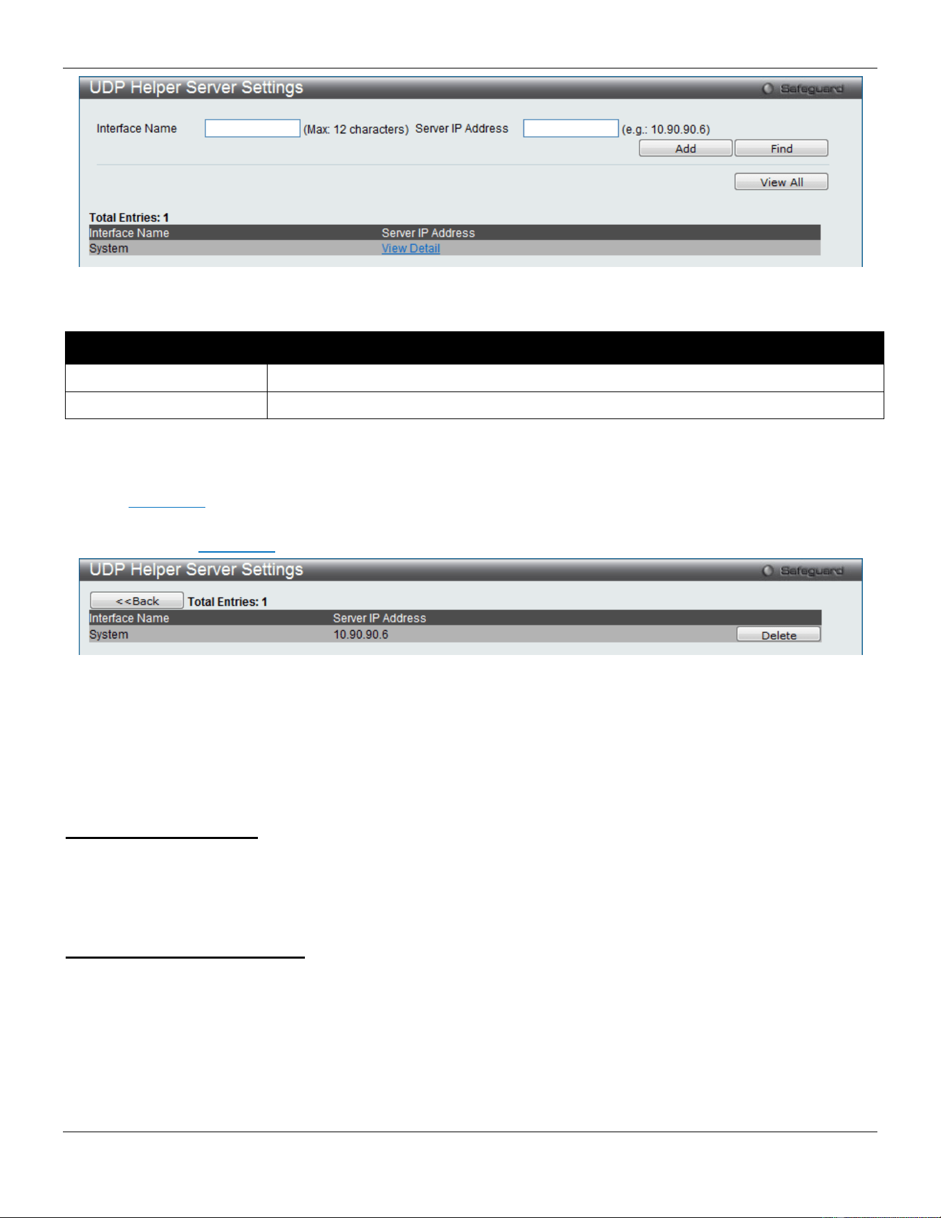
xStack® DGS-3420 Series Layer 2 Managed Stackable Gigabit Switch Web UI Reference Guide
393
Figure 9-43 UDP Helper Server Settings window
The fields that can be configured are described below:
Parameter Description
Interface Name
Enter the IP interface name used here. This name can be up to 12 characters long.
Server IP Address
Enter the UDP Helper Server IP address here.
Click the Add button to add a new entry based on the information entered.
Click the Find button to locate a specific entry based on the information entered.
Click the View All button to display all the existing entries.
Click the View Detail link to view more information regarding the specific entry.
After clicking in the View Detail link, the following window will appear:
Figure 9-44 UDP Helper Server Settings window (View Detail)
Click the Delete button to remove the specific entry.
Click the <<Back button to return to the previous page.
Flash File System Settings
Why use flash file system:
In old switch system, the firmware, configuration and log information are saved in a flash with fixed addresses and size.
This means that the maximum configuration file can only be 2Mb, and even if the current configuration is only 40Kb, it
will still take up 2Mb of flash storage space. The configuration file number and firmware numbers are also fixed. A
compatible issue will occur in the event that the configuration file or firmware size exceeds the originally designed size.
Flash File System in our system:
The Flash File System is used to provide the user with flexible file operation on the Flash. All the firmware,
configuration information and system log information are stored in the Flash as files. This means that the Flash space
taken up by all the files are not fixed, it is the real file size. If the Flash space is enough, the user could download more
configuration files or firmware files and use commands to display Flash file information, rename file names, and delete
it. Furthermore, the user can also configure the boot up runtime image or the running configuration file if needed.
In case the file system gets corrupted, Z-modem can be used to download the backup files directly to the system.
To view this window, click Network Application > Flash File System Settings as shown below:
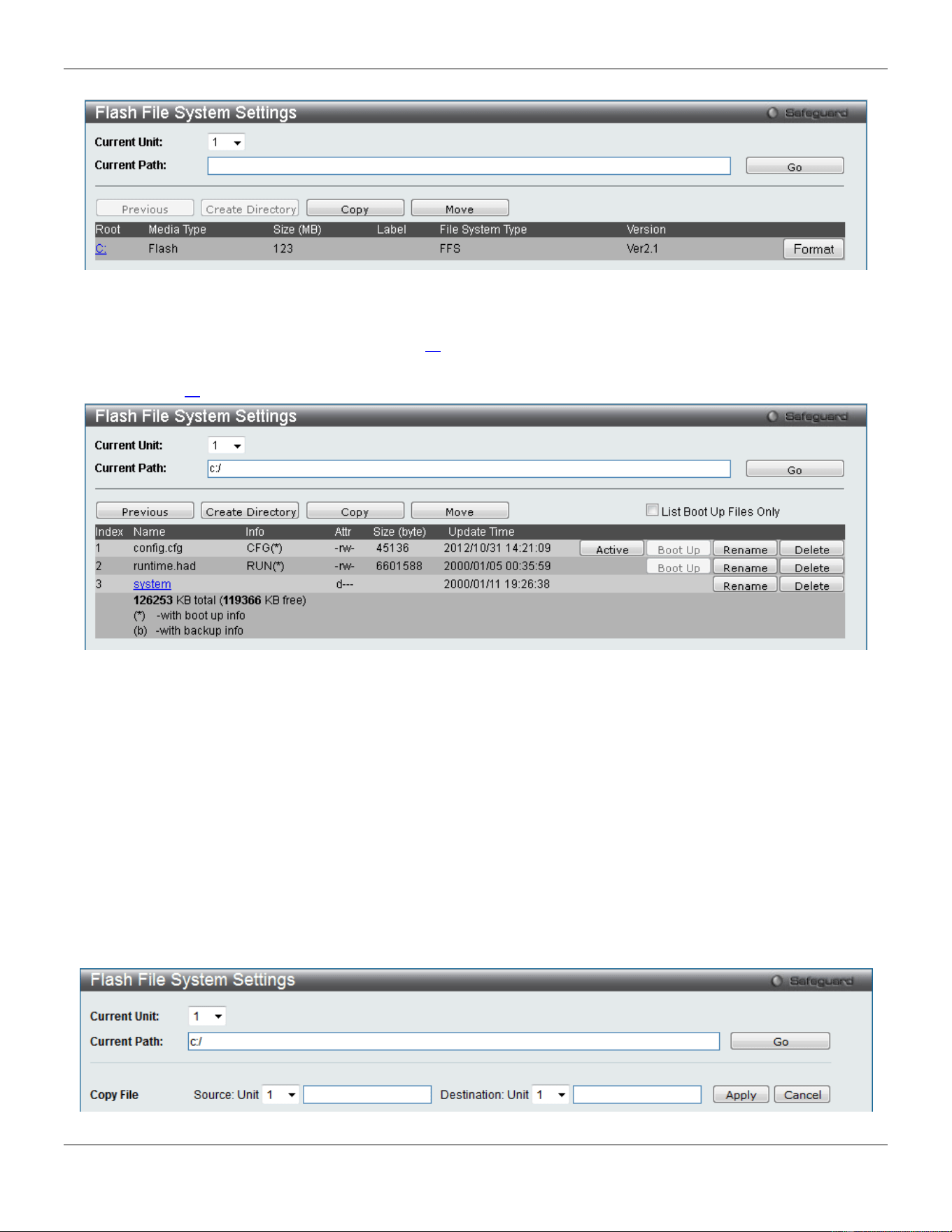
xStack® DGS-3420 Series Layer 2 Managed Stackable Gigabit Switch Web UI Reference Guide
394
Figure 9-45 Flash File System Settings window
Select the Current Unit ID and enter the Current Path string and click the Go button to navigate to the path entered.
Click the Format button to format the root. Click the C: link to navigate the C: drive.
After clicking the C: link button, the following page will appear:
Figure 9-46 Flash File System Setting – Search for Drive window
Click the Previous button to return to the previous page.
Click the Create Directory to create a new directory within the file system of the switch.
Click the Copy button to copy a specific file to the switch.
Click the Move button to move a specific file within the switch.
Tick the List Boot Up Files Only option to display only the boot up files.
Click the Active button to set a specific config file as the active runtime configuration.
Click the Boot Up button to set a specific runtime image or configuration as the boot up.
Click the Rename button to rename a specific file’s name.
Click the Delete button to remove a specific file from the file system.
Click the Copy button to see the following window.
Figure 9-47 Flash File System Settings – Copy window
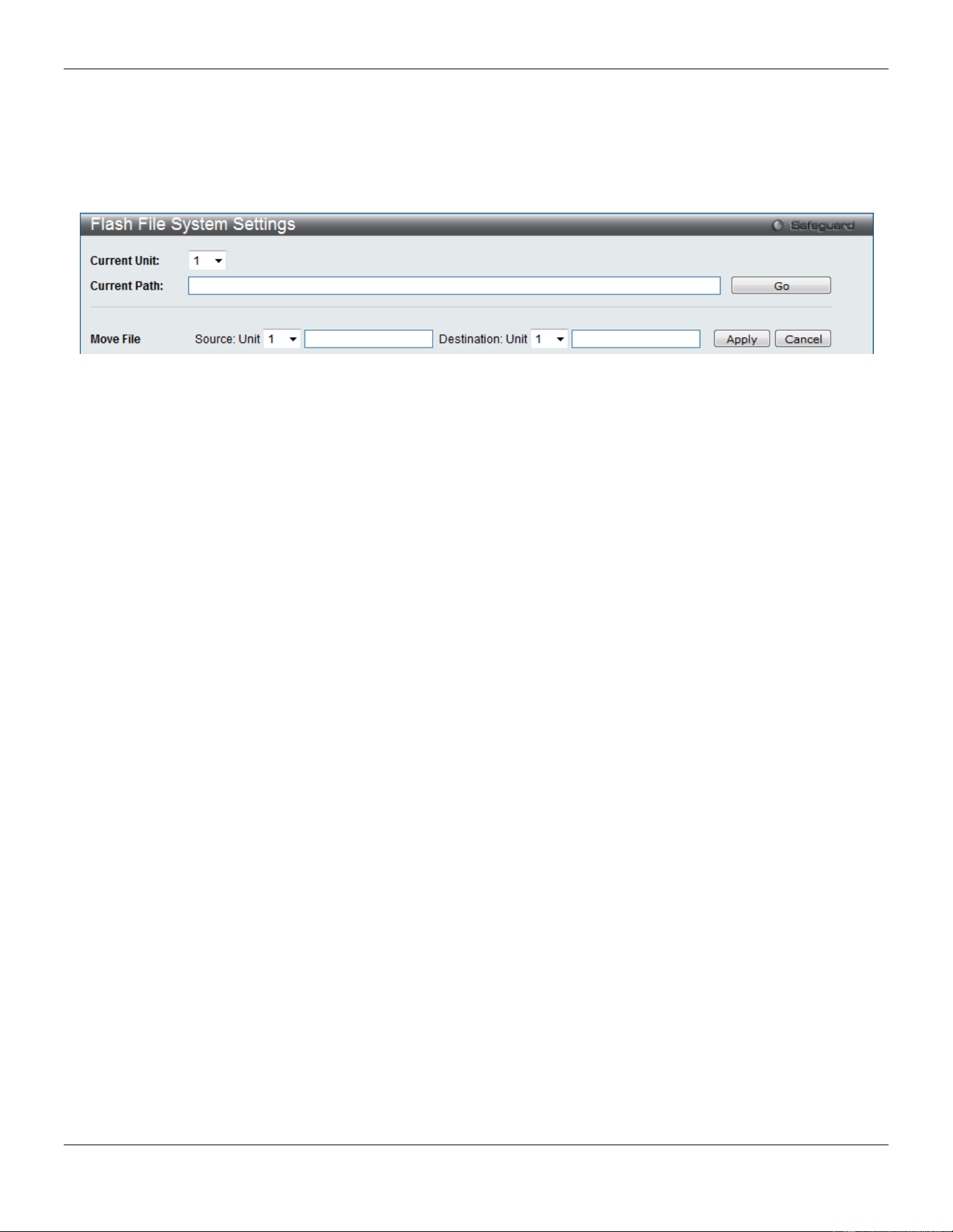
xStack® DGS-3420 Series Layer 2 Managed Stackable Gigabit Switch Web UI Reference Guide
395
When copying a file to the file system of this switch, the user must enter the Source and Destination path.
Click the Apply button to initiate the copy.
Click the Cancel button to discard the process.
Click the Move button to see the following window
Figure 9-48 Flash File System Settings – Move window
When moving a file to another place, the user must enter the Source and Destination path.
Click the Apply button to initiate the copy.
Click the Cancel button to discard the process.
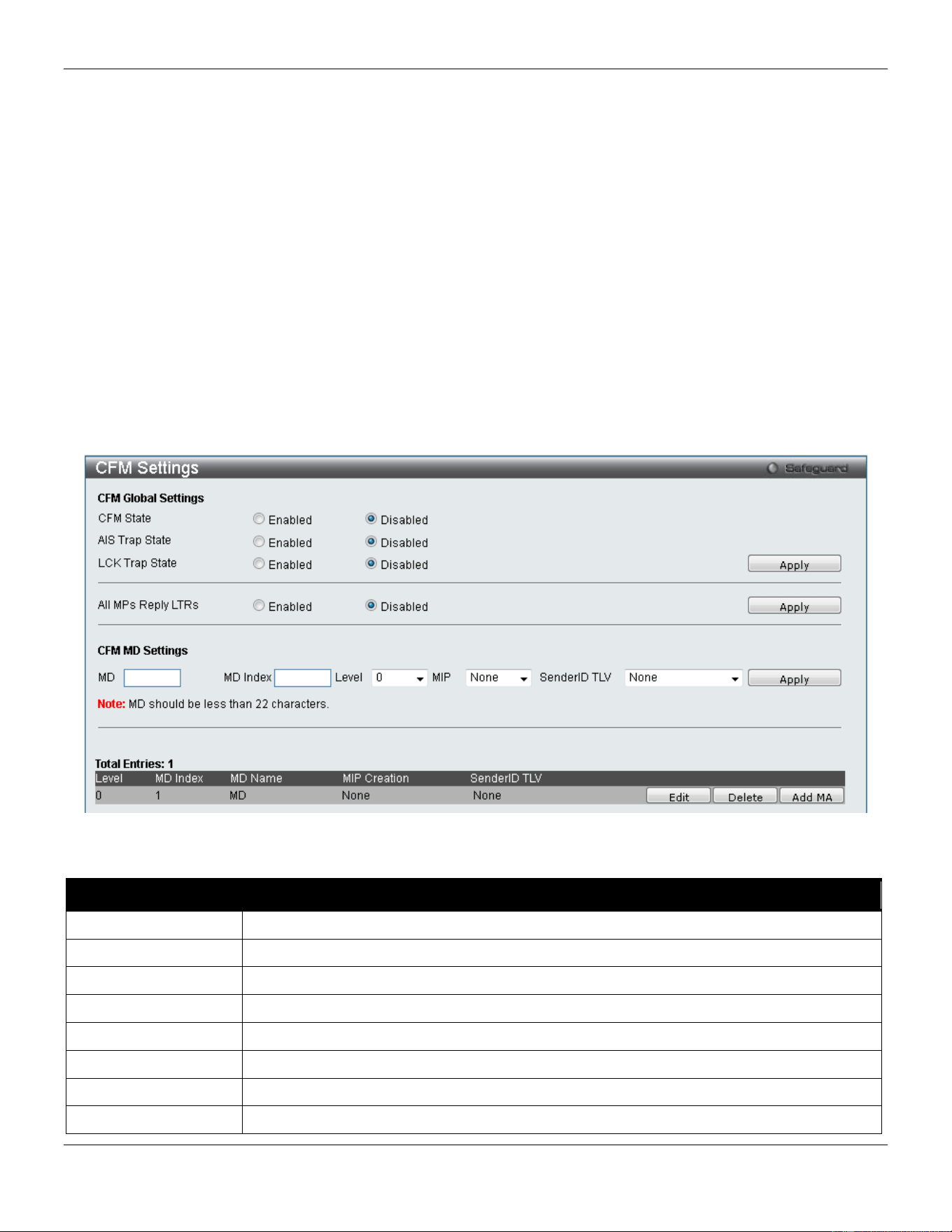
xStack® DGS-3420 Series Layer 2 Managed Stackable Gigabit Switch Web UI Reference Guide
396
Chapter 10 OAM
CFM
Ethernet OAM
DULD Settings
Cable Diagnostics
CFM
CFM Settings
On this page the user can configure the CFM parameters.
To view this window, click OAM > CFM > CFM Settings, as shown below:
Figure 10-1 CFM Settings Window
The fields that can be configured are described below:
Parameter Description
CFM State
Click the radio buttons to enable or disable the CFM feature.
AIS Trap State
Click to enable or disable the AIS trap state.
LCK Trap State
Click to enable or disable the LCK trap state.
All MPs Reply LTRs
Click the radio buttons to enable or disable all MPs to reply LTRs.
MD
Enter the maintenance domain name.
MD Index
Enter the maintenance domain index used.
Level
Use the drop-down menu to select the maintenance domain level.
MIP
This is the control creations of MIPs.
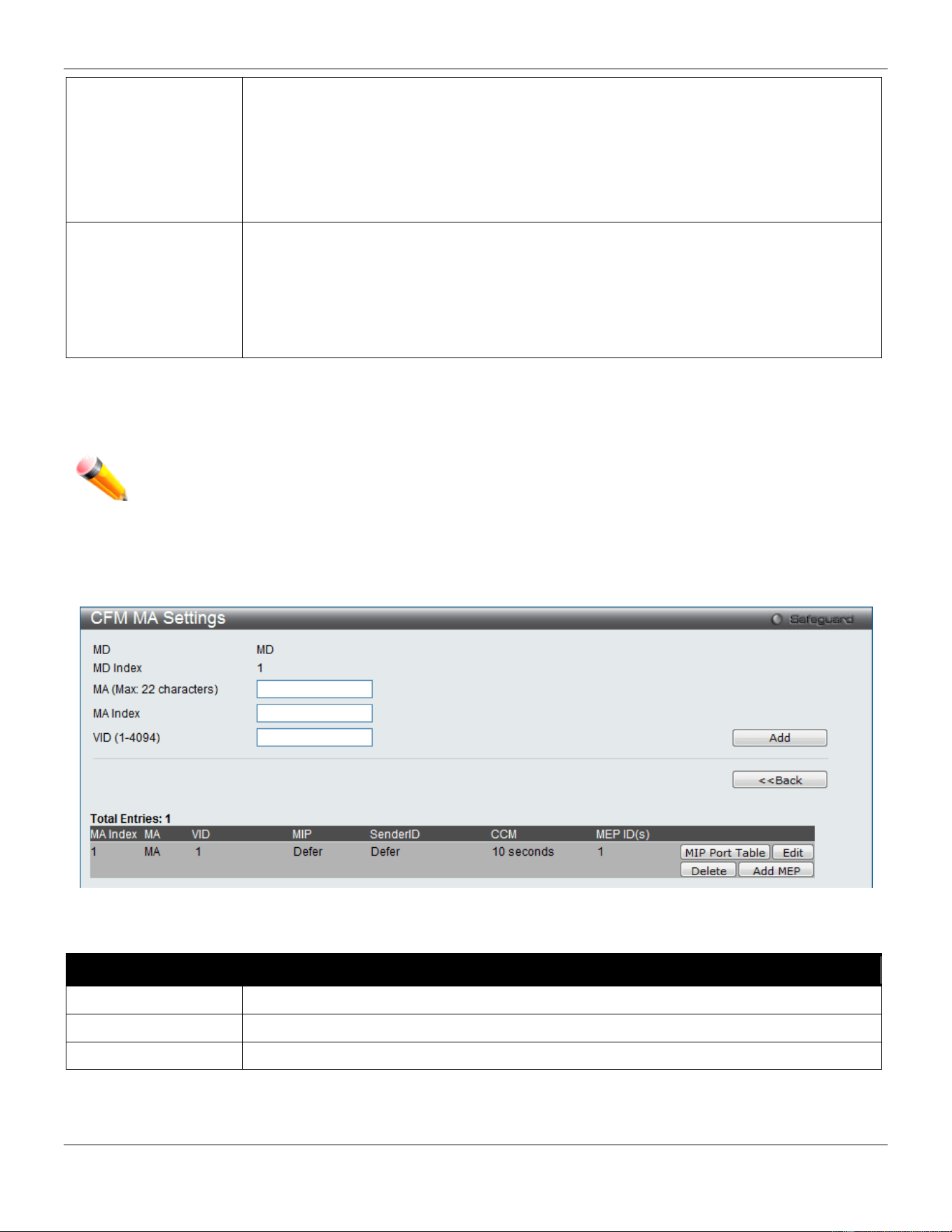
xStack® DGS-3420 Series Layer 2 Managed Stackable Gigabit Switch Web UI Reference Guide
397
None – Don’t create MIPs. This is the default value.
Auto – MIPs can always be created on any ports in this MD, if that port is not configured
with an MEP of this MD. For the intermediate switch in an MA, the setting must be auto in
order for the MIPs to be created on this device.
Explicit – MIPs can be created on any ports in this MD, only if the next existent lower level
has an MEP configured on that port, and that port is not configured with an MEP of this
MD.
SenderID TLV
This is the control transmission of the SenderID TLV.
None – Don’t transmit sender ID TLV. This is the default value.
Chassis – Transmit sender ID TLV with chassis ID information.
Manage – Transmit sender ID TLV with managed address information.
Chassis Manage – Transmit sender ID TLV with chassis ID information and manage
address information.
Click the Apply button to accept the changes made for each individual section.
Click the Edit button to re-configure the specific entry.
Click the Delete button to remove the specific entry.
NOTE: The MD Name value should not be more than 22 characters.
To add a maintenance association (MA), click the Add MA button.
Click the Add MA button to see the following window
Figure 10-2 CFM MA Settings Window
The fields that can be configured are described below:
Parameter Description
MA
Enter the maintenance association name.
MA Index
Enter the maintenance association index.
VID
VLAN Identifier. Different MA must be associated with different VLANs.
Click the Add button to add a new entry based on the information entered.
Click the <<Back button to discard the changes made and return to the previous page.
Click the Edit button to re-configure the specific entry.
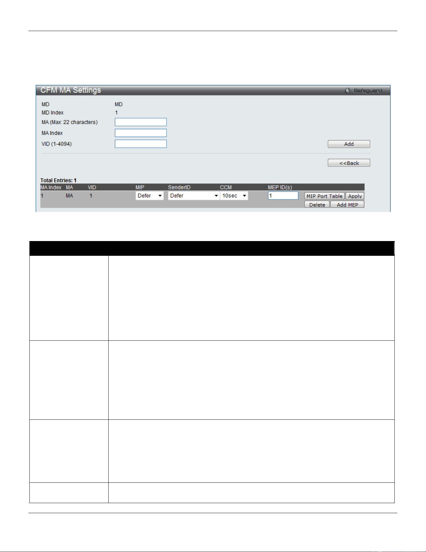
xStack® DGS-3420 Series Layer 2 Managed Stackable Gigabit Switch Web UI Reference Guide
398
Click the Delete button to remove the specific entry.
Click the MIP Port Table button to view the CFM MIP Table.
Click the Add MEP button to add a Maintenance End Point entry.
After clicking the Edit button, the following window appears:
Figure 10-3 CFM MA Settings (Edit) Window
The fields that can be configured are described below:
Parameter Description
MIP
This is the control creation of MIPs.
None - Don’t create MIPs.
Auto - MIPs can always be created on any ports in this MA, if that port is not configured
with an MEP of that MA.
Explicit - MIP can be created on any ports in this MA, only if the next existent lower level
has an MEP configured on that port, and that port is not configured with an MEP of this
MA.
Defer - Inherit the setting configured for the maintenance domain that this MA is
associated with. This is the default value.
SenderID
This is the control transmission of the sender ID TLV.
None - Don’t transmit sender ID TLV. This is the default value.
Chassis - Transmit sender ID TLV with chassis ID information.
Manage - Transmit sender ID TLV with manage address information.
Chassis Manage - Transmit sender ID TLV with chassis ID information and manage
address information.
Defer - Inherit the setting configured for the maintenance domain that this MA is
associated with. This is the default value.
CCM
This is the CCM interval.
100ms - 100 milliseconds. Not recommended. For test purpose.
1sec - One second.
10sec - Ten seconds. This is the default value.
1min - One minute.
10min - Ten minutes.
MEP ID(s)
This is to specify the MEP IDs contained in the maintenance association. The range of the
MEP ID is 1-8191.
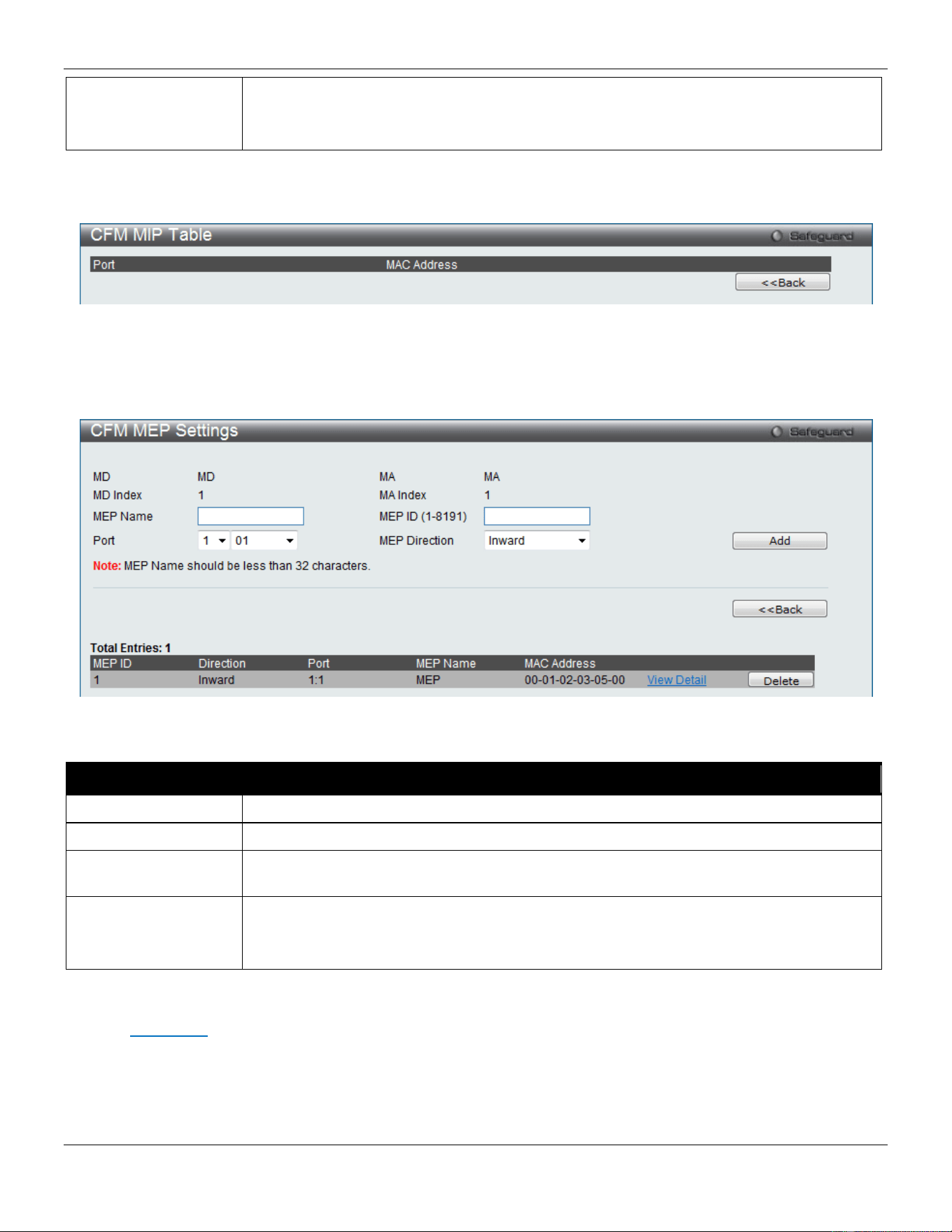
xStack® DGS-3420 Series Layer 2 Managed Stackable Gigabit Switch Web UI Reference Guide
399
Add - Add MEP ID(s).
Delete - Delete MEP ID(s).
By default, there is no MEP ID in a newly created maintenance association.
Click the Apply button to accept the changes made.
After clicking the MIP Port Table button, the following page will appear:
Figure 10-4 CFM MIP Port Table Window
Click the <<Back button to return to the previous page.
After clicking the Add MEP button, the following page will appear:
Figure 10-5 CFM MEP Settings (Add) Window
The fields that can be configured are described below:
Parameter Description
MEP Name
Enter an MEP name. It is unique among all MEPs configured on the device.
MEP ID (1-8191)
Enter an MEP ID configured in the MA’s MEP ID list.
Port
Use the drop-down menu to select a unit ID and port number. This port should be a
member of the MA’s associated VLAN.
MEP Direction
This is the MEP direction.
Inward - Inward facing (up) MEP.
Outward - Outward facing (down) MEP.
Click the Add button to add a new entry based on the information entered.
Click the <<Back button to discard the changes made and return to the previous page.
Click the View Detail link to view more information regarding the specific entry.
Click the Delete button to remove the specific entry.
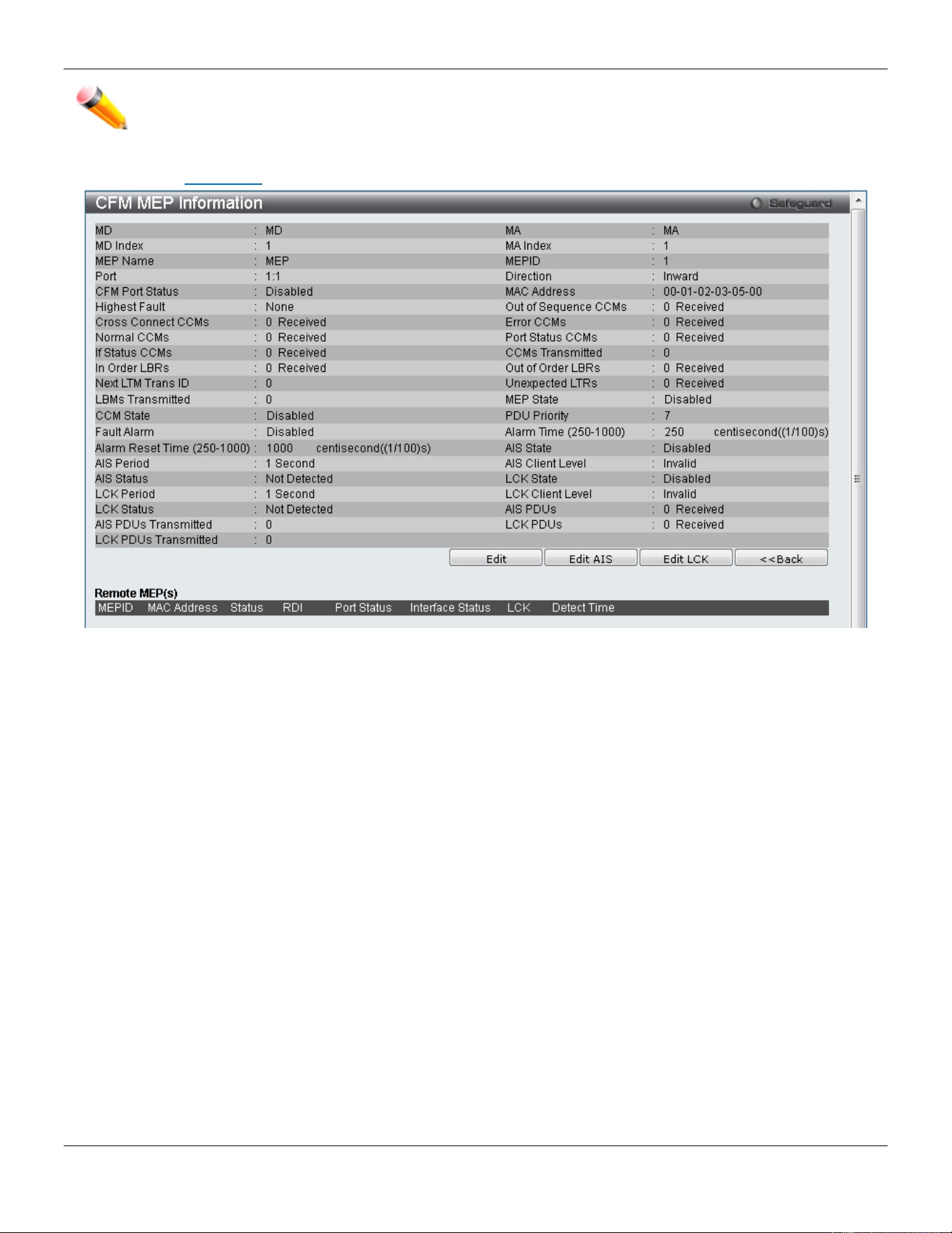
xStack® DGS-3420 Series Layer 2 Managed Stackable Gigabit Switch Web UI Reference Guide
400
NOTE: The MEP Name value should not be more than 32 characters.
After clicking the View Detail link, the following page will appear:
Figure 10-6 CFM MEP Information Window
Click the Edit button to re-configure the specific entry.
Click the <<Back button to discard the changes made and return to the previous page.
After clicking the Edit button, the following page will appear:
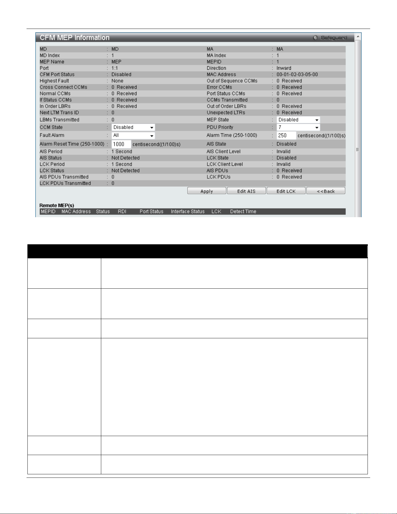
xStack® DGS-3420 Series Layer 2 Managed Stackable Gigabit Switch Web UI Reference Guide
401
Figure 10-7 CFM MEP Information (Edit) Window
The fields that can be configured are described below:
Parameter Description
MEP State
This is the MEP administrative state.
Enable - MEP is enabled.
Disable - MEP is disabled. This is the default value.
CCM State
This is the CCM transmission state.
Enable - CCM transmission enabled.
Disable - CCM transmission disabled. This is the default value.
PDU Priority
The 802.1p priority is set in the CCMs and the LTMs messages transmitted by the MEP.
The default value is 7.
Fault Alarm
This is the control types of the fault alarms sent by the MEP.
All - All types of fault alarms will be sent.
MAC Status - Only the fault alarms whose priority is equal to or higher than “Some
Remote MEP MAC Status Error” are sent.
Remote CCM - Only the fault alarms whose priority is equal to or higher than “Some
Remote MEP Down” are sent.
Errors CCM - Only the fault alarms whose priority is equal to or higher than “Error CCM
Received” are sent.
Xcon CCM - Only the fault alarms whose priority is equal to or higher than “Cross-connect
CCM Received” are sent.
None - No fault alarm is sent. This is the default value.
Alarm Time
This is the time that a defect must exceed before the fault alarm can be sent. The unit is in
centiseconds, the range is 250-1000. The default value is 250.
Alarm Reset Time
This is the dormant duration time before a defect is triggered before the fault can be re-
alarmed. The unit is in centiseconds, the range is 250-1000. The default value is 1000.
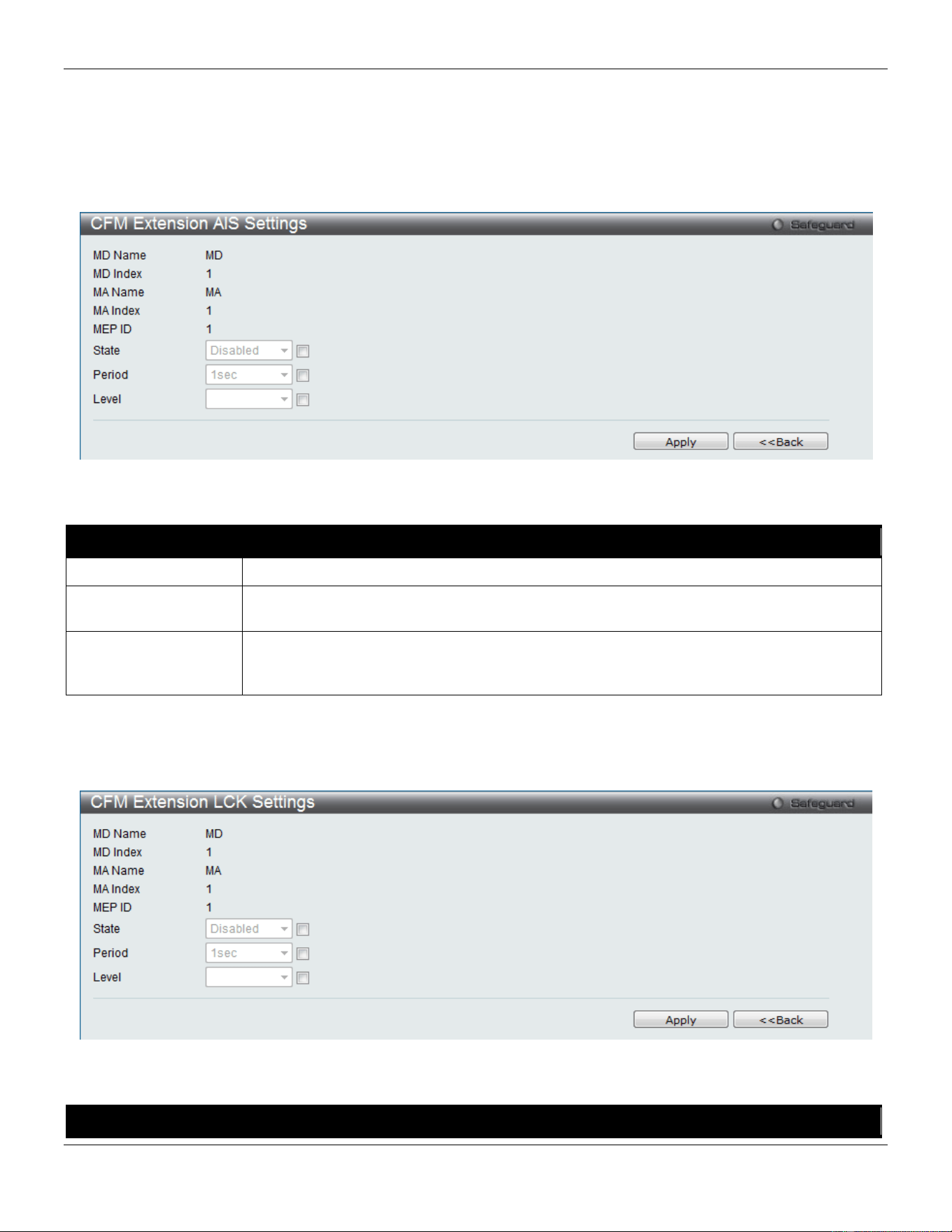
xStack® DGS-3420 Series Layer 2 Managed Stackable Gigabit Switch Web UI Reference Guide
402
Click the Apply button to accept the changes made.
Click the <<Back button to discard the changes made and return to the previous page.
Click the Edit AIS button to configure the AIS settings.
Click the Edit LCK button to configure the LCK settings.
After clicking the Edit AIS button, the following window will appear:
Figure 10-8 CFM Extension AIS (Edit) Window
The fields that can be configured are described below:
Parameter Description
State
Tick the check box and use the drop-down menu to enable or disable the AIS function.
Period
Tick the check box and use the drop-down menu to select the transmitting interval of AIS
PDU.
Level
Tick the check box and use the drop-down menu to select the client level ID to which the
MEP sends AIS PDU. The default client MD level is MD level at which the most immediate
client layer MIPs and MEPs exist. Options to choose from are values between 0 and 7.
Click the Apply button to accept the changes made.
Click the <<Back button to discard the changes made and return to the previous page.
After click the Edit LCK button, the following window will appear:
Figure 10-9 CFM Extension LCK Settings (Edit) Window
The fields that can be configured are described below:
Parameter Description
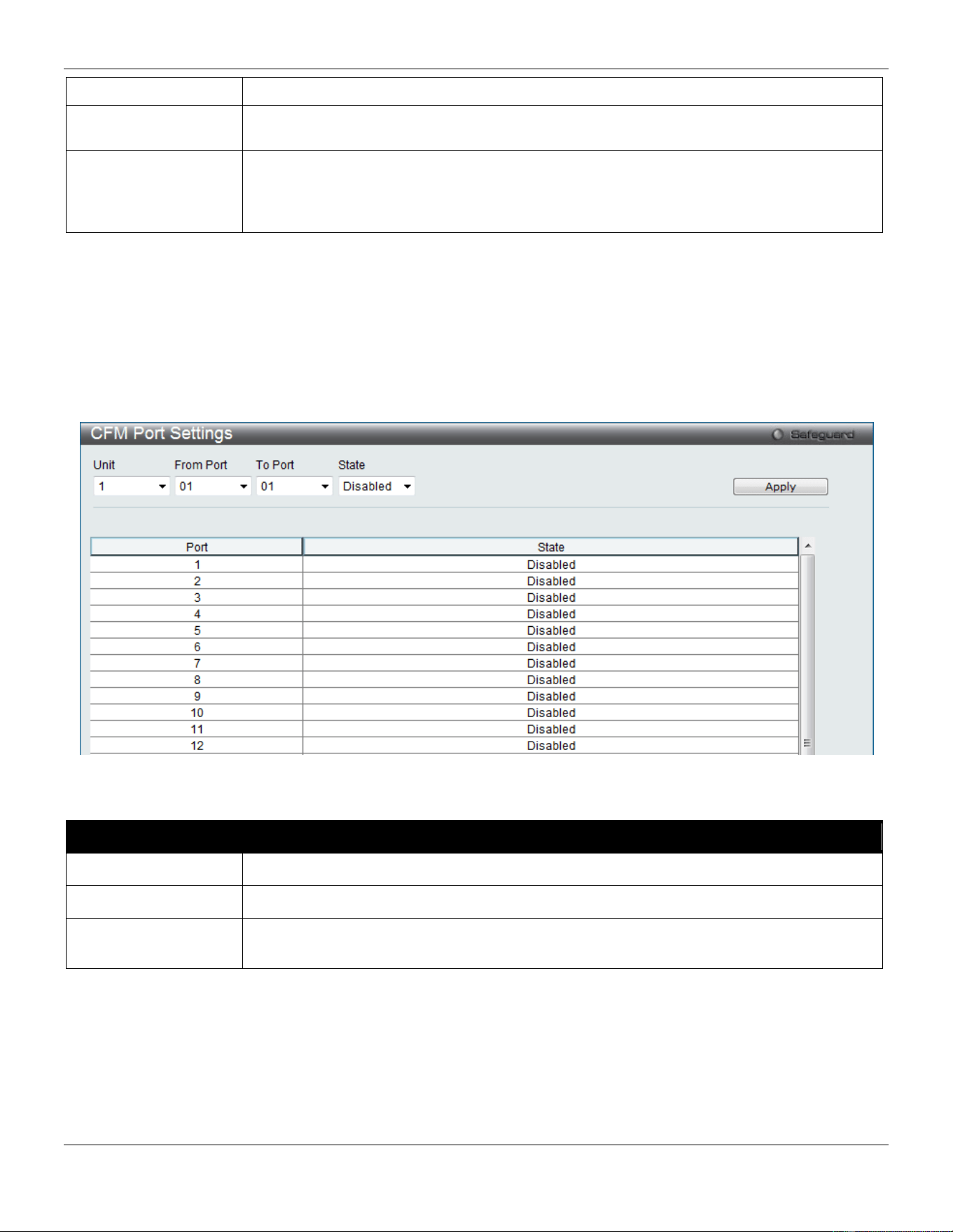
xStack® DGS-3420 Series Layer 2 Managed Stackable Gigabit Switch Web UI Reference Guide
403
State
Tick the check box and use the drop-down menu to enable or disable the LCK function.
Period
Tick the check box and use the drop-down menu to select the transmitting interval of LCK
PDU.
Level
Tick the check box and use the drop-down menu to select the client level ID to which the
MEP sends LCK PDU. The default client MD level is MD level at which the most
immediate client layer MIPs and MEPs exist. Options to choose from are values between
0 and 7.
Click the Apply button to accept the changes made.
Click the <<Back button to discard the changes made and return to the previous page.
CFM Port Settings
This window is used to configure the CFM port state.
To view this window, click OAM > CFM > CFM Port Settings, as shown below:
Figure 10-10 CFM Port Settings Window
The fields that can be configured are described below:
Parameter Description
Unit
Select the unit you wish to configure.
From Port / To Port
Use the drop-down menu to select a range of ports used for this configuration.
State
Use the drop-down menu to enable or disable the state of specific port regarding the CFM
configuration.
Click the Apply button to accept the changes made.
CFM MIPCCM Table
This window is used to display CFM MIPCCM information.
To view this window, click OAM > CFM > CFM MIPCCM Table, as shown below:
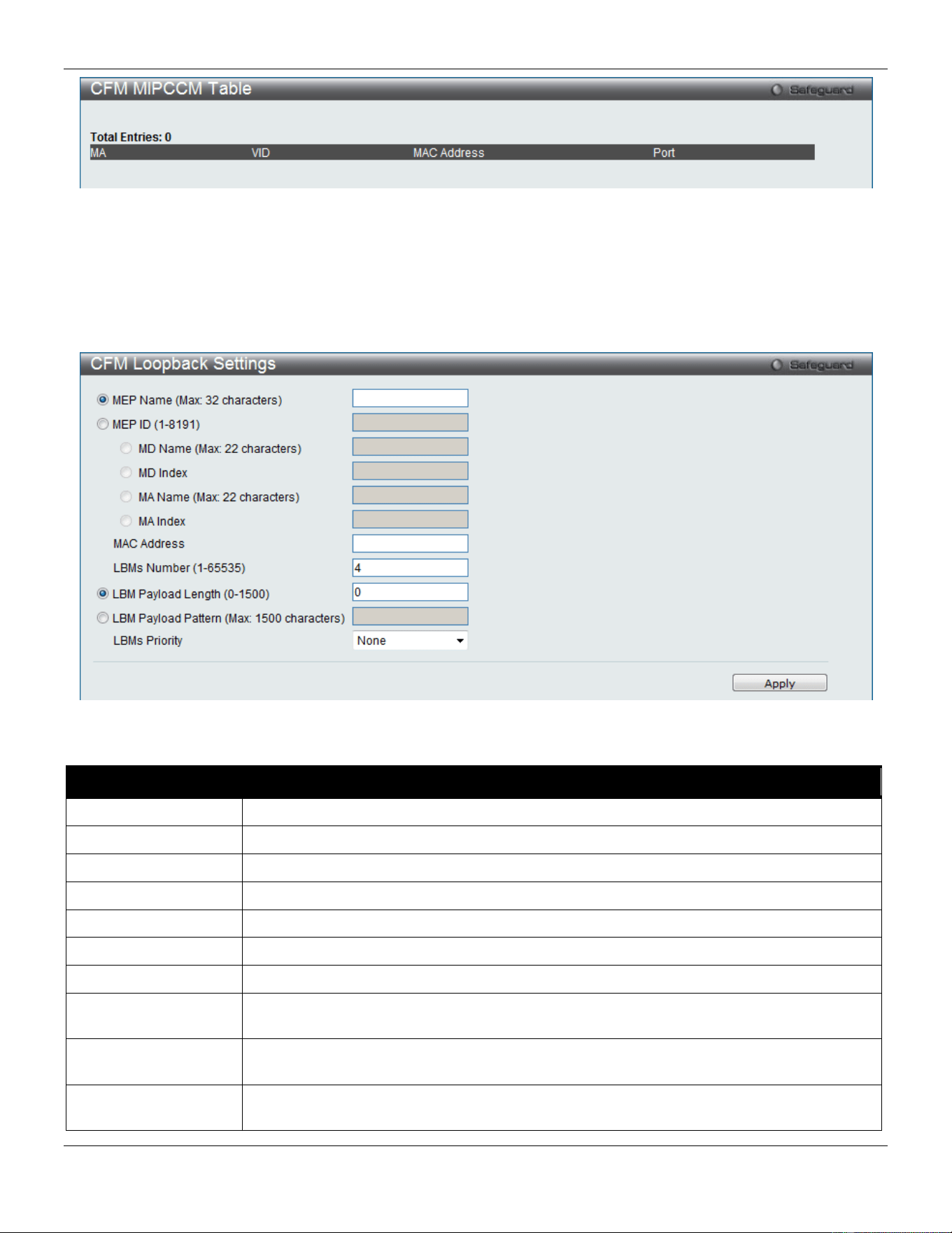
xStack® DGS-3420 Series Layer 2 Managed Stackable Gigabit Switch Web UI Reference Guide
404
Figure 10-11 CFM MIPCCM Table Window
CFM Loopback Settings
This window is used to CFM loopback settings.
To view this window, click OAM > CFM > CFM Loopback Settings, as shown below:
Figure 10-12 CFM Loopback Settings Window
The fields that can be configured are described below:
Parameter Description
MEP Name
Select and enter the Maintenance End Point name used.
MEP ID (1-8191)
Select and enter the Maintenance End Point ID used.
MD Name
Select and enter the Maintenance Domain name used.
MD Index
Select and enter the Maintenance Domain index used.
MA Name
Select and enter the Maintenance Association name used.
MA Index
Select and enter the Maintenance Association index used.
MAC Address
Enter the destination MAC address used here.
LBMs Number (1-
65535)
Number of LBMs to be sent. The default value is 4.
LBM Payload Length
(0-1500)
The payload length of LBM to be sent. The default is 0.
LBM Payload Pattern
An arbitrary amount of data to be included in a Data TLV, along with an indication whether
the Data TLV is to be included.
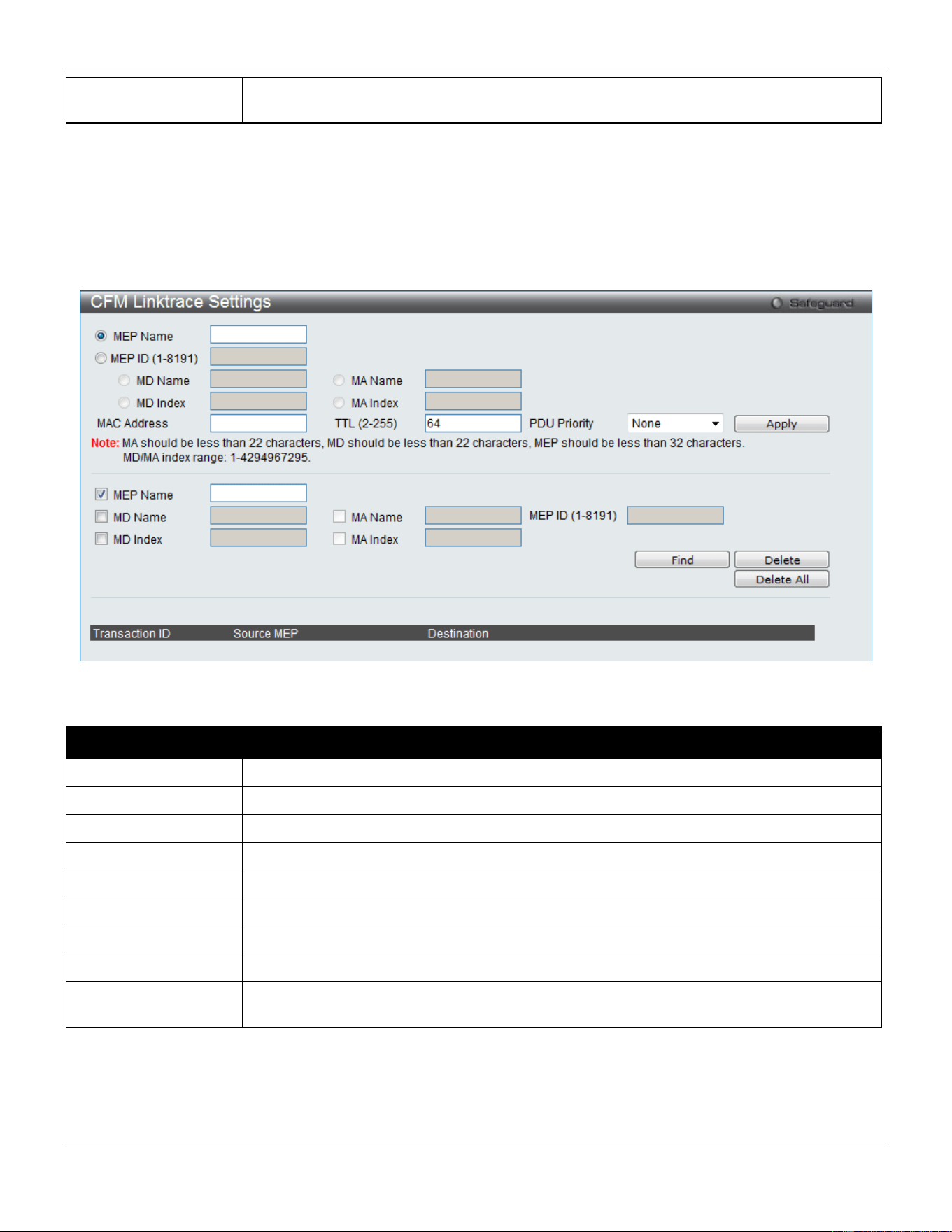
xStack® DGS-3420 Series Layer 2 Managed Stackable Gigabit Switch Web UI Reference Guide
405
LBMs Priority
The 802.1p priority to be set in the transmitted LBMs. If not specified, it uses the same
priority as CCMs and LTMs sent by the MA.
Click the Apply button to accept the changes made.
CFM Linktrace Settings
This window is used to configure the CFM linktrace settings.
To view this window, click OAM > CFM > CFM Linktrace Settings, as shown below:
Figure 10-13 CFM Linktrace Settings Window
The fields that can be configured are described below:
Parameter Description
MEP Name
Select and enter the Maintenance End Point name used.
MEP ID (1-8191)
Select and enter the Maintenance End Point ID used.
MD Name
Select and enter the Maintenance Domain name used.
MD Index
Select and enter the Maintenance Domain index used.
MA Name
Select and enter the Maintenance Association name used.
MA Index
Select and enter the Maintenance Association index used.
MAC Address
Here the user can enter the destination MAC address.
TTL
Link-trace message TTL value. The default value is 64.
PDU Priority
The 802.1p priority to be set in the transmitted LTM. If not specified, it uses the same
priority as CCMs sent by the MA.
Click the Apply button to accept the changes made.
Click the Find button to locate a specific entry based on the information entered.
Click the Delete button to remove the specific entry based on the information entered.
Click the Delete All button to remove all the entries listed.
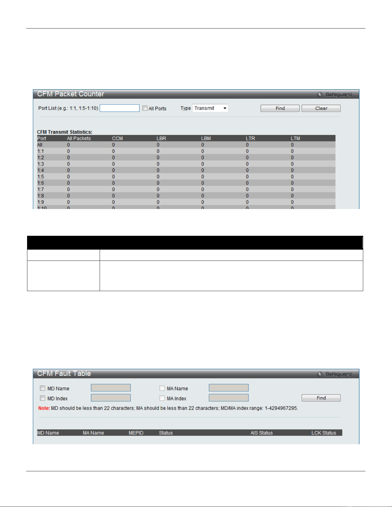
xStack® DGS-3420 Series Layer 2 Managed Stackable Gigabit Switch Web UI Reference Guide
406
CFM Packet Counter
This window is used to display the CFM packet counter information.
To view this window, click OAM > CFM > CFM Packet Counter, as shown below:
Figure 10-14 CFM Packet Counter Window
The fields that can be configured are described below:
Parameter Description
Port List
Enter a port or range of ports to display. Tick the All Ports check box to display all ports.
Type Transmit – Selecting this option will display all the CFM packets transmitted.
Receive – Selecting this option will display all the CFM packets received.
CCM – Selecting this option will display all the CFM packets transmitted and received.
Click the Find button to locate a specific entry based on the information entered.
Click the Clear button to clear all the information entered in the fields.
CFM Fault Table
This window is used to display the CFM fault information.
To view this window, click OAM > CFM > CFM Fault Table, as shown below:
Figure 10-15 CFM Fault Table Window
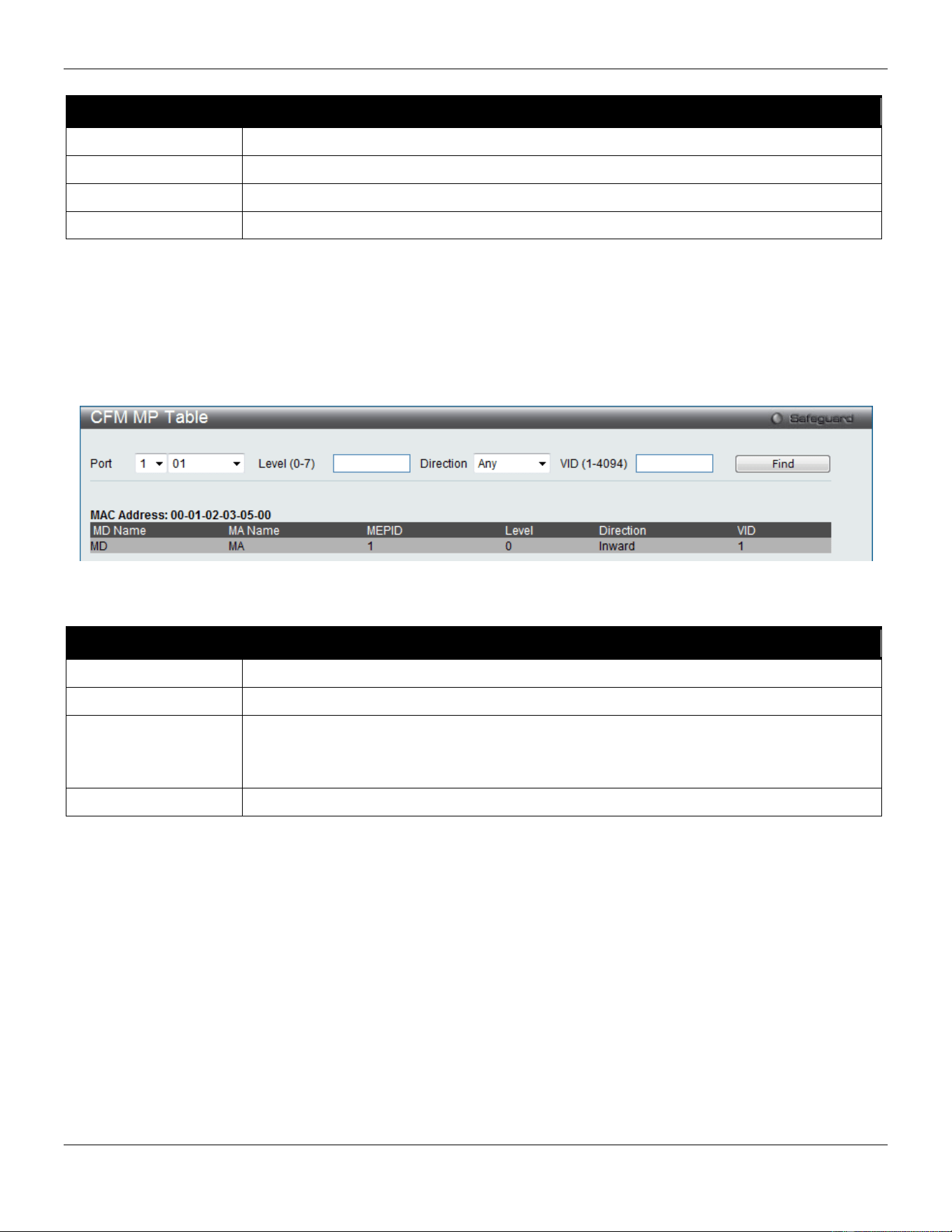
xStack® DGS-3420 Series Layer 2 Managed Stackable Gigabit Switch Web UI Reference Guide
407
The fields that can be configured are described below:
Parameter Description
MD Name
Select and enter the Maintenance Domain name used.
MD Index
Select and enter the Maintenance Domain index used.
MA Name
Select and enter the Maintenance Association name used.
MA Index
Select and enter the Maintenance Association index used.
Click the Find button to locate a specific entry based on the information entered.
CFM MP Table
This window is used to display the CFM MP information.
To view this window, click OAM > CFM > CFM MP Table, as shown below:
Figure 10-16 CFM MP Table Window
The fields that can be configured are described below:
Parameter Description
Port
Use the drop-down menu to select the unit ID and the port number to view.
Level
Enter the level to view.
Direction
Use the drop-down menu to select the direction to view.
Inward - Inward facing (up) MP.
Outward - Outward facing (down) MP.
VID
Enter the VLAN ID to view.
Click the Find button to locate a specific entry based on the information entered.
Ethernet OAM
Ethernet OAM Settings
This window is used to configure the Ethernet OAM settings.
To view this window, click OAM > Ethernet OAM > Ethernet OAM Settings, as shown below:
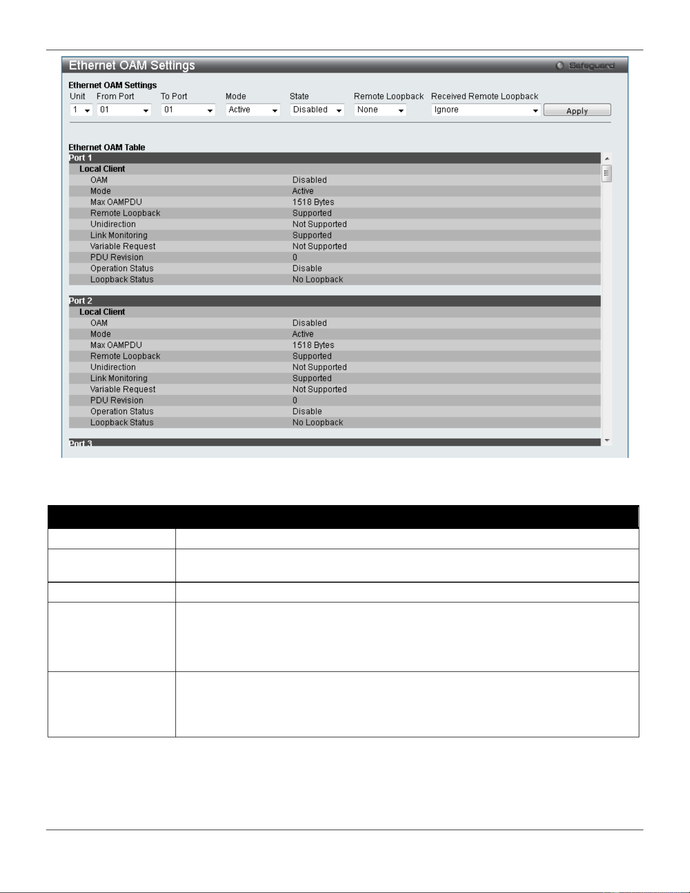
xStack® DGS-3420 Series Layer 2 Managed Stackable Gigabit Switch Web UI Reference Guide
408
Figure 10-17 Ethernet OAM Settings window
The fields that can be configured are described below:
Parameter Description
From Port / To Port
Select a range of ports you wish to configure.
Mode Use the drop-down menu to select to operate in either Active or Passive. The default
mode is Active.
State
Use the drop-down menu to enable or disable the OAM function.
Remote Loopback
Use the drop-down menu to select Ethernet OAM remote loopback.
None – Select to disable the remote loopback.
Start – Select to request the peer to change to the remote loopback mode.
Stop - Select to request the peer to change to the normal operation mode.
Received Remote
Loopback
Use the drop-down menu to configure the client to process or to ignore the received
Ethernet OAM remote loopback command.
Process – Select to process the received Ethernet OAM remote loopback command.
Ignore - Select to ignore the received Ethernet OAM remote loopback command.
Click the Apply button to accept the changes made for each individual section.
Ethernet OAM Configuration Settings
This window is used to configure Ethernet OAM configuration settings.
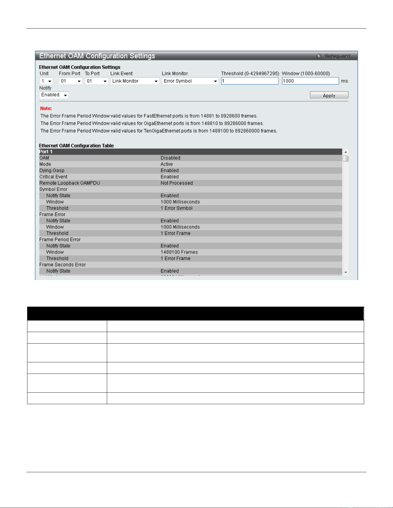
xStack® DGS-3420 Series Layer 2 Managed Stackable Gigabit Switch Web UI Reference Guide
409
To view this window, click OAM > Ethernet OAM > Ethernet OAM Configuration Settings, as shown below:
Figure 10-18 Ethernet OAM Configuration Settings window
The fields that can be configured are described below:
Parameter Description
From Port / To Port
Select a range of ports you wish to configure.
Link Event
Use the drop-down menu to select the link events, Link Monitor or Critical Link Event.
Link Monitor Use the drop-down menu to select link monitor. Available options are Error Symbol,
Error Frame, Error Frame Period, and Error Frame Seconds.
Critical Link Event
Use the drop-down menu to select between Dying Gasp and Critical Event.
Threshold
Enter the number of error frame or symbol in the period is required to be equal to or
greater than in order for the event to be generated.
Window
Enter the period of error frame or symbol in milliseconds summary event.
Click the Apply button to accept the changes made for each individual section.
Ethernet OAM Event Log
The window is used to show ports Ethernet OAM event log information.
To view this window, click OAM > Ethernet OAM > Ethernet OAM Event Log, as shown below:
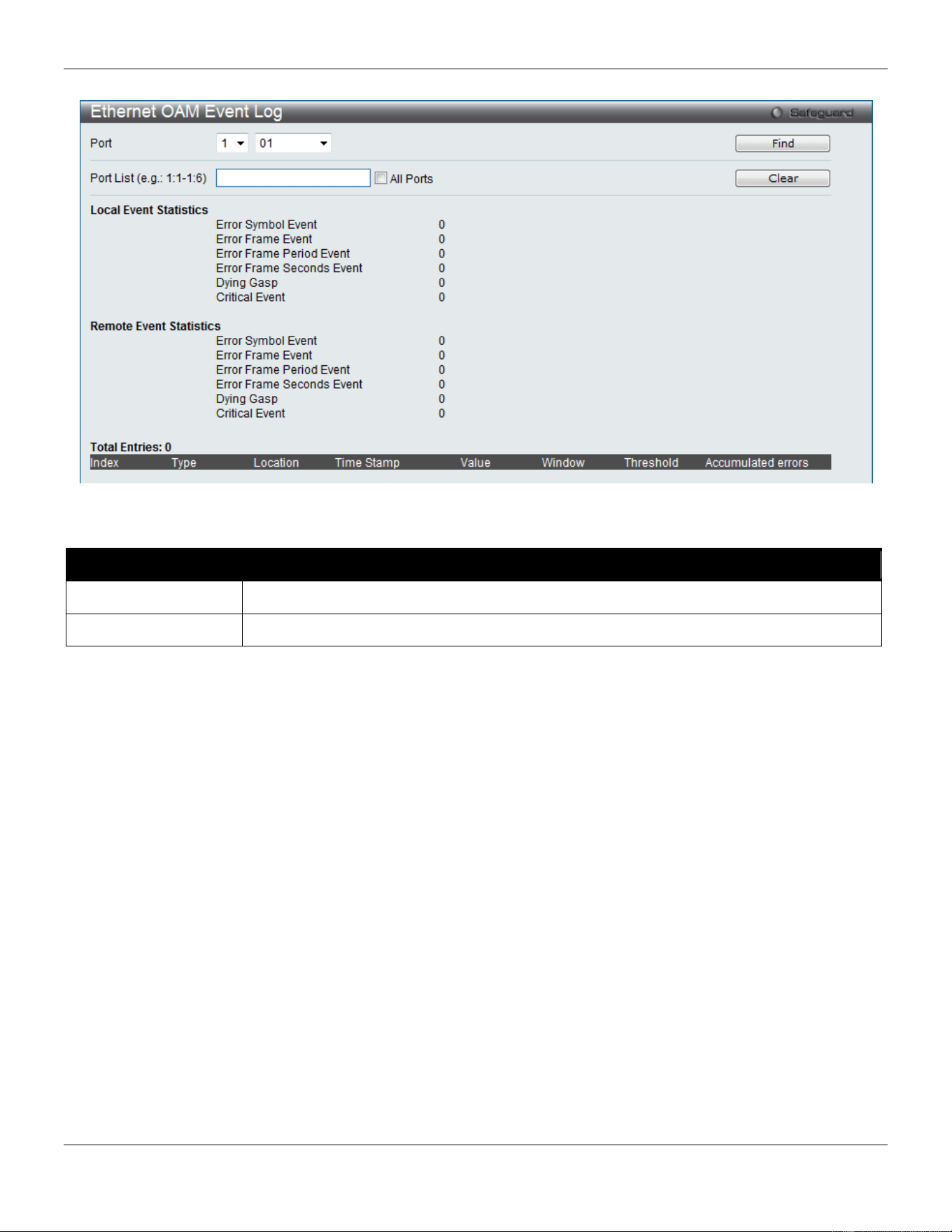
xStack® DGS-3420 Series Layer 2 Managed Stackable Gigabit Switch Web UI Reference Guide
410
Figure 10-19 Ethernet OAM Event Log window
The fields that can be configured are described below:
Parameter Description
Port
Use the drop-down menu to select the unit ID and the port number to view.
Port List Enter a list of ports. Tick the All Ports check box to select all ports.
Click the Find button to locate a specific entry based on the information entered.
Click the Clear button to clear all the information entered in the fields.
Ethernet OAM Statistics
The window is used to show ports Ethernet OAM statistics information.
To view this window, click OAM > Ethernet OAM > Ethernet OAM Statistics, as shown below:
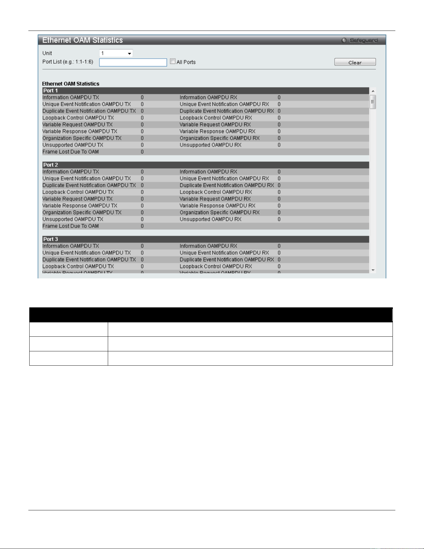
xStack® DGS-3420 Series Layer 2 Managed Stackable Gigabit Switch Web UI Reference Guide
411
Figure 10-20 Ethernet OAM Statistics window
The fields that can be configured are described below:
Parameter Description
Unit
Select the unit you wish to configure.
Port
Use the drop-down menu to select the unit ID and the port number to view.
Port List Enter a list of ports. Tick the All Ports check box to select all ports.
Click the Clear button to clear all the information entered in the fields.
DULD Settings
This window is used to configure and display the unidirectional link detection on port.
To view this window, click OAM > DULD Settings as shown below:
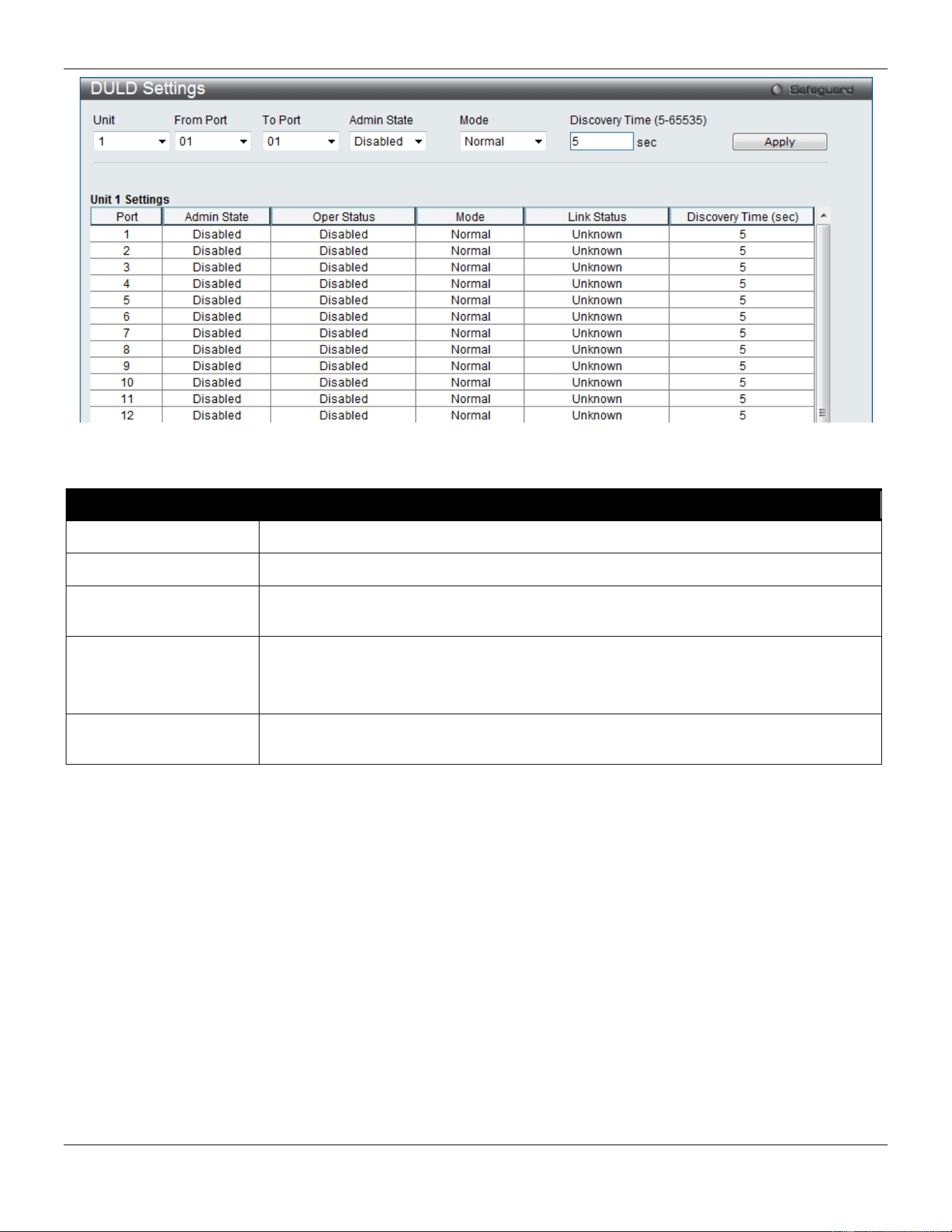
xStack® DGS-3420 Series Layer 2 Managed Stackable Gigabit Switch Web UI Reference Guide
412
Figure 10-21 DULD Settings window
The fields that can be configured are described below:
Parameter Description
Unit
Select the unit you wish to configure.
From Port / To Port
Select a range of ports you wish to configure.
Admin State
Use the drop-down menu to enable or disable the selected ports unidirectional link
detection status.
Mode Use the drop-down menu to select Mode between Shutdown and Normal.
Shutdown – If any unidirectional link is detected, disable the port and log an event.
Normal - Only log an event when a unidirectional link is detected.
Discovery Time (5-
65535)
Enter these ports neighbor discovery time. If the discovery is timeout, the unidirectional
link detection will start.
Click the Apply button to accept the changes made.
Cable Diagnostics
The cable diagnostics feature is designed primarily for administrators or customer service representatives to verify and
test copper cables; it can rapidly determine the quality of the cables and the types of error.
To view this window, click OAM > Cable Diagnostics as shown below:
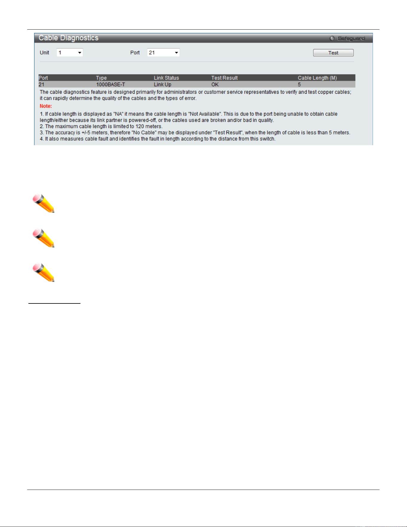
xStack® DGS-3420 Series Layer 2 Managed Stackable Gigabit Switch Web UI Reference Guide
413
Figure 10-22 Cable Diagnostics window
To view the cable diagnostics for a particular port, use the drop-down menu to choose the Unit ID and Port and click
Test The information will be displayed in this window.
NOTE: Cable diagnostic function limitations. Cable length detection is only supported on GE ports. Ports
must be linked up and running at 1000M speed. Cross-talk errors detection is not supported on FE
ports.
NOTE: The available cable diagnosis length is from 5 to 120 meters.
NOTE: The deviation of cable length detection is +/- 5M for GE ports.
Fault messages:
• Open - This pair is left open.
• Short - Two lines of this pair is shorted.
• CrossTalk - Lines of this pair is short with lines in other pairs.
• Unknown - The diagnosis does not obtain the cable status, please try again.
• NA - No cable was found, maybe it's because cable is out of diagnosis specification or the quality is too bad.
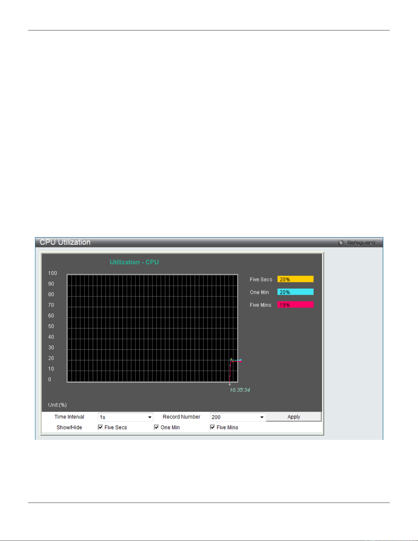
xStack® DGS-3420 Series Layer 2 Managed Stackable Gigabit Switch Web UI Reference Guide
414
Chapter 11 Monitoring
Utilization
Statistics
Mirror
sFlow
Ping
Trace Route
Peripheral
Utilization
CPU Utilization
This window is used to display the percentage of the CPU being used, expressed as an integer percentage and
calculated as a simple average by time interval.
To view this window, click Monitoring > Utilization > CPU Utilization as shown below:
Figure 11-1 CPU Utilization window
To view the CPU utilization by port, use the real-time graphic of the Switch and/or switch stack at the top of the web
page by simply clicking on a port. Click Apply to implement the configured settings. The window will automatically
refresh with new updated statistics.
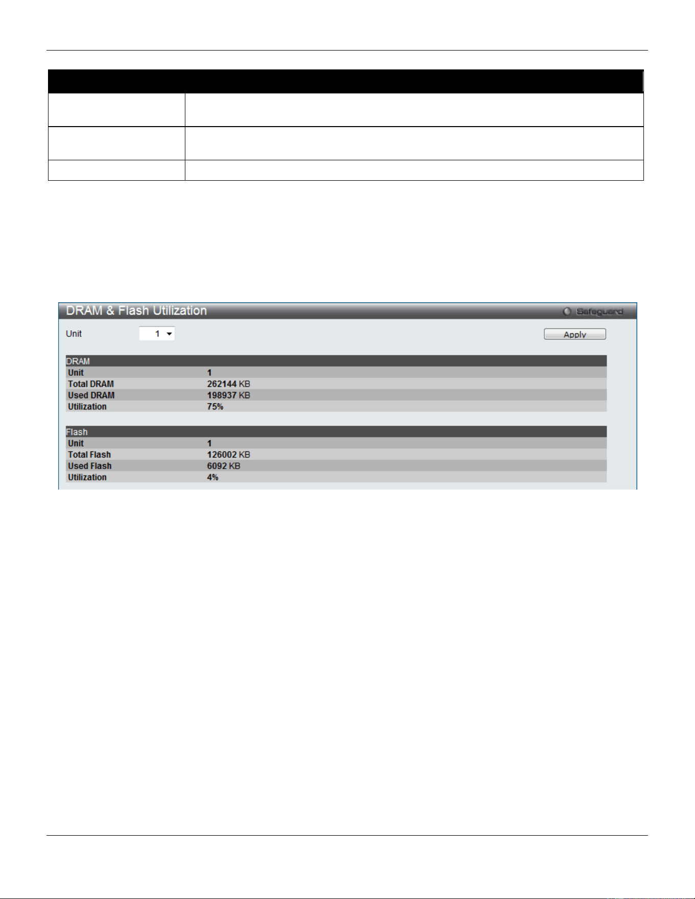
xStack® DGS-3420 Series Layer 2 Managed Stackable Gigabit Switch Web UI Reference Guide
415
The fields that can be configured are described below:
Parameter Description
Time Interval Select the desired setting between 1s and 60s, where "s" stands for seconds. The
default value is one second.
Record Number Select number of times the Switch will be polled between 20 and 200. The default value
is 200.
Show/Hide
Check whether or not to display Five Seconds, One Minute, and Five Minutes.
Click the Apply button to accept the changes made.
DRAM & Flash Utilization
This window is used to display information regarding the DRAM and Flash utilization.
To view this window, click Monitoring > Utilization > DRAM & Flash Utilization as shown below:
Figure 11-2 DRAM & Flash Utilization window
Port Utilization
This window is used to display the percentage of the total available bandwidth being used on the port.
To view this window, click Monitoring > Utilization > Port Utilization as shown below:
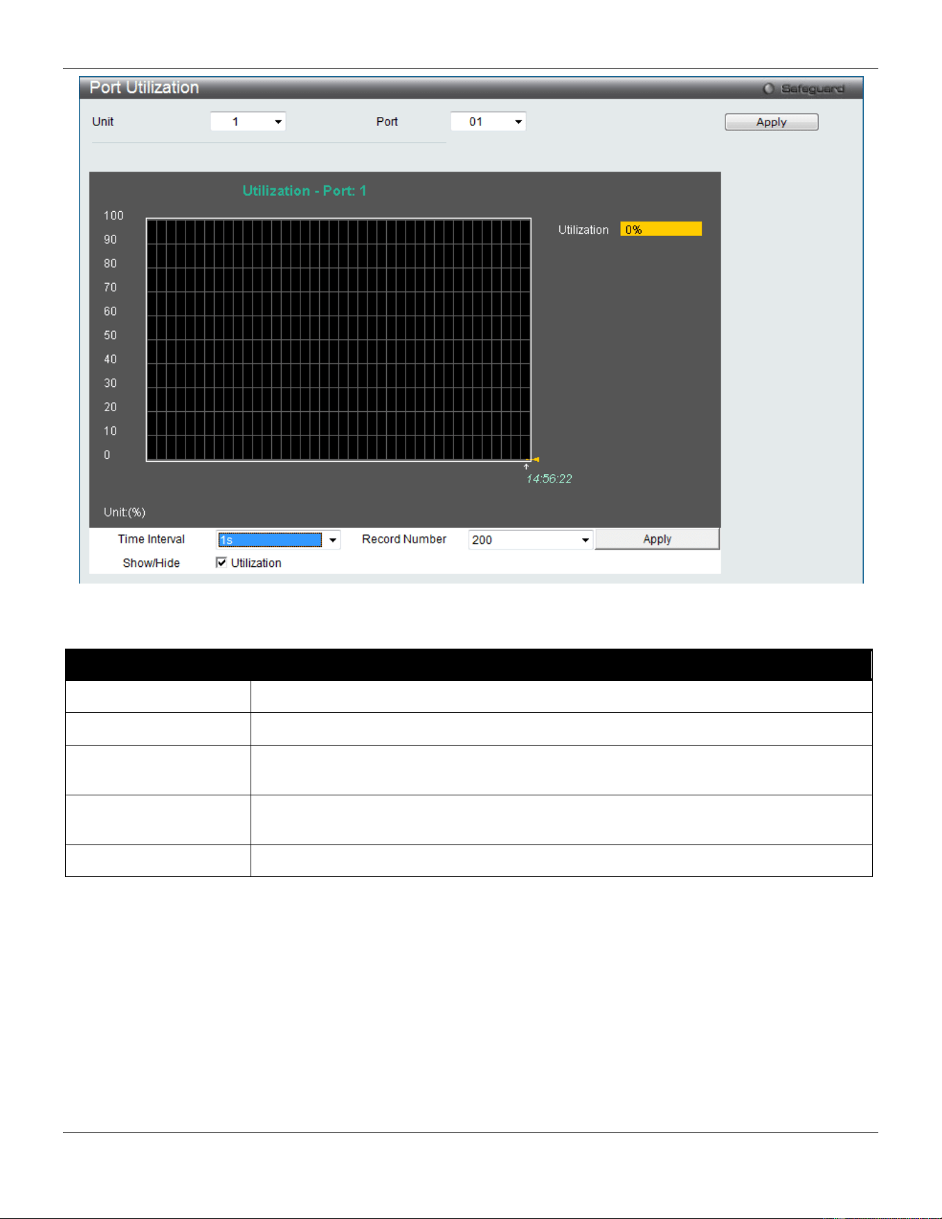
xStack® DGS-3420 Series Layer 2 Managed Stackable Gigabit Switch Web UI Reference Guide
416
Figure 11-3 Port Utilization window
The fields that can be configured are described below:
Parameter Description
Unit
Select the unit you wish to configure.
Port
Use the drop-down menu to choose the port that will display statistics.
Time Interval Select the desired setting between 1s and 60s, where "s" stands for seconds. The
default value is one second.
Record Number Select number of times the Switch will be polled between 20 and 200. The default value
is 200.
Show/Hide
Check whether or not to display Port Util.
Click the Apply button to accept the changes made for each individual section.
Statistics
Port Statistics
Packets
The Web manager allows various packet statistics to be viewed as either a line graph or a table. Six windows are
offered.
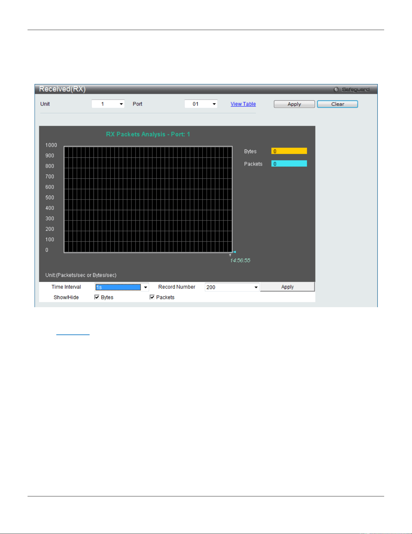
xStack® DGS-3420 Series Layer 2 Managed Stackable Gigabit Switch Web UI Reference Guide
417
Received (RX)
To select a port to view these statistics for, select the port by using the Port drop-down menu. The user may also use
the real-time graphic of the Switch at the top of the web page by simply clicking on a port.
To view this window, click Monitoring > Statistics > Port Statistics > Packets > Received (RX) as shown below:
Figure 11-4 Received (RX) window (for Bytes and Packets)
Click the View Table link to display the information in a table rather than a line graph.

xStack® DGS-3420 Series Layer 2 Managed Stackable Gigabit Switch Web UI Reference Guide
418
Figure 11-5 RX Packets Analysis Table window
The fields that can be configured are described below:
Parameter Description
Unit
Select the unit you wish to configure.
Port
Use the drop-down menu to choose the port that will display statistics.
Time Interval Select the desired setting between 1s and 60s, where "s" stands for seconds. The
default value is one second.
Record Number Select number of times the Switch will be polled between 20 and 200. The default value
is 200.
Bytes
Counts the number of bytes received on the port.
Packets
Counts the number of packets received on the port.
Unicast
Counts the total number of good packets that were received by a unicast address.
Multicast
Counts the total number of good packets that were received by a multicast address.
Broadcast
Counts the total number of good packets that were received by a broadcast address.
Show/Hide
Check whether to display Bytes and Packets.
Click the Apply button to accept the changes made for each individual section.
Click the Clear button to clear all statistics counters on this window.
Click the View Table link to display the information in a table rather than a line graph.
Click the View Graphic link to display the information in a line graph rather than a table.
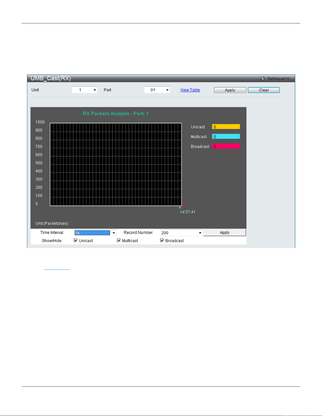
xStack® DGS-3420 Series Layer 2 Managed Stackable Gigabit Switch Web UI Reference Guide
419
UMB_Cast (RX)
To select a port to view these statistics for, select the port by using the Port drop-down menu. The user may also use
the real-time graphic of the Switch at the top of the web page by simply clicking on a port.
To view this window, click Monitoring > Statistics > Port Statistics > Packets > UMB_Cast (RX) as shown below:
Figure 11-6 UMB_cast (RX) window (for Unicast, Multicast, and Broadcast Packets)
Click the View Table link to display the information in a table rather than a line graph.
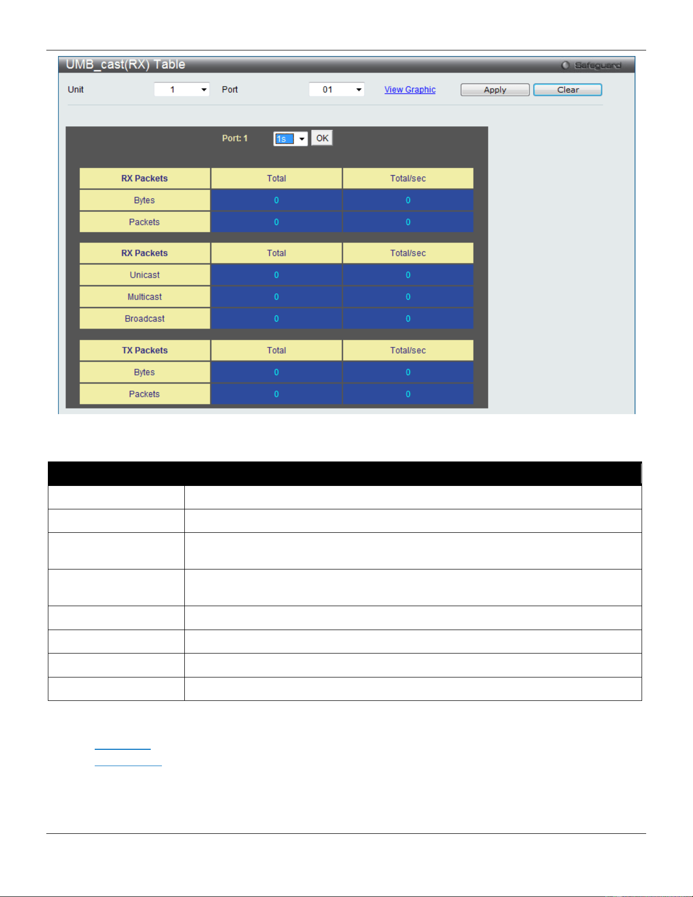
xStack® DGS-3420 Series Layer 2 Managed Stackable Gigabit Switch Web UI Reference Guide
420
Figure 11-7 RX Packets Analysis window (table for Unicast, Multicast, and Broadcast Packets)
The fields that can be configured are described below:
Parameter Description
Unit
Select the unit you wish to configure.
Port
Use the drop-down menu to choose the port that will display statistics.
Time Interval Select the desired setting between 1s and 60s, where "s" stands for seconds. The
default value is one second.
Record Number Select number of times the Switch will be polled between 20 and 200. The default value
is 200.
Unicast
Counts the total number of good packets that were received by a unicast address.
Multicast
Counts the total number of good packets that were received by a multicast address.
Broadcast
Counts the total number of good packets that were received by a broadcast address.
Show/Hide
Check whether or not to display Multicast, Broadcast, and Unicast Packets.
Click the Apply button to accept the changes made for each individual section.
Click the Clear button to clear all statistics counters on this window.
Click the View Table link to display the information in a table rather than a line graph.
Click the View Graphic link to display the information in a line graph rather than a table.
Transmitted (TX)
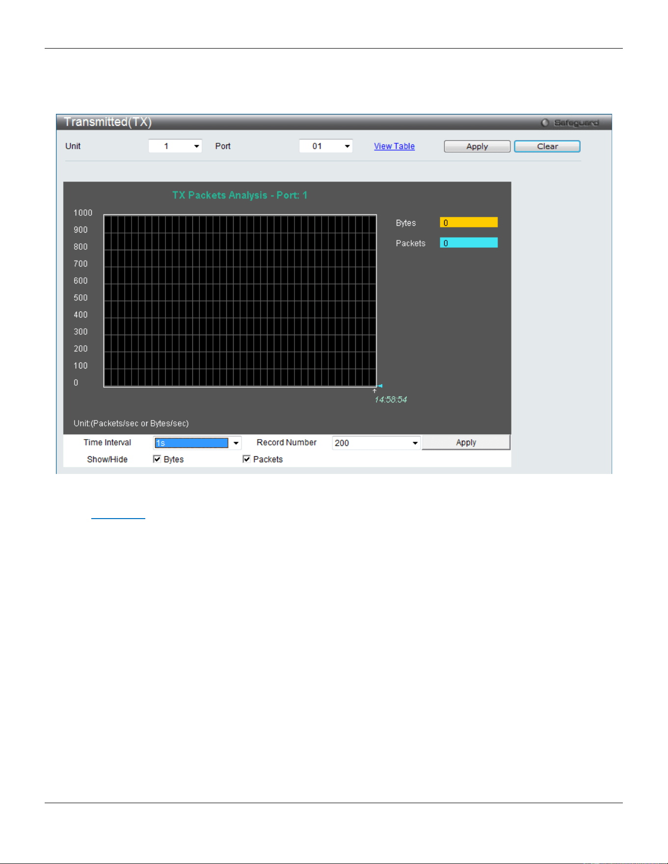
xStack® DGS-3420 Series Layer 2 Managed Stackable Gigabit Switch Web UI Reference Guide
421
To select a port to view these statistics for, select the port by using the Port drop-down menu. The user may also use
the real-time graphic of the Switch at the top of the web page by simply clicking on a port.
To view this window, click Monitoring > Statistics > Port Statistics > Packets > Transmitted (TX) as shown below:
Figure 11-8 Transmitted (TX) window (for Bytes and Packets)
Click the View Table link to display the information in a table rather than a line graph.

xStack® DGS-3420 Series Layer 2 Managed Stackable Gigabit Switch Web UI Reference Guide
422
Figure 11-9 TX Packets Analysis window (table for Bytes and Packets)
The fields that can be configured are described below:
Parameter Description
Unit
Select the unit you wish to configure.
Port
Use the drop-down menu to choose the port that will display statistics.
Time Interval Select the desired setting between 1s and 60s, where "s" stands for seconds. The
default value is one second.
Record Number Select number of times the Switch will be polled between 20 and 200. The default value
is 200.
Bytes
Counts the number of bytes successfully sent on the port.
Packets
Counts the number of packets successfully sent on the port.
Unicast
Counts the total number of good unicast packets.
Multicast
Counts the total number of good multicast packets.
Broadcast
Counts the total number of good broadcast packets.
Show/Hide
Check whether or not to display Bytes and Packets.
Click the Apply button to accept the changes made for each individual section.
Click the Clear button to clear all statistics counters on this window.
Click the View Table link to display the information in a table rather than a line graph.
Click the View Graphic link to display the information in a line graph rather than a table.
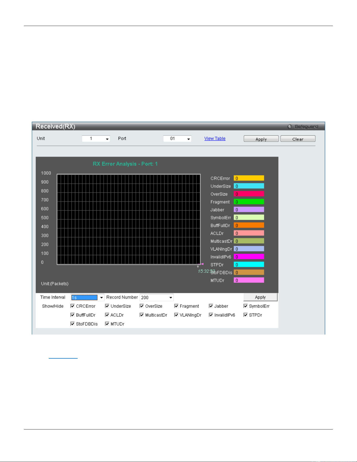
xStack® DGS-3420 Series Layer 2 Managed Stackable Gigabit Switch Web UI Reference Guide
423
Errors
The Web manager allows port error statistics compiled by the Switch's management agent to be viewed as either a line
graph or a table. Four windows are offered.
Received (RX)
To select a port to view these statistics for, select the port by using the Port drop-down menu. The user may also use
the real-time graphic of the Switch at the top of the web page by simply clicking on a port.
To view this window, click Monitoring > Statistics > Port Statistics > Errors > Received (RX) as shown below:
Figure 11-10 Received (RX) window (for errors)
Click the View Table link to display the information in a table rather than a line graph.
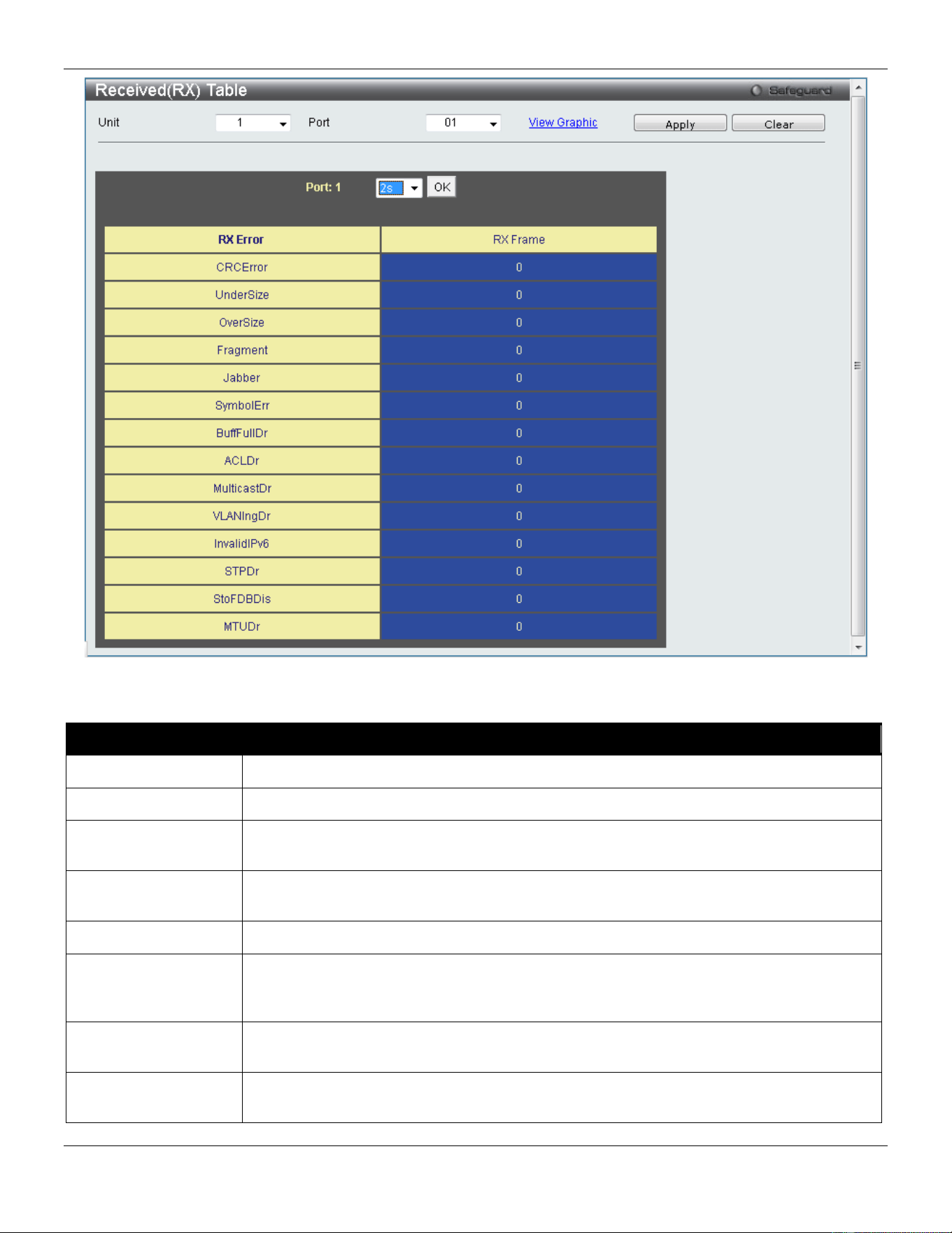
xStack® DGS-3420 Series Layer 2 Managed Stackable Gigabit Switch Web UI Reference Guide
424
Figure 11-11 RX Error Analysis window (table)
The fields that can be configured are described below:
Parameter Description
Unit
Select the unit you wish to configure.
Port
Use the drop-down menu to choose the port that will display statistics.
Time Interval Select the desired setting between 1s and 60s, where "s" stands for seconds. The default
value is one second.
Record Number Select number of times the Switch will be polled between 20 and 200. The default value is
200.
CRCError
Counts otherwise valid packets that did not end on a byte (octet) boundary.
UnderSize
The number of packets detected that are less than the minimum permitted packets size of
64 bytes and have a good CRC. Undersize packets usually indicate collision fragments, a
normal network occurrence.
OverSize
Counts valid packets received that were longer than 1518 octets and less than the
MAX_PKT_LEN. Internally, MAX_PKT_LEN is equal to 1536.
Fragment
The number of packets less than 64 bytes with either bad framing or an invalid CRC.
These are normally the result of collisions.

xStack® DGS-3420 Series Layer 2 Managed Stackable Gigabit Switch Web UI Reference Guide
425
Jabber
Counts invalid packets received that were longer than 1518 octets and less than the
MAX_PKT_LEN. Internally, MAX_PKT_LEN is equal to 1536.
SymbolErr
Counts the number of packets received that have errors received in the symbol on the
physical labor.
BuffFullDr
Buffer Full Drop - Incremented for each packet that is discarded while the input buffer is
full.
ACLDr
ACL Drop - Incremented for each packet that is denied by ACLs.
MulticastDr
Multicast Drop - Incremented for each multicast packet that is discarded.
VLANIngDr
VLAN Ingress Drop - Incremented for each packet that is discarded by VLAN ingress
checking.
InvalidIPv6
Invalid IPv6 - Increment counter for IPv6 Layer 3 discards.
STPDr
STP Drop - Increment counter for packets dropped when the ingress port is not in the
forwarding state.
StoFDBDis
Storm and FDB Discard - Increment counter for received policy discards.
MTUDr
MTU Drop - Receive MTU Check Error Frame Counter. Incremented for frames received,
which exceeds the MAXFR (Maximum Frame) in length and contains a valid or invalid
FCS.
Show/Hide
Check whether or not to display CRCError, UnderSize, OverSize, Fragment, Jabber,
Drop, and SymbolErr errors.
Click the Apply button to accept the changes made for each individual section.
Click the Clear button to clear all statistics counters on this window.
Click the View Table link to display the information in a table rather than a line graph.
Click the View Graphic link to display the information in a line graph rather than a table.
Transmitted (TX)
To select a port to view these statistics for, select the port by using the Port drop-down menu. The user may also use
the real-time graphic of the Switch at the top of the web page by simply clicking on a port.
To view this window, click Monitoring > Statistics > Port Statistics > Errors > Transmitted (TX) as shown below:
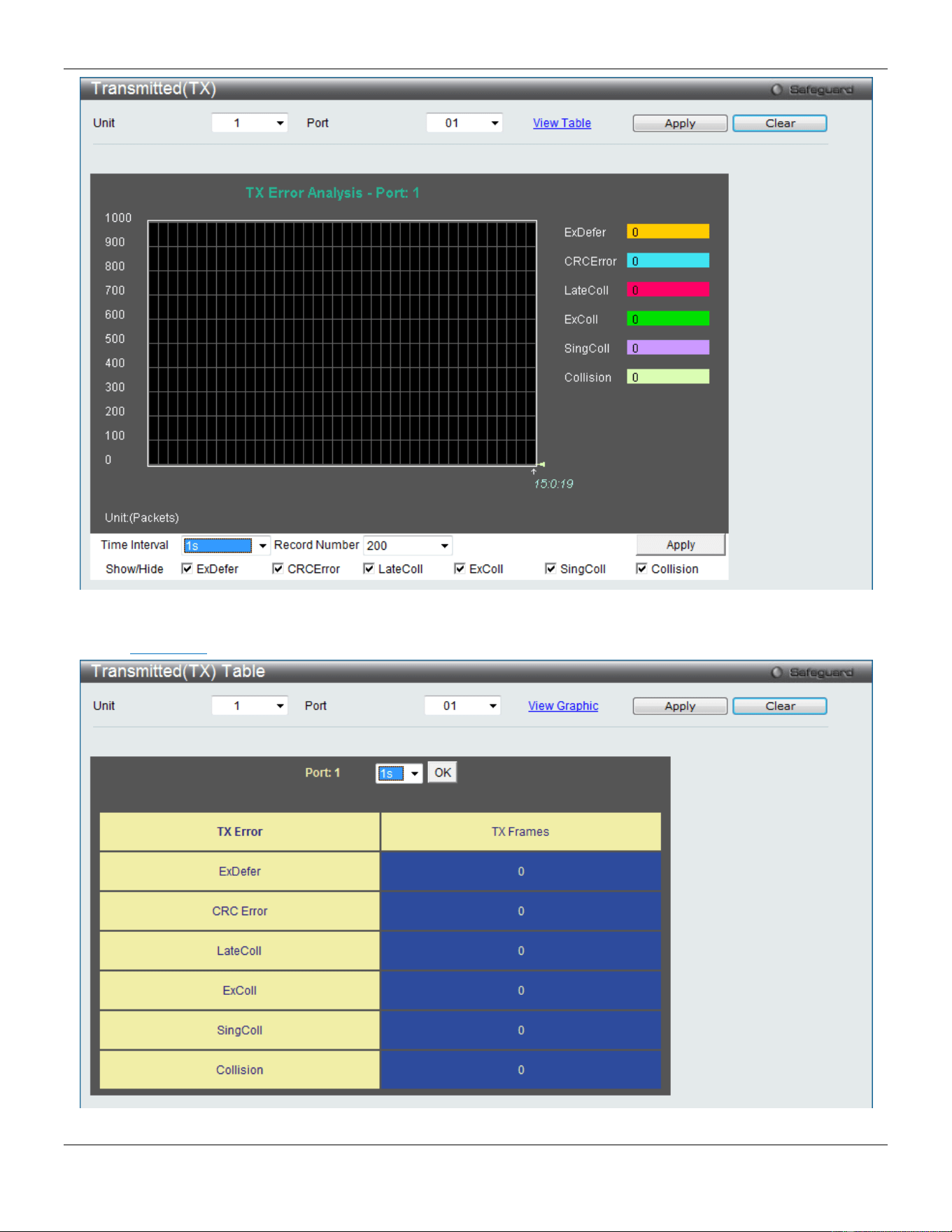
xStack® DGS-3420 Series Layer 2 Managed Stackable Gigabit Switch Web UI Reference Guide
426
Figure 11-12 Transmitted (TX) window (for errors)
Click the View Table link to display the information in a table rather than a line graph.
Figure 11-13 TX Error Analysis window (table)

xStack® DGS-3420 Series Layer 2 Managed Stackable Gigabit Switch Web UI Reference Guide
427
The fields that can be configured are described below:
Parameter Description
Unit
Select the unit you wish to configure.
Port
Use the drop-down menu to choose the port that will display statistics.
Time Interval Select the desired setting between 1s and 60s, where "s" stands for seconds. The default
value is one second.
Record Number Select number of times the Switch will be polled between 20 and 200. The default value is
200.
ExDefer
Counts the number of packets for which the first transmission attempt on a particular
interface was delayed because the medium was busy.
CRC Error
Counts otherwise valid packets that did not end on a byte (octet) boundary.
LateColl
Counts the number of times that a collision is detected later than 512 bit-times into the
transmission of a packet.
ExColl
Excessive Collisions. The number of packets for which transmission failed due to exces-
sive collisions.
SingColl
Single Collision Frames. The number of successfully transmitted packets for which
transmission is inhibited by more than one collision.
Collision
An estimate of the total number of collisions on this network segment.
Show/Hide
Check whether or not to display ExDefer, CRCError, LateColl, ExColl, SingColl, and
Collision errors.
Click the Apply button to accept the changes made for each individual section.
Click the Clear button to clear all statistics counters on this window.
Click the View Table link to display the information in a table rather than a line graph.
Click the View Graphic link to display the information in a line graph rather than a table.
Packet Size
Users can display packets received by the Switch, arranged in six groups and classed by size, as either a line graph or
a table. Two windows are offered. To select a port to view these statistics for, select the port by using the Port drop-
down menu. The user may also use the real-time graphic of the Switch at the top of the web page by simply clicking on
a port.
To view this window, click Monitoring > Statistics > Packet Size as shown below:
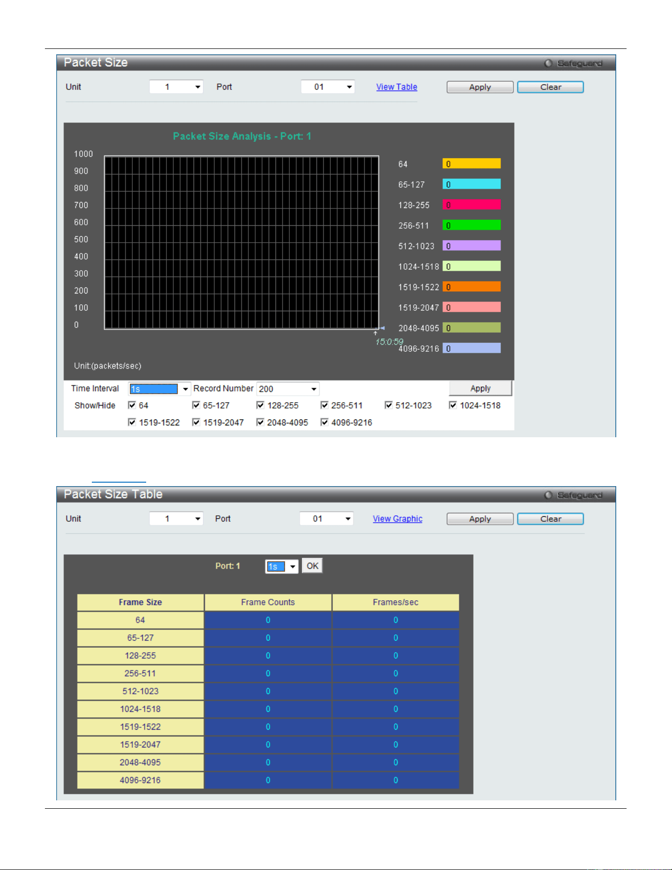
xStack® DGS-3420 Series Layer 2 Managed Stackable Gigabit Switch Web UI Reference Guide
428
Figure 11-14 Packet Size window
Click the View Table link to display the information in a table rather than a line graph.

xStack® DGS-3420 Series Layer 2 Managed Stackable Gigabit Switch Web UI Reference Guide
429
Figure 11-15 RX Size Analysis window (table)
The fields that can be configured are described below:
Parameter Description
Unit
Select the unit you wish to configure.
Port
Use the drop-down menu to choose the port that will display statistics.
Time Interval Select the desired setting between 1s and 60s, where "s" stands for seconds. The default
value is one second.
Record Number Select number of times the Switch will be polled between 20 and 200. The default value is
200.
64
The total number of packets (including bad packets) received that were 64 octets in length
(excluding framing bits but including FCS octets).
65-127
The total number of packets (including bad packets) received that were between 65 and
127 octets in length inclusive (excluding framing bits but including FCS octets).
128-255
The total number of packets (including bad packets) received that were between 128 and
255 octets in length inclusive (excluding framing bits but including FCS octets).
256-511
The total number of packets (including bad packets) received that were between 256 and
511 octets in length inclusive (excluding framing bits but including FCS octets).
512-1023
The total number of packets (including bad packets) received that were between 512 and
1023 octets in length inclusive (excluding framing bits but including FCS octets).
1024-1518
The total number of packets (including bad packets) received that were between 1024 and
1518 octets in length inclusive (excluding framing bits but including FCS octets).
1519-1522
The total number of packets (including bad packets) received that were between 1519 and
1522 octets in length inclusive (excluding framing bits but including FCS octets).
1519-2047
The total number of packets (including bad packets) received that were between 1519 and
2047 octets in length inclusive (excluding framing bits but including FCS octets).
2048-4095
The total number of packets (including bad packets) received that were between 2048 and
4095 octets in length inclusive (excluding framing bits but including FCS octets).
4096-9216
The total number of packets (including bad packets) received that were between 4096 and
9216 octets in length inclusive (excluding framing bits but including FCS octets).
Show/Hide
Check whether or not to display 64, 65-127, 128-255, 256-511, 512-1023, 1024-1518,
1519-1522, 1519-2047, 2048-1095 and 4096-9216 packets received.
Click the Apply button to accept the changes made for each individual section.
Click the Clear button to clear all statistics counters on this window.
Click the View Table link to display the information in a table rather than a line graph.
Click the View Graphic link to display the information in a line graph rather than a table.
Mirror
The Switch allows you to copy frames transmitted and received on a port and redirect the copies to another port. You
can attach a monitoring device to the mirroring port, such as a sniffer or an RMON probe, to view details about the
packets passing through the mirrored port. This is useful for network monitoring and troubleshooting purposes.
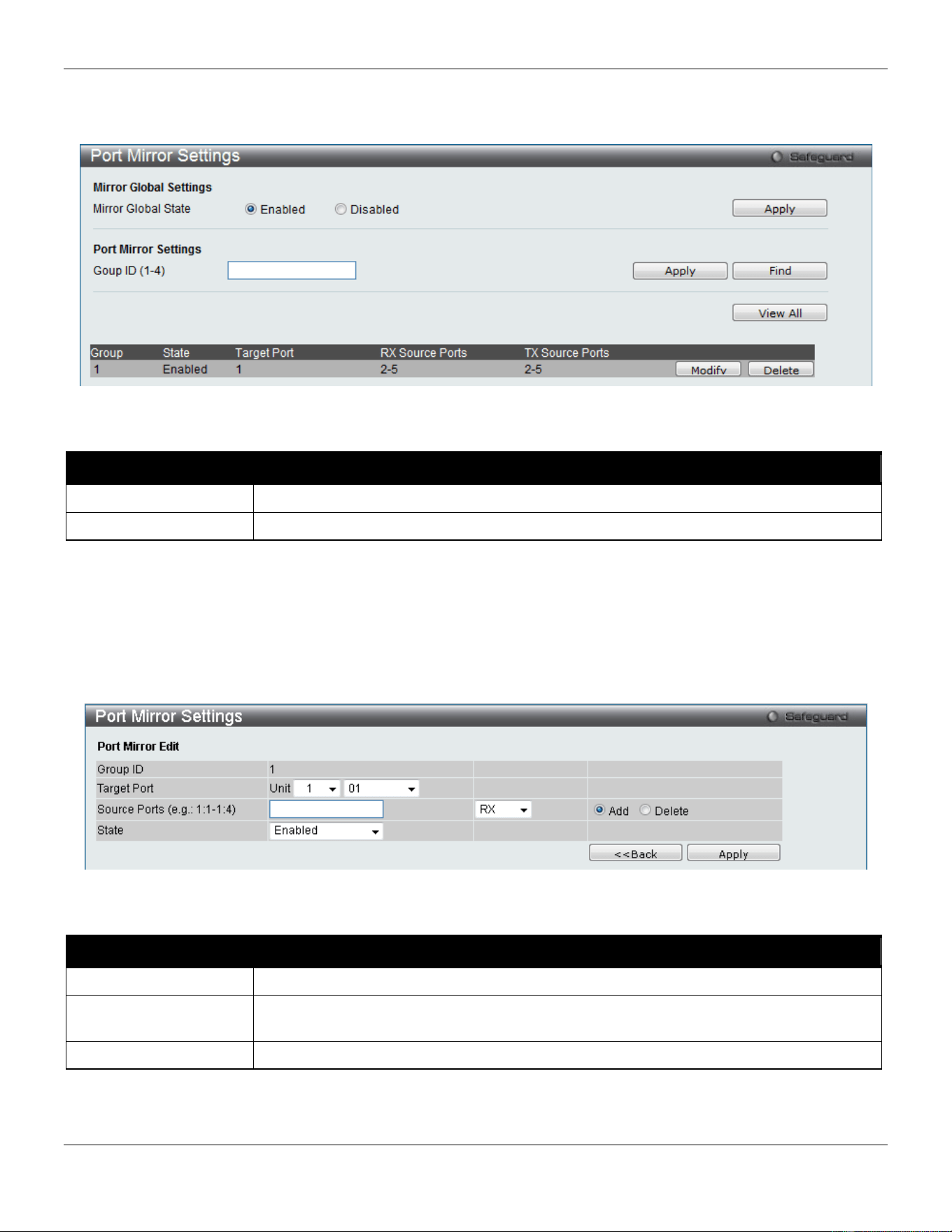
xStack® DGS-3420 Series Layer 2 Managed Stackable Gigabit Switch Web UI Reference Guide
430
Port Mirror Settings
To view this window, click Monitoring > Mirror > Port Mirror Settings as shown below:
Figure 11-16 Port Mirror Settings window
The fields that can be configured are described below:
Parameter Description
Mirror Global State
Click the radio buttons to enable or disable the Port Mirroring feature.
Group ID (1-4)
Enter a mirror group ID.
Click the Apply button to accept the changes made for each individual section.
Click the Find button to locate a specific entry based on the information entered.
Click the View All button to display all the existing entries.
Click the Modify button to re-configure the specific entry.
Click the Delete button to remove the specific entry.
Click the Modify button to see the following window.
Figure 11-17 Port Mirror Settings - Modify window
The fields that can be configured are described below:
Parameter Description
Target Port
Here the user can select the Unit and Target Port used for Port Mirroring.
Source Ports Enter the ports that will be mirrored. Select RX, TX or Both to specify in which direction
the packets will be monitored. Tick Add or Delete to add or delete source ports.
State
Enable or disable the mirror group function.
Click the Apply button to accept the changes made.
Click the <<Back button to discard the changes made and return to the previous page.
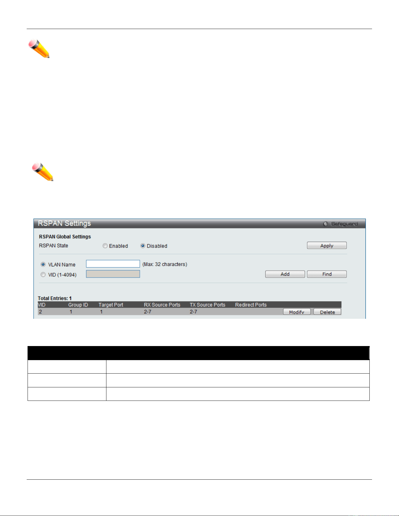
xStack® DGS-3420 Series Layer 2 Managed Stackable Gigabit Switch Web UI Reference Guide
431
NOTE: You cannot mirror a fast port onto a slower port. For example, if you try to mirror the traffic from a
100 Mbps port onto a 10 Mbps port, this can cause throughput problems. The port you are copying
frames from should always support an equal or lower speed than the port to which you are sending
the copies. Please note a target port and a source port cannot be the same port.
RSPAN Settings
This page controls the RSPAN function. The purpose of the RSPAN function is to mirror packets to a remote switch. A
packet travels from the switch where the monitored packet is received, passing through the intermediate switch, and
then to the switch where the sniffer is attached. The first switch is also named the source switch.
To make the RSPAN function work, the RSPAN VLAN source setting must be configured on the source switch. For the
intermediate and the last switch, the RSPAN VLAN redirect setting must be configured.
NOTE: RSPAN VLAN mirroring will only work when RSPAN is enabled (when one RSPAN VLAN has
been configured with a source port). The RSPAN redirect function will work when RSPAN is
enabled and at least one RSPAN VLAN has been configured with redirect ports.
To view this window, click Monitoring > Mirror > RSPAN Settings as shown below:
Figure 11-18 RSPAN Settings window
The fields that can be configured are described below:
Parameter Description
RSPAN State
Click the radio buttons to enable or disable the RSPAN feature.
VLAN Name
Create the RSPAN VLAN by VLAN name.
VID (1-4094)
Create the RSPAN VLAN by VLAN ID.
Click the Apply button to accept the changes made.
Click the Add button to add a new entry based on the information entered.
Click the Find button to locate a specific entry based on the information entered.
Click the Modify button to re-configure the specific entry.
Click the Delete button to remove the specific entry.
After clicking the Modify button, the following page will appear:
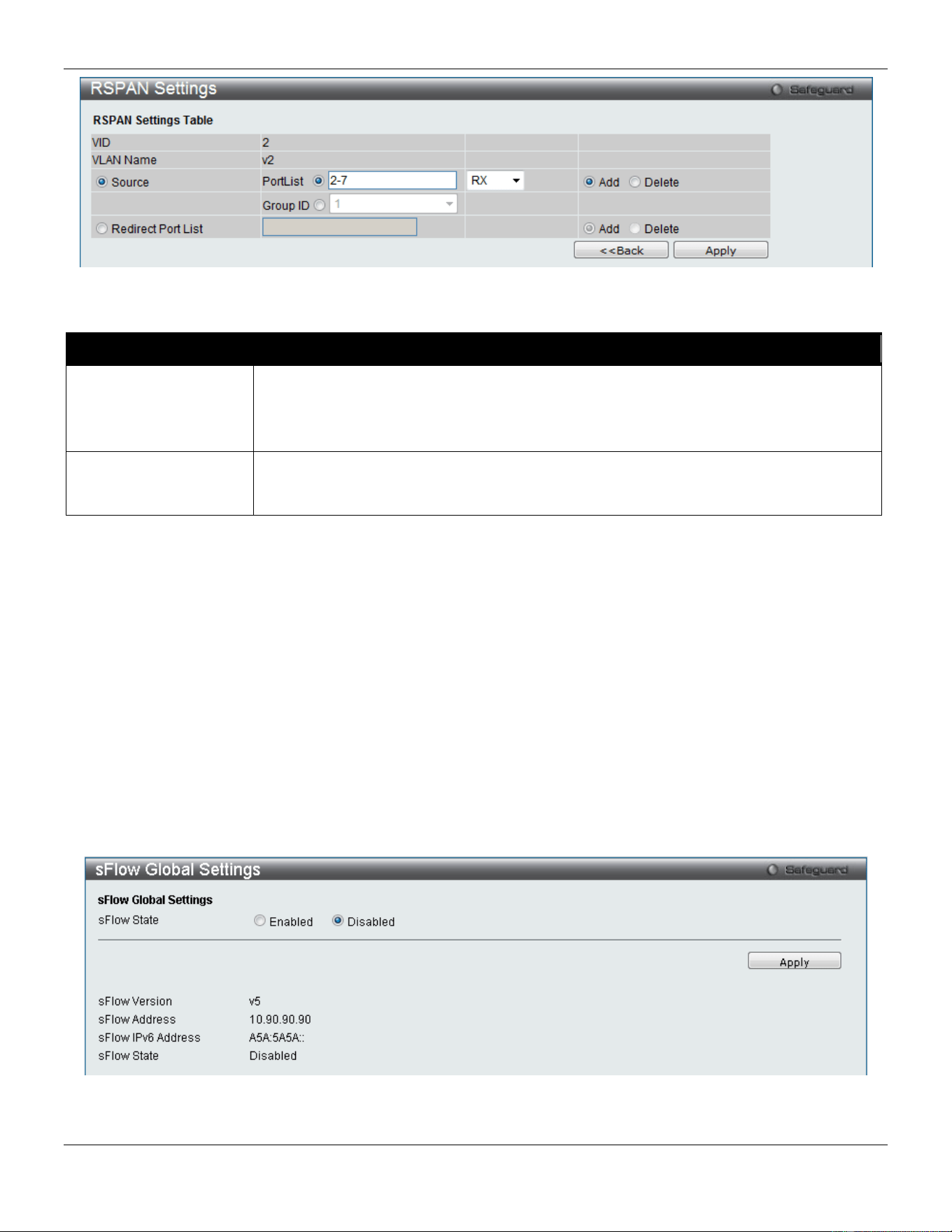
xStack® DGS-3420 Series Layer 2 Managed Stackable Gigabit Switch Web UI Reference Guide
432
Figure 11-19 RSPAN Settings – Modify window
The fields that can be configured are described below:
Parameter Description
Source Ports
If the ports are not specified by option, the source of RSPAN will come from the source
specified by the mirror command or the flow-based source specified by an ACL.
Select RX, TX or Both to specify in which direction the packets will be monitored. Click
Add or Delete to add or delete source ports.
Redirect Port List
Specify the output port list for the RSPAN VLAN packets. If the redirect port is a Link
Aggregation port, the Link Aggregation behavior will apply to the RSPAN packets. Click
Add or Delete to add or delete redirect ports.
Click the Apply button to accept the changes made.
Click the <<Back button to discard the changes made and return to the previous page.
sFlow
sFlow (RFC3176) is a technology for monitoring traffic in data networks containing switches and routers. The sFlow
monitoring system consists of an sFlow Agent (embedded in a switch or router or in a standalone probe) and a central
sFlow Collector. The architecture and sampling techniques used in the sFlow monitoring system were designed for
providing continuous site-wide (and enterprise-wide) traffic monitoring of high speed switched and routed networks.
sFlow Global Settings
This window is used to enable or disable the sFlow feature.
To view this window, click Monitoring > sFlow > sFlow Global Settings as shown below:
Figure 11-20 sFlow Global Settings window
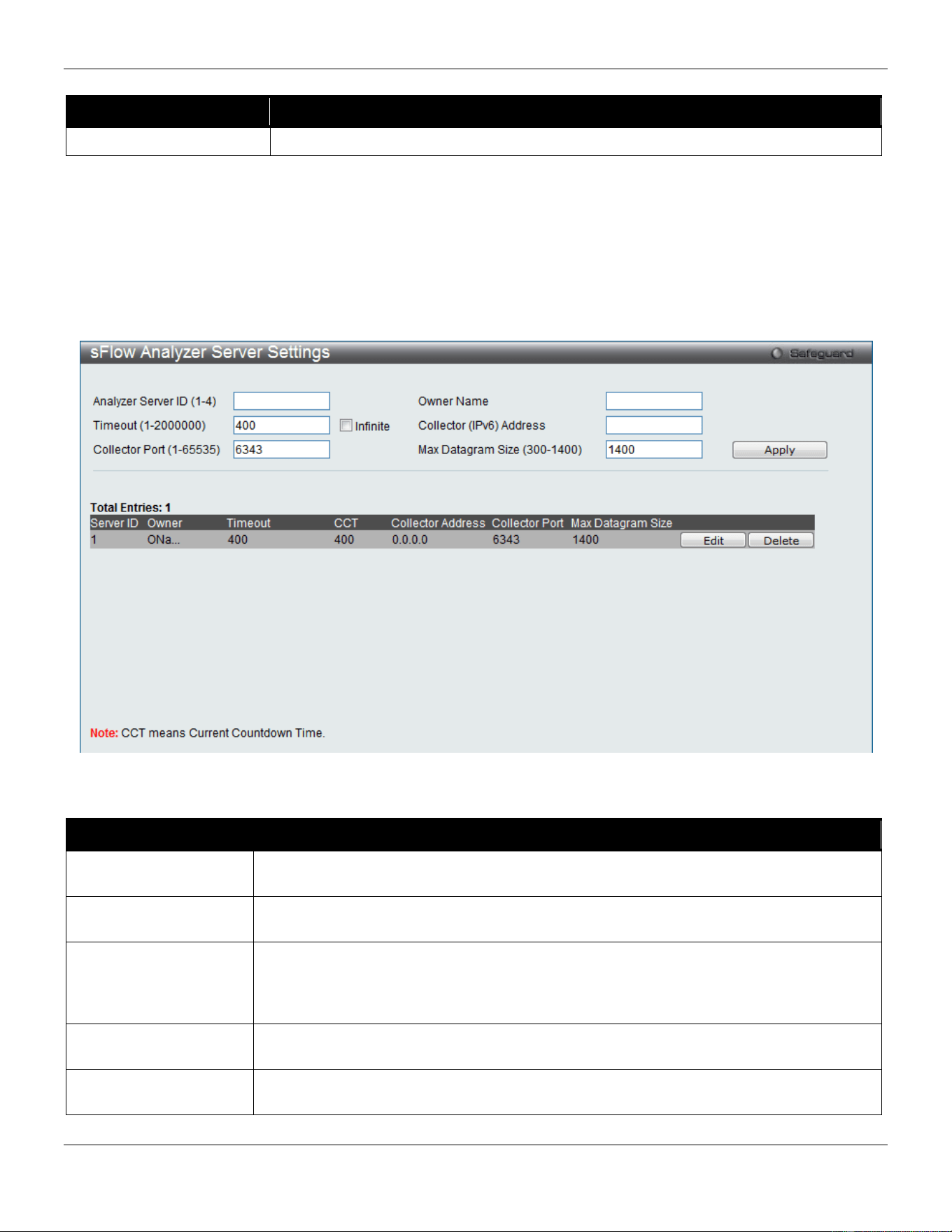
xStack® DGS-3420 Series Layer 2 Managed Stackable Gigabit Switch Web UI Reference Guide
433
The fields that can be configured are described below:
Parameter Description
sFlow State
Click the radio buttons to enable or disable the sFlow feature.
Click the Apply button to accept the changes made.
sFlow Analyzer Server Settings
The Switch can support 4 different Analyzer Servers at the same time and each sampler or poller can select a collector
to send the samples. We can send different samples from different samplers or pollers to different collectors.
To view this window, click Monitoring > sFlow > sFlow Analyzer Server Settings as shown below:
Figure 11-21 sFlow Analyzer Server Settings window
The fields that can be configured are described below:
Parameter Description
Analyzer Server ID (1-
4)
The analyzer server ID specifies the ID of a server analyzer where the packet will be
forwarded.
Owner Name
The entity making use of this sFlow analyzer server. When owner is set or modified, the
timeout value will become 400 automatically.
Timeout (1-2000000)
The length of time before the server times out. When the analyzer server times out, all of
the flow samplers and counter pollers associated with this analyzer server will be
deleted. If not specified, its default value is 400. Tick the Infinite check box to have
unlimited time.
Collector (IPv6)
Address
The IP address of the analyzer server. If not specified or set a 0 address, the entry will
be inactive.
Collector Port (1-
65535)
The destination UDP port for sending the sFlow datagrams. If not specified, the default
value is 6343.
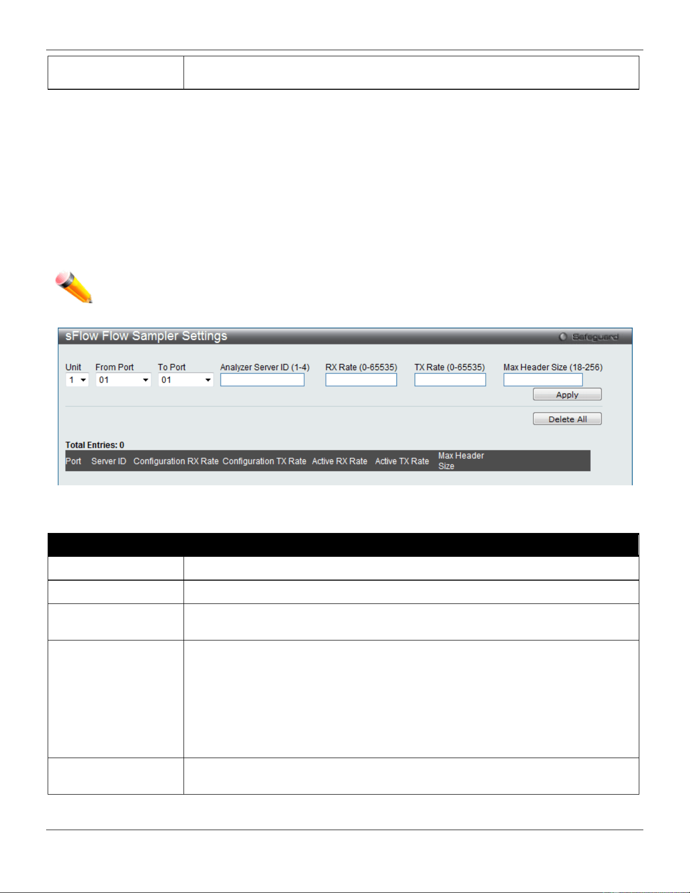
xStack® DGS-3420 Series Layer 2 Managed Stackable Gigabit Switch Web UI Reference Guide
434
Max Datagram Size
(300-1400)
The maximum number of data bytes that can be packed in a single sample datagram. If
not specified, the default value is 1400.
Click the Apply button to accept the changes made.
Click the Edit button to re-configure the specific entry.
Click the Delete button to remove the specific entry.
sFlow Flow Sampler Settings
On this page the user can configure the sFlow flow sampler parameters. By configuring the sampling function for a port,
a sample packet received by this port will be encapsulated and forwarded to the analyzer server at the specified
interval.
To view this window, click Monitoring > sFlow > sFlow Flow Sampler Settings as shown below:
NOTE: If the user wants the change the analyze server ID, he needs to delete the flow sampler and
creates a new one.
Figure 11-22 sFlow Flow Sampler Settings window
The fields that can be configured are described below:
Parameter Description
Unit
Select the unit you wish to configure.
From Port / To Port
Use the drop-down menus to specify the list of ports to be configured.
Analyzer Server ID
The analyzer server ID specifies the ID of a server analyzer where the packet will be
forwarded.
Rate The sampling rate for packet Rx sampling. The configured rate value multiplied by 256 is
the actual rate. For example, if the rate is 20, the actual rate 5120. One packet will be
sampled from every 5120 packets. If set to 0, the sampler is disabled. If the rate is not
specified, its default value is 0.
The sampling rate for packet Tx sampling. The configured rate value multiplied by 256 is
the actual rate. For example, if the rate is 20, the actual rate 5120. One packet will be
sampled from every 5120 packets. If set to 0, the sampler is disabled. If the rate is not
specified, its default value is 0.
MAX Header Size
The maximum number of leading bytes in the packet which has been sampled that will
be encapsulated and forwarded to the server. If not specified, the default value is 128.
Click the Apply button to accept the changes made.
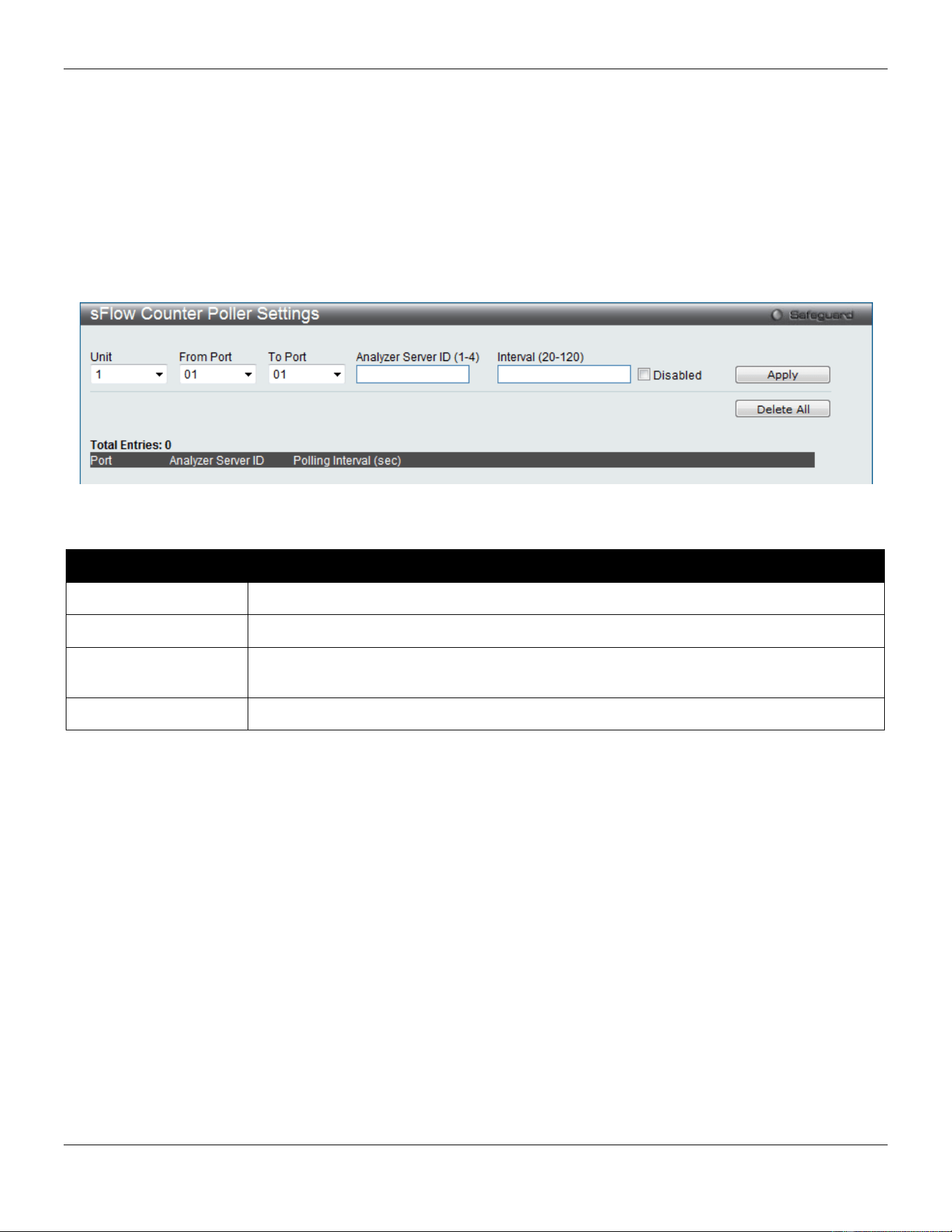
xStack® DGS-3420 Series Layer 2 Managed Stackable Gigabit Switch Web UI Reference Guide
435
Click the Delete All button to remove all the entries listed.
Click the Edit button to re-configure the specific entry.
Click the Delete button to remove the specific entry.
sFlow Counter Poller Settings
On this page the user can configure the sFlow counter poller parameters. If the user wants to change the analyzer
server ID, he needs to delete the counter poller and create a new one.
To view this window, click Monitoring > sFlow > sFlow Counter Poller Settings as shown below:
Figure 11-23 sFlow Counter Poller Settings
The fields that can be configured are described below:
Parameter Description
Unit
Select the unit you wish to configure.
From Port / To Port
Use the drop-down menus to specify the list of ports to be configured.
Analyzer Server ID
The analyzer server ID specifies the ID of a server analyzer where the packet will be
forwarded.
Interval
The maximum number of seconds between successive samples of the counters.
Click the Apply button to accept the changes made.
Click the Delete All button to remove all the entries listed.
Click the Edit button to re-configure the specific entry.
Click the Delete button to remove the specific entry.
Ping
Broadcast Ping Relay Settings
This window is used to enable or disable broadcast ping reply state, device will reply broadcast ping request.
To view this window, click Monitoring > Ping > Broadcast Ping Relay Settings as shown below:
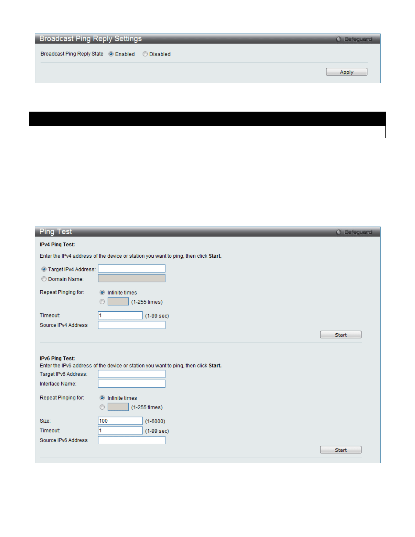
xStack® DGS-3420 Series Layer 2 Managed Stackable Gigabit Switch Web UI Reference Guide
436
Figure 11-24 Broadcast Ping Relay Settings window
The fields that can be configured are described below:
Parameter Description
Broadcast Ping Relay State
Click the radio buttons to enable or disable broadcast ping relay state.
Click the Apply button to accept the changes made.
Ping Test
Ping is a small program that sends ICMP Echo packets to the IP address you specify. The destination node then
responds to or “echoes” the packets sent from the Switch. This is very useful to verify connectivity between the Switch
and other nodes on the network.
To view this window, click Monitoring > Ping > Ping Test as shown below:
Figure 11-25 Ping Test window
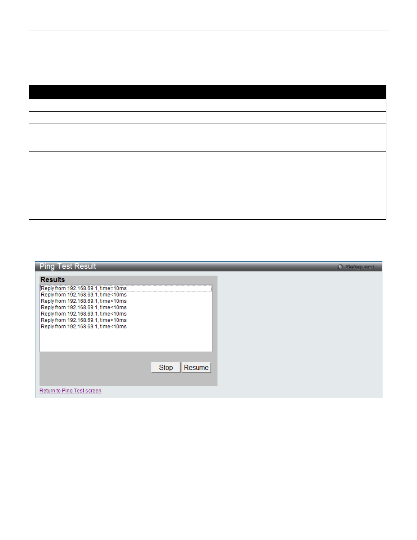
xStack® DGS-3420 Series Layer 2 Managed Stackable Gigabit Switch Web UI Reference Guide
437
The user may click the Infinite times radio button, in the Repeat Pinging for field, which will tell the ping program to
keep sending ICMP Echo packets to the specified IP address until the program is stopped. The user may opt to choose
a specific number of times to ping the Target IP Address by clicking its radio button and entering a number between 1
and 255.
The fields that can be configured are described below:
Parameter Description
Target IP Address
Click the radio button and enter an IP address to be pinged.
Domain Name
Click the radio button and enter the domain name of the host.
Repeat Pinging for
Enter the number of times desired to attempt to Ping either the IPv4 address or the IPv6
address configured in this window. Users may enter a number of times between 1 and
255.
Size
For IPv6 only, enter a value between 1 and 6000. The default is 100.
Timeout Select a timeout period between 1 and 99 seconds for this Ping message to reach its
destination. If the packet fails to find the IP address in this specified time, the Ping
packet will be dropped.
Source IP
the source IP/IPv6 address of the ping packets. If specifies source IP/IPv6 address, the
IP/IPv6 address will be used as the packets’ source IP address that ping send to remote
host.
Click the Start button to initiate the Ping Test.
After clicking the Start button, the following page will appear:
Figure 11-26 Ping Test Result window
Click the Stop button to halt the Ping Test.
Click the Resume button to resume the Ping Test.
Trace Route
The trace route page allows the user to trace a route between the switch and a given host on the network.
To view this window, click Monitoring > Trace Route as shown below:
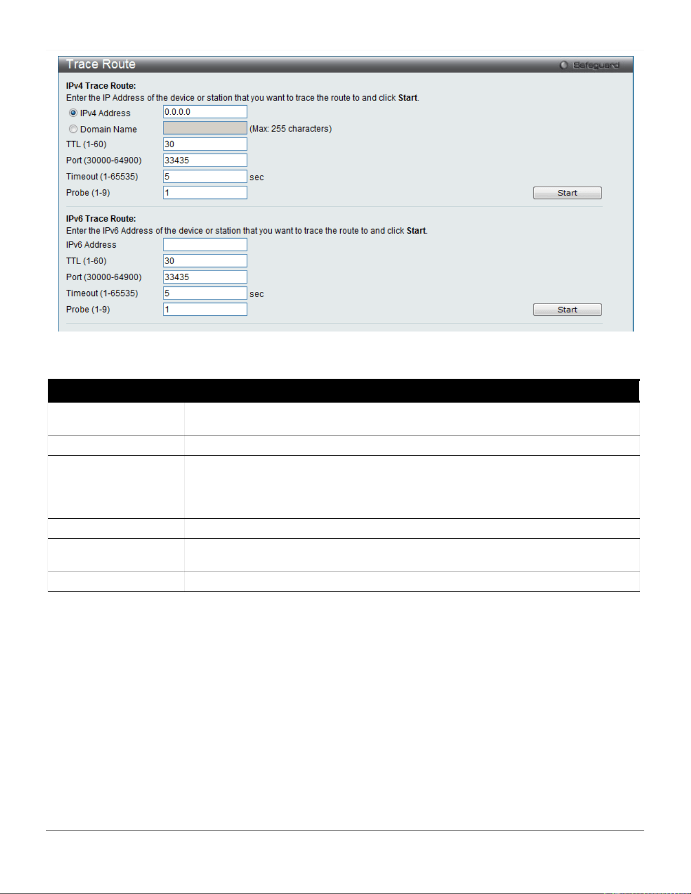
xStack® DGS-3420 Series Layer 2 Managed Stackable Gigabit Switch Web UI Reference Guide
438
Figure 11-27 Trace Route window
The fields that can be configured are described below:
Parameter Description
IPv4 Address / IPv6
Address
IP address of the destination station.
Domain Name
The domain name of the destination end station.
TTL (1-60)
The time to live value of the trace route request. This is the maximum number of routers
that a trace route packet can pass. The trace route option will cross while seeking the
network path between two devices.
The range for the TTL is 1 to 60 hops.
Port (30000-64900)
The port number. The value range is from 30000 to 64900.
Timeout (1-65535)
Defines the timeout period while waiting for a response from the remote device. A value
of 1 to 65535 seconds can be specified. The default is 5 seconds.
Probe (1-9)
The number of probing. The range is from 1 to 9. If unspecified, the default value is 1.
Click the Start button to initiate the Trace Route.
After clicking the Start button, the following page will appear:
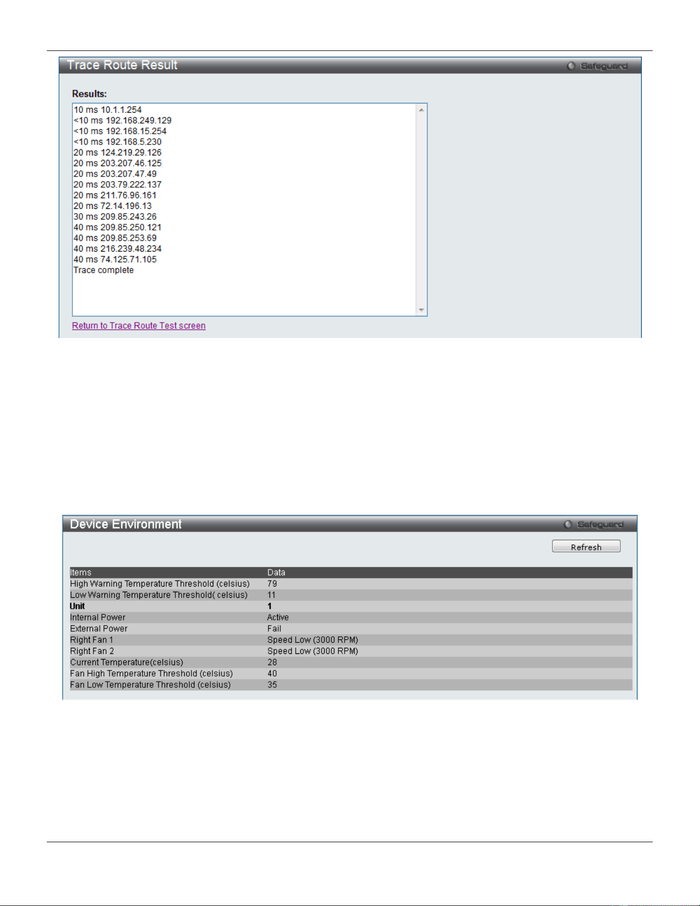
xStack® DGS-3420 Series Layer 2 Managed Stackable Gigabit Switch Web UI Reference Guide
439
Figure 11-28 Trace Route Result window
Peripheral
Device Environment
The device environment feature displays the Switch internal temperature status.
To view this window, click Monitoring > Peripheral > Device Environment as shown below:
Figure 11-29 Device Environment window
Click the Refresh button to refresh the display table.
External Alarm Settings
On this page, the user can configure the external alarm message for a channel.
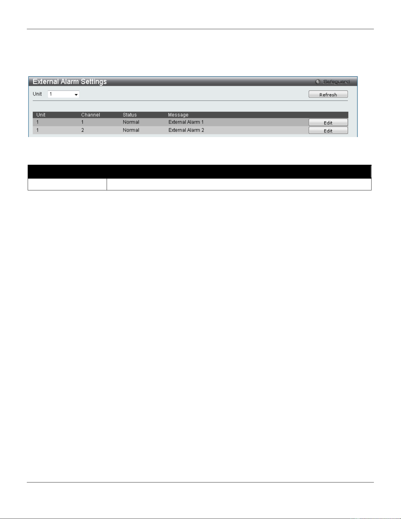
xStack® DGS-3420 Series Layer 2 Managed Stackable Gigabit Switch Web UI Reference Guide
440
The source for the alarm is located on the front panel of the Switch. They are monitored via the pre-defined connection
channels, with each channel representing a specific alarm event. This page also allows the user to define the alarm
event associated with each channel.
To view this window, click Monitoring > Peripheral > External Alarm Settings as shown below:
Figure 11-30 External Alarm Settings window
The fields that can be configured are described below:
Parameter Description
Unit
Specifies the unit ID to be displayed.
Click the Refresh button to refresh the display table.
Click the Edit button to re-configure the Message option for a specific entry.
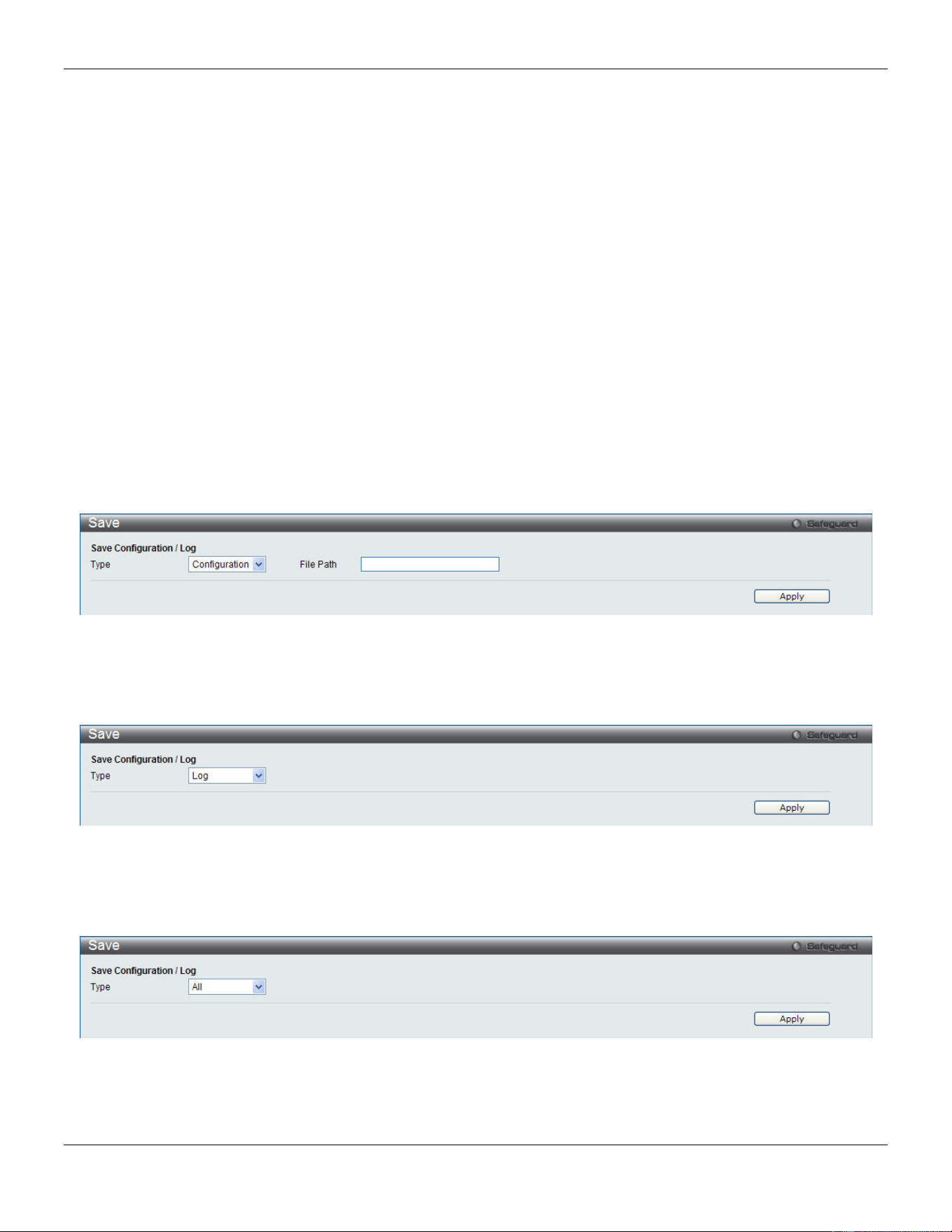
xStack® DGS-3420 Series Layer 2 Managed Stackable Gigabit Switch Web UI Reference Guide
441
Chapter 12 Save and Tools
Save Configuration / Log
Stacking Information
Download Firmware
Upload Firmware
Download Configuration
Upload Configuration
Upload Log File
Reset
Reboot System
Save Configuration / Log
To view this window, click Save > Save Configuration / Log, as shown below.
Save Configuration allows the user to backup the configuration of the switch to a folder on the computer. Select
Configuration from the Type drop-down menu and enter the File Path in the space provided and click Apply.
Figure 12-1 Save – Configuration window
Save Log allows the user to backup the log file of the switch. Select Log from the Type drop-down menu and click
Apply.
Figure 12-2 Save – Log window
Save All allows the user to permanently save changes made to the configuration. This option will allow the changes to
be kept after the switch has rebooted. Select All from the Type drop-down menu and click Apply.
Figure 12-3 Save – All window
Stacking Information
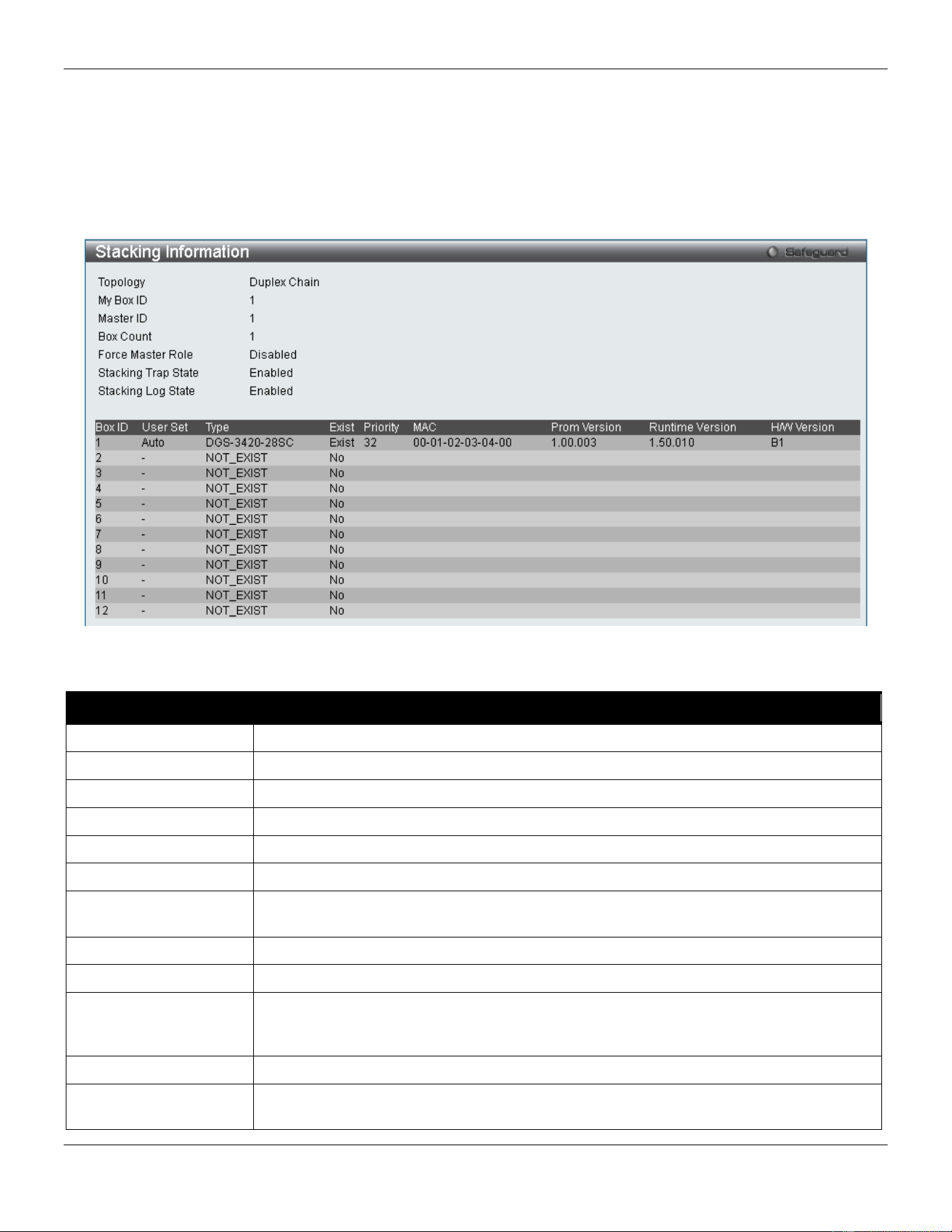
xStack® DGS-3420 Series Layer 2 Managed Stackable Gigabit Switch Web UI Reference Guide
442
To change a switch’s default stacking configuration (for example, the order in the stack), see System Configuration >
Stacking > Stacking Mode Settings window.
The number of switches in the switch stack (up to 12 total) are displayed next to the Tools drop-down menu. The icons
are in the same order as their respective Unit numbers, with the Unit 1 switch corresponding to the icon in the upper
left-most corner of the icon group.
When the switches are properly interconnected through their optional Stacking Modules, information about the
resulting switch stack is displayed under the Stacking Information link.
To view this window, click Tools > Stacking Information, as shown below.
Figure 12-4 Stacking Information window
The Stacking Information window displays the following information:
Parameter Description
Topology
Show the current topology employed using this Switch.
My Box ID
Display the Box ID of the Switch currently in use.
Master ID
Display the Unit ID number of the Primary Master of the Switch stack.
Box Count
Display the number of switches in the switch stack.
Force Master Role
Display force master role state
Box ID
Display the Switch’s order in the stack.
User Set
Box ID can be assigned automatically (Auto), or can be assigned statically. The default
is Auto.
Type
Display the model name of the corresponding switch in a stack.
Exist
Denote whether a switch does or does not exist in a stack.
Priority
Display the priority ID of the Switch. The lower the number, the higher the priority. The
box (switch) with the lowest priority number in the stack denotes the Primary Master
switch.
MAC
Display the MAC address of the corresponding switch in the switch stack.
Prom Version
Show the PROM in use for the Switch. This may be different from the values shown in
the illustration.
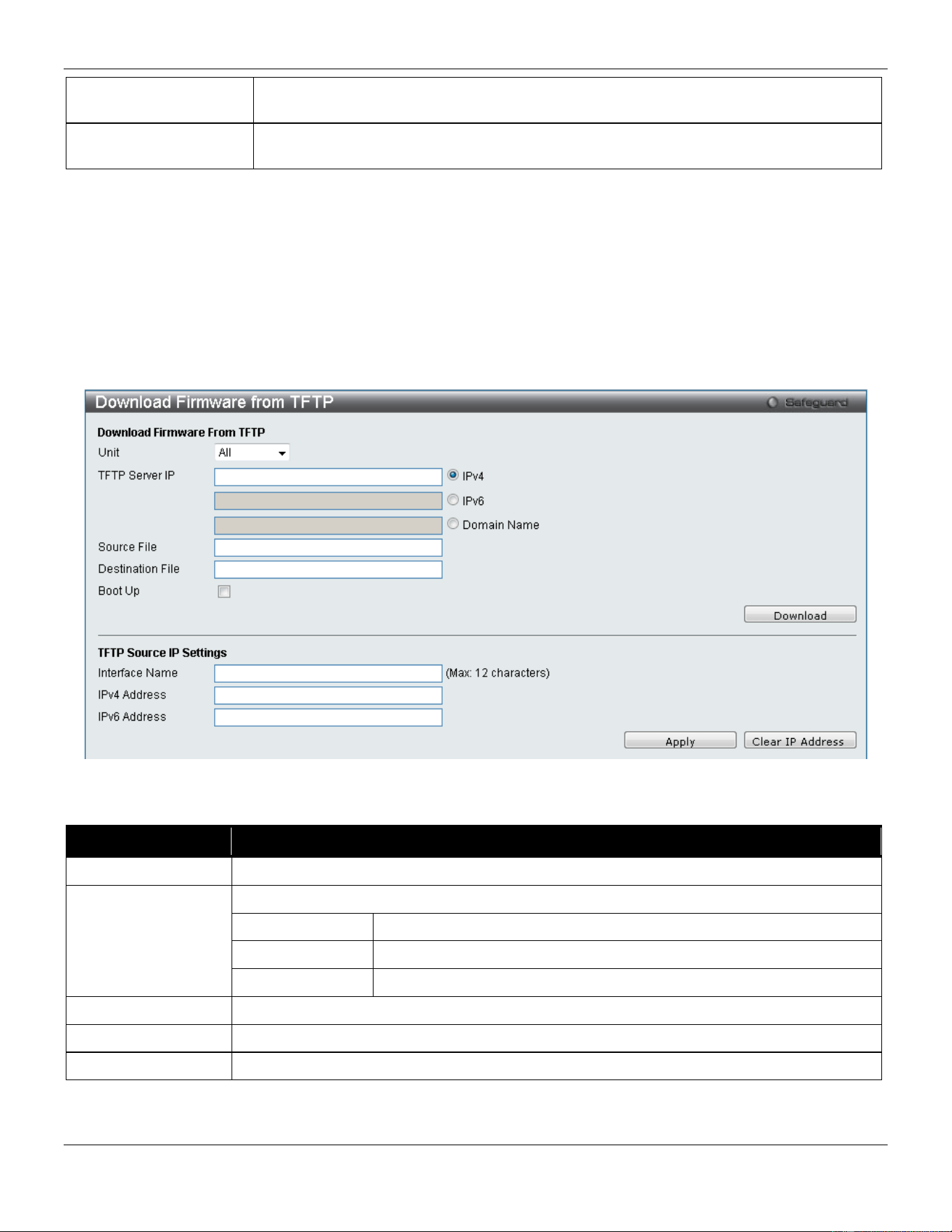
xStack® DGS-3420 Series Layer 2 Managed Stackable Gigabit Switch Web UI Reference Guide
443
Runtime Version
Show the firmware version in use for the Switch. This may be different from the values
shown in the illustrations.
H/W Version
Show the hardware version in use for the Switch. This may be different from the values
shown in the illustration.
Download Firmware
The following window is used to download firmware for the Switch.
Download Firmware from TFTP
This window allows the user to download firmware from a TFTP Server to the Switch and updates the switch.
Figure 12-5 Download Firmware from TFTP window
In the Download Firmware From TFTP section, the fields that can be configured are described below:
Parameter Description
Unit
Use the drop-down menu to select a unit for receiving the firmware. Select All for all units.
TFTP Server IP
Enter the TFTP server IP address used.
IPv4
Click the radio button to enter the TFTP server IP address used.
IPv6
Click the radio button to enter the TFTP server IPv6 address used.
Domain Name
Click the radio button to enter the domain name.
Source File
Enter the location and name of the Source File.
Destination File
Enter the location and name of the Destination File.
Boot Up
Tick the check box to set it as a boot up file.
Click Download to initiate the download.
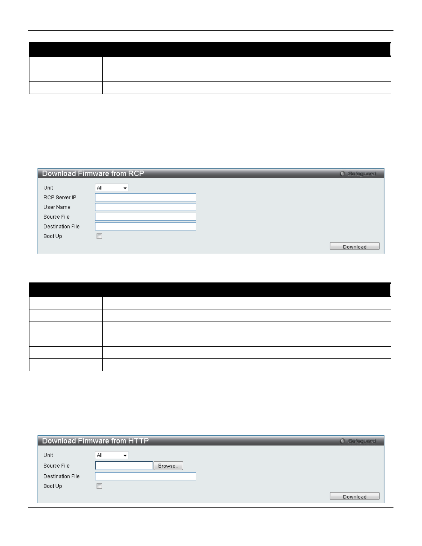
xStack® DGS-3420 Series Layer 2 Managed Stackable Gigabit Switch Web UI Reference Guide
444
In the TFTP Source IP Settings section, the fields that can be configured are described below:
Parameter Description
Interface Name
Enter the source interface name used here.
IPv4 Address
Enter the source IPv4 address used here.
IPv6 Address
Enter the source IPv6 address used here.
Click the Apply button to accept the changes made.
Click the Clear IP Address button to clear the IP addresses linked to the source IP interface.
Download Firmware from RCP
This window allows the user to download firmware from a RCP Server to the Switch and updates the switch.
Figure 12-6 Download Firmware from RCP window
The fields that can be configured are described below:
Parameter Description
Unit
Use the drop-down menu to select a unit for receiving the firmware. Select All for all units.
RCP Server IP
Enter the RCP server IP address used.
Source File
Enter the location and name of the Source File.
User Name
Enter the remote user name on the RCP server.
Destination File
Enter the location and name of the Destination File.
Boot Up
Tick the check box to set it as a boot up file.
Click Download to initiate the download.
Download Firmware from HTTP
This window allows the user to download firmware from a computer to the Switch and updates the switch.
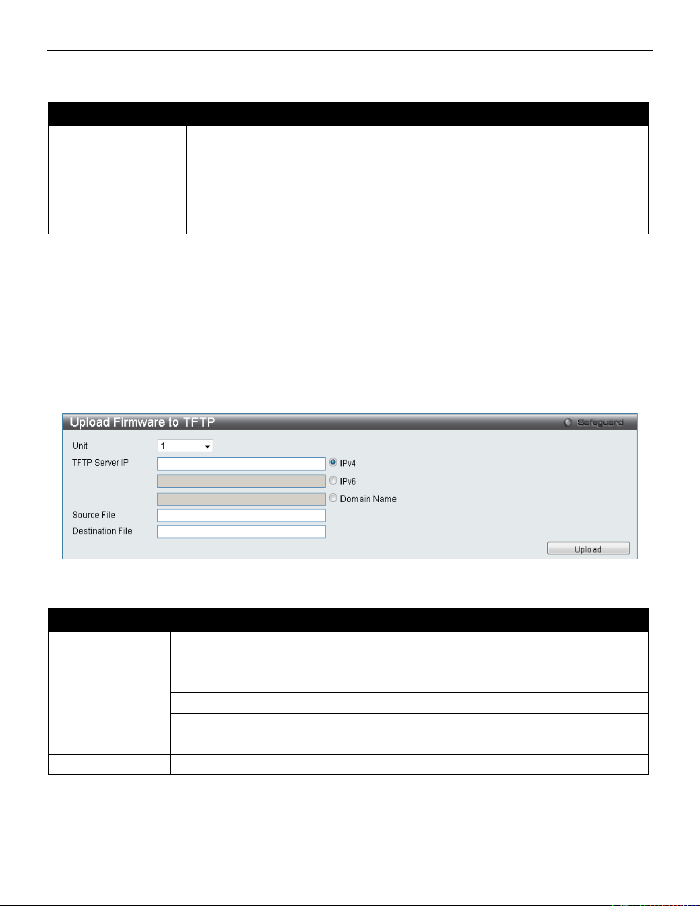
xStack® DGS-3420 Series Layer 2 Managed Stackable Gigabit Switch Web UI Reference Guide
445
Figure 12-7 Download Firmware from HTTP window
The fields that can be configured are described below:
Parameter Description
Unit Use the drop-down menu to select a unit for receiving the firmware. Select All for all
units.
Source File Enter the location and name of the Source File or click the Browse button to navigate to
the firmware file for the download.
Destination File
Enter the location and name of the Destination File.
Boot Up
Tick the check box to set it as a boot up file.
Click Download to initiate the download.
Upload Firmware
The following window is used to upload firmware from the Switch.
Upload Firmware to TFTP
This window allows the user to upload firmware from the Switch to a TFTP Server.
Figure 12-8 Upload Firmware to TFTP window
The fields that can be configured are described below:
Parameter Description
Unit
Use the drop-down menu to select a unit for uploading the firmware.
TFTP Server IP
Enter the TFTP server IP address used.
IPv4
Click the radio button to enter the TFTP server IP address used.
IPv6
Click the radio button to enter the TFTP server IPv6 address used.
Domain Name
Click the radio button to enter the domain name.
Destination File
Enter the location and name of the Destination File.
Source File
Enter the location and name of the Source File.
Click Upload to initiate the upload.
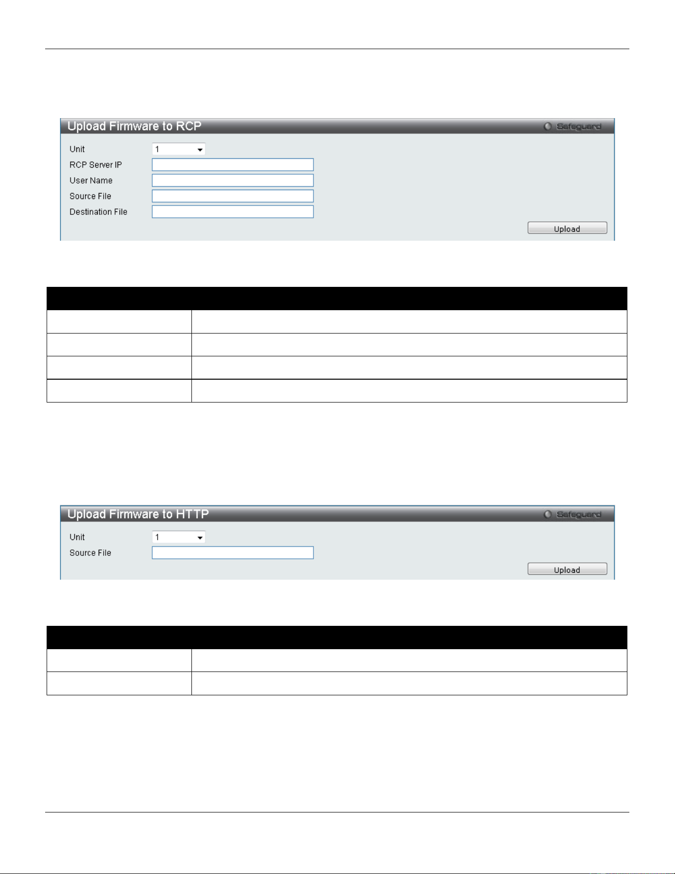
xStack® DGS-3420 Series Layer 2 Managed Stackable Gigabit Switch Web UI Reference Guide
446
Upload Firmware to RCP
This window allows the user to upload firmware from the Switch to a RCP Server.
Figure 12-9 Upload Firmware to RCP window
The fields that can be configured are described below:
Parameter Description
RCP Server IP
Enter the RCP Server IP Address used.
User Name
Enter the appropriate Username used.
Source File
Enter the location and name of the Source File.
Destination File
Enter the location and name of the Destination File.
Click Upload to initiate the upload.
Upload Firmware to HTTP
This window allows the user to upload firmware from the Switch to a HTTP Server.
Figure 12-10 Upload Firmware to FTP window
The fields that can be configured are described below:
Parameter Description
Unit
Use the drop-down menu to select a unit for uploading the firmware.
Source File
Enter the location and name of the Source File.
Click Upload to initiate the upload.
Download Configuration
The following window is used to download the configuration file for the Switch.
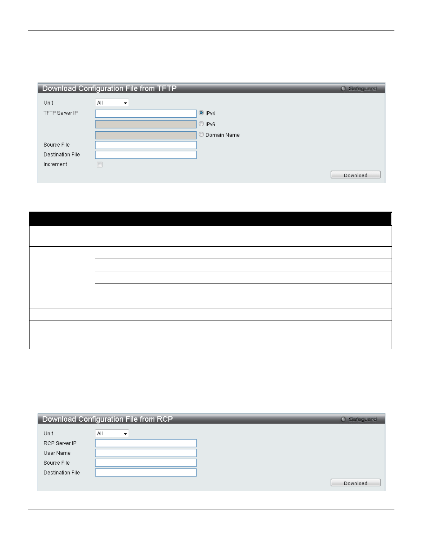
xStack® DGS-3420 Series Layer 2 Managed Stackable Gigabit Switch Web UI Reference Guide
447
Download Configuration from TFTP
This window allows the user to download the configuration file from a TFTP Server to the Switch and updates the
switch.
Figure 12-11 Download Configuration File from TFTP window
The fields that can be configured are described below:
Parameter Description
Unit Use the drop-down menu to select a unit for receiving the configuration file. Select All for all
units.
TFTP Server IP
Enter the TFTP server IP address used.
IPv4
Click the radio button to enter the TFTP server IP address used.
IPv6
Click the radio button to enter the TFTP server IPv6 address used.
Domain Name
Click the radio button to enter the domain name.
Source File
Enter the location and name of the Source File.
Destination File
Enter the location and name of the Destination File.
Increment
Tick the check box to keep the existing configuration before applying to the new configuration.
Deselect the check box to clear the existing configuration before applying to the new
configuration.
Click Download to initiate the download.
Download Configuration from RCP
This window allows the user to download the configuration file from a RCP Server to the Switch and updates the switch.
Figure 12-12 Download Configuration from RCP window
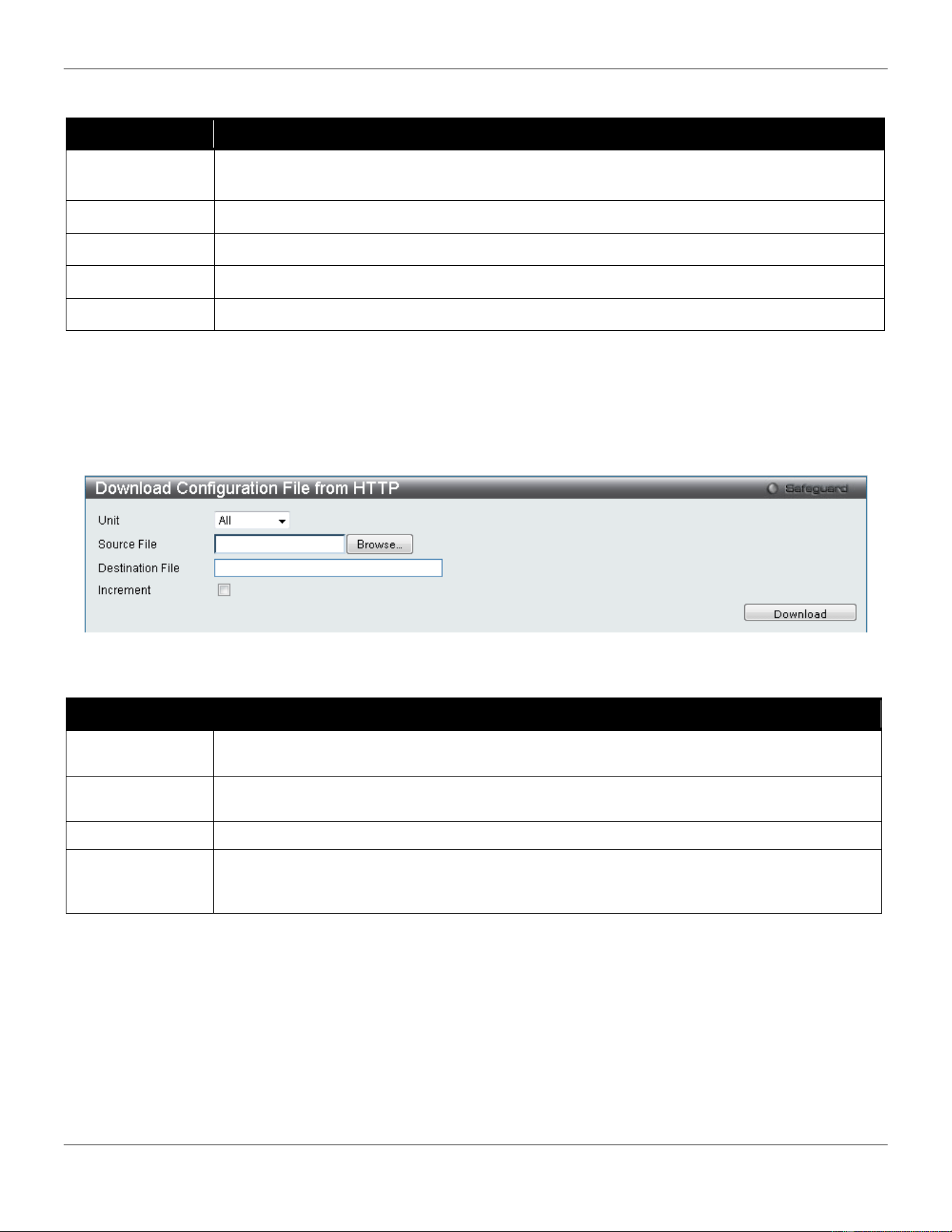
xStack® DGS-3420 Series Layer 2 Managed Stackable Gigabit Switch Web UI Reference Guide
448
The fields that can be configured are described below:
Parameter Description
Unit Use the drop-down menu to select a unit for receiving the configuration file. Select All for all
units.
RCP Server IP
Enter the RCP Server IP Address used.
User Name
Enter the appropriate Username used.
Source File
Enter the location and name of the Source File.
Destination File
Enter the location and name of the Destination File.
Click Download to initiate the download.
Download Configuration from HTTP
This window allows the user to download the configuration file from a computer to the Switch and updates the switch.
Figure 12-13 Download Configuration File from HTTP window
The fields that can be configured are described below:
Parameter Description
Unit Use the drop-down menu to select a unit for receiving the configuration file. Select All for all
units.
Source File Enter the location and name of the Source File, or click the Browse button to navigate to the
configuration file for the download.
Destination File
Enter the location and name of the Destination File.
Increment
Tick the check box to keep the existing configuration before applying to the new configuration.
Deselect the check box to clear the existing configuration before applying to the new
configuration.
Click Download to initiate the download.
Upload Configuration
The following window is used to upload the configuration file from the Switch.
Upload Configuration to TFTP
This window allows the user to upload the configuration file from the Switch to a TFTP Server.
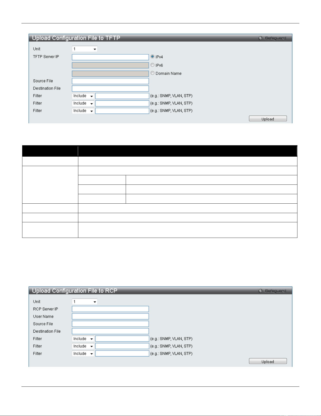
xStack® DGS-3420 Series Layer 2 Managed Stackable Gigabit Switch Web UI Reference Guide
449
Figure 12-14 Upload Configuration File to TFTP window
The fields that can be configured are described below:
Parameter Description
Unit
Use the drop-down menu to select a unit for uploading the configuration file.
TFTP Server IP
Enter the TFTP server IP address used.
IPv4
Click the radio button to enter the TFTP server IP address used.
IPv6
Click the radio button to enter the TFTP server IPv6 address used.
Domain Name
Click the radio button to enter the domain name.
Source File
Enter the location and name of the Source File.
Destination File
Enter the location and name of the Destination File.
Filter Use the drop-down menu to Include, Exclude or Begin a filter like SNMP, VLAN or STP.
Select the appropriate Filter action and enter the service name in the space provided.
Click Upload to initiate the upload.
Upload Configuration to RCP
This window allows the user to upload the configuration file from the Switch to a RCP Server.
Figure 12-15 Upload Configuration to RCP window
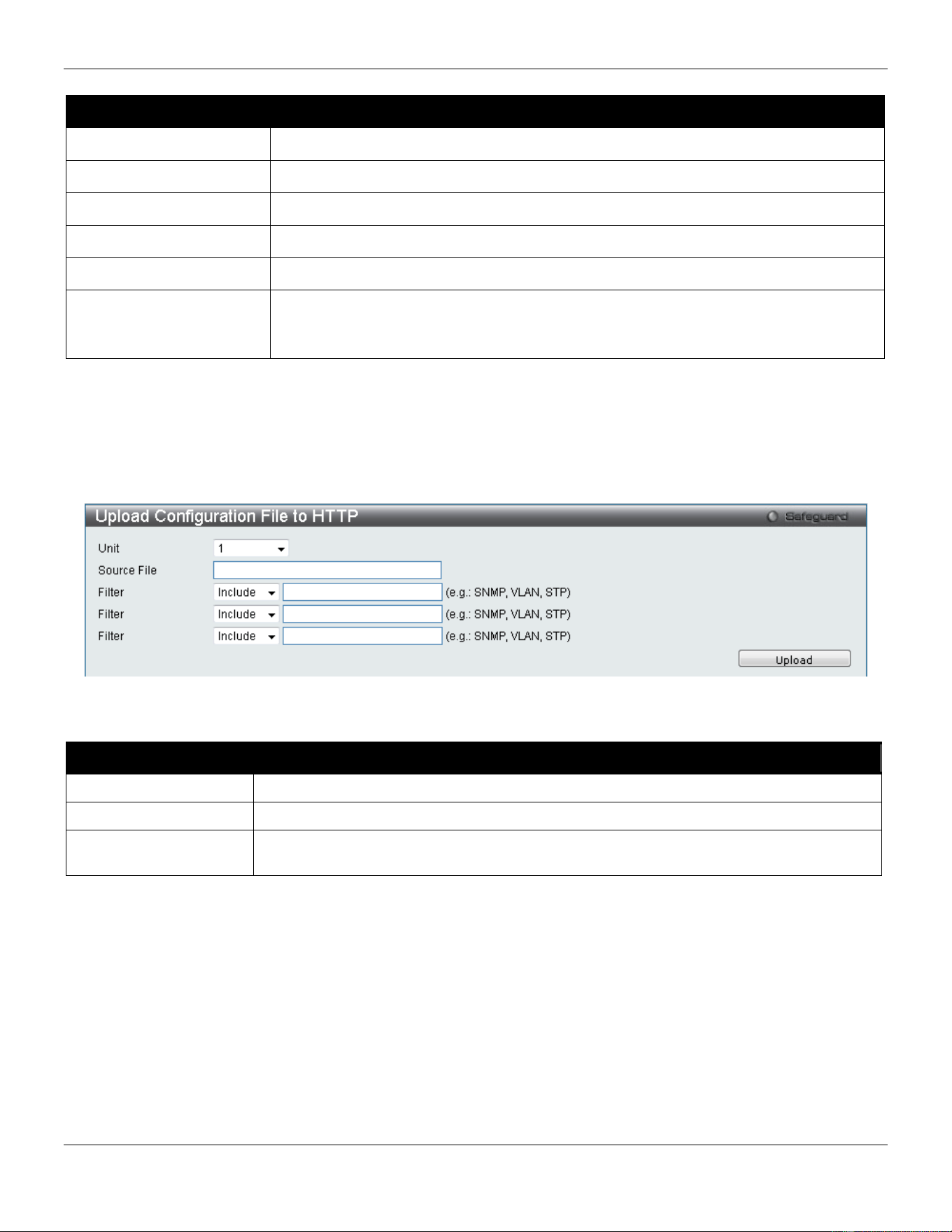
xStack® DGS-3420 Series Layer 2 Managed Stackable Gigabit Switch Web UI Reference Guide
450
The fields that can be configured are described below:
Parameter Description
Unit
Use the drop-down menu to select a unit for uploading the configuration file.
RCP Server IP
Enter the RCP Server IP Address used.
User Name
Enter the appropriate Username used.
Source File
Enter the location and name of the Source File.
Destination File
Enter the location and name of the Destination File.
Filter Use the drop-down menu to Include, Exclude or Begin a filter like SNMP, VLAN or
STP. Select the appropriate Filter action and enter the service name in the space
provided.
Click Upload to initiate the upload.
Upload Configuration to HTTP
This window allows the user to upload the configuration file from the Switch to a computer.
Figure 12-16 Upload Configuration File to HTTP window
The fields that can be configured are described below:
Parameter Description
Unit
Use the drop-down menu to select a unit for uploading the configuration file.
Source File
Enter the location and name of the Source File.
Filter Use the drop-down menu to Include, Exclude or Begin a filter like SNMP, VLAN or STP.
Select the appropriate Filter action and enter the service name in the space provided.
Click Upload to initiate the upload.
Upload Log File
The following window is used to upload the log file from the Switch.
Upload Log to TFTP
This window allows the user to upload the log file from the Switch to a TFTP Server.
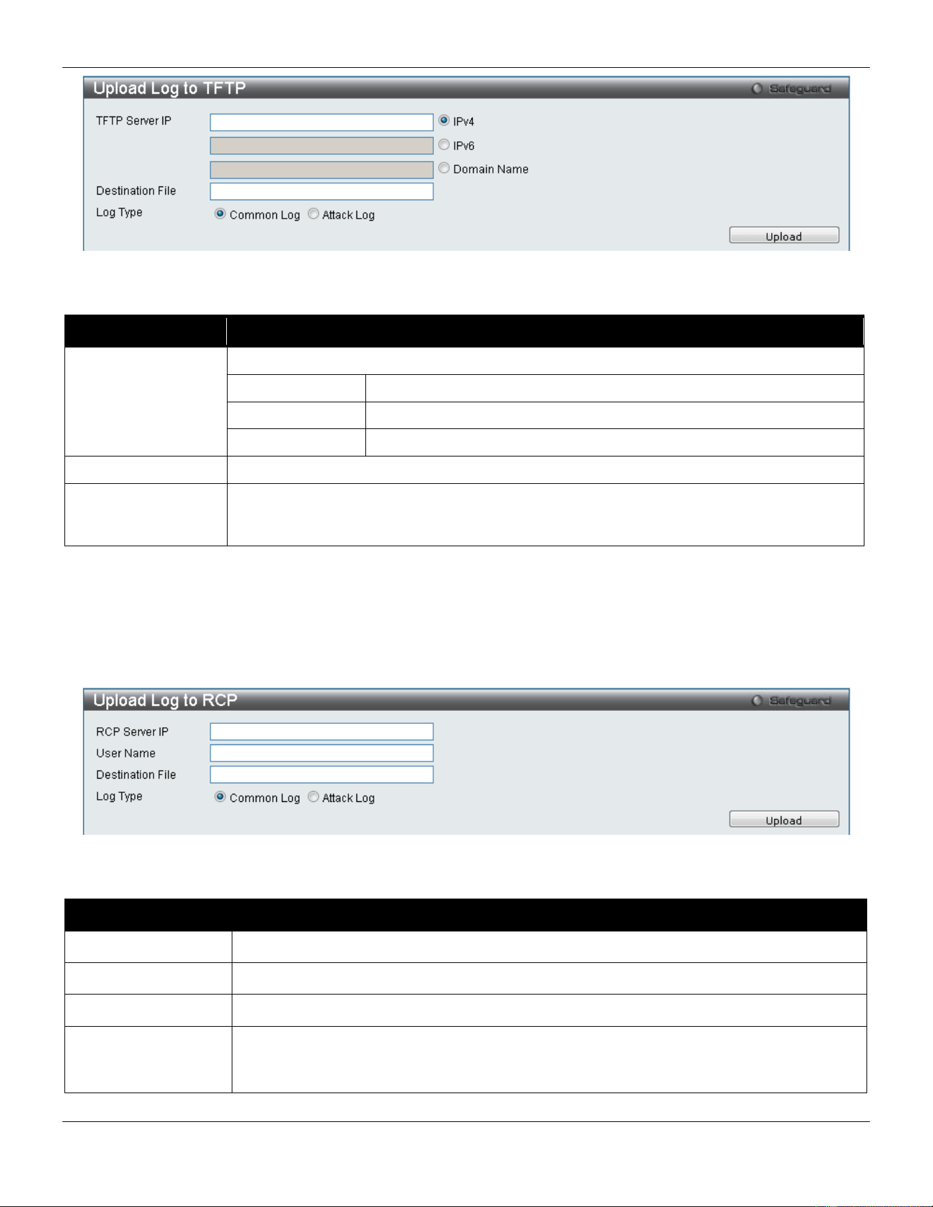
xStack® DGS-3420 Series Layer 2 Managed Stackable Gigabit Switch Web UI Reference Guide
451
Figure 12-17 Upload Log – TFTP window
The fields that can be configured are described below:
Parameter Description
TFTP Server IP
Enter the TFTP server IP address used.
IPv4
Click the radio button to enter the TFTP server IP address used.
IPv6
Click the radio button to enter the TFTP server IPv6 address used.
Domain Name
Click the radio button to enter the domain name.
Destination File
Enter the location and name of the Destination File.
Log Type Select the type of log to be transferred. Selecting the Common Log option here will upload
the common log entries. Selecting the Attack Log option here will upload the log
concerning attacks.
Click Upload to initiate the upload.
Upload Log to RCP
This window allows the user to upload the log file from the Switch to a RCP Server.
Figure 12-18 Upload Log to RCP window
The fields that can be configured are described below:
Parameter Description
RCP Server IP
Enter the RCP Server IP Address used.
User Name
Enter the appropriate Username used.
Destination File
Enter the location and name of the Destination File.
Log Type Select the type of log to be transferred. Selecting the Common Log option here will upload
the common log entries. Selecting the Attack Log option here will upload the log
concerning attacks.
Click Upload to initiate the upload.
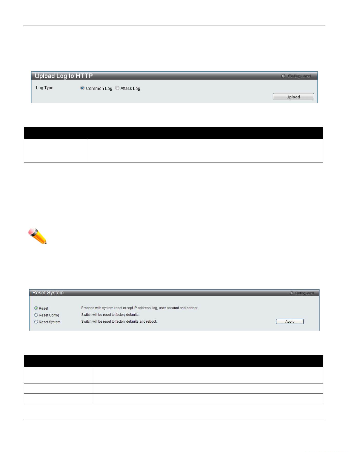
xStack® DGS-3420 Series Layer 2 Managed Stackable Gigabit Switch Web UI Reference Guide
452
Upload Log to HTTP
This window allows the user to upload the log file from the Switch to a computer.
Figure 12-19 Upload Log to HTTP window
The fields that can be configured are described below:
Parameter Description
Log Type Select the type of log to be transferred. Selecting the Common Log option here will upload
the common log entries. Selecting the Attack Log option here will upload the log
concerning attacks.
Click Upload to initiate the upload.
Reset
The Reset function has several options when resetting the Switch. Some of the current configuration parameters can
be retained while resetting all other configuration parameters to their factory defaults.
NOTE: Only the Reset System option will enter the factory default parameters into the Switch's non-
volatile RAM, and then restart the Switch. All other options enter the factory defaults into the
current configuration, but do not save this configuration. Reset System will return the Switch's
configuration to the state it was when it left the factory
Reset gives the option of retaining the Switch's User Accounts and History Log while resetting all other configuration
parameters to their factory defaults. If the Switch is reset using this window, and Save Changes is not executed, the
Switch will return to the last saved configuration when rebooted.
Figure 12-20 Reset System window
The fields that can be configured are described below:
Parameter Description
Reset Selecting this option will factory reset the Switch but not the IP Address, User Accounts
and the Banner.
Reset Config
Selecting this option will factory reset the Switch but not perform a Reboot.
Reset System
Selecting this option will factory reset the Switch and perform a Reboot.
Click the Apply button to initiate the Reset action.
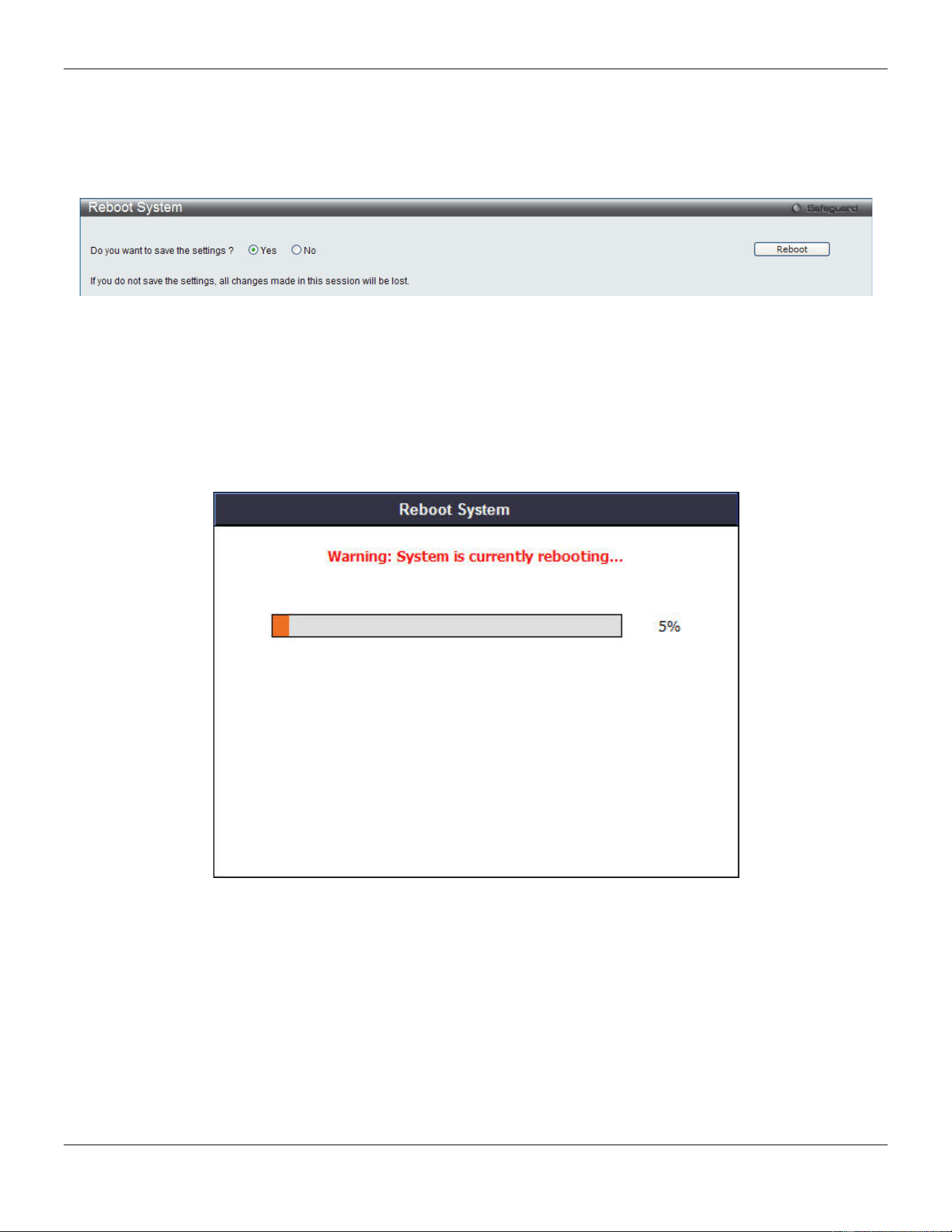
xStack® DGS-3420 Series Layer 2 Managed Stackable Gigabit Switch Web UI Reference Guide
453
Reboot System
The following window is used to restart the Switch.
Figure 12-21 Reboot System Window
Selecting the Yes radio button will instruct the Switch to save the current configuration to non-volatile RAM before
restarting the Switch.
Selecting the No radio button instructs the Switch not to save the current configuration before restarting the Switch. All
of the configuration information entered from the last time Save Changes was executed will be lost.
Click the Reboot button to restart the Switch.
Figure 12-22 System Rebooting window

xStack® DGS-3420 Series Layer 2 Managed Stackable Gigabit Switch Web UI Reference Guide
454
Appendix A - Password Recovery Procedure
This document describes the procedure for resetting passwords on D-Link Switches.
Authenticating any user who tries to access networks is necessary and important. The basic authentication method
used to accept qualified users is through a local login, utilizing a Username and Password. Sometimes, passwords get
forgotten or destroyed, so network administrators need to reset these passwords. This document will explain how the
Password Recovery feature can help network administrators reach this goal.
The following steps explain how to use the Password Recovery feature on D-Link devices to easily recover passwords.
Complete these steps to reset the password:
1. For security reasons, the Password Recovery feature requires the user to physically access the device.
Therefore this feature is only applicable when there is a direct connection to the console port of the device.
It is necessary for the user needs to attach a terminal or PC with terminal emulation to the console port of
the switch.
2. Power on the Switch. After the UART init is loaded to 100%, the Switch will allow 2 seconds for the user to
press the hotkey [^] (Shift + 6) to enter the “Password Recovery Mode.” Once the Switch enters the
“Password Recovery Mode,” all ports on the Switch will be disabled.
Boot Procedure V1.00.003
-------------------------------------------------------------------------------
Power On Self Test ........................................ 100 %
MAC Address : 00-01-02-03-04-00
H/W Version : B1
Please Wait, Loading V1.50.010 Runtime Image .............. 100 %
UART init ................................................. 100 %
Password Recovery Mode
>
1. In the “Password Recovery Mode” only the following commands can be used.
Command Parameters
reset config
{force_agree}
The reset config command resets the whole configuration back to the default values. The
option 'force_agree' means to reset the whole configuration without the user’s agreement.
reboot
{force_agree}
The reboot command exits the Reset Password Recovery Mode and restarts the switch. A
confirmation message will be displayed to allow the user to save the current settings. The
option 'force_agree' means to reset the whole configuration without the user’s agreement.
reset account
The reset account command deletes all the previously created accounts.
reset password
{<username>}
The reset password command resets the password of the specified user. If a username is
not specified, the passwords of all users will be reset.
show account
The show account command displays all previously created accounts.

xStack® DGS-3420 Series Layer 2 Managed Stackable Gigabit Switch Web UI Reference Guide
455
Appendix B - System Log Entries
The following table lists all possible entries and their corresponding meanings that will appear in the System Log of this
Switch.
Category Log Description Severity Note
MAC-based
Access Control
Event description: A host failed to pass the authentication
Log Message: MAC-based Access Control unauthenticated host (MAC:
<macaddr>, Port <[unitID:]portNum>, VID: <vid>)
Parameters description:
macaddr: MAC address
unitID: The unit ID.
portNum: The port number.
vid: VLAN ID on which the host exists
Critical
Event description: The authorized user number on a port has reached the
maximum user limit.
Log Message: Port < [unitID:]portNum> enters MAC-based Access Control
stop learning state.
Parameters description:
unitID: The unit ID.
portNum: The port number.
Warning
Event description: The authorized user number on a port is below the
maximum user limit in a time interval (interval is project dependent).
Log Message: Port <[unitID:]portNum> recovers from MAC-based Access
Control stop learning state.
Parameters description:
unitID: The unit ID.
portNum: The port number.
Warning
Event description: The authorized user number on the whole device has
reached the maximum user limit.
Log Message: MAC-based Access Control enters stop learning state.
Parameters description:
None
Warning
Event description: The authorized user number on the whole device is below
the maximum user limit in a time interval (interval is project dependent).
Log Message: MAC-based Access Control recovers from stop learning state.
Parameters description:
None
Warning
Event description: A host has passed the authentication.
Log Message: MAC-based Access Control host login successful (MAC:
<macaddr>, port: <[unitID]portNum>, VID: <vid>)
Parameters description:
macaddr: The MAC address.
unitID: The unit ID.
portNum: The port number.
Informational

xStack® DGS-3420 Series Layer 2 Managed Stackable Gigabit Switch Web UI Reference Guide
456
vid: The VLAN ID on which the host exists.
Event description: A host has aged out.
Log Message: MAC-based Access Control host aged out (MAC: <macaddr>,
port: <[unitID]portNum>, VID: <vid>)
Parameters description:
macaddr: The MAC address
unitID: The unit ID.
portNum: The port number.
vid: The VLAN ID on which the host exists.
Informational
PTP
Event description: PTP port role changed
Log Message: PTP port <[unitID:]portNum> role changed to <ptp_role>.
Parameters description:
unitID: The unit ID.
portNum: The port number.
ptp_role: The PTP role of the port.
Informational
Event description: PTP clock synchronized
Log Message: The boundary clock synchronized to its master, the offset value
is <+|-><Offset> second(s).
Parameters description:
Offset: The value of the offset between the slave and master.
Informational Only when the
synchronized more than
one second, this log
message will be send.
DHCPv6 Client
Event description: DHCPv6 client interface administrator state changed.
Log Message: DHCPv6 client on interface <ipif-name> changed state to
[enabled | disabled].
Parameters description:
<ipif-name>: Name of the DHCPv6 client interface.
Informational
Event description: DHCPv6 client obtains an ipv6 address from a DHCPv6
server.
Log Message: DHCPv6 client obtains an ipv6 address < ipv6address > on
interface <ipif-name>.
Parameters description:
ipv6address: ipv6 address obtained from a DHCPv6 server.
ipif-name: Name of the DHCPv6 client interface.
Informational
Event description: The ipv6 address obtained from a DHCPv6 server starts
renewing.
Log Message: The IPv6 address < ipv6address > on interface <ipif-name>
starts renewing.
Parameters description:
ipv6address: ipv6 address obtained from a DHCPv6 server.
ipif-name: Name of the DHCPv6 client interface.
Informational
Event description: The ipv6 address obtained from a DHCPv6 server renews
success.
Log Message: The IPv6 address < ipv6address > on interface <ipif-name>
renews success.
Parameters description:
ipv6address: ipv6 address obtained from a DHCPv6 server.
Informational

xStack® DGS-3420 Series Layer 2 Managed Stackable Gigabit Switch Web UI Reference Guide
457
ipif-name: Name of the DHCPv6 client interface.
Event description: The ipv6 address obtained from a DHCPv6 server starts
rebinding
Log Message: The IPv6 address < ipv6address > on interface <ipif-name>
starts rebinding.
Parameters description:
ipv6address: ipv6 address obtained from a DHCPv6 server.
ipif-name: Name of the DHCPv6 client interface.
Informational
Event description: The ipv6 address obtained from a DHCPv6 server rebinds
success
Log Message: The IPv6 address < ipv6address > on interface <ipif-name>
rebinds success.
Parameters description:
ipv6address: ipv6 address obtained from a DHCPv6 server.
ipif-name: Name of the DHCPv6 client interface..
Informational
Event description: The ipv6 address from a DHCPv6 server was deleted.
Log Message: The IPv6 address < ipv6address > on interface <ipif-
name> was
deleted.
Parameters description:
ipv6address: ipv6 address obtained from a DHCPv6 server.
ipif-name: Name of the DHCPv6 client interface.
Informational
DHCPv6 Relay
Event description: DHCPv6 relay on a specify interface’s administrator state
changed
Log Message: DHCPv6 relay on interface <ipif-name> changed state to
[enabled | disabled]
Parameters description:
<ipif-name>: Name of the DHCPv6 relay agent interface.
Informational
DHCPv6 Server
Event description: The address of the DHCPv6 Server pool is used up
Log Message: The address of the DHCPv6 Server pool <pool-name> is used
up.
Parameters description:
<pool-name>: Name of the DHCPv6 Server pool.
Informational
Event description: The number of allocated ipv6 addresses is equal to 4096
Log Message: The number of allocated ipv6 addresses of the DHCPv6 Server
pool is equal to 4096.
Parameters description:
Informational
RCP
Event description: Firmware upgraded successfully.
Log Message: [Unit <unitID>,] Firmware upgraded by <session> successfully.
(Username: <username>, IP: <ipaddr>, MAC: <macaddr>)
Parameters description:
unitID: Represent the id of the device in the stacking system.
session: The user’s session.
username: Represent current login user.
ipaddr: Represent client IP address.
macaddr : Represent client MAC address.
Informational

xStack® DGS-3420 Series Layer 2 Managed Stackable Gigabit Switch Web UI Reference Guide
458
Event description: Firmware upgrade unsuccessfully.
Log Message: [Unit <unitID>,] Firmware upgrade by <session> unsuccessfully.
(Username: <username>, IP: <ipaddr>, MAC: <macaddr>)
Parameters description:
unitID: Represent the id of the device in the stacking system.
session: The user’s session.
username: Represent current login user.
ipaddr: Represent client IP address.
macaddr : Represent client MAC address.
Warning
Event description: Firmware uploaded successfully.
Log Message: Firmware uploaded by <session> successfully. (Username:
<username>, IP: <ipaddr>, MAC: <macaddr>)
Parameters description:
session: The user’s session.
username: Represent current login user.
ipaddr: Represent client IP address.
macaddr : Represent client MAC address.
Informational
Event description: Firmware upload unsuccessfully.
Log Message: Firmware upload by <session> unsuccessfully. (Username:
<username>, IP: <ipaddr>, MAC: <macaddr>)
Parameters description:
session: The user’s session.
username: Represent current login user.
ipaddr: Represent client IP address.
Warning
Event description: Configuration downloaded successfully.
Log Message: Configuration downloaded by <session> successfully.
(Username: <username>, IP: <ipaddr>, MAC: <macaddr>)
Parameters description:
session: The user’s session.
username: Represent current login user.
ipaddr: Represent client IP address.
macaddr : Represent client MAC address.
Informational
Event description: Configuration download unsuccessfully.
Log Message: Configuration download by <session> unsuccessfully.
(Username: <username>, IP: <ipaddr>, MAC: <macaddr>)
Parameters description:
session: The user’s session.
username: Represent current login user.
ipaddr: Represent client IP address.
macaddr : Represent client MAC address.
Warning
Event description: Configuration uploaded successfully.
Log Message: Configuration uploaded by <session> successfully. (Username:
<username>, IP: <ipaddr>, MAC: <macaddr>)
Parameters description:
session: The user’s session.
username: Represent current login user.
Informational

xStack® DGS-3420 Series Layer 2 Managed Stackable Gigabit Switch Web UI Reference Guide
459
ipaddr: Represent client IP address.
macaddr : Represent client MAC address.
Event description: Configuration upload unsuccessfully.
Log Message: Configuration upload by <session> unsuccessfully. (Username:
<username>, IP: <ipaddr>, MAC: <macaddr>)
Parameters description:
session: The user’s session.
username: Represent current login user.
ipaddr: Represent client IP address.
macaddr : Represent client MAC address.
Warning
Event description: Log message uploaded successfully.
Log Message: Log message uploaded by <session> successfully. (Username:
<username>, IP: <ipaddr>, MAC: <macaddr>)
Parameters description:
session: The user’s session.
username: Represent current login user.
ipaddr: Represent client IP address.
macaddr : Represent client MAC address.
Informational
Event description: Log message upload unsuccessfully.
Log Message: Log message upload by <session> unsuccessfully. (Username:
<username>, IP: <ipaddr>, MAC: <macaddr>)
Parameters description:
session: The user’s session.
username: Represent current login user.
ipaddr: Represent client IP address.
macaddr : Represent client MAC address.
Warning
Event description: The downloaded configurations executed successfully.
Log Message: The downloaded configurations executed by <session>
successfully. (Username: <username>, IP: <ipaddr>, MAC: <macaddr>)
Parameters description:
session: The user’s session.
username: Represent current login user.
ipaddr: Represent client IP address.
macaddr : Represent client MAC address.
Informational
Event description: The downloaded configurations execute unsuccessfully.
Log Message: The downloaded configurations executed by <session>
unsuccessfully. (Username: <username>, IP: <ipaddr>, MAC: <macaddr>)
Parameters description:
session: The user’s session.
username: Represent current login user.
ipaddr: Represent client IP address.
macaddr : Represent client MAC address.
Warning
Event description: Attack log message uploaded successfully.
Log Message: Attack log message uploaded by <session> successfully.
(Username: <username>, IP: <ipaddr>, MAC: <macaddr>)
Parameters description:
Informational

xStack® DGS-3420 Series Layer 2 Managed Stackable Gigabit Switch Web UI Reference Guide
460
session: The user’s session.
username: Represent current login user.
ipaddr: Represent client IP address.
macaddr : Represent client MAC address.
Event description: Attack log message upload unsuccessfully.
Log Message: Attack log message upload by <session> unsuccessfully.
(Username: <username>, IP: <ipaddr>, MAC: <macaddr>)
Parameters description:
session: The user’s session.
username: Represent current login user.
ipaddr: Represent client IP address.
macaddr : Represent client MAC address.
Warning
TFTP Client
Event description: Firmware upgraded successfully.
Log Message: [Unit <unitID>,] Firmware upgraded by <session> successfully
(Username: <username>, IP: <ipaddr>, MAC: <macaddr>)
Parameters description:
UnitID: Represent the id of the device in the stacking system.
session: The user’s session.
Username: Represent current login user.
Ipaddr: Represent client IP address.
macaddr : Represent client MAC address.
Informational
Event description: Firmware upgrade was unsuccessful.
Log Message: [Unit <unitID>,] Firmware upgrade by <session> was
unsuccessful! (Username: <username>, IP: <ipaddr>, MAC: <macaddr>)
Parameters description:
UnitID: Represent the id of the device in the stacking system.
session: The user’s session.
Username: Represent current login user.
Ipaddr: Represent client IP address.
macaddr : Represent client MAC address.
Warning
Event description: Firmware successfully uploaded.
Log Message: Firmware successfully uploaded by <session> (Username:
<username>, IP: <ipaddr>, MAC: <macaddr>)
Parameters description:
session: The user’s session.
Username: Represent current login user.
Ipaddr: Represent client IP address.
macaddr : Represent client MAC address.
Informational
Event description: Firmware upload was unsuccessful.
Log Message: Firmware upload by <session> was unsuccessful! (Username:
<username>, IP: <ipaddr>, MAC: <macaddr>)
Parameters description:
session: The user’s session.
Username: Represent current login user.
Ipaddr: Represent client IP address.
Warning
Event description: Configuration successfully downloaded.
Log Message: Configuration successfully downloaded by <session>
Informational

xStack® DGS-3420 Series Layer 2 Managed Stackable Gigabit Switch Web UI Reference Guide
461
(Username: <username>, IP: <ipaddr>, MAC: <macaddr>)
Parameters description:
session: The user’s session.
Username: Represent current login user.
Ipaddr: Represent client IP address.
macaddr : Represent client MAC address.
Event description: Configuration download was unsuccessful.
Log Message: Configuration download by <session> was unsuccessful!
(Username: <username>, IP: <ipaddr>, MAC: <macaddr>)
Parameters description:
session: The user’s session.
Username: Represent current login user.
Ipaddr: Represent client IP address.
macaddr : Represent client MAC address.
Warning
Event description: Configuration successfully uploaded.
Log Message: Configuration successfully uploaded by <session> (Username:
<username>, IP: <ipaddr>, MAC: <macaddr>)
Parameters description:
session: The user’s session.
Username: Represent current login user.
Ipaddr: Represent client IP address.
macaddr : Represent client MAC address.
Informational
Event description: Configuration upload was unsuccessful.
Log Message: Configuration upload by <session> was unsuccessful!
(Username: <username>, IP: <ipaddr>, MAC: <macaddr>)
Parameters description:
session: The user’s session.
Username: Represent current login user.
Ipaddr: Represent client IP address.
macaddr : Represent client MAC address.
Warning
Event description: Log message successfully uploaded.
Log Message: Log message successfully uploaded by <session> (Username:
<username>, IP: <ipaddr>, MAC: <macaddr>)
Parameters description:
session: The user’s session.
Username: Represent current login user.
Ipaddr: Represent client IP address.
macaddr : Represent client MAC address.
Informational
Event description: Log message upload was unsuccessful.
Log Message: Log message upload by <session> was unsuccessful!
(Username: <username>, IP: <ipaddr>, MAC: <macaddr>)
Parameters description:
session: The user’s session.
Username: Represent current login user.
Ipaddr: Represent client IP address.
macaddr : Represent client MAC address.
Warning

xStack® DGS-3420 Series Layer 2 Managed Stackable Gigabit Switch Web UI Reference Guide
462
Event description: Attack log message successfully uploaded.
Log Message: Attack log message successfully uploaded by <session>
(Username: <username>, IP: <ipaddr>, MAC: <macaddr>)
Parameters description:
session: The user’s session.
Username: Represent current login user.
Ipaddr: Represent client IP address.
macaddr : Represent client MAC address.
Informational
Event description: Attack log message upload was unsuccessful.
Log Message: Attack log message upload by <session> was unsuccessful!
(Username: <username>, IP: <ipaddr>, MAC: <macaddr>)
Parameters description:
session: The user’s session.
Username: Represent current login user.
Ipaddr: Represent client IP address.
macaddr : Represent client MAC address.
Warning
DNS Resolver
Event description: Duplicate Domain name cache added, leads a dynamic
domain name cache be deleted
Log Message: Duplicate Domain name case name: <domainname>, static IP:
<ipaddr>, dynamic IP:<ipaddr>
Parameters description:
domainame: the domain name string.
ipaddr: IP address.
Informational
ARP
Event description: Gratuitous ARP detected duplicate IP.
Log Message: Conflict IP was detected with this device (IP: <ipaddr>, MAC:
<macaddr>, Port <[unitID:]portNum>, Interface: <ipif_name>).
Parameters description:
ipaddr: The IP address which is duplicated with our device.
macaddr: The MAC address of the device that has duplicated IP address as
our device.
unitID: 1.Interger value;2.Represent the id of the device in the stacking system.
portNum: 1.Interger value;2.Represent the logic port number of the device.
ipif_name: The name of the interface of the switch which has the conflic IP
address.
Warning
Telnet
Event description: Successful login through Telnet.
Log Message: Successful login through Telnet (Username: <username>, IP:
<ipaddr>)
Parameters description:
ipaddr: The IP address of telnet client.
username: the user name that used to login telnet server.
Informational
Event description: Login failed through Telnet.
Log Message: Login failed through Telnet (Username: <username>, IP:
<ipaddr>)
Parameters description:
ipaddr: The IP address of telnet client.
username: the user name that used to login telnet server.
Warning

xStack® DGS-3420 Series Layer 2 Managed Stackable Gigabit Switch Web UI Reference Guide
463
Event description: Logout through Telnet.
Log Message: Logout through Telnet (Username: <username>, IP: <ipaddr>)
Parameters description:
ipaddr: The IP address of telnet client.
username: the user name that used to login telnet server.
Informational
Event description: Telnet session timed out.
Log Message: Telnet session timed out (Username: <username>, IP:
<ipaddr>).
Parameters description:
ipaddr: The IP address of telnet client.
username: the user name that used to login telnet server.
Informational
Port
Event description: Port link up.
Log Message: Port <[unitID:]portNum> link up, <link state>
Parameters description:
unitID: 1.Interger value;2.Represent the id of the device in the stacking system.
portNum: 1.Interger value;2.Represent the logic port number of the device.
link state: for ex: , 100Mbps FULL duplex
Informational
Event description: Port link down.
Log Message: Port <[unitID:]portNum> link down
Parameters description:
unitID: 1.Interger value;2.Represent the id of the device in the stacking system.
portNum: 1.Interger value;2.Represent the logic port number of the device.
Informational
802.1X
Event description: 802.1X Authentication failure.
Log Message: 802.1X Authentication failure [for <reason> ] from (Username:
<username>, Port: <[unitID:]portNum>, MAC: <macaddr> )
Parameters description:
reason: The reason for the failed authentication.
username: The user that is being authenticated.
unitID: The unit ID.
portNum: The switch port number.
macaddr: The MAC address of thr authenticated device.
Warning
Event description: 802.1X Authentication successful.
Log Message: 802.1X Authentication successful from (Username:
<username>, Port: <[unitID:]portNum>, MAC: <macaddr>)
Parameters description:
username: The user that is being authenticated.
unitID: The unit ID.
portNum: The switch port number.
macaddr: The MAC address of the authenticated device.
Informational
RADIUS
Event description: VID assigned from RADIUS server after RADIUS client is
authenticated by RADIUS server successfully .This VID will be assigned to the
port and this port will be the VLAN untagged port member.
Log Message: RADIUS server <ipaddr> assigned VID :<vlanID> to port
<[unitID:]portNum> (account :<username> )
Parameters description:
Informational

xStack® DGS-3420 Series Layer 2 Managed Stackable Gigabit Switch Web UI Reference Guide
464
ipaddr: The IP address of the RADIUS server.
vlanID: The VID of RADIUS assigned VLAN.
unitID: The unit ID.
portNum: The port number.
Username: The user that is being authenticated.
Event description: Ingress bandwidth assigned from RADIUS server after
RADIUS client is authenticated by RADIUS server successfully .This Ingress
bandwidth will be assigned to the port.
Log Message: RADIUS server <ipaddr> assigned ingress
bandwidth :<ingressBandwidth> to port <[unitID:]portNum> (account :
<username>)
Parameters description:
ipaddr: The IP address of the RADIUS server.
ingressBandwidth: The ingress bandwidth of RADIUS assign.
unitID: The unit ID.
portNum: The port number.
Username: The user that is being authenticated.
Informational
Event description: Egress bandwidth assigned from RADIUS server after
RADIUS client is authenticated by RADIUS server successfully .This egress
bandwidth will be assigned to the port.
Log Message: RADIUS server <ipaddr> assigned egress
bandwidth :<egressBandwidth> to port <[unitID:]portNum> (account:
<username>)
Parameters description:
ipaddr: The IP address of the RADIUS server.
egressBandwidth: The egress bandwidth of RADIUS assign.
unitID: The unit ID.
portNum: The port number.
Username: The user that is being authenticated.
Informational
Event description: 802.1p default priority assigned from RADIUS server after
RADIUS client is authenticated by RADIUS server successfully. This 802.1p
default priority will be assigned to the port.
Log Message: RADIUS server <ipaddr> assigned 802.1p default
priority:<priority> to port <[unitID:]portNum> (account : <username>)
Parameters description:
ipaddr: The IP address of the RADIUS server.
priority: Priority of RADIUS assign.
unitID: The unit ID.
portNum: The port number.
Username: The user that is being authenticated.
Informational
Event description: Failed to assign ACL profiles/rules from RADIUS server.
Log Message: RADIUS server <ipaddr> assigns <username> ACL failure at
port <[unitID]portNum> (<string>)
Parameters description:
ipaddr: The IP address of the RADIUS server.
unitID: The unit ID.
portNum: The port number.
Username: The user that is being authenticated.
string: The failed RADIUS ACL command string.
Warning

xStack® DGS-3420 Series Layer 2 Managed Stackable Gigabit Switch Web UI Reference Guide
465
LLDP-MED
Event description: LLDP-MED topology change detected
Log Message: LLDP-MED topology change detected (on port <portNum>.
chassis id: <chassisType>, <chassisID>, port id: <portType>, <portID>, device
class: <deviceClass>)
Parameters description:
portNum: The port number.
chassisType: chassis ID subtype.
Value list:
1. chassisComponent(1)
2. interfaceAlias(2)
3. portComponent(3)
4. macAddress(4)
5. networkAddress(5)
6. interfaceName(6)
7. local(7)
chassisID: chassis ID.
portType: port ID subtype.
Value list:
1. interfaceAlias(1)
2. portComponent(2)
3. macAddress(3)
4. networkAddress(4)
5. interfaceName(5)
6. agentCircuitId(6)
7. local(7)
portID: port ID.
deviceClass: LLDP-MED device type.
Notice
Event description: Conflict LLDP-MED device type detected
Log Message: Conflict LLDP-MED device type dete
cted ( on port < portNum >,
chassis id: < chassisType>, <chassisID>, port id: < portType>, <portID>,
device class: <deviceClass>)
Parameters description:
portNum: The port number.
chassisType: chassis ID subtype.
Value list:
1. chassisComponent(1)
2. interfaceAlias(2)
3. portComponent(3)
4. macAddress(4)
5. networkAddress(5)
6. interfaceName(6)
7. local(7)
chassisID: chassis ID.
portType: port ID subtype.
Value list:
1. interfaceAlias(1)
2. portComponent(2)
3. macAddress(3)
4. networkAddress(4)
5. interfaceName(5)
Notice

xStack® DGS-3420 Series Layer 2 Managed Stackable Gigabit Switch Web UI Reference Guide
466
6. agentCircuitId(6)
7. local(7)
portID: port ID.
deviceClass: LLDP-MED device type.
Event description: Incompatible LLDP-MED TLV set detected
Log Message: Incompatible LLDP-MED TLV set detected ( on port < portNum
>, chassis id: < chassisType>, <chassisID>, port id: < portType>, <portID>,
device class: <deviceClass>)
Parameters description:
portNum: The port number.
chassisType: chassis ID subtype.
Value list:
1. chassisComponent(1)
2. interfaceAlias(2)
3. portComponent(3)
4. macAddress(4)
5. networkAddress(5)
6. interfaceName(6)
7. local(7)
chassisID: chassis ID.
portType: port ID subtype.
Value list:
1. interfaceAlias(1)
2. portComponent(2)
3. macAddress(3)
4. networkAddress(4)
5. interfaceName(5)
6. agentCircuitId(6)
7. local(7)
portID: port ID.
deviceClass: LLDP-MED device type.
Notice
Voice VLAN
Event description: When a new voice device is detected in the port.
Log Message: New voice device detected (Port <portNum>, MAC <macaddr>)
Parameters description:
portNum : The port number.
macaddr: Voice device MAC address
Informational
Event description: When a port which is in auto Voice VLAN mode joins the
Voice VLAN
Log Message: Port < portNum > add into Voice VLAN <vid >
Parameters description:
portNum : The port number.
vid:VLAN ID
Informational
Event description: When a port leaves the Voice VLAN and at the same time,
no voice device is detected in the aging interval for that port, the log message
will be sent.
Log Message: Port < portNum > remove from Voice VLAN <vid >
Parameters description:
portNum : The port number.
Informational

xStack® DGS-3420 Series Layer 2 Managed Stackable Gigabit Switch Web UI Reference Guide
467
vid:VLAN ID
DULD
Event description: A unidirectional link has been detected on this port
Log Message: [DULD(1):] port:<[unitID:]
portNum> is unidirectional.
Parameters description:
unitID: the unit ID
portNum: port number
Informational
Stacking
Event description: Hot insertion.
Log Message: Unit: <unitID>, MAC: <macaddr> Hot insertion.
Parameters description:
unitID: Box ID.
Macaddr: MAC address.
Informational
Event description: Hot removal.
Log Message: Unit: <unitID>, MAC: <macaddr> Hot removal.
Parameters description:
unitID: Box ID.
Macaddr: MAC address.
Informational
Event description: Stacking topology change.
Log Message: Stacking topology is <Stack_TP_TYPE>. Master(Unit <unitID>,
MAC:<macaddr>).
Parameters description:
Stack_TP_TYPE: The stacking topology type is one of the following:
1. Ring,
2. Chain.
unitID: Box ID.
Macaddr: MAC address.
Informational
Event description: Backup master changed to master.
Log Message: Backup master changed to master. Master (Unit: <unitID>).
Parameters description:
unitID: Box ID.
Informational
Event description: Slave changed to master
Log Message: Slave changed to master. Master (Unit: <unitID>).
Parameters description:
unitID: Box ID.
Informational
Event description: Box ID conflict.
Log Message: Hot insert failed, box ID conflict: Unit <unitID> conflict (MAC:
<macaddr> and MAC: <macaddr>).
Parameters description:
unitID: Box ID.
macaddr: The MAC addresses of the conflicting boxes.
Critical
SNMP
Event Description: SNMP request received with invalid community string
Log Message: SNMP request received from <ipaddr> with invalid community
string.
Informational

xStack® DGS-3420 Series Layer 2 Managed Stackable Gigabit Switch Web UI Reference Guide
468
Parameters Description:
ipaddr: The IP address.
Web (SSL)
Event description: Successful login through Web.
Log Message: Successful login through Web (Username: <username>, IP:
<ipaddr>).
Parameters description:
username: The use name that used to login HTTP server.
ipaddr: The IP address of HTTP client.
Informational
Event description: Login failed through Web.
Log Message: Login failed through Web (Username: <username>, IP:
<ipaddr>).
Parameters description:
username: The use name that used to login HTTP server.
ipaddr: The IP address of HTTP client.
Warning
Event description: Web session timed out.
Log Message: Web session timed out (Username: <usrname>, IP: <ipaddr>).
Parameters description:
username: The use name that used to login HTTP server.
ipaddr: The IP address of HTTP client.
Informational
Event description: Logout through Web.
Log Message: Logout through Web (Username: %S, IP: %S).
Parameters description:
username: The use name that used to login HTTP server.
ipaddr: The IP address of HTTP client.
Informational
Event description: Successful login through Web (SSL).
Log Message: Successful login through Web (SSL) (Username: <username>,
IP: <ipaddr>).
Parameters description:
username: The use name that used to login SSL server.
ipaddr: The IP address of SSL client.
Informational
Event description: Login failed through Web (SSL).
Log Message: Login failed through Web (SSL) (Username: <username>, IP:
<ipaddr>).
Parameters description:
username: The use name that used to login SSL server.
ipaddr: The IP address of SSL client.
Warning
Event description: Web (SSL) session timed out.
Log Message: Web (SSL) session timed out (Username: <username>, IP:
<ipaddr>).
Parameters description:
username: The use name that used to login SSL server.
ipaddr: The IP address of SSL client.
Information
Event description: Logout through Web (SSL).
Log Message: Logout through Web (SSL) (Username: <username>, IP:
Information

xStack® DGS-3420 Series Layer 2 Managed Stackable Gigabit Switch Web UI Reference Guide
469
<ipaddr>).
Parameters description:
username: The use name that used to login SSL server.
ipaddr: The IP address of SSL client.
Port Security
Event description: Address full on a port
Log Message: Port security violation
(MAC: < macaddr > on port:: < unitID: portNum >)
Parameters description:
macaddr: The violation MAC address.
unitID: The unit ID.
portNum: The port number.
Warning
Safe Guard
Event description: The host enters the mode of normal.
Log Message: Unit< unitID >, Safeguard Engine enters NORMAL mode
Parameters description:
unitID: The unit ID.
Informational
Event description: The host enters the mode of exhausted.
Log Message: Unit< unitID >, Safeguard Engine enters EXHAUSTED mode
Parameters description:
unitID: The unit ID.
Warning
DoS
Event description: The DOS is possibly snoofed.
Log Message: Possible spoofing attack from IP: <ipaddr>, MAC: <macaddr>,
port: <unitID: portNum>
Parameters description:
Ipaddr: The ip address
macaddr: The violation MAC address.
unitID: The unit ID.
portNum: The port number.
Critical
Event Description: The DoS attack is blocked
Log Message: <dos_name> is blocked from (IP: <ipaddr> Port: <[unit
ID:]portNum>)
Parameters Description:
dos_name: The type of DoS attack will be one of the followings
ipaddr: IP address of attacker
portNum: the attacked port.
Informational
AAA
Event description: Successful login.
Log Message: Successful login through <Console | Telnet | Web (SSL) |
SSH>(Username: <username>, IP: <ipaddr | ipv6address>).
Parameters description:
ipaddr: IP address.
username: user name.
ipv6address: IPv6 address.
Informational
Event description: Login failed.
Log Message: Login failed through <Console | Telnet | Web (SSL)| SSH>
(Username: <username>, IP: <ipaddr | ipv6address>).
Parameters description:
ipaddr: IP address.
username: user name.
Warning

xStack® DGS-3420 Series Layer 2 Managed Stackable Gigabit Switch Web UI Reference Guide
470
ipv6address: IPv6 address.
Event description: Logout.
Log Message: Logout through <Console | Telnet | Web (SSL)| SSH>
(Username: <username>, IP: <ipaddr | ipv6address>).
Parameters description:
ipaddr: IP address.
username: user name.
ipv6address: IPv6 address.
Informational
Event description: session timed out.
Log Message: <Console | Telnet | Web (SSL)| SSH> session timed out
(Username: <username>, IP: <ipaddr | ipv6address>).
Parameters description:
ipaddr: IP address.
username: user name.
ipv6address: IPv6 address.
Informational
Event description: SSH server is enabled.
Log Message: SSH server is enabled
Informational
Event description: SSH server is disabled.
Log Message: SSH server is disabled
Informational
Event description: Authentication Policy is enabled.
Log Message: Authentication Policy is enabled (Module: AAA).
Informational
Event description: Authentication Policy is disabled.
Log Message: Authentication Policy is disabled (Module: AAA).
Informational
Event description: Login failed due to AAA server timeout or improper
configuration.
Log Message: Login failed through <Console | Telnet | Web (SSL)| SSH> from
<ipaddr | ipv6address> due to AAA server <ipaddr | ipv6address> timeout or
improper configuration (Username: <username>).
Parameters description:
ipaddr: IP address.
ipv6address: IPv6 address.
username: user name.
Warning
Event description: Successful Enable Admin authenticated by AAA local or
none or server.
Log Message: Successful Enable Admin through <Console | Telnet | Web
(SSL)| SSH> from <ipaddr | ipv6address> authenticated by AAA <local | none |
server <ipaddr | ipv6address>> (Username: <username>).
Parameters description:
local: enable admin by AAA local method.
none: enable admin by AAA none method.
server: enable admin by AAA server method.
ipaddr: IP address.
ipv6address: IPv6 address.
username: user name.
Informational
Event description: Enable Admin failed due to AAA server timeout or improper
configuration.
Log Message: Enable Admin failed through <Console | Telnet | Web(SSL)|
SSH> from <ipaddr | ipv6address> due to AAA server <ipaddr | ipv6address>
Warning

xStack® DGS-3420 Series Layer 2 Managed Stackable Gigabit Switch Web UI Reference Guide
471
timeout or improper configuration (Username: <username>)
Parameters description:
ipaddr: IP address.
ipv6address: IPv6 address.
username: user name.
Event description: Enable Admin failed authenticated by AAA local or server.
Log Message: Enable Admin failed through <Console | Telnet | Web (SSL)|
SSH> from <ipaddr | ipv6address> authenticated by AAA < local | server
<ipaddr | ipv6address>> (Username: <username>).
Parameters description:
local: enable admin by AAA local method.
server: enable admin by AAA server method.
ipaddr: IP address.
ipv6address: IPv6 address.
username: user name.
Warning
Event description: Successful login authenticated by AAA local or none or
server.
Log Message: Successful login through <Console | Telnet | Web (SSL) |
SSH>
from < ipaddr | ipv6address > authenticated by AAA <local | none | server
<ipaddr | ipv6address>> (Username: <username>).
Parameters description:
local: specify AAA local method.
none: specify none method.
server: specify AAA server method.
ipaddr: IP address.
ipv6address: IPv6 address.
username: user name.
Informational
Event description: Login failed authenticated by AAA local or server.
Log Message: Login failed through <Console | Telnet | Web (SSL)| SSH> from
<ipaddr | ipv6address> authenticated by AAA <local | server <ipaddr |
ipv6address>> (Username: <username>).
Parameters description:
local: specify AAA local method.
server: specify AAA server method.
ipaddr: IP address.
ipv6address: IPv6 address.
username: user name.
Warning
WAC
Event description: When a client host fails to authenticate.
Log Message: WAC unauthenticated user (User Name: <string>, IP: <ipaddr |
ipv6address>, MAC: <macaddr>, Port: <[unitID:]portNum>)
Parameters description:
string: User name
ipaddr: IP address
ipv6address: IPv6 address
macaddr: MAC address
unitID: The unit ID
portNum : The port number
Warning

xStack® DGS-3420 Series Layer 2 Managed Stackable Gigabit Switch Web UI Reference Guide
472
Event description: This log will be triggered when the number of authorized
users reaches the maximum user limit on the whole device.
Log Message: WAC enters stop learning state.
Warning
Event description: This log will be triggered when the number of authorized
users is below the maximum user limit on whole device in a time interval (5
min).
Log Message: WAC recovered from stop learning state.
Warning
Event description: When a client host authenticated successful.
Log Message: WAC authenticated user (Username: <string>, IP: <ipaddr |
ipv6address>, MAC: <macaddr>, Port: <[unitID:] portNum>)
Parameters description:
string: User name
ipaddr: IP address
ipv6address: IPv6 address
macaddr: MAC address
unitID: The unit ID
portNum : The port number
Informational
JWAC
Event description: When a client host authenticated successful.
Log Message: JWAC authenticated user (Username: <string>, IP: <ipaddr>,
MAC: <macaddr>, Port: <[unitID:]portNum>)
Parameters description:
string: Username
ipaddr: IP address
macaddr: MAC address
unitID: The unit ID
portNum : The port number
Informational
Event description: When a client host fails to authenticate.
Log Message: JWAC unauthenticated user (User N
ame: <string>, IP: <ipaddr>,
MAC: <macaddr>, Port: <[unitID:]portNum>)
Parameters description:
string: User name
ipaddr: IP address
macaddr: MAC address
unitID: The unit ID
portNum : The port number
Warning
Event description: This log will be triggered when the number of authorized
users reaches the maximum user limit on the whole device.
Log Message: JWAC enters stop learning state.
Warning
Event description: This log will be triggered when the number of authorized
users is below the maximum user limit on the whole device in a time interval (5
min).
Log Message: JWAC recovered from stop learning state.
Warning
LBD
Event Description: Loop back is detected under port-based mode.
Log Message:
Port < [unitID:] portNum> LBD loop occurred. Port blocked.
Parameters Description:
portNum: The port number.
Critical
Event Description: Port recovered from LBD blocked state under port-based Informational

xStack® DGS-3420 Series Layer 2 Managed Stackable Gigabit Switch Web UI Reference Guide
473
mode.
Log Message:
Port < [unitID:] portNum>LBD port recovered. Loop detection restarted
Parameters Description:
portNum: The port number.
Event Description: Loop back is detected under VLAN-based mode.
Log Message:
Port < [unitID:] portNum> VID <vlanID> LBD loop occurred. Packet discard
begun
Parameters Description:
portNum: The port number.
vlanID: the VLAN ID number.
Critical
Event Description: Port recovered from LBD blocked state under VLAN-based
mode.
Log Message:
Port < [unitID:] portNum> VID <vlanID> LBD recovered. Loop detection
restarted
Parameters Description:
portNum: The port number.
vlanID: the VLAN ID number.
Informational
Event Description: The number of VLAN in which loop back occurs hit the
specified number.
Log Message:
Loop VLAN number overflow.
Parameters Description:
None
Informational
IMPB
Event description: Dynamic IMPB entry conflicts with static ARP.
Log Message: Dynamic IMPB entry conflicts with static ARP(IP: <ipaddr>,
MAC: <macaddr>, Port <[unitID:]portNum>)
Parameters description:
ipaddr: IP address
macaddr: MAC address
unitID: The unit ID
portNum : The port number
Warning
Event description: Dynamic IMPB entry conflicts with static FDB.
Log Message: Dynamic IMPB entry conflicts with static FDB(IP: [<ipaddr> |
<ipv6addr>], MAC: <macaddr>, Port <[unitID:]portNum>)
Parameters description:
ipaddr: IP address
ipv6addr: IPv6 address
macaddr: MAC address
unitID: The unit ID
portNum : The port number
Warning
Event description: Dynamic IMPB entry conflicts with static IMPB.
Log Message: Dynamic IMPB entry conflicts with static IMPB(IP: [<ipaddr> |
<ipv6addr>], MAC: <macaddr>, Port <[unitID:]portNum>).
Parameters description:
ipaddr: IP address
ipv6addr: IPv6 address
Warning

xStack® DGS-3420 Series Layer 2 Managed Stackable Gigabit Switch Web UI Reference Guide
474
macaddr: MAC address
unitID: The unit ID
portNum : The port number
Event description: Creating IMPB entry failed due to no ACL rule being
available.
Log Message: Creating IMPB entry failed due to no ACL rule being
available(IP:[<ipaddr> | <ipv6addr>], MAC: <macaddr>, Port
<[unitID:]portNum>)
Parameters description:
ipaddr: IP address
ipv6addr: IPv6 address
macaddr: MAC address
unitID: The unit ID
portNum : The port number
Warning
Event description: IMPB checks a host illegal.
Log Message: Unauthenticated IP-
MAC address and discarded by IMPB (IP: [<
ipaddr > | < ipv6addr >], MAC :< macaddr >, Port <[unitID:]portNum >).
Parameters description:
ipaddr: IP address
ipv6addr: IPv6 address
macaddr: MAC address
unitID: The unit ID
portNum : The port number
Warning
Event description: Dynamic IMPB entry conflicts with static ND
Log Message: Dynamic IMPB entry conflicts with static ND (IP: [< ipaddr > | <
ipv6addr >], MAC: <macaddr>, Port <[unitID:]portNum>)
Parameters description:
ipaddr: IP address
ipv6addr: IPv6 address
macaddr: MAC address
unitID: The unit ID
portNum : The port number
Warning
Traffic Control
Event description: Broadcast storm occurrence.
Log Message: Port <unitID: portNum> Broadcast storm is occurring.
Parameters description:
unitID: The unit ID.
portNum: The port number.
Warning
Event description: Broadcast storm cleared.
Log Message: Port <unitID: portNum> broadcast storm has cleared.
Parameters description:
unitID: The unit ID.
portNum: The port number.
Informational
Event description: Multicast storm occurrence.
Log Message: Port <unitID: portNum> Multicast storm is occurring.
Parameters description:
unitID: The unit ID.
Warning

xStack® DGS-3420 Series Layer 2 Managed Stackable Gigabit Switch Web UI Reference Guide
475
portNum: The port number.
Event description: Multicast Storm cleared.
Log Message: Port <unitID: portNum>multicast storm has cleared.
Parameters description:
unitID: The unit ID.
portNum: The port number.
Informational
Event description: Port shut down due to a packet storm
Log Message: Port <[unitID:]portNum> is currently shut down due to the
<packet-type> storm
Parameters description:
unitID: The unit ID.
portNum: The port number.
packet-type: The storm packet type, include multicast
and broadcast.
Warning
DHCP Server
Screening
Event description: Detected untrusted DHCP server IP address.
Log Message: Detected untrusted DHCP server(IP: <ipaddr>,
Port <portNum> )
Parameters description:
ipaddr: The untrusted IP address which has been is detected
with our device.
portNum : Represent the logic port number of the device.
Informational
Event Description: Detected untrusted DHCPv6 server IP address
Log Message: Detected untrusted DHCPv6 server (IP: <ipv6addr>,
Port:<[unitID:]portNum> )
Parameters Description:
ipv6addr: The untrusted source IP of DHCPv6 server which has been detected
with our device.
unitID: The unit ID.
portNum: The port number.
Informational
Event Description: Detected untrusted source IP in ICMPv6 Router
Advertisement Message.
Log Message: Detected untrusted source IP of ICMPv6 Router Advertisement
message (IP: <ipv6addr>, Port:<[unitID:]portNum> )
Parameters Description:
Ipv6addr: The untrusted ICMPv6 Router Advertisement address which has
been detected with our device
unitID: The unit ID.
portNum: The port number.
Informational
ERPS
Event description: Signal failure detected
Log Message: Signal failure detected on node (MAC: <macaddr>)
Parameters description:
macaddr: The system MAC address of the node
Notice
Event description: Signal failure cleared
Log Message: Signal failure cleared on node (MAC: <macaddr>)
Parameters description:
macaddr: The system MAC address of the node
Notice
Event description: RPL owner conflict
Log Message: RPL owner conflicted on the ring (MAC: <macaddr>)
Warning

xStack® DGS-3420 Series Layer 2 Managed Stackable Gigabit Switch Web UI Reference Guide
476
Parameters description:
macaddr: The system MAC address of the node
MSTP Debug
Enhancement
Event description: Topology changed.
Log Message: Topology changed [( [Instance:<InstanceID> ] ,port:<[unitID:]
portNum> ,MAC: <macaddr>)]
Parameters description:
InstanceID: Instance ID.
portNum:Port ID
macaddr: MAC address
Notice
Event description: Spanning Tree new Root Bridge
Log Message: [CIST | CIST Regional | MSTI Regional] New Root bridge
selected( [Instance: <InstanceID> ]MAC: <macaddr> Priority :<value>)
Parameters description:
InstanceID: Instance ID.
macaddr: Mac address
value: priority value
Informational
Event description: Spanning Tree Protocol is enabled
Log Message: Spanning Tree Protocol is enabled
Informational
Event description: Spanning Tree Protocol is disabled
Log Message: Spanning Tree Protocol is disabled
Informational
Event description: New root port
Log Message: New root port selected [( [Instance:<InstanceID> ],
port:<[unitID:] portNum>)]
Parameters description:
InstanceID: Instance ID.
portNum:Port ID
Notice
Event description: Spanning Tree port status changed
Log Message: Spanning Tree port status changed [( [Instance:<InstanceID> ],
port:<[unitID:] portNum>)] <old_status> -> <new_status>
Parameters description:
InstanceID: Instance ID.
portNum: Port ID
old_status: Old status
new_status: New status
Notice
Event description: Spanning Tree port role changed.
Log Message: Spanning Tree port status changed. [( [Instance:<InstanceID> ],
port:<[unitID:] portNum>)] <old_role> -> <new_role>
Parameters description:
InstanceID: Instance ID.
portNum:Port ID/
old_role: Old role
new_status:New role
Informational
Event description: Spanning Tree instance created.
Log Message: Spanning Tree instance created. Instance:<InstanceID>
Parameters description:
Informational

xStack® DGS-3420 Series Layer 2 Managed Stackable Gigabit Switch Web UI Reference Guide
477
InstanceID: Instance ID.
Event description: Spanning Tree instance deleted.
Log Message: Spanning Tree instance deleted. Instance:<InstanceID>
Parameters description:
InstanceID: Instance ID.
Informational
Event description: Spanning Tree Version changed.
Log Message: Spanning Tree version changed. New version:<new_version>
Parameters description:
new_version: New STP version.
Informational
Event description: Spanning Tree MST configuration ID name and revision
level changed.
Log Message: Spanning Tree MST configuration ID name and revision level
changed (name:<name> ,revision level <revision_level>).
Parameters description:
name : New name.
revision_level:New revision level.
Informational
Event description: Spanning Tree MST configuration ID VLAN mapping table
deleted.
Log Message: Spanning Tree MST configuration ID VLAN mapping table
changed (instance: <InstanceID> delete vlan <startvlanid> [- <endvlanid>]).
Parameters description:
InstanceID: Instance ID.
startvlanid- endvlanid:VLANlist
Informational
Event description: Spanning Tree MST configuration ID VLAN mapping table
added.
Log Message: Spanning Tree MST configuration ID VLAN mapping table
changed (instance: <InstanceID> add vlan <startvlanid> [- <endvlanid>]).
Parameters description:
InstanceID: Instance ID.
startvlanid- endvlanid:VLANlist
Informational
CFM
Event description: Cross-connect is detected
Log Message: CFM cross-
connect. VLAN:<vlanid>, Local(MD Level:<mdlevel>,
Port <[unitID:]portNum>, Direction:<mepdirection>) Remote(MEPID:<mepid>,
MAC:<macaddr>)
Parameters description:
vlanid: Represents the VLAN identifier of the MEP.
mdlevel: Represents the MD level of the MEP.
unitID: Represents the ID of the device in the stacking system.
portNum: Represents the logical port number of the MEP.
mepdirection: Can be "inward" or "outward".
mepid: Represents the MEPID of the MEP.
macaddr: Represents the MAC address of the MEP.
Critical
Event description: Error CFM CCM packet is detected
Log Message: MD Level:<mdlevel>, VLAN:<vlanid>, Local(Port
<[unitID:]portNum>, Direction:<mepdirection>) Remote(MEPID:<mepid>,
MAC:<macaddr>)
Warning

xStack® DGS-3420 Series Layer 2 Managed Stackable Gigabit Switch Web UI Reference Guide
478
Parameters description:
vlanid: Represents the VLAN identifier of the MEP.
mdlevel: Represents MD level of the MEP.
unitID: Represents the ID of the device in the stacking system.
portNum: Represents the logical port number of the MEP.
mepdirection: Can be "inward" or "outward".
mepid: Represents the MEPID of the MEP.
macaddr: Represents the MAC address of the MEP.
Event description: Cannot receive the remote MEP's CCM packet
Log Message: CFM remote down. MD Level:<mdlevel>, VLAN:<vlanid>,
Local(Port <[unitID:]portNum>, Direction:<mepdirection>)
Parameters description:
vlanid: Represents the VLAN identifier of the MEP.
mdlevel: Represents the MD level of the MEP.
unitID: Represents the ID of the device in the stacking system.
portNum: Represents the logical port number of the MEP.
mepdirection: Represents the MEP direction, which can be "inward" or
"outward"..
Warning
Event description: Remote MEP's MAC reports an error status
Log Message: CFM remote MAC error. MD Level:<mdlevel>, VLAN:<vlanid>,
Local(Port <[unitID:]portNum>, Direction:<mepdirection>)
Parameters description:
vlanid: Represents the VLAN identifier of the MEP.
mdlevel: Represents the MD level of the MEP.
unitID: Represents the ID of the device in the stacking system.
portNum: Represents the logical port number of the MEP.
mepdirection: Represents the MEP direction, which can be "inward" or
"outward".
Warning
Event description: Remote MEP detects CFM defects
Log Message: CFM remote detects a defect. MD Level:<mdlevel>,
VLAN:<vlanid>, Local(Port <[unitID:]portNum>, Direction:<mepdirection>)
Parameters description:
vlanid: Represents the VLAN identifier of the MEP.
mdlevel: Represents the MD level of the MEP.
unitID: Represents the ID of the device in the stacking system.
portNum: Represents the logical port number of the MEP.
mepdirection: Represents the MEP direction, which can be "inward" or
"outward".
Informational
CFM Extension
Event description: AIS condition detected
Log Message: [CFM_EXT(1):]AIS condition detected. MD Level:<mdlevel>,
VLAN:<vlanid>, Local(Port <[unitID:]portNum>, Direction:<mepdirection>,
MEPID:<mepid>)
Parameters description:
vlanid: Represents the VLAN identifier of the MEP.
mdlevel: Represents the MD level of the MEP.
unitID: Represents the ID of the device in the stacking system.
portNum: Represents the logical port number of the MEP.
mepdirection: Represents the direction of the MEP. This can be "inward" or
Notice

xStack® DGS-3420 Series Layer 2 Managed Stackable Gigabit Switch Web UI Reference Guide
479
"outward".
mepid: Represents the MEPID of the MEP.
Event description: AIS condition cleared
Log Message: [CFM_EXT(2):]AIS condition cleared. MD Level:<mdlevel>,
VLAN:<vlanid>, Local(Port <[unitID:]portNum>, Direction:<mepdirection>,
MEPID:<mepid>)
Parameters description:
vlanid: Represents the VLAN identifier of the MEP.
mdlevel: Represents the MD level of the MEP.
unitID: Represents the ID of the device in the stacking system.
portNum: Represents the logical port number of the MEP.
mepdirection: Represents the direction of the MEP. This can be "inward" or
"outward".
mepid: Represents the MEPID of the MEP.
Notice
Event description: LCK condition detected
Log Message: [CFM_EXT(3):]LCK condition detected. MD Level:<mdlevel>,
VLAN:<vlanid>, Local(Port <[unitID:]portNum>, Direction:<mepdirection>,
MEPID:<mepid>)
Parameters description:
vlanid: Represents the VLAN identifier of the MEP.
mdlevel: Represents the MD level of the MEP.
unitID: Represents the ID of the device in the stacking system.
portNum: Represents the logical port number of the MEP.
mepdirection: Represents the direction of the MEP. This can be "inward" or
"outward".
mepid: Represents the MEPID of the MEP.
Notice
Event description: LCK condition cleared
Log Message: [CFM_EXT(4):]LCK condition cleared. MD Level:<mdlevel>,
VLAN:<vlanid>, Local(Port <[unitID:]portNum>, Direction:<mepdirection>,
MEPID:<mepid>)
Parameters description:
vlanid: Represents the VLAN identifier of the MEP.
mdlevel: Represents the MD level of the MEP.
unitID: Represents the ID of the device in the stacking system.
portNum: Represents the logical port number of the MEP.
mepdirection: Represents the direction of the MEP. This can be "inward" or
"outward".
mepid: Represents the MEPID of the MEP.
Notice
DDM
Event description: DDM exceeded or recover from DDM alarm threshold
Log Message: DDM Port <[unitID:]portNum> optic module [thresholdType]
[exceedType] the [thresholdSubType] alarm threshold
Parameters description:
unitID: The unit ID.
portNum: The port number.
thresholdType: the DDM threshold type. The value should be one of the
following values: temperature, supply voltage, bias current, TX power, RX
power.
exceedType: indicate exceed threshold or recover to normal event, the value
should be “recovered from” or “exceeded”
thesholdSubType: the DDM threshold sub type, the value should be “high” or
Critical

xStack® DGS-3420 Series Layer 2 Managed Stackable Gigabit Switch Web UI Reference Guide
480
“low”.
Event description: DDM exceeded or recover from DDM warning threshold
Log Message: DDM Port <[unitID:]portNum> optic module [thresholdType]
[exceedType] the [thresholdSubType] warning threshold
Parameters description:
unitID: The unit ID.
portNum: The port number.
thresholdType: the DDM threshold type. The value should be one of the
following values: temperature, supply voltage, bias current, TX power, RX
power.
exceedType: indicate exceed threshold or recover to normal event, the value
should be “recovered from” or “exceeded”
thesholdSubType: the DDM threshold sub type, the value should be “high” or
“low”.
Warning
IP and Password
Event description: Password change activity
Log Message: Unit <unitID>, Password was changed by [console] (Username:
<username>[, IP: <ipaddr>])
Parameters description:
unitID: Represents the unit ID
username: Represents user name.
ipaddr: Represents IP address.
Informational The string “[console]” is
just for console session.
The string "[, IP:
<ipaddr>]" is not for
console session.
Event description: System IP address change activity
Log Message: Unit <unitID>, Management IP address was changed by
[console] (Username: <username>[, IP: <ipaddr>])
Parameters description:
unitID: Represents the unit ID
username: Represents user name.
ipaddr: Represents IP address.
Informational The string “[console]” is
just for console session.
The string "[, IP:
<ipaddr>]" is not for
console session.
Link
Aggregation
Event Description: Link aggregation Group link change.
Log Message: Link aggregation Group <Group ID> (Interface: <ifIndex>) <link
status>.
Parameters Description:
Group ID: Link Aggregation Group ID.
ifIndex: The interface index of the link aggregation group which link state was
link changed.
Link status: link status.
Value list:
1. link up: The first member port of group link up.
2. link down: The last member port of group link down.
Informational
SSH
Event description: Successful login through SSH.
Log Message: Successful login through <Console | Telnet | Web |
SSH>(Username: <username>, IP: <ipaddr | ipv6address>).
Parameters description:
ipaddr: IP address.
username: user name.
ipv6address: IPv6 address.
Informational
Event description: Login failed through SSH.
Log Message: Login failed through <Console | Telnet | Web | SSH>
Warning

xStack® DGS-3420 Series Layer 2 Managed Stackable Gigabit Switch Web UI Reference Guide
481
(Username: <username>, IP: <ipaddr | ipv6address>).
Parameters description:
ipaddr: IP address.
username: user name.
ipv6address: IPv6 address.
Event description: Logout through SSH.
Log Message: Logout through <Console | Telnet | Web | SSH> (Username:
<username>, IP: <ipaddr | ipv6address>).
Parameters description:
ipaddr: IP address.
username: user name.
ipv6address: IPv6 address.
Informational
Event description: SSH session timed out.
Log Message: <Console | Telnet | Web | SSH> session timed out (Username:
<username>, IP: <ipaddr | ipv6address>).
Parameters description:
ipaddr: IP address.
username: user name.
ipv6address: IPv6 address.
Informational
Event description: SSH server is enabled.
Log Message: SSH server is enabled
Informational
Event description: SSH server is disabled.
Log Message: SSH server is disabled
Informational
Event description: Login failed through SSH due to AAA server timeout or
improper configuration.
Log Message: Login failed through <Console | Telnet | Web | SSH> from
<ipaddr | ipv6address> due to AAA server <ipaddr | ipv6address> timeout or
improper configuration (Username: <username>).
Parameters description:
ipaddr: IP address.
ipv6address: IPv6 address.
username: user name.
Warning
Event description: Enable Admin failed through SSH due to AAA server timeout
or improper configuration.
Log Message: Enable Admin failed through <Console | Telnet | Web | SSH>
from <ipaddr | ipv6address> due to AAA server <ipaddr |
ipv6address> timeout
or improper configuration (Username: <username>)
Parameters description:
ipaddr: IP address.
ipv6address: IPv6 address.
username: user name.
Warning
Event description: Enable Admin failed through SSH authenticated by AAA
local or server.
Log Message: Enable Admin failed through <Console | Telnet | Web | SSH>
from <ipaddr | ipv6address> authenticated by AAA < local | server <ipaddr |
ipv6address>> (Username: <username>).
Parameters description:
Warning

xStack® DGS-3420 Series Layer 2 Managed Stackable Gigabit Switch Web UI Reference Guide
482
local: enable admin by AAA local method.
server: enable admin by AAA server method.
ipaddr: IP address.
ipv6address: IPv6 address.
username: user name.
Event description: Successful Enable Admin through SSH authenticated by
AAA local or none or server.
Log Message: Successful Enable Admin through <Console | Telnet | Web |
SSH> from <ipaddr | ipv6address> authenticated by AAA <local | none | server
<ipaddr | ipv6address>> (Username: <username>).
Parameters description:
local: enable admin by AAA local method.
none: enable admin by AAA none method.
server: enable admin by AAA server method.
ipaddr: IP address.
ipv6address: IPv6 address.
username: user name.
Informational
Event description: Login failed through SSH authenticated by AAA local or
server.
Log Message: Login failed through <Console | Telnet | Web | SSH> from
<ipaddr | ipv6address> authenticated by AAA <local | server <ipaddr |
ipv6address>> (Username: <username>).
Parameters description:
local: specify AAA local method.
server: specify AAA server method.
ipaddr: IP address.
ipv6address: IPv6 address.
username: user name.
Warning
Event description: Successful login through SSH authenticated by AAA local
or
none or server.
Log Message: Successful login through <Console | Telnet | Web |
SSH> from <
ipaddr | ipv6address > authenticated by AAA <local | none | server <ipaddr |
ipv6address>> (Username: <username>).
Parameters description:
local: specify AAA local method.
none: specify none method.
server: specify AAA server method.
ipaddr: IP address.
ipv6address: IPv6 address.
username: user name.
Informational
Event description: Successfully download client public keys.
Log Message: SSH client public keys file was upgraded successfully
(Username: <username>, IP: < ipaddr | ipv6address >)
Parameters description:
username: The username upgraded client public keys file.
ipaddr: The IP address of the public keys file server.
ipv6address: The IP address of the public keys file server.
Informational
RIPng
Event description: The RIPng state of interface changed
Log Message: [RIPng(1):]RIPng protocol on interface <intf-name> changed
Informational

xStack® DGS-3420 Series Layer 2 Managed Stackable Gigabit Switch Web UI Reference Guide
483
state to <enabled | disabled>
Parameters description:
intf-name: Interface name.
BPDU Attack
Protection
Event Description: Link aggregation Group link change.
Log Message: Link aggregation Group <Group ID> (Interface: <ifIndex>) <link
status>.
Parameters Description:
Group ID: Link Aggregation Group ID.
ifIndex: The interface index of the link aggregation group which link state was
link changed.
Link status: link status.
Value list:
1. link up: The first member port of group link up.
2. link down: The last member port of group link down.
Informational
Event description: BPDU attack happened.
Log Message: Port<[unitID:]portNum> enter BPDU under protection state
(mode: drop / block / shutdown)
Parameters description:
unitID: The unit ID.
portNum: The port number.
mode:The BPDU current state
Informational
Event description: BPDU attack automatically recover.
Log Message: Port <[unitID:]portNum> recover from BPDU under protection
state automatically
Parameters description:
unitID: The unit ID.
portNum: The port number.
Informational
Event description: BPDU attack manually recover.
Log Message: Port<[unitID:]portNum> recover from BPDU under protection
state automatically
Parameters description:
unitID: The unit ID.
portNum: The port number.
severity: informational
Informational

xStack® DGS-3420 Series Layer 2 Managed Stackable Gigabit Switch Web UI Reference Guide
484
Appendix C - Trap Entries
This table lists the trap logs found on the Switch.
Category
Trap Name
Description
OID
MAC-based Access
Control
SwMacBasedAccessControlLoggedSuc
cess
The trap is sent when a MAC-based Access
Control host is successfully logged in.
Binding objects:
(1) swMacBasedAuthInfoMacIndex
(2) swMacBasedAuthInfoPortIndex
(3) swMacBasedAuthVID
1.3.6.1.4.1.171.12.35.11.1.0
.1
SwMacBasedAccessControlLoggedFail
The trap is sent when a MAC-based Access
Control host login fails.
Binding objects:
(1) swMacBasedAuthInfoMacIndex
(2) swMacBasedAuthInfoPortIndex
(3) swMacBasedAuthVID
1.3.6.1.4.1.171.12.35.11.1.0
.2
SwMacBasedAccessControlAgesOut
The trap is sent when a MAC-based Access
Control host ages out.
Binding objects:
(1) swMacBasedAuthInfoMacIndex
(2) swMacBasedAuthInfoPortIndex
(3) swMacBasedAuthVID
1.3.6.1.4.1.171.12.35.11.1.0
.3
LLDP
lldpRemTablesChange
A lldpRemTablesChange notification is sent when
the value of lldpStatsRemTableLastChangeTime
changes.
Binding objects:
(1) lldpStatsRemTablesInserts
(2) lldpStatsRemTablesDeletes
(3) lldpStatsRemTablesDrops
(4) lldpStatsRemTablesAgeouts
1.0.8802.1.1.2.0.0.1
LLDP-MED
lldpXMedTopologyChangeDetected
A notification generated by the local device
sensing a change in the topology that indicates
that a new remote device attached to a local port,
or a remote device disconnected or moved from
one port to another.
Binding objects:
(1) lldpRemChassisIdSubtype
(2) lldpRemChassisId
(3) lldpXMedRemDeviceClass
1.0.8808.1.1.2.1.5.4795.0.1
802.3ah OAM
dot3OamThresholdEvent
This notification is sent when a local or remote
threshold crossing event is detected.
Binding objects:
(1).dot3OamEventLogTimestamp
(2).dot3OamEventLogOui
(3).dot3OamEventLogType
(4).dot3OamEventLogLocation
(5).dot3OamEventLogWindowHi
(6).dot3OamEventLogWindowLo
(7).dot3OamEventLogThresholdHi
(8).dot3OamEventLogThresholdLo
(9).dot3OamEventLogValue
(10).dot3OamEventLogRunningTotal
(11).dot3OamEventLogEventTotal
1.3.6.1.2.1.158.0.1
dot3OamNonThresholdEvent
This notification is sent when a local or remote
non-threshold crossing event is detected.
Binding objects:
(1).dot3OamEventLogTimestamp
(2).dot3OamEventLogOui
(3).dot3OamEventLogType
(4).dot3OamEventLogLocation
(5).dot3OamEventLogEventTotal
1.3.6.1.2.1.158.0.2
Upload/Download
agentFirmwareUpgrade
This trap is sent when the process of upgrading
the firmware via SNMP has finished.
Binding objects:
1.3.6.1.4.1.171.12.1.7.2.0.7

xStack® DGS-3420 Series Layer 2 Managed Stackable Gigabit Switch Web UI Reference Guide
485
(1) swMultiImageVersion
agentCfgOperCompleteTrap
The trap is sent when the configuration is
completely saved, uploaded or downloaded
Binding objects:
unitID
agentCfgOperate
agentLoginUserName
1.3.6.1.4.1.171.12.1.7.2.0.9
Gratuitous ARP
agentGratuitousARPTrap
The trap is sent when IP address conflicted.
Binding objects:
(1) ipaddr
(2) macaddr
(3) portNumber
(4) agentGratuitousARPInterfaceName
1.3.6.1.4.1.171.12.1.7.2.0.5
Stacking
swUnitInsert
Unit Hot Insert notification.
Binding objects:
(1) swUnitMgmtId.
(2) swUnitMgmtMacAddr.
1.3.6.1.4.1.171.12.11.2.2.1.
0.1
swUnitRemove Unit Hot Remove notification.
Binding objects:
(1) swUnitMgmtId.
(2) swUnitMgmtMacAddr.
1.3.6.1.4.1.171.12.11.2.2.1.
0.2
swUnitFailure
Unit Failure notification.
Binding objects:
(1) swUnitMgmtId.
1.3.6.1.4.1.171.12.11.2.2.1.
0.3
swUnitTPChange
The stacking topology change notification.
Binding objects:
(1) swStackTopologyType
(2) swUnitMgmtId
(3) swUnitMgmtMacAddr
1.3.6.1.4.1.171.12.11.2.2.1.
0.4
swUnitRoleChange
The stacking unit role change notification.
Binding objects:
(1) swStackRoleType
(2) swUnitMgmtId
1.3.6.1.4.1.171.12.11.2.2.1.
0.5
Port Security
swL2PortSecurityViolationTrap
When the port security trap is enabled, new MAC
addresses that violate the pre-defined port
security configuration will trigger trap messages
to
be sent out.
Binding objects:
(1)swPortSecPortIndex
(2)swL2PortSecurityViolationMac
1.3.6.1.4.1.171.11.119.X.2.1
00.1.2.0.2,(X:module ID)
Safe Guard
swSafeGuardChgToNormal
This trap indicates system change operation
mode from axhausted to normal.
Binding objects:
(1) swSafeGuardCurrentStatus
1.3.6.1.4.1.171.12.19.4.1.0.
2
swSafeGuardChgToExhausted
This trap indicates System change operation
mode from normal to exhausted.
Binding objects:
(1) swSafeGuardCurrentStatus
1.3.6.1.4.1.171.12.19.4.1.0.
1
LBD
swPortLoopOccurred The trap is sent when a port loop occurs.
Binding objects:
(1) swLoopDetectPortIndex
1.3.6.1.4.1.171.12.41.10.0.1
swPortLoopRestart
The trap is sent when a port loop restarts after the
interval time.
Binding objects:
(1) swLoopDetectPortIndex
1.3.6.1.4.1.171.12.41.10.0.2

xStack® DGS-3420 Series Layer 2 Managed Stackable Gigabit Switch Web UI Reference Guide
486
swVlanLoopOccurred
The trap is sent when a port loop occurs under
LBD VLAN-based mode.
Binding objects:
(1) swLoopDetectPortIndex
(2) swVlanLoopDetectVID
1.3.6.1.4.1.171.12.41.10.0.3
swVlanLoopRestart
The trap is sent when a port loop restarts under
LBD VLAN-based mode after the interval time.
Binding objects:
(1) swLoopDetectPortIndex
(2) swVlanLoopDetectVID
1.3.6.1.4.1.171.12.41.10.0.4
BPDU Attack
Protection
swBpduProtectionUnderAttackingTrap
BPDU attack happened, enter drop / block /
shutdown mode.
Binding objects:
(1)swBpduProtectionPortIndex
(2)swBpduProtectionPortMode
1.3.6.1.4.1.171.12.76.4.0.1
swBpduProtectionRecoveryTrap
BPDU attack automatically recover
Binding objects:
(1)swBpduProtectionPortIndex
(2)swBpduProtectionRecoveryMethod
1.3.6.1.4.1.171.12.76.4.0.2
IMPB
swIpMacBindingViolationTrap
When the IP-MAC Binding trap is enabled, if
there's a new MAC that violates the pre-defined
port security configuration, a trap will be sent out.
Binding objects:
(1) swIpMacBindingPortIndex
(2) swIpMacBindingViolationIP
(3) swIpMacBindingViolationMac
1.3.6.1.4.1.171.12.23.5.0.1
swIpMacBindingIPv6ViolationTrap
When the IP-MAC Binding trap is enabled, if
there's a new MAC that violates the pre-defined
IPv6 IP-MAC Binding configuration, a trap will be
sent out.
Binding objects:
(1) swIpMacBindingPortIndex
(2) swIpMacBindingViolationIPv6Addr
(3) swIpMacBindingViolationMac
1.3.6.1.4.1.171.12.23.5.0.4
DHCP Server
Screening
swFilterDetectedTrap
Send trap when an illegal DHCP server is
detected. The same illegal DHCP server IP
address detected is just sent once to the trap
receivers within the log ceasing unauthorized
duration.
Binding objects:
(1) swFilterDetectedIP
(2) swFilterDetectedport
1.3.6.1.4.1.171.12.37.100.0.
1
swFilterDHCPv6ServerDetectedTrap
Send trap when an illegal DHCPv6 server is
detected.
Binding objects:
(1) swFilterDetectedIPv6
(2) swFilterDetectedport
1.3.6.1.4.1.171.12.37.100.0.
2
swFilterICMPv6RaAllNodesDetectedTra
p
Send trap when an illegal ICMPv6 all-nodes RA is
detected.
Binding objects:
(1) swFilterDetectedIPv6
(2) swFilterDetectedport
1.3.6.1.4.1.171.12.37.100.0.
3
Traffic Control
swPktStormOccurred
When packet storm is detected by packet storm
mechanism.
Binding objects:
swPktStormCtrlPortIndex
swPktStormNotifyPktType
1.3.6.1.4.1.171.12.25.5.0.1
swPktStormCleared
When the packet storm is clear.
1.3.6.1.4.1.171.12.25.5.0.2

xStack® DGS-3420 Series Layer 2 Managed Stackable Gigabit Switch Web UI Reference Guide
487
Binding objects:
swPktStormCtrlPortIndex
swPktStormNotifyPktType
swPktStormDisablePort
When the port is disabled by the packet storm
mechanism.
Binding objects:
swPktStormCtrlPortIndex
swPktStormNotifyPktType
1.3.6.1.4.1.171.12.25.5.0.3
ERPS
swERPSSFDetectedTrap
Signal fail detected on node.
Binding objects:
(1) swERPSNodeId
1.3.6.1.4.1.171.12.78.4.0.1
swERPSSFClearedTrap
Signal fail cleared on node.
Binding objects:
(1) swERPSNodeId
1.3.6.1.4.1.171.12.78.4.0.2
swERPSRPLOwnerConflictTrap RPL owner conflicted on the ring.
Binding objects:
(1) swERPSNodeId
1.3.6.1.4.1.171.12.78.4.0.3
MSTP
newRoot
The newRoot trap indicates that the sending
agent has become the new root of the Spanning
Tree; the trap is sent by a bridge soon after its
election as the new root, e.g., upon expiration of
the Topology Change Timer, immediately
subsequent to its election. Implementation of this
trap is optional.
1.3.6.1.2.1.17.0.1
topologyChange
A topologyChange trap is sent by a bridge when
any of its configured ports transitions from the
Learning state to the Forwarding state, or from
the Forwarding state to the Blocking state. The
trap is not sent if a newRoot trap is sent for the
same transition. Implementation of
this trap is
optional
1.3.6.1.2.1.17.0.2
CFM
dot1agCfmFaultAlarm
This trap is initiated when a connectivity defect is
detected.
Binding objects:
(1) dot1agCfmMdIndex
(2) dot1agCfmMaIndex
(3) dot1agCfmMepIdentifier
1.3.111.2.802.1.1.8.0.1
CFM Extension
swCFMExtAISOccurred
A notification is generated when local MEP enters
AIS status.
Binding objects:
(1) dot1agCfmMdIndex
(2) dot1agCfmMaIndex
(3) dot1agCfmMepIdentifier
1.3.6.1.4.1.171.12.86.100.0.
1
swCFMExtAISCleared
A notification is generated when local MEP exits
AIS status.
Binding objects:
(1) dot1agCfmMdIndex
(2) dot1agCfmMaIndex
(3) dot1agCfmMepIdentifier
1.3.6.1.4.1.171.12.86.100.0.
2
SwCFMExtLockOccurred
A notification is generated when local MEP enters
lock status.
Binding objects:
(1) dot1agCfmMdIndex
(2) dot1agCfmMaIndex
(3) dot1agCfmMepIdentifier
1.3.6.1.4.1.171.12.86.100.0.
3
swCFMExtLockCleared
A notification is generated when local MEP exits
lock status.
1.3.6.1.4.1.171.12.86.100.0.
4

xStack® DGS-3420 Series Layer 2 Managed Stackable Gigabit Switch Web UI Reference Guide
488
Binding objects:
(1) dot1agCfmMdIndex
(2) dot1agCfmMaIndex
(3) dot1agCfmMepIdentifier
Port
linkup
A notification is generated when port linkup.
Binding objects:
(1) ifIndex,
(2) if AdminStatus
(3) ifOperStatus
1.3.6.1.6.3.1.1.5.4
linkDown
A notification is generated when port linkdown.
Binding objects:
(1) ifIndex,
(2) if AdminStatus
(3) ifOperStatus
1.3.6.1.6.3.1.1.5.3
DDM
swDdmAlarmTrap
The trap is sent when any parameter value
exceeds the alarm threshold value or recovers to
normal status depending on the configuration of
the trap action.
Binding objects:
(1) swDdmPort
(2) swDdmThresholdType
(3) swDdmThresholdExceedType
(4) swDdmThresholdExceedOrRecover
1.3.6.1.4.1.171.12.72.4.0.1
swDdmWarningTrap
The trap is sent when any parameter value
exceeds the warning threshold value or recovers
to normal status depending on the configuration
of the trap action.
Binding objects:
(1) swDdmPort
(2) swDdmThresholdType
(3) swDdmThresholdExceedType
(4) swDdmThresholdExceedOrRecover
1.3.6.1.4.1.171.12.72.4.0.2
MAC Notification
swL2macNotification
This trap indicates the MAC addresses variation
in address table
Binding objects:
(1)swL2macNotifyInfo
1.3.6.1.4.1.171.11.119.X.2.1
00.1.2.0.1 (X: model ID)
DOS Attack Prevention
swDoSAttackDetected
This trap is sent when the specific DoS packet is
received and trap is enabled.
Binding objects:
(1) swDoSCtrlType
(2) swDoSNotifyVarIpAddr
(3) swDoSNotifyVarPortNumber
1.3.6.1.4.1.171.12.59.4.0.1
SNMP
authenticationFailure
An authenticationFailure trap signifies that the
SNMP entity has received a protocol message
that is not properly authenticated. While all
implementations of SNMP entities MAY be
capable of generating this trap, the
snmpEnableAuthenTraps object indicates
whether this trap will be generated.
1.3.6.1.6.3.1.1.5.5