
HUAWEI TECHNOLOGIES CO., LTD.
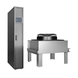
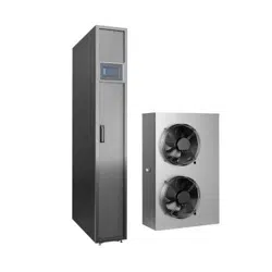
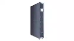
NetCol5000-C(030, 032, 065) In-row
Chilled Water Smart Cooling Product
Quick Guide
Issue: 03
Part Number: 31500CQT
Date: 2021-03-31
1
Copyright © Huawei Technologies Co., Ltd. 2021.
All rights reserved.
1
Overview
Model
NetCol5000
-C030
NetCol5000
-C032
NetCol5000
-C065
Power system
220 V AC to 240 V AC, 1
Ph, 50/60 Hz, dual power supplies
Cooling capacity
30 kW
32 kW
65
kW
Maximum operating
current
9.5 A
9.5 A
15 A
Dimension (mm)
(H x W x D)
2000 x 300 x 1200
2200 x 600 x 1200
2000 x 600 x 1200
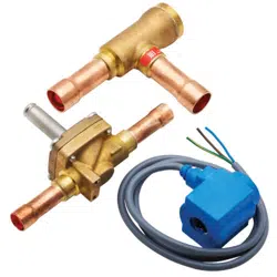
Optional components
Water pump,
wet film humidifier, and micro differential pressure sensor
Note
Top or bottom pipe
routing
Bottom pipe routing only
Top or bottom pipe
routing
The information in this document is subject to change due to version upgrade or other
reasons. Every effort has been made in the preparation of this document to ensure accuracy
of the contents, but all statements, information, and recommendations in this document do
not constitute a warranty of any kind, express or implied.
Only qualified or trained technical personnel are allowed to perform operations on the
device. Operation personnel should understand the composition and working principles of
the smart cooling system and local regulations.
Before installing the device, read the user manual carefully to get familiar with product
information and safety precautions. Huawei shall not be liable for any consequence caused
by violation of the storage, transportation, installation, and operation regulations specified in
this document and the user manual.
Use insulated tools when installing the device. For personal safety, wear proper personal
protective equipment (PPE).
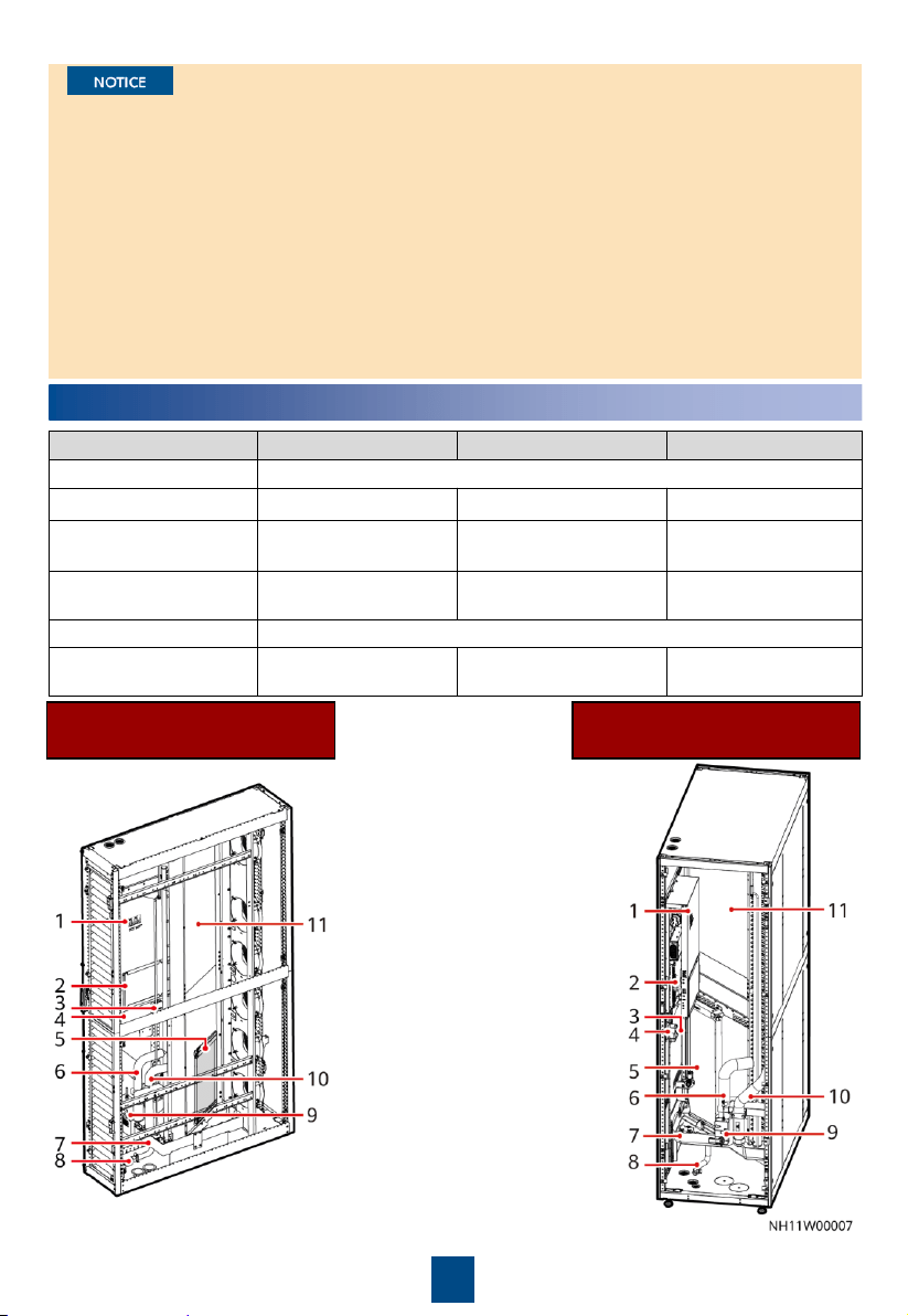
NetCol5000-C030/C032
(Bottom Pipe Routing)
NetCol5000-C065
(Bottom Pipe Routing)
(1) Electric control box
(2) Main control board
(3) Temperature and
humidity
(T/H)
sensor
(4) Differential pressure switch
(5) Wet film humidifier
(6)
Chilled water outlet pipe
(7) Water pan
(8)
Automatic drainpipe
(9) Chilled water valve actuator
(10) Chilled water inlet pipe
(11)
Heat exchanger
2
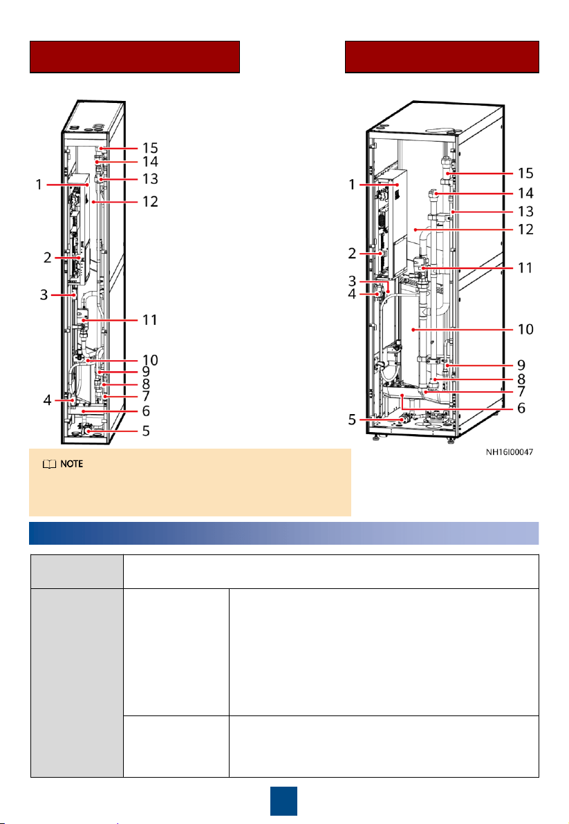
NetCol5000-C030
(Top or Bottom Pipe Routing)
NetCol5000-C065
(Top or Bottom Pipe Routing)
(1) Electric control box
(2) Main control board
(3)
T/H sensor
(4) Differential pressure switch
(5) Water pump
(6) Water pan
(7) Chilled water outlet pipe
(bottom pipe routing)
(8) Chilled water inlet pipe (bottom
pipe routing)
(9) Forcible drainpipe (bottom pipe
routing)
(10) Wet film humidifier
(11) Chilled water valve actuator
(12)
Heat exchanger
(13) Forcible drainpipe (top pipe
routing)
(14) Chilled water inlet pipe
(top pipe routing)
(15) Chilled water outlet pipe (top
pipe routing)
2
Preparing Materials
Materials
Delivered
Obtain the materials listed in the packing list from the accessories delivered
with the product.
Engineering
Procurement
Drainpipe
Choose rigid pipe connection or hose connection based on
the actual application scenario. The NetCol5000
-
C065 (top
or bottom pipe routing) supports only hose connection if
bottom pipe routing is adopted.
BSPT 1/2–inch hose connector with external threads,
and hose (made of EPDM or other materials)
BSPT 1/2-inch rigid pipe connector with external
threads, and rigid pipe (made of PP-R or other
materials)
Humidifier water
inlet pipe
(optional)
Rigid pipe:
G 3/4-inch rigid pipe connector with internal
threads (plastic materials such as PA66,
or metal materials
are recommended), and rigid pipe (withstand pressure ≥
0.7 MPa)
The position of the differential pressure switch is for
reference only. For some models, it is close to the T/H
sensor.
3
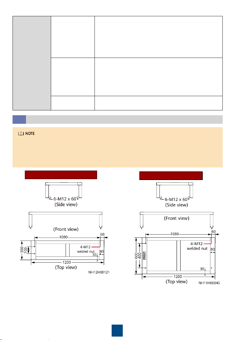
Base
2.1
1. Shock absorption bars (EPDM rubber, 5 mm thick) need to be installed between the
ground and the base.
2. The base should be at least 250 mm in height.
3. You are advised to use angle steel. Thickness of 5 mm is recommended.
Engineering
Procurement
Chilled water inlet
and outlet pipes
NetCol5000
-C030/C032: Seamless steel pipe with a G 1
inch
external threaded connector or aluminum plastic pipe
with an inner diameter of 26 mm (withstand pressure ≥ 1.6
MPa
)
NetCol5000
-C065: Seamless steel pipe with a G 1–1/2 inch
external threaded connector or aluminum plastic pipe with
an inner diameter of 41 mm.
Cables
NetCol5000
-C030/C032: Power cable (3 x 2.5 mm²),
teamwork networking and monitoring cables, and
equipotential cable (≥ 16 mm²
)
NetCol5000
-C065: Power cable (3 x 6.0 mm²), teamwork
networking and monitoring cables, and equipotential cable
(≥ 16 mm²)
Others
Base, thermal insulation foam, and thermal insulation foam
glue
NetCol5000-C065
NetCol5000-C030/C032
Unit: mm
4
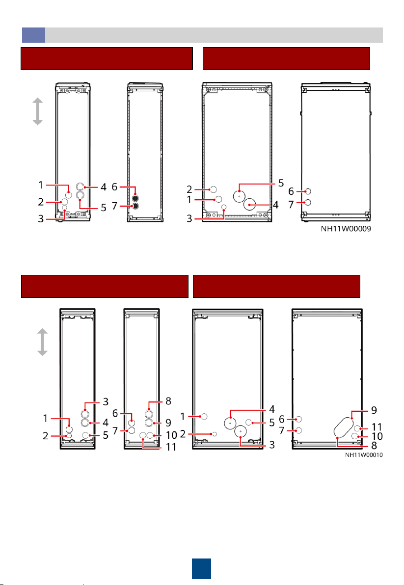
Holes in Top and Bottom Plates
2.2
NetCol5000-C030/C032
(Bottom Pipe Routing)
NetCol5000-C065
(Bottom Pipe Routing)
(1) Drainpipe
hole
(2) Humidifier water inlet pipe hole
(3)
Ground cable hole
(4) Chilled water inlet pipe hole
(5) Chilled water outlet pipe hole
(6) Power cable hole
(7) Signal cable hole
Front
Rear
Bottom
Top
Bottom
Top
NetCol5000-C030
(Top or Bottom Pipe Routing)
NetCol5000-C065
(Top or Bottom Pipe Routing)
(1) Humidifier water inlet pipe
hole (bottom pipe routing)
(2) Ground cable hole
(3) Chilled water inlet pipe
hole (bottom pipe routing)
(4) Chilled water outlet pipe
hole (bottom pipe routing)
(5) Drainpipe hole (bottom
pipe routing)
(6) Power cable hole
(7) Signal cable hole
(8) Chilled water inlet pipe
hole (top pipe routing)
(9) Chilled water outlet pipe
hole (top pipe routing)
(10) Drainpipe hole (top pipe
routing)
(11) Humidifier water inlet
pipe hole (top pipe routing)
Front
Rear
Bottom
Top
Bottom
Top
5
3
Installing the Equipment
1. The unit in this document is a fully configured NetCol5000-C. If some components are not
configured, skip the corresponding steps.
2. You are recommended to use tools that are fully insulated when installing devices.
3. Only qualified or trained technical personnel are allowed to install, commission, and maintain
smart cooling products. Otherwise, personal injuries and device damage may be caused,
which is beyond the smart cooling product warranty range.
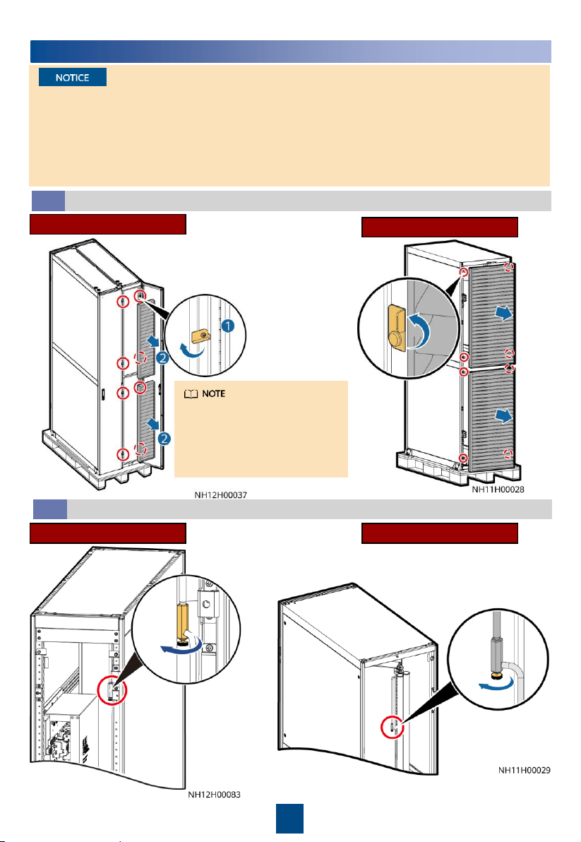
Removing Air Filters
3.1
For single-cabinet and dual-
cabinet packaging, the methods
for removing air filters are the
same. Take dual-cabinet
packaging as an example.
NetCol5000-C030/C032
NetCol5000-C065
Discharging Nitrogen
3.2
Slowly open the exhaust
valve to release nitrogen and
close the valve afterwards.
NetCol5000-C065NetCol5000-C030/C032

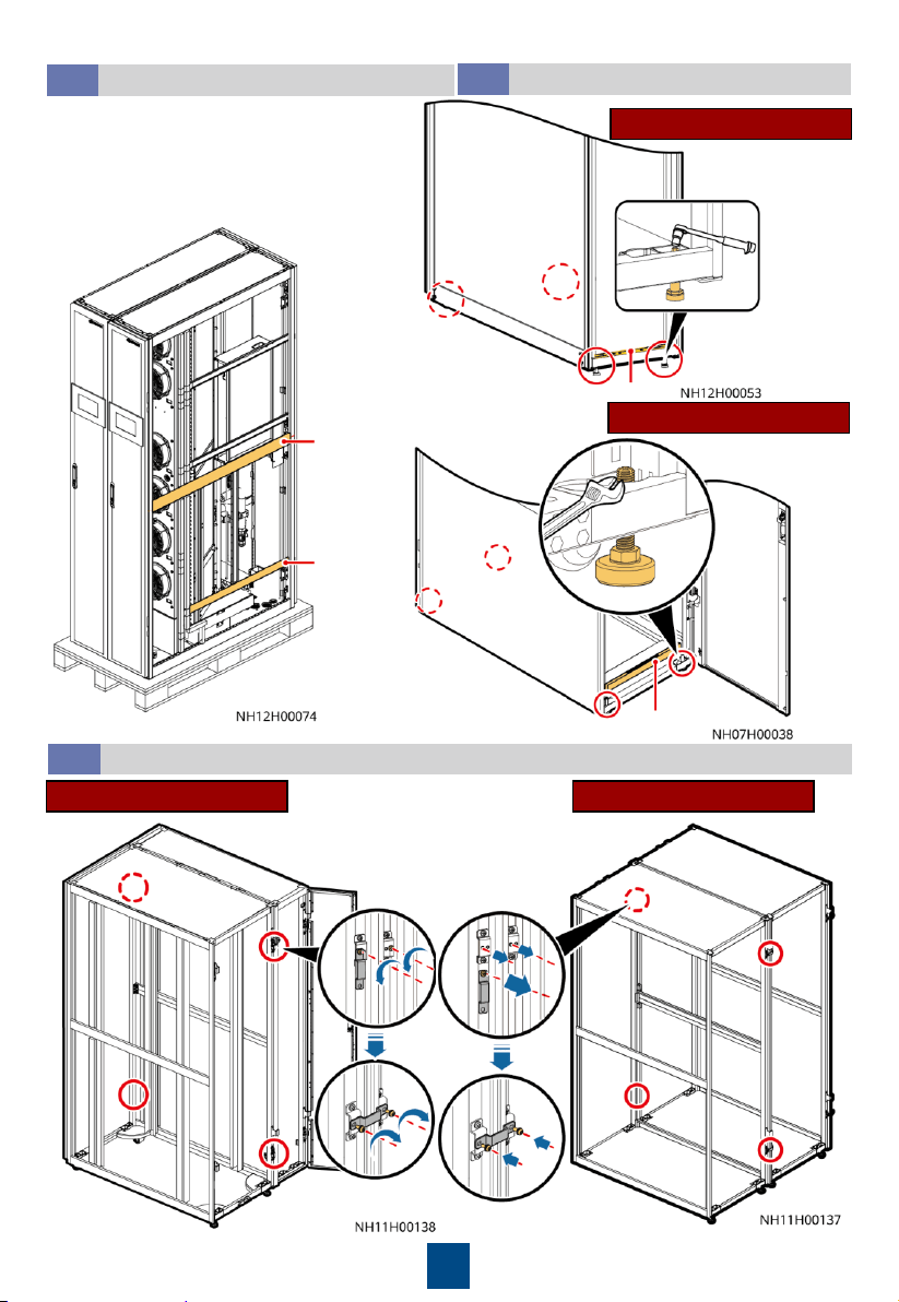
6
Removing the Pallet
3.3
NetCol5000-C065NetCol5000-C030/C032
The connectors are secured to the
equipment with M6 screws and secured
to the pallet with M12 screws.
(Dual-cabinet packaging)
1. The equipment has been injected with 0.2–0.6 MPa of nitrogen before delivery. If no nitrogen
is discharged, contact Huawei technical support.
2. You can open or close the exhaust valve using a flat-head screwdriver.
(Single-cabinet packaging)
(Optional) Removing
Side Plates
3.4
This section only
applies to the
NetCol5000-
C030/032.
7
(Optional) Moving the Cabinet
3.5
Force-
bearing
beam
Force-
bearing
beam
Four to six persons are required to move
the cabinet to the installation position.
After that, install the side plates.
Leveling the Cabinet
3.6
Level
NetCol5000-C065
Level
NetCol5000-C030/C032
This section only applies to the
NetCol5000-C030/032.
Combining Cabinets
3.7
NetCol5000-C065NetCol5000-C030/C032
8
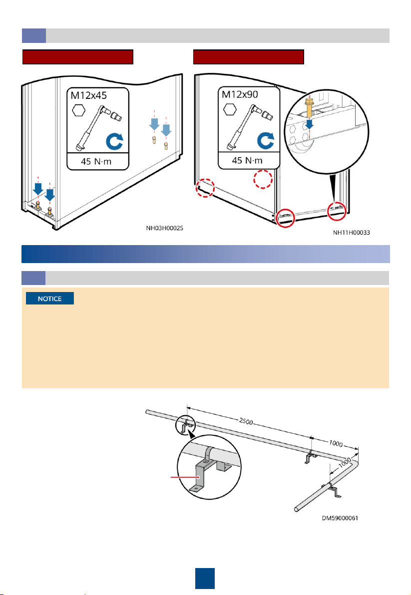
Securing the Equipment
3.8
NetCol5000-C065NetCol5000-C030/C032
Unit: mm
Pipe support
4
Installing Pipes
1. A 1:100 tilt should be reserved for the main drainpipe and humidifier water inlet pipe.
2. Keep a clearance of at least 25 mm between pipes. Secure the pipes to supports every a
certain distance.
3. Clean the water inlet engineering pipes to avoid impurities entering into the humidifier.
4. A reducing valve must be installed if the inlet water pressure exceeds 0.7 MPa.
5. Pipes should be wrapped with thermal insulation foam along the route.
6. When routing pipes from the top, take protective measures to prevent pipe leakage from
affecting servers or other devices.
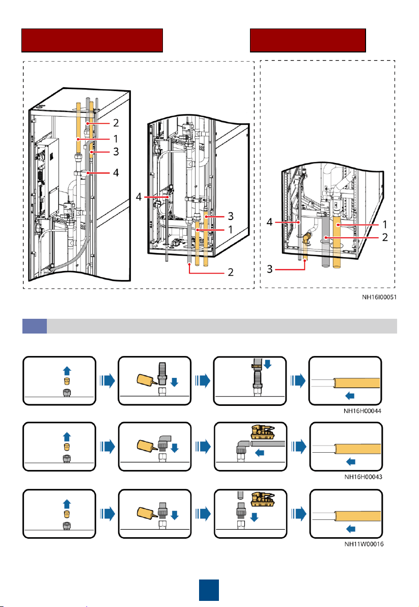
Pipe Layout
4.1
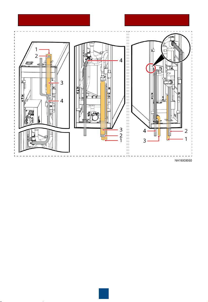
9
NetCol5000-C030
Top or Bottom Pipe Routing
NetCol5000-C030/C032
Top Pipe Routing
Top pipe routing Bottom pipe routing
Bottom pipe
routing
(1) Chilled water inlet pipe
(2) Chilled water outlet pipe
(3) Drainpipe
(4) Humidifier water inlet pipe
10
Installing a Drainpipe
4.2
NetCol5000-C065
Top or Bottom Pipe Routing
NetCol5000-C065
Bottom Pipe Routing
Top pipe routing Bottom pipe routing Bottom pipe routing
(1) Chilled water inlet pipe
(2) Chilled water outlet pipe
(3) Drainpipe
(4) Humidifier water inlet pipe
Thermal insulation foam:
thickness ≥ 9.2 mm
Hose connection:
Rigid pipe connection (automatic drainage):
Rigid pipe connection (forcible drainage):
11
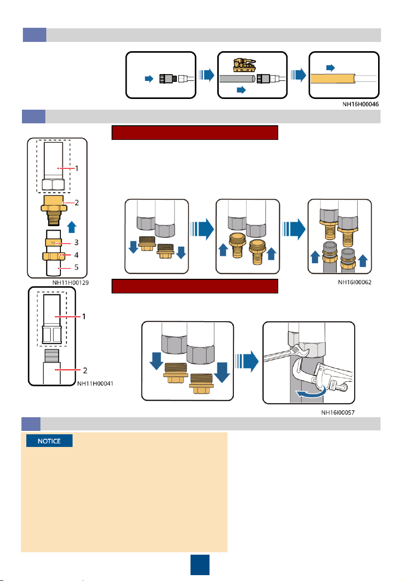
Installing Chilled Water Inlet and Outlet Pipes
4.4
(1) G 1
–1/2 inch inner thread connector (reserved)
(2) Straight male connector
(3) Gasket
(4) Nut
(5) Aluminum
-plastic pipe with an inner diameter of 41 mm
(1) G 1
–1/2 inch inner thread connector (reserved)
(2) G 1
–1/2 inch seamless steel pipe with external threads
1. Connect pipes.
2. Wrap the pipes with thermal insulation foam.
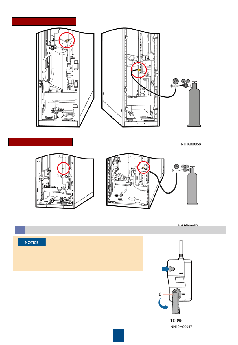
(
Optional) Leakage Test with Nitrogen
4.5
If the pressure has fallen, apply soapy water on the
pipes, especially at pipe joints, to check for
leakages. Rectify the leakages if any.
If the pressure is stable, wrap all pipes and
connectors with thermal insulation foam.
Install a reducing valve on the outlet of the
nitrogen cylinder. Its outlet pressure must not
exceed 0.8 MPa.
In addition to the leakage test with nitrogen, there
is the leakage test with water. You can choose one
test based on site requirements.
1. Rotate the chilled water valve to
the maximum (100%).
2. Check that the needle and exhaust
valves on the pipeline are closed.
3. Connect a reducing valve and a
nitrogen cylinder at the needle
valve position shown in the figure,
charge 0.8 MPa of nitrogen (when
the pressure is stable), and leave
them for 24 hours.
4. Check for pressure change after 24
hours.
Aluminum-plastic pipe connection
Seamless steel pipe connection
Installing a Humidifier Water Inlet Pipe
4.2
Clean the engineering
pipe, connect the
reserved humidifier
water inlet pipe to the
engineering pipe, and
wrap the pipe with
thermal insulation foam.
12
Top or bottom pipe routing Bottom pipe routing
NetCol5000-C065
NetCol5000-C030/C032
Injecting Water to Expel Nitrogen
4.6
Clean the main pipe beforehand to avoid blockage of the
heat exchanger due to foreign construction matter. Close
the isolation valve on the water inlet and outlet pipes
before the cleaning.
1. Open the general water supply valve.
2. Press the button on the side of the actuator and
manually rotate the valve handle to the maximum in
the specified direction. Check that the chilled water
valve is in the open state (100%).
3. Slowly open the exhaust valve to let out gas.
4. Adjust the gas releasing speed until no gas flows out
of the valve. Then close the exhaust valve.
5. Manually close the chilled water valve.
Top or bottom pipe routing Bottom pipe routing
13
(Optional) Leakage Test with Water
4.7
Manually open the chilled water valve. Inject water to 0.8 MPa,
and preserve the pressure for 24 hours. Then connect a pressure
gauge to a needle valve on the pipeline to measure the
pressure. If the reading remains unchanged, the pipe is not
leaking. You can perform the following operations.
If the leakage test has been
done with nitrogen, skip the
test with water.
5
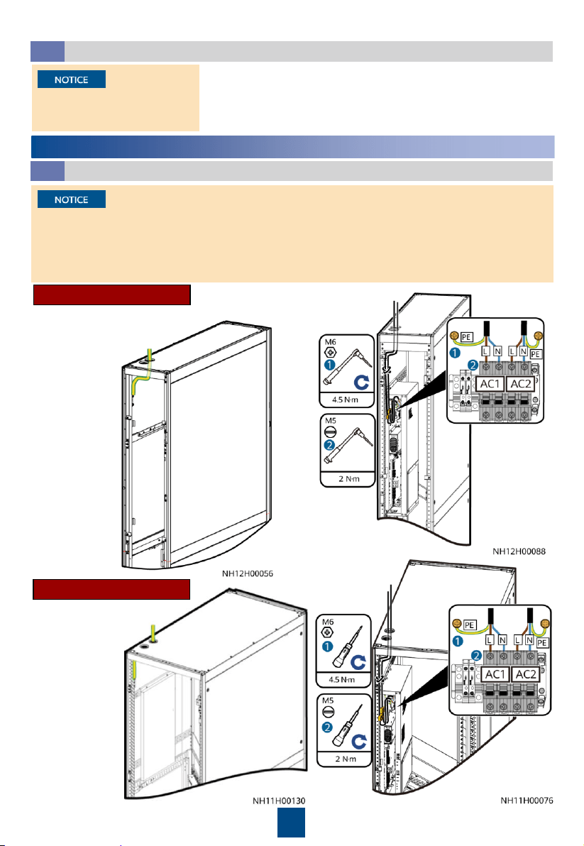
Installing Cables
Connecting the Equipotential Ground Cable and Power Cable
5.1
1. When routing the cables, wrap the section of all signal cables inside the smart cooling
product with the corrugated pipes and route them out of the corresponding cable holes so
that the electric and ELV cables are separated.
2. Route the power cable along the rear door post, and use cable ties to secure the cable to the
post every 150–200 mm.
NetCol5000-C065
NetCol5000-C030/C032
1. Connect the equipotential
cable.
2. Connect the
power cable.
1. Connect the equipotential cable.
2. Connect the
power cable.
14
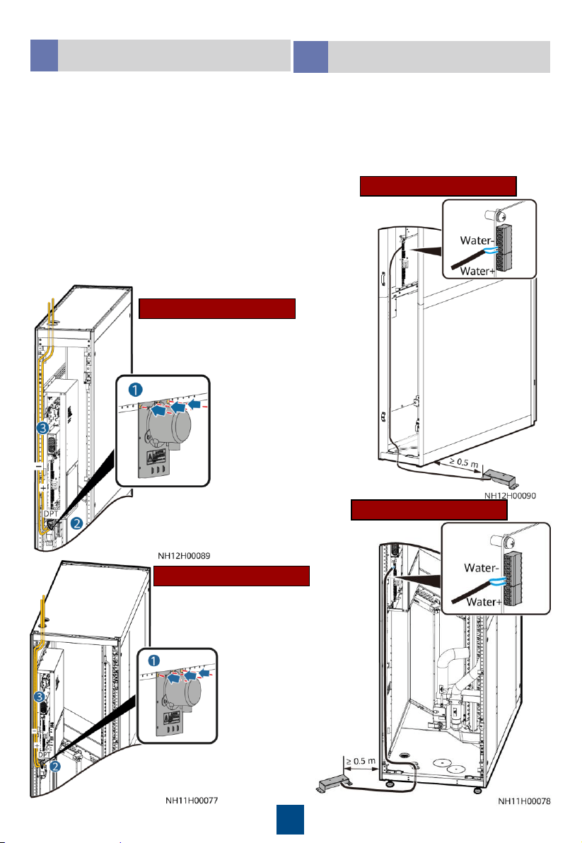
(Optional) Installing a Micro
Differential Pressure Sensor
5.2
(Optional) Connecting a Water
Sensor
5.3
NetCol5000-C065
NetCol5000-C030/C032
Connect a pressure inlet tube to the + mark and
route it to the aisle through the hole on the top
of the cabinet. Ensure that the pressure inlet
faces downwards. Connect another pressure
inlet tube to the – mark and route it to the
cabinet top through the hole atop.
Connect the cable terminal of the micro
differential pressure sensor to the DPT terminal.
Connect a pressure inlet tube to the + mark and route it
to the cabinet top through the hole atop. Connect
another pressure inlet tube to the – mark and route it to
the aisle through the hole on the top of the cabinet.
Ensure that the pressure inlet faces downwards.
NetCol5000-C065
NetCol5000-C030/C032
Cold aisle
Hot aisle
A water sensor monitors resistance changes
at terminals to determine whether the floor is
watery. When the terminals of a water sensor
detect water or other conductive liquid,
resistance between the two terminals
decreases. Keep water sensors far away from
water traps or floor drains.
15
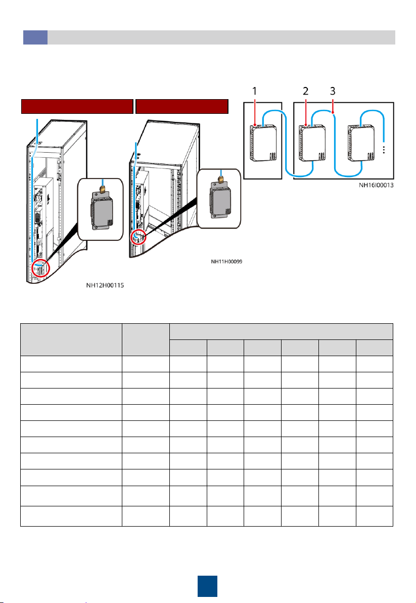
NetCol5000-C065NetCol5000-C030/C032
1. Connect T/H sensor cables.
2. Set the DIP switches on the T/H sensors.
(Optional) Installing T/H Sensors Outside Cabinets
5.4
T/H sensors in the aisle should be installed at the door frame inside the IT cabinet and 1.5 m
above the ground (33 U). After they are secured, set the sensor positions based on their
locations and the table.
Name Address
DIP Switch ID
1 2 3 4 5 6
Cold aisle 1 temp/humid 11 ON ON OFF ON OFF OFF
Cold aisle 2 temp/humid 12 OFF OFF ON ON OFF OFF
Cold aisle 3 temp/humid 13 ON OFF ON ON OFF OFF
Cold aisle 4 temp/humid 14 OFF ON ON ON OFF OFF
Cold aisle 5 temp/humid 15 ON ON ON ON OFF OFF
Hot aisle 1 temp/humid 21 ON OFF ON OFF ON OFF
Hot aisle 2 temp/humid 22 OFF ON ON OFF ON OFF
Hot aisle 3 temp/humid 23 ON ON ON OFF ON OFF
Hot aisle 4 temp/humid
24
OFF OFF OFF ON ON OFF
Hot aisle 5 temp/humid
25
ON OFF OFF ON ON OFF
(1)
NetCol5000-C T/H sensor
(2) IT cabinet T/H sensor
(3)
Standard network cable
16
(Optional) Connecting the Teamwork Network Cable
5.5
Connecting an FE Teamwork Network Cable
The smart cooling product supports both FE teamwork networking and CAN teamwork
networking (hand-in-hand).
All smart cooling products in a teamwork group must be of the same model.
Do not directly connect the first and the last smart cooling products to form a ring network.
A maximum of 32 smart cooling products can be networked in one group. The teamwork
cable between two adjacent smart cooling products must not exceed 10 m.
If CAN networking is required onsite, choose Teamwork Settings and set Enable teamwork
CAN resistor for the first and last smart cooling products to Yes on the screen.
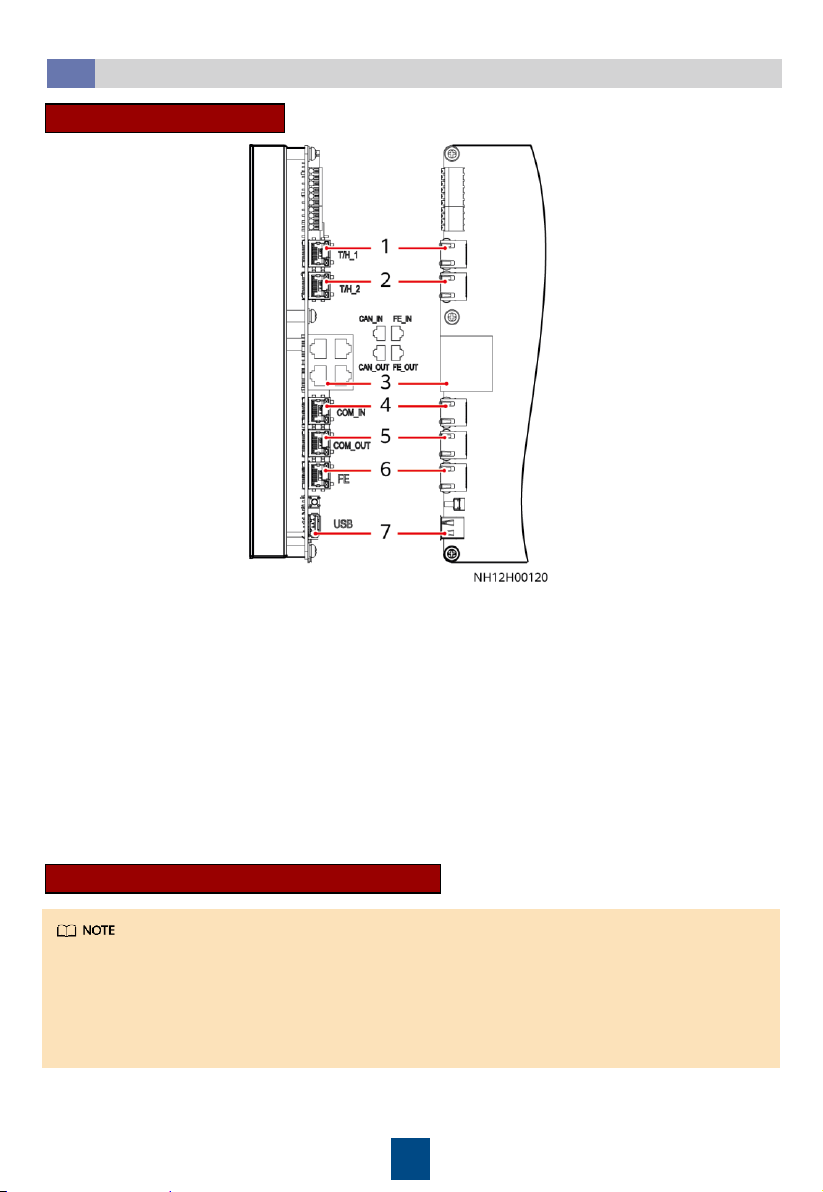
(1) T/H_1 (T/H RS485 communications port) (used for connecting to the external
T/H sensor)
(2) T/H_2 (T/H RS485 communications port) (used for connecting to the external
T/H sensor)
(3) CAN_IN/CAN_OUT/FE_IN/FE_OUT (used for teamwork
networking)
(4)
COM_IN (RS485 communications port) (used for connecting to the monitoring system)
(5)
COM_OUT (RS485 communications port) (used for connecting to the monitoring system)
(6) FE (used for connecting to the monitoring system)
(7) USB
Main Control Board Ports
17
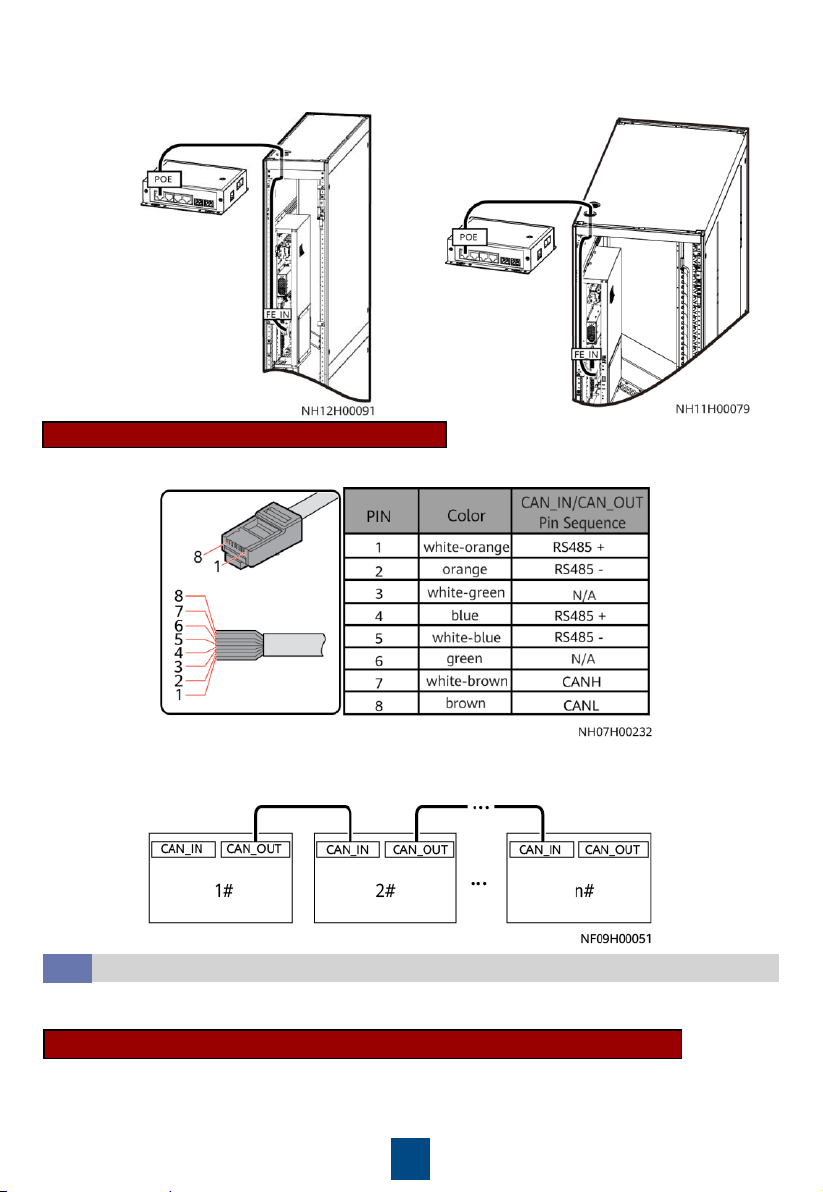
NetCol5000-C065
NetCol5000-C030/C032
CAN Teamwork Networking Cable
1. Prepare an 8-pin standard network cable. The cable pin sequence requirements are shown below.
2. Connect the CAN_OUT port of each smart cooling product to the CAN_IN port of the following
smart cooling product using a CAN network cable. After powering on the device, set Enable
teamwork CAN resistor to Yes for the first and last devices in a teamwork group.
Connecting the FE monitoring Cable (SNMP/Modbus-TCP Protocol)
(Optional) Connecting the Monitoring Network Cable
5.6
The smart cooling product supports both RS485 monitoring and FE monitoring.
Modbus-TCP (connecting to the smart ETH gateway): The same network cable is used for FE
monitoring and FE teamwork control.
SNMP: Connect the FE monitoring network cable to the FE port.
Connect one end of the FE network cable to the FE_IN port on the main control module, and
connect the other end to the POE port on the smart ETH gateway.
18
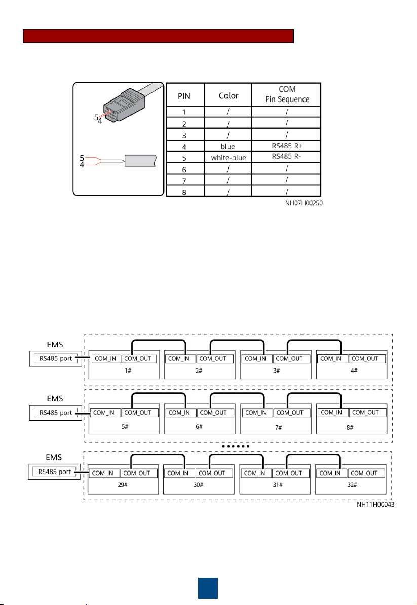
RS485 Monitoring Network Cable (Modbus-RTU Protocol)
1. Make the COM network cable by referring to the following figure.
If there is no teamwork control, connect the COM_IN port on each smart cooling product to
the customer's monitoring system.
2. Group smart cooling products for monitoring based on performance requirements and
connect the monitoring network cables.
In CAN networking, connect the COM_IN port on the first smart cooling product in each
monitoring group to the monitoring device.
19
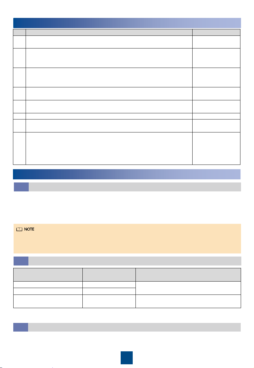
6
Verifying the Installation
No.
Check Item
Check Result
1
All water pipes are properly and securely installed, and free from
leakage, blockage, and sharp turns.
□
Passed
□
Failed
2
The liquid level detector is level. The water pan is free from foreign
matter such as cable remains and thermal insulation foam. Cables are
securely bound and not in the water pan.
□
Passed □ Failed
3
The distance between two chilled water pipes outside the cabinet is
sufficient (recommended distance: longer than 25 mm), the hose is
tightly wrapped with insulation foam, and joints are secured using glue.
□
Passed
□
Failed
4
The pipeline system has passed the pressure preservation and air
tightness tests.
□
Passed
□
Failed
5
The needle valve plugs are secured (torque of
0.45
±
0.05 N•m), and
screw caps are tightened.
□
Passed
□
Failed
6
The cabinet is reliably grounded.
□
Passed □ Failed
7
The power cables and signal cables are correctly connected and
properly separated.
Electric and ELV cables are separately bound.
□
Passed
□
Failed
8
The chilled water valve and its actuator are securely installed.
The
chilled water connector joints have been wrapped with thermal
insulation foam, and no metal or hose is exposed. Cables are securely
connected to the chilled water valve actuator. The actuator manual
button is reset (ejected state).
□
Passed □ Failed
7
System Power-On
1. Turn on the smart cooling product switch in the power distribution cabinet and the AC1 and AC2
switches on the smart cooling product.
2. After the device is powered on for the first time, the LCD displays the Quick Settings screen. Set
parameters as instructed, such as language, date format, date, time, and time zone. If the device
is not powered on for the first time, the home screen is displayed.
Users are classified into admin and operator. The preset password is 000001 for both types of
users.
After powering on, the smart cooling product is in shutdown mode.
Power-On
7.1
If a T/H sensor outside the cabinet is installed, enable it. Path: Settings > System Settings >
Common Settings or Settings > System Settings > T/H Sensor
(Optional) Enabling the T/H Sensor Outside the Cabinet
7.3
(Optional) Setting the T/H Control Type
7.2
Application Scenario
Recommended T/H
Control Type
Remarks
Cold aisle containment Cold aisle control
If cold aisle T/H sensors are not configured,
you can also choose the supply air control.
Hot aisle containment Cold aisle control
Non-aisle containment Return air control
If cold aisle T/H sensors are configured,
you can also choose the cold aisle control.
Path: Settings > System Settings > Common Settings or Settings > System Settings > T/H
Sensor
20
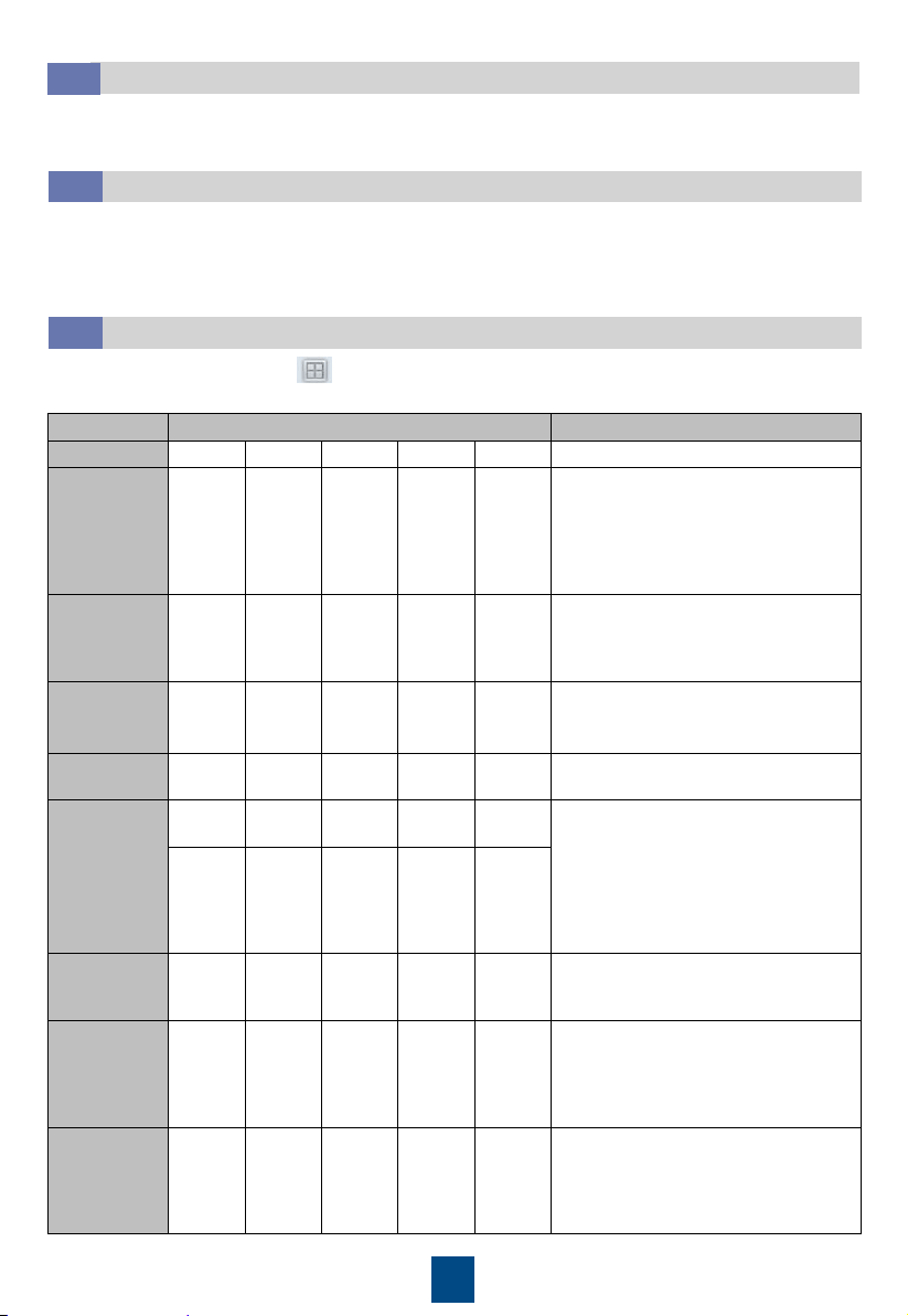
(Optional) Teamwork Settings
7.6
(Optional) Setting the Indoor Fan Control Type
7.5
If a micro differential pressure sensor is installed and the pressure difference control is required,
set Air-side difference pressure sensor type to 0–50 Pa, and set Indoor fan control type to
Pressure diff ctrl. It is recommended that the default value be retained for Indoor fan pressure
difference setpoint. If there are hot spots onsite, you can increase the value. Path: Settings >
System Settings > Indoor fan
Temperature and Humidity Settings
7.4
Set Temperature and humidity control type, Control point temperature setpoint, and
Control point humidity setpoint as required on site. Path: Settings > System Settings >
Common Settings or Settings > System Settings > T/H Sensor
On the home screen, choose > Teamwork Settings. The following uses a teamwork group
consisting of eight devices as an example.
Item
Setting Setting Rule
No.
1 2 ... 7 8
Smart cooling product No.
Teamwork
group No.
1 1 ... 1 1
A teamwork network can contain a
maximum of four groups, which can
be numbered 1 to 4 respectively.
Smart cooling products in a group
must have the same teamwork group
number.
System
address
1 2 … 7 8
In a teamwork group, the address (1–
32) of each unit must be unique and
the unit with the smallest address is
the master unit.
Enable
teamwork
CAN resistor
Yes No ... No Yes
This parameter needs to be set in
CAN networking. Set it to
Yes
for the
first and last units.
Teamwork
function
Enable Enable ... Enable Enable
/
Networking
mode
CAN
network
CAN
network
…
CAN
network
CAN
network
The networking mode selected on
the screen must be consistent with
the actual networking mode
.
The MAC_CAN network and FE
network are the same teamwork
networking mode. The displayed
value prevails.
MAC_CA
N
network
or FE
network
MAC_CA
N
network
or FE
network
…
MAC_CA
N
network
or FE
network
MAC_CA
N
network
or FE
network
Number of
systems in
this group
8 / ... / /
The value ranges from 1 to 32.
Number of
running
systems in
this group
6 / ... / /
The value ranges from 1 to the
number of units in the group. Except
the
running units
in the group, other
units in the group are used as
standby units.
Rotation
function
Enable / … / /
When the rotation function is
enabled, the
running and standby
units can work alternately. It is
recommended that the function be
enabled when the load is even.
21
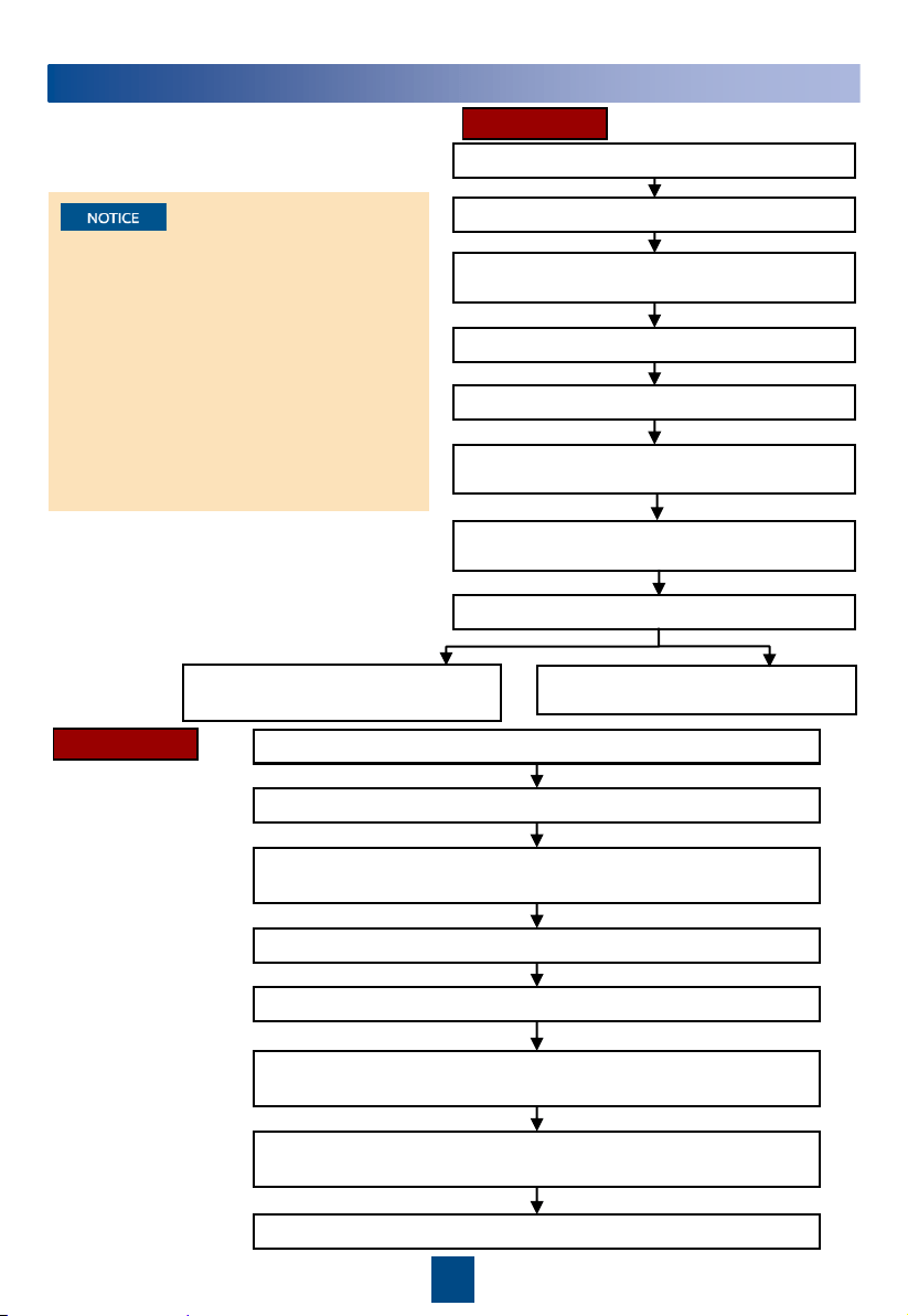
8
Startup and Wizard Startup
1. First startup flowchart
Download the Service Expert app from
HUAWEI AppGallery. The app can only
run on Android currently. You must
apply for the permission to use the app
after downloading it.
If this is not the first startup, choose
Maint > Wizard Startup to enter
wizard startup.
If no humidifier is configured, its
commissioning item is not displayed.
Open the Service Expert app and tap StartUp.
Choose Link, and enter the IP address, port number, username,
password, and device address. Tap Login.
Choose Settings > Comm Settings > WIFI Settings on the home
screen and set the WiFi password.
Start
Insert the WiFi module to the USB port on the main control board
Tap Power-on password activation. A message is displayed, asking
you whether to star the device.
The device is started after you tap OK.
Connect the mobile phone to the WiFi network.
Offline Boot
Offline Boot or Online Boot can be selected
for the first startup.
Online Boot
Open the Service Expert app.
Tap Startup > Offline Activation on the app.
After tapping Yes, the barcode and the
verification code are shown on the screen.
Tap Start on the home screen.
Enter Bar code and Verification code, and tap
Generate PWD.
Enter the generated startup password on the
screen of the smart cooling product.
Tap No on the Wizard Startup
screen to exit wizard startup.
Tap Enter. The screen turns to Wizard Startup.
Tap Yes on the Wizard Startup
screen to enter wizard startup.
Start
22
9
Checking After Commissioning
Check Item
Result
The controller exits diagnostic mode.
□
Passed
□
Failed
The temperature and humidity are correctly set.
□
Passed
□
Failed
The
chilled water valve is closed.
□
Passed
□
Failed
10
Power-Off
1. Tap Shutdown on the LCD home screen.
2. Turn off all switches of the smart cooling product.
3. If the smart cooling product will not be used over a long time, drain the water in the
heat exchanger or take antifreeze measures to avoid frost cracks.
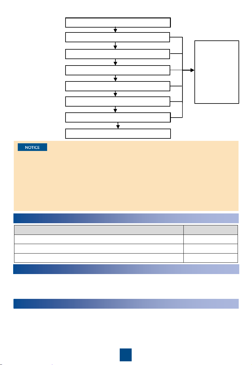
2. Wizard startup
flowchart
Fail
Chilled water valve commissioning
Humidifier commissioning
Indoor fan commissioning
Commissioning
interrupted
(Handle the fault
by referring to
the tips displayed
on the home
screen. Perform
wizard startup
after the
handling.)
Start
Succeed
Succeed
Succeed
Drainage pump commissioning
Select commissioning items
Yes
No
No
Fail
Confirm precautions and check items
Fail
If the floor water overflow alarm is generated, the smart cooling product will shut down by
default. If you do not need to stop the smart cooling product, contact Huawei technical
support engineers to evaluate the risk. After the risk is evaluated, choose Settings > System
Settings > System Control, and set the Water overflow alarm action to Inactivity or Only
indoor fan running or Humidification stopped.
If the in-cabinet water overflow alarm is generated, the humidifier will stop by default. If you
do not need to stop the humidifier, contact Huawei technical support engineers to evaluate
the risk. After the risk is accepted, choose Settings > System Settings > System Control,
and set the Water overflow alarm action to No action or Only the indoor fan running or
Shutdown.
Appendix: Precautions for Adding Glycol
To prevent glycol solution from corroding pipes and the heat exchanging coil, corrosion inhibitor
should be mixed into the glycol solution. For details about the mixing schemes, consult glycol
experts.
Huawei Technologies Co., Ltd.
Huawei Industrial Base, Bantian, Longgang
Shenzhen 518129 People's Republic of China
www.huawei.com
End
Succeed
Fail