Loading ...
Loading ...
Loading ...
11
-
DIM ON
page 7
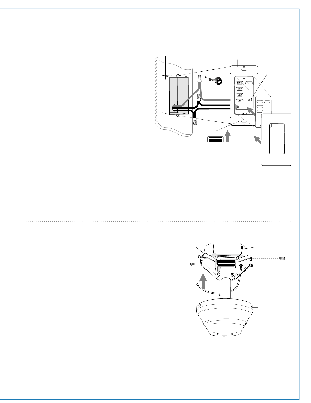
7. Canopy Assembly.
Raise canopy to hanging bracket and align slotted
holes in canopy with loosened screws in hanging
bracket. Twist canopy to lock. Re-insert screws (along
with star washers) that were previously removed
(page 4, Section 4) and secure all screws with a
Phillips screwdriver.
*Remember that antenna for remote control receiver
must rest outside of hanging bracket.
canopy
hanging
bracket
slotted hole
antenna
6. Wiring. (cont.)
[PLEASE NOTE: Wall and/or handheld remote
control must be used for fan to operate. If you do
not wish to use the wall control, please proceed to
Section 7 below to continue with fan installation.]
To install wall control, remove existing wall switch.
Wire one of the wall controls with wire connectors
provided as shown in diagram at right.
*Wrap each wire connector separately with
electrical tape as an extra safety measure. Gently
push wires and taped wire connectors into outlet
box.
Install one 12-volt battery (included) in wall control.
IMPORTANT: Wall control will not function unless
battery is installed.
Since this fan comes with an incandescent bulb, the
dimmer switch (labeled DIM and ON) has been
pre-set to the "ON" position (DIM). If you do not
wish to have dimming capability, please move the
switch to the "OFF" position (ON).
Select a faceplate (almond or white) and press
firmly onto front of wall control. Attach wall control
to outlet box and secure with screws from original
wall switch. Attach plate (included) to wall control
using 2 screws provided with the wall control.
(wiring for wall control)
black (OUT to fan)
green
black
(AC IN from
breaker box)
black
(TO POWER supply)
black
green/
green/
bare
bare
ground
ground
green/
bare
ground
outlet box
wall
control
faceplate
12V battery
dimmer
switch
plate
Loading ...
Loading ...
Loading ...