TVNO30SS395
TVNO36SS395
Installation Instructions
Use and Care Information
Instructions d'installation
Utilisez et d'entretien
Instrucciones de instalación
Información de uso y cuidado
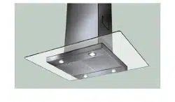
TIVANO

2
CONTENTS
Section Page
Important safety instructions 3
Range Hood dimensions 6
Installation height requirements 7
Parts 8
Tools needed 9
Before Installation Remove Shipping Materials 10
Only for canadian market 11
Choose Vertical or Horizontal Electrical Connection Knockout's
Choose Vertical or Horizontal Electrical Connection Knockout's 12
Ducted venting method options 14
Ducted - 7" round outlet 15
Ducted - 3 1/4" x 10" Rectangular Outlet on top
17
Ducted - 3 1/4" x 10" Rectangular Outlet rear
18
Choosing the Mounting Method
19
Mounting Range Hood on wall
20
Mounting Range Hood under the cabinet
24
Connecting electricity
26
Operating the controls
27
&DULQJIRU´OWHUV
28
Replacing lighting
29
Wiring diagram
30
Warranty
31

3
IMPORTANT SAFETY INSTRUCTIONS
READ AND SAVE THESE INSTRUCTIONS BEFORE YOU START
INSTALLING THIS RANGE HOOD
WARNING: - TO REDUCE THE RISK OF A RANGE TOP GREASE FIRE:
a) Never leave surface units unattended at high settings. Boilovers cause smoking and
greasy spillovers that may ignite. Heat oils slowly on low or medium setting.
E$OZD\VWXUQKRRG21ZKHQFRRNLQJDWKLJKKHDWRUZKHQµDPEHLQJIRRGLH&UHSHV
Suzette, Cherries Jubilee, Peppercorn Beef Flambé).
c) Clean ventilating fans frequently. Grease should not be allowed to accumulate on fan or
´OWHU
d) Use proper pan size. Always use cookware appropriate for the size of the surface element.
WARNING: - TO REDUCE THE RISK OF INJURY TO PERSONS IN THE EVENT OF A RANGE
TOP GREASE FIRE, OBSERVE THE FOLLOWING*:
D6027+(5)/$0(6ZLWKDFORVH´WWLQJOLGFRRNLHVKHHWRUPHWDOWUD\WKHQWXUQRIIWKH
EXUQHU%(&$5()8/7235(9(17%8516,IWKHµDPHVGRQRWJRRXWLPPHGLDWHO\
EVACUATE AND CALL THE FIRE DEPARTMENT.
b) NEVER PICK UP A FLAMING PAN - You may be burned.
c) DO NOT USE WATER, including wet dishcloths or towels - a violent steam explosion will
result.
d) Use an extinguisher ONLY if:
1. You know you have a Class ABC extinguisher, and you already know how to operate
it.
7KH´UHLVVPDOODQGFRQWDLQHGLQWKHDUHDZKHUHLWVWDUWHG
7KH´UHGHSDUWPHQWLVEHLQJFDOOHG
<RXFDQ´JKWWKH´UHZLWK\RXUEDFNWRDQH[LW
* Based on "Kitchen Firesafety Tips" published by NFPA
WARNING - TO REDUCE THE RISK OF FIRE OR ELECTRIC SHOCK, do not use this fan with
any solid-state speed control device.
WARNING - TO REDUCE THE RISK OF FIRE, ELECTRICAL SHOCK, OR INJURY TO PERSONS,
OBSERVE THE FOLLOWING:
1. Use this unit only in the manner intended by the manufacturer. If you have any questions,
contact the manufacturer.
2. Before servicing or cleaning unit, switch power off at service panel and lock the service
disconnecting means to prevent power from being switched on accidentally. When the
service disconnecting means cannot be locked, securely fasten a prominent warning
device, such as a tag, to the service panel.
CAUTION: For General Ventilating Use Only. Do Not Use To Exhaust Hazardous or Explo-
sive Materials and Vapors.
WARNING - TO REDUCE THE RISK OF FIRE, ELECTRICAL SHOCK, OR INJURY TO PERSONS,
OBSERVE THE FOLLOWING:
1. ,QVWDOODWLRQ:RUN$QG(OHFWULFDO:LULQJ0XVW%H'RQH%\4XDOL´HG3HUVRQV,Q$FFRU-
dance With All Applicable Codes And Standards, Including Fire-Rated Construction.
2. 6XI´FLHQWDLULVQHHGHGIRUSURSHUFRPEXVWLRQDQGH[KDXVWLQJRIJDVHVWKURXJKWKH
µXHFKLPQH\RIIXHOEXUQLQJHTXLSPHQWWRSUHYHQWEDFNGUDIWLQJ)ROORZWKHKHDWLQJ
equipment manufacturer's guideline and safety standards such as those published by
WKH1DWLRQDO)LUH3URWHFWLRQ$VVRFLDWLRQ1)3$DQGWKH$PHULFDQ6RFLHW\IRU+HDWLQJ
5HIULJHUDWLRQDQG$LU&RQGLWLRQLQJ(QJLQHHUV$6+5$(DQGWKHORFDOFRGHDXWKRULWLHV
4
ALL WALL AND FLOOR OPENINGS WHERE THE RANGE HOOD IS INSTALLED
MUST BE SEALED.
This Range Hood requires at least 24" of clearance between the bottom of the Range
Hood and the cooking surface or countertop. This hood has been approved by UL at this
distance from the cooktop.
This minimum clearance may be higher depending on local building codes. For gas cooktops
and combination ranges, a minimum of 30" is recommended and may be required.
Overhead cabinets on both sides of this unit must be a minimum of 18" above the cooking
surface or countertop. Consult the cooktop or range installation instructions given by the
manufacturer before making any cutouts.
MOBILE HOME INSTALLATION The installation of this Range Hood must conform to the
Manufactured Home Construction and Safety Standards, Title 24 CFR, Part 3280 (formerly
Federal Standard for Mobile Home Construction and Safety, Title 24, HUD, Part 280). See
Electrical Requirements"
• Venting system MUST terminate outside the home.
• DO NOT terminate the ductwork in an attic or other enclosed space.
• DO NOT use 4" laundry-type wall caps.
• Flexible-type ductwork is not recommended.
• DO NOTREVWUXFWWKHµRZRIFRPEXVWLRQDQGYHQWLODWLRQDLU
)DLOXUHWRIROORZYHQWLQJUHTXLUHPHQWVPD\UHVXOWLQD´UH
WARNING
!
VENTING REQUIREMENTS
Determine which venting method is best for your application. Ductwork can extend either
through the wall or the roof.
The length of the ductwork and the number of elbows should be kept to a minimum to
SURYLGHHI´FLHQWSHUIRUPDQFH7KHVL]HRIWKHGXFWZRUNVKRXOGEHXQLIRUP'RQRWLQVWDOO
two elbows together. Use duct tape to seal all joints in the ductwork system. Use caulking
WRVHDOH[WHULRUZDOORUµRRURSHQLQJDURXQGWKHFDS
Flexible ductwork is not recommended. Flexible ductwork creates back pressure and air
turbulence that greatly reduces performance.
0DNHVXUHWKHUHLVSURSHUFOHDUDQFHZLWKLQWKHZDOORUµRRUIRUH[KDXVWGXFWEHIRUHPDNLQJ
cutouts. Do not cut a joist or stud unless absolutely necessary. If a joist or stud must be cut,
then a supporting frame must be constructed.
WARNING - To Reduce The Risk Of Fire, Use Only Metal Ductwork.
&$87,217RUHGXFHULVNRI´UHDQGWRSURSHUO\H[KDXVWDLUEHVXUHWRGXFWDLURXWVLGH
– Do not vent exhaust air into spaces within walls or ceilings or into attics, crawl spaces,
or garages.
Cold Weather installations
$QDGGLWLRQDOEDFNGUDIWGDPSHUVKRXOGEHLQVWDOOHGWRPLQLPL]HEDFNZDUGFROGDLUµRZDQGDQRQPH-
tallic thermal break should be installed to minimize conduction of outside temperatures as part of the
vent system. The damper should be on the cold air side of the thermal break. The break should be as
close as possible to where the vent system enters the heated portion of the house.
3. When cutting or drilling into wall or ceiling, do not damage electrical wiring and other
hidden utilities.
4. Ducted fans must always be vented to the outdoors.
5
ELECTRICAL REQUIREMENTS
A 120 volt, 60 Hz AC-only electrical supply is required on a separate 15 amp fused circuit.
A time-delay fuse or circuit breaker is recommended. The fuse must be sized per local
FRGHVLQDFFRUGDQFHZLWKWKHHOHFWULFDOUDWLQJRIWKLVXQLWDVVSHFL´HGRQWKHVHULDOUDWLQJ
SODWHORFDWHGLQVLGHWKHXQLWQHDUWKH´HOGZLULQJFRPSDUWPHQW
ELECTRICAL INSTALLATION WITH WIRING BOX
THIS UNIT MUST BE CONNECTED WITH COPPER WIRE ONLY. Wire sizes must conform
WRWKHUHTXLUHPHQWVRIWKH1DWLRQDO(OHFWULFDO&RGH$16,1)3$ODWHVWHGLWLRQDQGDOO
local codes and ordinances. Wire size and connections must conform with the rating of
the appliance. Copies of the standard listed above may be obtained from:
National Fire Protection Association
Batterymarch Park
Quincy, Massachusetts 02269
This appliance should be connected directly to the fused disconnect (or circuit breaker)
WKURXJKµH[LEOHDUPRUHGRUQRQPHWDOOLFVKHDWKHGFRSSHUFDEOH$OORZVRPHVODFNLQ
the cable so the appliance can be moved if servicing is ever necessary. A UL Listed,
FRQGXLWFRQQHFWRUPXVWEHSURYLGHGDWHDFKHQGRIWKHSRZHUVXSSO\FDEOHDW
the appliance and at the junction box).
:KHQPDNLQJWKHHOHFWULFDOFRQQHFWLRQFXWDKROHLQWKHZDOO$KROHFXWWKURXJK
wood must be sanded until smooth. A hole through metal must have a grommet.
• Electrical ground is required on this Range Hood.
• If cold water pipe is interrupted by plastic, nonmetallic gaskets or other
materials, DO NOT use for grounding.
• DO NOT ground to a gas pipe.
• DO NOT have a fuse in the neutral or grounding circuit. A fuse in the neutral
or grounding circuit could result in electrical shock.
&KHFNZLWKDTXDOL´HGHOHFWULFLDQLI\RXDUHLQGRXEWDVWRZKHWKHUWKH5DQJH
Hood is properly grounded.
)DLOXUHWRIROORZHOHFWULFDOUHTXLUHPHQWVPD\UHVXOWLQD´UH
WARNING
6
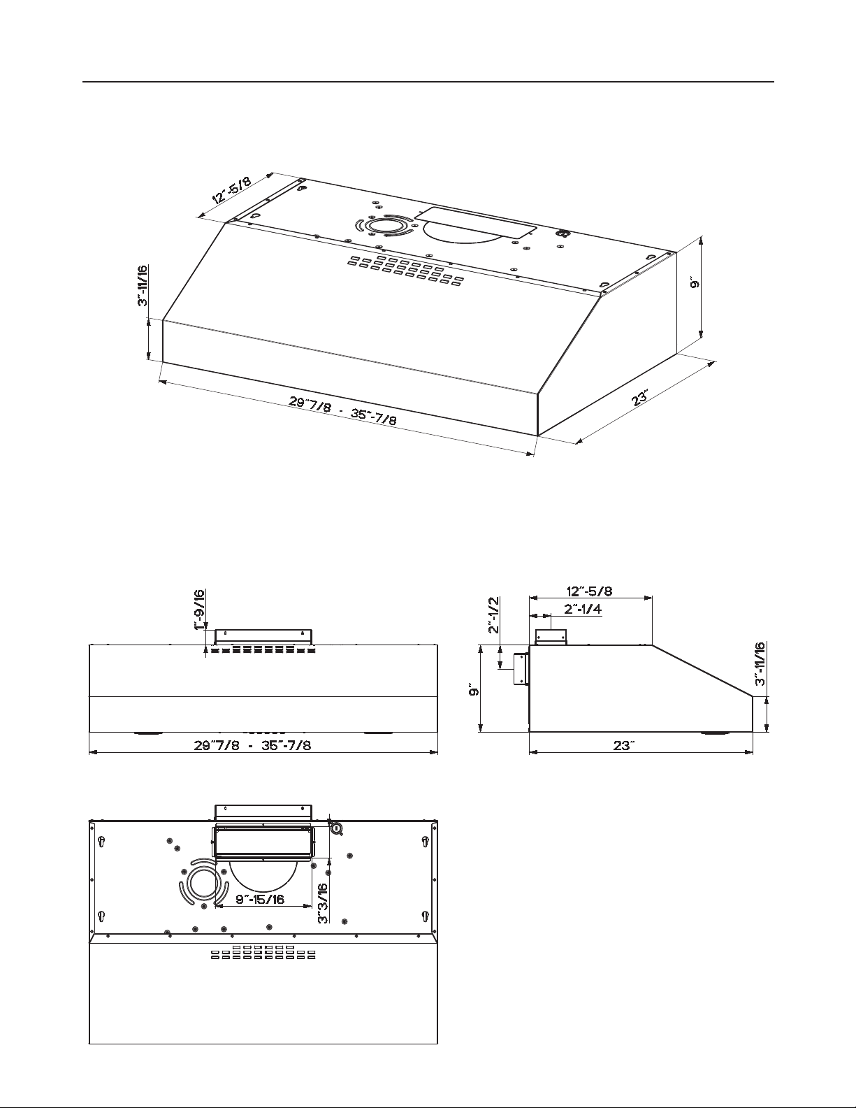
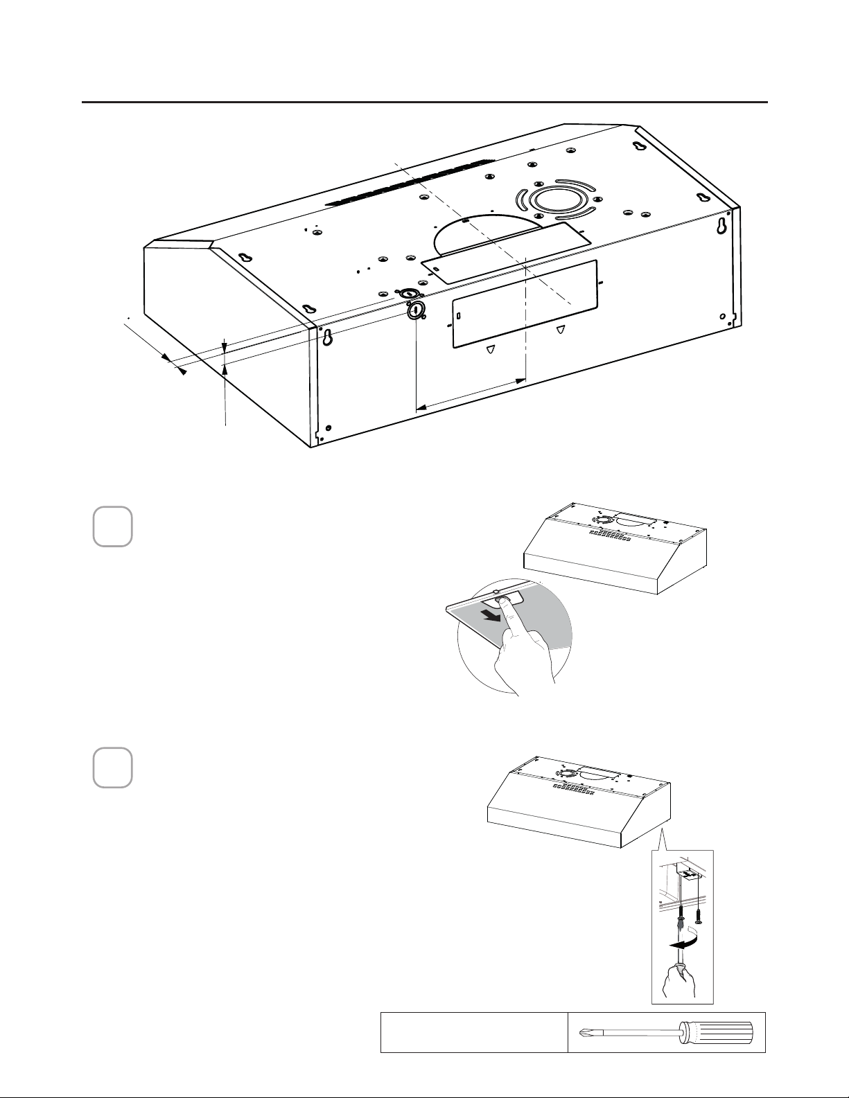
RANGE HOOD DIMENSIONS
RECTANGULAR OUTLET AIR
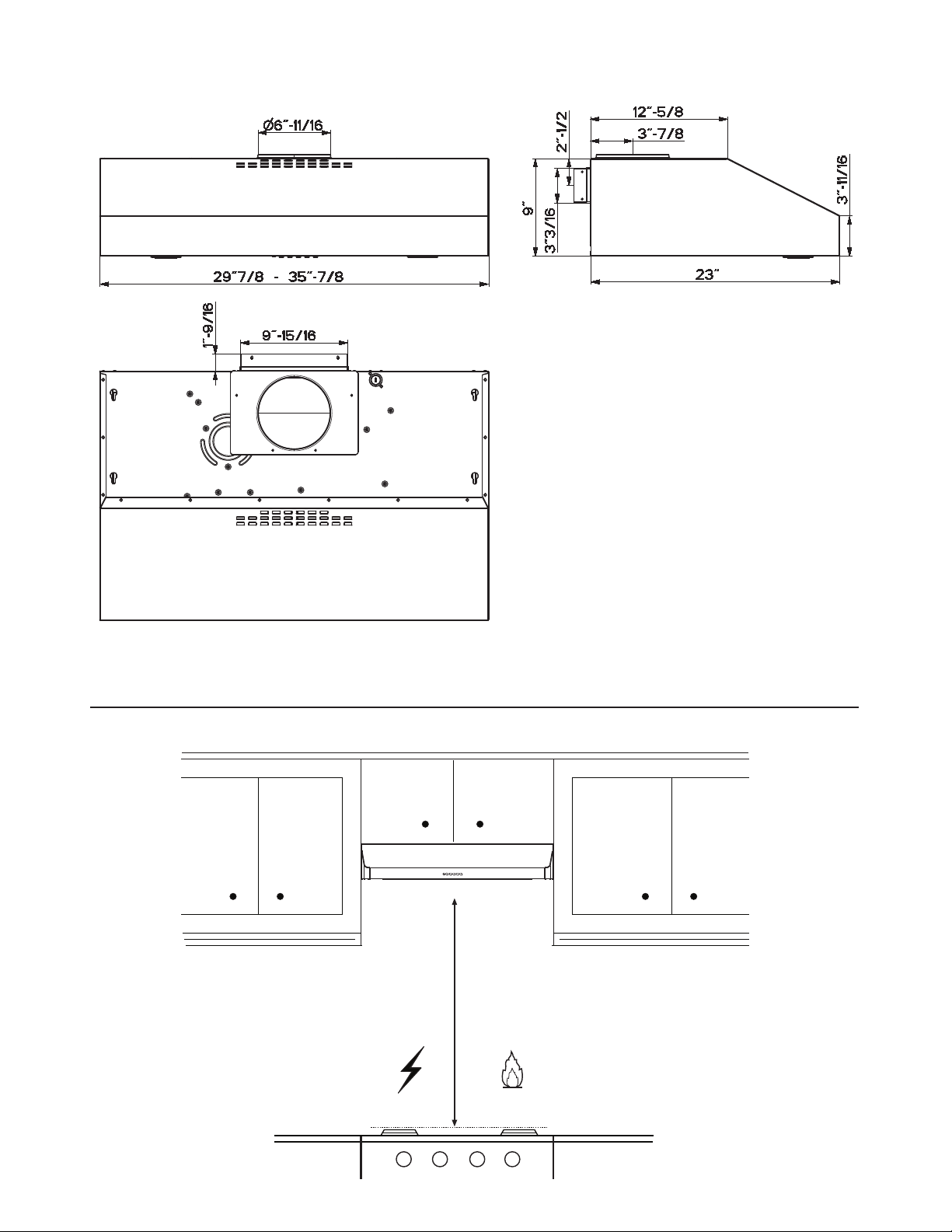
7
MIN. 24" OVER ELECTRIC / MIN. 30" OVER GAS
CIRCULAR OUTLET AIR
Min.24” Min.30”
INSTALLATION HEIGHT REQUIREMENTS
8
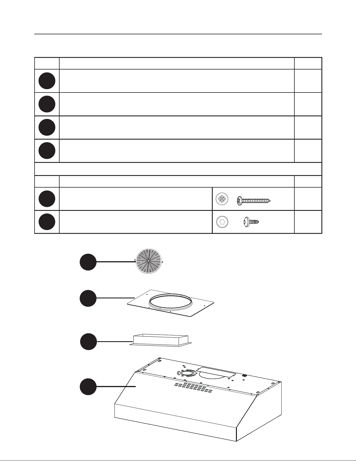
PARTS
REF. PART
A
Hood body – Includes Controls, Light, Filters, Blower 1
B
Damper ([)1
C
7" Round Flange
1
D
Grid (Only for Canadian Market)
1
REF
PART
E
3R]L6FUHZV[
4
F
7RU[6FUHZV[
4
PARTS INCLUDED
C
B
A
D
9
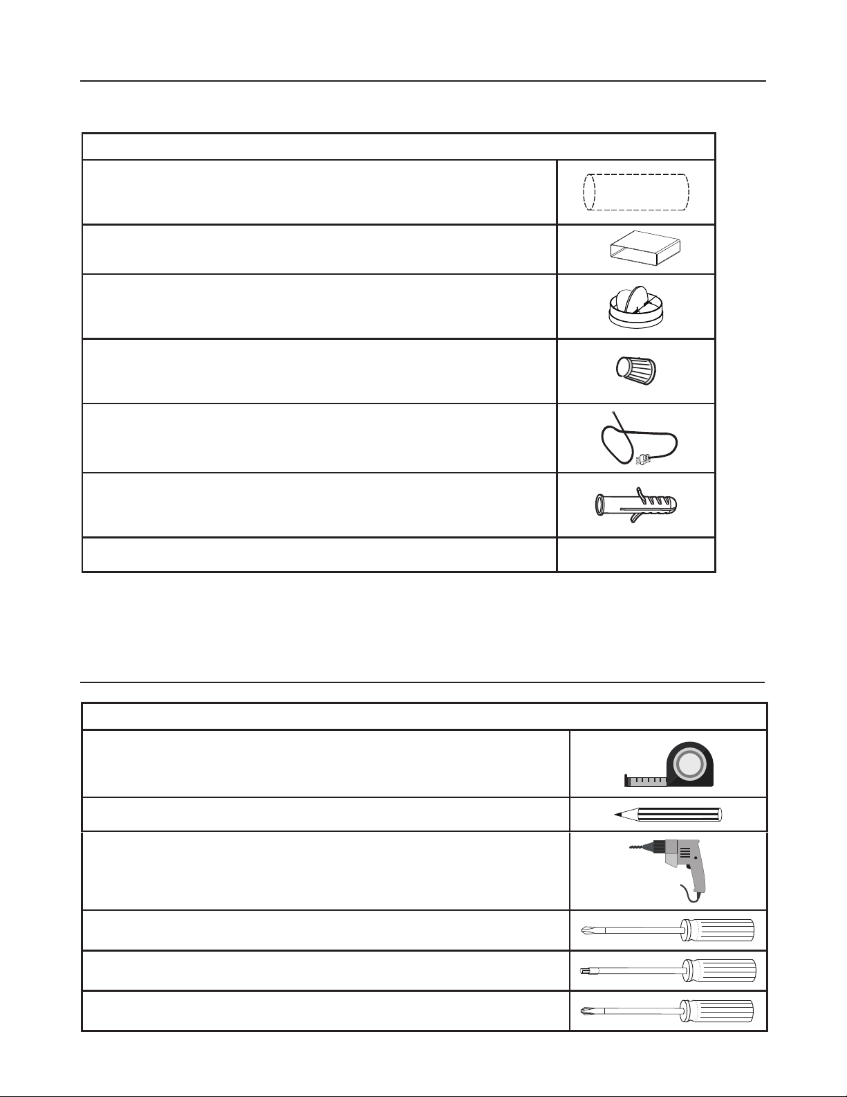
PARTS NEEDED
3$576FRQW
PART
7" Round Metal Ductwork
[5HFWDQJXODU'XFWZRUN
7" Damper
Wire connectors.
Power Supply Cable.
-
Drywall plugs or other suitable wall fasteners based on
your installation.
:DOO&DS5RRI&DS1HHGVWREHSXUFKDVHGVHSDUDWHO\
TOOLS NEEDED
TOOL
Tape Measure
Pencil
(OHFWULF'ULOOZLWK'ULOO%LW
Phillips Screwdriver
Torx Screwdriver
Pozi Screwdriver
10
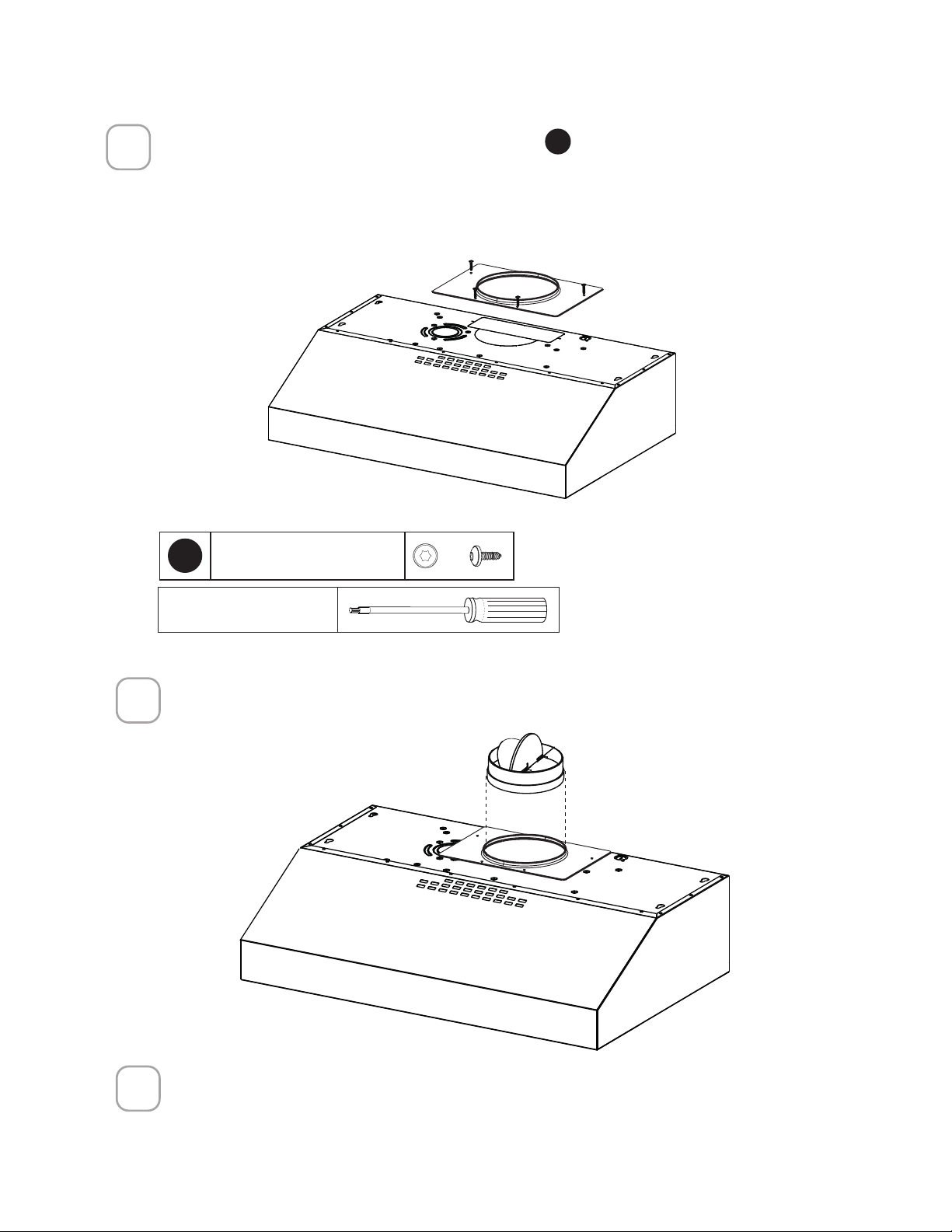
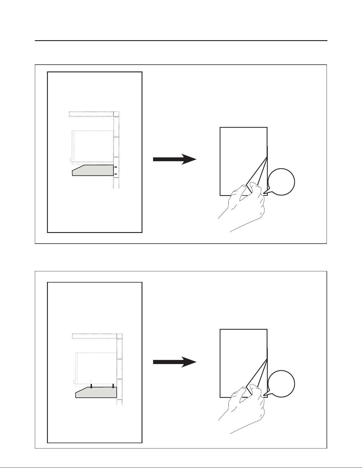
ONLY FOR CANADIAN MARKET
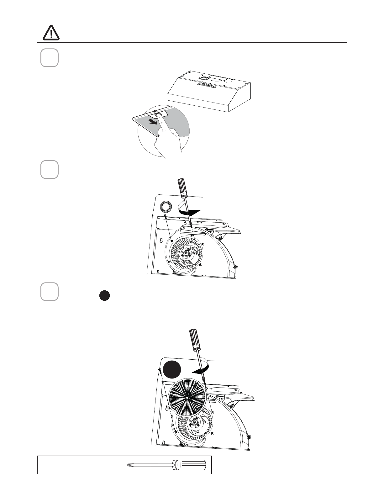
1
2
For ducted installations only:
5HPRYHWKH´OWHUVRQHDWDWLPHE\SXVKLQJWRZDUGVWKHEDFNRIWKHKRRGDQG
pulling down at the same time.
Install the screws as pictured.
Install Grid
D
with the two screws removed from step 2. Screw the protection
grid into the location shown in the picture below. (The correct location has a
rectangular cut out to accommodate the grid.)
7DNHFDUHWRVFUHZWKHJULGFRPSOHWHO\µXVKWRDYRLGXQZDQWHGQRLVH
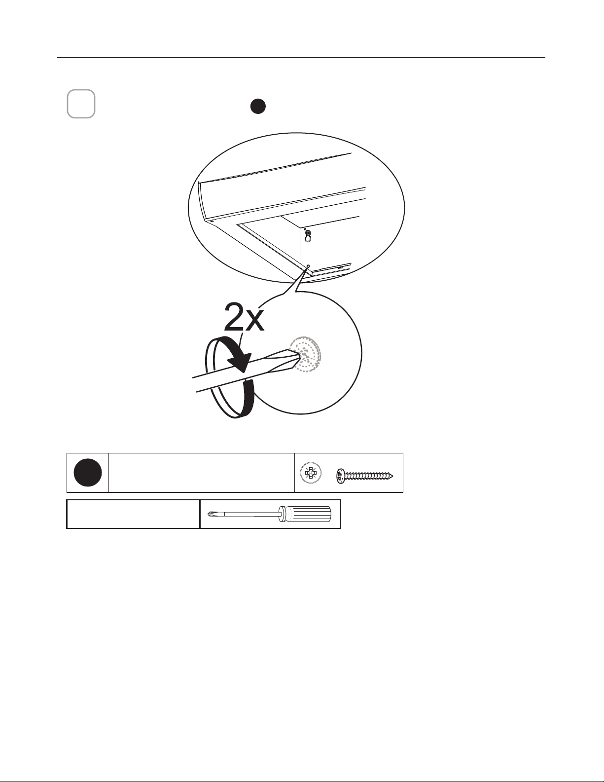
Remove the screws as pictured.
Remove two of the screws from the motor assembly housing as pictured.
3
Phillips Screwdriver
D
11
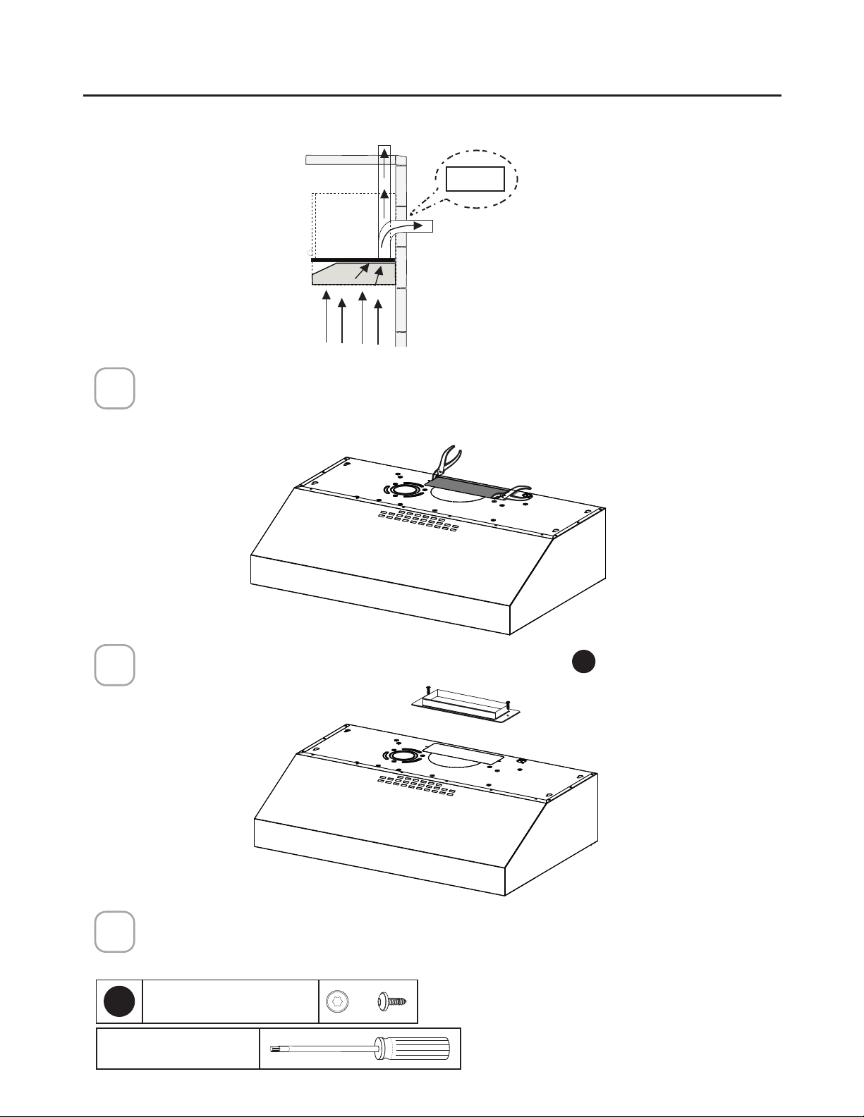
5HPRYHWKH´OWHUVRQHDW
a time by pushing them
towards the back of the
hood and pulling down at
the same time.
Remove the wiring box
cover by unscrewing
the 2 screws.
Preparing the hood for electrical knockouts
7" 1/2
13/16"
13/16"
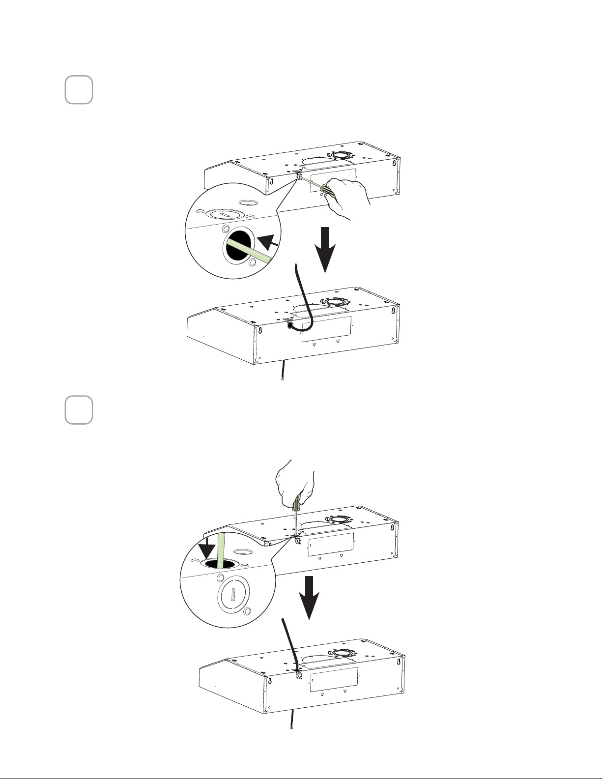
CHOOSE VERTICAL OR HORIZONTAL
ELECTRICAL CONNECTION KNOCKOUT'S
1
2
Phillips Screwdriver
12
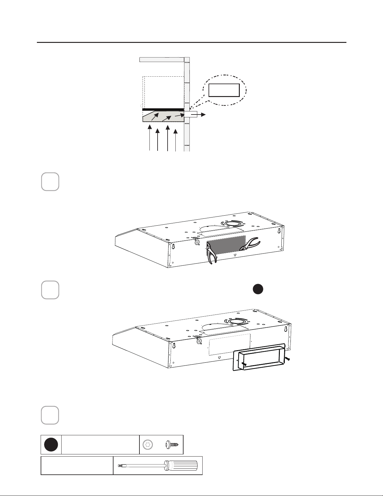
5HDU+ROH+RUL]RQWDO
Choose the rear hole for the electric connection and break with a screwdriver or other
tool.
During the installation thread Power Supply Cable through this hole.
3
7RS+ROH9HUWLFDO
Choose the top hole for the electric connection and break with a screwdriver or
other tool.
During the installation thread Power Supply Cable through this hole.
4
13
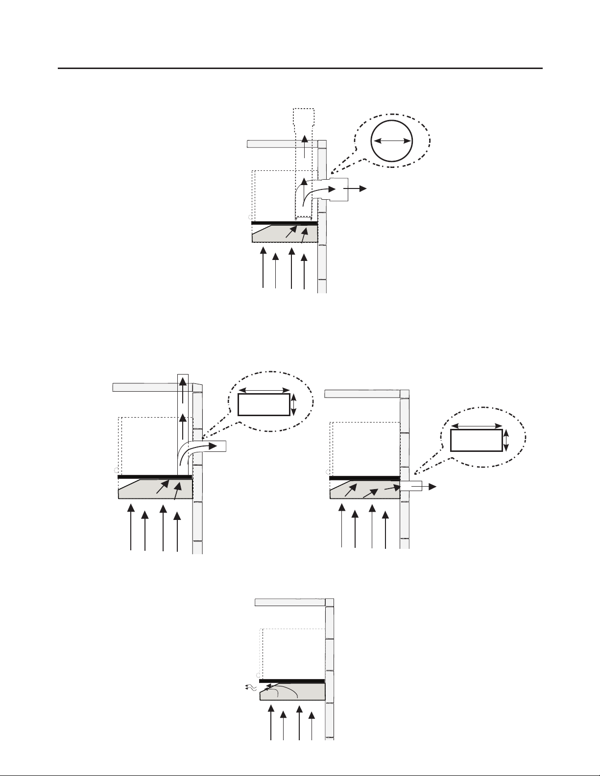
DUCTED VENTING METHOD OPTIONS
DUCTED WITH 7" ROUND OUTLET:
– Vertical
– Horizontal
DUCTED WITH 3 1/4" X 10" RECTANGULAR OUTLET
– Vertical
– Horizontal
7"
Rear
Top
10"
3 1/4"
10"
3 1/4"
Rear
Top
Go to page 14
Go to page 16
NON DUCTED - RECIRCULATION OPTION
Requires purchase of
Activated Charcoal
Accessory
Go to page 18
14
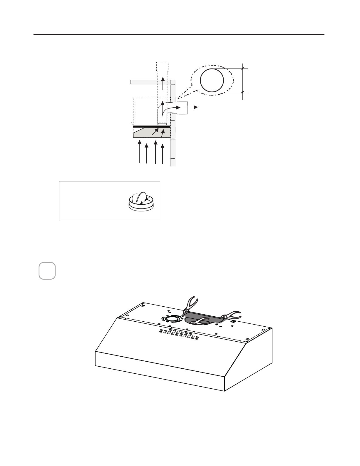
DUCTED - 7" ROUND OUTLET
Cut where indicated.
Remove both the rectangular and semicircle areas with metal shears.
Rear
Top
7"
Required; 7" Round
Damper purchase
separately.
1
Caution: If an elbow
is required, do it
as far away from
the hood's exhaust
opening as possible.
15
Install the Flange with Flange transition screws
F
.
Install 7" Round Damper purchased separately. Secure damper with foil duct tape.
Connect the 7" Round Metal Ductwork to the Roof or Wall Cap purchased separately
and then attach ductwork.
Go to page 19
2
3
Torx Screwdriver
NOTE: The Flange must be mounted with the lip facing upward.
2QO\XVHWKHVFUHZVSURYLGHGIRUWKHµDQJH
F
7RU[6FUHZV[
4
16
Choose the rectangular upper air outlet or rectangular rear air outlet and cut where
indicated.(See page 18 for Rear Outlet)
Install the included rectangular air outlet with two screws
F
.
Connect the metal ductwork to the Roof or Wall Cap purchased separately and
then attach ductwork.
Rear
Top
Top
3
1/4
" x 10"
DUCTED - 3 1/4" X 10" RECTANGULAR OUTLET
ON TOP
1
2
3
Torx Screwdriver
F
7RU[6FUHZV[
Caution: If an elbow is required,
do it as far away from the
hood's exhaust opening as
possible.
17
Go to page 19
Rear
Rear
3
1/4
" x 10"
Use the rear air outlet and cut where indicated.
Install the included rectangular air outlet with two screws
F
.
1
2
Torx Screwdriver
F
7RU[6FUHZV[
DUCTED - 3 1/4" X 10" RECTANGULAR OUTLET
REAR
Caution: If an elbow is required,
do it as far away from the
hood's exhaust opening as
possible.
Connect the metal ductwork to the Roof or Wall Cap purchased separately and
then attach ductwork.
3
18
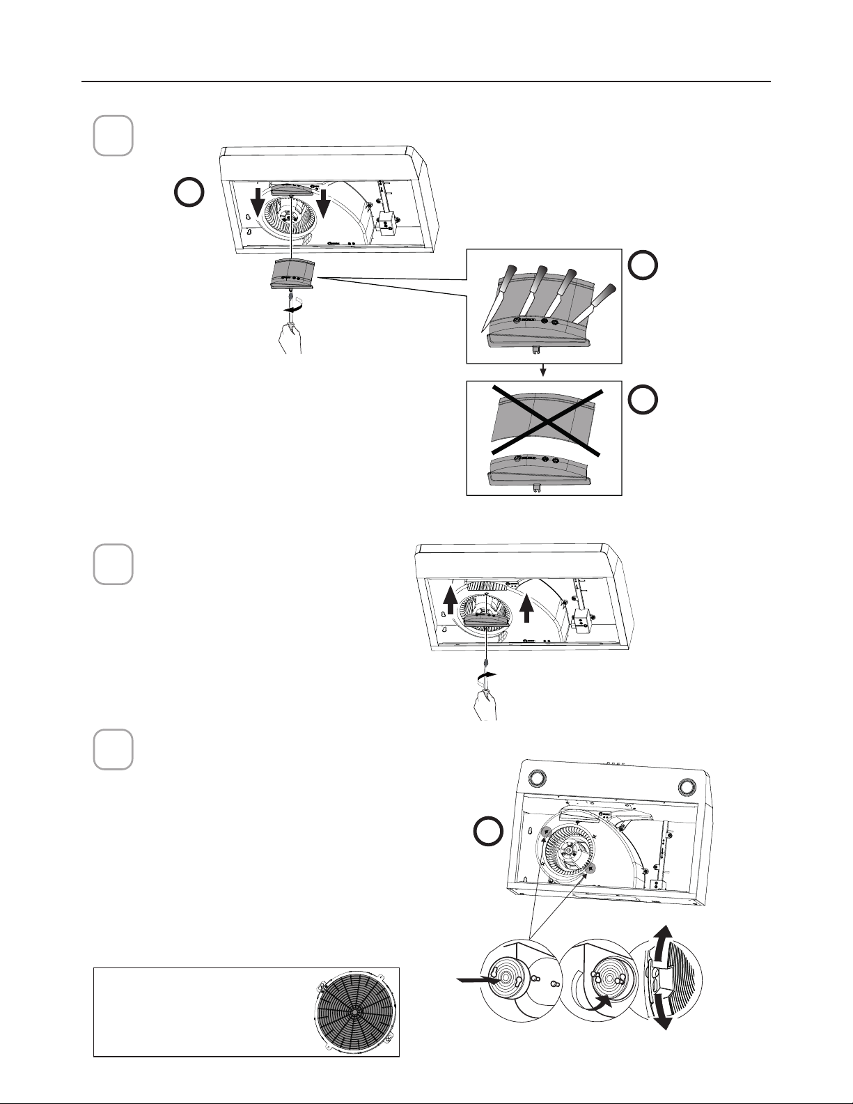
b1
a
b2
Remove the indicated blower cover (do not discard the screw).
Reinstall the modified blower cover
with the same screw.
Cut the
cover where
indicated in
picture b1.
Discard /
Recycle
upper pieces
of blower
cover.
Install the Activated Charcoal Filter purchased separately.where indicated in the picture "C".
c
NON DUCTED RECIRCULATION OPTION
1
2
3
Required Activated Charcoal
Filter Accessory - (FILTER5)
purchased separately.
Go to page 19
19
CHOOSING THE MOUNTING METHOD
Installation for Mounting on the Wall
Installation for Mounting to the cabinet
Page
20
Page
24
20
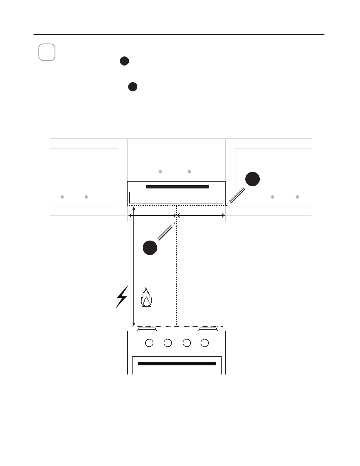
DRAW POSITIONING LINES
Draw a vertical line
H
from the supporting back wall to the ceiling or upper limit, at
the center of the area in which the hood will be installed.
Draw a horizontal line
I
from where the bottom edge of hood will be located, to
a minimum of 24" above an electric cooking surface and 30" above a gas cooking
surface.
1
MIN. 24" OVER ELECTRIC/MIN. 30" OVER GAS
I
H
MOUNTING RANGE HOOD ON WALL
==
Min. 24" Min.30"
21
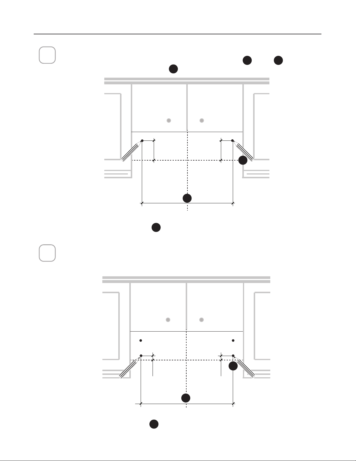
Mark the wall for the upper anchors.
0DUNWKHZDOOZKHUHLQGLFDWHGDERYHWKHKRUL]RQWDO
I
line at
J
distance on
the left and right of the vertical line
H
.
3
2 3/4”
2 3/4”
8 7/ 1 6 ”
8 7/ 1 6 ”
Mark the wall for lower anchors.
Mark 1” below the Step 2. Upper Anchors. Take care to keep level.
30" = 27
30" = 27
3/8
3/8
"
36" = 33
36" = 33
3/8
3/8
"
30" = 27
30" = 27
3/8
3/8
"
36" = 33
36" = 33
3/8
3/8
"
MOUNTING RANGE HOOD ON WALL
2
I
J
H
I
J
H
22
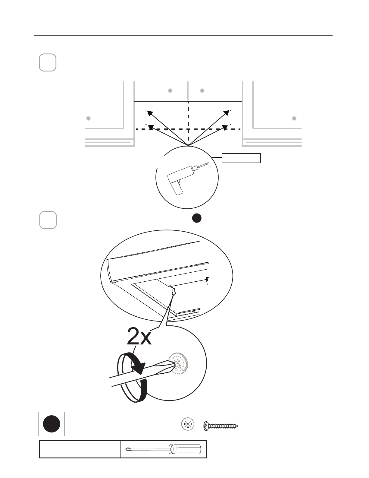
'ULOODWKKROHGLUHFWO\LQWRWKHZDOODWWKHFHQWHUSRLQWVPDUNHGLQVWHS
If fastener locations do not align with the studs, insert the purchased wall plugs in the holes.
In upper holes use two of the supplied screws
E
to secure the hood body to the wall.
´
;
5
Pozi Screwdriver
MOUNTING RANGE HOOD ON WALL
4
E
3R]L6FUHZV[
23
Using two remaining screws
E
anchor the hood in lower holes as indicated.
6
MOUNTING RANGE HOOD ON WALL
Pozi Screwdriver
E
3R]L6FUHZV[
24
MOUNTING RANGE HOOD UNDER THE CABINET
20"
24"-30"-36"
12"
7"
2" 13/16
10" 1/2
1" 5/16
1" 5/16
7" 11/16 2"
7" 1/2
13/16"
13/16"
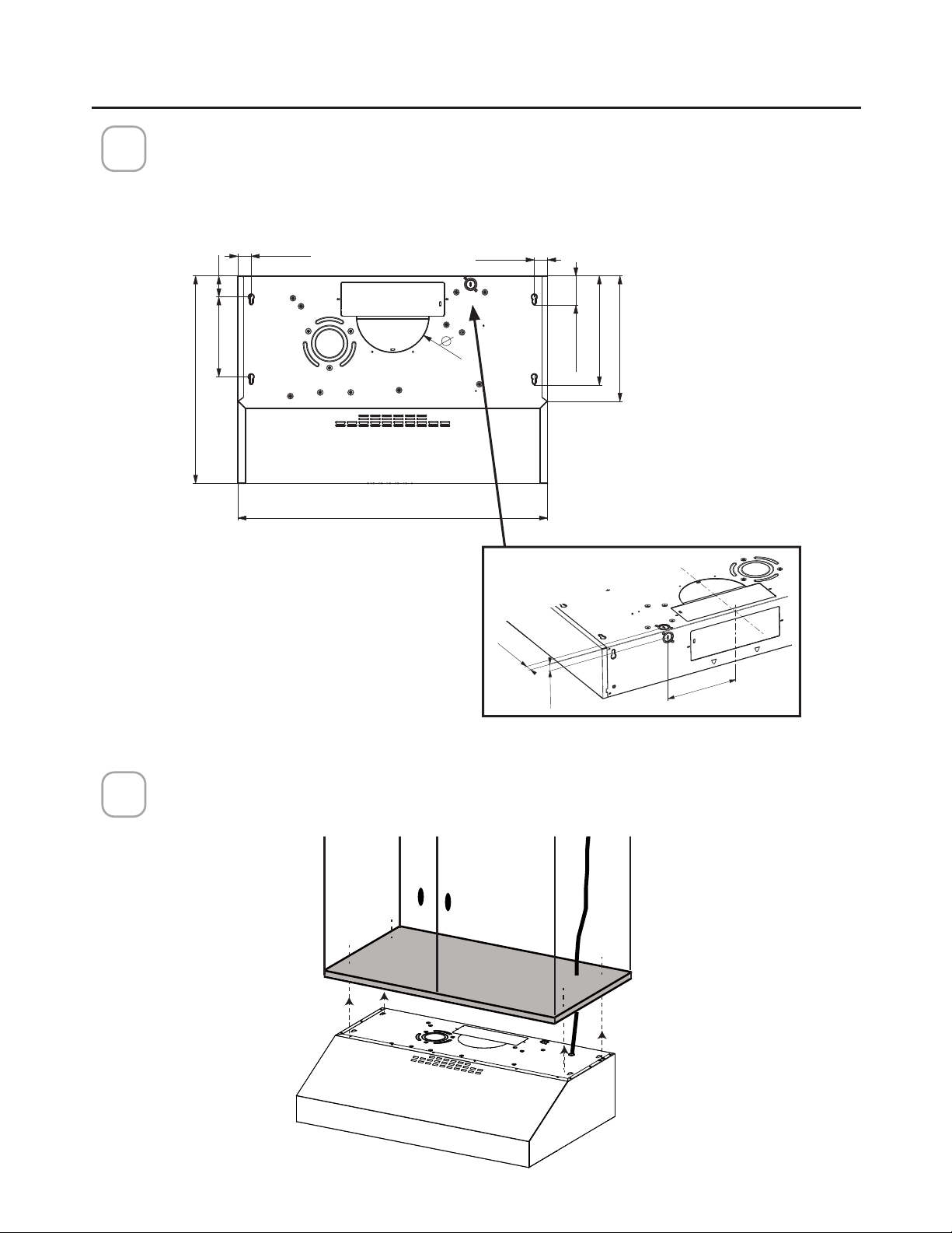
Locate the hole on the Range Hood for the power cord (See Section " CHOOSE
VERTICAL OR HORIZONTAL ELECTRICAL CONNECTION KNOCKOUT'S ") and pass
the cord through the appropriate hole.
Lift the hood to the cabinet and pass the power cord through the appropriate holes
on the Range Hood and through the cabinet to the power source.
1
2
Top View
BackView
23"
25
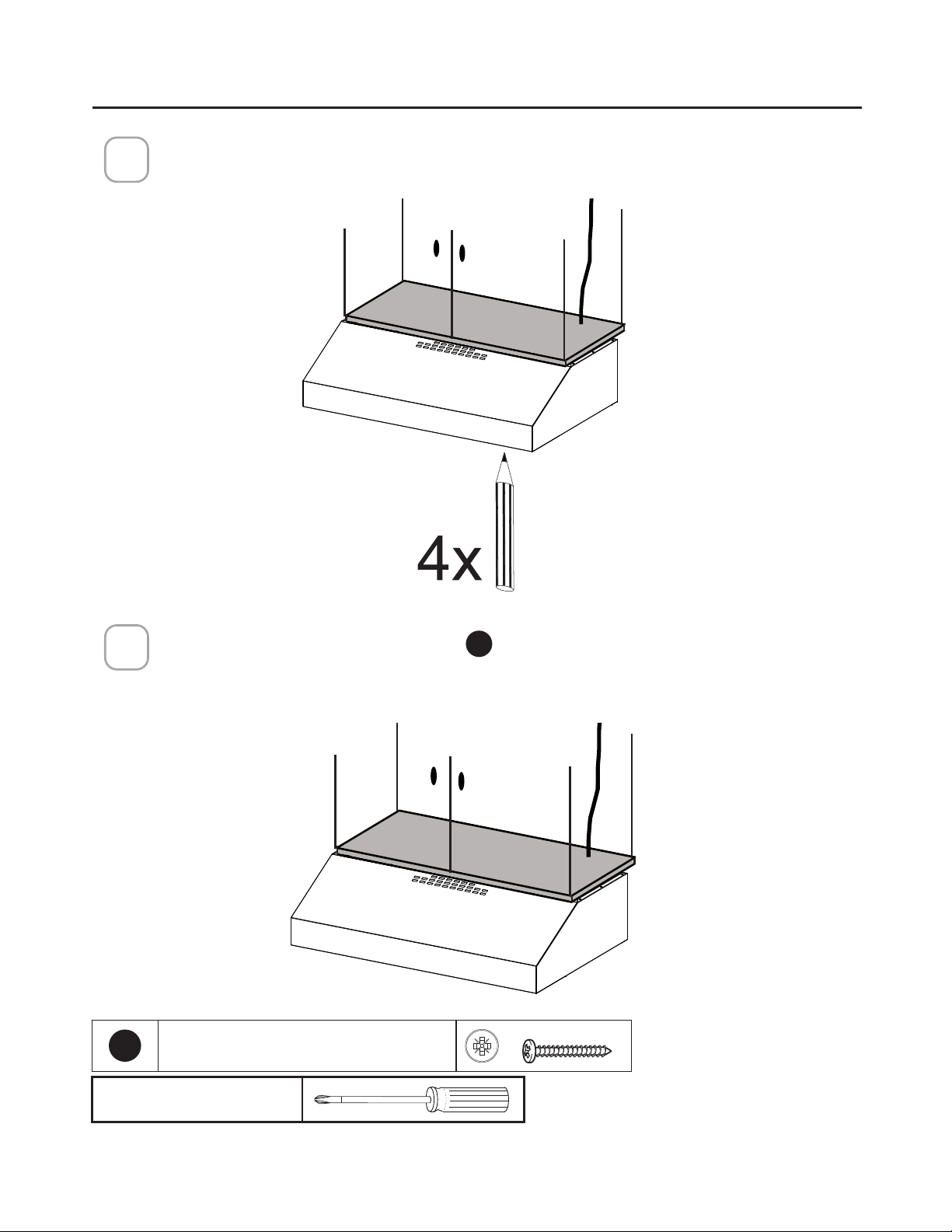
Mark the holes for attaching the hood to the cabinet. Verify the measurement with
the diagram on the previous page.
3
Attach the Hood body with 4 screws
E
from the bottom available with the hood.
4
E
3R]L6FUHZV[
Pozi Screwdriver
MOUNTING RANGE HOOD UNDER THE CABINET
26
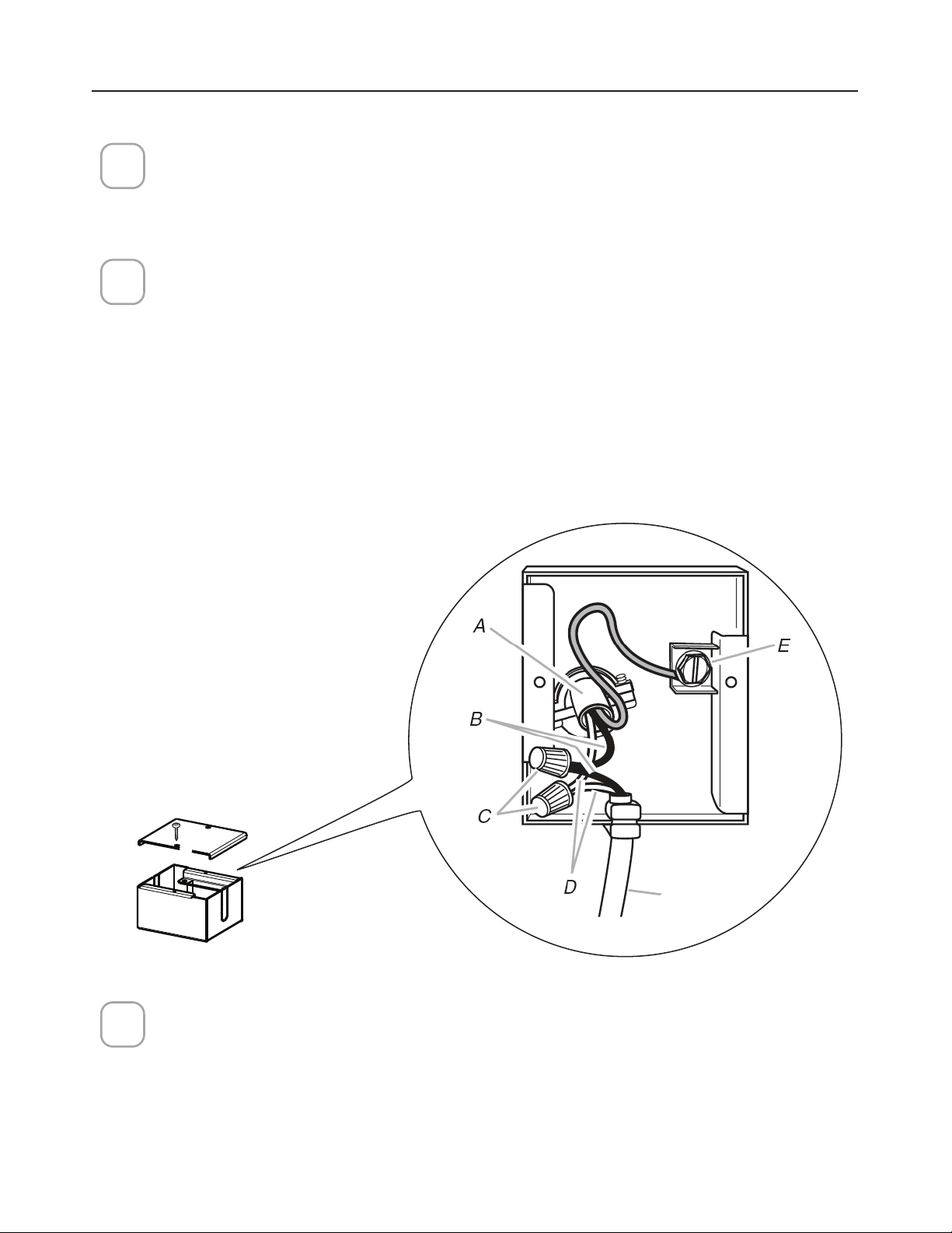
CONNECTING ELECTRICITY
Connecting the House Power.
Caution! Do not turn on the house power until the installation is complete.
• Feed the Power Supply Cable through the electrical knock out.
Wiring Box Connections.
• Attach the White lead of the Power Supply (A) to the White lead of the Range
Hood (D) with a twist-on type connector.
• Attach the Black lead of the Power Supply to the Black lead of the Range Hood
(B) with a twist-on type wire connector (C).
• Connect the Green (E) (Green and Yellow) ground wire under the grounding
screw.
1
3
2
Hood
wiring
5HSODFHWKH´HOGZLULQJFRPSDUWPHQWFRYHUDQGWKHJUHDVH´OWHUV
27
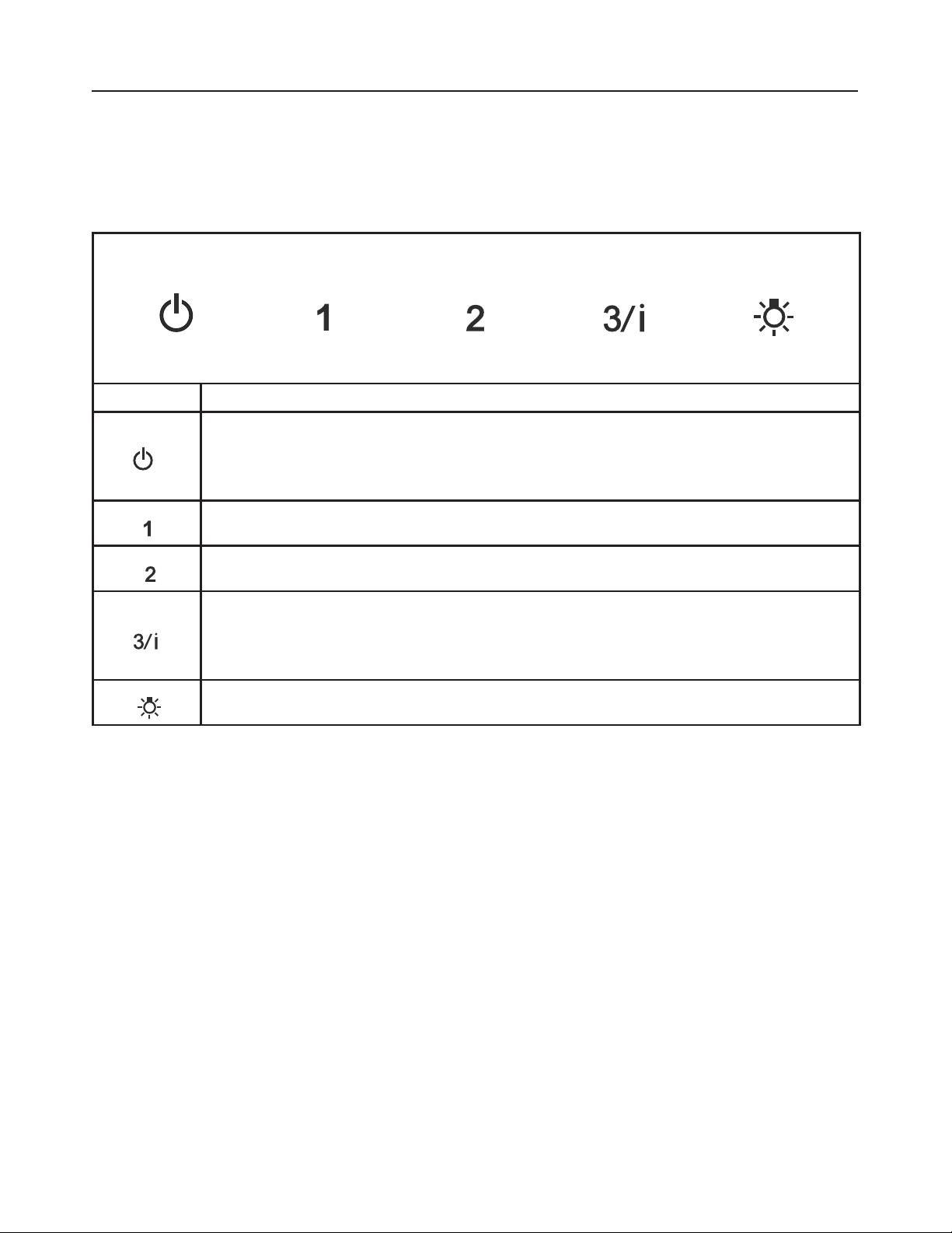
OPERATING THE CONTROLS
FOR BEST RESULTS
6WDUWWKH5DQJH+RRGVHYHUDOPLQXWHVEHIRUHFRRNLQJWRGHYHORSSURSHUDLUµRZ$OORZWKH
Range Hood to operate for several minutes after cooking is complete to clear all smoke and
odors from the kitchen.
Button Function
Fan Off Button:Turn the blower Off.
The fan can be operated by pressing any of the fan setting buttons.
Hold down this button for 2 seconds to activate delayed off function which will
keep the fan On for 15 minutes and automatically shut Off.
Fan Settings Buttons: Low Speed.
Fan Settings Buttons: Medium Speed.
Fan Settings Buttons: High Speed.
Hold down the button for 2 seconds to activate the INTENSIVE SPEED, which is timed
to run for 10 minutes. At the end of this time it will automatically return to the speed set
before.Suitable to deal with maximum levels of cooking fumes.
Light Button: On/Off switch for the Led lights.
28
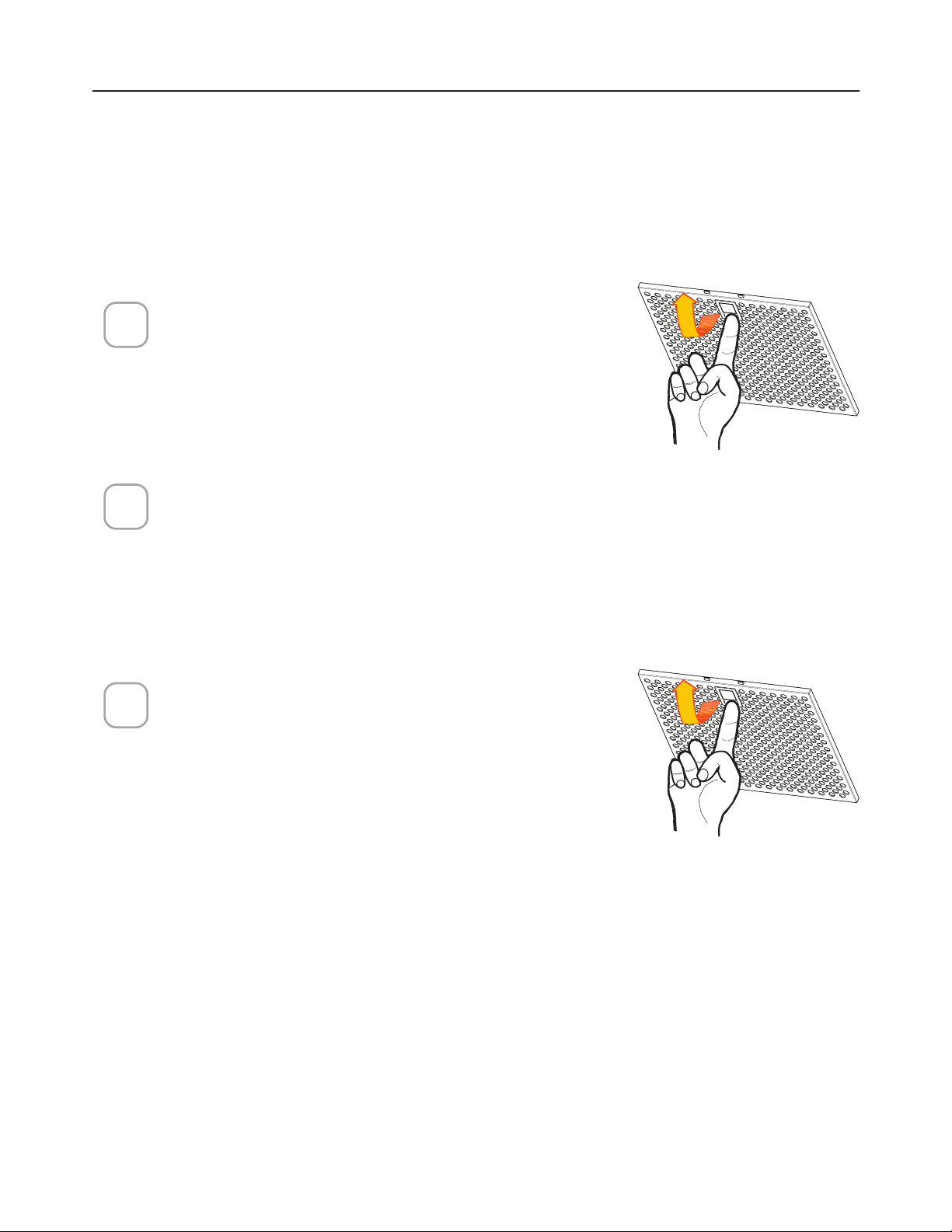
CARING FOR FILTERS
5HPRYHWKH´OWHUSXVKLQJWKHOHYHUWRZDUGV
the back of the unit while pulling downward.
:DVKWKH´OWHUZLWKRXWEHQGLQJLW/HDYHLWWR
dry thoroughly before replacing. If the surface
RIWKH´OWHUFKDQJHVFRORURYHUWLPHHI´FLHQF\
will not be affected.
7RUHSODFHWKH´OWHUSXVKWKH´OWHUXSLQWRSR-
sition while holding the lever back, then release
lever to lock in place.
1
2
3
CLEANING METAL GREASE FILTERS
7KHPHWDOJUHDVH´OWHUVFDQEHFOHDQHGLQKRWGHWHUJHQWVROXWLRQRUZDVKHG
in the dishwasher.
They should be cleaned every 2 months use, or more frequently if use is
particularly heavy.
NOTES:
&OHDQLQJLQDGLVKZDVKHUPD\GXOOWKH´QLVKRIWKHPHWDOJUHDVH´OWHUV
(QVXUHWKDWWKH´OWHUVDUHFRPSOHWHO\GU\EHIRUHLQVWDOOLQJWKHPEDFNLQWR
the Range Hood.
CLEANING EXTERIOR SURFACES
3OHDVHQRWHDEUDVLYHVDQGVFRXULQJDJHQWVFDQVFUDWFKUDQJHKRRG´QLVKHV
DQGVKRXOGQRWEHXVHGWRFOHDQ´QLVKHGVXUIDFHV
6WDLQOHVV6WHHO´QLVKFOHDQLQJLQVWUXFWLRQV
Clean exterior surfaces with a commercially available stainless steel cleaner.
29
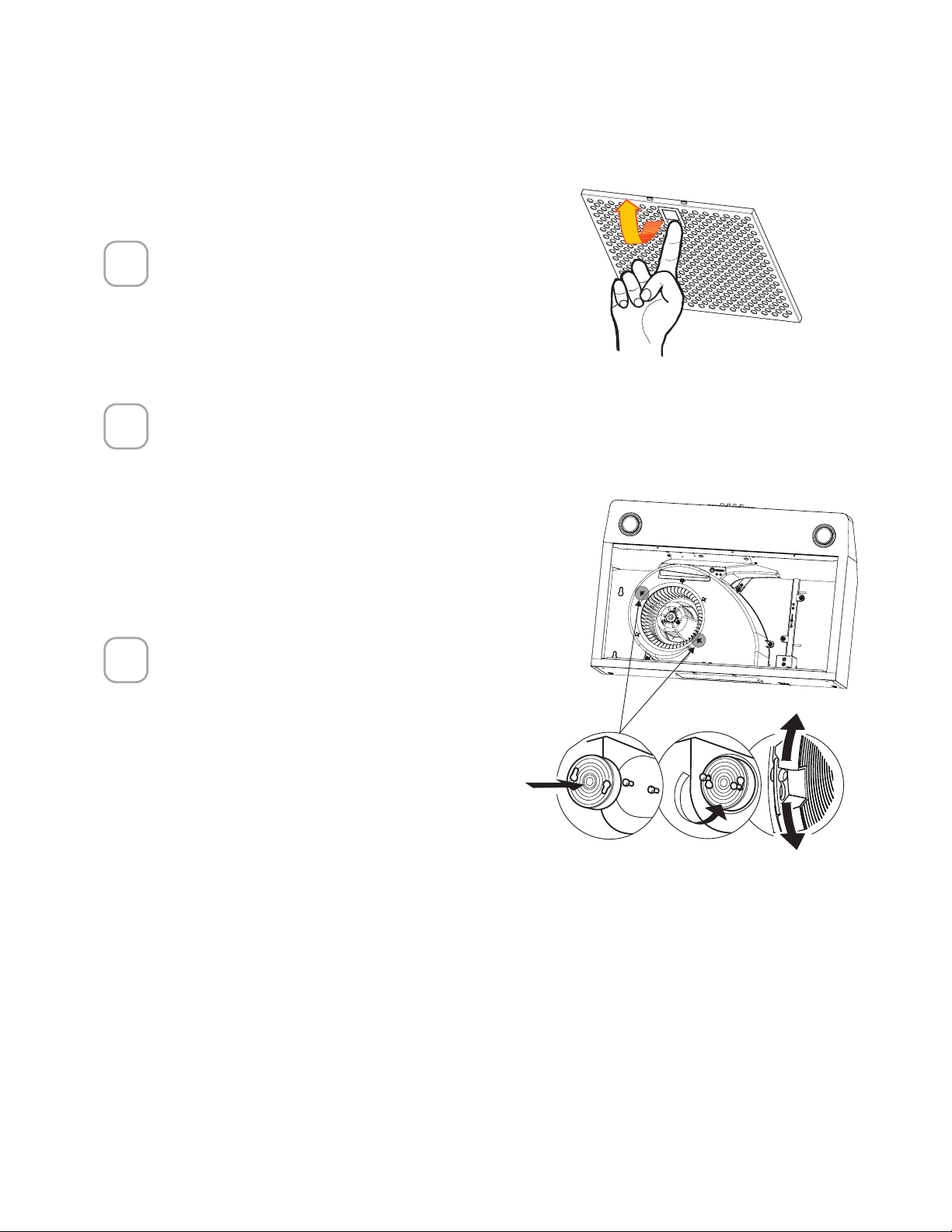
Remove the grease filters.
Remove the saturated carbon
filter by releasing the fixing
hooks or by removing the two
screws for Canadian applica-
tions.
Fit the new filter by hooking it
into its seating or by fixing it
with the two screws for Cana-
dian applications.
1
2
3
REPLACING ACTIVATED CHARCOAL FILTER
The Activated Charcoal Filters are not washable and cannot be regenerated,
and must be replaced approximately every 4 months of operation, or more
frequently with heavy usage.
30
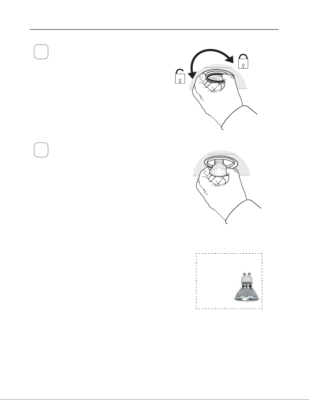
REPLACING LIGHTING
Gu10 self-ballasted led
lamps – listed in accor-
dance with ul
QP[M
DQFH
csa c22.2 No.
1993
1
5 W Led Type GU10 bulb
Remove the bulb (See the picture).
Replace the bulb with a new one of
the same type, making sure that you
insert the two pins properly into the
housings on the lamp holder and
twist to lock back in place.
Attention: The bulbs could be hot,
please wait some minutes before the
replacing.
2
31
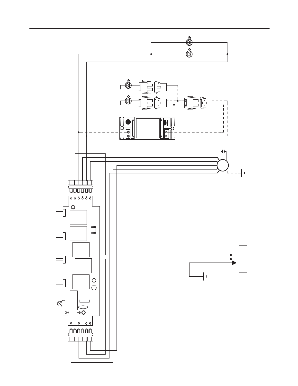
WIRING DIAGRAM
$U
$SFBU
$PEF
#-6
3&%
#-,
(3:
#-,
7
.$
'
7
&4;
.0503
:(
:(
41&&%
#-,#-,
'
7_)[
8)58)5
/
*
41&&%
-*()5
/
-
7
-
7
8)5
8)5
03(
7-5
03(
#-6
3&%
.7
#38
03(
:(
#-6
(3:
#-6
7-5
4&$
&-&$530/*$
53/4'03.&3
- /
#38
(3:SFE
#-,WMU
(3:(3:(3:
-&%
#-,#-,#-,
(3:(3:
-&%
#-,#-,
%3"'5
7-5
-&%
3&%
7-5
-&%
3&%

32
WARRANTY
Franke Home Solutions Warranty for Franke and Faber Branded Product
Effective March 1, 2022
In the United States, Canada and Latin America, Franke warrants the Faber branded products from manufacturing defects
in material and workmanship when purchased from a Franke or Faber Authorized Retailer pursuant to product-specific
warranties detailed herein (each, a “Warranty” and collectively, the “Warranties”). The products must be properly installed,
per Franke’s installation instructions, in their original installation, and used in normal indoor residential kitchen
applications. Any products or components which have been modified or altered from their original intended condition will
void the Warranty. The Franke Warranties for Faber branded products are limited to the original purchaser and are non-
transferrable. These Warranties do not include products purchased from non-Authorized Retailers, products that are
obsolete or discontinued, or products that were previous display models. All issues with installed products are considered
warranty claims and not subject to the Return Policy. Franke reserves the right to inspect any Franke / Faber product
reported to be defective pursuant to a Warranty claim and the original installation prior to providing a replacement product
and/or component. All decisions are final. In no situation shall the liability of Franke exceed the amount of the original
purchase price.
The Warranties do not cover, and Franke shall not be liable for, any damage to products or components resulting from
misuse or abuse, accidental damages, normal wear such as scuffs, scratches or finish reduction/fading, improper
installation, abnormal usage, negligence, damage caused by improper maintenance or cleaning. Damage caused by
impurities, corrosive chemicals or acts beyond Franke’s control are not covered by any Warranty. Service calls to correct
the installation of a range hood, instructions on how to operate a range hood, to replace or repair house fuses or to correct
house wiring or plumbing are not covered by any Warranty. Service calls to repair or replace range hood light bulbs, fuses
or filters and these consumable part costs are also excluded from Warranty coverage. Installation not in accordance with
electrical or plumbing codes or Franke / Faber documentation are not covered by any Warranty. Replacement parts or
repair labor costs for units operated outside the United States, Canada or Latin America, including any non-UL or C-UL or
non-NOM approved Franke / Faber range hoods are excluded from Warranty coverage. Expenses for travel and
transportation for service in remote locations and pickup and delivery charges are not covered by any Warranty. Franke /
Faber range hoods should always be serviced in the home in their original installation.
Franke / Faber product replacements do not include liability for project delays. Product replacements are not guaranteed
to be exact replacements. If the original product is not available at the time of the warranty claim, at Franke’s option, the
product replacements will be of similar size, material, and value. Any products or components which have been modified
or altered, from its original intended condition will void the warranty.
The Warranties do not allow recovery of incidental or consequential damages such as loss of use, delay, property
damage or other consequential damage, and Franke accepts no liability for such damages. Each Warranty is limited to
the conditions set forth herein and to the applicable warranty period specified herein and is exclusive. EXCEPT FOR THE
WARRANTIES SET FORTH HEREIN, FRANKE MAKES NO WARRANTY WHATSOEVER WITH RESPECT TO THE
PRODUCTS, INCLUDING, BUT NOT LIMITED TO, (1) ANY WARRANTY OF MERCHANTABILITY, (2) WARRANTY OF
FITNESS FOR A PARTICULAR PURPOSE, (3) WARRANTY OF TITLE, OR (4) WARRANTY AGAINST INFRINGEMENT
OF INTELLECTUAL PROPERTY RIGHTS OF A THIRD PARTY, WHETHER EXPRESS OR IMPLIED BY LAW, COURSE
OF DEALING, COURSE OF PERFORMANCE, USAGE OF TRADE OR OTHERWISE. LEGAL DISCLAIMER PLEASE
READ CAREFULLY. Franke Kitchen Systems LLC provides the above information to you as a public service to our
customers. By accessing and using this information, you agree to the following and to comply with all applicable laws. If
you do not agree with these terms and conditions, do not use this information. While we try to keep the information
current, changes may have occurred since its creation. Contact your Regional Manager or Customer Service to verify
information regarding Franke Kitchen Systems LLC programs and their use by you.
Franke / Faber Range Hood Limited Warranty:
Franke / Faber range hoods are warranted against any defect in materials or workmanship for the original purchaser for a
period of two (2) years from the date of original purchase when used in standard residential indoor applications. This
warranty covers labor and replacement parts. Franke, at its option, may repair or replace the product or components
necessary to restore the product to good working condition.

33
This warranty supersedes all other warranties, expressed or implied. No employee, field sales representatives, or
distribution persons are authorized to give any warranties on behalf of Franke Kitchen Systems, LLC
To make an installed product warranty claim please contact Franke at the provided contact information below. All warranty
claims must include the following for processing:
1. Proof of purchase from Franke or Faber Authorized Retailer
2. Original purchaser’s name, address (included city, state, zip), email address and phone number
3. Franke / Faber model and serial number
4. Date of installation
5. Description of the defect
6. Photos of the defect
In North America and Latin America:
Franke Home Solutions
Attn: Warranty Department
800 Aviation Parkway
Smyrna, TN 37167
Legal Entity:
Franke Kitchen Systems LLC

991.0xxx.xxx_01 - 220201
D0000xxxx_00