Outdoor Lifestyles by Hearth & Home Technologies • Montana US-CAN • 4039-156 Rev R • 09/19/13
1
Owner’s Manual
Installation and Operation
Models:
Montana-36
Montana-42
Woodburning Fireplace
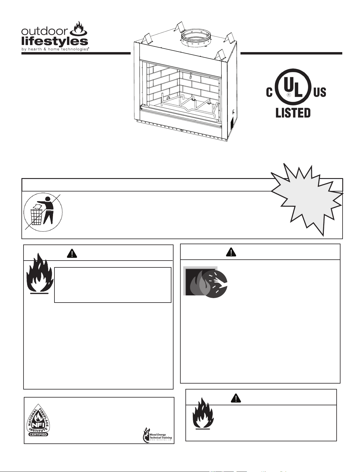
DO NOT DISCARD THIS MANUAL
CAUTION
• Important operating
and maintenance
instructions included.
• Leave this manual with
party responsible for
use and operation.
• Read, understand
and follow these
instructions for safe
installation and
operation.
DO NOT
DISCARD
Installation and service of this replace should
be performed by quali ed personnel. Hearth
& Home Technologies suggests NFI certi ed
or factory-trained professionals, or technicians
supervised by an NFI certified
professional.
Fire Risk
• For use with solid wood fuel or decorative
gas appliance only.
• Do not install unvented gas logs.
WARNING
If the information in these instruc-
tions is not followed exactly, a
re may result causing property
damage, personal injury, or death.
• Do not store or use gasoline or other am-
mable vapors and liquids in the vicinity of
this or any other appliance.
• Do not over re. Over ring will void your
warranty.
• Comply with all minimum clearances to
combustibles as speci ed. Failure to
comply may cause house re.
WARNING
HOT SURFACES!
Glass and other surfaces are hot during
operation and cool down.
WARNING
• CAREFULLY SUPERVISE children in same room as
appliance.
• Alert children and adults to hazards of high
temperatures.
High temperatures may ignite clothing or other
ammable materials.
• Keep clothing, furniture, draperies and other combustibles
away.
Hot glass will cause burns.
• Do not touch glass until it is cooled
• NEVER allow children to touch glass
• Keep children away
Outdoor Lifestyles by Hearth & Home Technologies • Montana US-CAN • 4039-156 Rev R • 09/19/13
2
Read this manual before installing or operating this replace.
Please retain this owner’s manual for future reference.
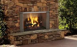
Congratulations on selecting a Outdoor Lifestyles wood
burning replace. The Outdoor Lifestyles replace you have
selected is designed to provide the utmost in safety, reliability
and efciency.
As the owner of a new replace, you’ll want to read and
carefully follow all of the instructions contained in this owner’s
manual. Pay special attention to all cautions and warnings.
This owner’s manual should be retained for future reference.
We suggest you keep it with your other important documents
and product manuals.
The information contained in this owner’s manual unless noted
otherwise, applies to all models and gas control systems.
Your new Outdoor Lifestyles wood burning replace will give
you years of durable use and trouble-free enjoyment. Welcome
to the Outdoor Lifestyles family of replace products!
Homeowner Reference Information
Model Name: Date purchased/installed:
Serial Number: Location on replace:
Dealership purchased from: Dealer phone:
Notes:
We recommend that you record the following pertinent
information about your replace:
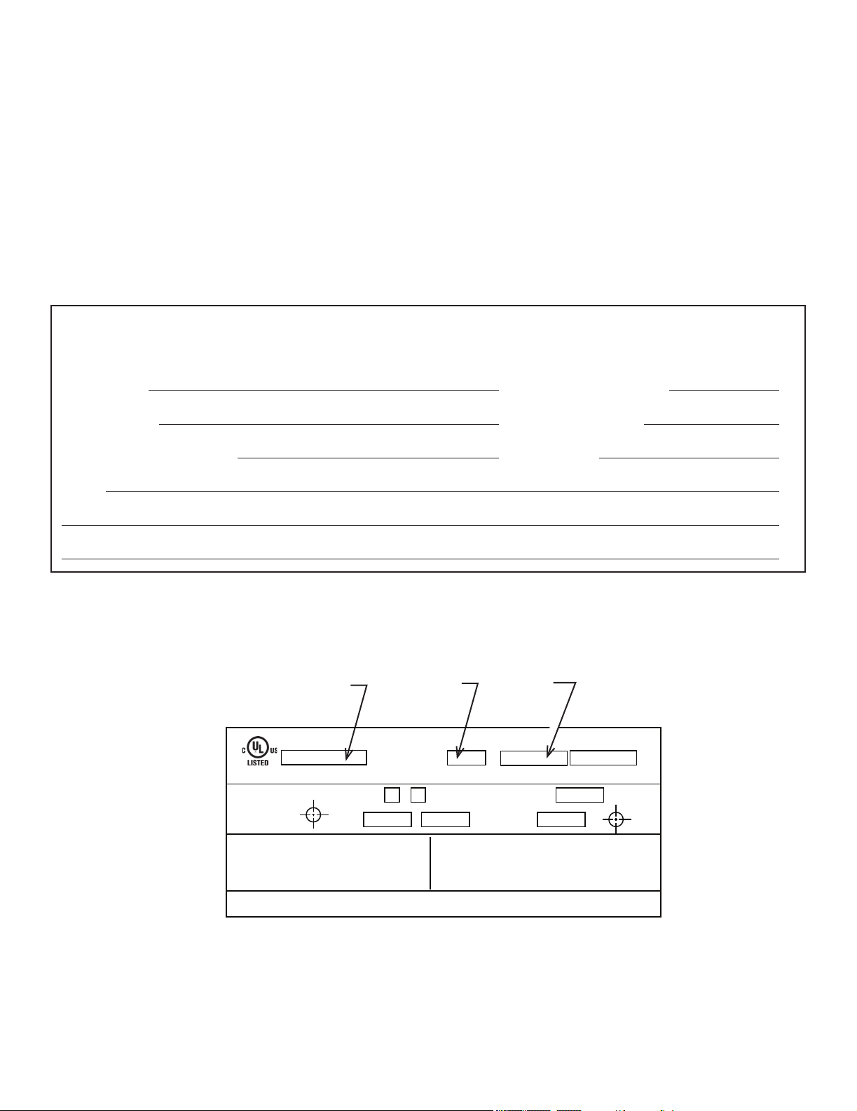
Listing Label Information/Location
The model information regarding your specic replace can be found on the rating plate located on the smoke shield of the
replace.
Congratulations!
Grate
Serial Number
FIREPLACE NO.
MODEL NO.
MODEL NO.
MFG. DATE
WARNING: RISK OF
FIRE DAMAGE. REPLACE
GRATE WITH HEARTH & HOME
TECHNOLOGIES INC.
OUTDOOR FIREPLACE INTENDED FOR USE WITH HEARTH & HOME TECHNOLOGIES INC. LISTED FIREPLACE PARTS. SEE INSTALLATION AND
OPERATING INSTRUCTIONS FOR THIS MODEL. ONLY HEARTH & HOME TECHNOLOGIES INC. GLASS DOOR KITS CAN BE INSTALLED ON THIS UNIT.
FIREPLACE ALSO FOR USE
IN MANUFACTURED HOMES
YES
NO
CLEARANCE TO
COMBUSTIBLES:
CHIMNEY
2 IN. MIN.
FIREBOX
IN.
MIN.
FAN KIT
MODEL NO.
&
RATED AT
115 VOLTS, 50/60 Hz.,
AMP.
DO NOT OVERFIRE. USE ONLY: SOLID WOOD FUEL OR
LISTED DECORATIVE GAS APPLIANCE. DO NOT USE A
FIREPLACE INSERT OR OTHER PRODUCTS NOT
SPECIFIED FOR USE WITH THIS PRODUCT. IF DOORS
ARE USED OPERATE FIREPLACE WITH DOORS FULLY
OPEN OR CLOSED ONLY. WHEN BURNING A
DECORATIVE GAS APPLIANCE IN THE FIREPLACE,
ADJUST DAMPER TO THE FULLY OPEN POSITION.
WARNING! THIS FIREPLACE HAS NOT BEEN TESTED WITH AN UNVENTED
GAS LOG SET. TO REDUCE THE RISK OF FIRE OR INJURY, DO NOT
INSTALL AN UNVENTED GAS LOG SET INTO FIREPLACE.
WARNING! TO AVOID THE RISK OF DAMAGING FIREPLACE MATERIALS
AND INCREASING THE RISK OF SPREADING A FIRE DO NOT USE THE
FIREPLACE TO COOK OR WARM FOOD.
IF INSTALLATION OR OPERATING INSTRUCTIONS ARE MISSING
CONTACT: HEARTH & HOME TECHNOLOGIES INC.,
1915 W. SAUNDERS ST., MT. PLEASANT, IA 52641.
Fireplace
Model

Outdoor Lifestyles by Hearth & Home Technologies • Montana US-CAN • 4039-156 Rev R • 09/19/13
3
Table of Contents
1 Listing and Code Approvals
A. Appliance Certication .........................4
2 Getting Started
A. Design and Installation Considerations ............5
B. Typical Fireplace System. . . . . . . . . . . . . . . . . . . . . . . 5
C. Tools and Supplies Needed .....................6
D. Inspect Fireplace and Components ...............6
3 Framing and Clearances
A. Selecting Fireplace Location ....................7
B. Clearances .................................9
C. Sidewalls/Surrounds .........................10
D. Frame the Fireplace .........................10
E. Chimney Requirements .......................11
4 Installation of Fireplace
A. Install the Dual Cooling Air Kit ..................12
B. Secure the Fireplace .........................13
5 Chimney Assembly
A. Chimney Requirements .......................14
B. Using Offsets/Returns ........................15
C. Assemble the Chimney Sections ................16
D. Install the Ceiling Firestops ....................16
E. Install the Attic Insulation Shield ................17
F. Double-check the Chimney Assembly ............17
G. Secure the Chimney .........................17
6 Complete the Enclosure
A. Chimney Termination .........................18
B. Chase Top .................................19
C. Install the Termination Cap ....................20
7 Accessories
A. Gas Log/Lighter Provisions ....................22
8 Finishing
A. Hearth Extension ............................23
B. Finishing Material ...........................24
C. Mantel ....................................24
D. Sidewalls/Surrounds .........................24
E. Glass Doors ................................24
9 Operating Instructions
A. General Information ..........................25
B. Clear Space Near the Fireplace ................26
C. Flue Damper ...............................26
D. Firescreen .................................26
E. Glass Doors ................................26
F. Grate .....................................26
G. Wood Fuel .................................27
H. Starting a Fire ..............................28
10 Troubleshooting
Diagnostics and Problem Solving. . . . . . . . . . . . . . . . . . . 29
11 Maintenance and Servicing the Fireplace
A. Disposal of Ashes ...........................30
B. Chimney Inspection/Cleaning ..................30
C. Firebox Refractory Replacement ................30
D. Maintenance Task List ........................31
E. Chimney Fire ...............................31
12 Reference Materials
A. Fireplace Dimensions ........................32
B. Fireplace Components .......................33
C. Chimney Components ........................34
D. Service Parts ...............................38
E. Limited Warranty ............................42
F. Contact Information ..........................44
Note: An arrow () found in the text signies change in content.
►
►
►
►
Outdoor Lifestyles by Hearth & Home Technologies • Montana US-CAN • 4039-156 Rev R • 09/19/13
4
1
Listing and Code Approvals
A. Appliance Certication
This replace system has been tested and listed in accor-
dance with UL 127 and CAN/ULC-S610-M87 standards by
Underwriters Laboratories Inc. for installation and operation
in the United States and Canada..
This replace has been tested and listed for use with the op-
tional components specied in this manual. These optional
components may be purchased separately and installed at
a later date.
Installation of a dual cooling air kit is required and must be
installed at the time of the initial replace installation. Failure
to do so may result in a re causing property damage and/
or personal injury.
Outdoor Lifestyles is a registered trademark of Hearth &
Home Technologies.
Not intended for use as a primary heat source.
This replace is tested and approved as a decorative
replace. It should not be factored as a primary heat
source in residential heating calculations.
Improper installation, adjustment, alteration, service
or maintenance can cause injury or property damage.
Refer to the owner’s information manual provided with
this replace. For assistance or additional information
consult a qualied installer, service agency or your
dealer.
WARNING
Fire Risk
• Do not install or operate damaged replace.
• Do not modify replace.
• Installation other than as instructed by Hearth & Home
Technologies is strictly prohibited.
• Do not operate the replace without fully assembling
all components.
• Do not overre.
• Do not install an unvented gas log set. This replace
has not been tested for use with unvented gas log
sets.
• Installation and/or use of any component part not
approved by Hearth & Home Technologies.
Hearth & Home Technologies disclaims any responsibility
for, and the warranty and agency listing will be voided by
the above actions.
WARNING
Fire Risk
WARNING
TO AVOID THE RISK OF DAMAGING FIREPLACE MA-
TERIALS AND INCREASING THE RISK OF SPREAD-
ING A FIRE, DO NOT USE THE FIREPLACE TO
COOK OR WARM FOOD.
Outdoor Lifestyles by Hearth & Home Technologies • Montana US-CAN • 4039-156 Rev R • 09/19/13
5
2
Getting Started
A. Design and Installation Considerations
Draft is the pressure difference needed to vent replaces
successfully. Considerations for successful draft include:
• Location of replace and chimney
Check building codes prior to installation.
• Installation MUST comply with local, regional,
state and national codes and regulations.
• Consult insurance carrier, local building inspector,
re ofcials or authorities having jurisdiction about
restrictions, installation inspection, and permits.
CAUTION
When planning a replace installation, it is necessary to de-
termine the following information before installing:
• Where the fireplace is to be installed. See Sections
3 and 4.
• The vent system conguration to be used. See Sections
5 and 6.
• Framing and nishing details. See Sections 3, 6 and 8.
• Whether optional accessories are desired. See
Section 12.
Moisture Resistance:
This outdoor replace will shed moderate amounts of water,
but is not waterproof. Water and condensing water vapor
may enter the chase under certain conditions.
The replace will not perform as an exterior wall. Moisture
penetration must be considered for construction that places
the replace in structure walls or on moisture sensitive sur-
faces.
When installed on exterior walls: Hearth & Home Tech-
nologies recommends that the replace chase be con-
structed outside the structure’s weather envelope. Where
the platform meets the wall, use a ashing detail similar to
that required for attached decks. Chase platforms, including
hearths should slope away from the structure at 1/8 in. to
1/4 in. per foot. The replace can be shimmed level.
When installed on surfaces where water may collect or
cause damage: Hearth & Home Technologies recommends
that a drainage pan be placed under the unit. This can be
constructed of metal, adhesive polymer membrane (such as
ice and water shield) or other suitable materials. A means of
drainage out of the pan such as tubes or weep holes should
be provided. A slope of 1/8 in. to 1/4 in. per foot towards
the drain port is suggested. The replace can be shimmed
level.
Hearths should slope away from the front of the replace
and chase at 1/8 in. to 1/4 in. per foot. Spark strips must be
on top of any combustible hearth materials used for moisture
management.
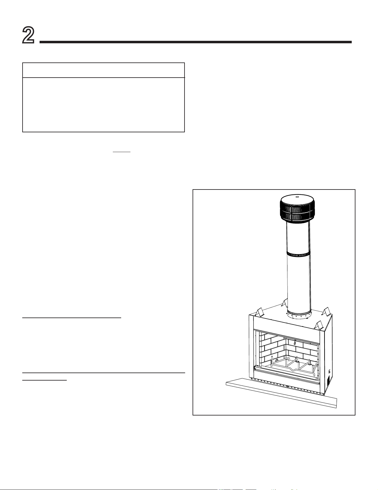
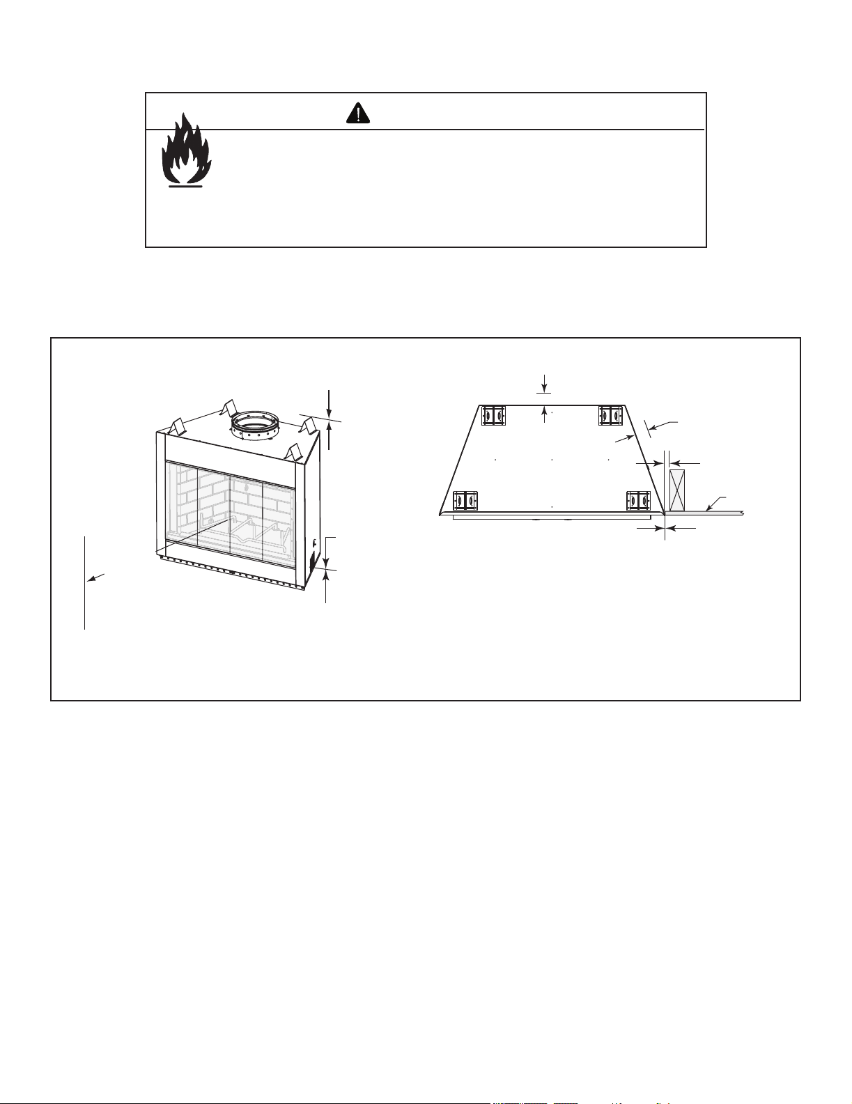
B. Typical Fireplace System
The Outdoor Lifestyle replace system consists of the fol-
lowing:
• Fireplace/integral grate/dual cooling air system
• Refractory
• Chimney termination cap
• Chimney system (SL1100 series pipe is NOT approved
for Canada)
• Hearth extension
Optional components include:
• Glass doors
• Weather cover
• SLA10 11-10 in./279-254 mm Adapter (required in
Canada)
Termination Cap
Chimney System
Refractory
Integral Grate
Hearth Extension
SLA10 not shown
Figure 2.1 Typical Fireplace System
Outdoor Lifestyles by Hearth & Home Technologies • Montana US-CAN • 4039-156 Rev R • 09/19/13
6
Before beginning the installation be sure the following tools
and building supplies are available:
Reciprocating saw Framing material
Pliers High temp caulking material
Hammer Gloves
Phillips screwdriver Framing square
Flat blade screwdriver Electric drill and bits
Plumb line Safety glasses
Level Tape measure
1/2-3/4 in. length, #6 or #8 self-drilling screws
Misc. screws and nails
• Keep replace dry.
• Mold or rust may cause odors.
CAUTION
D. Inspect Fireplace and Components
• Carefully remove the replace and components from the
packaging.
• The vent system components and doors are shipped in
separate packages.
• Report to your dealer any parts damaged in shipment.
• Read all the instructions before starting the installation.
Follow these instructions carefully during the
installation to ensure maximum safety and benet.
Fire Risk
Explosion Risk
Inspect fireplace and components for
damage. Damaged parts may impair safe
operation.
• Do NOT install damaged components.
• Do NOT install incomplete components.
• Do NOT install substitute components
Report damaged parts to dealer.
WARNING
C. Tools and Supplies Needed
Outdoor Lifestyles by Hearth & Home Technologies • Montana US-CAN • 4039-156 Rev R • 09/19/13
7
3
Framing and Clearances
A. Selecting Fireplace Location
This outdoor replace will shed moderate amounts of water,
but is not waterproof. Water and condensing water vapor
may enter the chase under certain conditions.
The replace will not perform as an exterior wall. Moisture
penetration must be considered for construction that places
the replace against structure walls or on moisture sensitive
surfaces.
• Exterior Walls (see Figure 3.1)
Hearth & Home Technologies recommends that the
replace chase be constructed outside the structure’s
weather envelope. Where the platform meets the wall, use
a ashing detail similar to that required for attached decks.
Chase platforms, including hearths, should slope away
from the structure at 1/8 in to 1/4 in. per foot. The replace
can be shimmed level. Build the outside enclosure out of
standard building materials, being careful to maintain the
minimum air clearances specied in these installation
instructions.
Fire Risk
Provide adequate clearances.
• Around air openings
• To combustibles
• For service access.
Locate replace away from trafc areas.
WARNING
Note:
• Illustrations and photos reect typical installations
and are FOR DESIGN PURPOSES ONLY.
• Illustrations/diagrams are not drawn to scale.
• Actual installation/appearance may vary due to
individual design preference.
• Hearth & Home Technologies reserves the right to
alter its products.
• Freestanding Installations (see Figure 3.2)
When installing this replace as a freestanding replace
on your porch, patio or in your yard, it must be enclosed
to prevent impact damage to the replace. The exterior
of the enclosure may be nished in a textured plywood,
a wood clapboard siding, brick, or a cultured stone. Vinyl
siding is not recommended for use on the front of the
replace due to the heat the replace produces. This can
cause the vinyl siding to deteriorate.
• When Installed on Surfaces Where Water May Collect
or Cause Damage:
Hearth & Home Technologies recommends that a drainage
pan be placed under the unit. This can be constructed
of metal, adhesive polymer membrane (such as ice
and water shield) or other suitable materials. A means
of drainage out of the pan such as tubes or weep holes
should be provided. A slope of 1/8 in. to 1/4 in. per foot
towards the drain port is suggested. The replace can be
shimmed level.
Hearths should slope away from the front of the replace
and chase at 1/8 in. to 1/4 in. per foot. Spark strips must
be used on top of any combustible hearth materials used
for moisture management.
Outdoor Lifestyles by Hearth & Home Technologies • Montana US-CAN • 4039-156 Rev R • 09/19/13
8
B
A
H
F
Note: If this surface is
inside the building’s
warm air envelope...
...then this surface
must be an exterior
wall system.
C
D
G
G
C
D
H
G
F
J
I
E
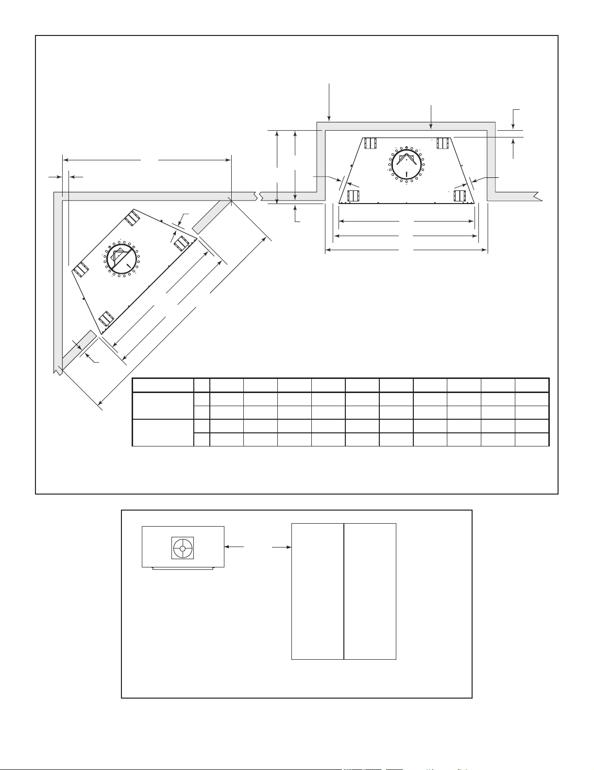
Figure 3.1 Fireplace Locations
FREESTANDING
INSTALLATION
(Combustible Structure)
(Enclosed Fireplace)
10 ft
Min.
Figure 3.2 Freestanding Fireplace Locations
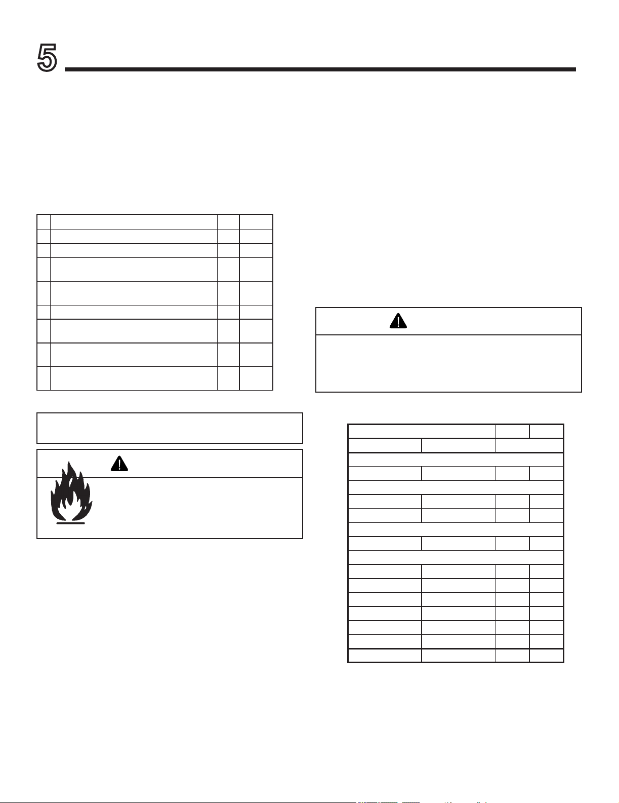
Model A B C D E F G H I J
Montana-36
in. 24-1/2 24 42 43 46 1/2 1-1/2 1-1/2 74-1/2 53-1/2
mm 622 610 1067 1092 1168 13 38 38 1892 1359
Montana-42
in. 24-1/2 24 48 49 52 1/2 1-1/2 1-1/2 80-1/2 57
mm 622 610 1219 1245 1321 13 38 38 2045 1448
Outdoor Lifestyles by Hearth & Home Technologies • Montana US-CAN • 4039-156 Rev R • 09/19/13
9
0 in.
0 in. to level
of standoffs
Combustible Object
36 in.
(914 mm)
1-1/2 in. (38 mm)
Drywall
0 in.
1/2 in. (13 mm)
1-1/2 in.
(38 mm)
B. Clearances
Figure 3.3 Clearances to Combustible Materials
Fire Risk
• Comply with all minimum clearances to combustibles as speci ed.
• Framing or nishing material used on the front of, or in front of, the
appliance closer than the minimums listed, must be constructed entirely
of noncombustible materials (i.e., steel studs, concrete board, etc.).
Failure to comply may cause re.
WARNING

Outdoor Lifestyles by Hearth & Home Technologies • Montana US-CAN • 4039-156 Rev R • 09/19/13
10
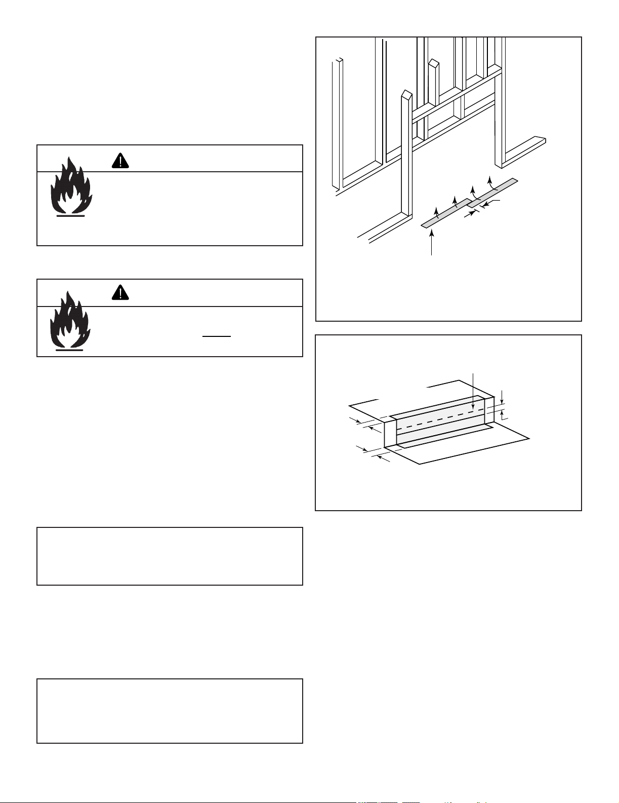
C. Sidewalls/Surrounds
Adjacent combustible side walls must be located a minimum of 12 in. (305 mm) from the replace opening. See Figure 3.4.
If you are using a decorative surround constructed of combustible material, it must be located within the shaded area de-
ned in Figure 3.3. Short stub walls are also acceptable if they are contained within the shaded area.
D. Frame the Fireplace
Figure 3.5 shows a typical framing (using 2 x 4 lumber) of the replace, assuming combustible materials are used. All re-
quired clearances to combustibles around the replace must be adhered to. See Figure 3.2. Any framing across the top of
the replace must be above the level of the top standoffs.
14-3/8 in./36.5 cm
12 in.
30.5 cm
39
deg.
4 in./10.2 cm
BRICK
FRONT
FLUSH FRONT
12 in.
30.5 cm
9-3/4 in./24.8 cm
50
deg.
A
B
Cat # A B
MONTANA-36 & 36H 36 in./91.4 cm 42 in./106.7 cm
MONTANA-42 & 42H 42 in./106.7 cm 48 in./121.9 cm
Figure 3.4 Sidewalls and Surrounds
Figure 3.5 Framing the Fireplace
2 in./51 mm
minimum air
space clearance
to the enclosure.
Use only noncombustible
material below the top of
the top standoffs.
24-1/8 in.
61.3 cm
42-3/8 in.
107.6 cm
A
CAT. # A
MONTANA-36 & 36H 43 in./109 cm
MONTANA-42 & 42H 49 in./124 cm
Outdoor Lifestyles by Hearth & Home Technologies • Montana US-CAN • 4039-156 Rev R • 09/19/13
11
E. Chimney Requirements
When planning your replace location, the chimney construc-
tion and necessary clearances must be considered. The re-
place system and chimney components have been tested to
provide exibility in construction. The following gures are
the minimum distances from the base of the replace.
• Minimum overall straight height is 6 ft 4 in. if the replace
is freestanding and a minimum of 10 ft from a combustible
structure. See Figure 3.2.
• Chimney must extend 2 ft (.6 m) above any portion
of the roof within 10 ft (3 m) of the chimney. Refer to
Figure 6.1.
Note: A maximum of two pairs of offsets and returns may
be used.
ft m
• Minimum height width offset/return 16 4.88
• Maximum height 90 27.43
• Maximum chimney length between an offset
and return
20 6.1
• Maximum distance between chimney
stabilizers
35 10.67
• Double offset/return minimum height 24 7.32
• Maximum unsupported chimney length
between the offset and return
6 1.83
• Maximum unsupported chimney height above
the replace
35 10.67
• Minimum overall straight height if replace is
freestanding
6.4 3.048
Outdoor Lifestyles by Hearth & Home Technologies • Montana US-CAN • 4039-156 Rev R • 09/19/13
12
72 in./183 cm
min.
TR11/TR444
Termination
Cap
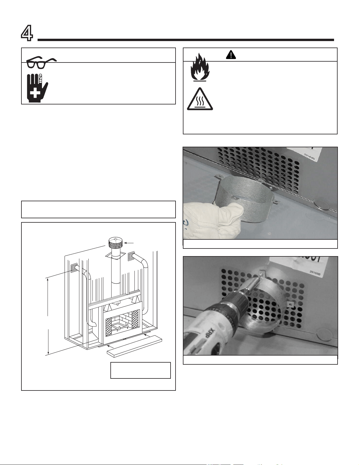
A. Install the Dual Cooling Air Kit
The cooling air kit is supplied as a standard feature with this
replace and is required for safe operation. Installation must
be done at the time of initial construction. The cooling air in-
let tubes must be a minimum of 72 in. (1829 mm) above the
base of the replace to prevent potential blockage by snow
or yard debris. See Figure 4.1.
To install the air kit collar, slide one of the tabs down into the
seam. See Figure 4.2. Secure the collar tabs to the replace
with screws placed into the holes provided. See Figure 4.3.
Repeat for other side.
Sharp Edges
• Wear protective gloves and safety glasses
during installation.
CAUTION
4
Installation of Fireplace
Fire Risk
Asphyxiation Risk
Do not draw outside combustion air from:
• Wall, oor or ceiling cavity.
• Enclosed space such as an attic or
garage.
• Close proximity to exhaust vents or
chimneys.
Fumes or odor may result.
WARNING
Figure 4.1 Cooling Air Location
Figure 4.2 Slide the Tabs
Figure 4.3 Secure the Tabs
Note: The cooling air kit must terminate at least 6 ft. (1.83 m)
above ground level.
11-10 in./279-254 mm
adapter not shown
Outdoor Lifestyles by Hearth & Home Technologies • Montana US-CAN • 4039-156 Rev R • 09/19/13
13
B. Secure the Fireplace
• Position the Fireplace
This replace may be placed on either a combustible or
noncombustible continuous at surface. Follow the in-
structions for framing in Section 3.D. Slide the replace
into position. Be sure to provide the minimum air clear-
ance at the sides and back of the replace assembly.
See Section 3.B.
Included with your replace you will nd two metal
hearth strips measuring approximately 26 in. x 4 in.
(660 mm x 102 mm). These strips are used to provide
added protection where the replace and the hearth ex-
tension meet.
Slide each metal strip 2 in. (51 mm) under the front
edge of the replace. The individual pieces must over-
lap each other by 1 in. (25 mm) minimum in the middle
of the replace to provide continuous coverage of the
oor. See Figure 4.4. These metal strips should extend
from the front and sides of the replace opening by 2 in.
(51 mm).
Note: When elevating the fireplace above the hearth
extension the front of the elevated platform must be
protected with a protective metal hearth strip as shown in
Figure 4.5.
Raised Platform
Floor
2 in.
(51 mm)
1 in. (25 mm) min.
overlap
2 in.
(51 mm)
Top piece must overlap
bottom piece
Figure 4.5 Protect the Front of an Elevated Platform
• Level the Fireplace
Level the replace side-to-side and front-to-back. Shim
with noncombustible material, such as sheet metal, as
necessary. Secure the replace (using the nailing ang-
es located on either side of the replace) to the vertical
framing.
Important: To ensure proper t of the glass doors, check
the fireplace opening for square. Measure diagonal
distances of the opening to make sure they are equal.
If they are not, continue to shim the replace until those
diagonals are equal.
Protective metal strips are placed 2 in. (51 mm) under the
front of the fireplace and must extend beyond the front
and sides of fireplace opening by 2 in. (51 mm).
1 in. (25 mm)
overlap
Figure 4.4 Position the Protective Metal Hearth Strips
• Place the Protective Metal Hearth Strips
Fire Risk!
• Prevent contact with sagging, loose
insulation.
• Do NOT install against vapor barriers or
exposed insulation.
WARNING
Fire Risk!
• Metal hearth strips MUST be installed.
Sparks or embers may ignite ooring.
WARNING
Outdoor Lifestyles by Hearth & Home Technologies • Montana US-CAN • 4039-156 Rev R • 09/19/13
14
A. Chimney Requirements
Vertical distances are measured from the base of the re-
place.
• Minimum overall straight height is 6 ft 4 in. if the replace
is freestanding and a minimum of 10 ft from a combustible
structure. See Figure 3.2.
• Chimney must extend 2 ft (.6 m) above any portion
of the roof within 10 ft (3 m) of the chimney. Refer to
Figure 6.1.
To determine the chimney components needed to complete
your particular installation, follow the steps below:
• Determine the total vertical height of the fireplace
installation. This dimension is measured from the base of
the replace assembly to the point where the smoke exits
the termination cap.
• Subtract the effective height of the replace assembly from
the overall height of the replace installation (measured
from the base of the fireplace to the bottom of the
termination cap).
• Refer to Table 5.1 to determine what components must
be selected to complete the replace installation.
• Determine the number of ceiling restops, stabilizers,
roof flashing, etc. required to complete the fireplace
installation.
Table 5.1
• Do NOT connect this fireplace to a chimney flue
servicing another appliance.
• Do NOT connect to any air distribution duct or
system.
CAUTION
Fire Risk
• Must maintain 2 in. (51 mm) air clearance
to insulation and other combustible
materials.
WARNING
Note: A maximum of two pairs of offsets and returns may
be used.
5
Chimney Assembly
ft m
• Minimum height width offset/return 16 4.88
• Maximum height 90 27.43
• Maximum chimney length between an offset
and return
20 6.1
• Maximum distance between chimney
stabilizers
35 10.67
• Double offset/return minimum height 24 7.32
• Maximum unsupported chimney length
between the offset and return
6 1.83
• Maximum unsupported chimney height above
the replace
35 10.67
• Minimum overall straight height if replace is
freestanding
6.4 3.048
HEIGHT OF CHIMNEY COMPONENTS in. mm
US Canada ONLY
Chimney Stabilizer
SL11 SL4 4-3/4 121
Ceiling Firestops
FS538 FS538 0 0
FS540 FS540 0 0
Offsets/Returns
SL1130 SL430 14-1/2 368
Chimney Sections*
SL1106 SL406 4-3/4 121
SL1112 SL412 10-3/4 273
SL1118 SL418 16-3/4 425
SL1136 SL436 34-3/4 883
SL1148 SL448 46-3/4 1187
n/a SLA10 16-3/4 425
* Dimensions reect effective height.
Outdoor Lifestyles by Hearth & Home Technologies • Montana US-CAN • 4039-156 Rev R • 09/19/13
15
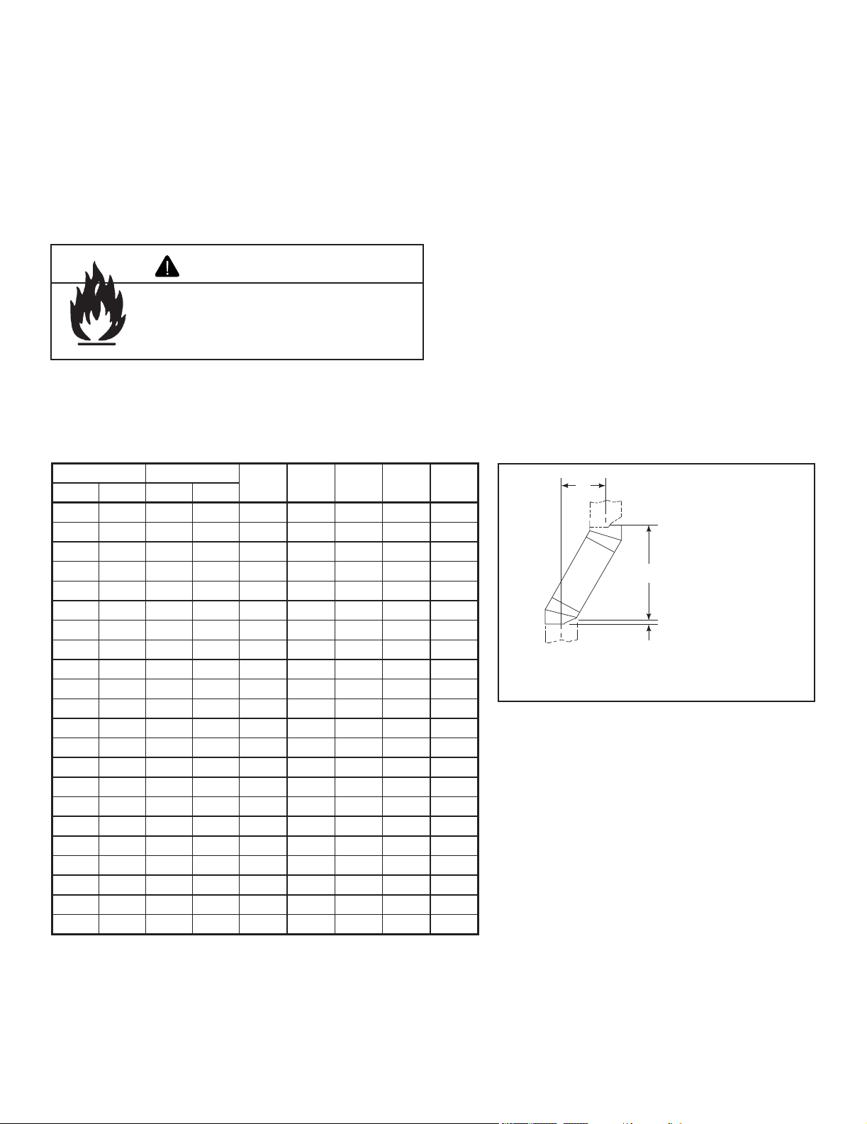
B. Using Offsets/Returns
To bypass any overhead obstructions, the chimney may be
offset using an offset/return.
An offset and return may be attached together or a chimney
section(s) may be used between an offset and return.
Perform the following steps to determine the correct chim-
ney component combination for your particular installation:
• Measure how far the chimney needs to be shifted to enable
it to avoid the overhead obstacle. See Figure 5.1. Use
dimension “A” to determine chimney section required to
achieve the needed shift.
• After determining the offset dimension, refer to Table 5.2
and nd the “A” dimension closest to but not less than the
distance of shift needed for your installation.
• The “B” dimension that coincides with the “A” dimension
represents the required vertical clearance that is needed
to complete the offset and return.
• Read across the chart and nd the number of chimney
sections required and the model number of those particular
chimney parts.
• Whenever the chimney penetrates a oor/ceiling, a ceiling
restop must be installed.
• The effective height of the replace assembly is measured
from the base of the replace to the top of the starter collar.
See Dimensions in Section 12.
Table 5.2
A
B
1-1/4 in. (32 mm)
OVERLAP
Figure 5.1 Chimney Offset/Return
Example: Your “A” dimension from Figure 5.3 is
14 1/2 in. (368 mm). Using Table 5.2 the dimension
closest to, but not less than 14 1/2 in. (368 mm) is
15 3/4 in. (400 mm) using a 30° offset/return. It is
then determined from the table that you would need
36 5/8 in. (930 mm) (Dimension “B”) between the
offset and return. The chimney components that best
t your application are two SL1112s or SL412s.
Fire Risk
• Draft will be restricted if offsets/returns
greater than 30° are used.
WARNING
A B
SL1106
SL406
SL1112
SL412
SL1118
SL418
SL1136
SL436
SL1148
SL448in. mm in. mm
4 7/8 124 17 7/8 454 - - - - -
7 1/4 184 2 2 559 1 - - - -
9 3/4 248 26 1/8 664 2 - - - -
10 1/4 260 27 1/4 692 - 1 - - -
12 3/4 324 31 3/8 797 1 1 - - -
13 1/4 337 32 3/8 822 - - 1 - -
15 3/4 400 36 5/8 930 - 2 - - -
18 1/8 460 40 3/4 1035 1 2 - - -
18 3/4 476 41 3/4 1060 - 1 1 - -
21 3/4 552 47 1194 - - 2 - -
22 1/4 565 48 1219 - - - 1 -
24 3/4 629 52 1/8 1324 1 - - 1 -
27 3/4 705 57 3/8 1457 - 1 - 1 -
28 1/4 718 58 3/8 1483 - - - - 1
30 3/4 781 62 1/2 1588 1 - - - 1
33 3/4 857 67 3/4 1721 - 1 - - 1
36 3/4 933 73 1854 - - 1 - 1
39 3/4 1010 78 1/8 1984 - - - 2 -
41 1/8 1045 82 3/8 2092 1 - - 2 -
45 3/4 1162 88 1/2 2248 - - - 1 1
48 1/8 1222 92 3/4 2356 1 - - 1 1
51 3/4 1314 98 7/8 2511 - - - - 2
Proper assembly of air cooled chimney parts results in an overlap of chimney joints
of 1-1/4 in. (32 mm). Effective length is built into this table.
Outdoor Lifestyles by Hearth & Home Technologies • Montana US-CAN • 4039-156 Rev R • 09/19/13
16
C. Assemble the Chimney Sections
Attach either a straight chimney section or an offset to the
top of the replace (depending on your installation require-
ment). Chimney sections are locked together by pushing
downward until the top section meets the stop bead on the
lower section.
The inner ue is placed to the inside of the ue section below
it. The outer casing is placed outside the outer casing of the
chimney section below it. See Figure 5.2.
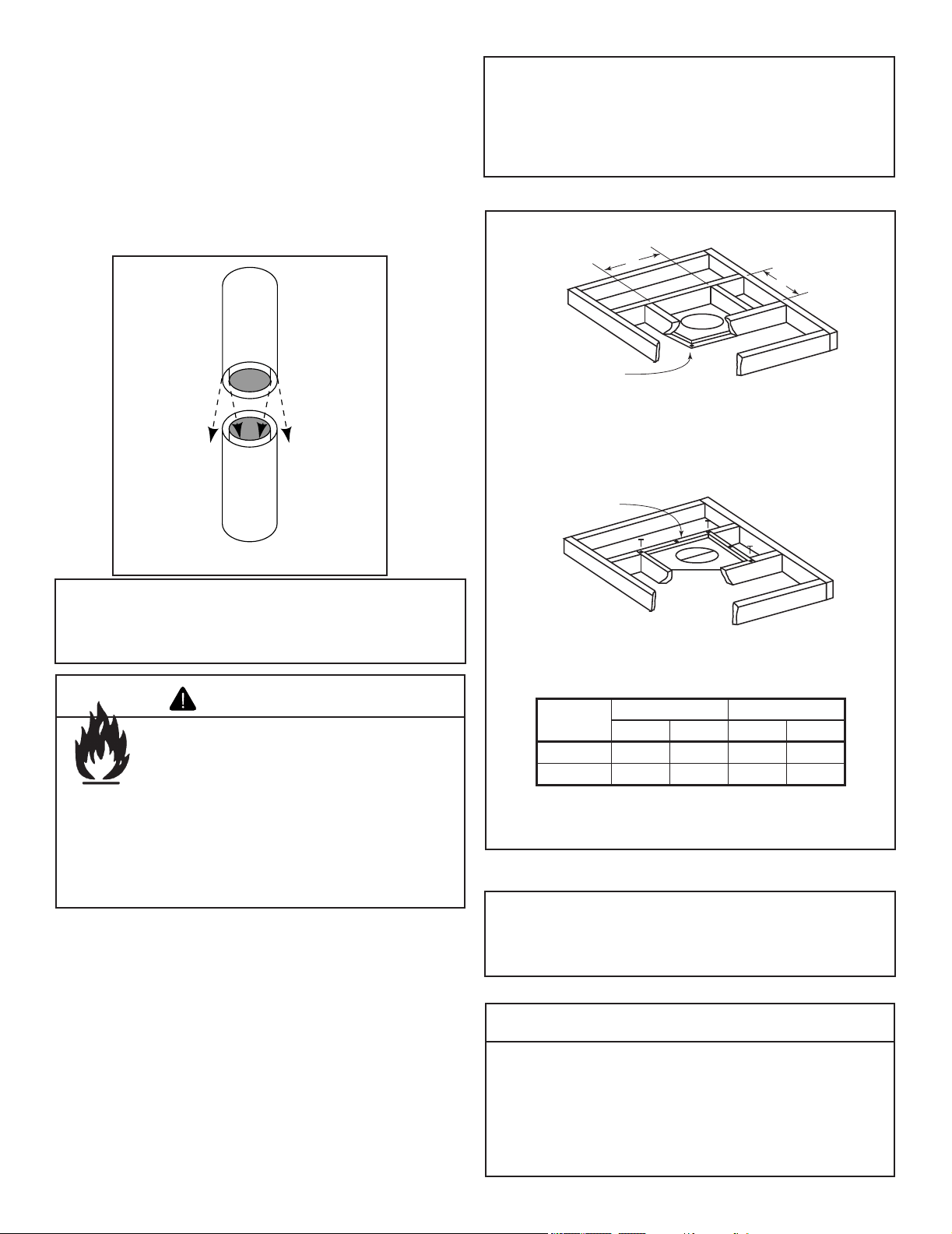
D. Install the Ceiling Firestops
Where the chimney system is installed in a chase on the
exterior side of the building envelope or as a free standing
installation, restops are not required. Check building codes
prior to installation.
Where the chimney system is on the interior side of the build-
ing envelope, follow the ceiling restop instructions below:
• Mark and cut an opening in the ceiling for the ceiling
restop being used. See Figure 5.3.
• Frame the opening with the same size lumber used in the
ceiling joists.
• Install the ceiling restop.
Note: The ceiling restop MUST be nailed to the bottom
of the ceiling joists EXCEPT when the space above is
uninsulated and the attic insulation shield is not being used
(see Figure 5.5). When the attic insulation shield is used
the ceiling restop may be above or below the joist of an
insulated ceiling.
Note: You must provide support for the pipe during
construction and check to be sure inadvertent loading has
not dislodged the chimney section from the replace or at
any chimney joint.
Note: Inner flue and outer liner sections cannot be
disassembled once locked together. Plan ahead to ensure
the proper installation height is achieved with the selected
chimney components.
• Ceiling restops must be used where chimney pipe
penetrates ceiling/oor.
Ceiling restop slows spread of re and reduces cold air
inltration.
CAUTION
Figure 5.2 Assembling Chimney Sections
Fire Risk
Do NOT install substitute or damaged
chimney components.
• MUST use chimney system described in
this manual.
• NO OTHER chimney components may
be used.
Substitute or damaged chimney components
may impair safe operation.
WARNING
ROOM ABOVE (non-insulated ceiling)
ATTIC ABOVE (insulated ceiling)
B
A
Ceilng firestop from
bottom
Ceiling firestop from
top
Note: Use same dimensional lumber for framing
ceiling firestop and joists.
Figure 5.3 Installing the Ceiling Firestop
Catalog #
A B
in. mm in. mm
FS538 17 432 17 432
FS540 17 432 26 660
►
Outdoor Lifestyles by Hearth & Home Technologies • Montana US-CAN • 4039-156 Rev R • 09/19/13
17
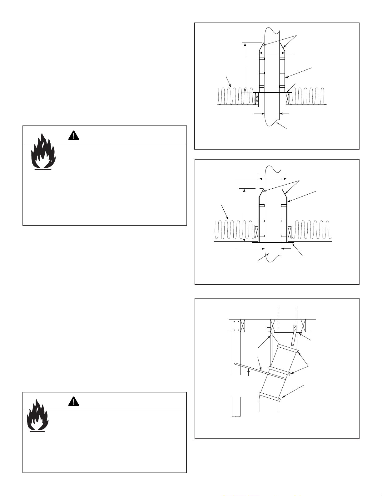
E. Install the Attic Insulation Shield
An insulation shield must be installed when there is a pos-
sibility of insulation coming into contact with the factory built
chimney system.
• Bend the tabs at the top of the attic insulation shield inward.
This will help keep the chimney section centered in the
shield.
• Position the shield over the vertical chimney section where
it penetrates a ceiling restop.
• Slide the shield down until it rests on the ceiling restop.
The ceiling restop will support the insulation shield. See
Figures 5.4 and 5.5.
F. Double-check the Chimney Assembly
Continue assembling the chimney sections up through the
ceiling restops as needed. While doing so, be aware of the
height and unsupported chimney length limitations given un-
der Section 5.A. Chimney Requirements.
Check each section by pulling up slightly from the top to en-
sure proper engagement before installing the succeeding
sections. If they have been connected correctly, they will not
disengage when tested.
G. Secure the Chimney
When offsets and returns are joined to straight pipe sections,
they must be locked into position with the screws provided*
(outer only), using the predrilled holes. To prevent gravity
from pulling the chimney sections apart, the returns and the
chimney stabilizers have hanger straps for securing these
parts to joists or rafters. See Figure 5.6.
* or equivalent #6 or #8 sheet metal screw no longer than
3/4 in. (19 mm).
24 in.
(610 mm)
Attic
Insulation
Shield
Chimney
Insulation
13 in.
(330 mm)
17 in.
(423 mm)
Ceiling Firestop
Tabs
Figure 5.4 Install Attic Insulation Shield Above the Ceiling
Attic
Insulation
Shield
Chimney
Insulation
Ceiling Firestop
Tabs
24 in.
(610 mm)
13 in.
(330 mm)
17 in.
(423 mm)
Figure 5.5 Install Attic Insulation Shield Below the Ceiling
Ceiling
Firestop
Straps
Optional
Additional
Support
Joint
Band
(Optional)
Figure 5.6 Secure the Chimney
Fire Risk
• DO NOT pack insulation or other
combustibles: between ceiling restops;
between chimney and attic insulation
shield.
• ALWAYS maintain specied clearances
around chimney and ceiling restops.
• Install ceiling restops as specied.
Failure to keep insulation or other material
away from chimney pipe may cause re.
WARNING
Fire Risk
• Secure offsets with screws (not to exceed
3/4 in./19 mm in length).
WARNING
• Secure returns with strapping.
• Straight chimney sections may be secured with screws
(not to exceed 3/4 in./19 mm in length) at the joints.
Keep chimney sections from separating or twisting.
Outdoor Lifestyles by Hearth & Home Technologies • Montana US-CAN • 4039-156 Rev R • 09/19/13
18
6
Complete the Enclosure
Figure 6.1 Multiple Chimneys
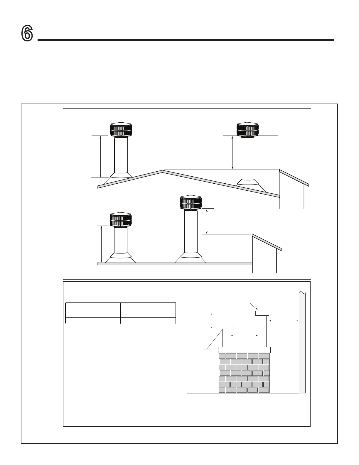
A. Chimney Termination
Chimney Termination Requirements (See Figure 6.1)
• Must have a cap approved and listed for this replace system
• Must not be located where it will become plugged by snow or other material
• Must terminate at least 3 ft (914 mm) above the roof and at least 2 ft (610 mm) above any portion of the roof within 10 ft
(3.05 m)
• Must be located away from trees or other structures
Slanted Roofs
Flat Roofs
Chimney must
extend 3 ft (.9 m)
above the roof
Chimney must extend 2 ft (.6 m)
above any portion of the roof or
adjacent structures within
10 ft (3 m) of the chimney
Chimney must
extend 3 ft (.9 m)
above the roof
Chimney must extend 2 ft (.6 m)
above any portion of the roof or
adjacent structures within
10 ft (3 m) of the chimney
Multiple Chimney Locations
A B
6 in. (minimum) up to 20 in.
152 mm/508 mm
18 in. minimum
457 mm
20 in. and over 0 in. minimum
Gas, Wood or Fuel Oil
Termination Cap
Wood
Minimum
(See
illustration
above)
B
Gas
Termination
Cap **
A *
Perpendicular Wall
*
If using decorative cap cover(s), this distance may need to be
increased. Refer to the installation instructions supplied with the
decorative cap cover.
**
In a staggered installation with both gas and wood terminations, the
wood termination cap must be higher than the gas termination cap.
Outdoor Lifestyles by Hearth & Home Technologies • Montana US-CAN • 4039-156 Rev R • 09/19/13
19
Termination Cap
Storm Collar
Slope Downward
Turn-down
Drip Edge
Chase
(Chimney)
2 in. (51 mm) Collar
on Chase Top
Caulk
.018 (26 ga) min.
Galvanized
Chase Top
Figure 6.3 Chase Top Construction
B. Chase Top
A metal chase top is required to seal the top of the chase
around the chimney pipe. The top should include a turn-
down and drip edge to prevent water from seeping into the
chase. Provide a 1/8 in. (3 mm) gap around the ue pipe
and slope the top downward away from the penetration. See
Figure 6.3.
• All seams must be caulked to prevent leaks.
• A chase installation must use a chase top. Chase tops
are available from your Hearth & Home dealer or may be
eld constructed.
• Attach the chase top to the top of the chase.
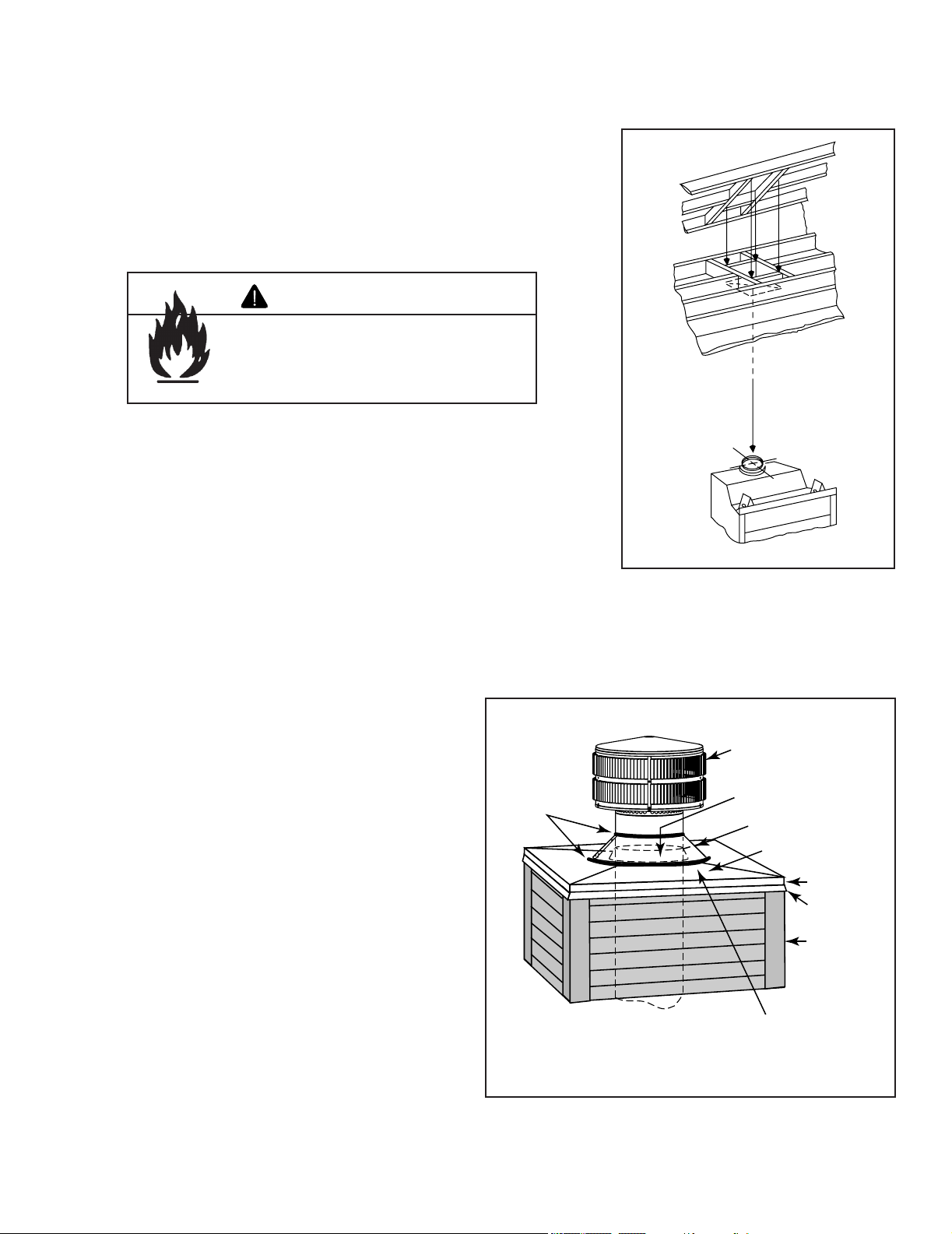
Figure 6.2 Ceiling/Attic Construction
Fire Risk
• Must maintain 2 in. (51 mm) air clearance
to insulation and other combustible
materials.
WARNING
Mark the Exit Point of the Roof
Locate the point where the chimney will exit the roof by plumbing down to the
center of the chimney. Drive a nail up through the roof to mark the center. See
Figure 6.2.
Cut Out the Hole in the Roof
Measure to either side of the nail and mark the 14-1/2 in. x 14-1/2 in.
(368 mm x 368 mm) opening required. This is measured on the horizontal;
actual length may be larger depending on the pitch of the roof. Cut out and
frame the opening. See Chapter 25 of the Uniform Building Code for roof
framing details.
Assemble the Chimney Sections Through the Roof
Continue to add chimney sections through the roof opening, maintaining at
least a 2 in. (51 mm) air space to combustible materials.
Install the Roof Flashing
If a roof ashing is to be used, install the roof ashing appropriate to the
roof pitch and install a round termination cap and storm collar following the
instructions shipped with the cap.
Outdoor Lifestyles by Hearth & Home Technologies • Montana US-CAN • 4039-156 Rev R • 09/19/13
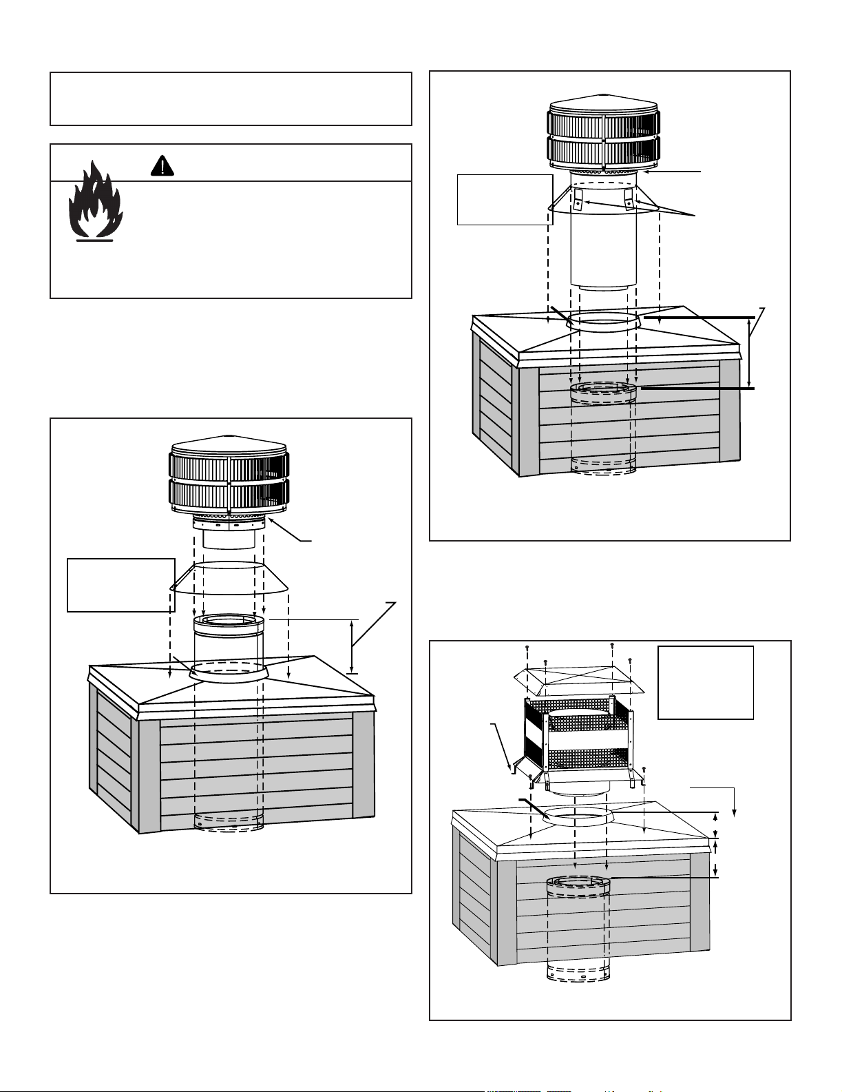
20
Note: To protect against the effect of corrosion on those
parts exposed to the weather, the termination cap can be
painted with a rust-resistant paint.
Fire Risk
• The minimum overlap of cap to pipe
MUST be met or chimney may separate
from cap.
Separation allows sparks, heat and embers
to escape.
WARNING
C. Install the Termination Cap
Install the chimney sections up through the chase enclosure
and refer to termination cap instructions.
Storm
Collar
Chimney
Pipe
Chase Top
Termination
Cap
Chase
6 in. (153 mm)
Minimum top of
chase to top of
chimney pipe
Collar
2 in. (51 mm)
Minimum Height
Do NOT
block air holes
Caulk gaps between
storm collar & pipe,
and storm collar
& chase top.
Termination cap pipe and chimney section must be snapped
together to maintain an overlap of 1-1/2 in. (38 mm).
Slip
storm collar
around chimney pipe
before termination
cap pipe is snapped
into the chimney
pipe.
Figure 6.4 Installing a TR11/TR444 Round Termination Cap
• TR11/TR444 Round Termination Cap
Storm
Collar
Chimney
Pipe
Chase Top
Termination
Cap
Chase
14 1/2 in. (368 mm)
Maximum
Collar
2 in. (51 mm)
Minimum Height
Caulk gaps between
storm collar & pipe,
and storm collar
& chase top.
Do NOT
block air
holes
3 clip brackets.
Slip over chase collar
and attach with screws
provided.
Termination cap pipe and chimney section must overlap 1-1/2 in. (38 mm)
Assemble
storm collar
around extended
termination cap
pipe
once cap is
installed.
• TR11T/TR442 Round Telescoping Termination Cap
Figure 6.5 Installing a TR11T/TR442 Round Telescoping Termina-
tion
Cap
Chimney
Pipe
Chase Top
Termination Cap
Chase
Collar
2 in. (51 mm)
Minimum Height
Place waterproof
caulk or sealer under
each flange of the
termination cap and
on top of each screw
to help prevent leaks.
Flange
Termination cap pipe and chimney section must overlap 1-1/2 in. (38 mm)
2 in. (51 mm)
maximum
4 3/4 in. (121 mm)
maximum
The last section of pipe
must stop between 2 in. (51
mm) above the top of the
chase and 4 3/4 in. (121
mm) below the top of the
chase.
• ST1175/ST475 Square Termination Cap
Figure 6.6 Installing an ST1175/ST475 Square Termination Cap
Outdoor Lifestyles by Hearth & Home Technologies • Montana US-CAN • 4039-156 Rev R • 09/19/13
21
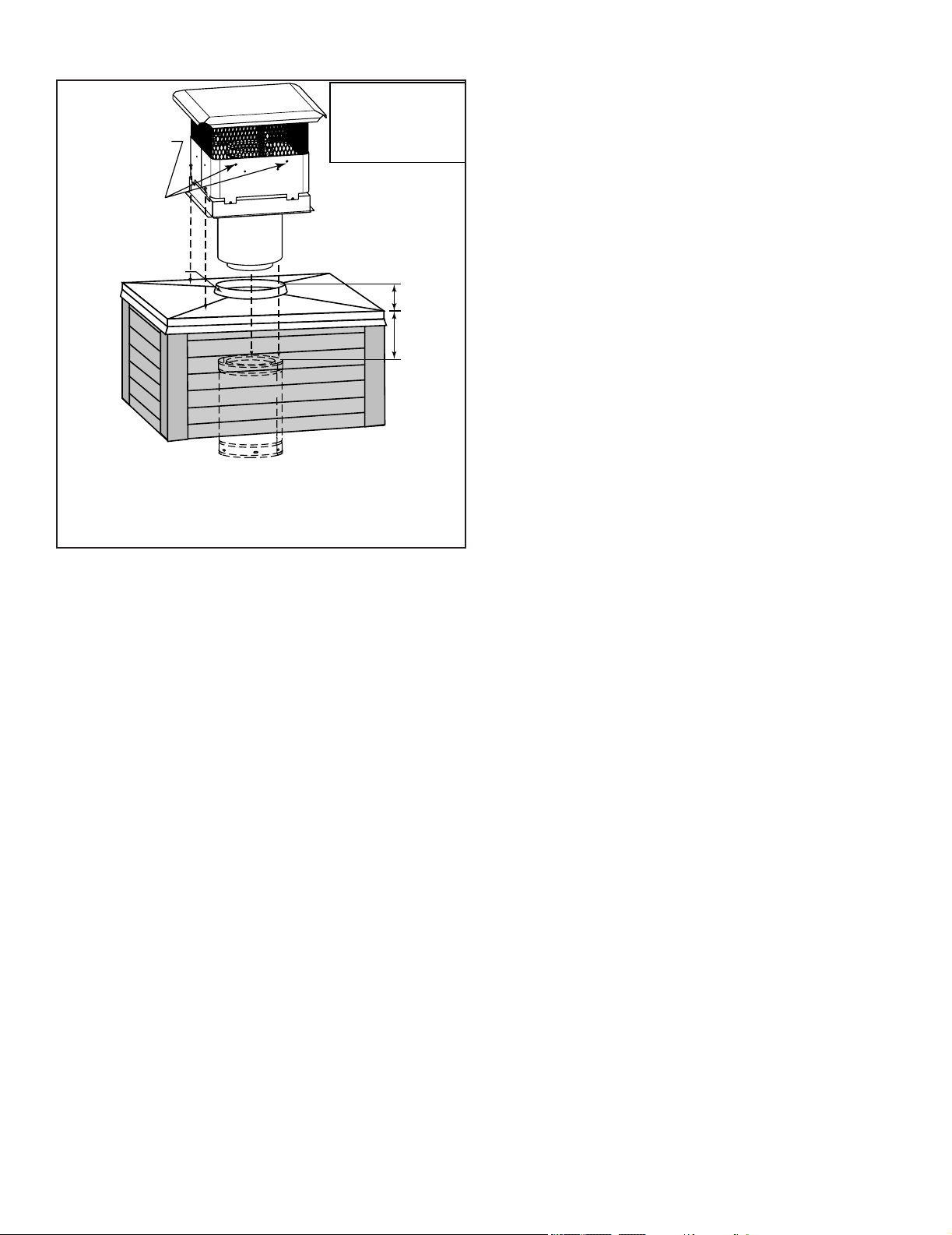
• TCT1175 Terra Cotta Cap
Chimney
Pipe
Chase Top
Termination Cap
Chase
Collar
2 in. (51 mm)
Minimum Height
Remove 2 screws
from front & back
to lift the top off
Termination cap pipe and chimney section must overlap
1-1/2 in. (38 mm)
Place waterproof sealer
under each flange of the
termination cap and on
top of each screw to
help prevent leaks.
The last section of pipe
must stop between 2 in.
(51 mm) above top of
chase and 7 in. (178 mm)
below top of chase
2 in. (51 mm)
7 in. (178 mm)
Figure 6.7 Installing a TCT1175 Terra Cotta Cap
Outdoor Lifestyles by Hearth & Home Technologies • Montana US-CAN • 4039-156 Rev R • 09/19/13
22
A. Gas Log/Lighter Provisions
A certied gas log lighter or decorative gas log set can be
installed in this replace.
This replace was not tested and listed for use with an un-
vented gas log heater. Do not install an unvented gas log
heater in this replace and operate it with the ue damper in
the closed position unless the unvented gas log heater has
been specically tested and listed for use in this replace by
Underwriters Laboratories Inc.
Use of an unvented gas log heater in this factory built
replace may create a re hazard that can result in a
structure re.
• Maximum input is 100,000 BTU/hr.
• Decorative gas appliance must be certied to ANSI Z21.60
“Standard for Decorative Gas Appliances for Installation
in Vented Fireplaces”.
• Must be installed in accordance with the National Fuel
Gas Code, ANSI Z223.1.
• A log set must incorporate a gas shutoff.
• Log set requires the damper to be locked fully open.
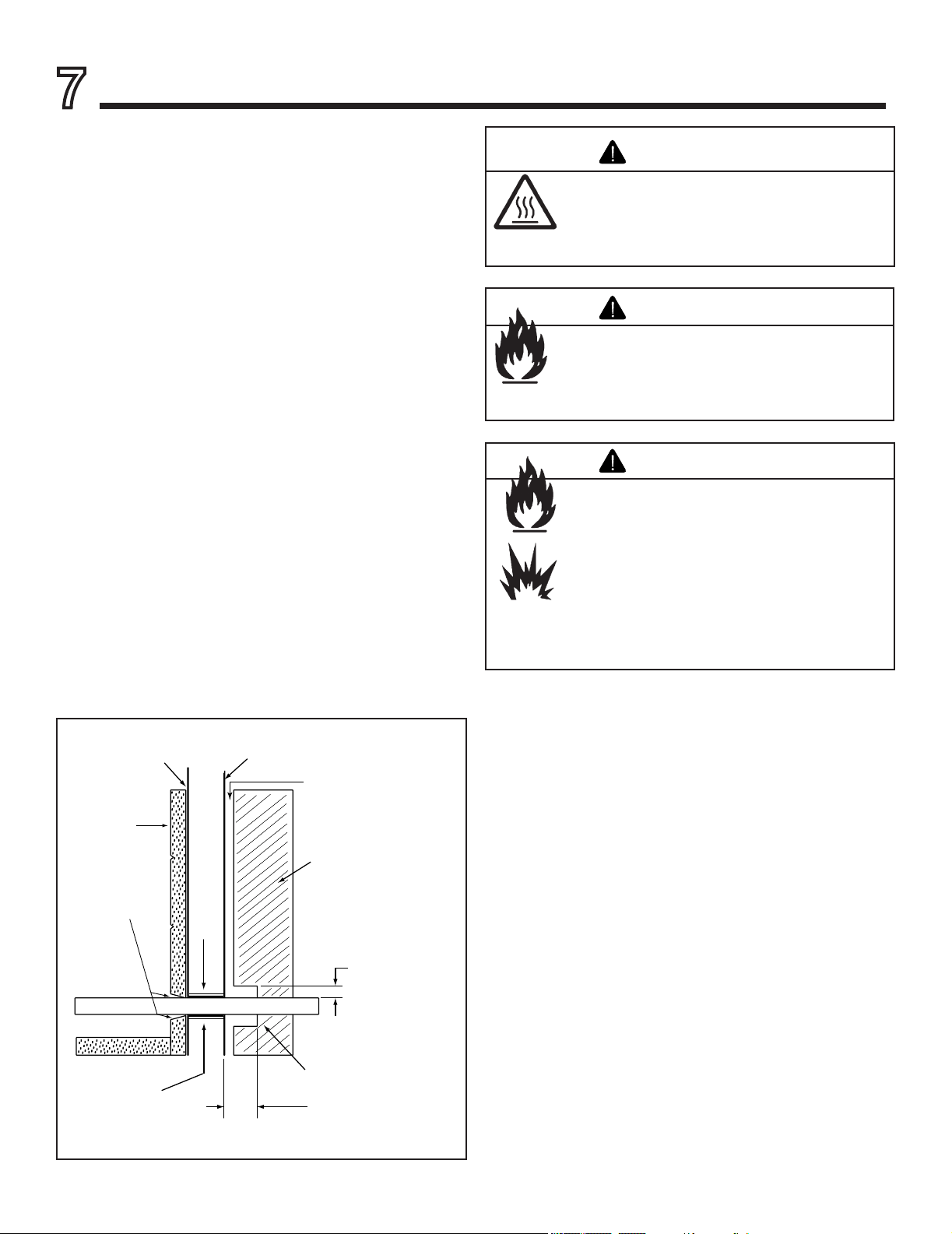
Knockouts are provided on both sides of the replace and in
refractories for 1/2 in. (13 mm) iron pipe.
• We recommend you seal refractory around pipe with
replace mortar or high temperature, noncombustible
sealant.
• Repack insulation from the knockout around the pipe.
• Maintain 1-1/2 in. (38 mm) air space around the pipe for
4 in. (102 mm) beyond the replace.
• See Figure 7.1.
Firebox
Repack
insulation
knockout
Combustible
materials
Maintain air clearance
to combustibles.
Gas line
Combustible materials
may be located at zero
clearance to gas line
beyond 4 in. (102 mm)
from fireplace side.
Gas line
1 1/2 in. (38 mm)
air space around
pipe
Refractory
Seal with
fireplace mortar
or non-combust-
ible sealant
4 in.
(102 mm)
Outer shell
of fireplace
Figure 7.1 Gas Line Installation
7
Accessories
Asphyxiation Risk
• Damper must be locked open when gas logs
installed.
Gas re generates fumes.
WARNING
Fire Risk
• For use with solid wood fuel or decorative
gas appliance only.
• DO NOT install unvented gas logs.
WARNING
Fire Risk
Explosion Risk
Inspect appliance and components for
damage. Damaged parts may impair safe
operation.
• Do NOT install damaged components.
• Do NOT install incomplete components.
• Do NOT install substitute components
Report damaged parts to dealer.
WARNING
Outdoor Lifestyles by Hearth & Home Technologies • Montana US-CAN • 4039-156 Rev R • 09/19/13
23
8
Finishing
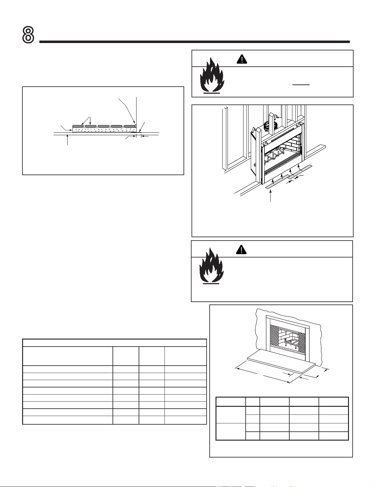
A. Hearth Extension
A hearth extension must be installed with all replaces to
protect the combustible oor in front of the replace from
both radiant heat and sparks. See Figures 8.1 -8.3.
2 in. (51 mm)
required
Continuous,
non-combustible sealant
Tile, stone or other
non-combustible material
Floor constructed of wood or
other combustible material
1/2 in. Micore
Hearth Ext
or equivalent
insulation
(see Table 11.2)
Fireplace
Protective
Metal Hearth
Strip
Figure 8.1 Hearth Extension Construction
Protective metal strips are placed 2 in. (51 mm) under the
front of the fireplace and must extend beyond the front
and sides of fireplace opening by 2 in. (51 mm).
1 in. (25 mm)
overlap
Figure 8.2 Positioning the Protective Metal Hearth Strips
The hearth extension should slope away from the front of the
replace and chase at 1/8 in. to 1/4 in. per foot. Spark strips
must be used on top of any combustible hearth materials
used for moisture management.
This replace has been tested and approved for use with a
hearth extension insulated to a minimum R value of 1.03.
To substitute materials for the factory-available hearth ex-
tensions, see Figure 8.3 and calculate insulation alterna-
tives as per Table 8.1 and the following formulas:
• Thermal conductivity per inch thickness = k
• k = (BTU)(inch) / (foot
2
)(hour)(°F)
• Required thickness = Rk
• Thermal resistance per inch thickness = r
• r = (foot
2
)(hour)(°F) / (BTU)(inch)
• Required thickness = R / rB.
A
B
C
Figure 8.3 Hearth Extension Dimensions
Fire Risk
• Metal hearth strips MUST be installed.
Sparks or embers may ignite ooring.
WARNING
Fire Risk
• Hearth extensions must be installed
exactly as specied.
High temperatures or hot embers may ignite
concealed combustibles.
WARNING
Table 8.1
CAT. # A B C
HX3 in 52 16 8
mm 1321 406 203
HX4 in 66 20 12
mm 1676 508 305
Hearth Extension Insulation Alternatives-Total minimum R Value must equal 1.03
Material
k per inch
thick
r per inch
thick
Minimum
thickness
required
Hearth & Home HX3, HX4 (Micore 300™) 0.49 2.06 1/2 in.
USG Micore 160™ 0.39 2.54 1/2 in.
USG Durock™ Cement Board 1.92 0.52 2 in.
Cement Mortor 5.0 0.20 5-1/8 in.
Common Brick 5.0 0.20 5-1/8 in.
Ceramic Tile 12.50 0.08 12-1/4 in.
Armstrong™ Privacy Guard Plus 0.46 2.18 1/2 in.
Marble 14.3-20.0 0.07-0.05 14-5/8 in. - 20-3/8 in.
Outdoor Lifestyles by Hearth & Home Technologies • Montana US-CAN • 4039-156 Rev R • 09/19/13
24
B. Finishing Material
• Combustible Material
Material which is made of or surfaced with wood,
compressed paper, plant bers, plastics, or any material
capable of igniting and burning, whether ame proofed or
not, plastered or not plastered.
• Non-Combustible Material
Material which will not ignite and burn. Such materials are
those consisting entirely of steel, iron, brick, tile, concrete,
slate, glass or plasters, or any combination thereof.
• Non-Combustible Sealant Material
Sealants which will not ignite and burn: Rutland, Inc.
Fireplace Mortar #63, Rutland 76R, Nuflex 304, GE
RTV106 or GE RTV116 (or equivalent).
After completing the framing and applying the facing material
(drywall) over the framing, a bead of non-combustible seal-
ant must be used to close off any gaps at the top and sides
between the replace and facing to prevent cold air leaks.
Large gaps can be bridged with berglass rope gasket.
Only non-combustible materials may be used to cover the
black metal replace front.
14-3/8 in./36.5 cm
12 in.
30.5 cm
39
deg.
4 in./10.2 cm
BRICK
FRONT
FLUSH FRONT
12 in.
30.5 cm
9-3/4 in./24.8 cm
50
deg.
A
B
Cat # A B
MONTANA-36 & 36H 36 in./91.4 cm 42 in./106.7 cm
MONTANA-42 & 42H 42 in./106.7 cm 48 in./121.9 cm
Figure 8.5 Sidewalls/Surrounds
Fire Risk
Do NOT obstruct air inlet or outlet grilles.
Do NOT modify grilles.
• Modifying or covering grilles could cause
temperature rise and re hazard.
Finishing materials must not interfere with:
• Air ow through grilles or louvers
• Operation of louvers or doors
• Access for service
WARNING
Fire Risk
Finish all edges and fronts to clearances and
specications.
• Metal replace front may be covered with
non-combustible material only.
• Do NOT overlap combustible materials onto
replace front.
• Install combustible materials up to specied
clearances on top front and side edges.
• Seal joints between the nished wall and
replace top and sides using only a 300° F
minimum sealant.
WARNING
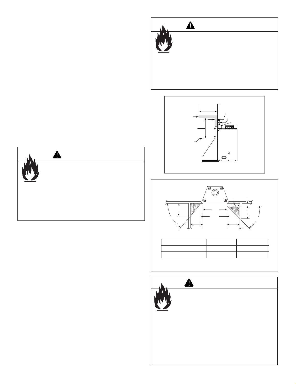
C. Mantel
A combustible mantel may be positioned no lower than
12 in. (305 mm) above the top of the replace opening. The
combustible mantel may have a maximum depth of 12 in.
(305 mm), Combustible trim pieces that project no more
than 1-1/2 in. (38 mm) from the face of the replace can
be placed no closer than 6 in. (152 mm) from the top of the
replace opening. See Figure 8.4. Combustible trim must
not cover the metal surfaces of the replace. This mantel
clearance is in accordance with Section 7-3.3.3 of ANSI/
NFPA211.
D. Sidewalls/Surrounds
Adjacent combustible side walls must be located a minimum
of 12 in. (305 mm) from the replace opening. If you are us-
ing a decorative surround constructed of combustible ma-
terial, it must be located within the shaded area dened in
Figure 8.5. Short stub walls are also acceptable if they are
contained within the shaded area.
E. Glass Doors
This replace has been tested and listed for use with doors
as specied in Section 12.B. Fireplace Components. Please
refer to the manual packed with each set of doors for instal-
lation instructions.
12 in. (305 mm)
min.
12 in. (305 mm)
max.
Top of
Fireplace
Opening
Mantel
1-1/2 in. (38 mm) max.
6 in. (152 mm) min.
Header
Standoff
Figure 8.4 Mantel Specications
Fire Risk
• Maintain clearances.
• Use only non-combustible material below
standoffs, material such as cement board is
acceptable.
WARNING
• Framing or nishing material used on the front of, or
in front of, the appliance closer than the minimums
listed, must be constructed entirely of noncombustible
materials (i.e., steel studs, concrete board, etc.).
Outdoor Lifestyles by Hearth & Home Technologies • Montana US-CAN • 4039-156 Rev R • 09/19/13
25
9
Operating Instructions
A. General Information
Fireplaces, as well as other woodburning appliances, have
been used safely for many years. It has been our experience
that most problems are caused by improper installation and
operation of the replace. Make certain that installation and
operation of the replace system is in accordance with these
instructions.
It is extremely important that the re be supervised when-
ever the replace is in use. It is also recommended that an
annual inspection be performed on the replace system to
determine if the ue system needs to be cleaned, or as in
the case of any appliance, if minor repairs are required to
maintain the system in top operating condition.
Fire Risk
• Do not operate fireplace before
reading and understanding operating
instructions.
Failure to operate replace properly may
cause re.
WARNING
Fire Risk
• For use with solid wood fuel or decorative gas
appliance only.
• Do not install unvented gas logs.
WARNING
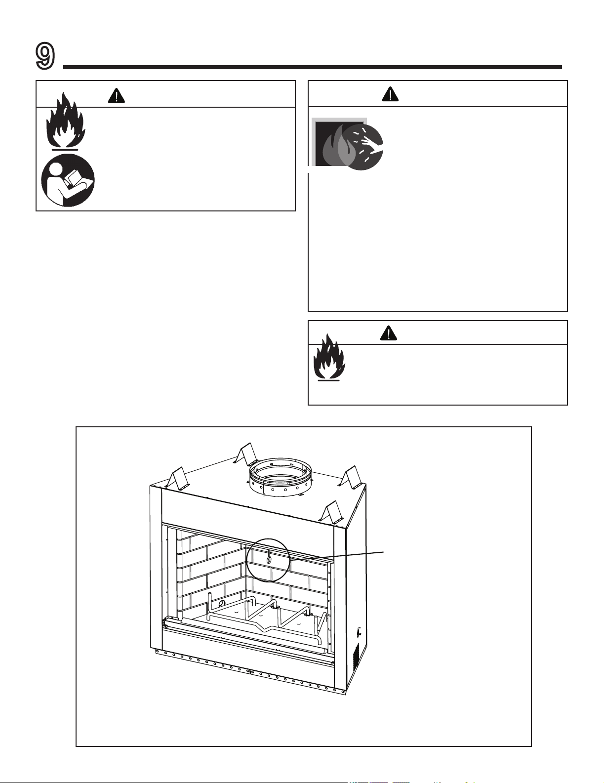
Damper
Figure 9.1 General Operating Parts
HOT SURFACES!
Glass and other surfaces are hot during
operation and cool down.
WARNING
• CAREFULLY SUPERVISE children in same room as
appliance.
• Alert children and adults to hazards of high
temperatures.
High temperatures may ignite clothing or other
ammable materials.
• Keep clothing, furniture, draperies and other combustibles
away.
Hot glass will cause burns.
• Do not touch glass until it is cooled
• NEVER allow children to touch glass
• Keep children away
►

Outdoor Lifestyles by Hearth & Home Technologies • Montana US-CAN • 4039-156 Rev R • 09/19/13
26
D. Firescreen
A rescreen is always provided to control sparks. It must be
closed whenever the replace is in use. Glass doors or re-
screens must not be used to hold burning material inside the
replace. Only those glass doors speci cally tested and list-
ed for use with the speci c replace model should be used.
Screens should be closed when the glass doors are closed
FULLY OPEN
CORRECT
PARTLY CLOSED
INCORRECT
PARTLY OPEN
INCORRECT
FULLY CLOSED
CORRECT
Figure 9.2 Proper Operating Positions of Bi-fold Doors
Fire Risk
• Close rescreen when burning replace.
• Do not use rescreen or glass doors to
hold burning material in replace.
Firescreen controls sparks.
Glass may break or burning material may
roll out.
WARNING
Fire Risk
Smoke Risk
• Doors must be fully opened or fully closed
when operating replace.
Partially opened doors may draw ame, smoke
or heat from replace.
WARNING
Asphyxiation Risk
Fire Risk
• Open damper to operate replace.
Closed damper will over- re replace and
prevent venting of combustion gases.
WARNING
B. Clear Space Near the Fireplace
Combustible materials must not be stored on the hearth ex-
tension. Room furnishings such as drapes, curtains, chairs
or other combustibles must be at least 4 ft (1.22 m) from the
open front of the replace.
C. Flue Damper
The ue damper must be in full open position, and is oper-
ated by moving the handle up toward the top of the replace.
Before lighting the re, verify this by looking up from the in-
side of the replace. Always operate this replace with the
damper fully open. Please note: Down drafts, obstructions,
damaged or poor (wet) fuels can cause smoke spillage.
See Figure 9.1 for location and operation.
E. Glass Doors
Most ef cient replace operation using glass doors is with
the doors open. When the doors are open the screen must
be closed. Only Hearth & Home Technologies glass doors
may be used. See Figure 9.2 for proper glass door opera-
tion.
F. Grate
The factory installed integral grate must be used to hold the
logs from falling out of an open replace and to allow air to
pass between the burning logs. It is important to keep the
re off the hearth and to allow the ashes to collect beneath
the re, thereby forming a layer of additional heat protection.
Fire Risk
• Use only factory installed integral grate.
May cause over re.
WARNING
Outdoor Lifestyles by Hearth & Home Technologies • Montana US-CAN • 4039-156 Rev R • 09/19/13
27
G. Wood Fuel
Firewood
Your replace performance depends on the quality of the
rewood you use. All seasoned wood, regardless of spe-
cies, contains about 8,000 BTU’s per pound, and hard-
woods have a greater density than soft woods. A piece
of hardwood will contain about 60% more BTU’s than
an equal size piece of soft wood. Firewood is commonly
sold by the cord (128 cu. ft.). A cord of seasoned oak
(hardwood) would contain about 60% more potential en-
ergy than a cord of seasoned pine (soft wood).
Examples of soft wood trees are Douglas r, pine, spruce,
and cedar, poplar, aspen and alder. Soft woods require
less time to dry, burn faster and are easier to ignite than
hardwoods.
Examples of hardwood trees are oak, maple, apple, and
birch. Hardwoods require more time to season, burn
slower and are usually harder to ignite than soft woods.
The best wood fuel is a combination of soft wood and
hardwood. Start the re with soft wood; the re will give
off quick heat to bring the replace up to operating tem-
perature, and then the hardwood can be added for slow,
even heat and longer burn time.
Moisture
Regardless of which species of wood you burn, the single
most important factor that effects the way your replace
operates is the amount of moisture in the wood. The ma-
jority of the problems replace owners experience are
caused by trying to burn wet, unseasoned wood.
Freshly cut wood can be as much water as it is wood,
having a moisture content of around 50%. Imagine a
wooden bucket that weighs about eight pounds. Fill it
with a gallon of water, put it in the replace and try to burn
it. This sounds ridiculous but that is exactly what you are
doing if you burn unseasoned wood.
Seasoning
Seasoned rewood is nothing more than wood that is
cut to size, split and air dried to a moisture content of
around 20%. The time it takes to season wood varies
from around nine months for soft woods to as long as
eighteen months for hardwoods. The key to seasoning
wood is to be sure it has been split, exposing the wet
interior and increasing the surface area of each piece. A
tree that was cut down a year ago and not split is likely
to have almost as high a moisture content now as it did
when it was cut.
The following guideline will ensure properly seasoned
wood:
• Stack the wood to allow air to circulate freely around
and through the woodpile.
• Elevate the woodpile off the ground to allow air
circulation underneath.
• The smaller the pieces, the faster the drying process.
Any piece over 6 in. (152 mm) in diameter should be
split.
• Cover the top of the woodpile for protection from
rain and snow. Avoid covering the sides and ends
completely. Doing so may trap moisture from the
ground and impede air circulation.
The problems with burning wet, unseasoned wood are
twofold: First, you will receive less heat output from wet
wood because it requires energy in the form of heat to
evaporate the water trapped inside. This is wasted ener-
gy that should be used for heating your home. Secondly,
this moisture evaporates in the form of steam which has
a cooling effect in your replace and chimney system.
When combined with tar and other organic vapors from
burning wood it will form creosote which condenses in
the relatively cool replace and chimney.
Fire Risk
• Do NOT burn wet or green wood.
• Store wood in dry location.
• Stack wood so both ends are exposed to
air.
Wet, unseasoned wood can cause
accumulation of creosote.
WARNING
Fire Risk
Do NOT store wood:
• Closer than required clearances to
combustibles to replace.
• Within space required for loading or ash
removal.
WARNING
Outdoor Lifestyles by Hearth & Home Technologies • Montana US-CAN • 4039-156 Rev R • 09/19/13
28
H. Starting a Fire
Check the ue damper to be certain it is in the full open po-
sition. Place crumpled or twisted paper under the replace
grate. Loosely arrange kindling or small pieces of wood to
form a layer above the paper.
The res must be built on the replace grate, without danger
of the burning fuel falling out of the replace opening.
Light the paper and add small pieces of wood until a hot bed
of embers has been established.
After establishing the re bed, and the small rewood is burn-
ing briskly, add a minimum of three average sized pieces of
split rewood, place the wood in such a manner to allow
combustion air and ames between them.
Note: The rst three or four res should be of moderate
size to allow the oils and binders to be burned from the
replace and the refractory and paint to cure. You may
notice an industrial odor the rst few res. This is considered
normal.
Note: When rst lighting your replace, it may be necessary
to pre-warm the ue to establish a draft. This is done by
holding a rolled up piece of burning newspaper under the
ue damper for a few moments. This will help reduce smoke
spillage during start-up.
Odors and vapors released during initial
operation.
• Curing of high temperature paint.
• Open windows for air circulation.
Odors may be irritating to sensitive individuals.
CAUTION
Fire Risk
Keep combustible materials, gasoline and
other ammable vapors and liquids clear of
replace.
• Do NOT store ammable materials close
to the replace.
• Do NOT use gasoline, lantern fuel,
kerosene, charcoal lighter uid or similar
liquids to start or “freshen up” a re in this
replace.
• Keep all such liquids well away from the
replace while it is in use.
Combustible materials may ignite.
WARNING
With outdoor applications, wind may affect the ame
pattern and performance of the replace. Smoke
spillage and sporadic ame extending beyond the
front of the replace may be possible when doors
are open.
CAUTION
►
Outdoor Lifestyles by Hearth & Home Technologies • Montana US-CAN • 4039-156 Rev R • 09/19/13
29
Diagnostics and Problem Solving
10
Troubleshooting
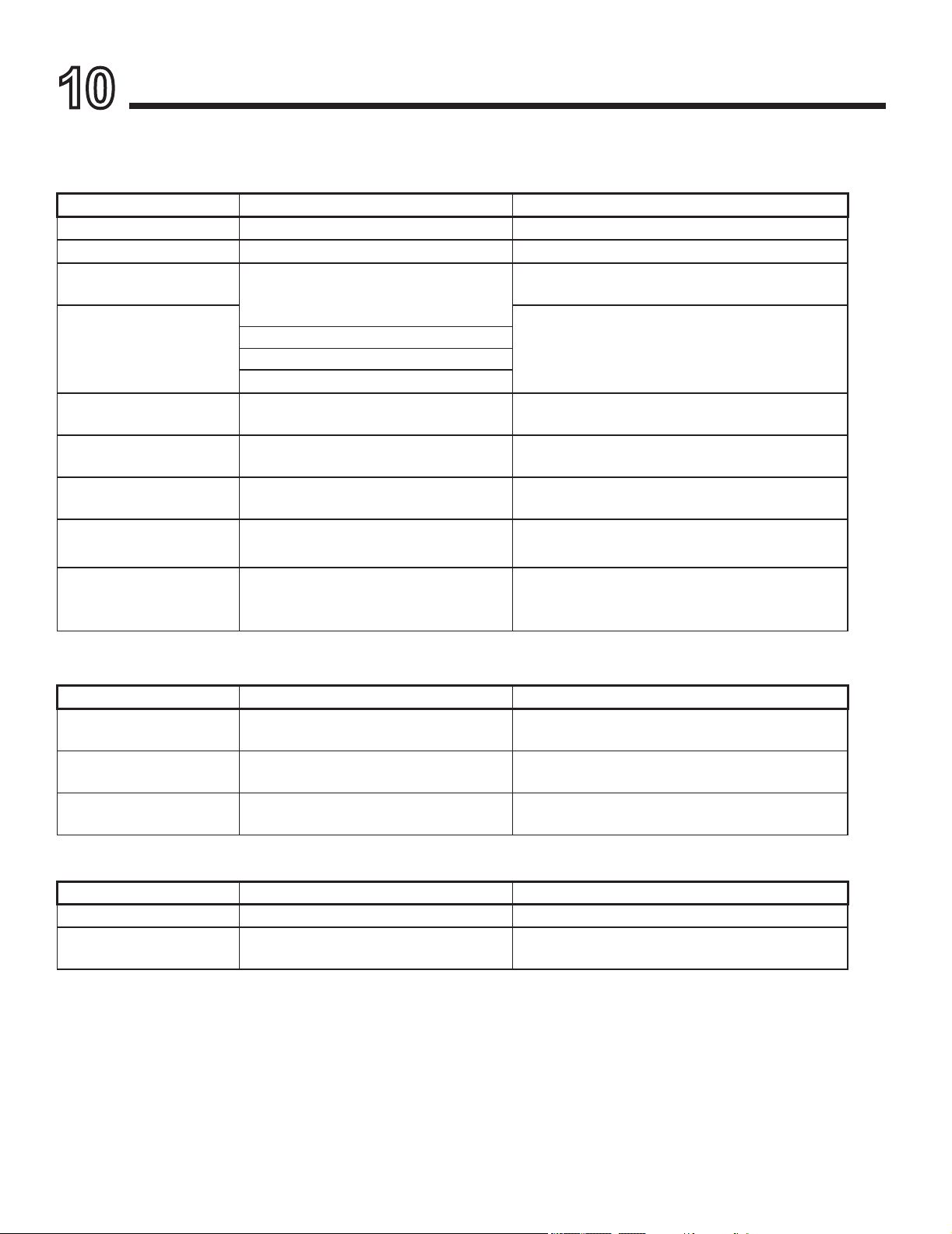
I can’t get a good re going. What am I doing wrong?
Diagnostic Questions Possible Causes of Condition Solutions
Is the damper open? • No draft Open damper.
Is there enough paper/starter? • Insufcient heat to ignite kindling Use more paper/starter.
Is there enough kindling?
Is the kindling dry?
• Insufcient heat to ignite fuel Use more dry kindling.
Is there enough or too much
wood? Is it too large? Is it dry
enough?
• Insufcient heat to establish draft Use small split wood that is well seasoned (split, covered on
top at least 6 months, preferably a year).
• Insufcient air passage
• Insufcient surface area
• Ignition temperature high due to moisture
Are there adequate air spaces
between fuel pieces?
• Insufcient combustion air and exposed
surface area
Arrange kindling and wood for air movement.
Is the chimney pre-warmed? • Exposed, cold chimney down drafting Use lighted rolled newspaper at throat or ue opening to
start upward movement.
Does the kindling, wood not
ignite?
• Condition, amount, arrangement of kindling
and fuel
Use more, drier, well-spaced kindling and fuel.
Does the kindling ignite, but the
fuel doesn’t?
• Amount of kindling Use more kindling; use smaller, dry wood.
• Condition of fuel
Does the fuel ignite, but not burn
well?
• Condition of fuel Use well-seasoned wood and sufcient amount; turn
exhaust fans off; open window slightly. Perform Simplied
House Pressure Test.
• Draft problem
I don’t get enough/any heat from the replace. What can I do about it?
Diagnostic Questions Possible Causes of Condition Solutions
How much wood is used for re? • Insufcient fuel Make larger res.
How well seasoned is the wood? • Condition of fuel Burn seasoned wood: covered on top, split and stacked for
9 months to 2 years.
How much heat output do you
expect?
• Unrealistic expectations Explanation of decorative nature of replace; suggestion of
approved replace insert.
The replace burns the wood too fast. What can I do?
Diagnostic Questions Possible Causes of Condition Solutions
Do you have glass doors? • Need to slow air intake Add glass doors.
What is the condition of the
wood?
• Extremely dry wood Mix in less seasoned wood after re established.
Outdoor Lifestyles by Hearth & Home Technologies • Montana US-CAN • 4039-156 Rev R • 09/19/13
30
A. Disposal of Ashes
Ashes should be placed in a metal container with a tight-t-
ting lid. The closed container of ashes should be placed on
a noncombustible oor or on the ground, well away from all
combustible materials, pending nal disposal. If the ashes
are disposed of by burial in soil or otherwise locally dis-
persed, they should be retained in the closed container until
all embers have thoroughly cooled.
B. Chimney Inspection/Cleaning
Inspect the chimney internally for obstructions and construc-
tion damage. Flue pipe joints and seams must be continu-
ous and mechanically tight.
The chimney should be inspected once every two months
during the heating season.
If creosote has accumulated, it should be removed to reduce
the risk of a chimney re.
Refer to Figure 11.1 to remove/reinstall termination caps.
Chimney
Remove 4 screws
and lift top pan off.
Cap
Slip
Section
ST1175/ST475
Square Termination Cap
Cap
Remove screws,
lift top cover.
Top Cover
TR11/TR11T
TR444/TR442
Round Termination Cap
TCT1175
Terra Cotta
Termination Cap
Remove 2 screws from
the front and back and
lift the top off.
Figure 11.1 Chimney & Termination Cap Cleaning
Fire Risk
Disposal of ashes
• Ashes should be placed in metal container with tight
tting lid.
• Do not place metal container on combustible
surface.
• Ashes should be retained in closed container until all
embers have thoroughly cooled.
WARNING
Fire Risk
Prevent creosote buildup
• Inspect chimney once every two months during heating
season.
• Remove creosote to reduce risk of chimney re.
• Ignited creosote is extremely HOT.
WARNING
C. Firebox Refractory Replacement
Check rebox refractory for excessive cracks or gaps. If
cracks exceed 1/4 in. (6 mm) in width the refractory should
be replaced. See Section 12 for replacement information.
Fire Risk
• Inspect replace refractory annually.
Crumbling, deteriorated refractory can allow
overheating of surrounding materials.
WARNING
Note: As you use the replace, expansion and contraction
will cause minor cracking of the refractory. This is normal,
unavoidable, and will not affect the performance of the
replace. If the cracks become large enough that the metal
behind the refractory is exposed or large pieces fall out, the
panels should be replaced.
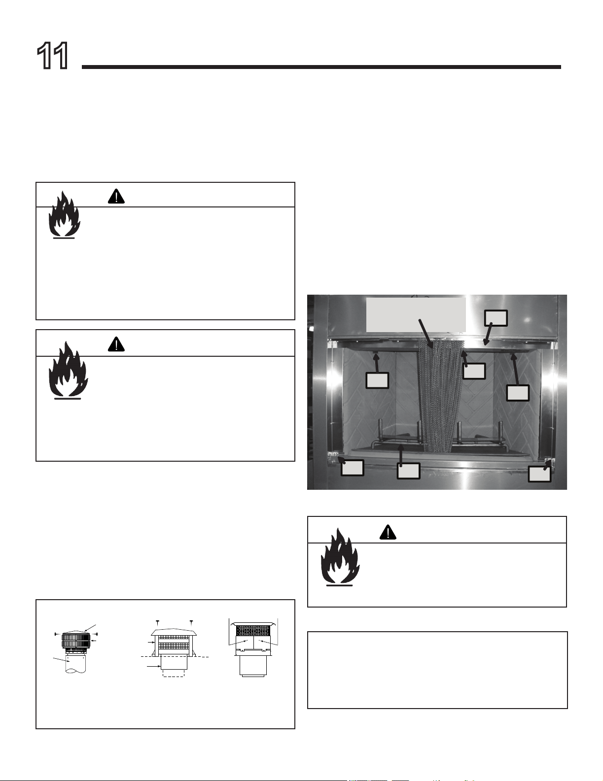
11
Maintenance and Servicing the Fireplace
1. Remove Smoke Shield, by unscrewing 8 screws.
2. Remove Hearth Retainer by unscrewing 2 screws on the
left and the right side.
3. Remove Grate Lift up and out
4. Remove side refractory, by unscrewing the 1- screw
holding the refractory bracket in place. Can start on left
or right side. Slide refratory forward and lift up and out.
Repeat on other side.
5. Remove Back Refractory, by unscrewing the one screw
holding refractory bracket in place. Lift up and out.
6. Install new refractory Reverse steps 5-1
# 1
# 2
# 3
# 4
# 4
# 5
Slide screen out of your
way as needed
# 2

Outdoor Lifestyles by Hearth & Home Technologies • Montana US-CAN • 4039-156 Rev R • 09/19/13
31
Fire Risk
• Do not use chimney cleaners or ame
colorants in your replace.
Will corrode chimney.
WARNING
D. Maintenance Task List
Asphyxiation Risk
Fire Risk
Annual inspection by qualified technician
recommended.
Check:
• Condition of doors, surrounds and fronts
• Condition of glass and glass assembly
• Obstructions of combustion and ventilation
air
• Gas connections and ttings (if present)
• Obstructions of termination cap
• Refractory panels
Clean:
• Glass
• Air passageways, grilles
WARNING
Handle glass assembly with care.
When cleaning glass door:
• Avoid striking, scratching or slamming
glass.
• Do NOT use abrasive cleaners.
• Use a hard water deposit glass cleaner on
white lm.
• Do NOT clean glass when it is hot.
CAUTION
E. Chimney Fire
In the event of a chimney re:
• Have the chimney and adjacent structure inspected by
qualied professionals. Hearth & Home Technologies
recommends that NFI or CSIA certied professionals, or
technicians under the direction of certied professionals,
conduct a minimum of an NFPA 211 Level 2 inspection
of the chimney.
• Replace components of the chimney and replace as
specied by the professionals.
• Ensure all joints are properly engaged and the chimney
is properly secured.
A chimney re can permanently damage your chimney sys-
tem. Failure to replace damaged components and make
proper repairs creates risk of re.
Inspect Maintenance Tasks
Screens 1 Assess condition of screen and replace as necessary. Screens are required.
2 Verify maintenance of proper clearance to combustible household objects.
Glass Doors 1 Inspect glass panels for cracks. Replace if this condition is present.
2 Conrm there is no damage to glass or glass frame. Replace as necessary.
3 Clean glass using a non-abrasive cleaner such as Brasso©.
Circulation Compartment 1 Remove any foreign objects.
2 Verify unobstructed air circulation.
Firebox 1 Inspect condition of refractory. Replace if crumbly, deteriorated, or if cracks exceed 1/4 in. (6
mm).
Chimney 1 Inspect for blockage or obstruction such as bird nests, leaves, etc.
2 Conrm that termination cap remains clear and unobstructed by plants, etc.
3 Verify that termination cap clearance to subsequent construction (building additions) has been
maintained.
4 Inspect for corrosion or separation.
5 Verify weather stripping, sealing and ashing remain intact.
6 Inspect for creosote and remove as needed. (See Sections 10 and 11)
Grate 1 If grate burns out, it should be replaced only with the grate specied on the rating plate and in
the replacement parts list for this replace.
Outdoor Lifestyles by Hearth & Home Technologies • Montana US-CAN • 4039-156 Rev R • 09/19/13
32
12
Reference Materials
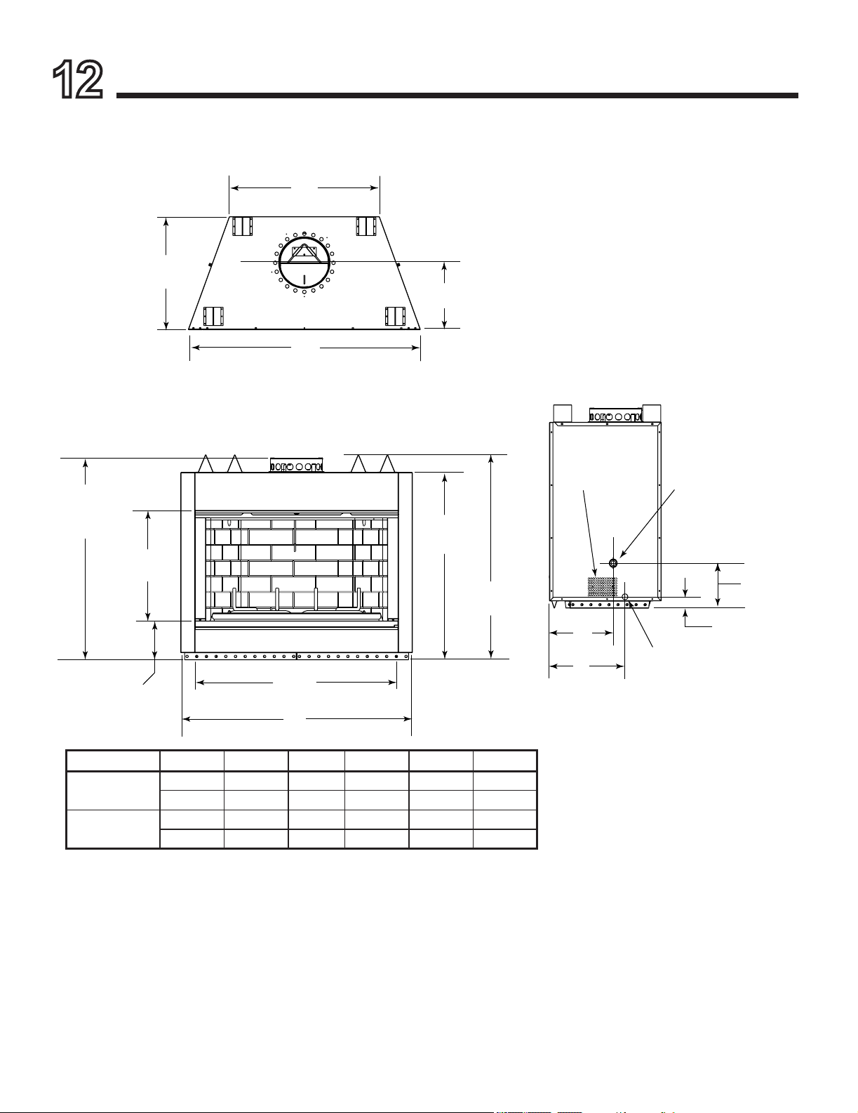
A. Fireplace Dimensions
C
23 in.
[597 mm]
D
B
9-1/2 in.
[241 mm]
E
Gas Log
Knockout
(both sides)
F
2-3/8 in.
[60 mm]
Outside Air
(both sides)
Gas Knockout for
Optional Integrated Burner
(both sides)
Model A B C D E F
MONTANA-36
36 in. 42 in. 25 in. 13-7/8 in. 13-1/4 in. 15-3/4 in.
915 mm 1067 mm 635 mm 353 mm 337 mm 400 mm
MONTANA-42
42 in. 48 in. 31 in. 14 in. 14 in. 16-3/4 in.
1067 mm 1219 mm 787 mm 356 mm 356 mm 425 mm
42-3/8 in.
[1076 mm]
38-3/4 in.
[984 mm]
A
23-1/2 in.
[597 mm]
6-3/4 in.
[171 mm]
B
41-3/4 in.
[1060 mm]
(effective height)
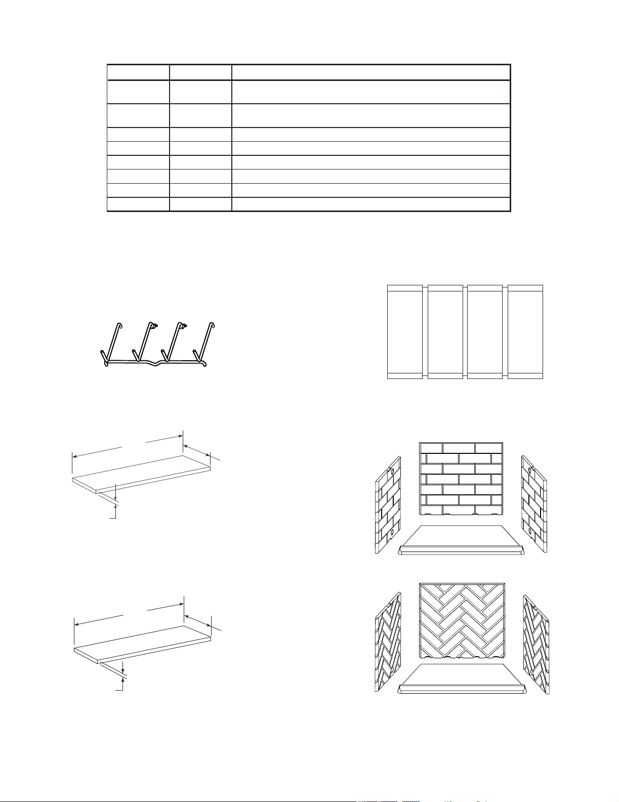
Outdoor Lifestyles by Hearth & Home Technologies • Montana US-CAN • 4039-156 Rev R • 09/19/13
33
B. Fireplace Components
Bi-fold Glass Doors
Herringbone Pattern Refractory
Traditional Brick Pattern Refractory
20 in.
(508 mm)
66 in.
(1676 mm)
1/2 in.
(13 mm)
HX4 Hearth Extension
16 in.
(406 mm)
52 in.
(1321 mm)
1/2 in.
(13 mm)
HX3 Hearth Extension
Description
MONTANA-36 MONTANA-42
Fireplace with Integral Grate, Cooling Air Kit, Traditional Brick Refractory
and Hearth Protection Strips
MONTANA-36H MONTANA-42H
Fireplace with Integral Grate, Cooling Air Kit, Herringbone Pattern
Refractory and Hearth Protection Strips
DM1836S DM1842S Bi-fold Glass Doors, Clear-View - Stainless Steel
HX3 HX4 Hearth Extension
WC42S Weather Cover - Stainless Steel
GR33 GR21 Integral Grate (included with replace)
Building Set Enclosure
OGL-42 Outdoor Gas Log (natural or propane gas)
GR21 & GR33
Integral Grate

Outdoor Lifestyles by Hearth & Home Technologies • Montana US-CAN • 4039-156 Rev R • 09/19/13
34
C. Chimney Components
The following pictures show only those chimney components which may be safely used with this replace.
13 in.
(330 mm)
14 in.
(356 mm)
14 in.
(356 mm)
5-1/4 in.
(133 mm)
4 in. (102 mm)
CAK5A Chimney Air Kit
ID4 Insulated Duct
UD4 Uninsulated Duct
42 in.
(1067 mm)
4 in. (102 mm) i.d.
42 in.
(1067 mm)
4 in. (102 mm) i.d.
A
11 in.
(279 mm)
13 in.
(330 mm)
B
Chimney Sections
A = Actual Length
B = Effective Length (length of
chimney part after it has
been snapped to another)
SL11/SL4 Chimney Stabilizer
Outside Diameter
13 in./330 mm
Inside
Diameter
11 in./279 mm SL11
10 in./254 mm SL4
20-3/4 in.
527 mm
Catalog # A B
US CAN in mm in mm
SL1106 SL406 6 152 4-3/4 121
SL1112 SL412 12 305 10-3/4 273
SL1118 SL418 18 457 16-3/4 425
SL1136 SL436 36 914 34-3/4 883
SL1148 SL448 48 1219 46-3/4 1187
18 in.
(457 mm)
SLA10 Adapter
Catalog #
DescriptionUS CAN
CAK5A CAK5A Chimney Air Kit
n/a SLA10 Adapter 11 in. (457mm) long
ID4 ID4 Insulated Duct/Outside Air
UD4 UD4 Uninsulated Duct/Outside Air
SL1106 SL406 Chimney Section - 6 in. (152 mm) long
SL1112 SL412 Chimney Section - 12 in. (305 mm) long
SL1118 SL418 Chimney Section - 18 in. (457 mm) long
SL1136 SL436 Chimney Section - 36 in. (914 mm) long
SL1148 SL448 Chimney Section - 48 in. (1219 mm) long
SL11 SL4 Chimney Stabilizer
SL1130 SL430 Chimney Offset/Return - 30 deg
FS538 FS538 Ceiling Firestop - Straight
FS540 FS540 Ceiling Firestop - 30 deg
AS10 AS10 Straight Attic Insulation Shield, 24 in. (610 mm)
JB577 JB577 Chimney Joint Band
CB576 CB576 Chimney Bracket
RF570 RF570 Roof Flashing - Flat to 6/12 Pitch
RF571 RF571 Roof Flashing - 6/12 to 12/12 Pitch
TR11 TR444 Round Termination Cap
TR11T TR442 Round Telescoping Termination Cap
TCT1175 Terra Cotta Termination Cap
ST1175 ST475 Square Termination Cap
DTO134 DTO134 Short Octagon Decorative Cap
DTO146 DTO146 Tall Octagon Decorative Cap
DTS134 DTS146 Short Square Decorative Cap
DTS146 DTS146 Tall Square Decorative Cap
CT56 CT56 Chase Top
LDS33 LDS33 Decorative Shroud - 3 ft x 3 ft (.91 m x .91 m)
LDS46 LDS46 Decorative Shroud - 4 ft x 6 ft (1.22 m x 1.83 m)
LDS-BV LDS-BV
Decorative Shroud - 26 in. x 26 in.
(660 mm x 660 mm)
Field Constructed Shrouds (See “Woodburning
Termination Cap”)
CT-11A n/a Adapter-May be used with the following Copper Caps
n/a CT-Series
na DT-Series
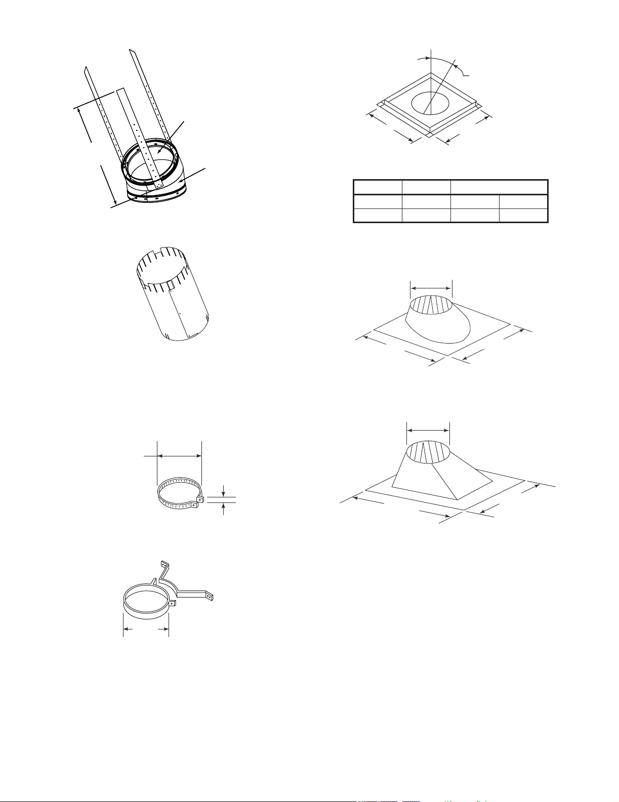
Outdoor Lifestyles by Hearth & Home Technologies • Montana US-CAN • 4039-156 Rev R • 09/19/13
35
A
B
17 in. (432 mm)
Ceiling Firestop
Assembled
Diameter: 17 in./432 mm
Height: 24 in./610 mm
AS10 Straight Attic Insulation Shield
2 in.
(51 mm)
13 in.
(330 mm)
JB577 Chimney Joint Band
13 in.
(330 mm)
CB576 Chimney Joint Band
39-7/8 in.
(1013 mm)
28 in.
(711 mm)
15-1/4in.
(387 mm)
RF571 Roof Flashing
25-1/4 in.
(641 mm)
29 in.
(737 mm)
15-1/4 in.
(387 mm)
RF570 Roof Flashing
SL1130/SL430 Offset/Return
21 in.
533 mm
Inside
Diameter
11 in./279 mm SL11
10 in./254mm SL4
Outside
Diameter
13 in./330 mm
Catalog # A B
FS538 0-deg. 17 in. 432 mm
FS540 30-deg. 26 in. 660 mm
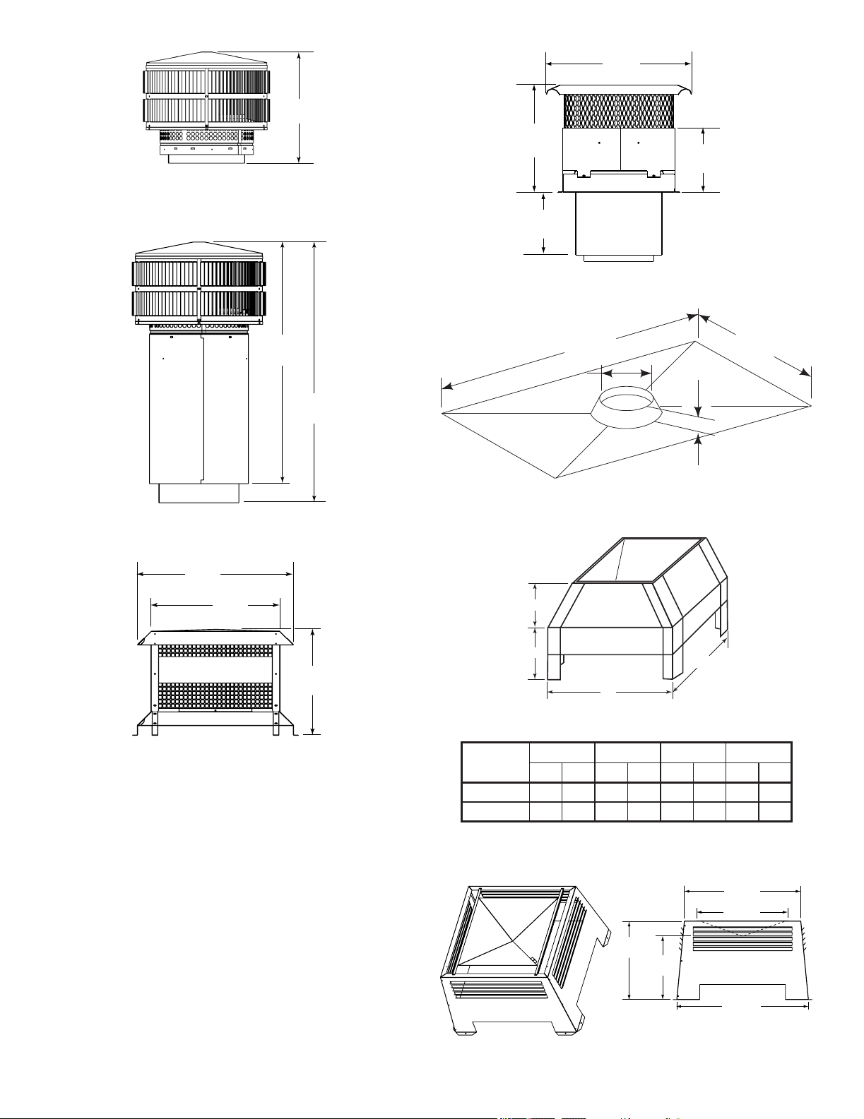
Outdoor Lifestyles by Hearth & Home Technologies • Montana US-CAN • 4039-156 Rev R • 09/19/13
36
72 in.
(1829 mm)
36 in.
(914 mm)
2 in.
(51 mm)
13-3/8 in.
(340 mm)
CT56 Chase Top
A
B
C
D
LDS33/LDS46 Decorative Shroud
TR11/TR444 Round Termination Cap
15-3/4 in.
(400 mm)
TR11T/TR442 Round Telescoping Termination Cap
32-3/8 in.
(822 mm)
34-3/8 in.
(873 mm)
ST1175/ST475 Square Termination Cap
23 in.
(584 mm)
19 in.
(483 mm)
15-5/8 in.
(397 mm)
TCT1175 Terra Cotta Cap
(available US only)
9-3/8 in.
(238 mm)
10-1/4 in.
(260 mm)
17 in.
(432 mm)
20 in.
(508 mm)
LDS-BV Decorative Shroud
23 in.
(584 mm)
22 in.
(533 mm)
26 in.
(660 mm)
15-1/2 in.
(394 mm)
12-1/2 in.
(318 mm)
Catalog #
A B C D
in. mm in. mm in. mm in. mm
LDS33 36 914 36 914 8.5 216 11 279
LDS46 48 1219 72 1829 8.5 216 11 279
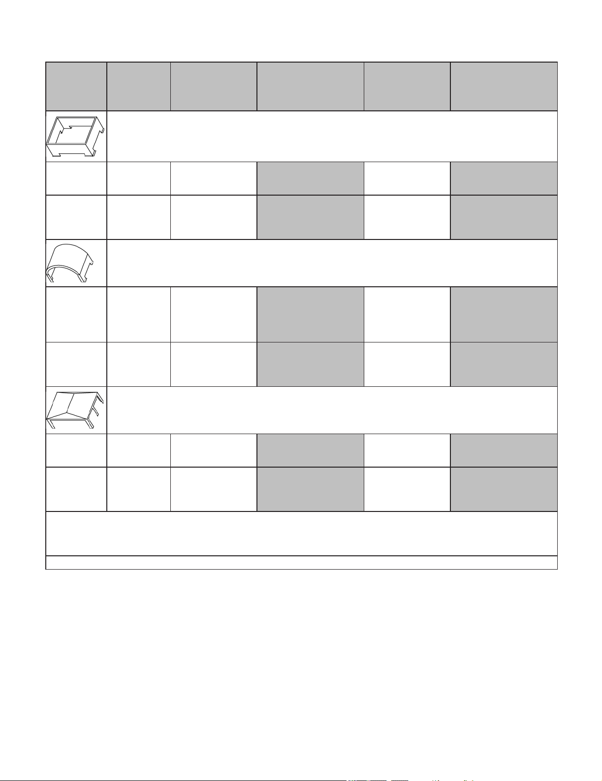
Outdoor Lifestyles by Hearth & Home Technologies • Montana US-CAN • 4039-156 Rev R • 09/19/13
37
Woodburning Termination Cap
Shroud
TS345/T445
(Top Vent)
TR342/TR344
TR442/TR444
TV342
TR342/TR344*
TR442/TR444*
(* with TR-TVK installed)
TR11/TR11T
TV11/TV11T
TR11/TR11T*
(* with TR-TVK installed)
OPEN TOP with solid sides and 3 in. (76 mm) opening at the bottom
Mnimum Base
Dimensions
23 in. x 23 in.
(584 x 584 mm)
28 x 28 in.
(711 x 711 mm)
with Radiation Shield
26 x 26 in.
(660 x 660 mm)
32 x 32 in.
(813 x 813 mm)
with Radiation Shield
26 x 26 in.
(660 x 660 mm)
Minimum Top
Dimensions
20 x 20 in.
(508 x 508 mm)
25 x 25 in.
(635 x 635 mm)
23 x 23 in.
(584 x 584 mm)
29 x 29 in.
(737 x 737 mm)
23 x 23 in.
(584 x 584 mm)
MAILBOX STYLE with open ends and 3 in. (76 mm) opening at the bottom of the sides.
Minimum Base
Dimensions
N/A
26.5 x 28 in.
(673 x 711 mm)
with Radiation Shield
28 x 30 in.
(711 x 762 mm)
34 x 34 in.
(864 x 864 mm)
with Radiation Shield
28 x 30 in.
(711 x 762 mm)
with Radiation Shield or
34 x 34 in.
(864 x 864 mm)
Minimum Height N/A
28 1/4 in.
(718 mm)
27 1/2 in.
(699 mm)
28 1/4 in.
(718 mm)
27 1/2 in.
(699 mm)
ROOFED STYLE with 12 x 22 in. (264 sq. in.) (305 x 559 mm) opening on each side and 3 in. (76 mm) space between the
radiation shield and chase top.
Minimum Base
Dimensions
N/A
27 x 27 in.
(686 x 686 mm)
with Radiation Shield
27 x 27 in.
(686 x 686 mm)
with Radiation Shield
34 x 34 in.
(864 x 864 mm)
with Radiation Shield
34 x 34 in.
(864 x 864 mm)
with Radiation Shield
Minimum Height N/A
23 in.
(584 mm)
23 in.
(584 mm)
23 in.
(584 mm)
23 in.
(584 mm)
Minimum Height is measured from the bottom of the termination cap:
Minimum height is established with the bottom of the termination cap 7 in. (178 mm) above the chase top. Minimum height must increase
accordingly for any height above 7 in. (178 mm).
All dimensions are INSIDE dimensions.
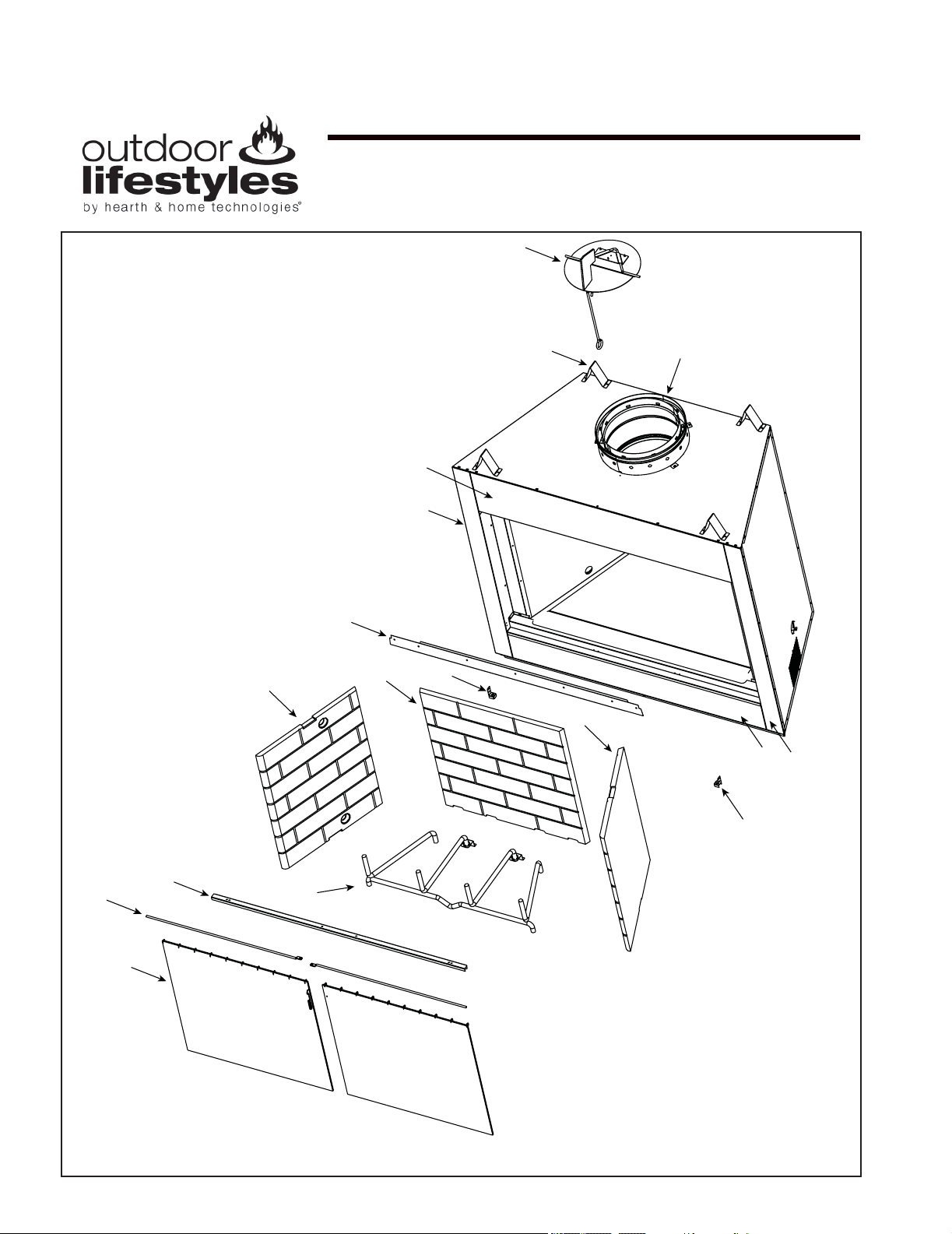
Outdoor Lifestyles by Hearth & Home Technologies • Montana US-CAN • 4039-156 Rev R • 09/19/13
38
D. Service Parts
Service Parts
MONTANA-36, MONTANA-36H
Beginning Manufacturing Date: Sept 2003
Ending Manufacturing Date: Active
36” Outdoor Woodburning Fireplace
2
1
3
4
5
6
8
9
10
11
12
13
14
15
16
17
7
Part number list on following page.
10/12
►
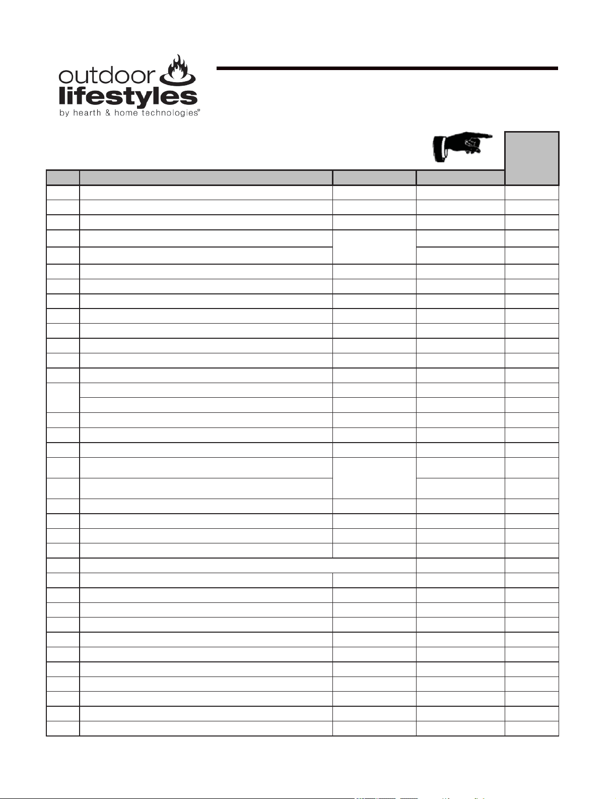
Outdoor Lifestyles by Hearth & Home Technologies • Montana US-CAN • 4039-156 Rev R • 09/19/13
39
Service Parts
MONTANA-36, MONTANA-36H
Beginning Manufacturing Date: Sept 2003
Ending Manufacturing Date: Active
IMPORTANT: THIS IS DATED INFORMATION. When requesting service or replacement
parts for your appliance please provide model number and serial number. All parts listed
in this manual may be ordered from an authorized dealer.
Stocked
in Depot
ITEM DESCRIPTION COMMENTS PART NUMBER
1 Starter Collar 30399
2 Damper Assembly 34454
3 Top Stand Off
Qty 4 Req
4044-111
4 Upper Front Face
Not replaceable
must order overlay
4004-107
4039-114
5 Side Column Left 30375
6 Top Door Track 4039-118
7 Door Clips
Qty 2 Req
30407
Traditional Refractory
8
Right Side Refractory
28393
9
Back Refractory
29992
10
Left Side Refractory
28393
Hearth Refractory
29993
11 Grate GR33 Y
12
Hearth Pan
Pre AK560843
4039-102
Hearth Stone Retainer
Post Ak560843
4039-108
13 Firescreen Rod
Qry 2 Req
4039-120
14 Screen Assembly
Qty 2 Req
4039-119
15 Door Pivet Clip
Qty 2 Req
31527
16 Bottom Front Face
Not replaceable
must order overlay
4004-107
4039-113
17 Side column Right 30376
Gas Tube 4039-116
Smoke Shield 4039-106
Herringbone refractory available post week 3/04
8
Right Side Refractory
4010-013
9
Back Refractory
4010-016
10
Left Side Refractory
4010-014
Hearth Refractory
4010-019

Outdoor Lifestyles by Hearth & Home Technologies • Montana US-CAN • 4039-156 Rev R • 09/19/13
40
Service Parts
MONTANA-42, MONTANA-42H
Beginning Manufacturing Date: Sept 2003
Ending Manufacturing Date: Active
42” Outdoor Woodburning Fireplace
2
1
3
4
5
6
8
9
10
11
12
13
14
15
16
17
7
Part number list on following page.
10/12
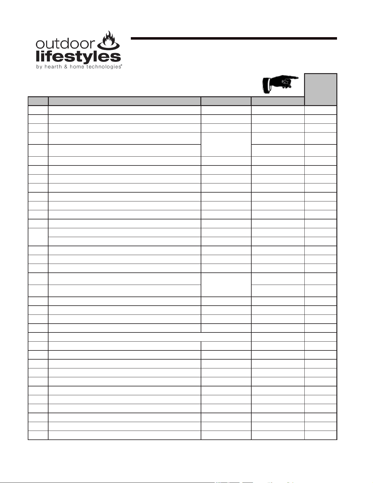
Outdoor Lifestyles by Hearth & Home Technologies • Montana US-CAN • 4039-156 Rev R • 09/19/13
41
Service Parts
MONTANA-42, MONTANA-42H
Beginning Manufacturing Date: Sept 2003
Ending Manufacturing Date: Active
IMPORTANT: THIS IS DATED INFORMATION. When requesting service or replacement
parts for your appliance please provide model number and serial number. All parts listed
in this manual may be ordered from an authorized dealer.
Stocked
in Depot
ITEM DESCRIPTION COMMENTS PART NUMBER
1
Starter Collar 30399
2 Damper Assembly 34454
3 Top Stand Off
Qty 4 Req
4044-111
4 Upper Front Face
Not replaceable
must order overlay
4004-107
30395
5 Side Column Left 30375
6 Top Door Track 30400
7 Door Clips Qty 2 Req 30407
Tradtional Refractory
8
Right Side Refractory
28393
9
Back Refractory
28394
10
Left Side Refractory
28393
Hearth Refractory
28391
11 Grate GR21 Y
12
Hearth Pan Pre AK560843 30405
Hearth Stone Retainer Post AK560843 30403
13 Firescreen Rod Qry 2 Req 31375 Y
14 Screen Assembly Qty 2 Req 30371
15 Door Pivet Clip Qty 2 Req 31527
16 Bottom Front Face
Not replaceable
must order overlay
4004-107
30393
17 Side column Right 30376
Gas Tube 30412
Smoke Shield 30402
Herringbone refractory available post week 3/04
8
Right Side Refractory
4010-013
9
Back Refractory
4010-015
10
Left Side Refractory
4010-014
Hearth Refractory
4010-020

Outdoor Lifestyles by Hearth & Home Technologies • Montana US-CAN • 4039-156 Rev R • 09/19/13
42
E. Limited Warranty
Outdoor Lifestyles by Hearth & Home Technologies™
Limited Warranty
Hearth & Home Technologies (“HHT”) extends the following warranty for all Outdoor Lifestyles by HHT™
brand products (“Products”) that are purchased from an HHT authorized dealer.
WARRANTY COVERAGE:
HHT warrants to the original owner of the Product at the site of installation, and to any transferee taking
ownership of the Product at the site of installation within one year following the date of original purchase,
that the Product will be free from defects in materials and workmanship at the time of manufacture. After
installation, if covered components manufactured by HHT are found to be defective in materials or
workmanship during the applicable warranty period, HHT will, at its option, repair or replace the covered
components. This warranty is subject to conditions, exclusions and limitations as described below.
WARRANTY PERIOD:
The warranty period runs for one year, beginning on the earlier of: (i) the date of invoice for the Product;
(ii) in the case of new home construction, the date of first occupancy of the residence or six months after
the date of sale of the Product by an HHT authorized dealer, whichever occurs first; or (iii) the date 24
months following the date of Product shipment from HHT, regardless of the invoice or occupancy date.
WARRANTY CONDITIONS:
• This warranty only covers Products that are purchased through an HHT authorized dealer or
distributor. A list of HHT authorized dealers is available on the HHT branded websites.
• This warranty is only valid while the Product remains at the site of original installation.
• Contact your installing dealer for warranty service. If the installing dealer is unable to provide
necessary parts, contact the nearest HHT authorized dealer or supplier. Additional service fees
may apply if you are seeking warranty service from a dealer other than the dealer from whom
you originally purchased the Product.
• Check with your dealer in advance for any costs to you when arranging a warranty call. Travel
and shipping charges for parts are not covered by this warranty.
WARRANTY EXCLUSIONS:
This warranty does not cover the following:
• Changes in surface finishes as a result of normal use. As a heating appliance, some changes in
color of interior and exterior surface finishes may occur; this is not a flaw and not covered under
warranty.
• Damage to printed, plated, or enameled surfaces caused by fingerprints, accidents, misuse,
scratches, melted items, or other external sources and residues left on surfaces from the use of
abrasive cleaners or polishes.
• Repair or replacement of parts that are subject to normal wear and tear during the warranty
period. These parts include: paint, firebricks, grates, flame guides and the discoloration of glass.
• Minor expansion, contraction, or movement of certain parts causing noise. These conditions are
normal and complaints related to this noise are not covered by this warranty.
Outdoor Lifestyles Warranty - 2108-975B - 2/15/13 - page 1
►

Outdoor Lifestyles by Hearth & Home Technologies • Montana US-CAN • 4039-156 Rev R • 09/19/13
43
Limited Warranty (continued)
• Damages resulting from: (1) failure to install, operate, or maintain the Product in accordance with
the installation instructions, operating instructions, and listing agent identification label furnished
with the Product; (2) failure to install the Product in accordance with local building codes; (3)
shipping or improper handling; (4) improper operation, abuse, misuse, continued operation with
damaged, corroded or failed components, accident, or incorrectly performed repairs; (5) inad-
equate ventilation, negative pressure or environmental conditions, including, without limitation:
hail, snow, ice, fallen branches, flooding, water damage and fading of color; (6) use of fuels other
than those specified in the operating instructions; (7) installation or use of components not
supplied with the Product or any other components not expressly authorized and approved by
HHT; (8) modification of the Product not expressly authorized and approved by HHT in writing;
and/or (9) interruptions or fluctuations of electrical power supply to the Product.
• Non-HHT venting components, hearth components or other accessories used in conjunction with
the Product.
• Any part of a pre-existing fireplace system in which an insert or a decorative gas appliance is
installed.
• The Product’s capability to heat the desired space. Information is provided to assist the consumer
and the dealer in selecting the proper appliance for the application. Consideration must be given
to the Product’s location and configuration and environmental conditions.
This warranty is void if:
• The Product has been over-fired or operated in atmospheres contaminated by chlorine, fluorine,
or other damaging chemicals. Over-firing can be identified by, but not limited to, warped plates or
tubes, rust colored cast iron, bubbling, cracking and discoloration of steel or enamel finishes and
cracking or spalling of refractory or cementitious materials.
• The Product is subjected to prolonged periods of dampness, condensation, ice or snow.
• There is any damage to the Product or other components due to water or weather damage which
is the result of, but not limited to, improper chimney or venting installation.
LIMITATIONS OF LIABILITY:
Repair or replacement in accordance with the provisions of this warranty will be the owner’s exclusive
remedy for and will constitute HHT’s sole obligation under this warranty, under any other warranty
(express or implied), or in contract, tort or otherwise; provided, however, that if HHT is unable to provide
repair or replacement in an expedient and cost effective manner, HHT may discharge all such obligations
by refunding the purchase price of the Product. No employee, agent, dealer, or other person is authorized
to give any warranty on behalf of HHT. TO THE EXTENT ALLOWED BY LAW, HHT MAKES NO OTHER
WARRANTY, EXPRESS OR IMPLIED, INCLUDING ANY WARRANTY OF MERCHANTABILITY OR
FITNESS FOR A PARTICULAR PURPOSE. HHT WILL NOT BE LIABLE FOR ANY CONSEQUENTIAL
OR INCIDENTAL DAMAGES ARISING OUT OF DEFECTS IN OR USE OF THE PRODUCTS. Some
states do not allow exclusions or limitation of incidental or consequential damages, so these limitations
may not apply to you. This warranty gives you specific rights; you also may have other rights, which vary
from state to state. The duration of any implied warranty is limited to the duration of the warranty period
specified herein.
Outdoor Lifestyles Warranty - 2108-975B - 2/15/13 - page 2
Outdoor Lifestyles by Hearth & Home Technologies • Montana US-CAN • 4039-156 Rev R • 09/19/13
44
– NOTES –
F. Contact Information
DO NOT DISCARD THIS MANUAL
CAUTION
• Important operating
and maintenance
instructions included.
• Leave this manual with
party responsible for
use and operation.
• Read, understand
and follow these
instructions for safe
installation and
operation.
DO NOT
DISCARD
This product may be covered by one or more of the following patents: (United States) 4593510, 4686807, 4766876,
4793322, 4811534, 5000162, 5016609, 5076254, 5113843, 5191877, 5218953, 5263471, 5328356, 5341794, 5347983,
5429495, 5452708, 5542407, 5601073, 5613487, 5647340, 5688568, 5762062, 5775408, 5890485, 5931661, 5941237,
5947112, 5996575, 6006743, 6019099, 6048195, 6053165, 6145502, 6170481, 6237588, 6296474, 6374822, 6413079,
6439226, 6484712, 6543698, 6550687, 6601579, 6672860, 6688302B2, 6715724B2, 6729551, 6736133, 6748940,
6748942, 6769426, 6774802, 6796302, 6840261, 6848441, 6863064, 6866205, 6869278, 6875012, 6880275, 6908039,
6919884, D320652, D445174, D462436; (Canada) 1297749, 2195264, 2225408, 2313972; (Australia) 780250, 780403,
1418504 or other U.S. and foreign patents pending.
Please contact your Outdoor Lifestyles dealer with any questions or concerns.
For the number of your nearest Outdoor Lifestyles dealer, please visit www.hearthnhome.com.
Hearth & Home Technologies
7571 215th Street West
Lakeville, MN 55044
www.hearthnhome.com