Loading ...
Loading ...
Loading ...
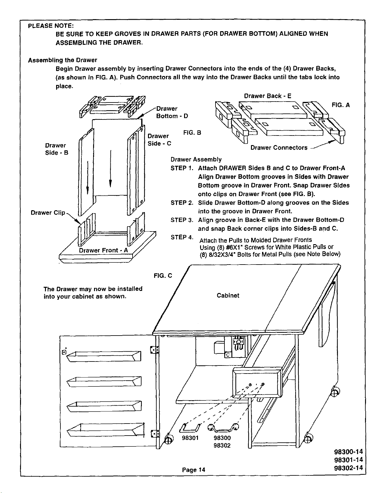
PLEASE NOTE:
BE SURE TO KEEP GROVES IN DRAWER PARTS (FOR DRAWER BOTTOM) ALIGNED WHEN
ASSEMBLING THE DRAWER.
Assembling the Drawer
Begin Drawer assembly by inserting Drawer Connectors into the ends of the (4) Drawer Backs,
(as shown in FIG. A). Push Connectors all the way into the Drawer Backs until the tabs lock into
place.
Drawer
Side - B
Drawer Cli
F/_/_o ,=_ Drawer Back - E
J_ /Drawer _--_,,_ _ FIG. A
°o.omo
Jl DrawerF, .B .
II ] II I Side-C _ _u
II I II I Drawer Connectors _'_
II I I I II I Drawer Assembly
[I I I I II I STEP1. Attach DRAWER Sides B and C to Drawer Front-A
I I I I I_ II J Align Drawer Bottom grooves in Sides with Drawer
Illl ' Ill Bottom groove in Drawer Front. Snap Drawer Sides
I( ' _-_'_l ( onto clips on Drawer Front (see FIG. B).
II /I) [I.! STEP2. Slide Drawer Bottom-D along grooves on the Sides
L_'A1 ELY.)1 into the groove in Drawer Front,
_._ll )_( STEP 3. Align groove in Back-E with the Drawer Bottom-D
N II_J_====_. _/L-_ and snap Back c°rner clips int° Sides'B and C"
LjF/// STEP 4. Attach the Pulls to Molded Drawer Fronts
Drawer Front - A_// Using (8) #6Xl Screws for White Plastic Pulis or
(8) 8132X314"Boltsfor Metal Pulls (see Note Below)
The Drawer may now be installed
into your cabinet as shown.
I
v_
•_ f t"/
/ 7 t/I/ (
/ I ._ "_/ /
f _" p. •
98301 98300 I_
98302 LF
Page 14
Cabinet / _
98300-1_
98301-14
98302-14
Loading ...
Loading ...
Loading ...