Loading ...
Loading ...
Loading ...
10
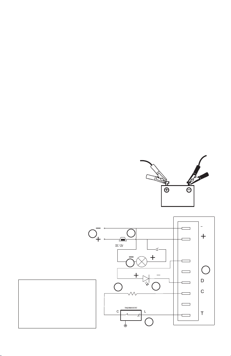
ELECTRICAL DIAGRAM
THIS FRIDGE MUST NEVER BE CONNECTED DIRECTLY
TO ANY AC (alternating current) POWER SOURCE!
THE FRIDGE MUST ONLY BE CONNECTED TO A 12V OR 24V DC
POWER SOURCE, SUCH AS A SOLAR
BATTERY SYSTEM OR CHARGE CONTROLLER.
THE FRIDGE WILL AUTOMATICALLY OPERATE ON EITHER 12V OR 24V DC.
THE USER DOES NOT NEED TO MAKE ANY ADJUSTMENT.
ATTENTION: Polarity is important in wiring this DC appliance. Be
sure that the positive terminal of the battery or charge controller
coincides with the positive wire to the compressor, and the nega-
tive terminal of the battery or charge controller coincides with the
negative wire to the compressor. The leads should be connected
using cable shoes and screwed connections. Joined leads should be
avoided.
DC POWER CONNECTION
UGP-260L1 Wiring Diagram
UGP-260L1 Schéma de Câblage
UGP-260L1 Wiring Diagram Label
1: Input power 12VDC /24VDC
2: Fuse 15 A
3: Main PCBA cooling unit
4: Interior light
5: Thermostat
6: LED Error light
7: R1(Speed selection)
1: La puissance d’entrée
12VDC/24VDC
2: Fusible 15A
3: Unité principale de refroid-
issement PCBA
4: Lumiére d’intérieur
5: Thermostat
6: LED (lumiére error)
7: R1 (sélection de vitesse)
WHITE
RED
BROWN
BLACK
YE/GN
P
F+
R E S I S TA N C E
LED errors Light/lumiere errors
Interior Light
1
2
3
5
6
7
BLANC
ROUGE
RED
ROUGE
MARRON
NOIR
BLACK
NOIR
BLACK
NOIR
BLACK
NOIR
BLACK
NOIR
Lumiere Interior
4
JAUNE/VERT
FUSE
FUSIBLE
BLACK
NOIR
RED
ROUGE
6”
4”
+ to + and - to -
positive to positive / negative to
negative (red wire) / (black wire)
12V
RED BLACK
Loading ...
Loading ...
Loading ...