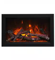
INSTALLATION AND OPERATION INSTRUCTIONS FOR
50-TRU-VIEW -XL
60-TRU-VIEW -XL
72-TRU-VIEW -XL
SAFETY INFORM ATION
WARNING
If the information in these instructions are
not followed exactly, a fire or explosion
may result causing property damage,
personal injury or loss of life.
Do not store or use gasoline or other flammable vapors
and liquids in the vicinit y of this or any other appliance.
INSTALLER: LEAVE THIS M ANUAL WITH THE APPLIANCE.
CONSUM ER: RETAIN THIS M ANUAL FOR FUTURE REFERENCE.
40-TRU-VIEW -XL

2
IMPORTANT INSTRUCTIONS....................................................................................................................................3
UNPACKING AND TESTING APPLIANCE...............................................................................................................5
GROUNDING APPLIANCE.........................................................................................................................................5
LOCATING THE FIREPLACE.....................................................................................................................................5
50-TRU-VIEW-XL.........................................................................................................................................................7
60-TRU-VIEW-XL.........................................................................................................................................................8
72 –TRU-VIEW-XL.......................................................................................................................................................9
SAFETY DRILL SCREW AREA................................................................................................................................10
HARD- WIRE INSTALLATION.................................................................................................................................10
MEDIA OPTIONS.......................................................................................................................................................19
OPERATION................................................................................................................................................................21
INSTALLING WALL THERMOSTAT........................................................................................................................23
REPLACEMENT PARTS............................................................................................................................................24
EXPLODED VIEW......................................................................................................................................................25
TROUBLE SHOOTING..............................................................................................................................................27
SERVICE HISTORY....................................................................................................................................................28
WARRANTY...............................................................................................................................................................29
INSTALLATION...........................................................................................................................................................13
FOR BATHROOM USE ..............................................................................................................................................11
MEDIA OPERATION..................................................................................................................................................20
REMOTE CONTROL OPERATION .......................................................................................................................... .22
WIRING DIAGRAM ..................................................................................................................................................26
TABLE OF CONTENTS
Please read and carefully follow all of the instruction found in this manual. Please pay special
attent ion to the safety inst ructions provided in this manual. The instructions included here will assure
that you have many years of dependable and enjoyable service from your Amantii product.
OUTDOOR INSTALLATIONS ...................................................................................................................................12
40-TRU-VIEW-XL.........................................................................................................................................................6

IM PORTANT INSTRUCTIONS
1. Read all instructions before inst alling or using this heat er.
2. Keep combustible mat erials, such as furniture, pillows, bedding, papers, clothes and curt ains at
least 3 feet from the front of the heat er; keep them away from sides and rear as well.
3. Alw ays unplug heater when it ’s not in use.
4. Do not operate the fireplace if it has a damaged cord or plug, aft er it has malfunctioned, or if the
unit has been dropped or damaged in any way.
5. Never place the heater where it may fall into a bathtub or other water cont ainers.
6. Do not run the cord under carpeting. Do not cover the cord wit h throw rugs, runners or anyt hing
else. Arrange the cord away from traffic areas where it could not be tripped over.
7. To disconnect the heat er, turn the cont rols to "OFF" before removing the plug from the out let .
8. Do not insert or allow foreign objects to enter any ventilat ion or exhaust opening, as this may
cause an electric shock, fire or damage to the heater.
9. To prevent a possible fire, do not block air int akes in any manner.
10. A heat er has hot and arcing or sparking parts inside. Do not use it in areas where gasoline, paint
or flammable liquids are used or stored.
11. Use this heater only as described in this manual. Any ot her use not recommended by the
manufacturer may cause fire, electric shock or injury to persons.
12. Avoid the use of an ext ension cord because the ext ension cord may overheat and cause a fire.
13. Always use properly grounded fused and polarized outlet s.
14. Always use ground fault protection where it is required by electrical codes.
15. Always disconnect the power before performing any cleaning, maintenance or relocation of the
heat er.
16. To prevent a possible fire, do not burn wood or ot her materials in this heat er.
17. To prevent electric shock or fire, always use a cert ified electrician, should new circuits or
outlet s be required.
18. When transporting or storing the heat er, keep it in a dry place, free from excessive vibration.
1. This appliance should not be modified under any circumstances.
2. Packaging material should be kept away from children and be disposed of in a safe manner.
Plastic bags are not toys and should be kept away from children and infants.
3. Do not use this heater in small rooms when they are occupied by persons not capable of leaving
the room on their own, unless constant supervision is provided.
4. If the glass is damaged, do not use the heater in order to avoid a hazard.
5. Children of less than 3 years should be kept away from unless continuously supervised.
6. CAUTION Some parts of this product can become very hot and cause burns. Particular attention
has to be given where children and vulnerable people are present.
3

Cautions
Do’s
·Always install the heater in accordance with this guide. If in
doubt obtain expert advice.
·Always make sure the electrical socket is accessible and located
adjacent to, but not above the heater.
·Always disconnect the heater from the electrical supply before
moving it, or carrying out cleaning, maintenance.
·Always make sure the heater is firmly secured to prevent it from
being tipped over.
·Always use a fireguard when young children and infirm persons
can come into contact with the heater.
Don’ts
·Never leave children unsupervised in a room where the heater is
ON and unguarded.
·Never obstruct or cover the fan outlet or force items into heater
openings.
·Never install or use the heater anywhere where water is in use,
i.e. Bathrooms, Kitchens, Shower Rooms, and Swimming Pool etc.
·Never use aerosols or steam cleaners on or around the heater.
·Never route the mains supply cable under carpet etc.
·Never install the heater close to curtains or combustible
materials.
·Never use the heater to dry clothes etc.
·Never sit or stand on the heater.
·Never use with a timer or any other device that switches the fire
on automatically.
4
5
UNPACKING AND TESTING APPLIANCE
Carefully remove the appliance from the box. Prior to installing the appliance, test to make sure the
appliance operates properly by plugging the pow er supply cord int o a conveniently located 120 Volt
grounded outlet .
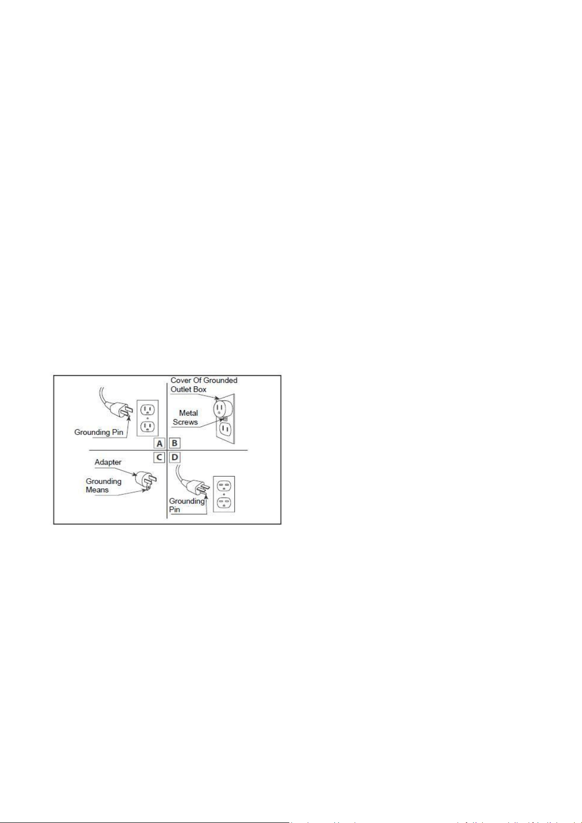
GROUNDING APPLIANCE
This appliance is for use on 120 Volts. The cord has a plug as shown in (A). An adapt er as show n in (C)
is available for connecting three-blade grounding type plugs to tw o-slot receptacles. The green
grounding lug extending from the adapt er must be connected to a permanent ground such as a
properly grounded out let box. The adapter should not be used if a three-slot grounded receptacle is
available.
To disconnect appliance, turn controls to off, then remove plug from out let.
LOCATING THE FIREPLACE
Plan where to locate and frame the fireplace. This will save time and money later when you inst all
the fireplace. Before installat ion consider the following:
1. Where the fireplace is located must allow for wall and ceiling clearances (see INSTALLATION)
2. Consider a location where the fireplace screen will not be exposed to direct sunlight from
window s or doors.
3. A 15 ampere, 120 Volt, 60 Hz branch circuit wit h proper ground must be available at the location.
Preferably a dedicated branch circuit should be provided to avoid circuit breakers to trip of fuses
to blow.
Test all aspects of its operation (manual switches, remote and heater) to make sure all components
operate correctly.
As with most electronic devices, your new electric fireplace has been designed to operate at
temperatures between 5 (41 ) and 35 (95 ). During the cold winter months, allow the
fireplace to reach room temperature before turning it on.
NOTE: There may be trace of odor during the first few minutes of initial use. This is harmless,
normal and will never occur again.
6
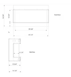
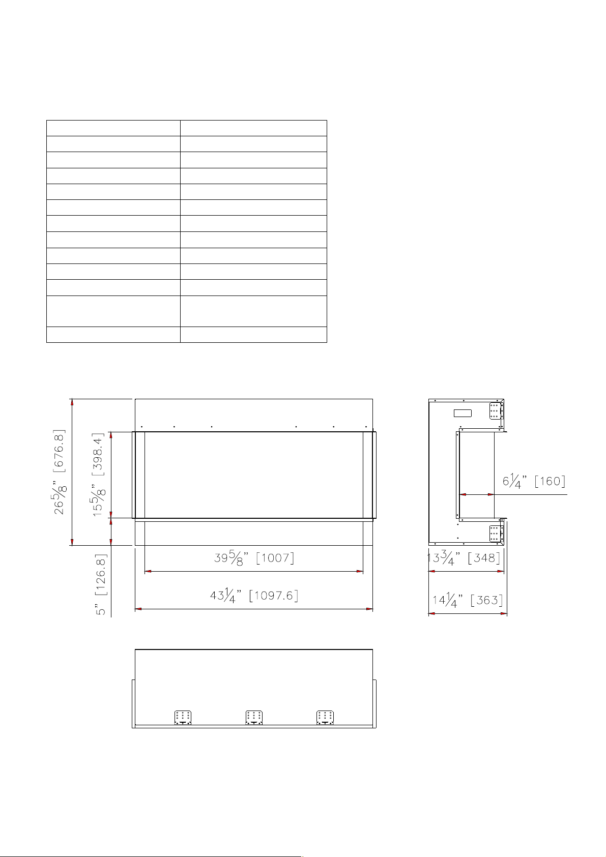
40-TRU-VIEW -XL
Descript ion Built-in Appliance
Volt age 120V AC 60Hz
Watts 1500W M ax
NO HEATER 25W
M OTOR HEATER 19W
Appliance Widt h 43 1/ 4” or 109.7 cm
Appliance Height 26 5/ 8” or 67.7 cm
Appliance Depth 14 1/ 4” or 36.3 cm
Gross Weight 121.3lbs or 55kg
Plug Location Left side
Cord Length 70 7/ 8 ” or 180 cm
Rough Wall Opening Size 43 3/ 4”× 27 5/ 8“ or
136.5 cm× 70.2 cm
BTU 4800
This appliance has been tested in
accordance wit h the UL Standard 2021
for fixed and location dedicated
electric room appliances in the Unit ed
States and Canada. If you need
assist ance during installat ion, please
cont act your local dealer.
NOTE: This appliance must be
electrically wired and grounded in
accordance with local codes. In the
absence of local codes, use the
current CSA C22.1 Canadian Electrical
Code in Canada or the ANSI/ NFPA 70
National Electrical Code in the United
States.
7
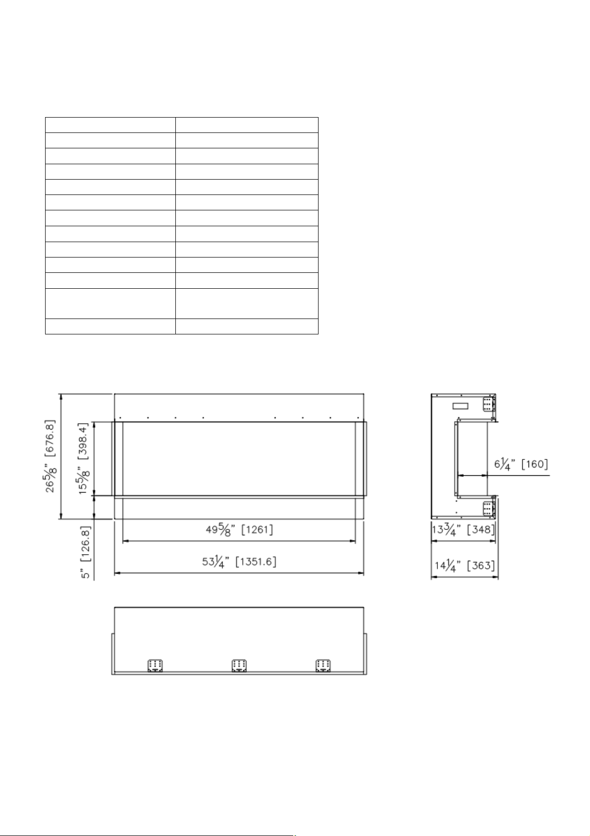
50-TRU-VIEW -XL
Descript ion Built-in Appliance
Volt age 120V AC 60Hz
Watts 1500W M ax
NO HEATER 25W
M OTOR HEATER 19W
Appliance Widt h 53 1/ 4” or 135.2 cm
Appliance Height 26 5/ 8” or 67.7 cm
Appliance Depth 14 1/ 4” or 36.3 cm
Gross Weight 123.5lbs or 56kg
Plug Location Left side
Cord Length 70 7/ 8 ” or 180 cm
Rough Wall Opening Size 53 3/ 4”× 27 5/ 8“ or
136.5 cm× 70.2 cm
BTU 4800
This appliance has been tested in
accordance wit h the UL Standard 2021
for fixed and location dedicated
electric room appliances in the Unit ed
States and Canada. If you need
assist ance during installat ion, please
cont act your local dealer.
NOTE: This appliance must be
electrically wired and grounded in
accordance with local codes. In the
absence of local codes, use the
current CSA C22.1 Canadian Electrical
Code in Canada or the ANSI/ NFPA 70
National Electrical Code in the United
States.
8
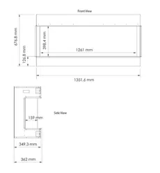
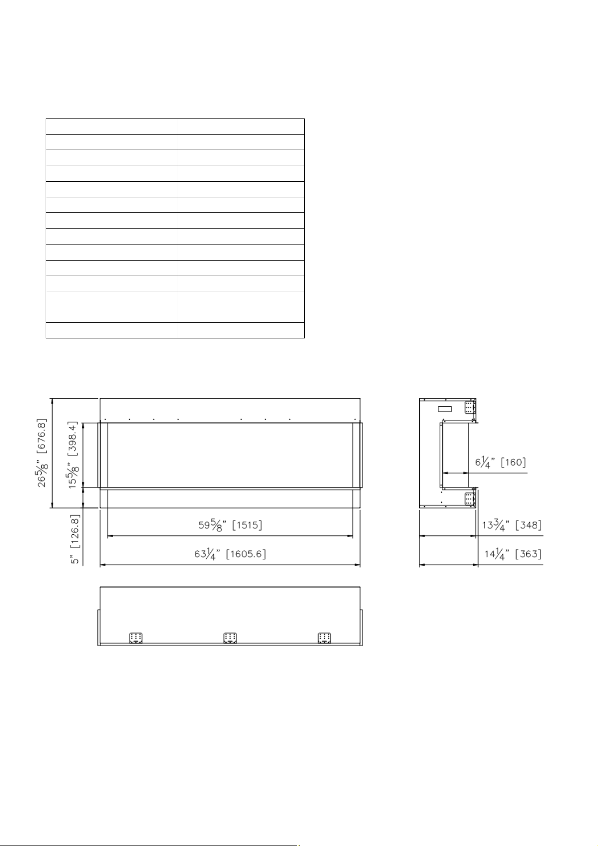
60-TRU-VIEW -XL
M odel Number Build-in Appliance
Volt age 120V AC 60Hz
Watts 1500W M ax
NO HEATER 25W
M OTOR HEATER 19W
Appliance Widt h 63 1/ 4” or 160.6 cm
Appliance Height 26 5/ 8” or 67.7 cm
Appliance Depth 14 1/ 4” or 36.3 cm
Gross Weight 141lbs or 64kg
Plug Location Left side
Cord Length 70 7/ 8 ” or 180 cm
Rough Wall Opening Size 63 3/ 4” ×27 5/ 8” or
161.9 cm
BTU 4800
This appliance has been tested in
accordance wit h the UL Standard 2021
for fixed and location dedicated
electric room appliances in the Unit ed
States and Canada. If you need
assist ance during installat ion, please
cont act your local dealer.
NOTE: This appliance must be
electrically wired and grounded in
accordance with local codes. In the
absence of local codes, use the
current CSA C22.1 Canadian Electrical
Code in Canada or the ANSI/ NFPA 70
National Electrical Code in the United
States.
×
70.2 cm
9
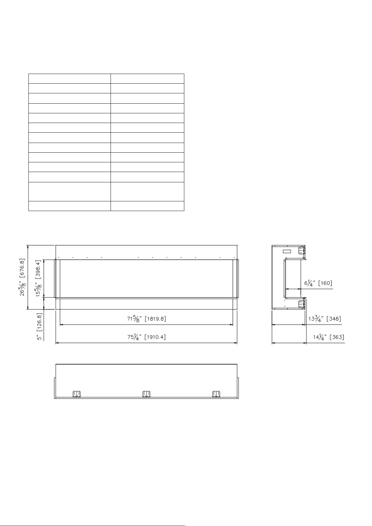
72 –TRU-VIEW -XL
Descript ion Built-in Appliance
Volt age 120V AC 60Hz
Watts 1500W M ax
NO HEATER 25W
M OTOR HEATER 19W
Appliance Widt h 75 1/ 4” or 191 cm
Appliance Height 26 5/ 8” or 67.7 cm
Appliance Depth 14 1/ 4” or 36.3 cm
Gross Weight 165lbs or 75kg
Plug Location Left side
Cord Length 70 7/ 8 ” or 180 cm
Rough Wall Opening Size 75 3/ 4”× 27 5/ 8” or
192.4 cm× 70.2 cm
BTU 4800
This appliance has been tested in
accordance wit h the UL Standard 2021
for fixed and location dedicated
electric room appliances in the Unit ed
States and Canada. If you need
assist ance during installat ion, please
cont act your local dealer.
NOTE: This appliance must be
electrically wired and grounded in
accordance with local codes. In the
absence of local codes, use the
current CSA C22.1 Canadian Electrical
Code in Canada or the ANSI/ NFPA 70
National Electrical Code in the United
States.
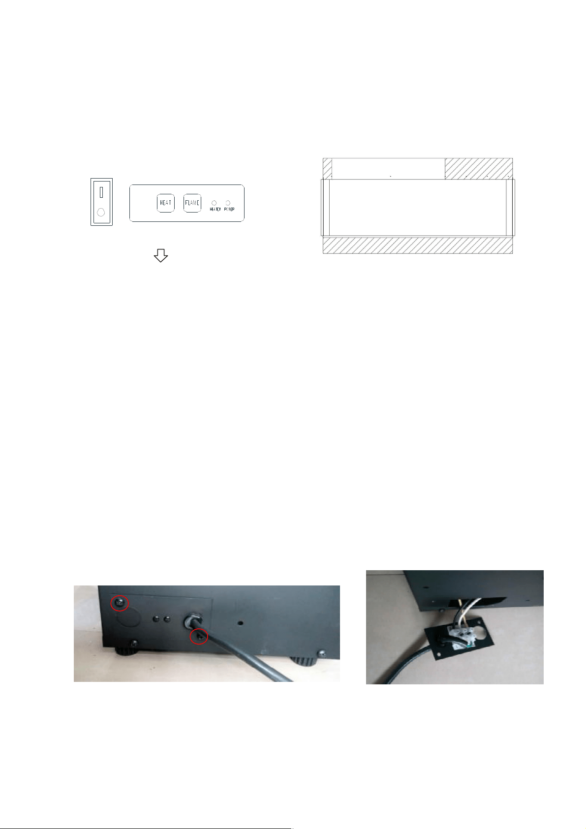
SAFETY DRILL SCREW AREA
There is a safety drill screw area as show below .
Please make sure that the fix screws are in this area.
Themanualcontrolpadposition
Safety drill screw area
(Dark area)
HARD- WIRE INSTALLATION
Turn off the appliance completely and let cool before servicing. Only a qualified service person
should service and repair this electric appliance.
If it is necessary to hard wire this appliance, a qualified elect rician must remove the cord connection,
and wire the appliance directly to the house hold wiring.
This appliance must be electrically connected and grounded in accordance wit h local codes, if hard
wired. In the absence of local codes, use the current CSA C22.1 CANADIAN ELECTRICAL CODE in
Canada or the current ANSI/ NFPA 70 NATIONAL ELECTRICAL CODE in the Unit ed States.
1. Remove the cover plate from the left side of the appliance by removing the two screw s, as
shown below. Unscrew and remove power cord.
10
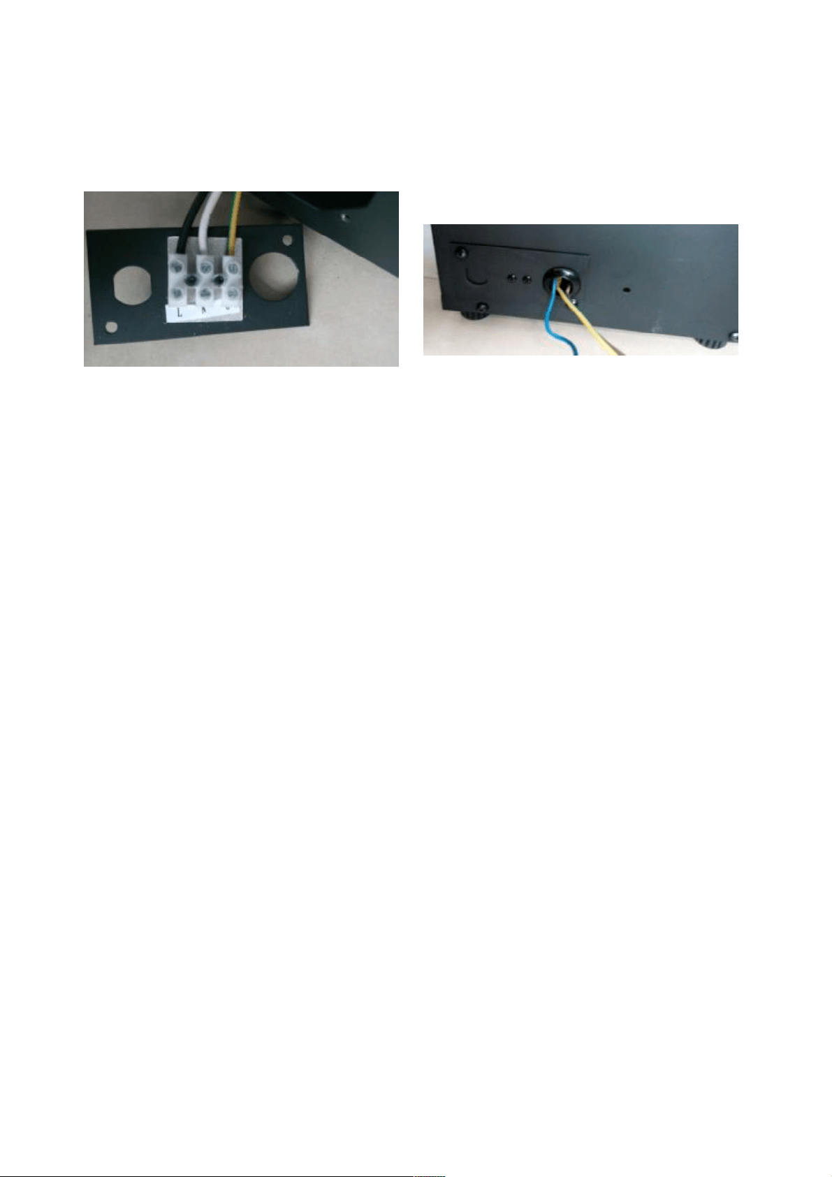
2. Attach the wiring to the junction block. Please make sure the live wire goes into the “L”, the
neut ral wire int o “N” and the ground wire into “G”.
3. Put the plate back and screw back.
FOR BATHROOM USE
If this unit is installed in a bathroom it must be protected by a GIF receptacle or circuit. If receptacle is
used it must be readily accessible.
To prevent electric shock, please be aware that this unit is an electrical appliance that is NOT watertight
and must be installed as to prevent water from entering unit. This must be installed away from shows,
tubs, etc. Never locate fireplace where it may fall into a bathtub or other water container.
All wiring connections to line power shall be in accordance with local building code requirements.
Inquires about local codes and regulations must be done prior to installation.
11
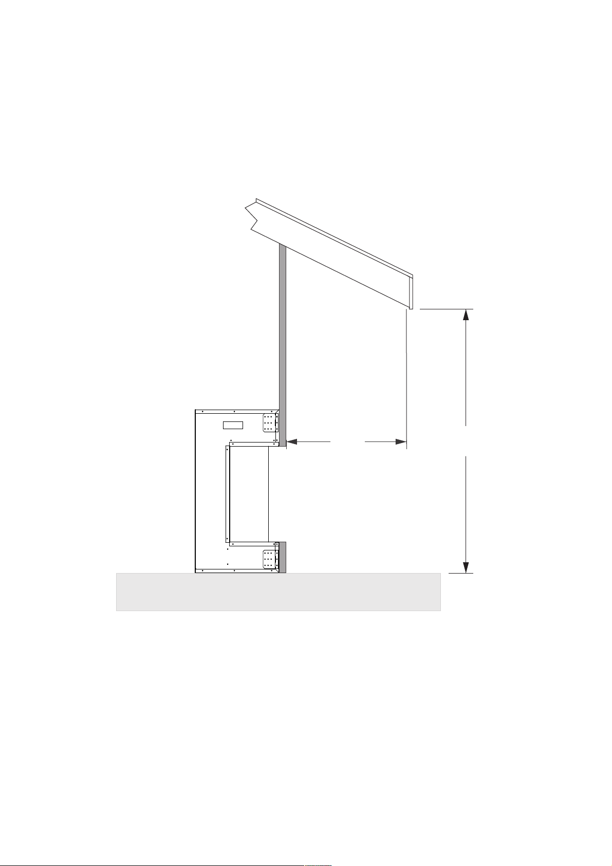
Side of
Fireplace
A
B
The overhang (A) must extend at least 1/2 the roof-line height (B).
Height is measured from the base of the fireplace.
For example: if the roof-line (B) is 8’ above the base of the fireplace,
the overhang (A) must be at least 4’.
OUTDOOR INSTALLATIONS
The TRU-VIEW-XL series electric fireplaces are suitable for installation in outdoor areas protected from
direct water impingement. In addition to maintaining the listed mantel and combustibles clearances, a
rain protection overhang factor of 1/2 shall be constructed to the front and to each side of the installed
appliance. See illustration below. All wiring connections to line power shall be in accordance with local
building code requirements. Inquires about local codes and regulations must be done prior to
installation.
12
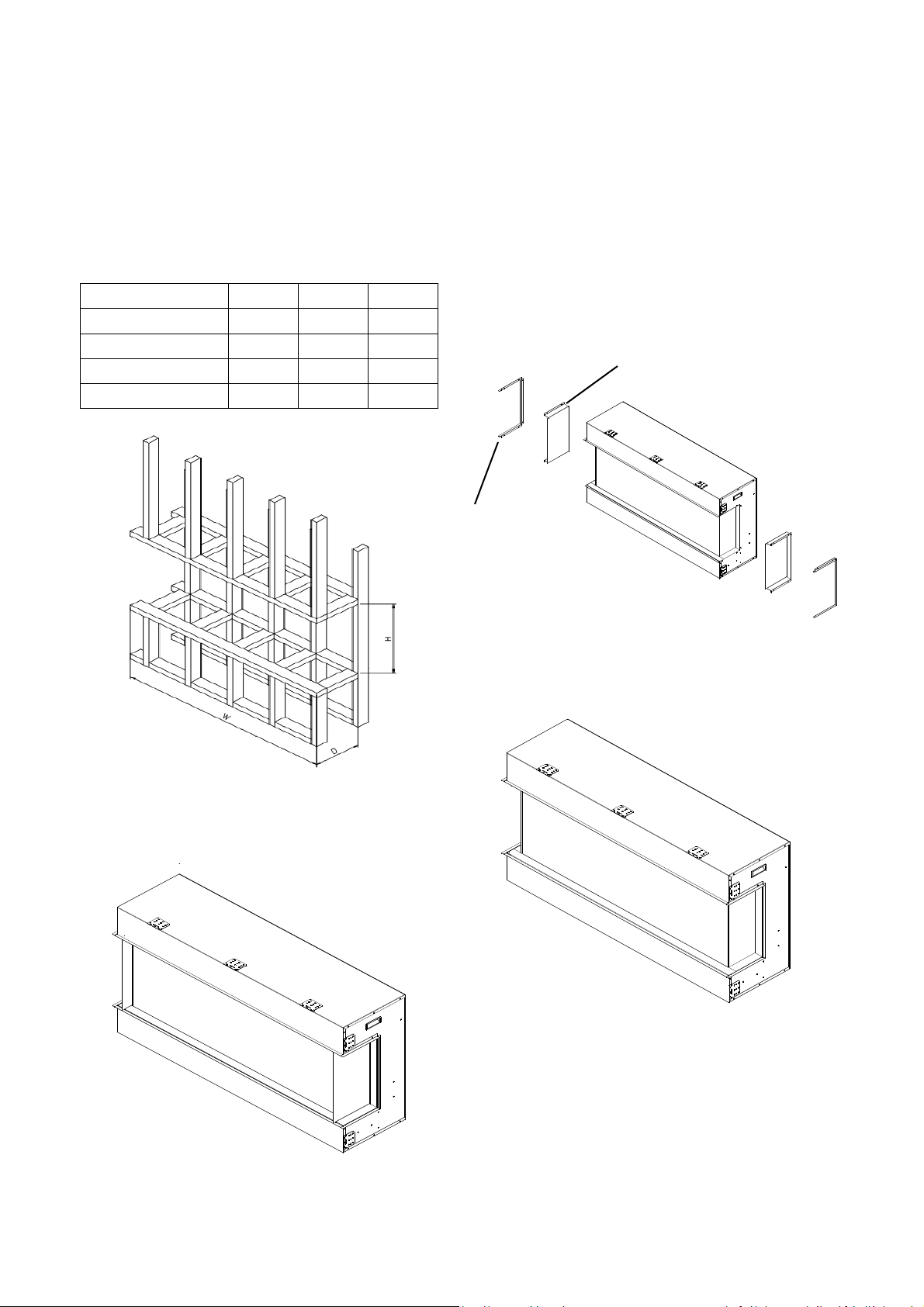
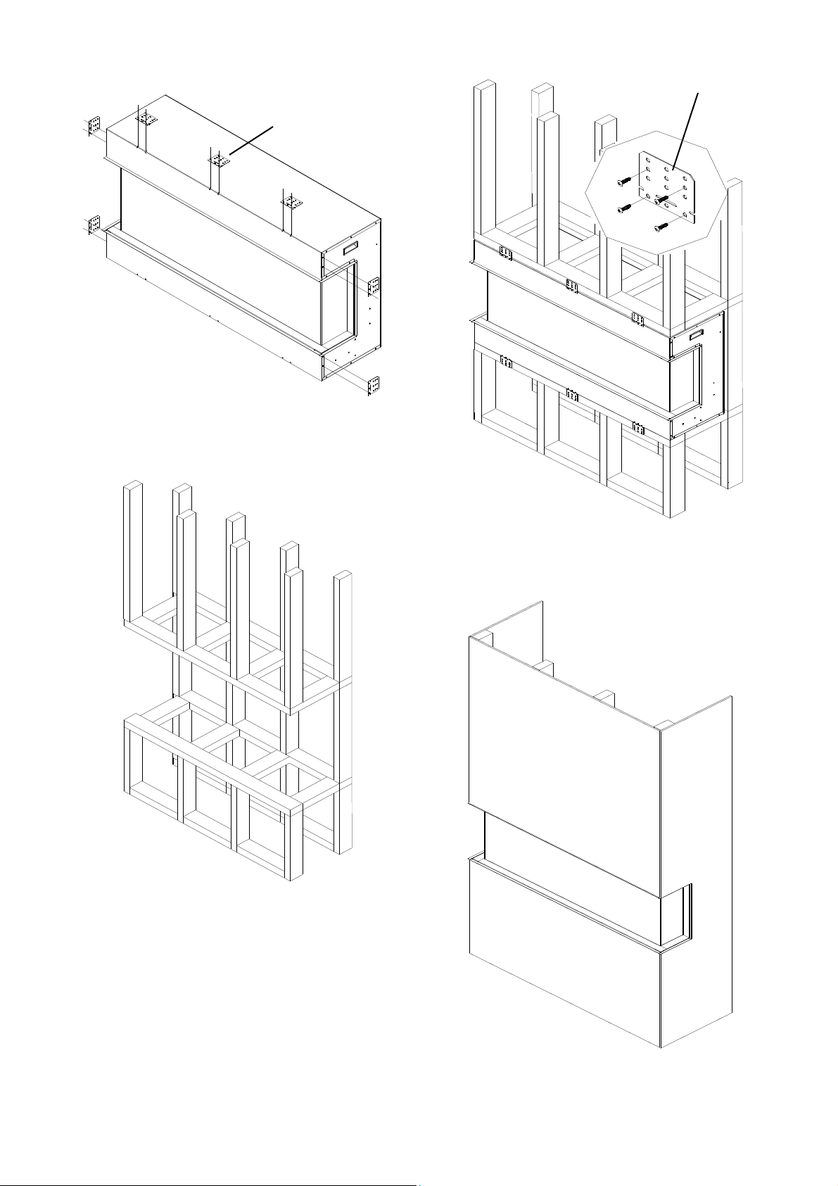
13
1. Product is fixed wit h fending bars and panels
on the left and right side.
2. Take off the fending bars and panels if you
want to view the fire from three angles.
3. Fix back the fending bar aft er the panel is
removed.
4. Remove the framing plates from the fireplace
and fix them as the picture shows.
Note: Aft er removing framing plates on the left
and right sides, screw back the screws.
IN STALLATION
The TRU-VIEW-XL models are designed to be built-in and allow for the finishing material (drywall,
stone, tile, etc) to be built right down to the glass edge.
The rough wall opening size of the fireplace:
W(") D(") H(")
50-TRU-VIEW-XL 53 3/ 4 14 3/ 4" 27 1/ 8
60-TRU-VIEW-XL 63 3/ 4 14 3/ 4" 27 1/ 8
72-TRU-VIEW-XL 75 3/ 4 14 3/ 4" 27 1/ 8
fending bar
fending panel
40-TRU-VIEW-XL 43 3/ 4 14 3/ 4" 27 1/ 8
NOTE: Due to the many different materials used on different walls, it is highly recommended that
you consult your local builder before you install this appliance.
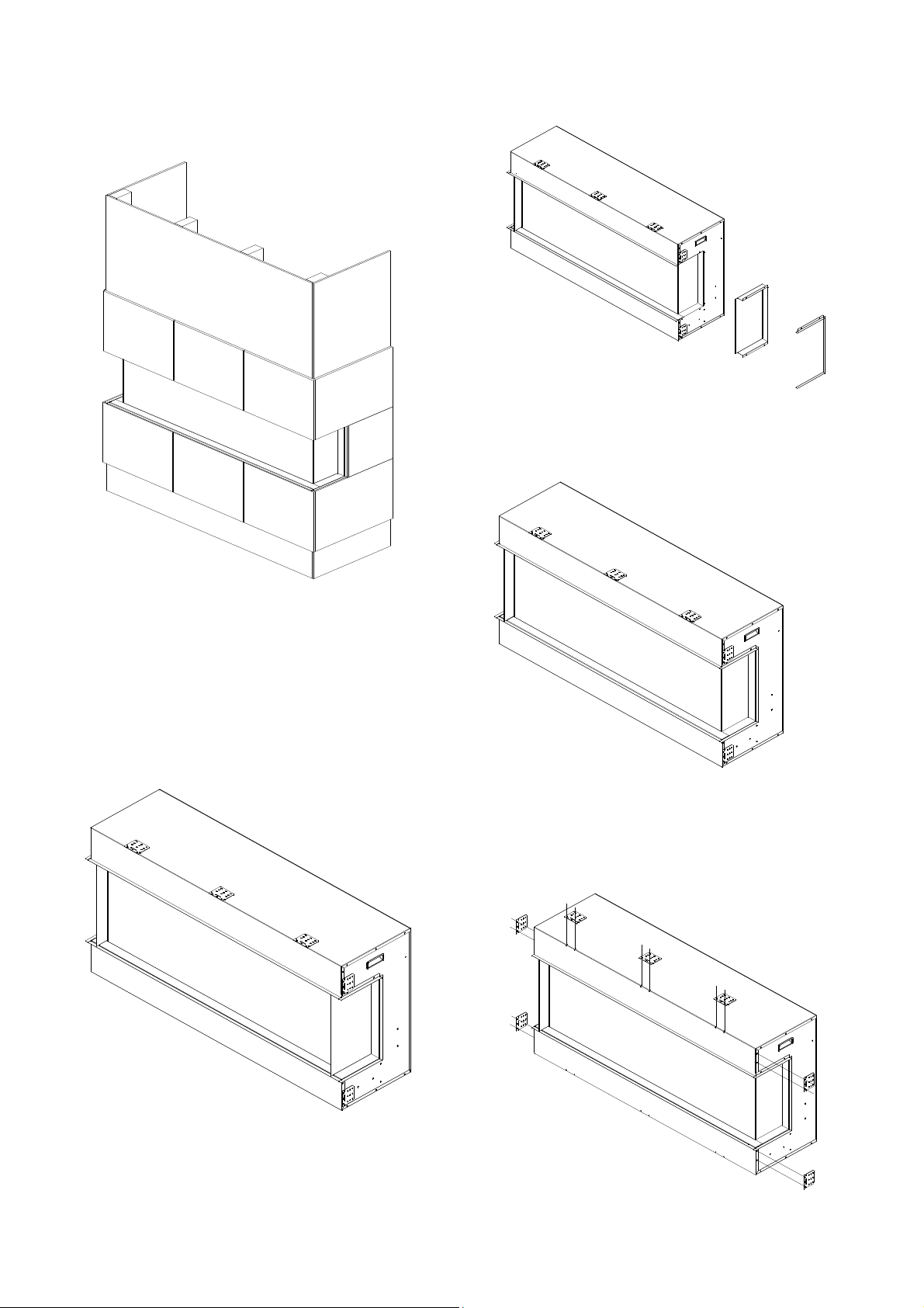
14
5. M ake an opening for the fireplace according
to request ed measurement .
framing plat e
framing plat e
7. After checking that the fireplace operates
properly, cover the glass panels with prot ective
plastic bag and install plyw ood or drywall.
6. Insert the fireplace int o the wall opening.
Drive the mounting screw s into the frame plates
on the unit and the wall studs. To fix the bottom
of the fireplace and the wall studs with the
framing plates that you’ve removed from left
and right side of the fireplace at STEP 4. Plug in
and check if the fireplace works.
15
8. Decorat e the plywood or drywall wit h glazed
tile, wallpaper, et c.
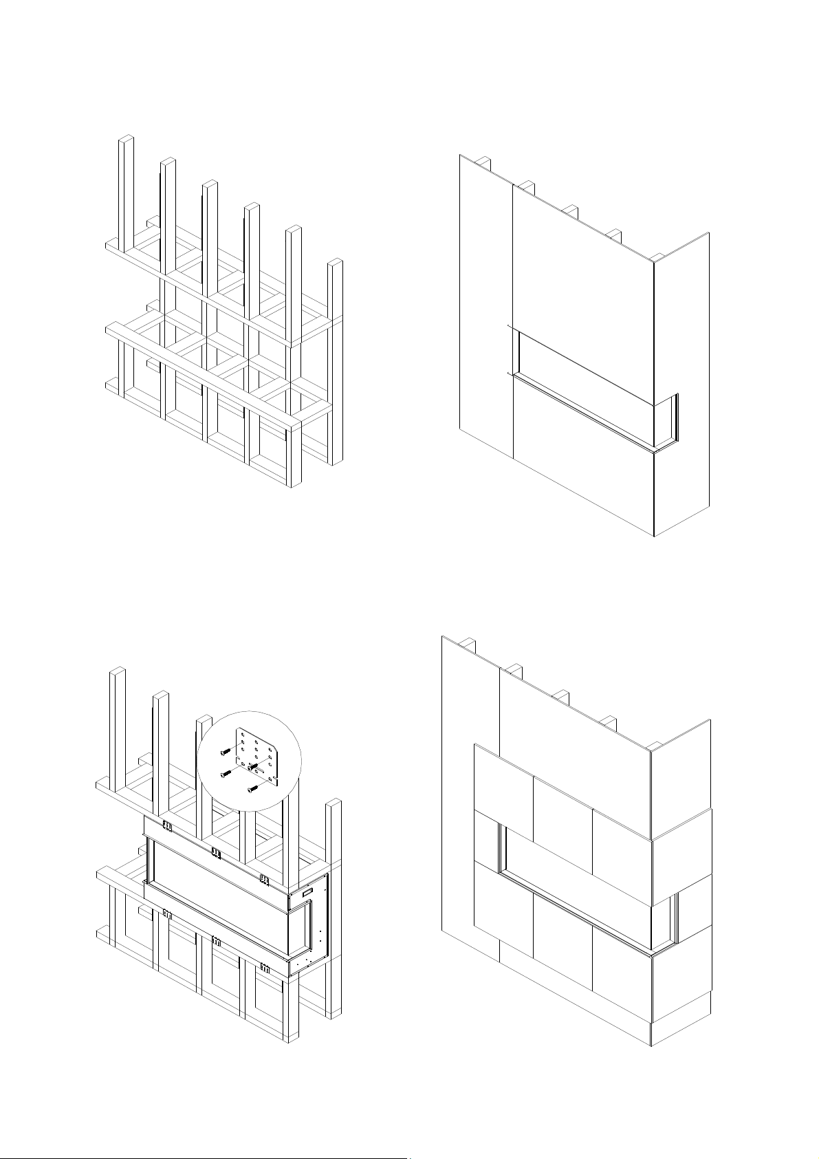
3. After the fending panel is removed, screw
back the bar.
4. Remove the framing plates from the fireplace
and fix them as the picture shows.
Note: Aft er removing framing plates on the left
and right sides, screw back the screws.
Installation for Front and Right Side
View ing
1. To install the fireplace where the left side is
close to a wall, and you want to view the fire
from front and right side, take off the fending
panel on the right.
fending bar and panel.
2. Unscrew 7 screw s on the right side that fix
the fending bar and panel and then take off the
16
8. Decorat e the plywood or dryw all wit h glazed
tile, wallpaper, et c.
5. M ake an opening for the fireplace according
to request ed measurement .
7. After checking that the fireplace operates
properly, cover the glass panels with prot ective
plastic bag and install plyw ood or drywall.
6. Insert the fireplace int o the wall opening.
Drive the mounting screw s into the frame plates
on the unit and the wall studs. To fix the bottom
of the fireplace and the wall studs with the
framing plates that you’ve removed from left
and right side of the fireplace at STEP 4. Plug in
and check if the fireplace works.
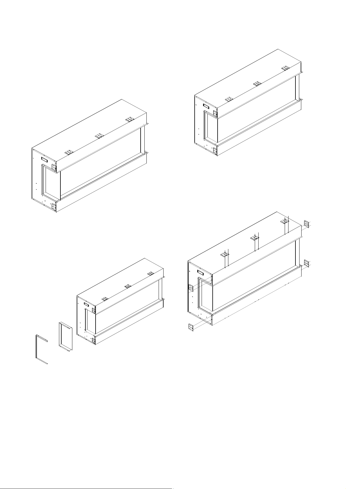
17
3. After the fending panel is removed, screw
back the bar.
4. Remove the framing plates from the fireplace
and fix them as the picture shows.
Note: Aft er removing framing plates on the left
and right sides, screw back the screws.
Installation for Front and Left Side
View ing
1. Install the fireplace where the right side is
close to a wall, and you want to view the fire
from front and left side, take off the fending
panel on the left .
5. M ake an opening for the fireplace according
to request ed measurement .
2. Unscrew 7 screw s on the right side that fix
the fending bar and panel and then take off the
fending bar and panel.

18
8. Decorat e the plywood or drywall wit h glazed
tile, wallpaper, et c.
7. After checking that the fireplace operates
properly, cover the glass panels with prot ective
plastic bag and install plyw ood or drywall.
6. Insert the fireplace int o the wall opening.
Drive the mounting screw s into the frame plates
on the unit and the wall studs. To fix the bottom
of the fireplace and the wall studs with the
framing plates that you’ve removed from left
and right side of the fireplace at STEP 4. Plug in
and check if the fireplace works.

19
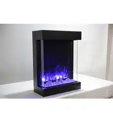
M edia Options
FI-109-DIAM OND
3 glass nugget s, 1 bag of clear, 1 bag of small
clear, 1 bag of clear diamond and 1 bag of blue
diamond.
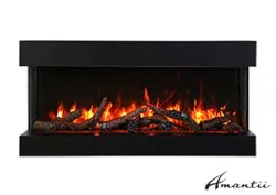
The TRU-VIEW models also come wit h the DESIGN-M EDIA-11PCE Kit feat uring an 11 pcs deluxe log set ,
pebbles, stones, black glass and an assort ment of vermiculit e embers. The DESIGN-M EDIA kit s come in
a separat e box.
The 40-TRU-VIEW-XL is shipped with 1 set of FI-109-DIAMOND, 50-TRU-VIEW-XL and 60-TRU-VIEW-XL
are shipped with 2 sets of FI-109-DIAMOND, 72-TRU-VIEW-XL is shipped with 3 sets of
FI-109-DIAMOND.
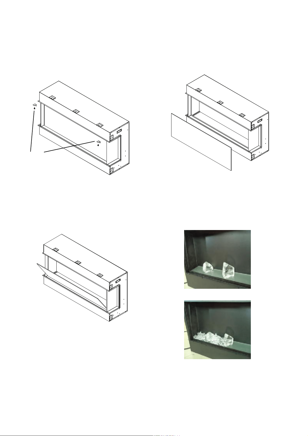
4. Installing the fire glass media. Pour the fire
glass media int o the tray as show n below .
Feel free to use any combination of fire glass
media that you find most appealing.
5.Put back the front glass and screw back the
bracket.
3. Take off the front glass panel and put it in safe place.
1. Unscrew 2 screws and take off two brackets which
are fending the front glass panel.
Screws and brackets
2. Aft er the brackets are removed, the front glass panel
will fall down aut omatically.
M edia Operation
20
21
OPERATION
The fireplace can be operated either by the switches located on the left bottom of the fireplace unit
or by supplied remot e cont rol.
Plug the fireplace into a 15 Amp wall socket .
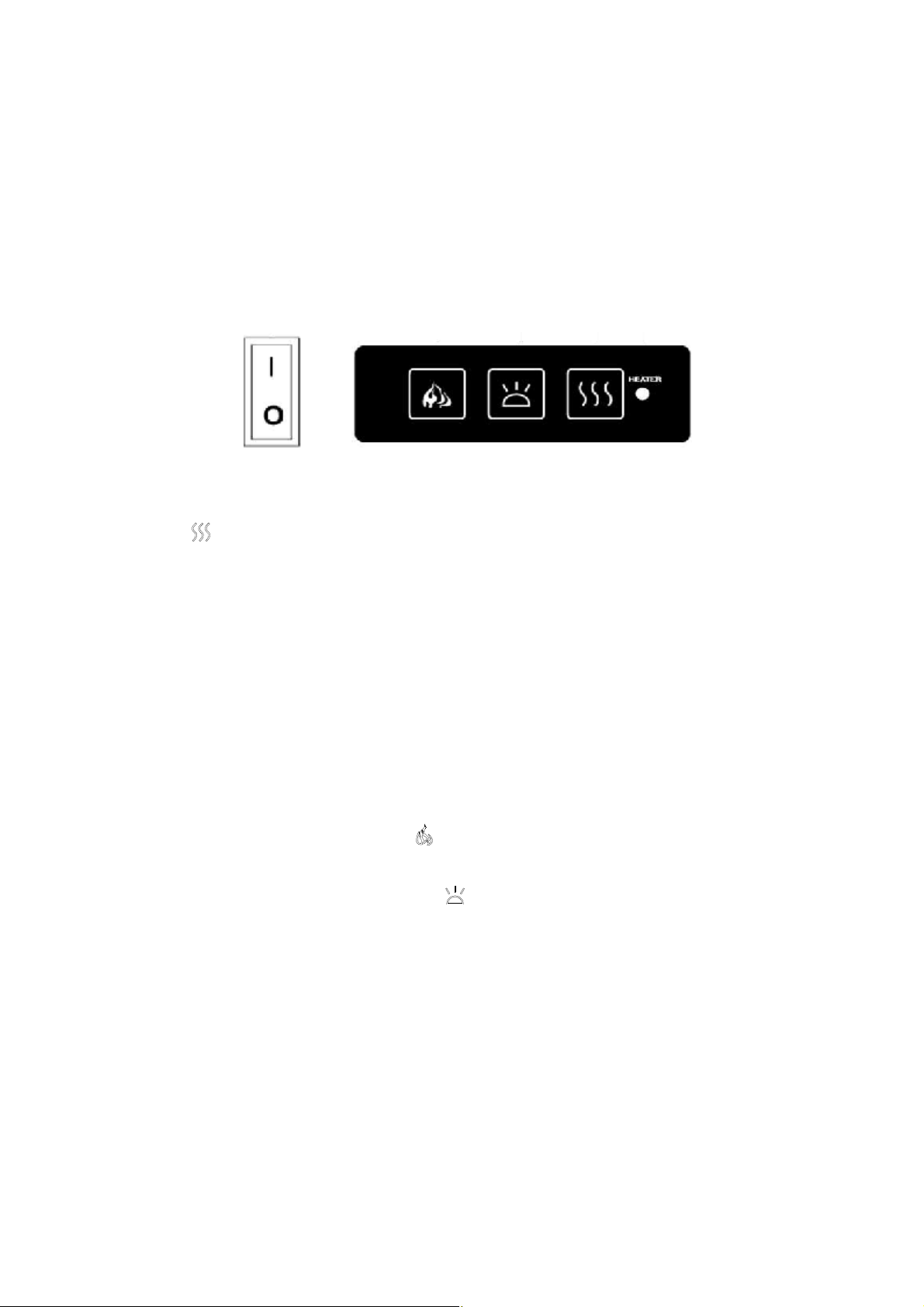
M ANUAL OPERATION
1. The main power ON/ OFF sw itch in posit ion O, the fireplace is OFF.
2. When main power ON/ OFF swit ch is at position I, the fireplace is ready to use.
3. Press the
butt on repeat edly to set the heat er to desired heat set t ing. The heater indicator
LED will glow which show s the current heater settings.
a) RED 1500W HEAT OUTPUT
b) BLUE 750W HEAT OUTPUT
c) PURPLE AUTO M ODE
AUTO M ODE
Under this mode the heat er will automatically turn ON at high heat setting 1500W heat out put when
the room temperature drops below 22℃(72 ℉ ). When the room temperat ure is between
22-25℃(72-77 ℉ ) the heater output will sw itch to low heat set t ing 750W. When the room
temperat ure goes above 25℃(77℉) the heat er will be turned off and the cycle will continue. The
LED indicator will be PURPLE in colour under this mode.
4. Flame effect: Press the button marked
to adjust the flame brightness. The flame bright ness
will cycle through –Low -M edium-High -OFF.
5. M ood light effect: Press the button marked
to change the mood light colour.
NOTE: If operated at the Low heat setting, the fireplace will not provide as much heat out put as in
the High heat setting, however the low set t ing will not require as much elect rical pow er to operate.
To avoid overloading a circuit, do not plug the fireplace into a circuit that already has ot her
appliances working. When the fireplace is not in use swit ch off and unplug.
SAFETY CUT-OFF
l This appliance is fitt ed wit h a safet y cut-off which will operate if the fireplace overheats (eg. Due
to blocked air vent s). For safet y reasons, the fireplace will NOT aut omatically reset.
l To reset the appliance, disconnect the appliance from the main supply f or at least 10 minut es.
Reconnect the main pow er supply and put the main power switch to the ON position.
22
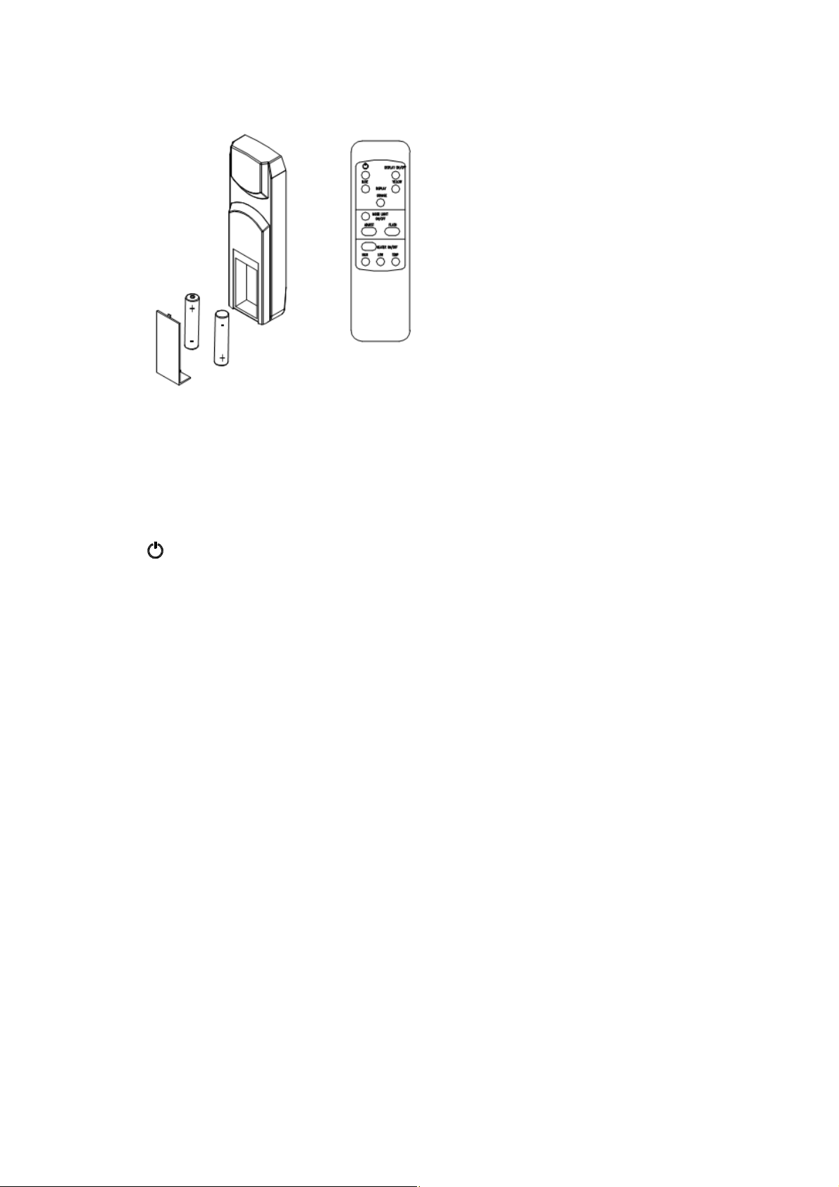
REM OTE CONTROL OPERATION
For remote to funct ion make sure the heat er is plugged in and main power sw it ch located on the
bottom left hand side is at posit ion I.
When operating the remote make sure you point the remote to the centre of the fireplace and make
sure each time you press the button. The buzzer inside the unit will beep once. It takes some time for
the receiver to respond to the transmit t er. Do not PRESS the butt ons more than once within two
seconds for correct operation.
Pow er on
butt on: The power-on button at top left corner of the remote is the main ON/ OFF
power button. This will turn off all the functions and the fireplace will be in standby mode.
DISPLAY ON/OFF button: Switching the fireplace flame and tray light ON/ OFF. It has functions of
setting memory.
DISPLAY BLUE button: Adjust the blue color brightness of flame and tray.
DISPLAY YELLOW button: Adjust the yellow color brightness of flame and tray.
DISPLAY ORANGE button: Adjust the orange color brightness of flame and tray.
M OOD LIGHT ON/ OFF button: Swit ching the mood light ON/ OFF.
ADJUST button: Swit ching the color of the mood light.
FLASH button: Swit ches mood light into flash mode, this cycles through all mood light colors.
HEATER ON/OFF button: Switching the heater ON/OFF. It has functions of setting memory.
HIGHT button: Press the high button to switch the heater to high heat setting 1500W.
LOW button: Press the low button to switch the heater to low heat setting 750W.
TEMP. button: Press the TEMP. button to switch the heater to AUTO mode. Under this mode
the heater will operate in similar way as explained above for the manual operation.
23
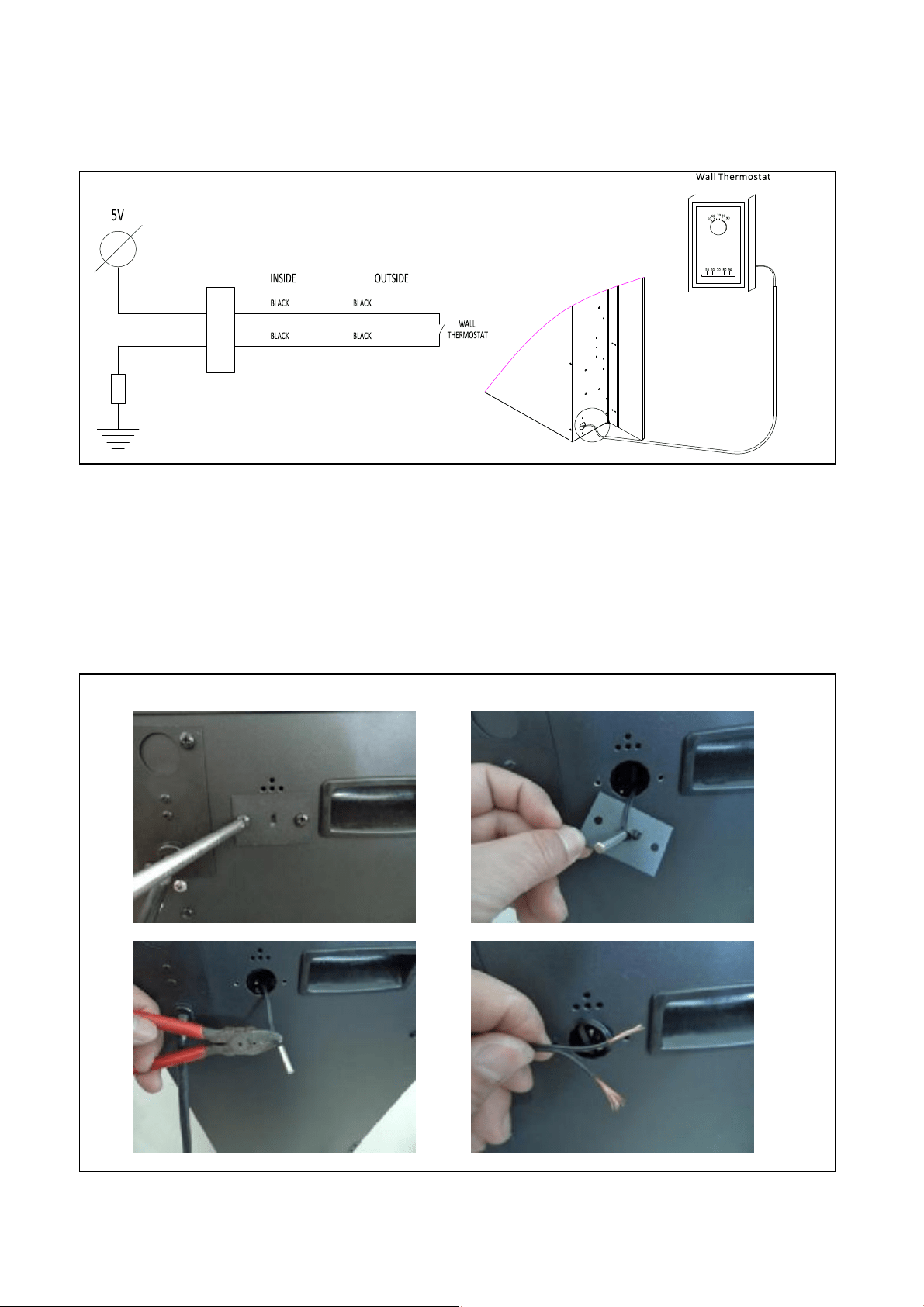
INSTALLING W ALL THERM OSTAT
W ALL THERM OSTAT W IRING DIAGRAM S
W ire the wall thermostat prior to installing the fireplace.
W ALL THERM OSTAT W IRING(24 VAC)
Install W all Thermostat per instructions provided with kit and per the follow ing information:
1. Turn off circuit breaker.
2. Remove cover plate located on the left side of appliance.
3. Pull the wire out and cut the inside thermost at . Connect the wires to the wall thermostat as
shown below. Follow instructions provided with wall swit ch kit.

24
REPLACEMENT PARTS
This list contains replacement parts
NO PART NUMBER DESCRIPTION QTY.
40-TRU-VIEW-XL 50-TRU-VIEW-XL 60-TRU-VIEW-XL 72-TRU-VIEW-XL
1 10701281 10701216 10701217 10701218 FRONT CLEAR GLASS 1
2 10201505 ADJUSTABLE SCREW 2
3 3123010 FRONT CLEAR GLASS
BRACKET
2
4 10702200 10702168 10702169 10702170 BOTTOM TRAY GLASS 1
5 10701284 10701219 10701220 10701221 BACK GLASS WITH
BLACK PLASTIC
1
6 10701222 SIDE CLEAR GLASS 2
7 601136B 601136B 601136B 601137B LED STRIP FOR TRAY
AND FLAME
8 3151505 3123505 3124505 3125505 FLICKER ASSEMBLY 1
9 10101225 FLAME MOTOR 2
10 10104002 SWITCH 1
11 601036 MANUAL CONTROL 1
12 601092C CIRCUIT BOARD 1
13 602082B BLOWER AND HEATER
ASSEMBLY
1
14 601002B REMOTE RECEIVER 1
15 THE WHOLE METAL BOX 1
16 10125021 10125022 10125023 10125024 TOP LED STRIP 1
17 10105063 REMOTER 1
*16 and 17 do not show in the exploded picture.
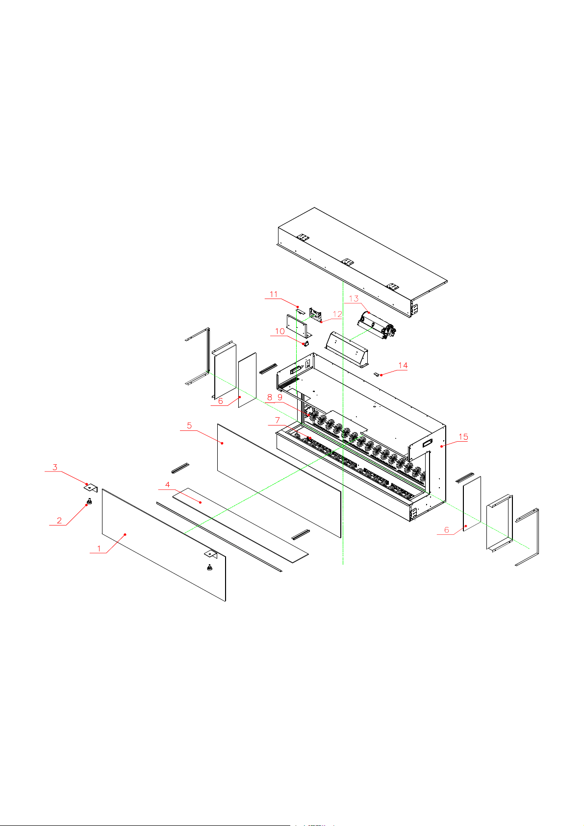
EXPLODED VIEW
25
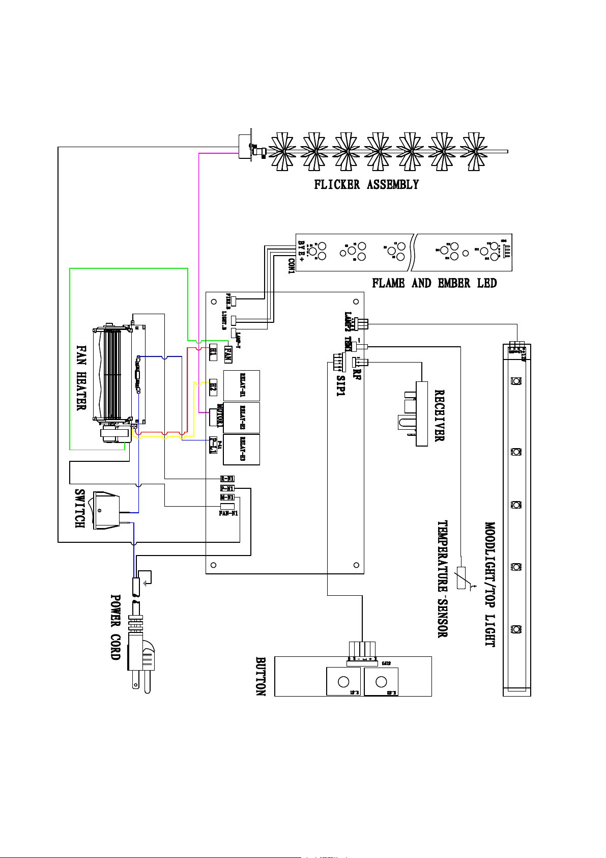
26
W iring Diagram

27
TROUBLE SHOOTING
PROBLEM POSSIBLE CAUSE SOLUTION
Dim or no flame Flame LED’s are burnt out Inspect the LED’s and replace them if
necessary.
Ember bed is not
glowing or dimming
Ember LED’s are burnt out Inspect the ember bed LED’s and
replace them if necessary.
Appliance has overheated and
safety device has caused the
thermal switch to disconnect
Turn off the main switch, allow
appliance to cool for 10 minutes, then
turn it on.
House circuit breaker has
tripped
Reset house circuit breaker.
Appliance turns off and
will not turn on
Appliance’s fuse has blow n Replace the fuse.
Appliance is not plugged into an
electrical outlet
Check plug and plug in.
Appliance has overheated and
safety device has caused the
thermal switch to disconnect
Turn off the main switch, allow
appliance to cool for 10 minutes, then
turn it on.
Appliance will not come
on when switch is
flipped to ON
Circuit board is burnt out Inspect the circuit board and replace
it if necessary.
No warm air coming out
of appliance
Heat er is burnt out Inspect the burner and heater
assembly and replace it if necessary.
Flame sput t ers
Flame mot or is defective. Call a qualified service technician and
replace flame mot or.
Remote Control does
not work.
Low bat t eries.
Unit switch in “O” posit ion.
Replace AAA bat t eries in remote
cont rol.
Turn the swit ch in “I” position.
Flame is fixed. Wiring may be loose or the
flame mot or may be defective.

28
SERVICE HISTORY
This heat er must be serviced annually depending on usage.
Date Dealer
Name
Service technician
Name
Service Performed Special Concerns
NOTES:
29