Documents: Go to download!
User Manual
- Owner's manual - (English)
- CMXGTAM202501 - Instructional Manual - Type 2020 - (English)
- CMXGTAM202501 - Instructional Manual - Type 2020 - (English)
User manual of Craftsman CMXPGRA18 (20 pages)
- OPERATING CONTROLS
- MAINTENANCE
- STORAGE
- TROUBLESHOOTING
Table of contents
Snow Blower User Manual
OPERATING CONTROLS
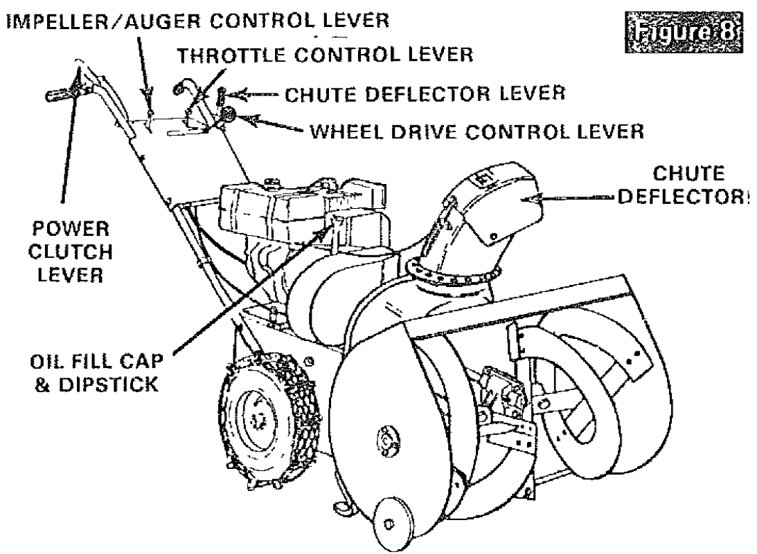
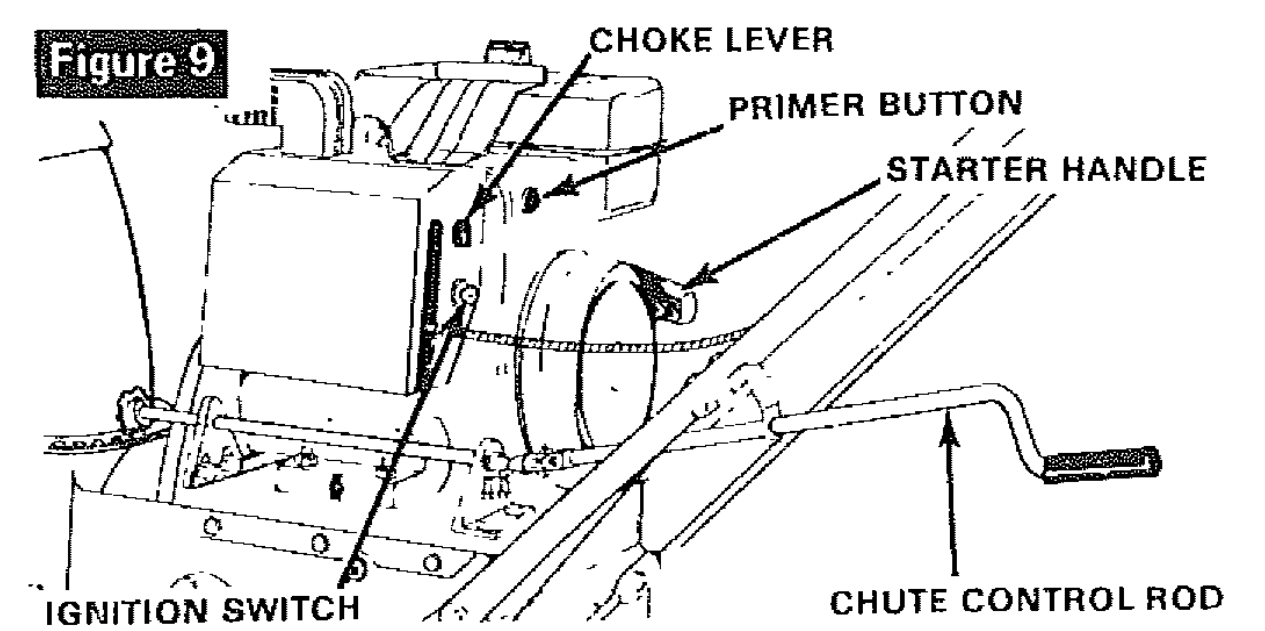
Operating controls (figures 8 & 9) and their functions are as follows:
- Power Clutch Lever The power clutch lever controls forward or reverse motion of the unit when the wheel drive control lever is in the appropriate position. When the operator's hand is removed from the power clutch lever, tension is removed from drive belts, therefore unit motion and impeller/ auger rotation stop. Engage slowly but firmly and all the way down against hand grip.
- Impeller/Auger Drive Control Lever - Used to disengage power to impeller/ auger without interfering with power to drive wheels. Pull up to engage. Push down to disengage. NOTE: Power clutch lever must be in released (disengaged) position before impeller/ auger fever position is changed.
- Throttle Control Lever - This snow thrower is equipped with a control panel mounted throttle control lever used to control speed of engine. There are three positions on the throttle control - Stop - Slow - Fast.
- Wheel Drive control lever - Used to select desired unit speed or direction. Choice of five forward speeds, neutral and reverse.
- Chute Deflector Lever - The distance snow will be discharged can be adjusted by raising chute deflector (figure 8) for more distance, or lowering for less distance. Pull lever up to top notch for most distance. Push lever down to bottom notch for least distance.
DANGER: Do not put hands in or near the deflector chute while the engine is running.
- Chute Control Rod - Used to change direction of snow discharge. Turn handle counterclockwise to turn chute to left. Turn handle clockwise to turn chute to right. All snow can be discharged to one side by changing chute direction when changing direction of travel.
- Choke Lever - Set choke lever to FULL CHOKE position to start engine.
- Primer Button - Used to inject fuel directly into carburetor manifold to insure fast starts.
- Ignition Switch - Switch must be turned to ON position to start engine and turned to OFF position to stop engine.
- Starter Handle - This unit is equipped with a recoil starter.
SNOW THROWER OPERATION
The most effective use of the snow thrower will be established by experience, taking into consideration the terrain, wind conditions and the depth and weight of the snow. It is the wind conditions and building location which will determine the direction of the discharge chute. Since the wind will tend to blow the discharged snow back into the cleared area, it will be necessary to change the chute direction to offset this condition. NOTE: Do not throw snow tovvards a building as hidden objects could be thrown with sufficient force to cause damage.
To engage the self-propelling drive mechanism, proceed as follows:
- Start the engine as described in paragraph To Start Engine.
- Using the chute control rod (figure 9), position the discharge chute so as to discharge the snow with the wind.
- Select proper speed for snow conditions as outlined below and set wheel drive control lever to desired position.
- Number 1 position is for extra deep, wet, heavy Snow.
- Number 2 position is for deep, wet, heavy snow. Experience will help make choice between position 1 and 2.
- Number 3 position is for light fluffy snow.
- Number 4 position is mainly for transporting unit over bare or plowed areas, but may be used for very light snow.
- Number 5 position is for transporting unit over bare or plowed areas.
- Set the impeller/ auger control lever to the ON position.
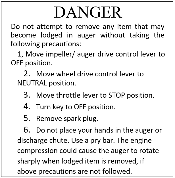
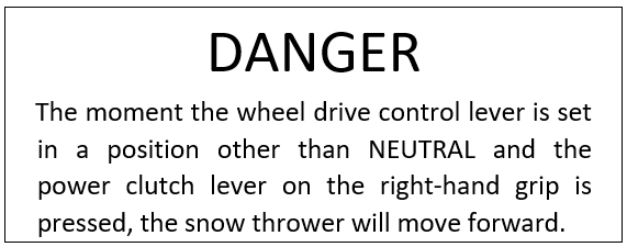
- Press the power clutch lever to begin impeller/ auger rotation and forward motion. As the unit starts to move, maintain a firm hold on the handles and guide the snow thrower along the cutting path.Do not attempt to push the unit.
- To disengage the drive mechanism: Release the power clutch (ever. Set the wheel drive control lever to the NEUTRAL position. Set the impeller/auger drive control fever to the OFF position.
- To move unit backwards: Place wheel drive control lever in REVERSE position and press the power clutch lever. To stop backward motion: Release pressure from power clutch lever. Return wheel drive control lever to NEUTRAL position.
BEFORE STARTING ENGINE
A can of high quality 5W-20 motor oil is supplied with your unit.
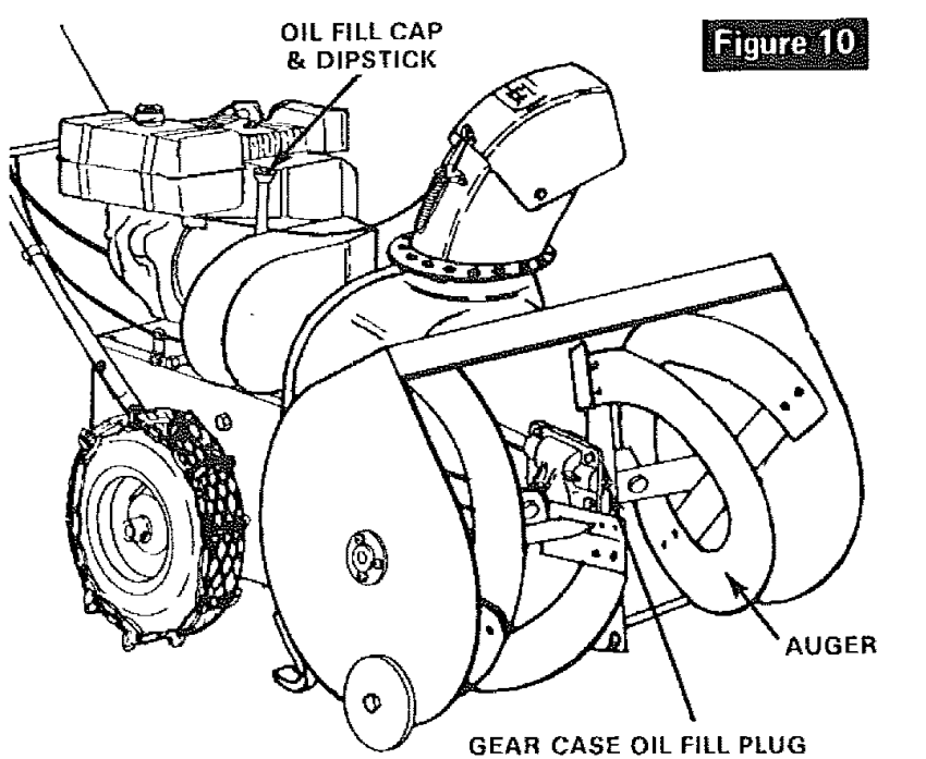
- Remove the oil cap and dipstick (figure 10) and fill crankcase to the FULL line on dipstick (approximatey 1 1/2 pints),
- Replace the oil cap and dipstick and tighten securely.
- Atways check oil level before starting the engine and after each five hours of continuous use. Add oil as required. Do not overfill.
4. Change crankcase oil after the first 2 hours of operation and after each 25 hours of operation thereafter, or at the beginning of each season, whichever comes first.
5. To drain the oil, see paragraph Lubrication in Maintenance section of this manual.
6. Fill gas tank with clean, fresh, unleaded grade automotive gasoline. Leaded regular grade gasoline is an acceptabfe substitute. Do not use Ethyl or high octane gasoline, Be certain container is clean and free from rust or foreign particles. Never use gasoline that may be stale from long periods of storage in the container.

7. Check oil level in gear case by removing oil level fill plug (figure 10). Oil should be visible in hole. If not, insert a funnel that has an adjustable neck and add SEARS SAE-30 (or equivalent) engine Oit until it starts to run out of hole. Replace plug and tighten securely.
TO START ENGINE
The snow thrower engine is equipped with a recoil starter. The operation of this engine is controlled by the throttle control lever (figure 8). Before starting the engine, be certain that you have read and followed all the instructions on the preceding pages.
- . Move wheel drive control lever (figure 8) to NEUTRAL position.
- Move impeller/ auger control lever (figure 8) to OFF position.
- Rotate ignition switch key (figure 9) clockwise to ON position.
- Move throttle control lever (figure 9) to FAST position,
- Move choke lever (figure 9) to FULL CHOKE position. NOTE: Do not choke a warm engine.
- Push primer button (figure 9) 2 times, NOTE: Do not prime a warm engine.
- Pull starter handle (figure 9) rapidly. NOTE: Do not allow starter handle to snap back but rewind slowly while keeping a firm hold of starter handle.

8. As engine warms up and begins to operate evenly, move choke lever slowly to OFF position. If engine falters, return to 1/2 choke until it runs smoothly, the move to OFF choke position. NOTE: Allow the engine to warm up for a few minutes as the engine will not develop full power until it reaches operating temperature,
9. Run engine at or near top speed. NOTE: To help prevent possible freeze-up of rewind starter, proceed as follows after each snow blowing job:
A. With engine running, putl starter rope hard with a continuous full arm stroke three or four times. Pulling of starter rope will produce a loud clattering sound. This is not harmful to the engine or starter.
10. To stop forward motion, release power clutch fever (figure 8) on right handle. To stop engine, move throttle control lever to STOP position and move ignition switch key to OFF position. NOTE: To hetp prevent possible freeze-up of engine controls, proceed as follows after each snow blowing job:
A. With engine not running, wipe all snow and moisture from carburetor cover in area of control levers. Also move control levers backward and forward several times.
IMPORTANT: After each use of the snow thrower, stop the engine, remove the ignition key, remove all accumulated snow from the unit and wipe clean. Store the snow thrower in a protected area.
NOTE: To prevent or cure iceing of cables and control, a deicer can be used. De-icer is available in the automotive department of your nearest SEARS Store.
CAUTION Pay close attention to instruction on the de-icer container. Also be extra careful that no de-icer comes in contact with muffler or any other hot area on or near engine.
MAINTENANCE
DRIVE BELT REPLACEMENT
The drive belts on this unit are of special construction and should be replaced with original equipment belts available from your nearest SEARS Store or Service Center. To Replace Unit Drive Belt (belt nearest engine):
- Remove belt cover (figure 11).
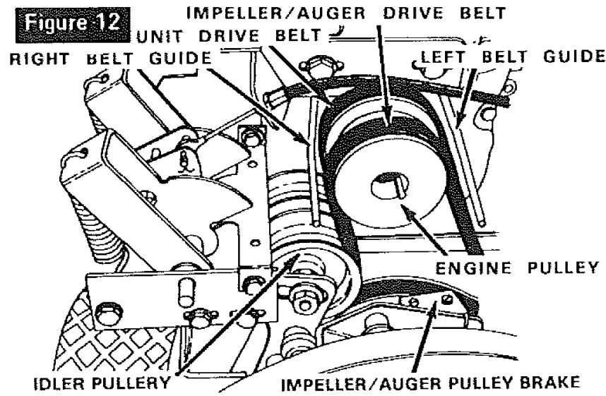
- Loosen screw holding left belt guide (figure 12) and swing guide away from pulley. Retighten screw.
- Loosen screw holding right belt guide (figure 12) and swing guide away from pulley. Retighten screw.
- Roll bett off engine pulleyr NOTE: It wilt be necessary to roll impeller/ auger drive belt off engine pulley to allow unit drive belt to be removed from engine pulley.
- Remove belt by threading up between large drive pulleys.
- Install new belt in reverse order.

To Replace Impeller/ Auger Drive Belt {belt farthest from engine):
- Remove belt cover (figure 11 ).
- Stand unit up on auger end, remove screws from bottom cover and remove cover.
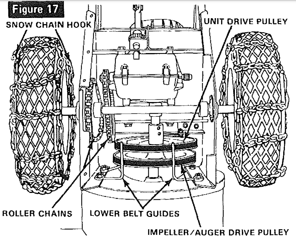
- Loosen screws holding lower belt guides (figure 17) and swing guides away from belt.
- Roll belt off impeller/ auger drive pulley and engine pulley and remove between drive pulleys.
- Install new belt in reverse order.
- Move lower belt guides back to within 1/16 inch of impeller/auger drive pulley and tighten screws.
- Replace bottom cover and return unit to operating position.
- Adjust right and left belt guides (figure 12) as instructed in Step 3 in paragraph Drive Belt Adjustment in Adjustment section of this manual.
- Replace belt cover.
SHEAR BOLT REPLACEMENT
The main auger assembly is made up of a right and left auger. Each is secured with a special bolt (figure 18) that acts as a shear bolt. These bolts are designed to break if an object becomes lodged in the auger. Three spare shear bolts and nuts have been furnished with your unit. If additional bolts are required, order genuine replacement bolts. Use of a herder bott will destroy the protection provided by this special bolt. To replace a broken shear bolt, proceed as follows:
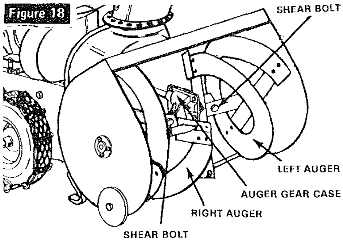
- Remove the parts of the broken bolt.
- Align the hole in the auger with the hole in the auger shaft. Install new shear bolt,
ROLLER CHAIN REPLACEMENT
There are two roller chains on this unit as shown in figure 17. Bottom cover will have to be removed to reach chains,
- Stand unit up on auger end, remove screws from bottom cover and remove cover.
- Locate master link (figure 19) in chain to be replaced,
- Check position of open end of keeper link (figure 1 9) so that replacement link can be installed in the same manner. Open end of keeper link must be in trailing position when chain is operating in direction required for forward motion of unit.
- Remove master link and remove chain.
- Install new chain in reverse order of removal.

TRANSMISSION REPLACEMENT
The replacement of the transmission on this unit is a major service operation and should be done by a trained technician. The Transmission Repair Parts section of this manual contains a list of replacement parts and illustrations to assist the trained technician in making repairs and ordering proper replacement parts.
SNOW CHAIN REMOVAL
To remove the snow chains, release the chain hooks (figure 17). Ftatten the chain out on theground and push unit off the chain. Illustration is the reverse of removal.
LUBRICATION
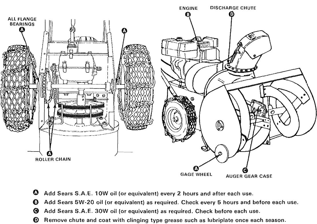
For lubrication points, frequency of lubrication and type of tubricant, see Lubrication Chart.
- Check crankcase oil level before starting engine and after each 5 hours of continuous use. Add SEARS 5W-30 motor oil or equivalent as required. Change crankcase oil after first 2 hours of operation and every 25 hours of operation thereafter, or at beginning of each season. NOTE: SEARS 5W-30 or IOW motor oil (or equivalent) are acceptable substitutes.
To Drain Oil, Proceed as Follows:
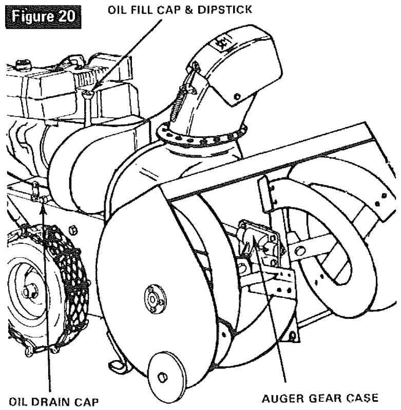
- Remove Oit fill cap and dipstick (figure 20).
- Remove oil drain cap (figure 20).
- Tip unit toward oil drain cap and drain Oit into a suitable container. NOTE: Oil will drain more freely when warm.
- Replace oil drain cap securely and fill crankcase to proper level shown on dipstick (approximately 1 1/2 pints).
2. Check auger gear case oil level before each use by removing oil level plug as shown in Lubrication Chart. Oil should be visible in hole. If oil is required, remove oil fill plug and add SEARS SAE 30 engine oil until oil begins to run out oil level hole. Replace plug and tighten securely.
3. The transmission has been factory lubricated for fife. If, for some reason, lubricant should leak out, have transmission checked by a competent repairman.
ENGINE SERVICE
Unless the operator is fully qualified to make engine adjustments and repairs, it is recommended that such work be done by technicians trained to work on snow thrower type gasoline engines.
The Engine Repair Parts section of this manual contains a list of engine replacement parts and illustrations to assist the trained technicians in making repairs and ordering proper replacement parts.
STORAGE
The snow thrower should be immediately prepared for storage at the end of the season or if the unit is to be an-used for 30 days or more.
ENGINE STORAGE
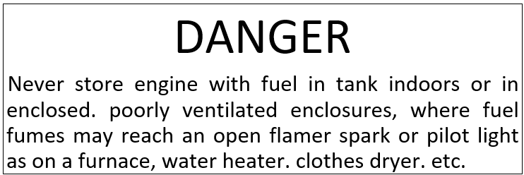
Gasoline, if permitted to stand un-used for extended periods (30 days or more), may develop gummy deposits which can adversely affect the engine carburetor and cause engine malfunction, To avoid this condition. proceed as follows:

1. Prior to shut down for 30 days or more, and for seasonal storage, drain gasoline from fuel tank

2. Run engine untit fuel tank is empty and engine stops due to lack of fuel.
3. Remove spark plug and pour one (1) ounce of engine oil through spark plug hole into cylinder. Crank engine several times to distribute oil. Replace spark plug.
4. Store unit in wheel downt operating position. If unit is stored in any other position, oil from crankcase could enter cylinder head, causing a service problem.
5. When storing unit at the end of the snow blowing season, service REWIND STARTER as follows:
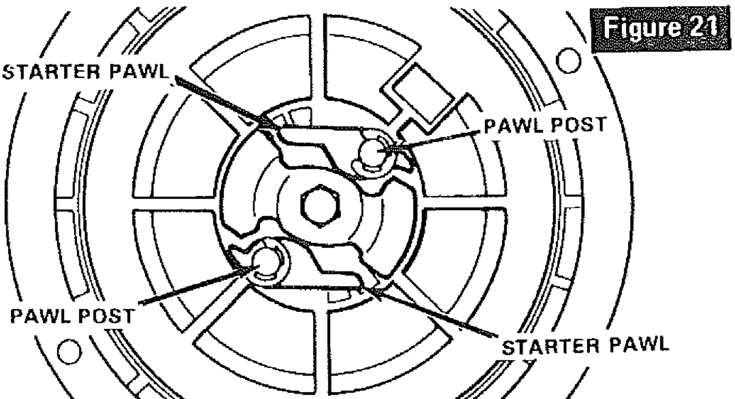
- Remove rewind starter from engine and brush away accumulation of dirt and debris from starter pawl and pawl post (figure 21).
- Apply a few drops of engine oil to each paw! post and rotate starter a few times.
- Reinstall starter on engine. Be sure the four starter retaining nuts are tightened securely.
UNIT STORAGE
- Clean the unit thoroughly; remove aEl debris and wipe the unit dry.
- Inspect the snow thrower for worn or damaged parts, tighten all loose hardware.
- Oil all points described in paragraph Lubrication.
- Store the snow thrower in a protected area and cover the unit for additional protection.
A yearly checkup or tuneup by the SEARS Service Department is a good way of insuring that your snow thrower will provide maximum performance for the next season.
LUBRICATION CHART
TROUBLESHOOTING
TROUBLE | LOOK FOR | REMEDY |
|---|---|---|
Difficult starting, Engine runs erratic | Defective spark plug | Replace defective plug. |
| Blocked fuel line or empty gas tank | Clean fuel line; check fuel supply. | |
| Review paragraph To Start Engine. | ||
Engine stalls; Loss of power; Engine runs erratic | Unit running on CHOKE | Set choke lever to RUN position. |
| Obstruction in impeller housing | Remove obstruction; clean impeller housing. Refer to Danger after Step 6 of Snow Thrower Operation paragraph in Operation section of this manual. | |
| Water in fuel system | Remove carburetor bowl to drain fuel tank. RefilE with fresh fuel | |
| CAUTION: Do not remove carburetor bowl when the engine is hot. | ||
| Excessive vibration | Loose parts; Damaged impeller | Stop engine immediately; tighten alt bolts and make all necessary repairs. If vibration continues, have the unit serviced by a competent repairman, |
| Unit fails to propel itself | Drive belt loose or defective | Replace drive belt. Refer to Drive Belt Replacement paragraph in Maintenance section of this manual. |
| Broken shear bolt | Replace shear bolt. Refer to Shear Bolt Replacement paragraph in Maintenance section of this manual. | |
| Drive roller chain defective | Replace roller chain. Refer to Roller Chain Replacement paragraph in Maintenance section of this manual. | |
| Unit drive belt loose or defective | Adjust unit drive belt; replace if defective. Refer to Drive Belt Adjustment paragraph in Adjustment section or Drive Belt Replacement paragraph in Maintenance section of this manual. | |
| Unit fails to discharge snow | Impeller drive belt loose or defective | Adjust impeller/ auger drive belt; replace if defective. Refer to Drive Belt Adjustment paragraph in Adjustment section or Drive Belt Replacement paragraph in Maintenance section of this manual. |
| Impeller/Auger control out of adjuslment | Adjust impeller/auger control cable. Refer to Impeller/ Auger Control Cable Adjustment paragraph in Adjustment section of this manual, | |
| Shear bolt broken | Replace shear bolt. Refer to Shear Bott Replacement paragraph in Maintenance section of this manual. | |
| Discharge chute clogged | Clean discharge chute and inside of auger housing. Refer to Danger after Step 6 of Snow Thrower Operation paragraph in Operation section of this manual. | |
| Foreign object lodged in auger | Remove object from auger. Refer to Danger after Step 6 of Snow Thrower Operation paragraph in Operation section of this manual, | |
| Auger gear case troubEe | Check auger gear case for broken or bound parts and for oil level. See Unit Repair Parts section of this manual for correct order of parts. | |
| Transmission trouble | Have transmission checked by competent repatrman. | |
See other models: CMXGBAM213101 CMXGSAMY426S CMXZXGA8395 CMEF901 CMMT45063
