Owner's Manual
Manual del Propietario
®
THROUGH-THE-WALLAIRCONDITIONER
ACONDIClONADODEAIREATRAVESDEPARED
Model, Modelo 580.75085
Distributed by Sears, Roebuck and Co., Hoffman Estates, IL 60179
www.sears.com
TABLE OF CONTENTS ........................2
WARRANTY ..............................................2
SAFETY .....................................................3
Important Safety Instructions ...................... 3
ELECTRICAL REQUIREMENTS .......4
INSTALLATION ........................................5
Installation Requirements ......................... 5
Installation ................................................ 6
Procedure A ............................................. 7
Procedure B ............................................. 8
Procedure C ........................................... 10
OPERATION ...........................................12
How and Why ......................................... 12
Normal Sounds ...................................... 12
Capacity and Running Time ................... 12
Features ................................................. 13
Using the Air Conditioner ....................... 13
Control Panel ......................................... 14
Remote Control ...................................... 15
MAINTENANCE .....................................17
Air Filter Cleaning ................................... 17
Air Conditioner Cleaning ........................ 17
How to Remove the Front Grille ............. 17
How to Replace the Front Grille ............. 17
TROUBLESHOOTING .........................18
Before Calling for Service ...................... 18
ESPAI_IOL ................................................20
MASTER PROTECTION
AGREEMENTS ......................................39
SERVICE NUMBERS ............ Back Cover
FULL ONE YEAR WARRANTY ON
THROUGH-THE-WALL AIR CONDITIONER
For one year from the date of purchase, when this
air conditioner is operated and maintained for
normal room cooling according to instructions in this
owner's manual, Sears will repair this air
conditioner, free of charge, if defective in material or
workmanship.
FULL FIVE-YEAR WARRANTY ON
SEALED REFRIGERATION SYSTEM
For five years from the date of purchase, when this
air conditioner is operated and maintained for
normal room cooling according to instructions in this
owner's manual, Sears will repair the sealed
refrigeration system (consisting of refrigerant,
connecting tubing, and compressor), free of charge,
if defective in material or workmanship.
WARRANTY SERVICE IS AVAILABLE BY
CONTACTING SEARS SERVICE AT
1-800-4-MY-HOME ®.
Warranty coverage applies only to air conditioners
used for non-commercial, private household
purposes.
This warranty applies only while this product is in
use in the United States.
This warranty gives you specific legal rights, and
you may also have other rights which vary from
state to state.
Distributed by Sears, Roebuck and
Co., Hoffman Estates, IL 60179
-2-
IMPORTANT SAFETY INSTRUCTIONS
The safety instructions below will tell you how to use your room air conditioner to avoid harm to yourself or
damage to your ROOM AIR CONDITIONER.
FOR YOUR SAFETY
Do not store or use gasoline or other flammable
vapors and liquids in the vicinity of this or any other
appliance. Read product labels for flammability and
other warnings.
PREVENT ACCIDENTS
To reduce the risk of fire, electrical shock, or injury
to persons when using your air conditioner, follow
basic precautions, including the following:
• Be sure the electrical service is adequate for the
model you have chosen.
• If the air conditioner is to be installed in a window,
you will probably want to clean both sides of the
glass first. If the window is a triple-track type with a
screen panel included, you may want to remove
the screen completely before installation.
• Be sure the air conditioner has been securely and
correctly installed according to the instructions in
this manual.
Save this manual and installation instructions for
possible future use in removing or reinstalling this
unit.
• Use gloves when handling the air conditioner.
Be careful to avoid cuts from sharp metal fins on
front and rear coils.
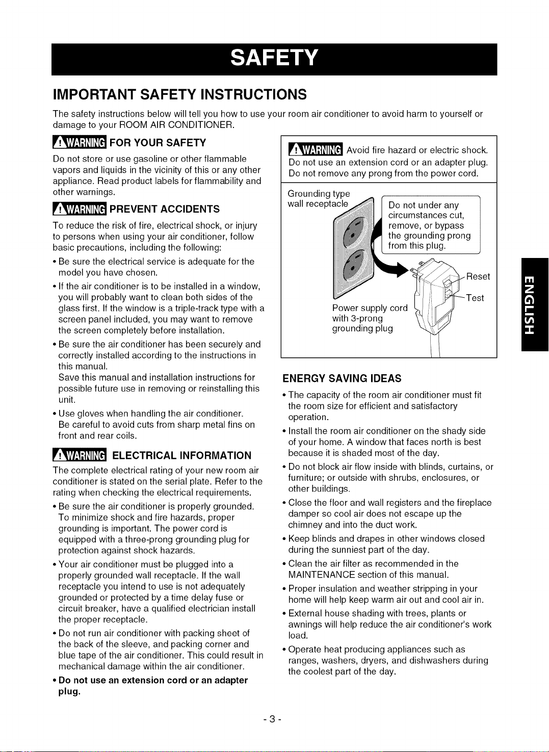
ELECTRICAL INFORMATION
The complete electrical rating of your new room air
conditioner is stated on the serial plate. Refer to the
rating when checking the electrical requirements.
• Be sure the air conditioner is properly grounded.
To minimize shock and fire hazards, proper
grounding is important. The power cord is
equipped with a three-prong grounding plug for
protection against shock hazards.
• Your air conditioner must be plugged into a
properly grounded wall receptacle. If the wall
receptacle you intend to use is not adequately
grounded or protected by a time delay fuse or
circuit breaker, have a qualified electrician install
the proper receptacle.
• Do not run air conditioner with packing sheet of
the back of the sleeve, and packing corner and
blue tape of the air conditioner. This could result in
mechanical damage within the air conditioner.
• Do not use an extension cord or an adapter
plug.
_ Avoid fire hazard or electric shock.
Do not use an extension cord or an adapter plug.
Do not remove any prong from the power cord.
Grounding type
wall receptacle
Do not under any
circumstances cut,
remove, or bypass
the grounding prong
from this plug.
Reset
Power supply cord _- , _r-_Lii!/j Test
with 3-prong
grounding plug
ENERGY SAVING IDEAS
• The capacity of the room air conditioner must fit
the room size for efficient and satisfactory
operation.
• Install the room air conditioner on the shady side
of your home. A window that faces north is best
because it is shaded most of the day.
• Do not block air flow inside with blinds, curtains, or
furniture; or outside with shrubs, enclosures, or
other buildings.
• Close the floor and wall registers and the fireplace
damper so cool air does not escape up the
chimney and into the duct work.
• Keep blinds and drapes in other windows closed
during the sunniest part of the day.
• Clean the air filter as recommended in the
MAINTENANCE section of this manual.
• Proper insulation and weather stripping in your
home will help keep warm air out and cool air in.
• External house shading with trees, plants or
awnings will help reduce the air conditioner's work
load.
• Operate heat producing appliances such as
ranges, washers, dryers, and dishwashers during
the coolest part of the day.
-3-
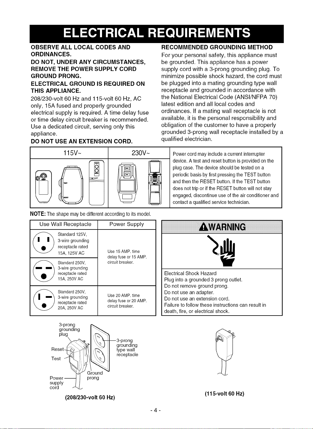
OBSERVE ALL LOCAL CODES AND
ORDINANCES.
DO NOT, UNDER ANY CIRCUMSTANCES,
REMOVE THE POWER SUPPLY CORD
GROUND PRONG.
ELECTRICAL GROUND IS REQUIRED ON
THIS APPLIANCE.
208/230-volt 60 Hz and 115-volt 60 Hz, AC
only, 15A fused and properly grounded
electrical supply is required. A time delay fuse
or time delay circuit breaker is recommended.
Use a dedicated circuit, serving only this
appliance.
DO NOT USE AN EXTENSION CORD.
RECOMMENDED GROUNDING METHOD
For your personal safety, this appliance must
be grounded. This appliance has a power
supply cord with a 3-prong grounding plug. To
minimize possible shock hazard, the cord must
be plugged into a mating grounding type wall
receptacle and grounded in accordance with
the National Electrical Code (ANSI/NFPA 70)
latest edition and all local codes and
ordinances. If a mating wall receptacle is not
available, it is the personal responsibility and
obligation of the customer to have a properly
grounded 3-prong wall receptacle installed by a
qualified electrician.
115V~
T
230V~
Power cord may include a current interrupter
device.A test and reset buttonis provided on the
plug case. Thedevice should be tested on a
periodic basis by first pressing the TEST button
andthen the RESET button. Ifthe TEST button
does not trip or if the RESET button will not stay
engaged,discontinue use of the air conditioner and
contact aqualified servicetechnician.
NOTE: The shape may be different accordingto its model.
Use Wall Receptacle Power Supply
Standard 125V,
3-wire grounding
receptacle rated
15A, 125V AC
Standard 250V,
3-wire grounding
receptacle rated
15A, 250V AC
Standard 250V,
3-wire grounding
receptacle rated
20A, 250V AC
Use 15 AMP. time
delay fuse or 15 AMP.
circuit breaker.
Use 20 AMP. time
delay fuse or 20 AMP.
circuit breaker.
Electrical Shock Hazard
Plug into a grounded 3 prong outlet.
Do not remove ground prong.
Do not use an adapter.
Do not use an extension cord.
Failure to follow these instructions can result in
death, fire, or electrical shock.
3-prong
grounding ] \_
plug I ,¢>,_'%
I',, 3-prong
Z_I _J I grounding
Reset-F4_..-_/_[l] ,_- I type wall
Test _i_t ,_ l receptacle
(208/230-volt 60 Hz)
(115-volt 60 Hz)
-4-
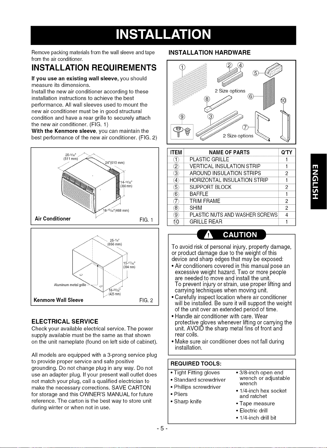
Remove packing materials from the wall sleeve and tape
from the air conditioner.
INSTALLATION REQUIREMENTS
If you use an existing wall sleeve, you should
measure its dimensions.
Install the new air conditioner according to these
installation instructions to achieve the best
performance. All wall sleeves used to mount the
new air conditioner must be in good structural
condition and have a rear grille to securely attach
the new air conditioner. (FIG. 1)
With the Kenmore sleeve, you can maintain the
best performance of the new air conditioner. (FIG. 2)
20-3/32"
(511 mm)
mm)
3/32,,
(366mm)
!8-W32':(466 mm)
Air Conditioner FIG. 1
INSTALLATION HARDWARE
2 Size options
2 Size options
ITEM NAME OF PARTS Q'TY
VERTICAL INSULATION STRIP 1
(_ AROUND INSULATION STRIPS 2
(_) HORIZONTAL INSULATION STRIP 1
SUPPORT BLOCK 2
@ BAFFLE 1
TRIM FRAME 2
@ SHIM 2
_9_ PLASTICNUTSANDWASHERSCREWS 4
GRILLE REAR 1
_ 25.7/s"
(656 mm)
17/32"
[394mm)
Aluminum metal grill_
Kenmore Wall Sleeve
(425ram)
FIG. 2
ELECTRICAL SERVICE
Check your available electrical service. The power
supply available must be the same as that shown
on the unit nameplate (found on left side of cabinet).
All models are equipped with a 3-prong service plug
to provide proper service and safe positive
grounding. Do not change plug in any way. Do not
use an adapter plug. If your present wall outlet does
not match your plug, call a qualified electrician to
make the necessary corrections. SAVE CARTON
for storage and this OWNER'S MANUAL for future
reference. The carton is the best way to store unit
during winter or when not in use.
-5-
To avoid risk of personal injury, property damage,
or product damage due to the weight of this
device and sharp edges that may be exposed:
• Air conditioners covered in this manual pose an
excessive weight hazard.Two or more people
are neededto move and install the unit.
To prevent injuryor strain, use proper lifting and
carrying techniques when moving unit.
• Carefully inspectlocation where air conditioner
will be installed. Be sure itwill supportthe weight
ofthe unitover an extended periodof time.
• Handle air conditioner with care. Wear
protective gloves whenever lifting or carrying the
unit. AVOID the sharp metal fins offront and
rear coils.
• Make sure air conditioner does notfall during
installation.
REQUIRED TOOLS:
• Tight Fitting gloves
• Standard screwdriver
• Phillips screwdriver
• Pliers
• Sharp knife
• 3/8-inch open end
wrench or adjustable
wrench
• 1/4-inch hex socket
and ratchet
• Tape measure
• Electric drill
• 1/4-inch drill bit
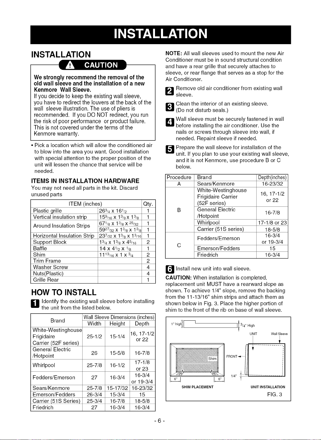
INSTALLATION
We strongly recommendthe removal of the
old wall sleeve and the installationof a new
Kenmore Wall Sleeve.
Ifyou decideto keep theexistingwallsleeve,
you haveto redirect the louvers atthe back of the
wall sleeve illustration.The use of pliers is
recommended. If you DO NOT redirect,you run
the risk of poor performance or productfailure.
This is not covered under theterms of the
Kenmorewarranty.
Pick a location which will allow the conditioned air
to blow into the area you want. Good installation
with special attention to the proper position of the
unit will lessen the chance that service will be
needed.
ITEMS IN INSTALLATION HARDWARE
You may not need all parts in the kit. Discard
unused parts
ITEM (inches)
Plastic grille
Vertical insulation strip
Around Insulation Strips
Horizontal Insulation Strip
Support Block
Baffle
Shim
Trim Frame
Washer Screw
Nuts(Plastic)
Grille Rear
263/4 X 1 61/2
159/16 X 13/8X 13/8
671/8x 13/8 X25/32
5927/32 X 13/8x 13/8
237/32x 13/8x 13/16
13/4 X 13/8 X 45/16
14 x 41/2 X 1/8
1113/16 X 1 x3/4
Qty.
1
1
1
1
1
2
1
2
2
4
4
1
HOW TO INSTALL
H dentify the existing wall sleeve before installing
the unit from the listed below.
Wall Sleeve Dimensions (inches)
Brand
White-Westinghouse
Frigidaire
Carrier (52F series)
General Electric
/Hotpoint
Width
25-1/2
26
Whirlpool 25-7/8
Fedders/Emerson 27
Sears/Kenmore 25-7/8
Emerson/Fedders 26-3/4
Carrier (51S Series) 25-3/4
Friedrich 27
Height Depth
15-1/4 16, 17-1/2
or 22
15-5/8 16-7/8
17-1/8
16-1/2
or 23
16-3/4 16-3/4
or 19-3/4
15-17/32 16-23/32
15-3/4 15
16-7/8 18-5/8
16-3/4 16-3/4
NOTE: All wall sleeves used to mount the new Air
Conditioner must be in sound structural condition
and have a rear grille that securely attaches to
sleeve, or rear flange that serves as a stop for the
Air Conditioner.
Q
O
Remove old air conditioner from existing wall
sleeve.
Clean the interior of an existing sleeve.
(Do not disturb seals.)
Wall sleeve must be securely fastened in wall
before installing the air conditioner. Use the
nails or screws through sleeve into wall, if
needed. Repaint sleeve if needed.
Prepare the wall sleeve for installation of the
unit. If you plan to use your existing wall sleeve,
and it is not Kenmore, use procedure B or C
below.
Procedure Brand Depth(inches)
A Sears/Kenmore 16-23/32
White-Westinghouse
Frigidaire Carrier 16, 17-1/2
or 22
(52F series)
B General Electric
16-7/8
/Hotpoint
Whirlpool 17-1/8 or 23
Carrier (51S series) 18-5/8
16-3/4
Fedders/Emerson
C or 19-3/4
Emerson/Fedders 15
Friedrich 16-3/4
_ Install new unit into wall sleeve.
CAUTION: When installation is completed,
replacement unit MUST have a rearward slope as
shown. To achieve 1/4" slope, remove the backing
from the 11-13/16" shim strips and attach them as
shown below in Fig. 3. Place the higher portion of
shim to the front of the rib on base of wall sleeve.
1" high[--
I___j 16_j
II 3/4" High
UNIT Wall Sleeve
SHIM PLACEMENT UNIT INSTALLATION
FIG. 3
-6-
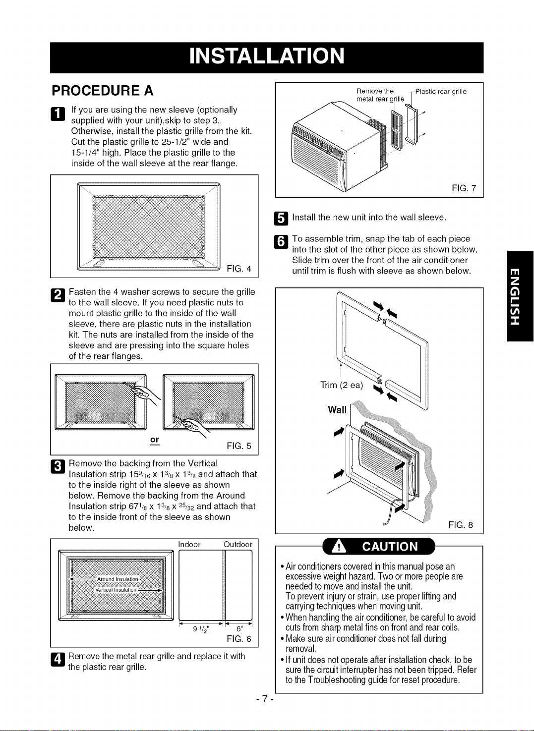
PROCEDURE A
li]l
If you are using the new sleeve (optionally
supplied with your unit),skip to step 3.
Otherwise, install the plastic grille from the kit.
Cut the plastic grille to 25-1/2" wide and
15-1/4" high. Place the plastic grille to the
inside of the wall sleeve at the rear flange.
FIG. 4
B asten the 4 washer screws to secure the grille
to the wall sleeve. If you need plastic nuts to
mount plastic grille to the inside of the wall
sleeve, there are plastic nuts in the installation
kit. The nuts are installed from the inside of the
sleeve and are pressing into the square holes
of the rear flanges.
or
FIG. 5
B Remove the backing from the Vertical
Insulation strip 159/16X 13/8x 13/8and attach that
to the inside right of the sleeve as shown
below. Remove the backing from the Around
Insulation strip 671/8x 13/8x 25/32 and attach that
to the inside front of the sleeve as shown
below.
Ir: [,]Etljii[o] I
Indoor Outdoor
9 1/2" -_ _- 6" -_
FIG. 6
L_-I_Remove the metal rear grille and replace it with
the plastic rear grille.
-7
Remove the -Plastic rear grille
metal rear gl
FIG. 7
_ Install the new unit into the wall sleeve.
To assemble trim, snap the tab of each piece
into the slot of the other piece as shown below.
Slide trim over the front of the air conditioner
until trim is flush with sleeve as shown below.
Trim (2 ea) (
Wall
-[
FIG. 8
• Airconditionerscoveredinthismanualposean
excessiveweighthazard.Twoor morepeopleare
neededtomoveandinstalltheunit.
Topreventinjuryor strain,useproperliftingand
carryingtechniqueswhenmovingunit.
•Whenhandlingtheair conditioner,becarefulto avoid
cutsfromsharpmetalfinsonfrontand rearcoils.
• Makesureairconditionerdoesnotfallduring
removal.
• If unitdoesnotoperateafterinstallationcheck,to be
surethecircuitinterrupterhasnotbeentripped.Refer
totheTroubleshootingguidefor resetprocedure.
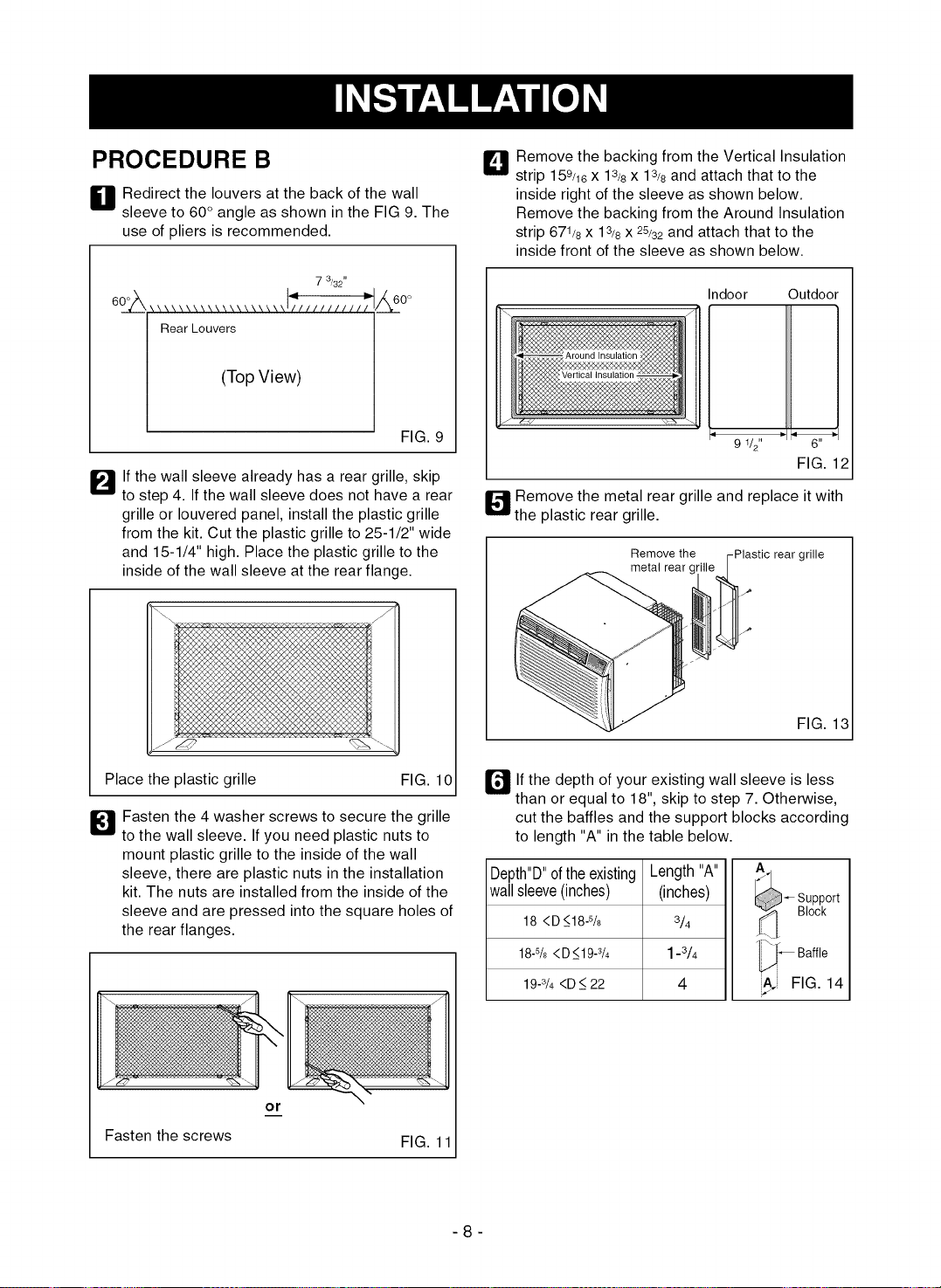
PROCEDURE B
H edirect the louvers at the back of the wall
sleeve to 60° angle as shown in the FIG 9. The
use of pliers is recommended.
7 3/32"
Rear Louvers
(Top View)
60 o
FIG. 9
_'_lf the wall sleeve already has a rear grille, skip
to step 4. If the wall sleeve does not have a rear
grille or Iouvered panel, install the plastic grille
from the kit. Cut the plastic grille to 25-1/2" wide
and 15-1/4" high. Place the plastic grille to the
inside of the wall sleeve at the rear flange.
L_ Remove the backing from the Vertical Insulation
strip 158/16X 13/8X 13/8 and attach that to the
inside right of the sleeve as shown below.
Remove the backing from the Around Insulation
strip 671/8x 13/8x 25/32 and attach that to the
inside front of the sleeve as shown below.
Place the plastic grille
_1 Fasten the 4 washer screws to secure the grille
to the wall sleeve. If you need plastic nuts to
mount plastic grille to the inside of the wall
sleeve, there are plastic nuts in the installation
kit. The nuts are installed from the inside of the
sleeve and are pressed into the square holes of
the rear flanges.
Fasten the screws
or
Vertical Insulation -
Indoor
9 1/2"
Outdoor
1
_ 6" !
FIG. 12
_ emove the metal rear grille and replace it with
the plastic rear grille.
Remove the -Plastic rear grille
metal rear (
FIG. 13
FIG. 10 [] If the depth of your existing wall sleeve is less
than or equal to 18", skip to step 7. Otherwise,
cut the baffles and the support blocks according
to length "A" in the table below.
FIG. 11
Depth"D"oftheexisting
wallsleeve(inches)
18 <D _<18-5/8
18-% <D_<19-s/4
19-3/4<D _<22
Length "A" A
(inches) _- Support
3/4 _[_ Block
1-3/4 Baffle
4 FIG. 14
-8-
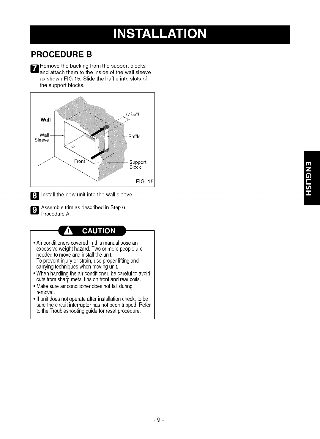
PROCEDURE B
W emove the backing from the support blocks
and attach them to the inside of the wall sleeve
as shown FIG 15. Slide the baffle into slots of
the support blocks.
_/all
_/all
_ve
7 3/32")
Block
l_ Install the new unit into the wall sleeve.
_l Assemble trim as described in Step 6,
Procedure A.
FIG. 15
pvt_ E_o] _I
•Airconditionerscoveredin thismanualposean
excessiveweighthazard.Twoor morepeopleare
neededtomoveandinstalltheunit.
Topreventinjuryor strain,useproperliftingand
carryingtechniqueswhenmovingunit.
•Whenhandlingtheairconditioner,becarefultoavoid
cutsfromsharpmetalfinsonfrontandrearcoils.
•Makesureairconditionerdoesnotfallduring
removal.
•If unitdoesnotoperateafterinstallationcheck,tobe
surethecircuitinterrupterhasnotbeentripped.Refer
totheTroubleshootingguideforresetprocedure.
-9-
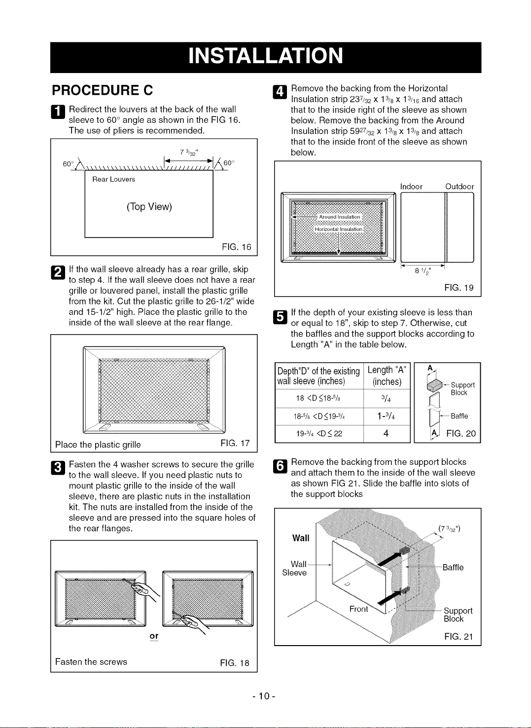
PROCEDURE C
H edirect the louvers at the back of the wall
sleeve to 60° angle as shown in the FIG 16.
The use of pliers is recommended.
7 3/32"
;--------&too
Rear Louvers
(Top View)
FIG. 16
_'_lf the wall sleeve already has a rear grille, skip
to step 4. If the wall sleeve does not have a rear
grille or Iouvered panel, install the plastic grille
from the kit. Cut the plastic grille to 26-1/2" wide
and 15-1/2" high. Place the plastic grille to the
inside of the wall sleeve at the rear flange.
Place the plastic grille FIG. 17
_1 Fasten the 4 washer screws to secure the grille
to the wall sleeve. If you need plastic nuts to
mount plastic grille to the inside of the wall
sleeve, there are plastic nuts in the installation
kit. The nuts are installed from the inside of the
sleeve and are pressed into the square holes of
the rear flanges.
or
Fasten the screws FIG. 18
_1 Remove the backing from the Horizontal
Insulation strip 237/32 X 13/8 X 13/18 and attach
that to the inside right of the sleeve as shown
below. Remove the backing from the Around
Insulation strip 5927/32 X 13/8x 13/8and attach
that to the inside front of the sleeve as shown
below.
Indoor Outdoor
8 1/2"
FIG. 19
_"_ If the depth of your existing sleeve is less than
or equal to 18", skip to step 7. Otherwise, cut
the baffles and the support blocks according to
Length "A" in the table below.
Depth"D"oftheexisting
wallsleeve(inches)
18 <D_<18-%
18-% <D_<19-3/4
19-3/4<D _<22
Length"A"
(inches)
3/4
1-3/4
4
-- upport
Block
_ Baffle
FIG. 20
r_ Remove the backing from the support blocks
and attach them to the inside of the wall sleeve
as shown FIG 21. Slide the baffle into slots of
the support blocks
Wall
Wall
Sleeve
7 3/32")
Block
FIG. 21
-10-
JV: [o ujiKo] i
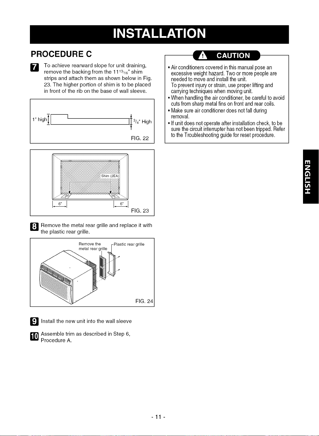
PROCEDURE C
W
To achieve rearward slope for unit draining,
remove the backing from the 1113/ld' shim
strips and attach them as shown below in Fig.
23. The higher portion of shim is to be placed
in front of the rib on the base of wall sleeve.
FIG.22
16,,i 16,,i
FIG. 23
• Airconditionerscoveredinthismanualposean
excessiveweighthazard.Twoor morepeopleare
neededto moveand installtheunit.
Topreventinjuryorstrain,useproperliftingand
carryingtechniqueswhenmovingunit.
•Whenhandlingtheairconditioner,becarefultoavoid
cutsfromsharpmetalfinsonfrontandrearcoils.
• Makesureairconditionerdoesnotfallduring
removal.
• Ifunitdoesnotoperateafterinstallationcheck,tobe
surethecircuitinterrupterhasnotbeentripped.Refer
totheTroubleshootingguideforresetprocedure.
_J Removethe metal rear grille and replace itwith
the plastic rear grille.
Remove the -Plastic rear grille
metal rear gl
FIG. 24
_'_ Install the new unit into the wall sleeve
_ ssemble trim as described in Step 6,
Procedure A.
-11 -
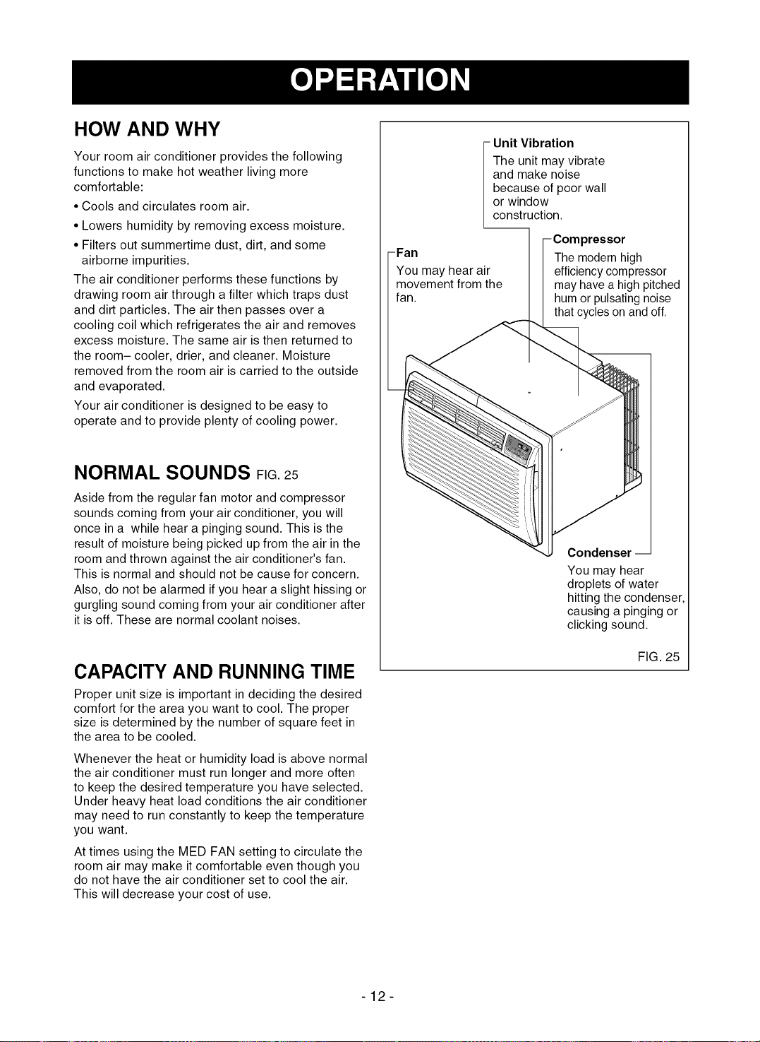
HOW AND WHY
Your room air conditioner provides the following
functions to make hot weather living more
comfortable:
• Cools and circulates room air.
• Lowers humidity by removing excess moisture.
• Filters out summertime dust, dirt, and some
airborne impurities.
The air conditioner performs these functions by
drawing room air through a filter which traps dust
and dirt particles. The air then passes over a
cooling coil which refrigerates the air and removes
excess moisture. The same air is then returned to
the room- cooler, drier, and cleaner. Moisture
removed from the room air is carried to the outside
and evaporated.
Your air conditioner is designed to be easy to
operate and to provide plenty of cooling power.
NORMAL SOUNDS FIG.25
Aside from the regular fan motor and compressor
sounds coming from your air conditioner, you will
once in a while hear a pinging sound. This is the
result of moisture being picked up from the air in the
room and thrown against the air conditioner's fan.
This is normal and should not be cause for concern.
Also, do not be alarmed if you hear a slight hissing or
gurgling sound coming from your air conditioner after
it is off. These are normal coolant noises.
CAPACITY AND RUNNING TIME
Proper unit size is important in deciding the desired
comfort for the area you want to cool. The proper
size is determined by the number of square feet in
the area to be cooled.
Whenever the heat or humidity load is above normal
the air conditioner must run longer and more often
to keep the desired temperature you have selected.
Under heavy heat load conditions the air conditioner
may need to run constantly to keep the temperature
you want.
At times using the MED FAN setting to circulate the
room air may make it comfortable even though you
do not have the air conditioner set to cool the air.
This will decrease your cost of use.
-Fan
i nit Vibration
The unit may vibrate
and make noise
because of poor wall
or window
construction.
- Compressor
The modern high
You may hear air efficiency compressor
movement from the may have a high pitched
fan. hum or pulsating noise
that cycles on and off.
Condenser --
You may hear
droplets of water
hitting the condenser,
causing a pinging or
clicking sound.
FIG. 25
-12-
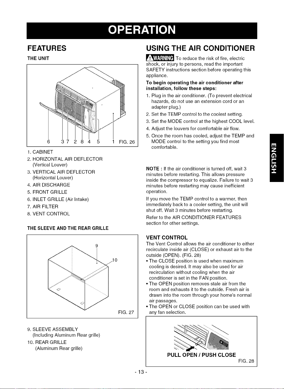
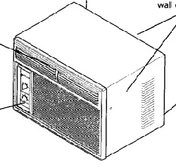
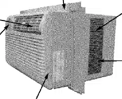
FEATURES
THE UNIT
6 3 7 2 8 4 5 1 FIG. 26
1. CABINET
2. HORIZONTAL AIR DEFLECTOR
(Vertical Louver)
3. VERTICAL AIR DEFLECTOR
(Horizontal Louver)
4. AIR DISCHARGE
5. FRONT GRILLE
6. INLET GRILLE (Air Intake)
7. AIR FILTER
8. VENT CONTROL
THE SLEEVE AND THE REAR GRILLE
FIG. 27
USING THE AIR CONDITIONER
_To reduce the risk of fire, electric
shock, or injury to persons, read the important
SAFETY instructions section before operating this
appliance.
To begin operating the air conditioner after
installation, follow these steps:
1. Plug in the air conditioner. (To prevent electrical
hazards, do not use an extension cord or an
adapter plug.)
2. Set the TEMP control to the coolest setting.
3. Set the MODE control at the highest COOL level.
4. Adjust the louvers for comfortable air flow.
5. Once the room has cooled, adjust the TEMP and
MODE control to the setting you find most
comfortable.
NOTE : If the air conditioner is turned off, wait 3
minutes before restarting. This allows pressure
inside the compressor to equalize. Failure to wait 3
minutes before restarting may cause inefficient
operation.
If you move the TEMP control to a warmer, then
immediately back to a cooler setting, the unit will
shut off. Wait 3 minutes before restarting.
Refer to the AIR CONDITIONER FEATURES
section for other settings.
VENT CONTROL
The Vent Control allows the air conditioner to either
recirculate inside air (CLOSE) or exhaust air to the
outside (OPEN). (FIG. 28)
• The CLOSE position is used when maximum
cooling is desired. It may also be used for air
recirculation without cooling when the air
conditioner is set in the FAN position.
• The OPEN position removes stale air from the
room and exhausts it to the outside. Fresh air is
drawn into the room through your home's normal
air passages.
• The OPEN or CLOSE position can be used with
any fan selection.
9. SLEEVE ASSEMBLY
(Including Aluminum Rear grille)
10. REAR GRILLE
(Aluminum Rear grille)
PULL OPEN / PUSH CLOSE
FIG. 28
-13-
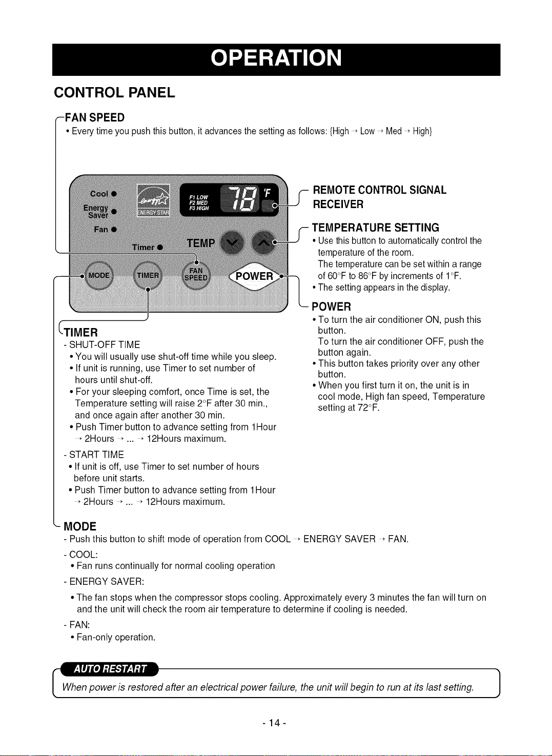
CONTROL PANEL
-FAN SPEED
• Every time you push this button, it advances the setting as follows: {High _ Low_ Med_ High}
(--TIMER
- SHUT-OFF TIME
• You will usually use shut-off time while you sleep.
• If unit is running, use Timer to set number of
hours until shut-off.
• For your sleeping comfort, once Time is set, the
Temperature setting will raise 2°F after 30 min.,
and once again after another 30 min.
• Push Timer button to advance setting from 1Hour
2Hours , ... , 12Hours maximum.
- START TIME
• If unit is off, use Timer to set number of hours
before unit starts.
• Push Timer button to advance setting from 1Hour
2Hours , ... , 12Hours maximum.
REMOTE CONTROL SIGNAL
RECEIVER
TEMPERATURE SETTING
• Use this button to automatically control the
temperature of the room.
The temperature can be set within a range
of 60°F to 86°F by increments of I°F.
• The setting appears in the display.
POWER
• To turn the air conditioner ON, push this
button.
To turn the air conditioner OFF, push the
button again.
• This button takes priority over any other
button.
• When you first turn it on, the unit is in
cool mode, High fan speed, Temperature
setting at 72°F.
MODE
- Push this button to shift mode of operation from COOL _ENERGY SAVER _FAN.
- COOL:
• Fan runs continually for normal cooling operation
- ENERGY SAVER:
• The fan stops when the compressor stops cooling. Approximately every 3 minutes the fan will turn on
and the unit will check the room air temperature to determine if cooling is needed.
- FAN:
• Fan-only operation.
Whenpower is restored after an electrical power failure, the unit will begin to run at its last setting.
-14-
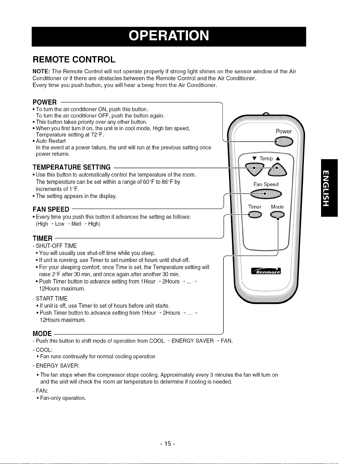
REMOTE CONTROL
NOTE: The Remote Control will not operate properly if strong light shines on the sensor window of the Air
Conditioner or if there are obstacles between the Remote Control and the Air Conditioner.
Every time you push button, you will hear a beep from the Air Conditioner.
POWER
• To turn the air conditioner ON, push this button. |
To turn the air conditioner OFF, push the button again.
/
• This button takes priority over any other button.
• When you first turn it on, the unit is in cool mode, High fan speed,
Temperature setting at 72°F.
• Auto Restart
In the event at a power failure, the unit will run at the previous setting once
power returns.
TEMPERATURE SETTING
• Use this button to automatically control the temperature of the room.
Y
Power
• Temp •
The temperature can be set within a range of 60°F to 86°F by
increments of I°F.
• The setting appears in the display.
FAN SPEED
• Every time you push this button it advances the setting as follows:
(High _Low _Ned _ High)
TIMER
- SHUT-OFF TIME
• You will usually use shut-off time while you sleep.
• If unit is running, use Timer to set number of hours until shut-off.
Fan Speed
Timer Mode
!
• For your sleeping comfort, once Time is set, the Temperature setting will
raise 2°F after 30 min, and once again after another 30 min.
• Push Timer button to advance setting from 1Hour , 2Hours , ...
12Hours maximum.
- START TIME
• If unit is off, use Timer to set of hours before unit starts.
• Push Timer button to advance setting from 1Hour , 2Hours , ...
12Hours maximum.
MODE
- Push this button to shift mode of operation from COOL , ENERGY SAVER _ FAN.
- COOL:
• Fan runs continually for normal cooling operation
- ENERGY SAVER:
• The fan stops when the compressor stops cooling. Approximately every 3 minutes the fan will turn on
and the unit will check the room air temperature to determine if cooling is needed.
- FAN:
• Fan-only operation.
-15-
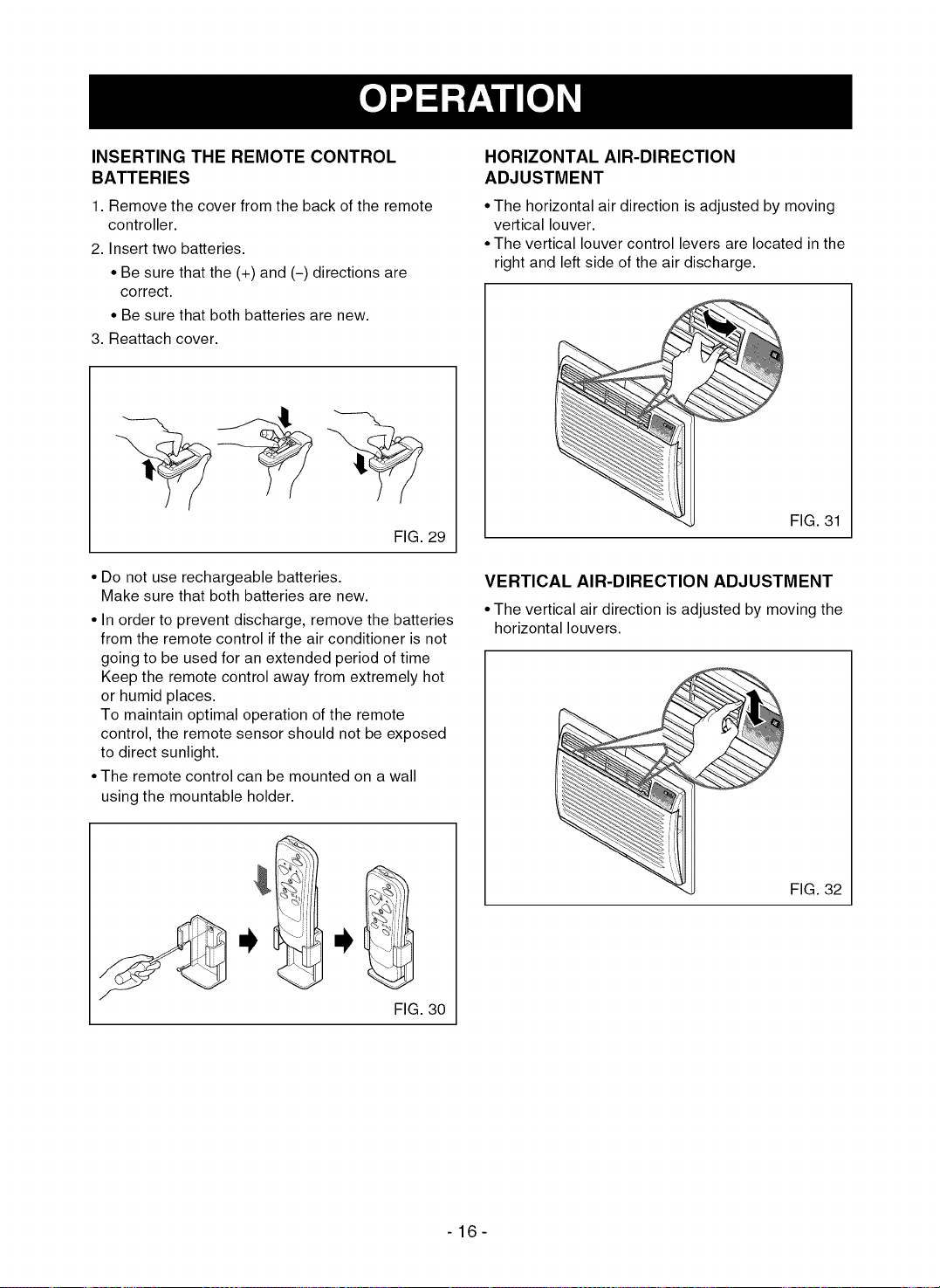
INSERTING THE REMOTE CONTROL
BATTERIES
1. Remove the cover from the back of the remote
controller.
2. Insert two batteries.
• Be sure that the (+) and (-) directions are
correct.
• Be sure that both batteries are new.
3. Reattach cover.
FIG. 29
• Do not use rechargeable batteries.
Make sure that both batteries are new.
• In order to prevent discharge, remove the batteries
from the remote control if the air conditioner is not
going to be used for an extended period of time
Keep the remote control away from extremely hot
or humid places.
To maintain optimal operation of the remote
control, the remote sensor should not be exposed
to direct sunlight.
• The remote control can be mounted on a wall
using the mountable holder.
HORIZONTAL AIR-DIRECTION
ADJUSTMENT
• The horizontal air direction is adjusted by moving
vertical louver.
• The vertical louver control levers are located in the
right and left side of the air discharge.
FIG. 31
VERTICAL AIR-DIRECTION ADJUSTMENT
• The vertical air direction is adjusted by moving the
horizontal louvers.
FIG. 30
FIG. 32
-16-
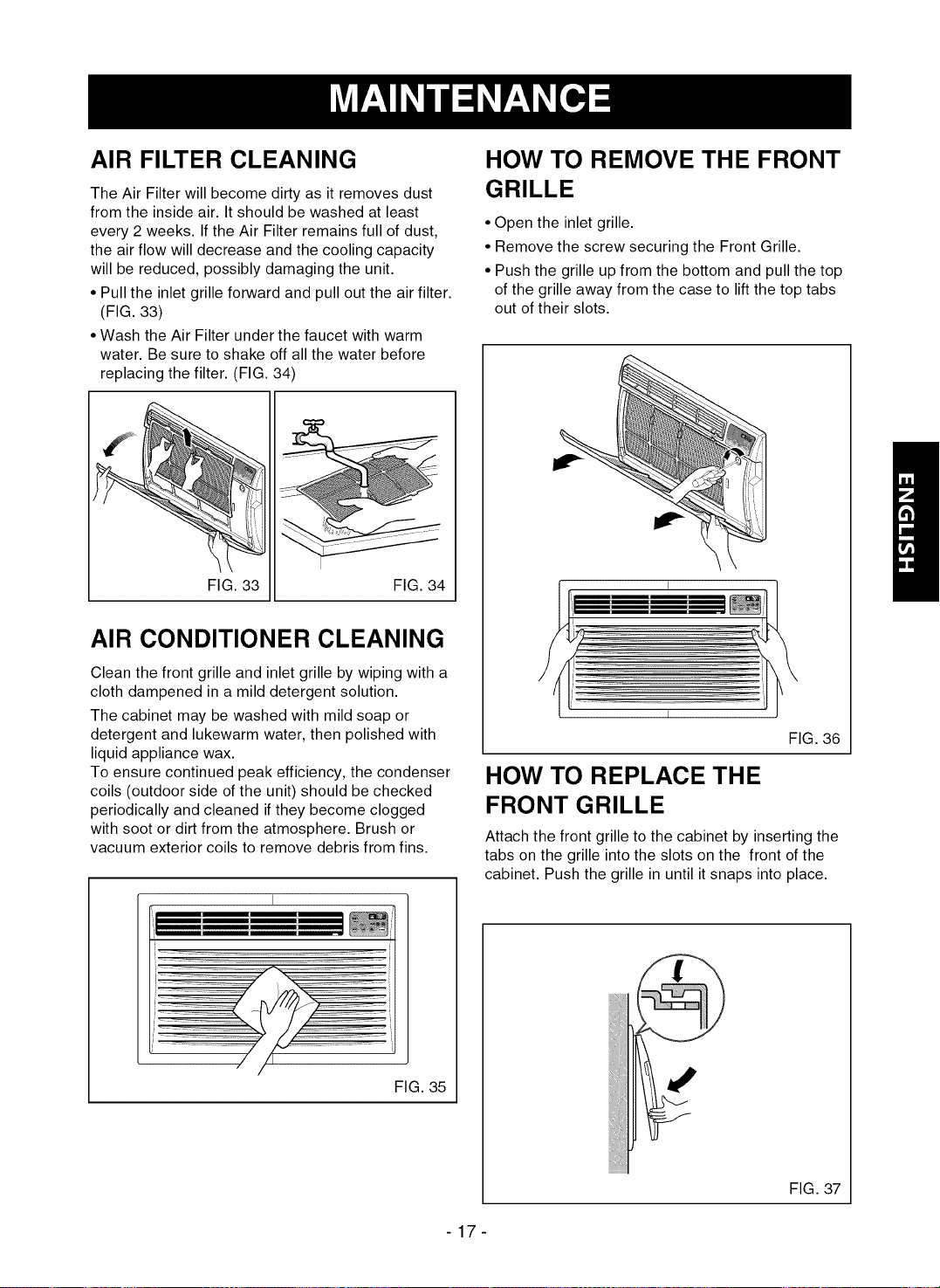
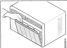
AIR FILTER CLEANING
The Air Filter will become dirty as it removes dust
from the inside air. It should be washed at least
every 2 weeks. If the Air Filter remains full of dust,
the air flow will decrease and the cooling capacity
will be reduced, possibly damaging the unit.
• Pull the inlet grille forward and pull out the air filter.
(FIG. 33)
• Wash the Air Filter under the faucet with warm
water. Be sure to shake off all the water before
replacing the filter. (FIG. 34)
FIG. 33 FIG. 34
AIR CONDITIONER CLEANING
Clean the front grille and inlet grille by wiping with a
cloth dampened in a mild detergent solution.
The cabinet may be washed with mild soap or
detergent and lukewarm water, then polished with
liquid appliance wax.
To ensure continued peak efficiency, the condenser
coils (outdoor side of the unit) should be checked
periodically and cleaned if they become clogged
with soot or dirt from the atmosphere. Brush or
vacuum exterior coils to remove debris from fins.
I
"-- I
j _;
" I/KN ......
FIG. 35
HOW TO REMOVE THE FRONT
GRILLE
• Open the inlet grille.
• Remove the screw securing the Front Grille.
• Push the grille up from the bottom and pull the top
of the grille away from the case to lift the top tabs
out of their slots.
I
FIG. 36
HOW TO REPLACE THE
FRONT GRILLE
Attach the front grille to the cabinet by inserting the
tabs on the grille into the slots on the front of the
cabinet. Push the grille in until it snaps into place.
FIG. 37
-17-
BEFORE CALLING FOR SERVICE
Check the following list to be sure a service call is really necessary. A quick reference to this manual may
help you avoid an unneeded service call.
THE AIR CONDITIONER WILL NOT OPERATE
Check if... Then...
The CurrentinterrupterDeviceistripped.
Wall plug disconnected.
House fuse blown or circuit breaker tripped.
Power is OFF.
Unit was turned offand then on too quickly.
TEMP Control set warmer than room temperature.
Press the RESET button located on the power cord plug.
If the RESET button will not stay engaged, discontinue use of the
air conditioner and contact a qualified service technician.
Push plug firmly into wall outlet.
Replace fuse with time delay type or reset circuit breaker.
Push the power button.
Set unit offand wait 3 minutes before restarting.
Set TEMP Control to a lower number.
AIR FROM UNIT DOES NOT FEEL COLD ENOUGH.
Check if... Then...
FANSPEEDsetat LOW. PushFANSPEEDbuttontosetatHI.
TEMPControlsettoowarm. SetTEMPControltoalowertemperature.
Roomtemperaturebelow70°F(21°C). Coolingmaynotoccuruntilroomtemperaturerisesabove70°F (21°C).
Temperaturesensingtubetouchingevaporatorcoil, Straightentubeawayfromevaporatorcoil.
locatedbehindfrontgrille.
THEAIRCONDITIONERCOOLING,BUTROOMISTOOWARM- ICEFORMINGONCOOLINGCOILBEHINDINLETGRILLE.
Check if... Then...
Outdoortemperaturebelow70°F(21°C). To defrostthecoil,settheMODEtoFAN,FANspeedtoHigh.
Airfiltermaybedirty. Cleanairfilter.RefertoMaintenancesectionofowner'smanual.
Todefrostthecoil,settheMODEtoCool,Fanspeedtohigh,andthe
TEMPControlsettoolow. Tempcontroltoa highertemperature.
THEAIRCONDITIONERCOOLING,BUTROOMISTOOWARM
Check if... Then...
Dirtyairfilter- airrestricted. Cleanairfilter.RefertoMaintenancesectionofowner'smanual.
TEMPControlsettoowarm. SetTEMPControltoalowertemperature.
Frontofunitisblockedbydrapes,blinds,furniture,etc. Clearblockageinfrontofunit.
Airdistributionisrestricted.
Doors,windows,registers,etc.open.Coldairescapes. Closedoors,windows,registers,etc.
Unitrecentlyturnedoninhotroom. Allowadditionaltimetoremovestoredheatfromwalls,ceiling,floor,andfurniture.
THE AIR CONDITIONER TURNS ON AND OFF RAPIDLY.
Check if... Then...
Outsidetemperatureisextremelyhot. SetFANSPEEDonHItominimizethecoolingload.
Unitissettoenergysavermode. Approximatelyevery3minutesthefanwillturnonandthe unitwillcheck
theroomairtemperaturetodetermineifcoolingisneeded.Thisis
normalenergysavermodeoperation.
NOISE WHEN UNIT IS COOLING.
Check if... Then...
Soundoffanhittingwater-from themoistureremovalsystem. Thisisnormalwhenhumidityishigh.Closedoors,windows,andregisters.
Windowvibration- poorinstallation. Referto nsta aton nstructonsorcheckwth nsta er.
WATER DRIPPING INSIDE ROOM WHEN UNIT IS COOLING.
Check if... Then...
Theairconditionerisimproperlyinstalled. Tiltairconditionerslightlytotheoutsidetoallowwaterdrainage.Referto
installationinstructionsorcheckwithinstaller.
WATER DRIPPING OUTSIDE WHEN UNIT IS COOLING.
Check if... Then...
Theunitisremovinglargequantitiesofmoisture Thisisnormalduringexcessivelyhumiddays.
fromhumidroom.
-18-

-19-
CONTENIDO ...........................................20
GARANTIA ..............................................20
SEGURIDAD ..........................................21
Instrucciones importantes de seguridad ...21
REQUlSlTOS ELECTRICOS .............22
INSTALAClON ........................................23
Requisitos de instalaci6n ....................... 23
Instalaci6n .............................................. 24
Procedimiento A ..................................... 25
Procedimiento B..................................... 26
Procedimiento C ..................................... 28
FUNCIONAMIENTO ............................30
C6mo y por qu_ ...................................... 30
Ruidos normales .................................... 30
Capacidad y tiempo de ejecuci6n .......... 30
Caracteristicas ....................................... 31
Uso del aire acondicionado .................... 31
Panel de control ..................................... 32
Mando a distancia .................................. 33
MANTENIMIENTO ................................35
Limpieza del filtro de aire ....................... 35
Limpieza del aire acondicionado ............ 35
C6mo desmontar la rejilla frontal ........... 35
C6mo sustituir la rejilla frontal ................ 35
SOLUClON DE AVERIAS .................. 36
Antes de solicitar el servicio
de reparaci6n ......................................... 36
ACUERDOS PRINCIPALES DE
PROTECCION ........................................39
NUMEROS DE SERVICl0 .........Cubiertatrasera
GARANTIA COMPLETA DE UN ANO EN
EL AIRE ACONDICIONADO A TRAVES
DE PARED
Durante un afio a partir de la fecha de compra,
cuando este aire acondicionado funcione y se
mantenga para el enfriamiento normal seg0n las
instrucciones en el manual del propietario, Sears
reparar& este aire acondicionado, gratuitamente, si
existen defectos en el material o la mano de obra.
GARANTIA COMPLETA DE CINCO
ANOS EN EL SISTEMA SELLADO DE
REFRIGERACION
Durante cinco afios a partir de la fecha de compra,
cuando este aire acondicionado funcione y se
mantenga para el enfriamiento normal seg0n las
instrucciones en el manual del propietario, Sears
reparar& el sistema de sellado refrigeraci6n (que
consiste en refrigerante, tuberias de conexi6n, y
compresor), gratuitamente, si existen defectos en el
material o la mano de obra.
EL SERVIClO DE GARANT|A ESTA
DISPONIBLE ENTRANDO EN CONTACTO
CON EL SERVlClO DE SEARS EN EL
1-800-4-MY-HOME ®.
La cobertura de la garantia se aplica t_nicamente a
los aires acondicionaos utilizados con prop6sitos no
comerciales, dom_sticos privados.
Esta garantia se aplica t_nicamente mientras este
producto se encuentre en uso en los Estados
Unidos.
Esta garantia le da derechos legales especMcos, y
tambi_n puede tener otros derechos que varien de
estado a estado.
Distributed by Sears, Roebuck and
Co., Hoffman Estates, IL 60179
- 20 -
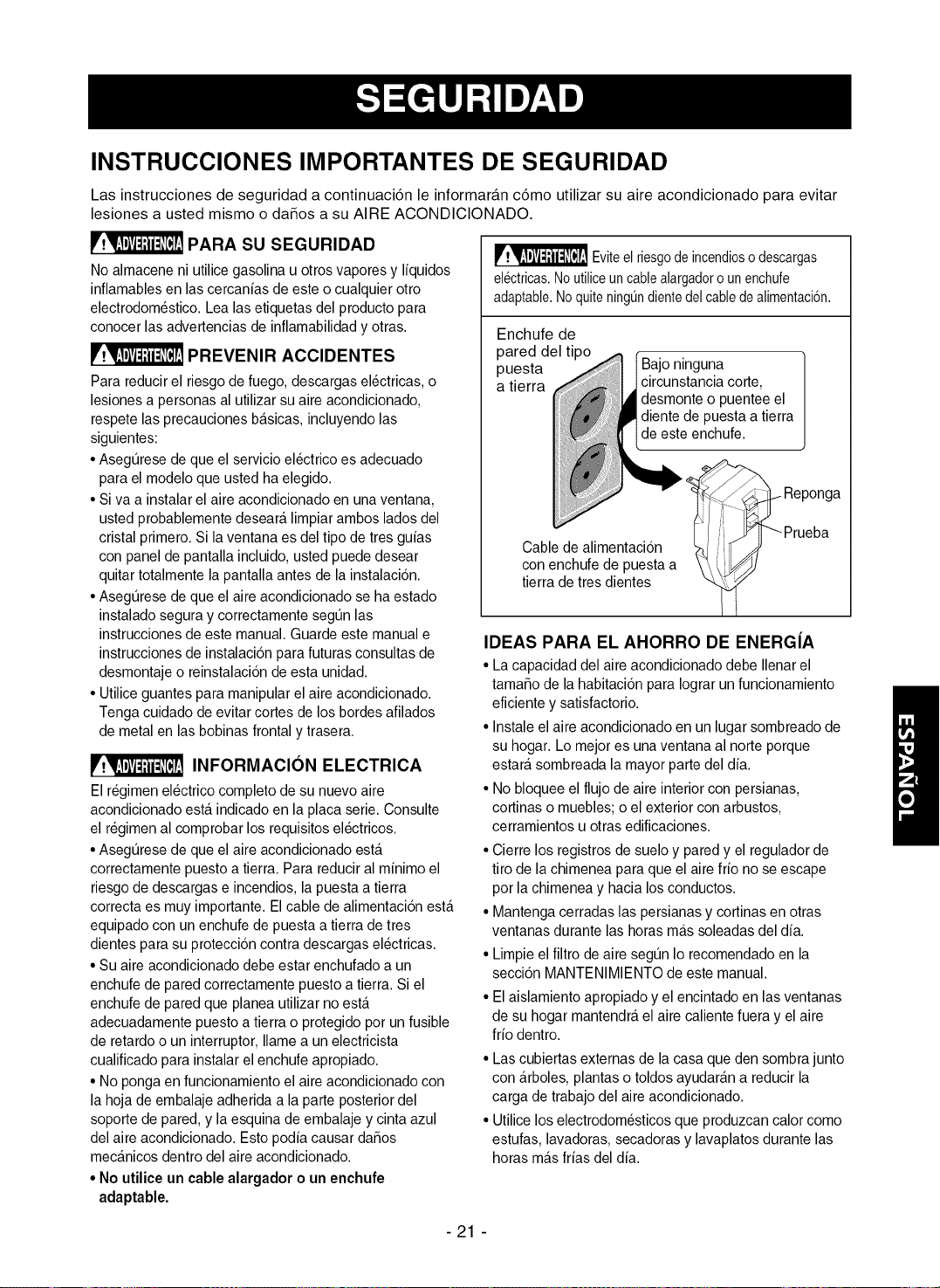
INSTRUCCIONES IMPORTANTES DE SEGURIDAD
Las instrucciones de seguridad a continuaci6n le informar_.n c6mo utilizar su aire acondicionado para evitar
lesiones a usted mismo o da_os a su AIRE ACONDIClONADO.
r,._..Im_v_|i:ll[_r:!PARA SU SEGURIDAD
No almacene ni utilice gasolina u otros vapores y liquidos
inflamables en lascercanias de este ocualquier otro
electrodomestico. Lea las etiquetas del producto para
conocer las advertencias de inflamabilidad y otras.
PREVENIR ACCIDENTES
Para reducir el riesgo de fuego, descargas electricas, o
lesionesa personas al utilizar su aire acondicionado,
respete las precauciones basicas, incluyendo las
siguientes:
• Asegt_resede que el servicio electrico es adecuado
para el modelo que usted ha elegido.
• Siva a instalar el aire acondicionado en unaventana,
usted probablemente deseara limpiar ambos lados del
cristal primero. Si laventana es del tipo de tres guias
con panel de pantalla incluido, usted puede desear
quitar totalmente la pantalla antes de la instalacion.
• Asegurese de que el aire acondicionado se ha estado
instalado segura y correctamente segun las
instrucciones de este manual. Guarde este manual e
instrucciones de instalacion para futuras consultas de
desmontaje o reinstalacion de esta unidad.
• Utilice guantes para manipular el aire acondicionado.
Tenga cuidado de evitar cortes de los bordes afilados
de metal en las bobinas frontal y trasera.
INFORMACION ELECTRICA
El regimen electrico completo de su nuevo aire
acondicionado esta indicado en la placa serie. Consulte
el regimen al comprobar los requisitos electricos.
• Asegurese de que el aire acondicionado esta
correctamente puesto a tierra. Para reducir al minimo el
riesgo de descargas e incendios, la puesta a tierra
correcta es muy importante. Elcable de alimentacion esta
equipado con un enchufede puesta a tierra de tres
dientes para su proteccion contra descargas electricas.
• Su aire acondicionado debe estar enchufado a un
enchufe de pared correctamente puesto a tierra. Si el
enchufe de pared que planea utilizar no esta
adecuadamente puesto a tierra o protegido pot un fusible
de retardo o un interruptor, Ilame a un electricista
cualificado para instalar el enchufe apropiado.
• No ponga en funcionamiento el aireacondicionado con
la hoja de embalaje adherida a la parte posterior del
soporte de pared, y la esquina de embalaje y cinta azul
del aire acondicionado. Esto podia causar daSos
mecanicos dentro del aire acondicionado.
• No utilice un cable alargador o un enchufe
adaptable.
_ Eviteel riesgodeincendioso descargas
electricas.Noutiliceuncablealargadorounenchufe
adaptable.Noquiteningt]ndientedelcabledealimentaci6n.
Enchufe de
pared del tipo c
puesta _I ] Bajo ninguna
circunstancia corte,
a tierra !_ |desmonte o puentee el
i _diente de puesta a tierra
_Ide este<_enchufe. Reponga
Cable de alimentacion I-n/ iil_J _Prueba
con enchufe de puesta a
tierra de tres dientes
IDEAS PARA EL AHORRO DE ENERG|A
• La capacidad del aire acondicionado debe Ilenarel
tama_o de la habitacion para Iograrun funcionamiento
eficiente y satisfactorio.
• Instale el aire acondicionado en un lugar sombreado de
su hogar. Lo mejor es una ventana al norteporque
estara sombreada la mayor parte del dia.
• No bloquee el flujo de aire interior con persianas,
cortinas o muebles; o el exterior con arbustos,
cerramientos u otras edificaciones.
• Cierre los registros de suelo y pared y el regulador de
tiro de la chimenea para queel aire frio no se escape
pot lachimenea y hacia losconductos.
• Mantenga cerradas laspersianas y cortinas en otras
ventanas durante lashoras mas soleadas del dia.
• Limpie el filtro de aire segun Io recomendado en la
seccion MANTENIMIENTO de este manual.
• El aislamiento apropiado y el encintado en las ventanas
de su hogar mantendra el aire caliente fuera y el aire
frio dentro.
• Las cubiertas externas de la casa que den sombra junto
con arboles, plantas o toldos ayudaran a reducir la
carga de trabajo del aire acondicionado.
• Utilice los electrodomesticos que produzcan calor como
estufas, lavadoras, secadoras y lavaplatos durante las
horas mas frias del dia.
-21 -
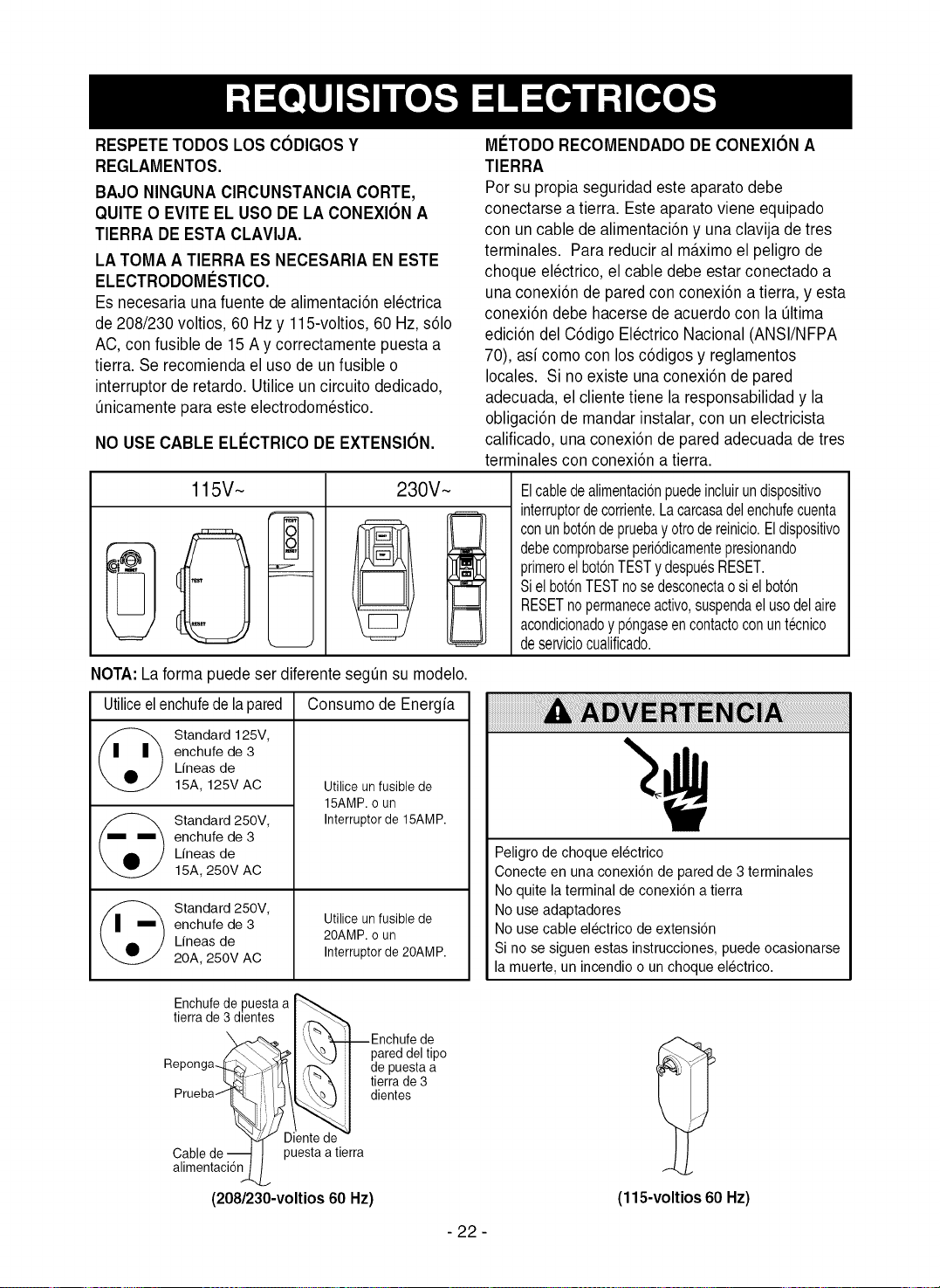
i
RESPETE TODOS LOS CODIGOS Y
REGLAMENTOS.
BAJO NINGUNA CIRCUNSTANCIA CORTE,
QUITE O EVITE EL USODE LA CONEXION A
TIERRA DE ESTA CLAVIJA.
LA TOMA A TIERRA ES NECESARIA EN ESTE
ELECTRODOMI_STICO.
Es necesaria una fuente de alimentaci6n electrica
de 208/230 voltios, 60 Hz y 115-voltios, 60 Hz,s61o
AC, confusible de 15 A y correctamente puesta a
tierra. Se recomienda el uso de un fusible o
interruptor de retardo. Utilice un circuito dedicado,
0nicamente para este electrodomestico.
NO USECABLE ELI_CTRICODEEXTENSION.
MCTODO RECOMENDADO DECONEXION A
TIERRA
Por su propia seguridad este aparato debe
conectarse a tierra. Este aparatoviene equipado
con un cable de alimentaci6n y una clavija de tres
terminales. Para reducir al m&ximoel peligro de
choque electrico, el cable debe estar conectado a
una conexi6n de pared con conexi6n a tierra, y esta
conexi6n debe hacerse de acuerdocon la 01tima
edici6n del C6digo Electrico Nacional (ANSI/NFPA
70), asi como con losc6digos y reglamentos
locales. Si no existe una conexi6n de pared
adecuada, el cliente tiene la responsabilidad y la
obligaci6n de mandar instalar, con un electricista
calificado, una conexi6n de pared adecuada de tres
terminales con conexi6n a tierra.
115V~ 230V~
Elcabledealimentaci6npuedeincluirundispositivo
interruptordecorriente.Lacarcasadelenchufecuenta
conunbot6ndepruebayotrodereinicio.Eldispositivo
debecomprobarseperi6dicamentepresionando
primeroelbotonTESTydespuesRESET.
Sielbot6nTESTnosedesconectaosielboton
RESETnopermaneceactivo,suspendaelusodelaire
acondicionadoyp6ngaseencontactoconuntecnico
deserviciocualificado.
NOTA:La forma puede ser diferente segun su modelo.
Utiliceelenchufede lapared Consumode Energfa
Standard 125V,
enchufe de 3
Lfneas de
15A, 125V AC
Standard 250V,
enchufe de 3
Lfneas de
15A, 250V AC
Standard 250V,
enchufe de 3
Lfneas de
20A, 250V AC
Utilice unfusible de
15AMP.o un
Interrupter de 15AMP.
Utilice unfusible de
20AMP. o un
Interruptor de 20AMP.
Peligro de choque electrico
Conecte en una conexi6n de paredde 3 terminales
No quite la terminal de conexi6n atierra
No use adaptadores
No use cable electrico de extensi6n
Si no se siguen estas instrucciones, puede ocasionarse
la muerte, un incendio o un choque electrico.
Enchufede puesta a
tierra de 3 dientes I _"_
',,V '- Enchufede
/_'_1 \_ } I pareddeltipo
ReP°°ga4- I4"& I de puesta a
'_bkll.\"\ / tierrade3
Prueba_,/_/_ l dientes
Diente de -
Cable de-_ D_esta atierra
alimentacidn_
(208/230-voltios60 Hz) (115-voltios 60 Hz)
- 22 -
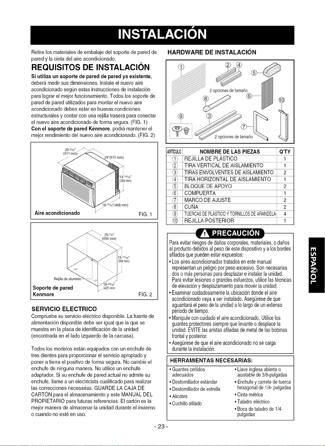
Retirelos rnateriales de ernbalaje del soporte de paredde
paredy la cinta del aire acondicionado.
REQUISITOS DE INSTALACION
Si utiliza un soporte de pared de pared ya existente,
debera medir susdimensiones. Instale el nuevo aire
acondicionado segt]n estas instrucciones de instalaci6n
para Iograrel mejor funcionamiento. Todoslos soporte de
paredde pared utilizados )ara montar el nuevoaire
acondicionado deben estar en buenascondiciones
estructurales y contar con una rejilla trasera para conectar
el nuevo aire acondicionado de forma segura. (FIG. 1)
Con el soporte de pared Kenmore, podra rnantenerel
mejor rendimiento del nuevo aire acondicionado. (FIG. 2)
HARDWARE DE INSTALACION
2opcionesdetama5o
2 opcionesdetamaiSo
20-3/32"
(511 ram)
mm)
3/32,,
(366mm)
[8-W32"(466 mm)
Aire acondicionado FIG. 1
ARTiCUL0 NOMBRE DE LAS PIEZAS Q'TY
TIRA VERTICAL DE AISLAMIENTO 1
TIRASENVOLVENTESDEAISLAMIENTO 2
(_0 TIRA HORIZONTAL DE AISLAMIENTO 1
BLOQUE DEAPOYO 2
@ COMPUERTA 1
MARCO DE AJUSTE 2
@ CUI_A 2
_9_ TUERCASDEPLASTICOYTORNILLOSDEARANDELA4
REJILLA POSTERIOR 1
25-7/8"
(656 mm)
Rejilla de alumink
6=23/32"
Soporte de pared (425ram)
Kenmore FIG. 2
SERVICIO ELECTRICO
Cornpruebe su servicio electrico disponible. La fuente de
alirnentacion disponible debe set igual que la que se
rnuestraen la placa de identificacion de la unidad
(encontrada en el lado izquierdo de la carcasa).
Todos los rnodelos estan equipados con un enchufe de
tres dientes para proporcionar el servicio apropiado y
ponera tierra el positivo de forrna segura. No carnbie el
enchufe de ninguna rnanera. No utilice un enchufe
adaptador. Si su enchufe de pared actual no adrnite su
enchufe, Ilarnea un electricista cualificado para realizar
las correcciones necesarias. GUARDE LA CAJA DE
CARTON para el alrnacenarnientoy este MANUAL DEL
PROPIETARIO para futuras referencias. El cart6n es la
mejor manera de almacenar la unidad durante el invierno
o cuando no este en uso.
Paraevitarriesgosdeda_oscorporales,materiales,oda_os
alproductodebidosalpesodeestedispositivoyalosbordes
afiladosquepuedenestarexpuestos:
•Losairesacondicionadostratadosenestemanual
representanunpeligroporpesoexcesivo.Sonnecesarias
doso maspersonasparadesplazareinstalarlaunidad.
Paraevitarlesioneso grandesesfuerzos,utilicelastecnicas
deelevaci6nydesplazamientoparamoverlaunidad.
•Examinarcuidadosamentelaubicaci6ndondeelaire
acondicionadovayaasetinstalado.Asegt_resedeque
aguantaraelpesodelaunidadaIolargodeunextenso
perbdodetiempo.
•Manipuleconcuidadoelaireacondicionado.Utilicelos
guantesprotectoressiemprequelevanteodesplacela
unidad.EVlTElasaristasafiladasdemetaldelasbobinas
frontalyposterior.
•Asegdiresedequeelaireacondicionadonosecaiga
durantelainstalaci6n.
HERRAMIENTAS NECESARIAS:
• Guantesce_idos
adecuados
• Destomilladorestandar
• Destornilladordeestrella
• Alicates
• Cuchilloafilado
• Llaveinglesaabiertao
ajustablede3/8-pulgadas
• Enchufeycarretedetuerca
hexagonalde1/4-pulgadas
• Cintametrica
• Taladroelectrico
• Bocadetaladrode 1/4-
pulgadas
- 23 -
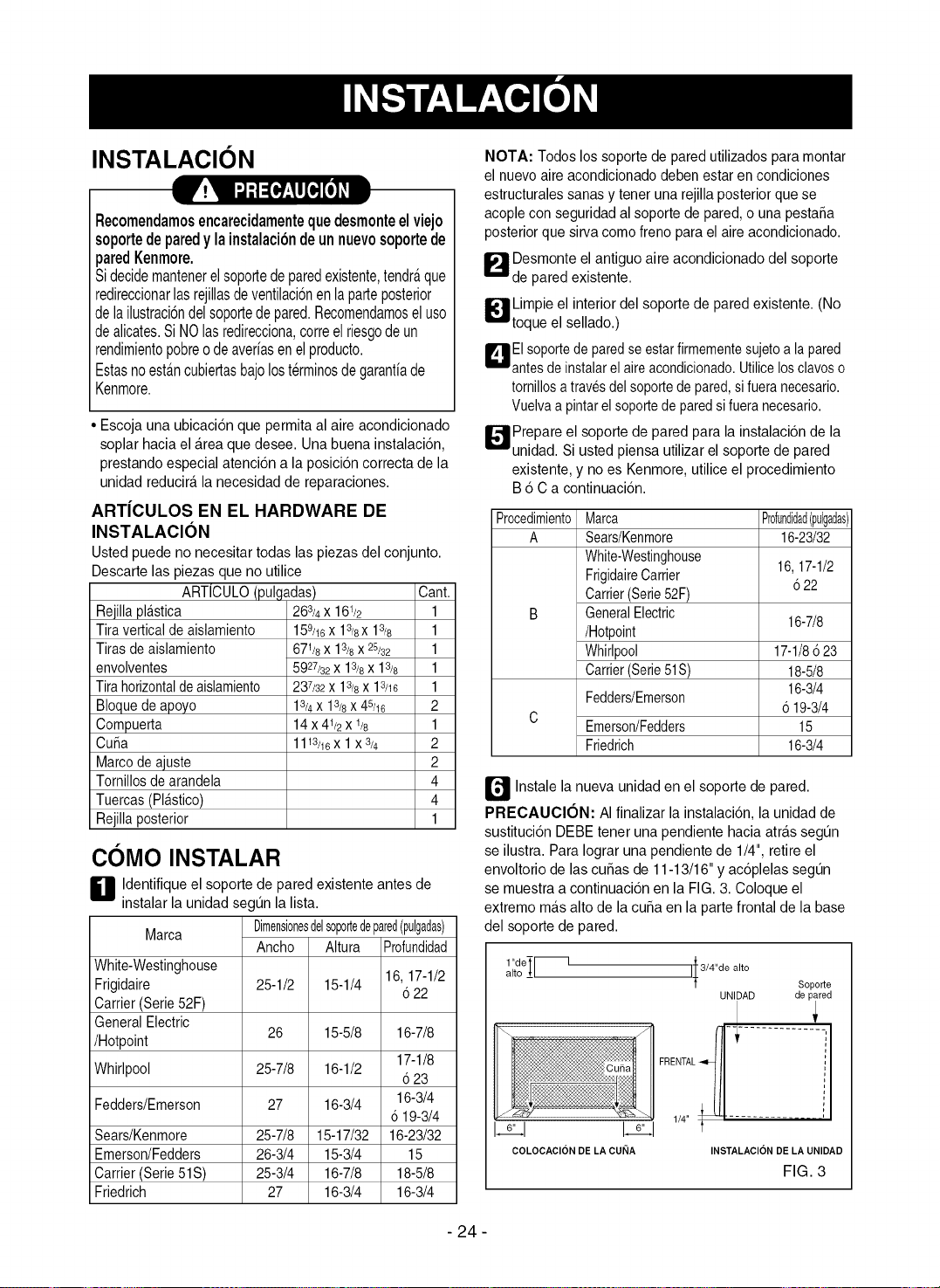
INSTALACION
I ! _l-'i=[I#:ll[!][olll
Recomendamosencarecidamentequedesmonteelviejo
soportedeparedy lainstalacibndeunnuevosoportede
paredKenmore.
Sidecidemantenerelsoportedeparedexistente,tendr_,que
redireccionarlasrejillasdeventilaci6nenlaparteposterior
delailustraci6ndelsoportedepared.Recomendamoseluso
dealicates.SiNOlasredirecciona,correelriesgodeun
rendimientopobreodeaverfasenelproducto.
Estasnoestancubiertasbajolosterminosdegarantfade
Kenmore.
Escoja unaubicacion que permitaal aire acondicionado
soplar hacia elArea quedesee. Unabuena instalacion,
prestando especial atencion a la posicion correcta de la
unidad reducira,la necesidadde reparaciones.
ARTJCULOS EN EL HARDWARE DE
INSTALACION
Usted puede no necesitar todas las piezas del conjunto.
Descarte las piezas que no utilice
ARTiCULO(pulgadas)
Reiillapla.stica
Tira verticalde aislamiento
Tiras deaislamiento
envolventes
Tirahorizontaldeaislamiento
Bloquedeapoyo
Compuerta
Cui_a
Marcode ajuste
Tomillos dearandela
Tuercas (Pl_stico)
Rejillaposterior
263/4 X 161/2
159/16 X 13/8X 13/8
671/6x 13/8x 25/32
5927/32 X13/6X13/6
237/32 X 13/8 X 13/16
13/4 X 13/8 X 45/16
14x 41/2 X 1/8
1113/16x 1x3/4
Cant.
1
1
1
1
1
2
1
2
2
4
4
1
COMO INSTALAR
H dentifique elsoporte de pared existente antes de
instalar la unidad segun la lista.
Marca Dimensi0nesdelsoportedepared(pulgadas)
White-Westinghouse
Frigidaire
Carrier(Serie 52F)
GeneralElectric
/Hotpoint
Whirlpool
Fedders/Emerson
Sears/Kenmore
Emerson/Fedders
Carrier(Serie 51S)
Friedrich
Ancho Altura
25-1/2 15-1/4
26 15-5/8
25-7/8 16-1/2
27 16-3/4
25-7/8 15-17/32
26-3/4 15-3/4
25-3/4 16-7/8
27 16-3/4
Profundidad
16, 17-1/2
622
16-7/8
17-1/8
6 23
16-3/4
6 19-3/4
16-23/32
15
18-5/8
16-3/4
NOTA: Todos lossoportede paredutilizadospara montar
el nuevoaire acondicionado debenestar en condiciones
estructuralessanas y tenet una rejillaposterior que se
acoplecon seguridadal soportede pared,o unapestaSa
posterior que sirva como freno para el aire acondicionado.
_1 Desmonte el antiguo aire acondicionado del soporte
de pared existente.
_ impie el interior del soporte de pared existente. (No
toque el sellado.)
EIsoportedeparedseestarfirmementesujetoa lapared
antesdeinstalarel aireacondicionado.Utilicelosclavoso
tornillosa travesdelsoportedepared,sifueranecesario.
Vuelvaa pintarel soportede paredsifueranecesario.
_41 Prepare el soporte de pared para la instalacion de la
unidad. Si usted piensa utilizar el soporte de pared
existente, y no es Kenmore, utiliceel procedimiento
B6 C a continuacion.
ProcedimientoMarca Pr0fundidad(pulgadas)
A Sears/Kenmore 16-23/32
White-Westinghouse
FrigidaireCarrier 16,17-1/2
622
Carrier(Serie52F)
B GeneralElectric
16-7/8
/Hotpoint
Whirlpool 17-1/8{523
Carrier(Serie51S) 18-5/8
16-3/4
Fedders/Emerson
6 19-3/4
C
Ernerson/Fedders 15
Friedrich 16-3/4
_ Instale la nueva unidad en el soporte de pared.
PRECAUCI6N: AIfinalizar la instalacion, la unidad de
sustitucion DEBE tenet una pendiente hacia atr_tssegun
se ilustra. Para Iograr una pendiente de 1/4", retire el
envoltorio de las cu_as de 11-13/16"y ac6plelas segun
se muestra a continuacion en la FIG. 3. Coloque el
extremo ma.salto de la cuba en la partefrontal de la base
del soporte de pared.
t"deTr--
alto ±L
I_,,I I_,,I
COLOCACION DE LA CURIA
l
I_3/4"de alto
1
Soporte
UNIDAD de pared
INSTALACION DE LA UNIDAD
FIG. 3
- 24 -
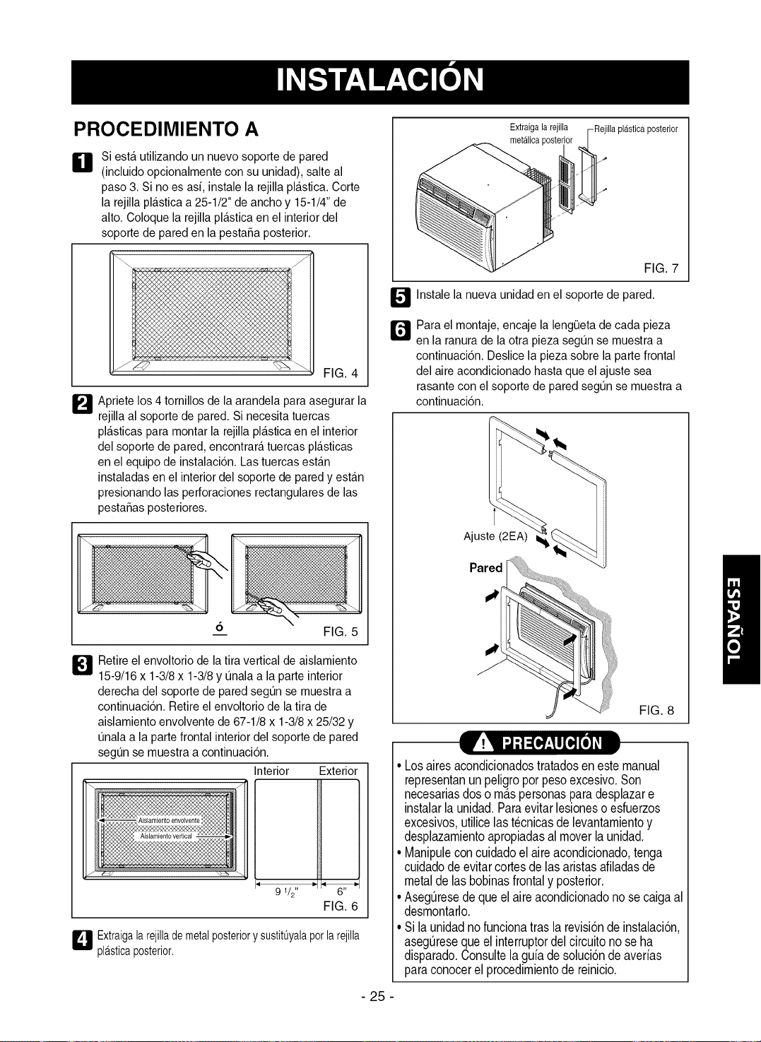
PROCEDIMIENTO A
IDI
Siesta utilizando un nuevo soporte de pared
(incluido opcionalmente con su unidad), salte al
paso3. Si no es asi, instale la rejilla plastic& Corte
la rejilla plastica a 25-1/2" de ancho y 15-1/4"de
alto. Coloque la rejilla pla.sticaen el interior del
soporte de pared en la pestafia posterior.
FIG. 4
_'_ Apriete los 4 tornillos de la arandela para asegurar la
rejilla al soporte de pared. Si necesita tuercas
pla.sticaspara montar la rejilla plastica en el interior
del soporte de pared, encontrara tuercas plasticas
en el equipo de instalaci6n. Las tuercas estan
instaladas en el interiordel soporte de pared y esta.n
presionando las perforaciones rectangulares de las
pestafias posteriores.
_1 Retire elenvoltorio de la tira vertical de aislamiento
15-9/16 x 1-3/8x 1-3/8y unala a la parte interior
derecha del soporte de pared segun se muestra a
continuaci6n. Retire elenvoltorio de latira de
aislamiento envolvente de 67-1/8 x 1-3/8 x 25/32 y
unala a la partefrontal interior del soporte de pared
segun se muestra acontinuaci6n.
Interior
9 1/2"
Exterior
FIG. 6
L_-! Extraigalarejillademetalposteriory sustitOyalapotlarejilla
plasticaposterior.
Extraigala rejilla -Rejilla plasticaposterior
metalicaposte_
FIG. 7
_ Instale la nueva unidad en el soporte de pared.
r_Para el montaje, encaje la lengeeta de cada pieza
en la ranura de laotra pieza segun se muestra a
continuaci6n. Deslice la pieza sobre la parte frontal
del aire acondicionado hastaque el ajuste sea
rasante con el soporte de pared segun se muestra a
continuaci6n.
Ajuste (2EA)
Pared
FIG. 8
• Losairesacondicionadostratadosenestemanual
representanunpeligroporpesoexcesivo.Son
necesariasdoso maspersonasparadesplazare
instalarla unidad.Paraevitarlesionesoesfuerzos
excesivos,utilicelast@nicasde levantamientoy
desplazamientoapropiadasal moverla unidad.
• Uanipuleconcuidadoelaireacondicionado,tenga
cuidadodeevitarcortesdelasaristasafiladasde
metaldelasbobinasfrontalyposterior.
• Asegt_resedequeelaireacondicionadonosecaigaal
desmontarlo.
• Sila unidadno funcionatrasla revisiondeinstalacion,
asegt_resequeelinterruptordelcircuitonoseha
disparado.Consultelaguiadesoluciondeaverias
paraconocerel procedimientodereinicio.
- 25 -
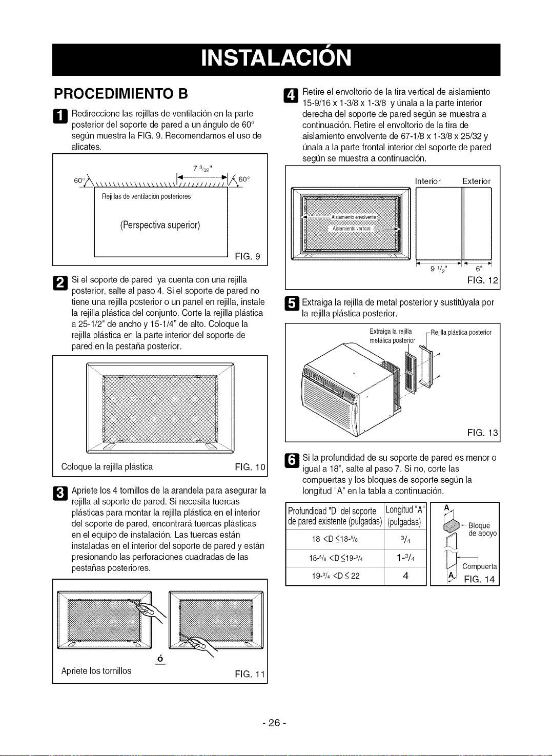
PROCEDIMIENTO B
H edireccione las rejillasde ventilaci6n en la parte
posterior del soporte de pared aun a.ngulode 60°
segun muestra la FIG. 9. Recomendamos el uso de
alicates.
7 3/32"
Rejillas de ventilaei6nposteriores
(Perspectivasuperior)
0o
FIG.
_'_Si el soporte de pared ya cuenta con una rejilla
posterior,salte al paso 4. Si el soporte de pared no
tiene una rejilla posterior o un panel en rejilla, instale
la rejilla pla.sticadel conjunto. Corte la rejilla pla.stica
a 25-1/2" de ancho y 15-1/4"de alto. Coloque la
rejilla plastica en laparte interior del soporte de
pareden la pestafia posterior.
Coloque la rejillapla.stica
_1 Apriete los 4 tornillos de la arandela para asegurar la
rejillaal soporte de pared. Si necesita tuercas
pla.sticaspara montar la rejilla plastica en elinterior
del soporte de pared, encontrara tuercas plasticas
en el equipo de instalaci6n. Las tuercas estan
instaladas en el interior del soporte de paredy esta.n
presionando las perforaciones cuadradas de las
pestafias posteriores.
L_ Retireel envoltorio de la tira vertical de aislamiento
15-9/16 x 1-3/8 x 1-3/8 y unala a la parte interior
derecha del soporte de paredsegun se muestra a
continuaci6n. Retireel envoltorio de la tira de
aislamiento envolvente de 67-1/8 x 1-3/8x 25/32 y
unala a la parte frontal interiordel soporte de pared
segun se muestra a continuaci6n.
Interior Exterior
!]
9 1/2"
FIG. 12
Extraiga la rejilla de metal posterior y sustituyala pot
_"'_ la rejilla pla.sticaposterior.
Extraigala rejilla -Rejilla plasticaposterior
metalicapostel
FIG. 13
r_si la profundidad de su soporte de pared es menor o
FIG. 10 igual a 18", salte al paso 7. Si no, corte las
compuertas y los bloques de soporte segun la
Iongitud "A"en la tabla a continuaci6n.
Pr0fundidad"D"dels0p0rte
deparedexistente(pulgadas)
18 <D _<18-s/8
18-s/8<D_<19-3/4
19-3/4<D _<22
Longitud"A"
(pulgadas)
3/4
1-3/4
4
Bloque
de apoyo
_ Compuerta
_J FIG. 14
6
Apriete los tornillos FIG. 11
- 26 -
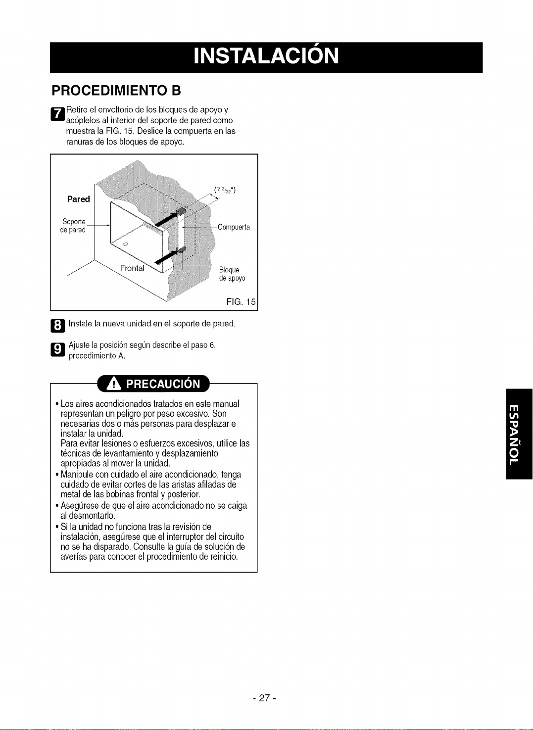
PROCEDIMIENTO B
W etire el envoltorio de los bloques de apoyo y
ac6plelos al interiordel soporte de pared corno
rnuestrala FIG. 15. Deslice lacornpuerta en las
ranuras de los bloques de apoyo.
Pared
Soporte
depared
Frontal
7 3/32")
deapoyo
FIG. 15
_I Instale la nueva unidad en el soporte de pared.
_1 Ajuste laposici6nsegt_ndescribeel paso6,
procedimientoA.
•Losairesacondicionadostratadosenestemanual
representanunpeligroporpesoexcesivo.Son
necesariasdosornaspersonasparadesplazare
instalarlaunidad.
Paraevitarlesioneso esfuerzosexcesivos,utilicelas
tecnicasdelevantarnientoy desplazarniento
apropiadasal moverlaunidad.
•Uanipuleconcuidadoelaireacondicionado,tenga
cuidadode evitarcortesde lasaristasafiladasde
metaldelasbobinasfrontaly posterior.
•Asegt_resedequeelaireacondicionadonosecaiga
aldesrnontarlo.
•Si launidadnofuncionatraslarevisionde
instalacion,asegt_resequeel interruptordelcircuito
nosehadisparado.Consultelaguiadesolucionde
averiasparaconocerel procedirnientode reinicio.
- 27 -
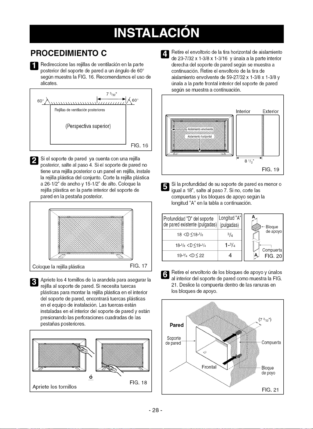
PROCEDIMIENTO C
H edireccione las rejillasde ventilaci6n en la parte
posterior del soporte de pared aun angulo de 60°
segun muestra la FIG. 16. Recomendamosel uso de
alicates.
7 3/32"
Rejillasdeventilaci6nposteriores
(Perspectivasuperior)
/,_60 °
FIG. 16
_'_Si el soporte de pared ya cuenta con una rejilla
posterior,salte al paso 4. Si el soporte de pared no
tiene una rejilla posterior o un panel en rejilla, instale
la rejilla pla.sticadel conjunto. Corte la rejilla pla.stica
a 26-1/2" de ancho y 15-1/2"de alto. Coloque la
rejilla plastica en laparte interior del soporte de
pareden la pestaSaposterior.
C
Coloque la rejilla pla.stica FIG. 17
_1 Apriete los 4 tornillos de la arandela para asegurar la
rejillaal soporte de pared. Si necesita tuercas
pla.sticaspara montar la rejilla plastica en elinterior
del soporte de pared, encontrara tuercas plasticas
en el equipo de instalaci6n. Las tuercas estan
instaladas en el interior del soporte de paredy esta.n
presionando las perforaciones cuadradas de las
pestaSasposteriores.
Apriete los tornillos
6
FIG. 18
_1 Retire el envoltorio de la tira horizontalde aislamiento
de 23-7/32 x 1-3/8x 1-3/16 y t]nalaa la parte interior
derecha del soportede paredsegt]n se muestra a
continuaci6n. Retireel envoltorio de la tira de
aislamiento envolvente de 59-27/32 x 1-3/8 x 1-3/8y
t]nalaa la partefrontal interiordel soporte de pared
segt]n se muestraa continuaci6n.
Interior Exterior
-i t-
8 1/2"
FIG. 19
_"_ Si la profundidad de susoporte de pared es menor o
igual a 18", salte al paso 7. Si no, corte las
compuertas y los bloques de apoyo segun la
Iongitud"A" en la tabla a continuacion.
Profundidad"D"delsoporte
deparedexistente(pulgadas)
18 <D _<18-%
18-s/8<D_<19-3/4
19-3/4<D _<22
Longitud"A"
(pulgadas)
3/4
1-3/4
4
_-- Bloque
._ de apoyo
"_ Compuerta
FIG. 20
r_ Retireel envoltorio de los bloques de apoyo y unalos
al interior del soporte de pared como muestra la FIG.
21. Deslice la compuerta dentro de las ranuras en
los bloques de apoyo.
Pared
Soporte
de pared
.......;ii
i
FIG. 21
- 28 -
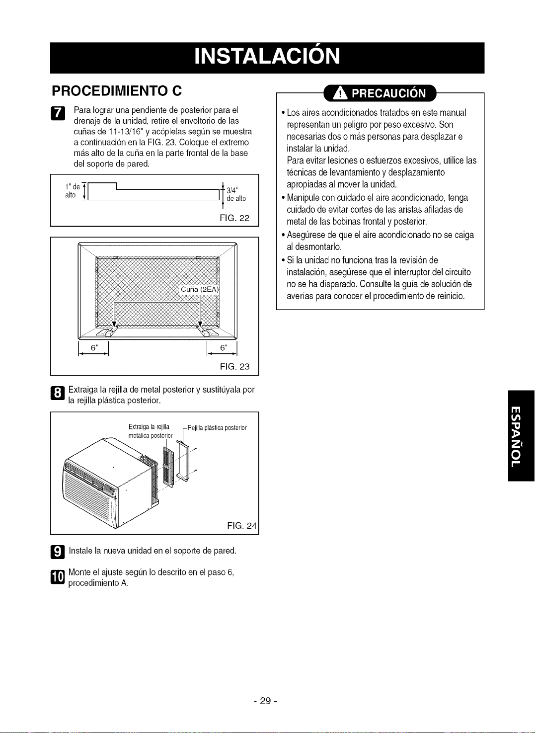
PROCEDIMIENTO C
W
Para Iograr una pendiente de posterior para el
drenaje de la unidad, retire el envoltorio de las
cutlas de 11-13/16" y ac6plelas segun se muestra
a continuaci6n en la FIG.23. Coloque el extremo
ma.salto de la curia en la parte frontal de la base
del soporte de pared.
1"deT [--] _-3/4"
alto __/ f deato
/
FIG.22
6" 6"
FIG. 23
Extraiga la rejilla de metal posterior y sustituyala pot
l_Ila rejillapla.sticaposterior.
Extraigala rejilla
metalicaposter
FIG. 24
_'_ Instale la nueva unidad en elsoporte de pared.
_] onte el ajuste segun Iodescrito en el paso 6,
procedimiento A.
_.t 1 :,1:t ::(@__l[e,][e]#--_
• Losairesacondicionadostratadosen estemanual
representanunpeligroporpesoexcesivo.Son
necesariasdoso maspersonasparadesplazare
instalarlaunidad.
Paraevitarlesioneso esfuerzosexcesivos,utilicelas
t@nicasde levantamientoydesplazamiento
apropiadasal moverlaunidad.
• Uanipuleconcuidadoel aireacondicionado,tenga
cuidadodeevitarcortesde lasaristasafiladasde
metalde lasbobinasfrontaly posterior.
•Aseg0resedequeel aireacondicionadonosecaiga
al desmontarlo.
•Si launidadnofuncionatraslarevisionde
instalacion,aseg0resequeel interruptordelcircuito
nosehadisparado.Consultelaguiadesolucionde
averiasparaconocerel procedimientode reinicio.
- 29 -
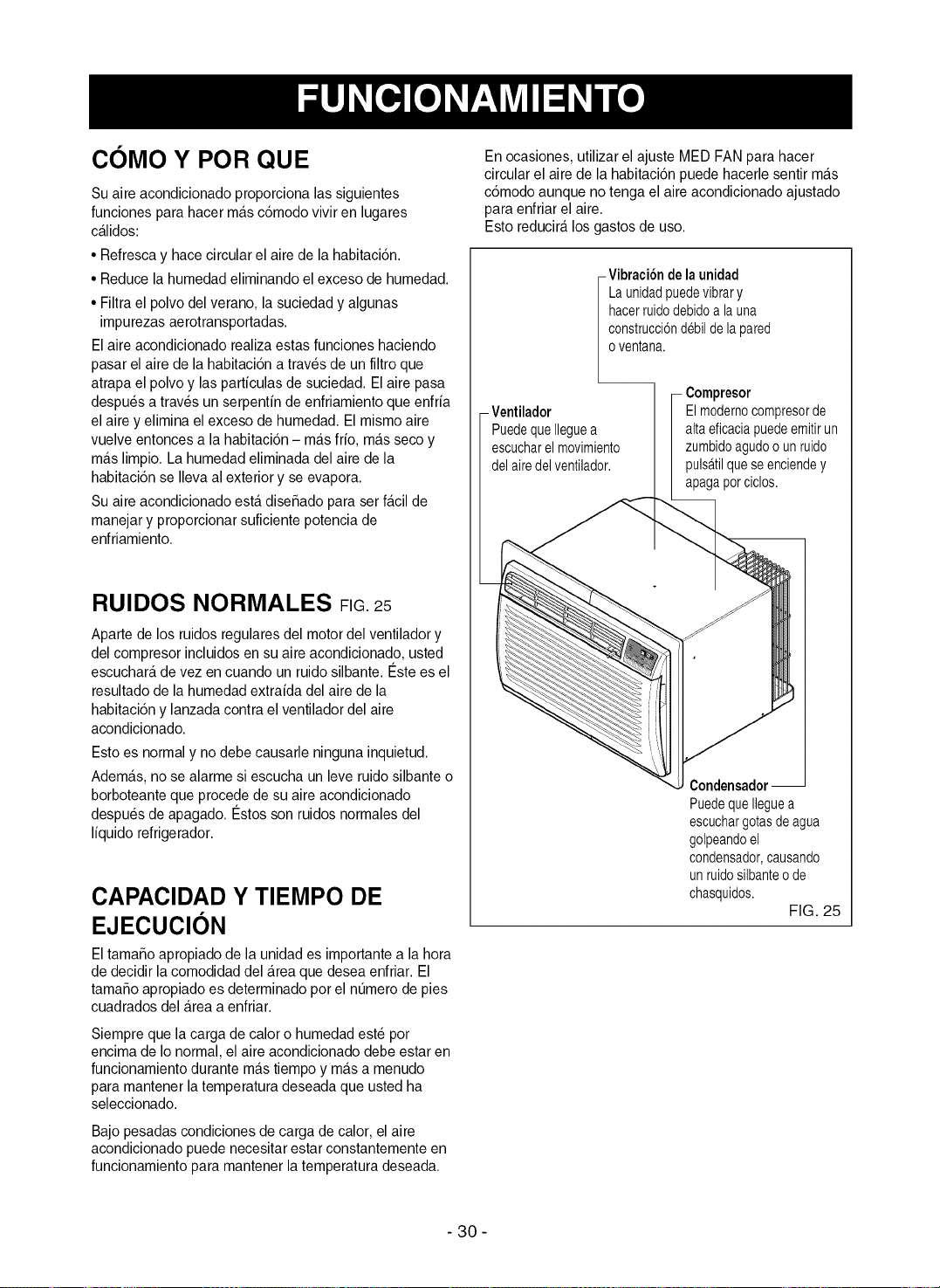
COMO Y POR QUE
Su aire acondicionado proporciona las siguientes
funciones para hacer ma.sc6modo vivir en lugares
ca.lidos:
• Refresca y hace circular el aire de la habitaci6n.
• Reduce la humedad eliminando el exceso de humedad.
• Filtra el polvo del verano, la suciedad y algunas
impurezas aerotransportadas.
El aire acondicionado realizaestas funciones haciendo
pasar el aire de la habitaci6n atraves de un filtro que
atrapa el polvo y las particulas de suciedad. El aire pasa
despues a traves un serpentin de enfriamiento que enfria
el aire y elimina el exceso de humedad. El mismo aire
vuelve entonces a la habitaci6n - ma.sfrio, ma.sseco y
ma.slimpio. La humedadeliminada del aire de la
habitaci6n se Ileva al exterior y se evapora.
Su aire acondicionado esta.disefiado para set fa.cilde
manejar y proporcionar suficiente potencia de
enfriamiento.
RUIDOS NORMALES FIG.25
Aparte de los ruidos regulates del motor del ventilador y
del compresor incluidos en su aire acondicionado, usted
escuchara,de vez en cuando un ruido silbante. €:stees el
resultado de la humedad extraida del aire de la
habitaci6n y lanzada contra el ventilador del aire
acondicionado.
Esto es normal y no debe causarle ninguna inquietud.
Adema.s,no se alarme si escucha un leve ruido silbante o
borboteante que procede de su aireacondicionado
despues de apagado. €:stos son ruidos normales del
liquido refrigerador.
CAPACIDAD Y TIEMPO DE
EJECUClON
El tamafioapropiado de la unidad es importante a la hora
de decidir la comodidad del Areaque desea enfriar. El
tamafio apropiado es determinado pot el numero de pies
cuadrados del Areaa enfriar.
Siempre que la carga de calor o humedad este pot
encima de Ionormal, el aire acondicionado debe estar en
funcionamiento durante ma.stiempo y ma.sa menudo
para mantener la temperatura deseada que usted ha
seleccionado.
Bajo pesadas condiciones de carga de calor, el aire
acondicionado puede necesitar estar constantemente en
funcionamiento para mantener la temperatura deseada.
En ocasiones, utilizar el ajuste MED FAN para hacer
circular el aire de la habitacion puede hacerlesentir ma.s
c6modo aunque no tenga el aire acondicionado ajustado
para enfriar el aire.
Esto reducira,los gastos de uso.
- Vibraci6ndela unidad
Launidadpuedevibrary
hacerruidodebidoa launa
construcci6ndebildelapared
oventana.
- Ventilador
PuedequeIleguea
escucharelmovimiento
delairedelventilador.
_resor
El modernocompresorde
altaeficaciapuedeemitirun
zumbidoagudoounruido
pulsatilqueseenciendey
apagaporciclos.
Condensador--
PuedequeIleguea
escuchargotasdeagua
golpeandoel
condensador,causando
unruidosilbanteode
chasquidos.
FIG. 25
- 30 -
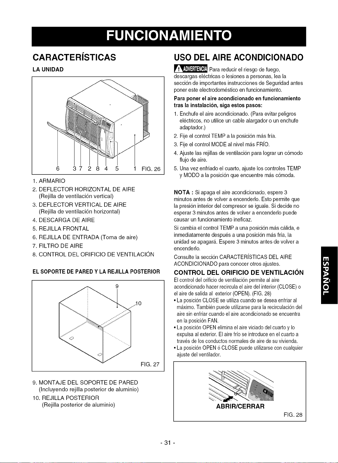
CARACTERiSTICAS
LA UNIDAD
6 3 7 2 8 4 5 1 FIG. 26
1. ARMARIO
2. DEFLECTOR HORIZONTAL DE AIRE
(Rejilla de ventilaci6n vertical)
3. DEFLECTOR VERTICAL DE AIRE
(Rejilla de ventilaci6n horizontal)
4. DESCARGA DE AIRE
5. REJILLA FRONTAL
6. REJILLA DE ENTRADA (Toma de aire)
7. FILTRO DE AIRE
8. CONTROL DEL ORIFICIO DE VENTILACION
EL SOPORTE DE PARED Y LA REJILLA POSTERIOR
FIG. 27
9. MONTAJE DEL SOPORTE DE PARED
(Incluyendo rejilla posterior de aluminio)
10. REJILLA POSTERIOR
(Rejilla posterior de aluminio)
USO DEL AIRE ACONDIClONADO
Para reducir el riesgo de fuego,
descargas electricas o lesionesa personas, lea la
secci6n de importantes instrucciones de Seguridad antes
poner este electrodomestico en funcionamiento.
Para poner el aire acondicionado en funcionamiento
tras la instalaci6n, siga estos pasos:
1. Enchufe el aire acondicionado. (Para evitar peligros
electricos, no utilice un cable alargador o un enchufe
adaptador.)
2. Fije el control TEMP a la posici6n ma.sfria.
3. Fije el control MODE al nivel ma.sFR/O.
4. Ajuste las rejillasde ventilaci6n para Iograr un c6modo
flujo de aire.
5. Unavez enfriado el cuarto, ajuste los controles TEMP
y MODO a la posici6n queencuentre ma.sc6moda.
NOTA : Si apaga el aire acondicionado, espere 3
minutos antes de volver a encenderlo. Esto permite que
la presi6n interior del compresor se iguale. Si decide no
esperar 3 minutos antes de volver a encenderlo puede
causar un funcionamiento ineficaz.
Si cambia el control TEMP a una posici6n ma.sca.lida,e
inmediatamente despues a una posicion ma.sfria, la
unidad se apagar& Espere3 minutos antesde volver a
encenderlo.
Consulte la seccion CARACTER/STICAS DELAIRE
ACONDICIONADO para conocer otros ajustes.
CONTROL DEL ORIFICIO DE VENTILACION
Elcontrol delorificiode ventilaci6npermiteal aire
acondicionadohacerrecirculaelairedel interior(CLOSE)o
el aire desalidaal exterior(OPEN).(FIG.28)
• Laposici6nCLOSEse utilizacuandose deseaenfriaral
m&ximo.Tambienpuedeutilizarsepara la recirculaci6ndel
airesin enfriarcuandoel aire acondicionadose encuentra
en laposici6nFAN.
• Laposici6nOPENeliminael aireviciadodelcuarto y Io
expulsaal exterior.El airefrio se introduceen el cuarto a
travesde losconductosnormalesde aire desu vivienda.
• Laposici6nOPEN6CLOSEpuedeutilizarseconcualquier
ajustedelventilador.
ABRIR/CERRAR
FIG. 28
- 31 -
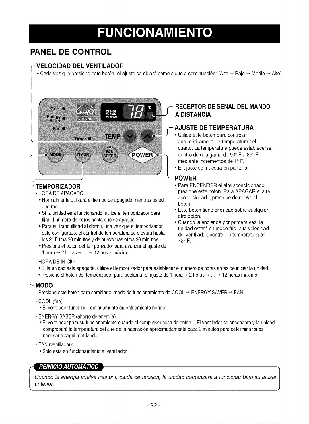
PANEL DE CONTROL
-VELOCIDAD DEL VENTILADOR
• Cada vez que presione este bot6n, el ajuste cambiara como sigue a continuaci6n: {Alto _ Bajo _ Medio _ Alto}
RECEPTOR DE SENAL DEL MANDO
A DISTANCIA
AJUSTE DE TEMPERATURA
• Utilice este bot6n para controlar
automaticamente la temperatura del
cuarto. La temperatura puede establecerse
dentro de una gama de 600F a 860 F
mediante incrementos de 1° F.
• El ajuste se muestra en pantalla.
_-TEMPORIZADOR
- HORA DEAPAGADO
• Norrnalrnenteutilizar_,el tiernpode apagado rnientras usted
duerrne.
• Si la unidad esta.funcionando, utilice el ternporizador para
fijar elntJrnerode horas hasta que se apague.
• Para sutranquilidad al dorrnir,unavez que el ternporizador
este configurado, el control de ternperatura se elevate,hasta
los 20 Ftras 30 rninutosy de nuevotras otros 30 rninutos.
• Presione el botdn del ternporizador para avanzar el ajuste de
1hora _ 2 horas_ ... _ 12 horas rn_irno.
POWER
• Para ENCENDER el aire acondicionado,
presione este bot6n. Para APAGAR el aire
acondicionado, presione de nuevo el
bot6n.
• Este bot6n tiene prioridad sobre cualquier
otro bot6n.
• Cuando la encienda por primera vez, la
unidad estara en modo frio, alta velocidad
del ventilador, control de temperatura en
720F.
- HORA DE INICIO
• Si la unidad est,. apagada, utilice el temporizador para establecer el ntJmerode horas antesde iniciar la unidad.
• Presione el botdn del temporizador para adelantar el ajuste de 1 hora _ 2 horas _ ... _ 12 horas m_.ximo.
MODO
- Presioneeste bot6n para cambiar el modo de funcionamiento de COOL _ ENERGY SAVER_ FAN.
- COOL (frio):
• El ventilador funciona continuarnente en enfriarniento normal
- ENERGY SABER (ahorro de energia):
• El ventilador para su funcionamientocuando el compresor cesa de enfriar. Elventilador se encender_,y la unidad
cornprobar_,la ternperatura delaire de la habitaci6naproxirnadarnente cada 3 rninutospara deterrninarsi es
necesario seguir enfriando.
- FAN (ventilador):
• S61oest,. en funcionamiento el ventilador.
[
Cuando la energfa vuelva tras una cafda de tensidn, la unidad comenzara a funcionar bajo su ajuste
anterior.
- 32 -
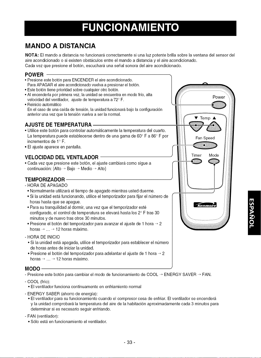
MANDO A DISTANCIA
NOTA: El mando a distancia no funcionara correctamente si una luz potente brilla sobre la ventana del sensor del
aire acondicionado o si existen obstaculos entre el mando a distancia y el aire acondicionado.
Cada vez que presione el bot6n, escuchara una se5al sonora del aire acondicionado.
POWER
• Presioneeste bot6n para ENCENDERel aireacondicionado.
ParaAPAGAR el aire acondicionado vuelva a presionarel bot6n.
• Este bot6n tiene prioridad sobre cualquier otto bot6n.
• AI encenderla perprimera vez, la unidad se encuentra en mode frio, alta
velocidad del ventilador, ajustede temperatura a 72° F.
• Reinicio automa.tico
Enel case de una caida de tensi6n, la unidad funcionara,bajo la configuraci6n
anterior unavez que la tensi6n vuelva a set la normal.
f
Power
AJUSTE DE TEMPERATURA
• Utilice este bot6n para controlar automa.ticamente la temperatura del cuarto.
La temperatura puede establecerse dentro de una gama de 60° F a 86oF por
incrementos de 1° F.
• El ajuste aparece en pantalla.
VELOCIDAD DEL VENTILADOR
• Cada vez que presione este bot6n, el ajuste cambiara como sigue a
continuaci6n: {Alto _ Bajo _ Medio _ Alto}
TEMPORIZADOR
- HORA DE APAGADO
• Normalmente utilizara el tiempo de apagado mientras usted duerme.
• Si la unidad esta.funcionando, utilice el temporizador para fijar el nt_mero de
horas hasta que se apague.
• Para su tranquilidad al dormir, una vez que el temporizador este
configurado, el control de temperatura se elevara hasta los 2oF tras 30
minutos y de nuevo tras otros 30 minutos.
• Presione el bot6n del temporizador para avanzar el ajuste de 1 hora _ 2
horas _ ... _ 12 horas m_imo.
- HORA DE INICIO
• Si la unidad esta apagada, utilice el temporizador para establecer el nt_mero
de horas antes de iniciar la unidad.
• Presione el bot6n del temporizador para adelantar el ajuste de 1 hora _ 2
horas _ ... _ 12 horas maximo.
Fan Speed
Timer Mode
MODO
- Presione este bot6n para cambiar el modo de funcionamiento de COOL _ ENERGY SAVER _ FAN.
- COOL (frfo):
• El ventilador funciona continuamente en enfriamiento normal
- ENERGY SABER (ahorro de energfa):
• El ventilador para su funcionamiento cuando el compresor cesa de enfriar. El ventilador se encendera
y la unidad comprobara la temperatura del aire de la habitaci6n aproximadamente cada 3 minutos para
determinar si es necesario seguir enfriando.
- FAN (ventilador):
• $61o est,. en funcionamiento el ventilador.
- 33 -
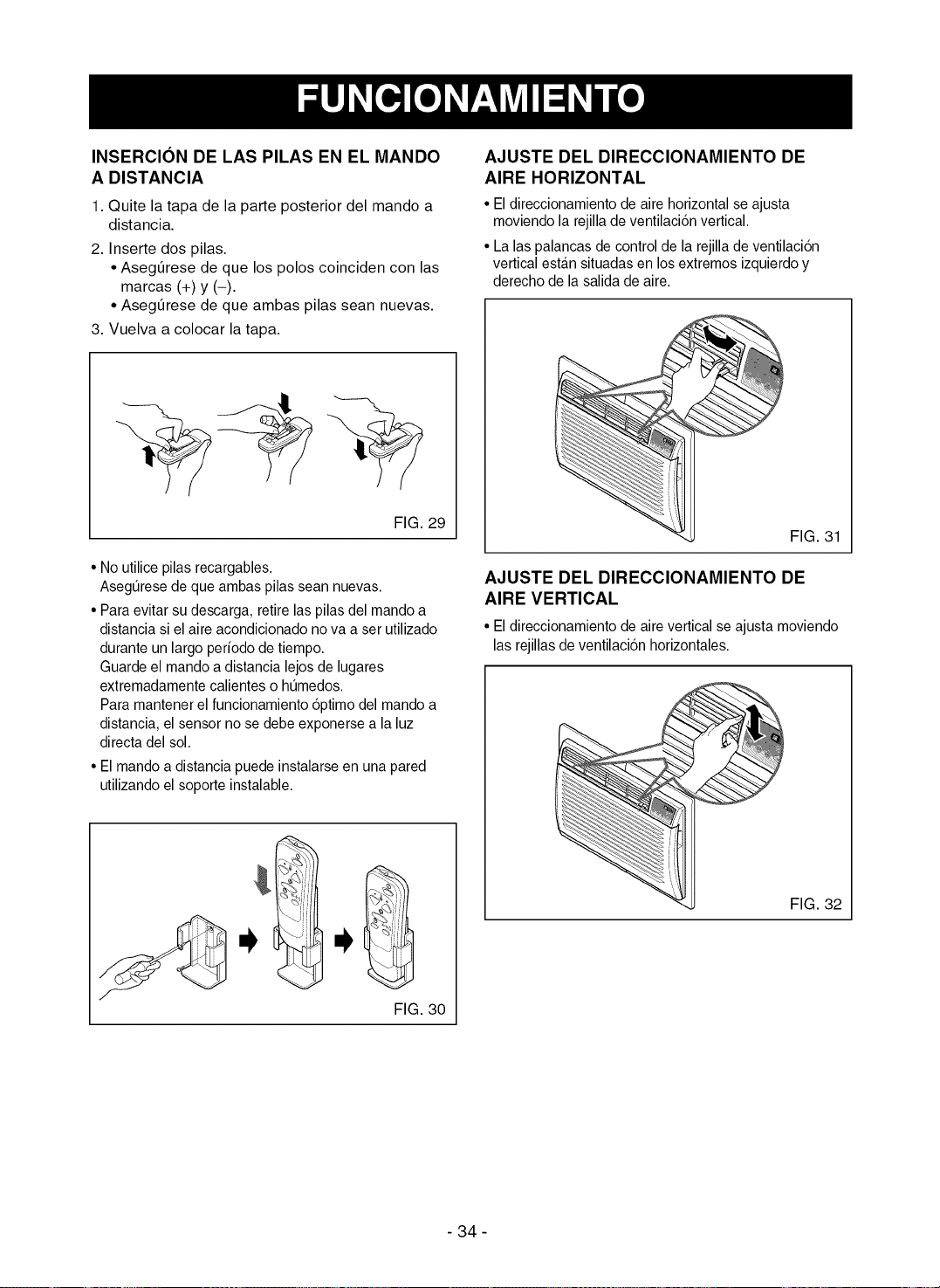
INSERCION DE LAS PILAS EN EL MANDO
A DISTANCIA
1. Quite la tapa de la parte posterior del mando a
distancia.
2. Inserte dos pilas.
• Asegt_rese de que los polos coinciden con las
marcas (+) y (-).
• Asegt]rese de que ambas pilas sean nuevas.
3. Vuelva a colocar la tapa.
FIG. 29
• No utilice pilas recargables.
Asegurese de que ambas pilas sean nuevas.
• Para evitar su descarga, retire las pilas del mando a
distancia si el aireacondicionado no va a set utilizado
durante un largo periodo de tiempo.
Guarde el mando a distancia lejos de lugares
extremadamente calientes o humedos.
Para mantener el funcionamiento 6ptimo del mando a
distancia, el sensor no sedebe exponerse a la luz
directa del sol.
• El mando a distancia puede instalarse en una pared
utilizando el soporte instalable.
AJUSTE DEL DIRECCIONAMIENTO DE
AIRE HORIZONTAL
• El direccionamiento de aire horizontal se ajusta
moviendo la rejilla de ventilacion vertical.
• La las palancas de control de la rejillade ventilacion
vertical estan situadas en los extremos izquierdo y
derecho de la salida de aire.
FIG. 31
AJUSTE DEL DIRECCIONAMIENTO DE
AIRE VERTICAL
• El direccionamiento de aire vertical seajusta moviendo
las rejillas de ventilaci6n horizontales.
FIG. 30
FIG. 32
- 34 -
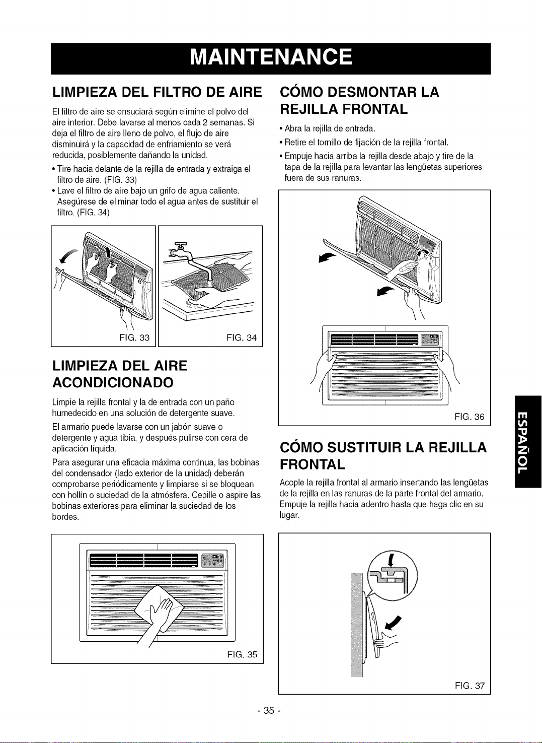
LIMPIEZA DEL FILTRO DE AIRE
El filtro de airese ensuciara segun elimine el polvo del
aire interior. Debe lavarse al menos cada 2 semanas. Si
deja el filtro de aire Ileno de polvo, el flujo de aire
disminuira y la capacidad de enfriamiento severa
reducida, posiblemente dafiando la unidad.
• Tire hacia delante de la rejilla de entrada y extraiga el
filtro de aire. (FIG. 33)
• Lave el filtro de aire bajo un grifo de agua caliente.
Asegurese de eliminar todo el agua antes de sustituir el
filtro. (FIG. 34)
FIG. 33 FIG. 34
LIMPIEZA DEL AIRE
ACONDICIONADO
Limpie la rejilla frontal y la de entrada con un patio
humedecido en una solucion de detergente suave.
El armario puede lavarse con un jab6n suave o
detergente y agua tibia, y despues pulirse con cera de
aplicacion liquid&
Para asegurar una eficacia maxima continua, las bobinas
del condensador (lado exterior de la unidad) deberan
comprobarse periodicamente y limpiarse si se bloquean
con hollin o suciedad de la atmosfera. Cepille o aspire las
bobinas exteriores para eliminar la suciedad de los
bordes.
C0MO DESMONTAR LA
REJILLA FRONTAL
• Abra la rejillade entrada.
• Retire el tornillode fijacion de la rejillafrontal.
• Empuje hacia arriba la rejilladesde abajo y tire de la
tapa de la rejilla para levantar las lengeetas superiores
fuera de sus ranuras.
I
FIG. 36
COMO SUSTITUlR LA REJILLA
FRONTAL
Acople la rejilla frontal al armario insertando las lengQetas
de la rejilla en las ranuras de la parte frontal del armario.
Empuje la rejilla hacia adentro hasta que haga clic en su
lugar.
I
FIG. 35
FIG. 37
- 35 -
ANTES DE LLAMAR AL SERVICIO DE REPARACION
Compruebe lalista a continuaci6n para asegurarse de que Ilamar al servicio de reparaci6n es realmente necesario.
Una consulta rapida a este manual puede ayudarle a evitar una Ilamada innecesaria alservicio de reparaci6n.
EL AIRE ACONDICIONADO NO FUNCIONA
Compruebe si... Despu_s...
El dispositivo interruptor de corriente est,. activado. Presione el bot6n RESET situado en la carcasa del enchufe del cable de
alimentaci6n.
Si el bet6n RESET no permanece presionado, deje de utilizar el equipo y
p6ngase en contacto con un tecnico de servicio cualificado.
El enchufe de pared est,. desconectado. Empuje el enchufe firmemente contra la toma de pared.
Fusible fundido o interruptor de circuito activado. Sustituya el fusible por uno de tipo de retardo o reinicie el interruptor de circuito.
Equipo APAGADO. Presione el botdn Power.
La unidadse apago ydespu6s se encendb demasiado rapidamente. Apague la unidad y espere 3 minutos antes de volver a encenderla.
El controlde TEMP esta mas calido que la temperaturaambiente. Establezca el control TEMP a un nOmero m_.sinferior.
EL AIRE DE LA UNIDAD NO SALE LO SUFICIENTEMENTE FR|O.
Compruebe si... Despu_s...
VELOCIDAD DEL VENTILADOR establecida en BAJA. Presione el bot6n FAN SPEED para fijarlo en HI.
Control de TEMP establecido en demasiado ca.lido. Fije el control TEMP a una temperatura ma.sinferior.
Temperatura ambiente per debajo de los 70° F (21 ° C). El enfriamiento puede no ocurrir hasta que la temperatura ambiente sea
superior a 70 ° F (21 ° C).
El conducto de detecci6n de temperatura est,. en contacto Enderece el conducto lejos de la bobina de evaporador.
con la bobina del evaporador, ubicada tras la rejilla frontal.
EL AIRE ACONDICIONADO ENFRIA, PERO EL CUARTO EST.&,DEMASIADO C_,LIDO - SE EST.&,FORMANDO HIELO TR_,S LA REJILLA DE ENTRADA.
Compruebe si... Despu_s...
Temperatura ambiente per debajo de los 70° F (21" C). Para descongelar la bobina, fije el MODO a VENTILADOR,
y la velocidad del ventilador a Alta.
El filtro de aire puede estar sucio. Limpie el filtro de aire. Consulte la secci6n de mantenimiento en el manual
del propietario.
Control TEMP fijado demasiado bajo. Para descengelar la bobina, fije el MODO a Cool, la velocidad del
ventilador a Alta, y el control TEMP a una temperatura m_.s alta.
EL AIRE ACONDICIONADO ENFRiA, PERO EL CUARTO EST.&. DEMASIADO CALIDO
Compruebe si... Despu_s...
Filtro de aire sucio - aire restringido. Limpie el filtro de aire. Consulte la secciSn de mantenimiento del manual del
propietario.
EL control TEMP esta fijado a demasiado caliente. Fije el control de TEMP a una temperatura ma.s inferior.
La parte frontal de la unidad est,. bloqueada por persianas, Elimine la obstrucci6n de delante de la unidad.
cortinas, muebles, etc. La distribucidn del aire esta. restricta.
Las puertas, ventanas, registros, etc. Est_.n abiertos. Cierre las puertas, ventanas, registros, etc.
El aire fifo se escapa.
Unidad recientemente encendida en un cuarto caliente. Concede un tiempo adicional para a eliminacidn del calor almacenado
en paredes, techo, suelo, y muebles.
EL AIRE ACONDICIONADO SE ENCIENDE Y APAGA RAPIDAMENTE.
Compruebe si... Despu_s...
La temperatura exterior es extremadamente caliente. Fije la VELOCIDAD del VENTILADOR en HI para reducir al mfnimo la
carga de enfriamiento.
La unidad esta.fijada en mode de ahorro de energia. Aproximadamente cada 3 minutes, el ventilador se encendera, y la unidad
comprobara, la temperatura del aire del cuarto para determinar si es
necesario enfriarlo. Este es el funcionamiento normal del modo ahorro de
energia.
RUIDOS CUANDO LA UNIDAD ESTA ENFRIANDO.
Compruebe si... Despu_s...
Ruido del ventilador golpeando agua - del sistema de Esto es normal cuando la humedad es alta. Cierre puertas, ventanas, y
eliminacidn de humedad, registros.
Vibraci6n de la ventana - instalaci6n defectuosa Consulte las instrucciones de instalaci6n o consulte con el instalador.
GOTEO DE AGUA DENTRO DEL CUARTO CUANDO LA UNIDAD ESTA ENFRIANDO.
Compruebe si... Despu_s...
El aire acondicionado estdt instalado incorrectamente. Incline el aire acondicionado levemente hacia el exterior para permitir el
drenaje del agua. Consulte las instrucciones de instalaci6n o consulte con
el instalador.
GOTEO DE AGUA EN EL EXTERIOR CUANDO LA UNIDAD ESTA ENFRIANDO.
Compruebe si... Despu_s...
La unidad estdt eliminando grandes cantidades de Esto es normal durante los dfas excesivamente humedos.
humedad de un cuarto humedo.
- 36 -
_37 _

- 38 -
Master Protection Agreements
Congratulations on making a smart purchase. Your new
Kenmore ® product is designed and manufactured for
years of dependable operation. But like all products, it
may require preventive maintenance or repair from time
to time. That's when having a Master Protection
Agreement can save you money and aggravation.
The Master Protection Agreement also helps extend the
life of your new product. Here's what the Agreement*
includes:
[] Parts and labor needed to help keep products
operating properly under normal use, not just
defects. Our coverage goes well beyond the
product warranty. No deductibles, no functional
failure excluded from coverage-- real protection.
[] Expert service by a force of more than 10,000
authorized Sears service technicians, which
means someone you can trust will be working on
your product.
[] Unlimited service calls and nationwide service,
as often as you want us, whenever you want us.
[] "No-lemon" guarantee - replacement of your
covered product if four or more product failures
occur within twelve months.
[] Product replacement if your covered product can't
be fixed.
[] Annual Preventive Maintenance Check at your
request - no extra charge.
[] Fast help by phone- we call it Rapid Resolution
- phone support from a Sears representative on all
products. Think of us as a "talking owner's manual."
[] Power surge protection against electrical damage
due to power fluctuations.
[] $250 Food Loss Protection annually for any food
spoilage that is the result of mechanical failure of
any covered refrigerator or freezer.
[] Rental reimbursement if repair of your covered
product takes longer than promised.
[] 10% discount off the regular price of any non-
covered repair service and related installed parts.
Once you purchase the Agreement, a simple phone
call is all that it takes for you to schedule service.
You can call anytime day or night, or schedule a service
appointment online.
The Master Protection Agreement is a risk free purchase.
If you cancel for any reason during the product warranty
period, we will provide a full refund. Or, a prorated refund
anytime after the product warranty period expires.
Purchase your Master Protection Agreement today!
Some limitations and exclusions apply.
For prices and additional information in the U.S.A.
call 1-800-827-6655.
* Coverage in Canada varies on some items. For
full details call Sears Canada at 1-800-361-6665.
Sears Installation Service
For Sears professional installation of home appliances,
garage door openers, water heaters, and other major
home items, in the U.S.A. or Canada call
1-800-4-MY-HOME®.
Contratos de proteccion maestra
Felicitaciones pot su compra inteligente. Su nuevo producto
Kenmore ®esta diseSado y fabricado para muchos argosde
operaci6n confiable. Sin embargo, al igual que todos los
puede requerir de mantenimiento o reparaci6n productos,
preventivas de vez en cuando. Es ahi cuando el contrato de
protecci6n maestra le puede ahorrar dinero y molestias.
El Contrato de protecci6n maestra tambien le ayuda a ampliar
la vida de su nuevo producto. Lo siguiente es Ioque se incluye
en el contrato*:
[] Piezas y mano de obra necesaria para ayudar a mantener
los productos en funcionamiento adecuado bajo un uso
normal, no s61odefectos. Nuestra cobertura va mucho
mas all_ de la garantia del producto. Sin franquicia, ni
falla funcional excluidos de la cobertura-- proteccion real.
[] 8ervicio experto otorgado por un grupo de mas de 10,000
tecnicos de reparaci6n autorizados de Sears, Io que significa
que alguien en quien usted confia trabajara con su producto.
[] 8ervicio ilimitado a domicilio en toda la nacion, cuantas
veces quiera, cuando Io necesite.
[] Garantia contra productos defectuosos reposici6n de su
producto cubierto si ocurren cuatro o mas fallas del producto
dentro de doce meses.
[] Reposicion del producto si el producto cubierto no puede
repararse.
[] Revision anual de mantenimiento preventivo a su
solicitud - sin cargo adicional.
[] Ayuda telefonica rapida- Io Ilamamos resolucion rapida
- asistencia telef6nica de parte de un tecnico Sears sobre
todos los productos. Piense en nosotros como un "manual
de usuario que habla".
[] Proteccion contra descargas electricas para dar_os
debido a fluctuaciones electricas.
[] Proteccion por perdida de alimentos de $250 anualmente
por alimentos que se han echado a perder por un mal
funcionamiento de refrigeradores o freezers cubiertos por la
garantia.
[] Reembolso pot alquiler si la reparaci6n del producto
cubierto toma mas tiempo del prometido.
[] 10% de descuento del precio comQn de cualquier
reparaci6n no cubierta y piezas instaladas relacionadas.
Una vez que adquiera el contrato, s61onecesita realizar una
Ilamada telef6nica para programar el servicio. Puede Ilamar a
cualquier hora del dia o de la noche, o programar la citadel
servicio por Internet.
El Contrato de protecci6n maestra es una compra libre de riesgo.
Si la cancela por cualquier raz6n durante el periodo de garantia
del producto, le reintegraremos el dinero en su totalidad.
O un reintegro prorrateado despues de que expire la garantia
del producto, iAdquiera el Contrato de protecci6n maestra hoy
mismo!
Existen ciertas limitaciones y exclusiones.
Para precios e informacion adicional,llame
al 1-800-827-6655.
* Lacobertura en Canada es diferente en algunos
items. Paramas detalles Ilame a Sears Canada al
1-800-361-6665.
Servicio de instalacion de Sears
Para la instalaci6n profesional garantizada de Sears de
electrodomesticos, dispositivos para abrir puertas de garaje,
calentadores de agua y otros aparatos importantes para el
hogar, en los EE.UU. o Canada Ilame al
1-800-4-MY-HOME _•
- 39 -

Your Home
For repair - in your home - of all major brand appliances,
lawn and garden equipment, or heating and cooling systems,
no matter who made it, no matter who sold it!
For the replacement parts, accessories and
owner's manuals that you need to do-it-yourself.
For Sears professional installation of home appliances
and items like garage door openers and water heaters.
1-800-4-MY-HOME ® (1-800-469-4663)
Call anytime, day or night (USA and Canada)
www.sears.com www.sears.ca
For export homo solutions advice: www.managemyhome.com
Our Home
For repair of carry-in items like vacuums, lawn equipment,
and electronics, call or go on-line for the location of your nearest
Sears Parts & Repair Service Center
1-800-488-1222 (U.S.A.) 1-800-469-4663 (Canada)
Call anytime, day or night
www.sears.com www.sears.ca
To purchase a protection agreement on a product serviced by Sears:
1-800-827-6655 (U.S.A.) 1-800-361-6665 (Canada)
Para pedir servicio de reparaci6n
a domicilio, y para ordenar piezas:
1-888-SU-HOGAR ®
(1-888-784-6427)
Au Canada pour service en fran_;ais:
1-800-LE-FOYER M°
(1-800-533-6937)
www.sears.ca
i:ii
® Registered Trademark / TMTrademark / SMService Mark of Sears Brands, LLC
® Marca Registrada / TM Marca de Fabrica / SMMarca de Servicio de Sears Brands, LLC
MD
MCMarque de commerce / Marque depos6e de Sears Brands, LLC © Sears Brands, LLC
Part No.: MFL38155501