Loading ...
Loading ...
Loading ...
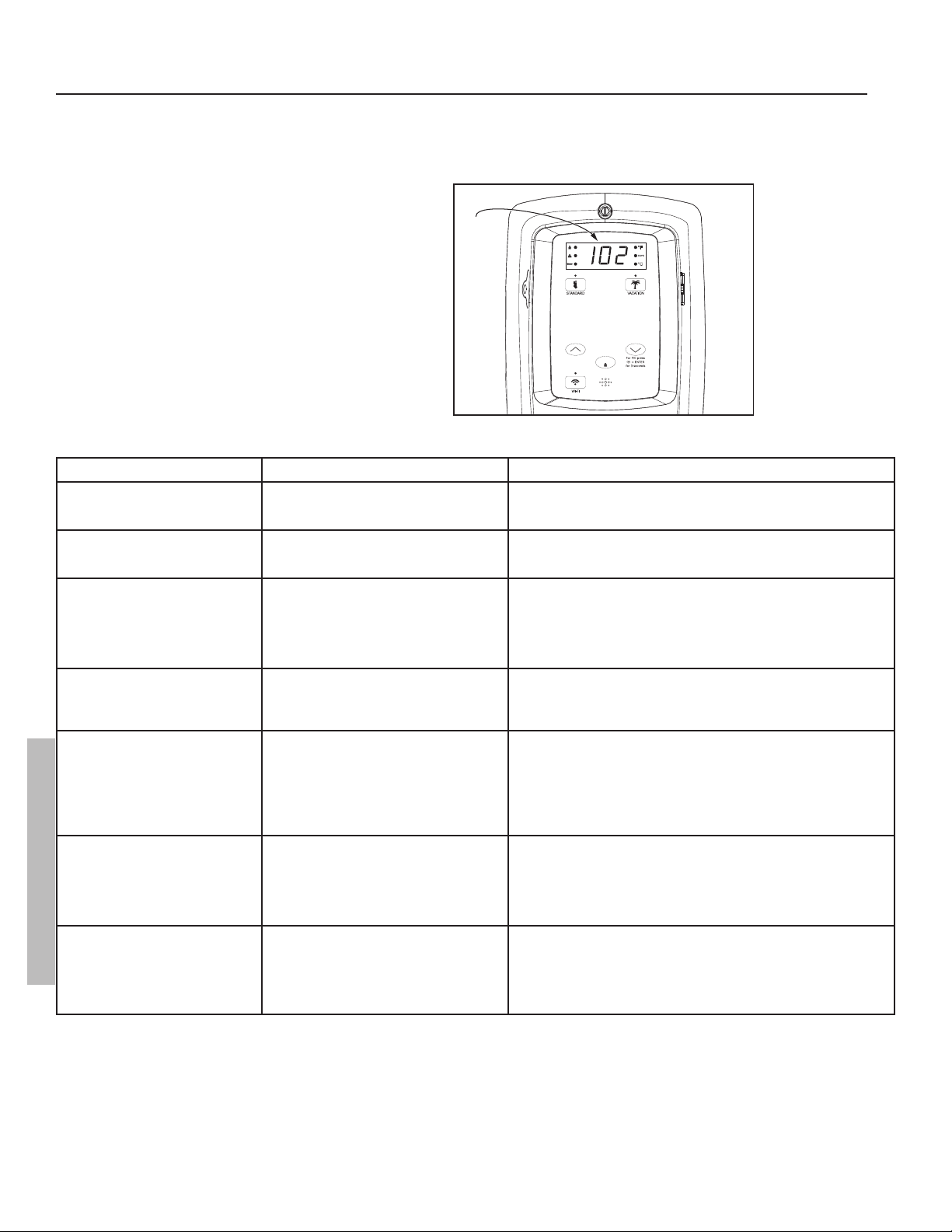
CONTROL ASSEMBLY DIAGNOSTIC CODE CHART
ERROR CODE INDICATES CORRECTIVE ACTION*
No Error Code Displayed
Not Enough Hot Water
High usage, plumbing leak, operating mode
adjustment.
1. Check for plumbing leak.
2. Adjust temperature; see scald warnings on heater and in manual.
3. Contact a qualified person to perform a volume test.
No Error Code Displayed
Water Too Hot
Water temperature set too high or grounded
element.
1. Reduce temperature setting.
2. Contact a qualified person to test for the grounded element and replace
if necessary.
No Error Code Displayed
No Hot Water
No power, control panel or thermostat 1. Turn off electrical power at breaker.
2. Unplug and reconnect 24 pin connector.
3. Turn on electrical power at breaker
4. Contact a qualified person to verify correct voltage to unit.
NOTICE: If the control assembly was not connected via WiFi the time will
need to be set.
001 with an alert Icon flashing.
(also flashing red LED and beeper.)
Dry-fire, electrical power on with the tank not
completely full of water.
1. Turn off electrical power at breaker. Add water, open a hot water faucet
to bleed all air until water flows without air bursts.
2. Turn on electrical power at breaker.
3. See “Important Safety Information” on page 4.
002 with an alert Icon flashing.
(also flashing red LED and beeper.)
Water temperature exceeded high limit. 1. Turn off electrical power at the breaker.
2. Press the reset button (see Figure 26).
3. Turn on electrical power at breaker.
4. If error returns contact a qualified technician to test for the grounded
element. Replace as needed.
5. If both elements test good, replace the thermostat.
6. Turn on electrical power at breaker.
003 with an alert Icon flashing.
(also flashing red LED and beeper.)
Upper thermistor sensor failure.
NOTICE: Upper thermistor sensor is part of
the thermostat.
1. Turn off electrical power at the breaker.
2. Check electrical connections at thermostat.
3. If there are no issues with the wiring, replace the thermostat.
4. Turn on electrical power at breaker.
NOTICE: The control assembly will go into Limp Mode until the failure is cor
rected. See page 22.
004 with an alert Icon flashing.
(also flashing red LED and beeper.)
Lower thermistor sensor failure.
NOTICE: Lower thermistor sensor is part of
the thermostat.
1. Turn off electrical power at the breaker.
2. Check electrical connections at thermostat.
3. If there are no issues with the wiring, replace the thermostat.
4. Turn on electrical power at breaker.
NOTICE: The control assembly will go into limp mode until the failure is cor
rected. See page 22.
IMPORTANT: Before attempting to adjust the ther-
mostat, read the “Important Safety Information”
section page 4.
If the instructions are not clear, contact a qualifi ed
person.
20 • Residen al Electronic Thermostat Electric Water Heater Use and Care Guide
TROUBLESHOOTING
°C
DAYS
ENTER
Error
Code
Figure 25 - Control Assembly Diagnostic Coding
TROUBLESHOOTING
Loading ...
Loading ...
Loading ...