
Loading ...
Loading ...
Loading ...
12
3.11 Other Functions
a. Lock
8SRQVWDUWXSRIWKHXQLWZLWKRXWPDOIXQFWLRQRUXQGHUWKH³2II´VWDWHRIWKHXQLWSUHVVŸDQGźat
the same time for 5s till the wired controller enters the Lock function. In this case, LCD displays
.
After that, repress these two buttons at the same time for 5s to quit this function.
Under the Lock state, any other button press won’t get any response.
b. Memory
0HPRU\VZLWFKRYHU8QGHUWKH³2II´VWDWHRIWKHXQLWSUHVV0RGHDQGŸDWWKHVDPHWLPHIRU
5s to switch memory states between memory on and memory off. When this function is activated,
Memory will be displayed. If this function is not set, the unit will be under the “Off” state after power
failure and then power recovery.
Memory recovery: If this function has been set for the wired controller, the wired controller after
power failure will resume its original running state upon power recovery. Memory contents: On/
Off,Mode, set temperature, set fan speed and Lock function.
4 Installation and Dismantlement
4.1 Connection of the Signal Line of the Wired Controller
Ɣ2SHQWKHFRYHURIWKHHOHFWULFFRQWUROER[RIWKHLQGRRUXQLW
Ɣ/HWWKHVLQJOHOLQHRIWKHZLUHGFRQWUROOHUWKURXJKWKHUXEEHUULQJ
Ɣ&RQQHFWWKHVLJQDOOLQHRIWKHZLUHGFRQWUROWRWKHSLQVRFNHWRIWKHLQGRRUXQLW3&%
Ɣ7LJKWHQWKHVLJQDOZLUHZLWKWLHV
Ɣ7KHFRPPXQLFDWLRQGLVWDQFHEHWZHHQWKHPDLQERDUGDQGWKHZLUHGFRQWUROOHUFDQEHXSWR
20 meters ( the standard distance is 8 meters)
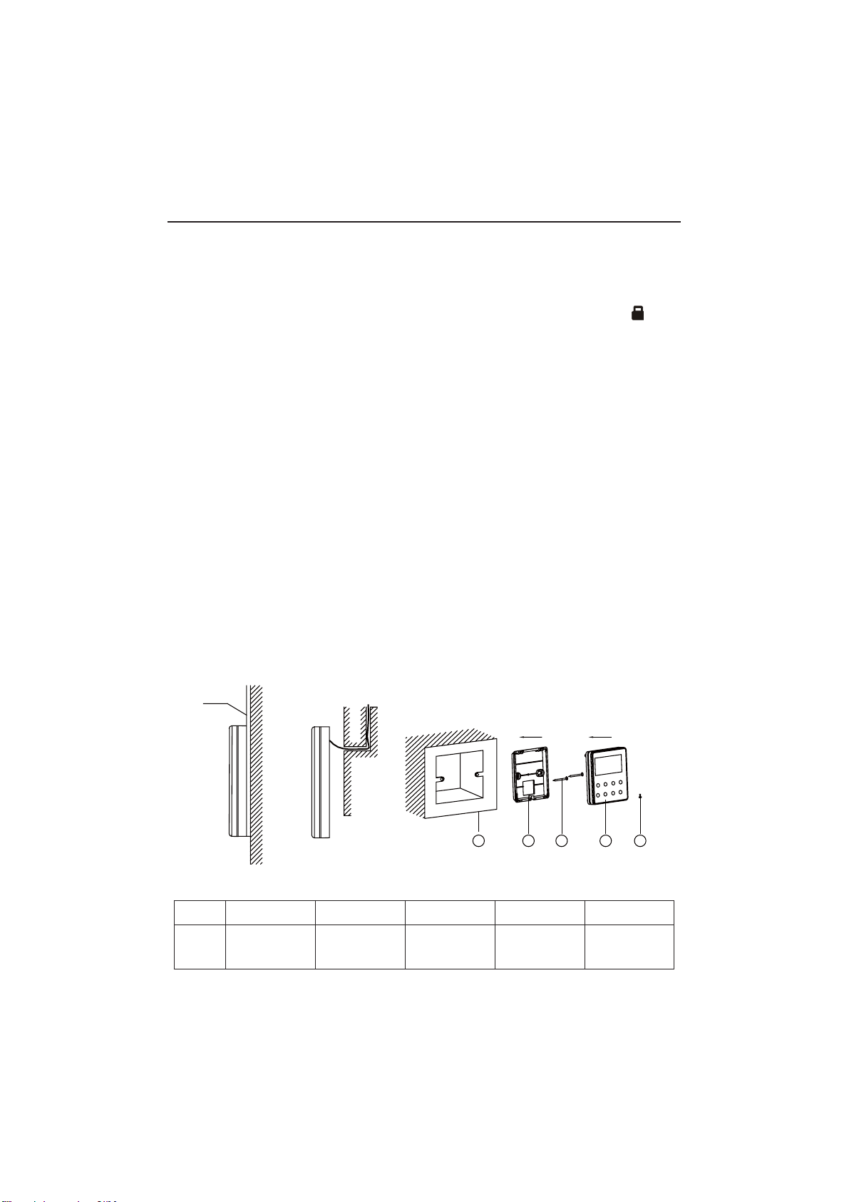
4.2 Installation of the Wired Controller
1
PVC Pipe
3 4 52
Fig.4.1 Accessories for the Installation of the Wired Controller
Table 4.1
No.12345
Name
Socket box
embedded
in the wall
*
Back-plate of
the Wired
Controller
Screw
M4X25
*
Front Panel
of the Wired
Controller
Screw
ST 2.9X6*
Wired Controller IS-TT850
*Not included
Loading ...
Loading ...
Loading ...