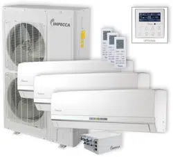

Owner's Manual
Split Type Wall-mounted Air Conditioner
Model:
ISMO-1821
Thank you for choosing our product.
For proper operation, please read and keep this manual carefully.
If you have lost the Owner’s Manual, please contact the local agent or
visit www.impecca.com for an electronic version.
v
. 1.1
CONTENTS
GENERAL INFORMATION
1
2
3
4
4
5
8
6
7
7
8
Technical Data
Electrical Connections
Installing The Outdoor Unit
Maintenance
Installation Dimension Diagram
Check After Installation
Bleeding
Conformity And Range
The Instructions Before Use
Name of Parts
Outdoor Unit Working Temperature Range
GENERAL
INSTALLER
INFORMATION
The products in this manual may be different with the rea one, according to different models, l
some models have displayer and some models without displayer, the position and shape of
the displayer please refer to the real one.
In line with the company
’s policy of continual product improvement, the aesthetic and dimensional
characteristics, technical data and accessories of this appliance may be changed without notice.
This appliance is not intended for use by persons (including children) with reduced physical,
sensory or mental capabilities, or lack of experience and knowledge, unless they have been
given supervision or instruction concerning use of the appliance by a person responsible for
their safety.
Children should be supervised to ensure that they do not play with the appliance.
This marking indicates that this product should not be disposed with other
household wastes throughout the EU. To prevent possible harm to the
environment or human health from uncontrolled waste disposal, recycle
it responsibly to promote the sustainable reuse of material resources. To
return your used device, please use the return and collection systems or
contact the retailer where the product was purchased. They can take this
product for environmental safe recycling.
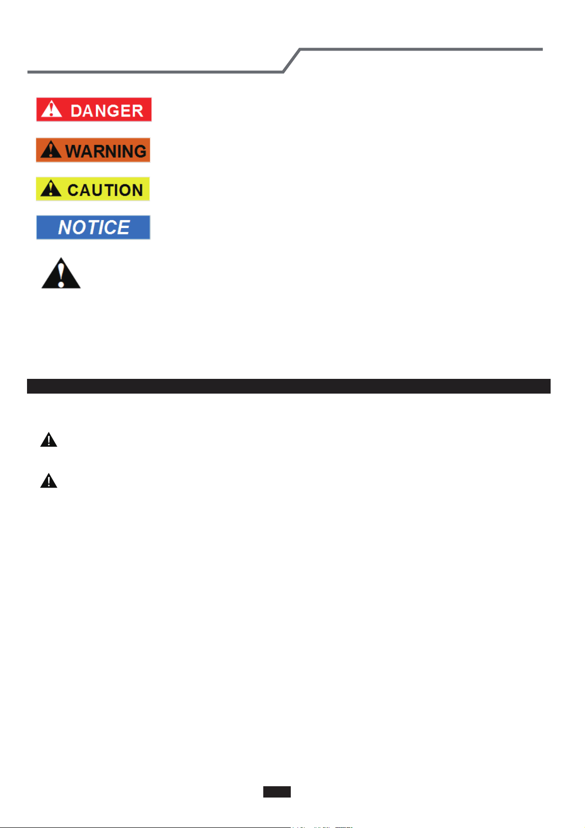
Explanation of Symbols
Indicates a hazardous situation that, if not avoided, will result in death
or serious injury.
Indicates a hazardous situation that, if not avoided, could result in death
or serious injury.
Indicates a hazardous situation that, if not avoided, may result in minor
or moderate injury.
Indicates important but not hazard-related information, used to indicate
risk of property damage.
Indicates a hazard that would be assigned a signal word
WARNING or CAUTION.
CONFORMITY AND RANGE
GENERAL INFORMATION
Please read this owner's manual carefully before operating the unit and keep it carefully for consultation.
Only use the air conditioner as instructed in this booklet. These instructions are not intended to
cover every possible condition and situation. As with any electrical household appliance, common sense
and caution are therefore always recommended for installation, operation and maintenance.
1
Instructions for installation and use of this product are provided by the manufacturer.
THE INSTRUCTIONS BEFORE USE GENERAL INFORMATION
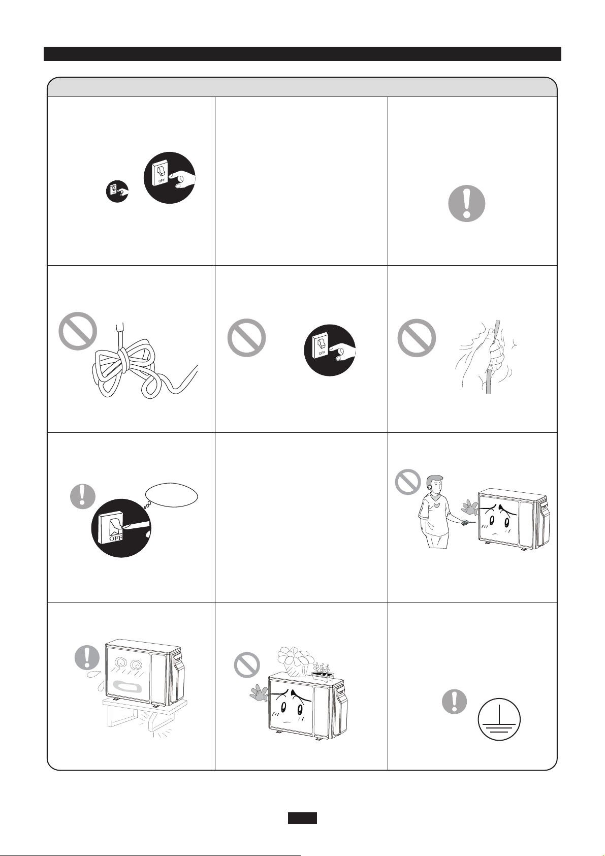
WARNING
When having a burning smell or
smoke,please turn off the power
supply and contact with the ser-
vice center.
If the abnormity still exists,the unit
may be damaged,and may cause
electric shock or fire.
Power must adopts the special
circuit to prevent fire.
Otherwise, it can cause electric
shock or fire.
Disconnect the power supply if
long putting the air conditioner
out of use.
Otherwise,the accumulated dusts
may cause overheating or fire.
Never damage the electric wire
or use the electric wire which is
not appointed.
Otherwise,it will cause overheating
or fire.
When cleaning,it is necessary
to stop driving and turn off the
power supply.
Cut off power supply
Otherwise,it may cause electric
shock or damage.
The power supply must adopt the
special circuit that with air switch
protection and assure it has enou-
gh capacity.The unit will be turned
on or off according to your requir-
ement automatically,please do not
turn on or turn off the unit freque-
ntly,otherwise disadvantage effect
may be caused to the unit.
Rated voltage of this air conditi-
oner 220-240V, 60Hz, The com-
pressor will vibrate sharply if the
voltage is too low, resulting in
damage to refrigerating system.
Electrical component are easy to
damage if the voltage is too high.
Don't attempt to repair the air
conditioner by yourself.
The wrong repair will lead to an
electric shock or fire,so you should
contact the service center to repair.
Don't step on the top of the
outdoor unit or place something
on it.
If it is damaged, it may lead to the
fall of the unit and cause the injury.
Please note whether the insta-
lled stand is firm enough or not.
Earthing: The unit must be reli-
ably earthed.The earthing cable
shall be connected to the spec-
ial earthing device in the const-
ruction.
As falling off the outdoor unit can be
dangerous.
Never cut off or damage power
cables and control wires. If the
power cable and signal control
wire were damaged, change
them by professional.
2
★ ★
★ ★
★
★
★ ★
★ ★
★
★
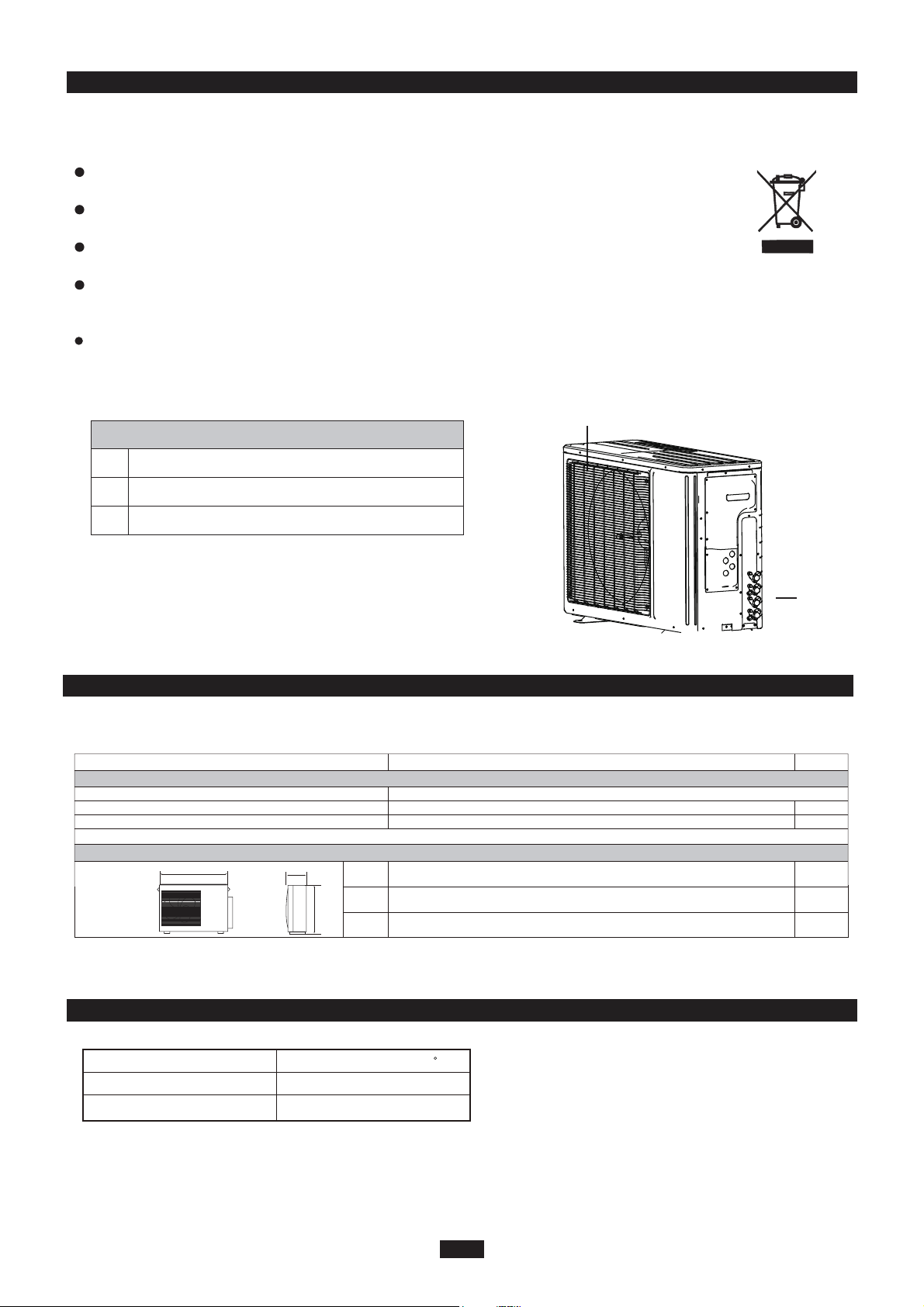
OUTDOOR UNIT
No. Description
1 Air outlet grille
2 Valve
Be sure to cut off the power supply before cleaning the air conditioner; otherwise electric
shock might happen.
Wetting of air conditioner may cause the risk of electric shock. Make sure not to wash
your air conditioner in any case.
This product must not be disposed together with the domestic waste.
This product has to be disposed at an authorized place for recycling of electrical and
electronic appliances.
Volatile liquids such as thinner or gasoline will cause damage to the appearance of air
conditioner. (Only use soft dry cloth moist cloth clean the air conditioner cabinet).
The temperature of refrigerant circuit will be high,please keep the interconnection cable
away from the copper tube.
Note: The above figures are only intended to a simple
diagram of the appliance and may not correspond to the
appearance of the units that have been purchased.
NAME OF PARTS
GENERAL INFORMATION
3
1
2
WARNING
P
L
H
Minimum power cord section
mm
mm
mm
L
P
H
Fuse or air switch
890
362
700
MODE
20
2.5
ISMO-1821
Electricity supply
Electrical data
208/230V,60HZ
mm
2
Size and clearance
TECHNICAL DATA GENERAL INFORMATION
OUTDOOR UNIT WORKING TEMPERATURE RANGE GENERAL INFORMATION
Maximum cooling
Maximum heating
48/-
27/-
OutdoorsideDB/WB(
c
)
INSTALLER
4
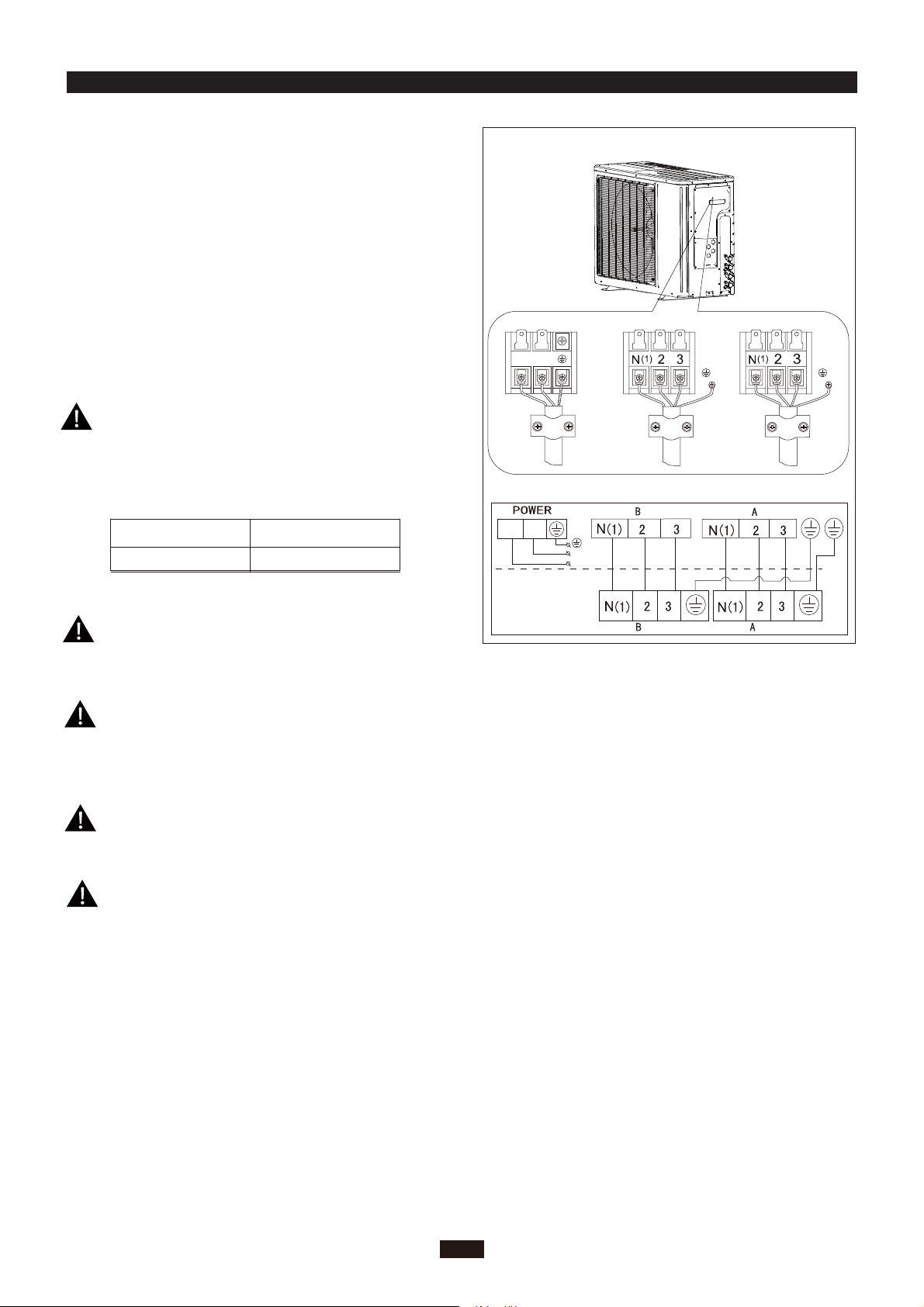
Wrong wire connection may cause malfunction of
some electric components.After fixing cable, ensure
that leads between connection to fixed point have
some space.
An all-pole disconnection switch having a contact
separation of at least 3mm in all pole should be
connected in fixed wiring.
2. Remove the cable clamp, connect the power connection
cable with the terminal at the row of connection and fix
the connection. The fitting line distributing must be
consistent with the indoor unit. terminal of line bank.
Wiring should meet that of indoor unit.
3. Fix power connection wire by wire clamp.
4. Ensure wire has been fixed well.
5. Install the handle.
unit (one screw).
The connection pipes and the connectiong wirings
of the unit A and unit B must be corresponding to
each other respective.
Note: the above figures are only intended to be a simple
diagram of the appliance and may not correspond to the
appearance of the units that have been purchased.
The appliance shall be installed in accordance with
national wiring regulations.
ELECTRICAL CONNECTIONS
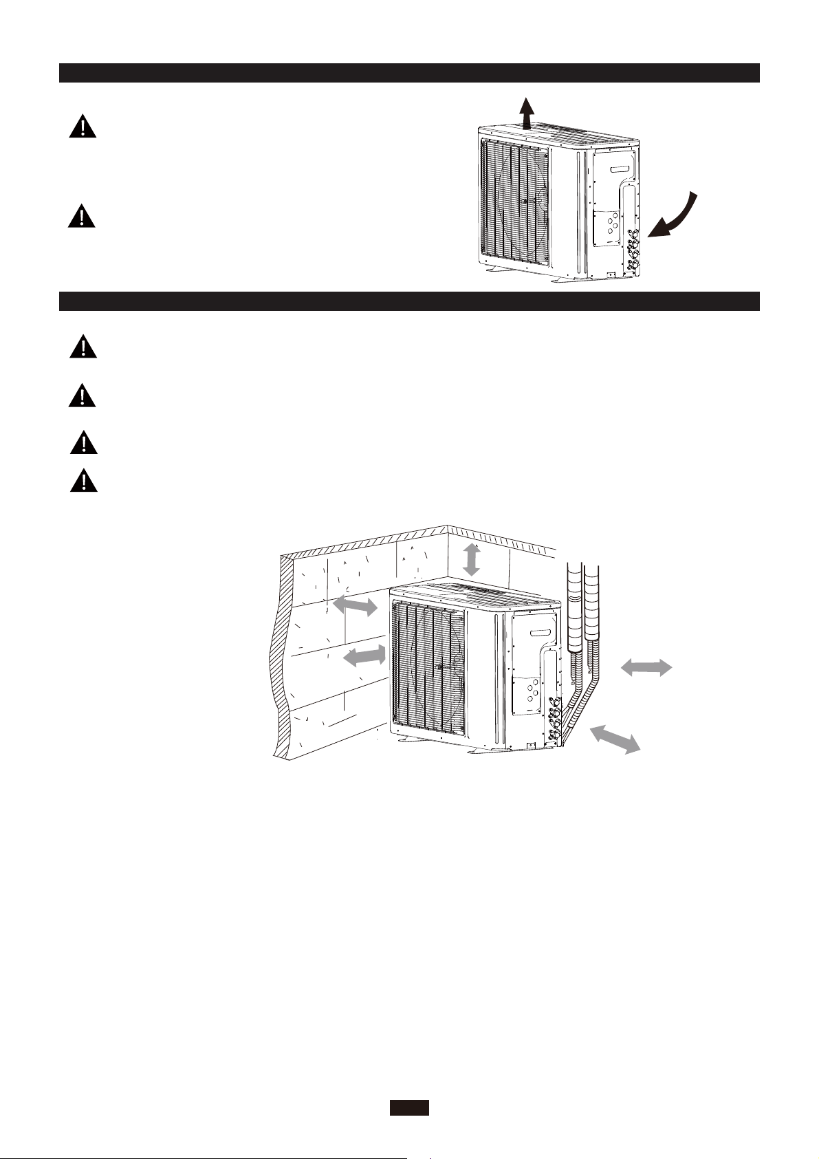
1. Remove the handle at the right side plate of the outdoor
L1
L2
To the power supply
To unit B
Power cord
To unit A
connecting
cable
L1
L2
L1 L2
connecting
cable
Including an air switch with suitable capacity,
please note the following table. Air switch
should be included magnet buckle and heating
buckle function, it can protect the circuit-short
and overload. (Caution: please do not use the
fuse only for protect the circuit)
ISMO-1821
25A
Air switch capacityAir-conditioner
INSTALLING THE OUTDOOR UNIT INSTALLER
BLEEDING INSTALLER
5
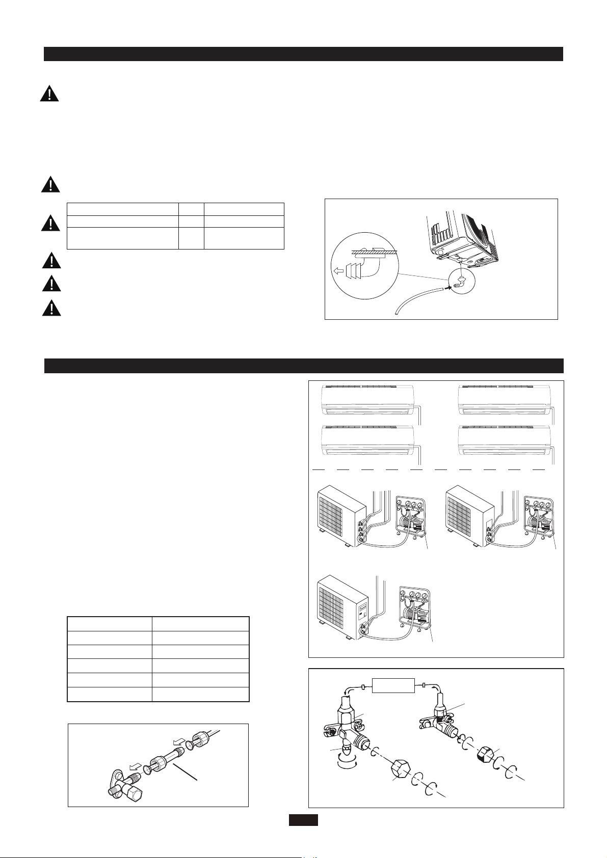
Do not install the outdoor unit in pits or air vents
Installing the pipes
Use suitable connecting pipes and equipment for
the refrigerant R410A.
Vacuum pump
Humid air left inside the refrigerant circuit can cause com-
pressor malfunction. After having connected the indoor
and outdoor units, bleed the air and humidity from the
refrigerant circuit using a vacuum pump.
(1) Unscrew and remove the caps from the 2-way and 3-
way valves.
(2) Unscrew and remove the cap from the service valve.
(3) Connect the vacuum pump hose to the service valve.
(4) Operate the vacuum pump for 10-15 minutes until an
absolute vacuum of 10 mm Hg has been reached.
(5) With the vacuum pump still in operation, close the
low-pressure knob on the vacuum pump coupling.
Stop the vacuum pump.
(6) Open the 2-way valve by 1/4 turn and then close it
after 10 seconds. Check all the joints for leaks using
liquid soap or an electronic leak device.
(7) Turn the body of the 2-way and 3-way valves. Discon-
nect the vacuum pump hose.
(8) Replace and tighten all the caps on the valves.
Vacuum pump Vacuum pump
Location
Twisting moment (N.m)
35-40
60-65
45-50
70-75
Φ12
Φ19
Diameter (mm)
Φ9.52
Φ16
15-20Φ6
18K unit need to be installed the indoor unit
Caution: Installation Must be Performed in Accordance
with the NEC/CEC by Authorized Personnel Only.
conversion joint
18K MODE:
●
INDOOR
UNIT
Connect to the
indoor unit
Refrigerant fluid di
rection of fiow
3-way valve
2-way valve
inlet
(2)Turn
(8) Secure
(7)Turn to open fully
(2)Turn
(8) Secure
(6) Open by 1/4 turn
(7)Turn to open fully
(2)Turn
(8) Secure
V
alve cap
Valve cap
Service
The refrigerant pipes must not exceed the maximum
heights 5m(1821K).
Wrap all the refrigerant pipes and joints.
Tighten the connections using two wrenches wor-
king in opposite directions.
Use bolts to secure the unit to a flat, solid floor.
When mounting the unit on a wall or the roof, make
sure the support is firmly secured so that it cannot
move in the event of intense vibrations or a strong
wind.
Install the drain fitting and the drain hose
(for model with heat pump only)
Condensation is produced and flows from the out-
door unit when the appliance is operating in the
heating mode. In order not to disturb neighbours
and to respect the environment,install a drain fitting
and a drain hose to channel the condensate water.
Install the drain fitting and rubber washer on the
outdoor unit chassis and connect a drain hose to it
as shown in the figure.
Model(m) 1821x2
Max. connection pipe length
20
Max. connection pipe length
(Simple one indoor unit)
10
Use suitable instruments for the refrigerant R410A.
Do not use mineral oils to clean the unit.
Ensure that the recommende dspace is left around the appliance.
The installation must be done by trained and qualified service personnel with reliability according to this
manual.
Contact service center before installation to avoid the malfunction due to unprofessional installation.
When picking up and moving the units, you must be guidedby trained and qualified person.
Do not use any other refrigerant than R410A.
●
MAINTENANCE INSTALLER
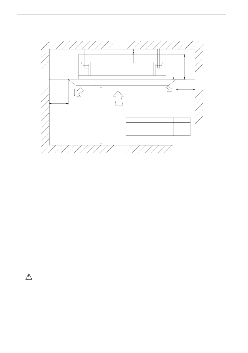
INSTALLATION DIMENSION DIAGRAM INSTALLER
6
30cm
or above
Space to the cover
200cm
50cm
30cm
(Air inlet side)
or above
or above
Space to the wall
(Air outlet side)
or above
or more
Space to the cover
50c
m
CHECK AFTER INSTALLATION INSTALLER
7
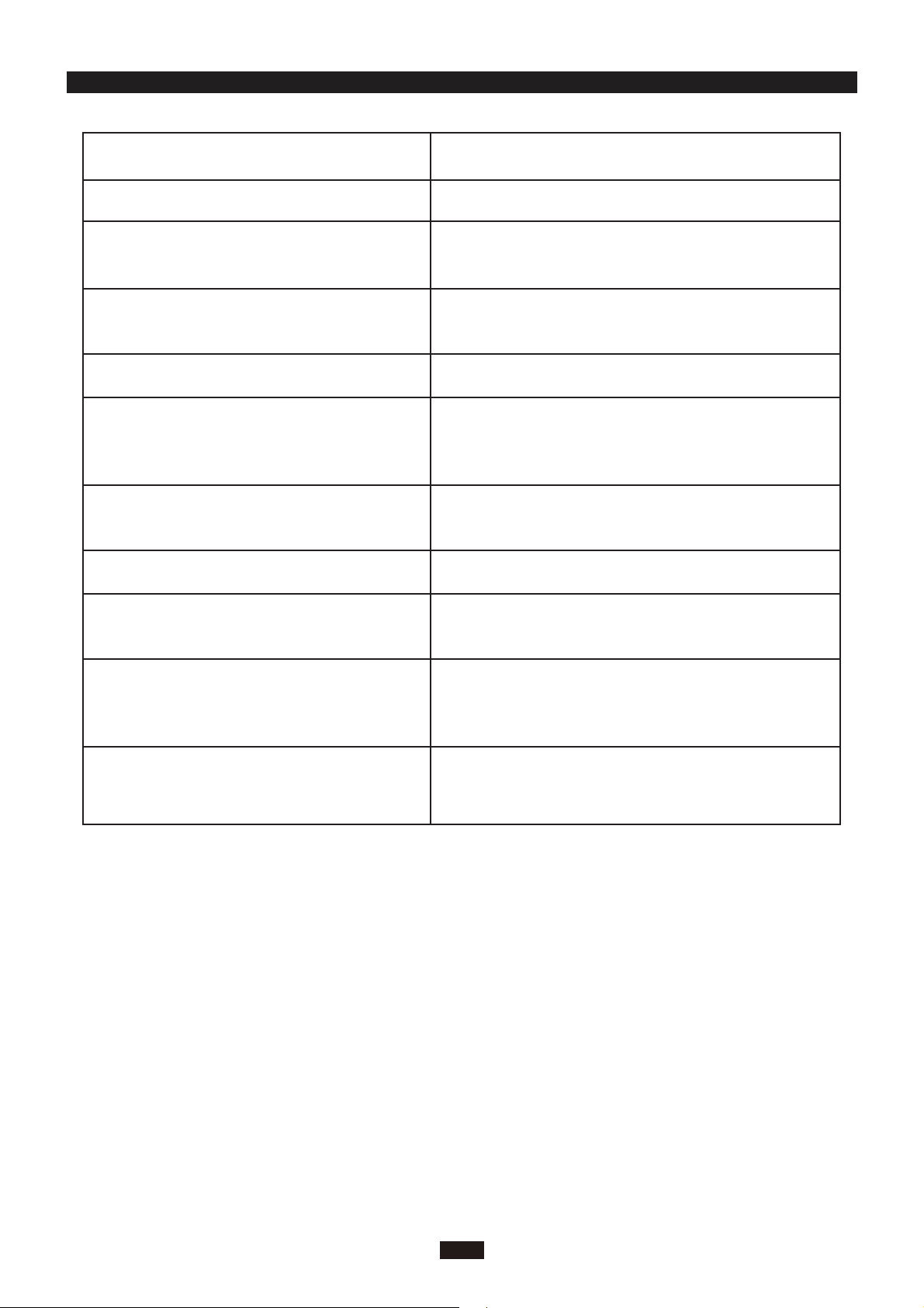
Check Items
Is the installation reliable?
Has the gas leakage been checked?
Is the thermal insulation of the unit
sufficient?
Is the drainage smooth?
Does the power supply voltage accord
with the rated voltage specified on the
nameplate?
Are the lines and pipelines correctly
installed?
Are the models of lines in conformity
with requirements?
Are there any obstacles near the air
inlet and outlet of the indoor and out-
door units?
Have the length of refrigerating pipe
and refrigerant charge amount been
recorded?
Has the unit been safely grounded?
Problems Owing to Improper Installation
The unit may drop, vibrate or make noises
May cause unsatisfactory cooling (heating)
effect
May cause condensation and water dropping
May cause condensation and water dropping
The unit may bread down or the components
may be burned out
The unit may bread down or the components
may be burned out
The unit may bread down or the components
may be burned out
The unit may bread down or the components
may be burned out
It is not easy to decide the charge amount
of refrigerant.
Risk of electrical leakage

CUSTOMER S
UPPORT
Before contacting customer support, please see the troubleshooting guide above.
Visit our website to contact us, find answers to Frequently Asked Questions, and for other
resources which may include an updated version of this user's guide.
WWW.IMPECCA.COM
If you wish to contact us by phone, please be sure to have your model number and serial
number ready and call us between 9:00am and 6:00pm ET, at +1 866-954-4440.
Keep tabs on Impecca's newest innovations & enter contests via our social network feeds:
www.facebook.com/Impecca/
www.instagram.com/impecca/
@impeccausa


© 2016 Impecca, a division of LT Inc., Wilkes Barre, PA.

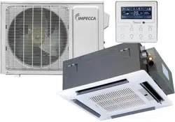
Flex Series R410A GMV Multi
VFR System-Indoor Unit (For
North America) Compact Panel
Cassette Type Indoor Unit
Thank you for choosing Air Conditioners, please read this owner’s manual carefully before operation
and retain it for future reference. If you have lost the Owner’s Manual, please contact the local agent or
visit www.Impecca.com for an electronic version.
Impecca reserves the right to interpret this manual which will be subject to any change due to
product
improvement without further notice.
Impecca reserves the final right to interpret this manual.
Owner's Manual
Air Conditioners
Model:
ISMI-C15
v. 1.1

User Notice
◆
When operating, the entire capacity of the cooperating indoor unit should be not larger
than 150% of outdoor unit. Otherwise, it will cause the shortage of cooling (heating) capacity.
◆
A Breaker(or fuse) need to be installed in every indoor unit, and the capacity should
in according with indoor unit’s electrical parameter; all the indoor units are required to be
centralized controlled by a total Switch, this Switch can cut off the electric power supply in
case of emergency. The Breaker(or fuse) on each indoor units have the function of short
circuit prevention and abnormal overload avoiding, it should be connected in normal situation.
The total switch controlling the power supply of all the indoor units. Before clearing and
maintenance job being carried out to the indoor units, it is very important to turn off the total
power supply switch.
◆
In order to turn on the units successfully, the main power switch should be opened 8
hours before the operation.
◆
After receiving the turn off signal, every indoor unit will continue to work for 20-70sec to
make use of the rest cool air or the rest heat air in the heat exchanger, while preparing for the
next operation. And this is normal.
◆
When the selected operating mode of the indoor unit are clash with the operating
mode of the outdoor unit, the malfunction light will blink after 5s on the indoor unit or remote
controller showing that the operation clash, then the indoor unit will stop. At this time, change
the operation mode of the indoor unit to the one that would not clash with the outdoor operating
mode to make the operation normal. The cooling mode is not clash with the dry mode, while
the fan mode is not clash with any mode.
◆
The appliance shall not be installed in the laundry.
◆
An all-pole disconnection switch having a contact separation of at least 3mm in all poles
should be connected in xed wiring.
◆
Information regarding transport/storage temperature (-25-55°C) is missing.
◆
Main switch provided by end user: main switch handle should be black or gray, it can be
locked in “OFF” position with padlock.
◆
The main disconnection device should be explained in user manual and the height
should be recommended at 0.6-1.7m. over current protection is required(UL 1995,CSA C22.2).
◆
The cooling range of the unit is the outdoor environment temp.-5~48°C DB, the heating
range of the unit( only for the heat pump type unit) is the outdoor environment temp. -15~27°C
WB.
This product must not be disposed together with the domestic waste. This product
has to be disposed at an authorized place for recycling of electrical and electronic
appliances.
Thank you for your selecting of Impecca air conditioner, please read this usage
and install instruction carefully and keep it well in order to use this unit correctly.

Contents
1 Safety Information .....................................................................................1
2 Install of The Compact Panel Cassette Type Indoor Unit ..........................2
2.1 Schematic diagram of installation spaces ......................................................... 2
2.2 Select install location of the indoor unit ............................................................. 2
2.3 Important notice ................................................................................................ 3
2.4 Dimension of ceiling opening and location of the hoisting screw (M10) ............ 3
2.5 Main body of hoisting air conditioner ................................................................. 3
2.6 Connection of the refrigerant pipe ..................................................................... 4
2.7 Drainage hose ................................................................................................... 5
2.8 Electrical wiring ................................................................................................. 7
2.9 Install the panel ................................................................................................. 8
3
Constitutes and Names of Parts of Compact Panel Cassette Type Indoor Unit
.. 10
4 Working Temperature Range ................................................................... 11
5 Malfunction Debarring .............................................................................12
5.1 Check the following items before contacting maintenance center .................. 12
5.2 Instruction ........................................................................................................ 13
5.3 The following circumstance are not malfunction ............................................. 13
5.4 After-sales Service .......................................................................................... 13
6 Maintenance Method ............................................................................... 14
6.1 Cleaning air lter ............................................................................................. 14
6.2 Clean air inlet grille .......................................................................................... 15
6.3 Install and change of air purier ...................................................................... 15
6.4 Clean Outlet vent and Surface Panel .............................................................. 16
6.5 Maintenance before or after usage season ..................................................... 16
Safety Information
1
1 Safety Information
Please read this manual carefully before use this unit, and operate it correctly according to the
guide in this manual.
Please take specially note to the meaning of these two marks:
Warning!: This mark means that it may cause casualty or badly heart if the operation is
incorrect.
Note!: This mark means that it may cause casualty or property loss if the operation is
incorrect.
Warning:
◆
Do not adopt fuse with unsuitable capacity or adopt iron thread instead of fuse, otherwise
malfunction or re may happened.
◆
Cut down the main power switch immediately if malfunction (such as smell the burning odor
etc.) happened.
◆
Maintain ventilation to prevent oxygen leakage in room.
◆
Don’t insert nger or stick like things into discharge vent or outlet grill.
◆
Please make sure that the unit is installed in the place that can bear the weight of it
adequately. If the place is not strong enough, the air conditioner may drop and cause casualty event.
◆
Don’t spray or smear any oil paint or insecticide on the surface of unit, otherwise, re may be
leaded.
(1). Do not ret the conditioner. Please contact the agency or prefect ional personnel to repair or
move the conditioner.
An all-pole disconnection switch having a contact separation of at least 3mm in all poles
should be connected in xed wiring.
Note!:
◆
Please check and make sure that the cord, drainage pipe and tubes are connected in the
correct way to prevent leakage of water, refrigerant, electric shock or re.
◆
The main power must connectable to the earth in order to assure the conditioner earthing
effectively and to prevent electric shock. Please don’t connect the earthing line with the gas pipe,
water pipe, lightening rod or the connecting line of telephone.
◆
The air conditioner should be turned off at least after 5 mins’ operation; otherwise it would
affect the duration of the unit.
◆
Don’t let the children operate the air conditioner.
◆
Please don’t operate the unit by wet hand.
◆
Please turn off the main power of the unit before cleaning the conditioner or change the lter.
◆
Please cut off the main power if the conditioner will be used for a long time.
Install of The Compact Panel Cassette Type Indoor Unit
2
2 Install of The Compact Panel Cassette Type Indoor Unit
2.1 Schematic diagram of installation spaces
≥2500
≥1500
≥1500
Model
H
260
unit:mm
>20
Wall
surface
Wall
surface
Wall
surface
Ground
surface
H
ISMI-C15
Fig.1
2.2 Select install location of the indoor unit
(1). Obstruct should put away from the intake or outlet vent of the indoor unit so that the airow
can be blown though all the room.
(2). Make sure that the installation had accord with the requirement of the schematic diagram of
installation spaces.
(3). Select the place where can stand 4 times of the weight of the indoor unit and would not
increase the operating noise and oscillate.
(4). The horizontally of the installation place should be guaranteed.
(5). Select the place where easy drain condensated coagulated water, and easy connect with
outdoor unit.
(6). Make sure that there are enough space for care and maintenance. Make sure that the
weight between the indoor unit and ground is above 2500mm.
(7). When installing the steeve bolt, check if the install place can stand the weight 4 times of the
unit’s. If not, reinforce before installation. (Refer to the install cardboard and nd where should be
reinforced)
Note!
There will be lots of lampblack and dust stick on the acentric, heat exchanger and water pump
in dining room and kitchen, which would reduce the capacity of heat exchanger, lead water leakage
and abnormal operation of the water pump. The following treatment should be taken under this
circumstance:
(8). Ensure that the smoke trap above cooker has enough capacity to obviate lampblack to
prevent the indraft of the lampblack by the air conditioner.
(9). Keep the air conditioner far from the kitchen so that the lampblack would not be indraft by
the air conditioner.
Install of The Compact Panel Cassette Type Indoor Unit
3
2.3 Important notice
◆
To guarantee the good performance, the unit must be installed by professional personnel
according with this instruction.
◆ Please contact the local Impecca special
nominated repair department before installation.
Any
malfunction caused by the unit that is installed by the department that is not special nominated
by Impecca would not deal with on time by the inconvenience of the business contact.
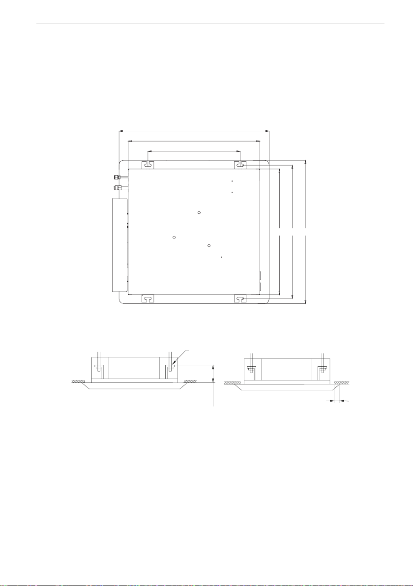
2.4 Dimension of ceiling opening and location of the hoisting screw (M10)
650
570
400
570 604 650
Fig.2 Install dimension of mode
◆
The drilling of holes in the ceiling must be done by the professional personnel.
Ceiling
Installation stands for main body of the unit
(160)
Above 20
Fig.3
Notes: The dimension for the ceiling openings with * marks can be as large as 610mm. But the
overlapping sections of the ceiling and the decorated surface boards should be maintained at no
less than 20mm.
2.5 Main body of hoisting air conditioner
(1). The primary step for install the indoor unit.
◆
When attach the hoisting stand on hoisting screw, do use nut and gasket individually at the
upper and lower of the hoisting stand to x it. The use of gasket anchor board can prevent gasket
break off.
(2). Use install cardboard.
◆
Please refer to the install cardboard about the dimension of ceiling opening.
◆
The central mark of the ceiling opening is marked on the install cardboard.
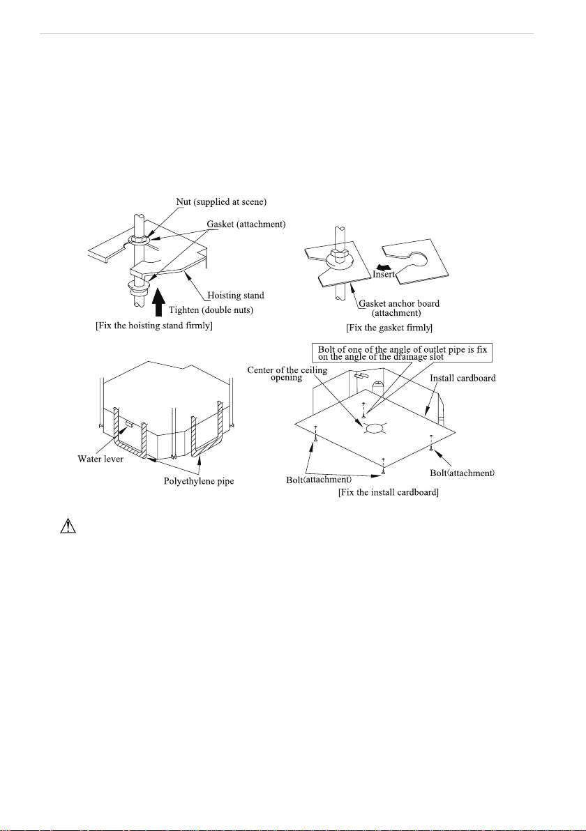
Install of The Compact Panel Cassette Type Indoor Unit
4
◆
Install the install cardboard on the unit by bolt (3 piece), and x the angle of the drainage pipe
at the outlet vent by bolt.
(3). Adjust the unit to the suitable install place. (Refer to the g.3)
(4). Check if the unit is horizontal.
◆
Inner drainage pump and bobber switch are included in the indoor unit, check if 4 angle of
every unit are horizontal by water lever. (If the unit is slant toward the opposite of the coagulate
water ow, there may be malfunction of the bobber switch and lead water drop.)
(5). Backout the gasket anchor board used to prevent gasket break off and tighten the nut on it.
(6). Backout the install cardboard.
Fig.4
Note!: Please do tighten the nuts and bolts to prevent air conditioner break off.
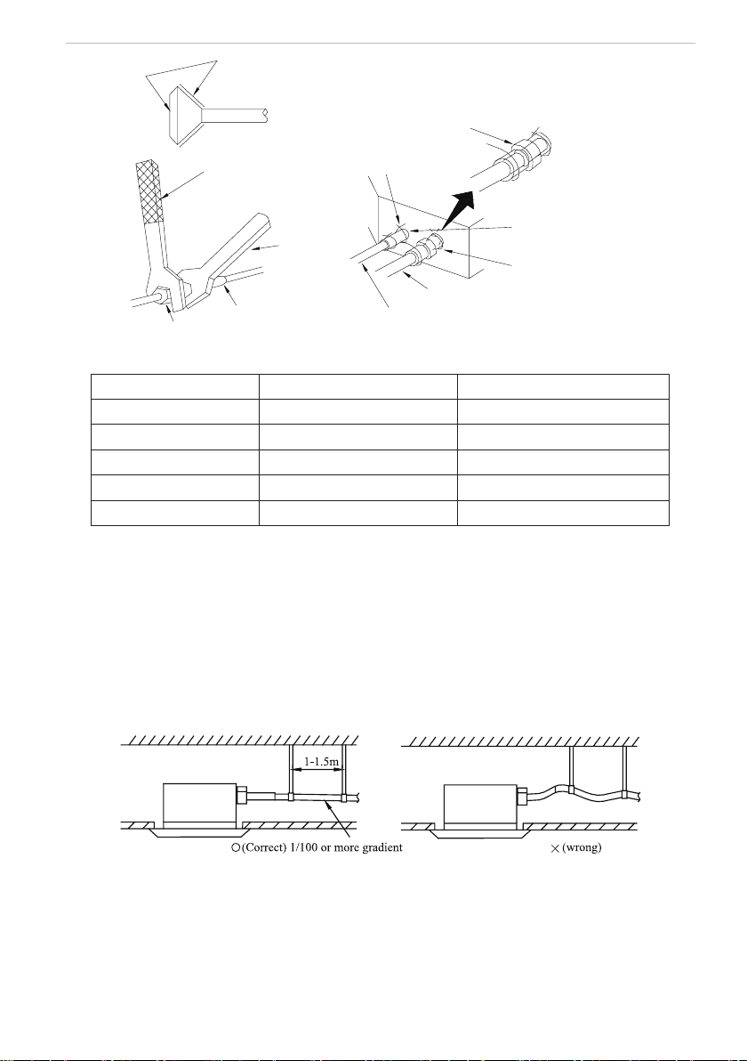
2.6 Connection of the refrigerant pipe
◆
When connect the pipe to the unit or backout it from the unit, please do use both spanner and
torque wrench. as shown in g.5.
◆
When connect, smear both inside and outside of the are nut with freeze motor oil, screw it
by hand and then tighten it with spanner.
◆
Refer to form 1 to check if the wrench had been tightened (too tight would mangle the nut
and lead leakage).
◆
Examine the connection pipe to see if it had gas leakage, then take the treatment of heat
insulation, as shown in the g.5.
◆
Only use median sponge to entwine the wiring interface of the gas pipe and heat preservation
sheath of the gas collection tube.
Install of The Compact Panel Cassette Type Indoor Unit
5
Smear freeze motoroil
here
Spanner
Thread fasten(x4)
Median sponge (attachment)
(entwine the wiring interface
with seal mat)
Gas collection tube
Liquid inlet tube
Heat preservation
sheath of liquid inlet
tube (attachment) (for
liquid tube)
Heat preservation
sheath of gas collection
tube (attachment)(for
gas tube)
Flare nut
Wiring interface
Torque wrench
Fig.5
Form 1: The tightening torque needed for tightening nut
Diameter
(
Inch
)
Surface thickness
(
mm
)
Tightening torque (N
·
m)
φ1/4’’
≥
0.5 15-30 (N
·
m)
φ3/8’’
≥
0.71 30-40 (N
·
m)
φ1/2’’
≥
1 45-50 (N
·
·m)
φ5/8’’
≥
1 60-65 (N
·
m)
φ3/4’’
≥
1 70-75 (N
·
·m)
2.7 Drainage hose
(1). Install the drain hose
◆
The diameter of the drain hose should be equal or bigger than the connection pipe’s. ( The
diameter of polythene pipe: Outer diameter 25mm Surface thickness
≥
1.5mm)
◆
Drain hose should be short and drooping gradient should at less 1/100 to prevent the
formation of air bubble.
◆
If drain hose cannot has enough drooping gradient, drain raising pipe should be added.
◆
To prevent bent of the drain hose, the distance between hoisting stand should is 1 to 1.5m.
Fig.6
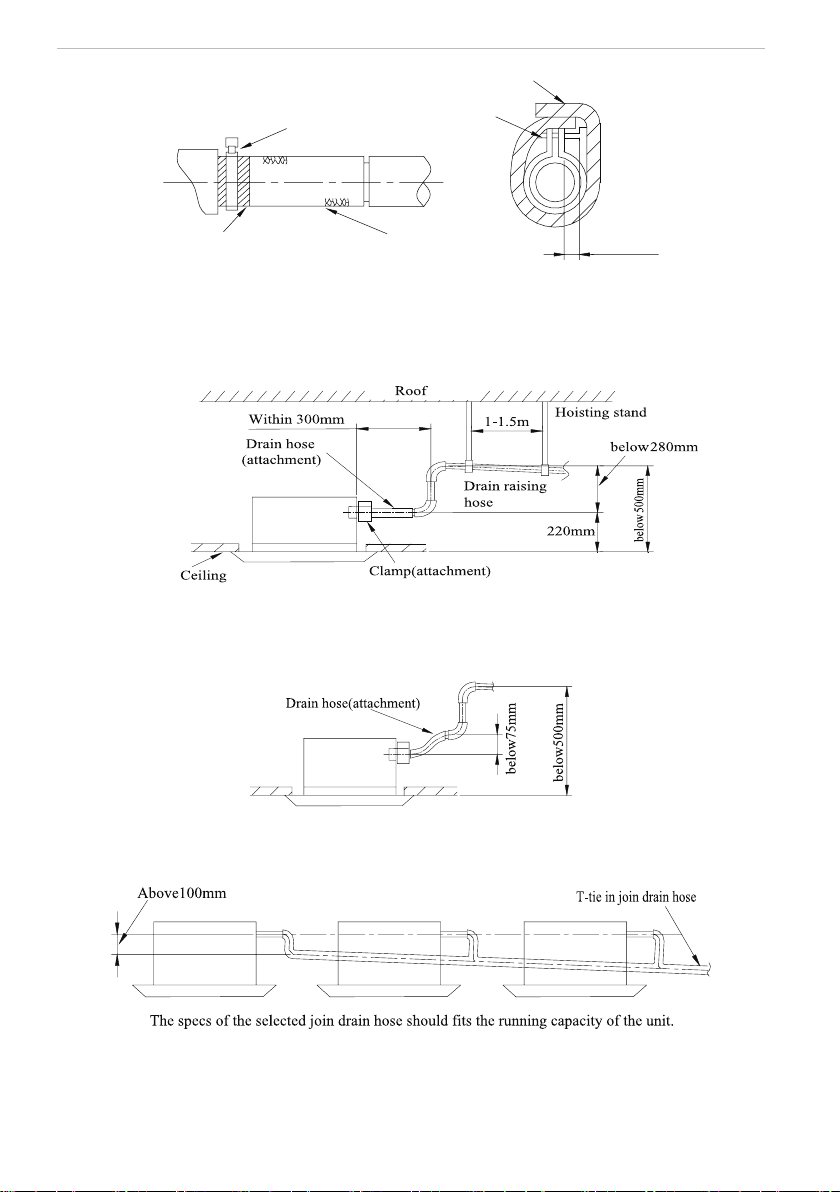
◆
Use the drain hose and clamp attached. Insert the drain hose to the drain vent, and then
tighten the clamp.
◆
Entwine the big sponge on the clamp of drain hose to insulate heat.
◆
Heat insulation should be done to indoor drain hose.
Install of The Compact Panel Cassette Type Indoor Unit
6
Sponge(attachment)
Clamp(attachment)
Below 4mm
Clamp
Drain hose
Sponge (gray)
Fig.7
Drain stepup pipe note
◆
The install height of the drain raising pipe should less than 280mm.
◆
The drain raising pipe should form a right angle with the unit, and distance to unit should not
beyond 300mm.
Fig.8
Instruction
◆
The slant gradient of the attached drain hose should be within 75mm so that the drain hole
doesn’t has to endure the unnecessary outside force.
Fig.9
◆
Please install the drain hose according to the following process if several drain hoses join
together.
Fig.10
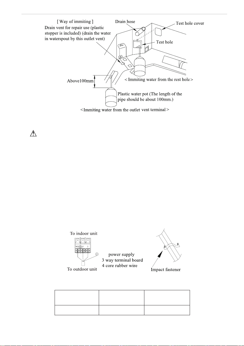
(2). Check the smoothness of drain after installation.
◆
Check the drain state by immitting 600cc water slowly from the outlet vent or test hole.
◆
Check the drain in the state of refrigerating after installation of the electric circuit.
Install of The Compact Panel Cassette Type Indoor Unit
7
Fig.11
2.8 Electrical wiring
Note:The power of the entire indoor unit must be connected in outdoor unit.
◆
About the electrical wiring, please see the circuit diagram attached with the unit.
◆
All the installation of electrical wiring must be done by professional personnel.
◆
Please do take the earthing treatment.
Wiring method of connection unit and controller
◆
Connection wiring (communication):
①
Open electric box cover, drag the wiring (communication)from the rubber plug A, and impact
them well individually by impact fastener.
②
Wiring according to the indoor side circuit diagram.
◆
Fix the impact fastener after connection.
◆
Entwine the small sponge on the electric wire( do entwine it to prevent condensation).
◆
Impact tightly by impact fastener after connection and then t on the electric box.
◆
Connect the 3 cord rubber wire to the counter terminal of the 3 way terminal board.
The power cord reference Power cord standard recommending table
Fig.12
Power cord standard recommending table
Power Supply
(V, Ph, Hz)
Min. Sectional Area of
Earth Wire(AWG)
Min. Sectional Area of
Power Cord(AWG)
208~203V-1Ph-60Hz
UL1015 AWG 18*1 UL1015 AWG 18*3
Install of The Compact Panel Cassette Type Indoor Unit
8
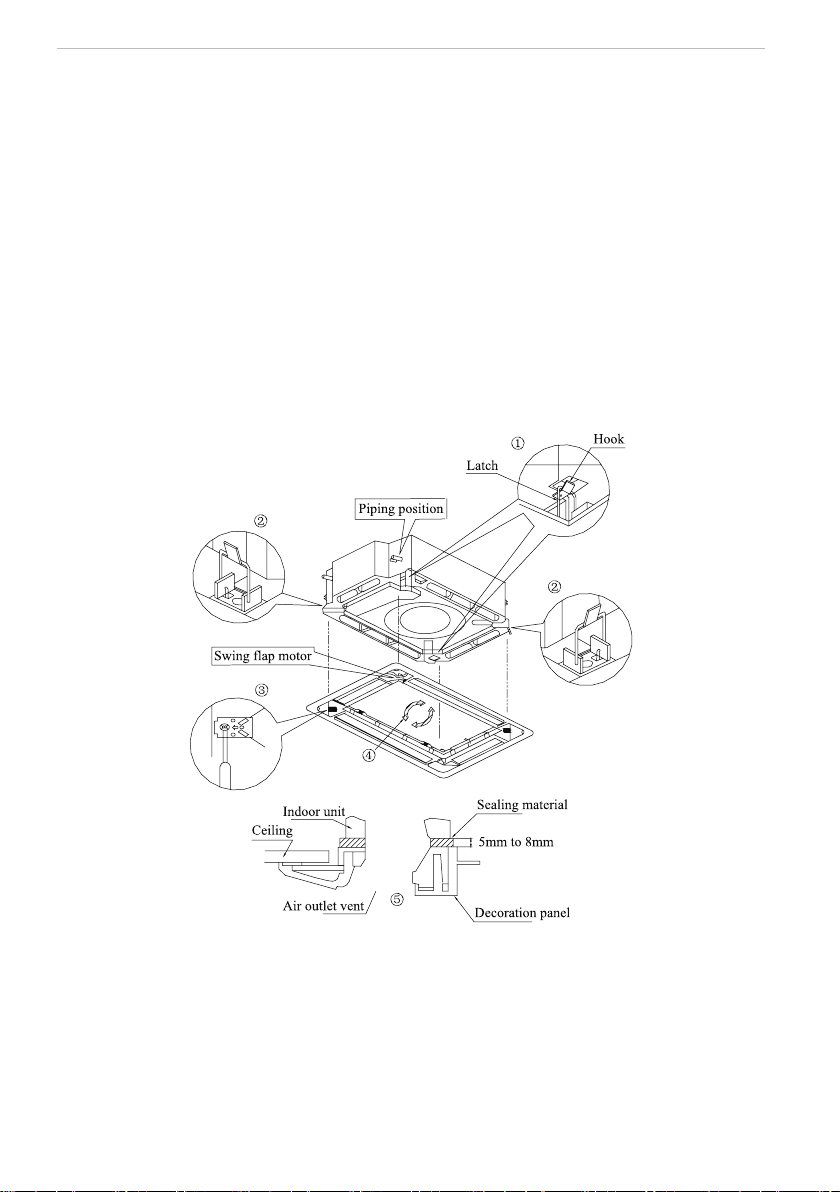
2.9 Install the panel
(1). Set the panel to the indoor unit body by matching the position of the swing ap motor of the
panel to the piping position of the panel to the piping position of the indoor unit as shown by g.13.
(2). Install the panel
① .
Install the panel on the indoor unit temporarily. When install, hang the latch on the hook
that is located on the opposite side of the swing ap on the panel of the indoor unit. (2
positions)
② .
Hang the remaining 2 latches to the hooks on the sides of the indoor unit.(Be careful not to
let the swing motor lead wire get caught in the sealing material.)
③ .
Screw the 4 hexagon head screws under the latches in about 15mm. (The panel would
rise)
④ .
Adjust the panel by turning it toward the direction pointed by the arrow as shown in g.13,
so that the adjust board connect the ceiling well.
⑤ .
Tighten the screws until the thickness of the sealing material between panel and indoor
unit reduced to 5-8mm.
Fig.13
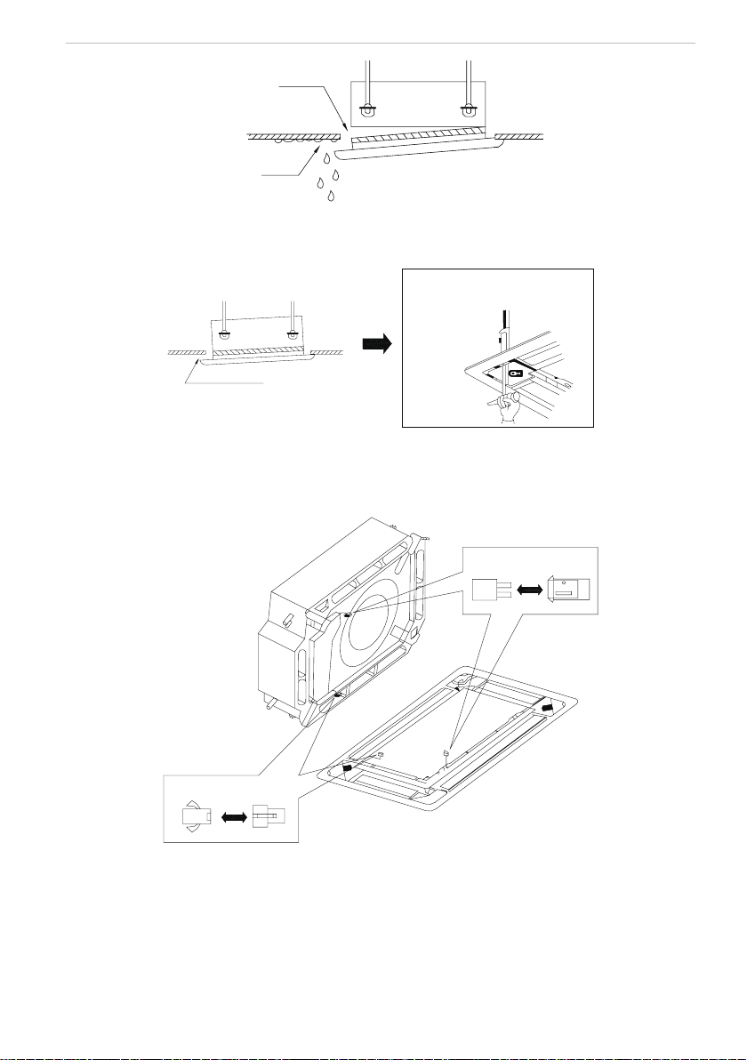
Notes:
① .
Improper screwing of the screws may cause the troubles shown in g.14.
Install of The Compact Panel Cassette Type Indoor Unit
9
Air leak
Air leak from ceiling
Water condensatation, water drop
Fig.14
② .
If gap still exist between ceiling and decoration panel after tightening the screws, readjust
the height of the indoor unit. (As shown in g.15)
If the raising lever and drain hose are
not affect, can adjust the height of
indoor unit by the hole on the corner
of panel.
Gaps are not allowed
Fig.15
※
After xing, be sure no gap left between the ceiling and the panel.
③ .
Wiring of the decoration panel (Fig.16)
Connect the joints for swing ap motor lead wire (at 2 places) installed on the panel.
At body At pane
At body At pane
Fig.16
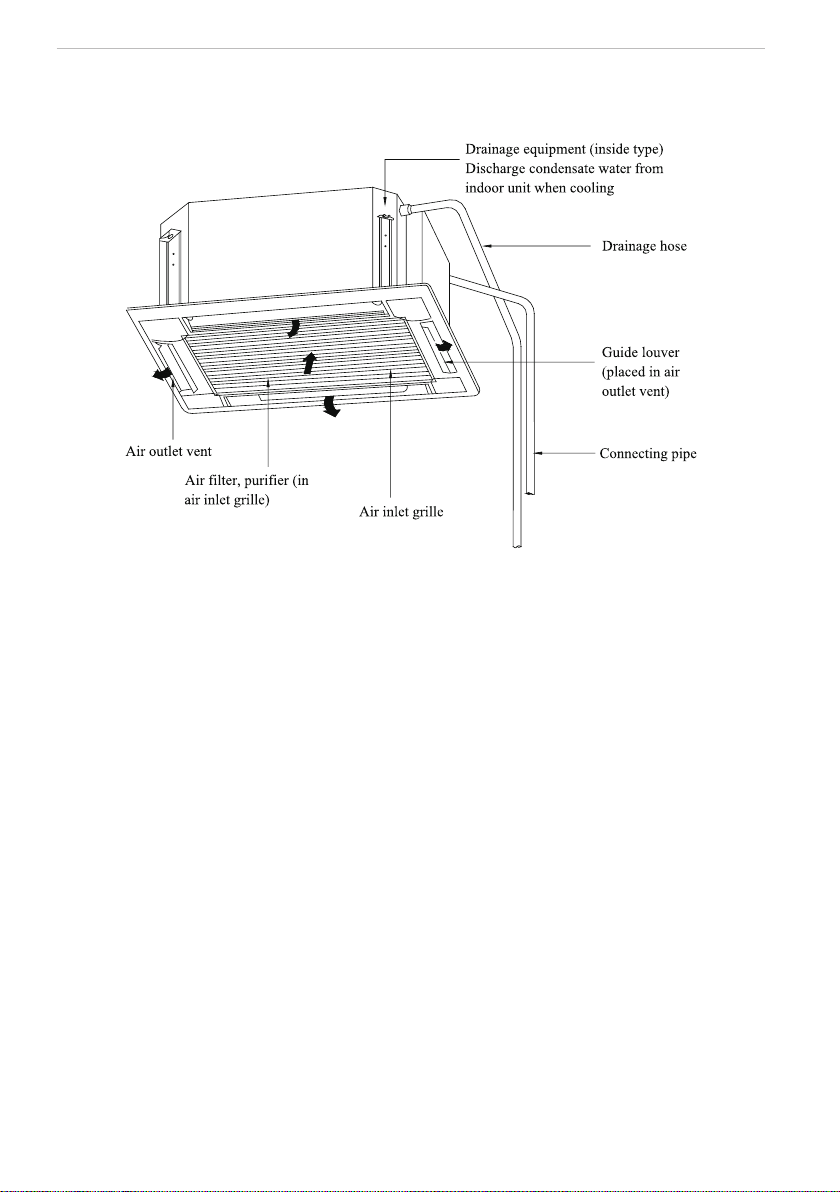
Constitutes and Names of Parts of Compact Panel Cassette Type Indoor Unit
10
3 Constitutes and Names of Parts of Compact Panel Cassette Type
Indoor Unit
Working Temperature Range
11
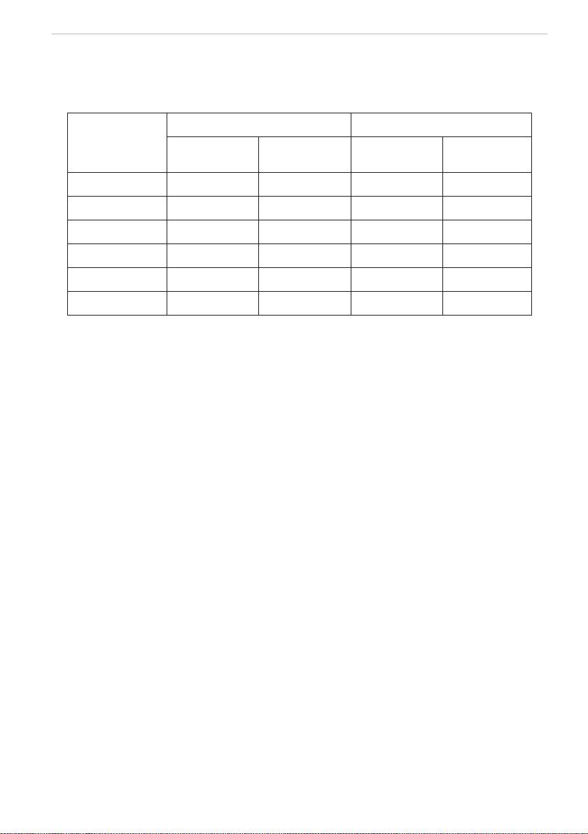
4 Working Temperature Range
Working Temperature Range
Indoor side state Outdoor side stae
Dry bulb
temp.
℃
Wet bulb
temp.
℃
Dry bulb
temp.
℃
Wet bulb
temp.
℃
Rated Cooling 27 19 35 24
Max. cooling 32 23 48 26
Min. cooling 21 15 18
—
Rated Heating 20 15 7 6
Max. heating 27
—
24 18
Min. heating
20 15 -
15
-
16
Malfunction Debarring
12
5 Malfunction Debarring
Warning!
◆
Cut down the main power switch immediately if malfunction (such as smell the burning odor
etc.) happened, and then contact service center. If the abnormal state is maintained, the unit may be
damaged or electric shock or re may be happened.
◆
Do not ret the conditioner. Please contact service center to repair or move the conditioner.
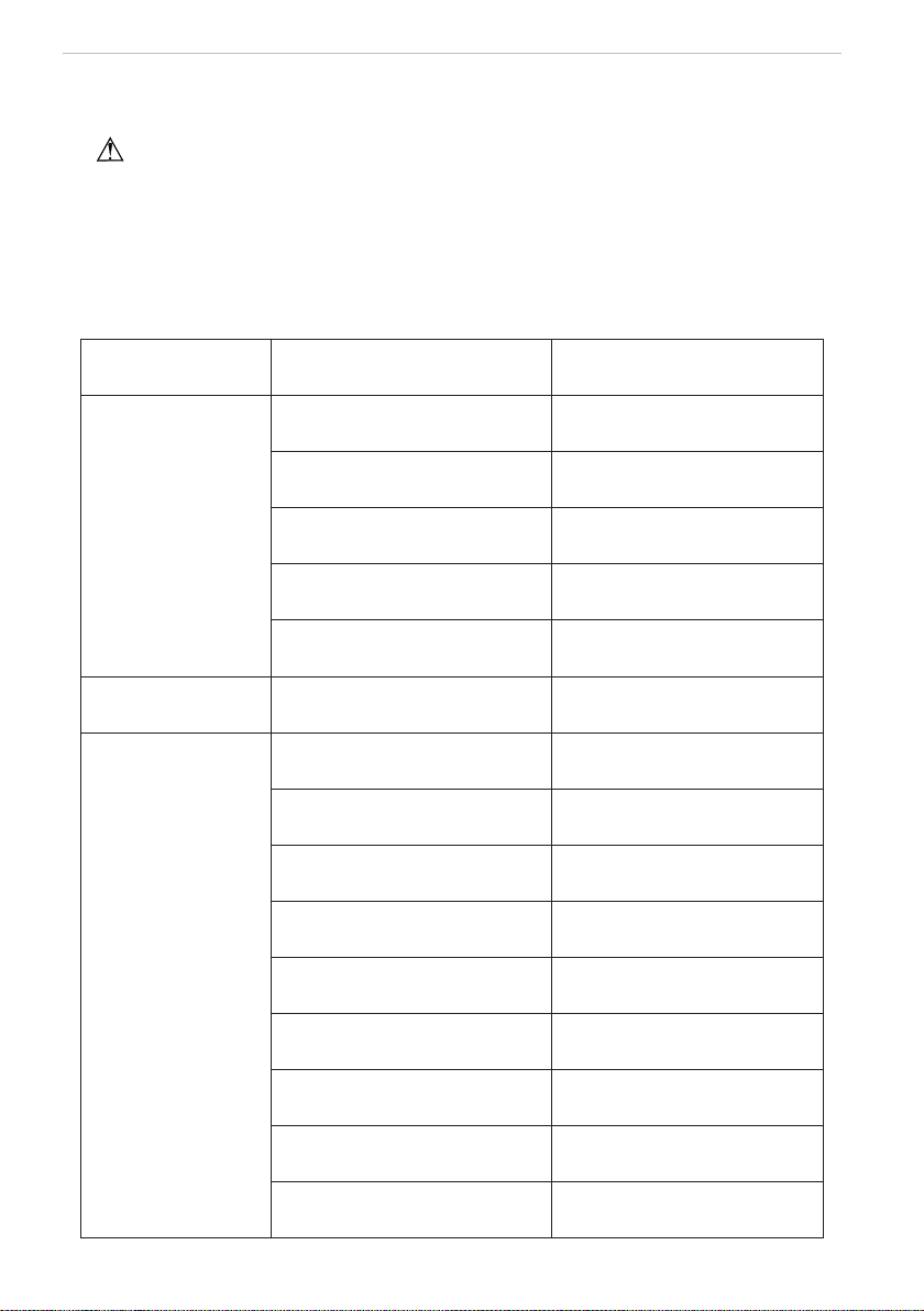
5.1 Check the following items before contacting maintenance center
Phenomena Reason Remedial Measures
Air conditioner doesn’t
run at all
Blow of fuse or breaker Change fuse or close breaker
Power cut
Restart when there is power
supply
Don’t connect with power Connect power well
Low batteries of wireless remote
controller
Change new batteries
Wireless remote controller exceed
remote control area
Signal could be received within
8m
Air conditioner runs
but stops immediately
Blockage in inlet or outlet vent of
indoor or outdoor unit
Clean out blockage
Abnormal cooling or
heating
Blockage in inlet or outlet vent of
indoor or outdoor unit
Clean out blockage
Improper of temp. setting
Adjust settings in wireless remote
controller
Low setting of fan speed
Adjust settings in wireless remote
controller
Incorrect of wind direction
Adjust settings in wireless remote
controller
Door or window opened Close
Direct sun burn
Hang curtain or jalousie before
windows
Too many people in room
Too many heater in room
Filter blocked by dirt Clean lter
Malfunction Debarring
13
5.2 Instruction
If problem still cannot found out after above checking, please contact service center and instruct
phenomena and model.
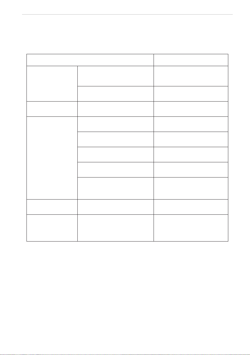
5.3 The following circumstance are not malfunction
“Malfunction” Reason
Air conditioner doesn’t
run
Start up unit immediately after
turned off
The overload protects switch
makes it run after 3 minutes delay.
When opening power
Run for about 1 minute without
other actions
Mist is blown from air
conditioner
When cooling
The high humidity air in room is
cooled rapidly
Noise is heard from
air conditioner
Slight click sound heard once
begin running
Sound of initialization for electric
expand valve
Hissing sound heard continuously
when cooling
The sound for gas refrigerant
owing in the unit
Hissing sound heard when staring
or stopping
The sound for gas refrigerant
stops ow
Slight hissing sound heard when
running or after running
Sound for running of drainage
system
Creak sound heard when running
or after running
The grating sound caused by
expands of panel and other parts
for the change of temperature
Dust be blown for air
conditioner
Started up after long time’s doesn’t
runs
Dust in indoor unit be blown out
Odor gives out from
air conditioner
When running
This is because when air
conditioning, odors or cigarette
smoke from the room that was
sucked in is discharged again.
5.4 After-sales Service
When having quality or other problems when purchasing air conditioner, please contact the local
service center.
Maintenance Method
14
6 Maintenance Method
When air conditioner won’t be used for a long time, please cut off the main power supply
of air conditioner.
Warning!
◆
Do turn off the unit and cut off the main power supply when cleaning the air conditioner,
otherwise electric shock or harm may happen.
◆
It is forbidden to wash air conditioner by water rinsing, otherwise electric shock may happen.
6.1 Cleaning air lter
Air lters should be cleaned by professionals with proper operation to ensure personal safety.
When the usage environment has lots of dust, air lter should be cleaned more frequently (about
once 6 months).
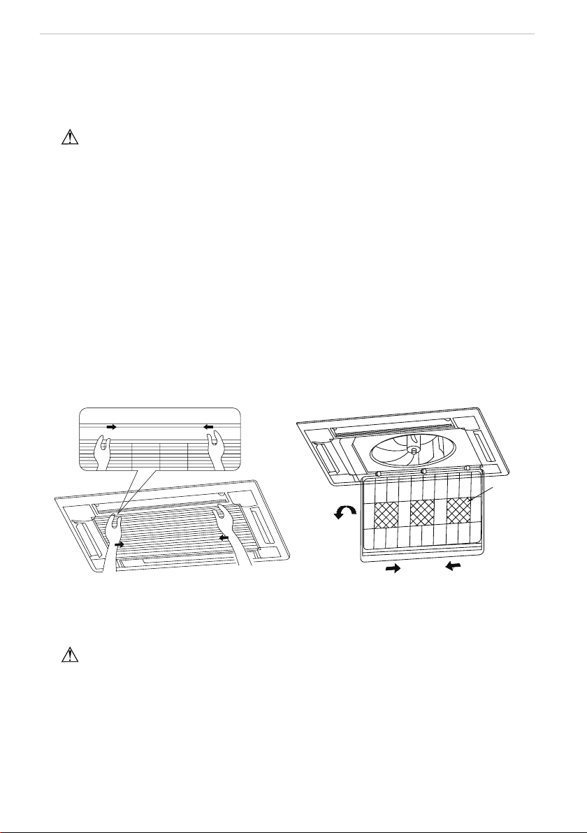
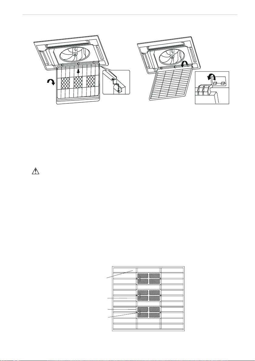
(1). Open air inlet grille
Loosen two screws on the air inlet grille with a screwdriver. And
pull the 2 handle on air inlet
grille at the same time with the direction showed by arrow in g.17, pull down slowly. (Reverse when
closing)
(2). Disassembly air lter
As shown in fig.18, pull the handle behind air inlet grille, raise it and disassembly. Then
discharge the 3 purier xed on lter.
purifier
Fig.17 Fig.18
(3). Clean
Adopts cleaner or water to wash lter; if the lter is too dirty ( like oil stain on it ), adopts warm
water ( lower than 45
℃
) with neutral scourer to clean it, then dry it in the shade.
Note
!
Do not clean the filter by hot water whose temp. is higher than 45
℃
to prevent fade or
deformation.
Do not burn it on re or the lter would catches re or deformation.
(4). Install air lter
Fix the 3 puriers on lter, install lter on the several bulges on top of air inlet grille, pull the
handle behind air inlet grille toward inside to x lter. As shown in g.19.
Maintenance Method
15
(5). Close air inlet grille (Refer to the 1st step)
Maintenance Method
Fig.19 Fig.20
6.2 Clean air inlet grille
(1). Open air inlet grille (the same with the 1st step of Clean Air Filter)
(2). Take out air lter (the same with the 2nd step of Clean Air Filter)
(3). Take out air inlet grille
Open air inlet grille for an angle of 45°, as shown in g.20, rise it.
(4). Clean
Clean it by pubescence brush, water and neutral cleaning, then throw water or dry it.
Note
!
Do not use water above 45
℃
to wash the panel to prevent fade or deformation.
(5). Install air inlet grille (refer to 3rd step)
(6). Install air lter (refer to the 4th step of Clean Air Filter)
(7). Close air inlet grille (refer to the 1st step)
6.3 Install and change of air purier
(1). Open air inlet grille (the same the 1st step of Clean Air Filter)
(2). Disassembly purier
As shown in g.21, disassembly air lter, screw out xing bolts xed on purier on lter, then
purier could be disassembly.
(3). Take out the package sack of static ber net lter, then install the lter in stand of purier,
and x purier on air lter.
(4). Install air lter (the same with the 4th step of Clean Air Filter)
Fix bolt of
purifier
Stand for purifier
Purifier filter
Air filter
Fig.21

Maintenance Method
16
Function and usage period for air purifying
◆
Could adsorb CO, CO
2
, benzene, aldehydes and odor of gasoline etc..
◆
Could adsorb deleterious material that is smaller than 1μm in air, as dust, pollen, bacteria,
and virus.
◆
Usage period is 6 months to 1 year. If it is necessary to be changed, purchase new purier in
the nearest Impecca special engaged maintenance
center. 6.4 Clean Outlet vent and Surface
Panel
◆
Clean the surface panel by soft dry cloth or wet cloth with neutral scourer.
◆
It is forbidden to clean surface panel by gasoline, benzene, diluents, cleansing powder etc..
◆
If the guide louver is too dirty, it may be removed to be cleaned. (As narrated below)
Disassembly and install of guide louver
(1). Disassembly guide louver
Screw bolts in both end of guide louver to loose.
Note
!
Do not wipe guide louver powerfully when cleaning, otherwise uff on surface would fall off.
(2). Install guide louver
Rotate guide louver slightly could install the protruding edge of both end into grooves on both
end of guide louver, and then tighten bolts.
6.5 Maintenance before or after usage season
Check before the usage season
◆
Check if there is blockage in inlet or outlet vent of air conditioner.
◆
Check if the earthing wire had earthed reliably.
◆
Check if the air lter had been installed well.
◆
In order to start up the air conditioner smoothly after long time’s turned off, turn on the main
power supply 8 hours before turning on the air conditioner.
Maintenance after usage season
◆
Clean lter and body of air conditioner.
◆
Cut off the main power supply of air conditioner.
◆
The cooling or heating capacity and sound level are tested before leaving factory.
◆
If the parameter changed, refer to the data offered on nameplate.
6.6 CUSTOMER SUPPORT
Before contacting customer support, please see the troubleshooting guide above.
Visit our website to contact us, find answers to Frequently Asked Questions, and for other resources which
may include an updated version of this user's guide.
WWW.IMPECCA.COM
If you wish to contact us by phone, please be sure to have your model number and serial number ready
and call us between 9:00am and 6:00pm ET, at +1 866-954-4440.
Keep tabs on Impecca's newest innovations & enter contests via our social network feeds:
www.facebook.com/Impecca/
www.instagram.com/impecca/
@impeccausa

© 2016 Impecca, a division of LT Inc., Wilkes Barre, PA.

Thank you for choosing Impecca Air Conditioners. Please read this
owner’s manual carefully before operation and retain it for future reference.
Wired Controller
IS-TT850
User's Manual

User Notice
ƹ
ƹ
ƹ
ƹ
ƹ
ƹ
Please carefully read this manual before installation and use of this product
(QVXUHthere is separate SRZHUVXSSO\IRUHDFKLQGRRUXQLW
Never install wired controller in a
wet place or under direct sunlight.
Shielded twisted pair line must be substituted as signal line for wired controller if the unit is
installed in the place where there is electromagnetic interference.
Make sure communication line is connected into correct port to avoid communication
malfunction.
Never knock, throw or frequently disassemble the wired controller.
Never operate the wired controller with wet hand.

Contents
1 Display Section................................................................................................ 1
1.1 Controller's LCD ........................................................................................1
1.2 Instruction to LCD ....................................................................................... 2
2 Buttons ............................................................................................................ 3
2.1 Layout of Buttons .......................................................................................3
2.2 Functions of Buttons ................................................................................... 3
3 Operation Instructions ..................................................................................... 4
3.1 On/Off ......................................................................................................... 4
3.2 Mode Setting .............................................................................................. 4
3.3 Temperature Setting ................................................................................... 4
3.4 Fan Setting ................................................................................................. 5
3.5 Timer Setting .............................................................................................. 5
3.6 Swing Setting ............................................................................................. 7
3.7 Sleep Setting .............................................................................................. 8
3.8 Turbo Setting .............................................................................................. 9
3.9 E-heater Setting .......................................................................................10
3.10 Blow Setting ........................................................................................... 11
3.11 Other Functions ...................................................................................... 12
4 Installation and Dismantlement ..................................................................... 12
4.1 Connection of the Signal Line of the Wired Controller ............................. 12
4.2 Installation of the Wired Controller ........................................................... 12
4.3 Dismantlement of the Wired Controller .................................................... 14
5 Errors Display ................................................................................................ 14
1
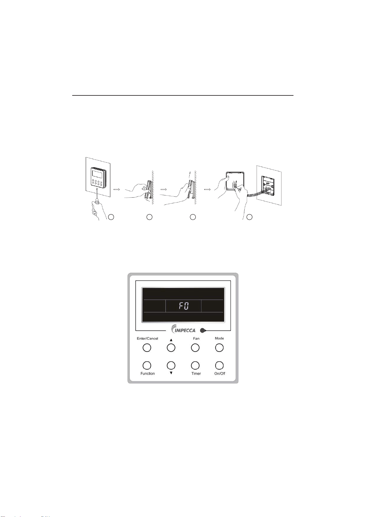
1 Display Section
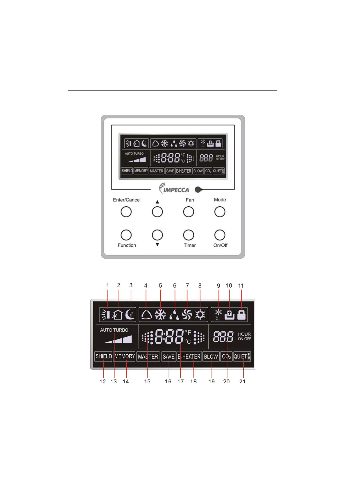
Fig1.1.1 Diagram of wired controller
1.1 LCD Display of Wired Controller
Fig.1.1.2 LCD display
Wired Controller IS-TT850
2
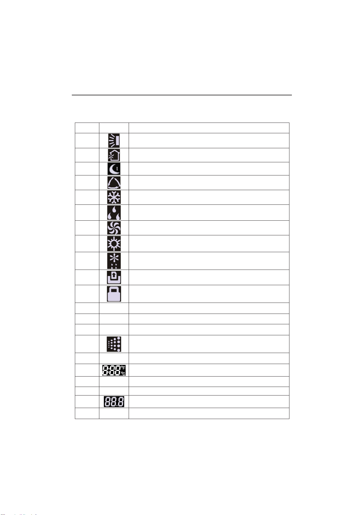
1.2 Instruction to LCD Display
Table 1.1
No. Symbols Description
1
Swing function
2
Air exchange function (this function is yet unavailable for this unit).
3
Sleep function (Only sleep 1).
4
Each kind of running mode of indoor unit (auto mode)
5
Cooling mode
6
Dry mode
7
Fan mode
8
Heating mode
9
Defrosting function for the outdoor unit.
10
Gate-control function (this function is yet unavailable for this unit).
11
Lock function.
12 SHIELD
Shield functions (Button operation, temperature setting, On/Off operation,
Mode setting are disabled by the remote monitoring system.)
13 Turbo Turbo function state
14 MEMORY
Memory function (The indoor unit resumes the original setting state after
power failure and then power recovery).
15
It blinks under on state of the unit without operation of any button.
16
SAVE
Energy-saving function (this function is yet unavailable for this unit).
17
Ambient/setting temperature value
18 E-HEATER Electric auxiliary heating function.
19 BLOW Blow function.
20
Timing value.
21 QUIET
Quiet function (two types: quiet and auto quiet)
(this function is yet unavailable for this unit).
Wired Controller IS-TT850

3
2 Buttons
2.1 Layout of Buttons
2.2 Functions of Buttons
Table 2.1
No. Name Function
1 Enter/Cancel Function selection and cancellation.
2 Ÿ
ķ
Running temperature setting of the indoor unit, range:
61°F-86°
F(16°C-30°C).
ĸ
Timer setting, range:0.5(30 minutes) - 24 (hours).
6 ź
3 Fan
Setting of the low/middle/high/auto fan speed.
4 Mode Setting of the Cooling/Heating/Fan/Dry/Auto mode of the indoor unit.
5 Function Switchover among the functions of Turbo/Save/E-heater/Blow etc..
7 Timer Timer setting.
8 On/Off
Turn on/off the indoor unit.
4+2 Mode + Ÿ
With the A/C powered off, press these two buttons together for 5
seconds to toggle the Memory function. With Memory on, the unit will
return the the previous setting after resuming from a power failure.
With Memory toggled off, it will stay off
3+6 )DQź
With the A/C powered off, press these two buttons together for 5 seconds
to determine if your unit is capable of just cooling or both cooling and
heating, indicated by the symbols shown.
2+6 Ÿź
Press these two buttons together for 5 seconds to toggle the lock function.
Wired Controller IS-TT850
4+6
Mode ź
With the A/C powered off, press these two buttons together for 5 seconds to
toggle between Fahrenheit and Celsius.
4
3 Operation Instructions
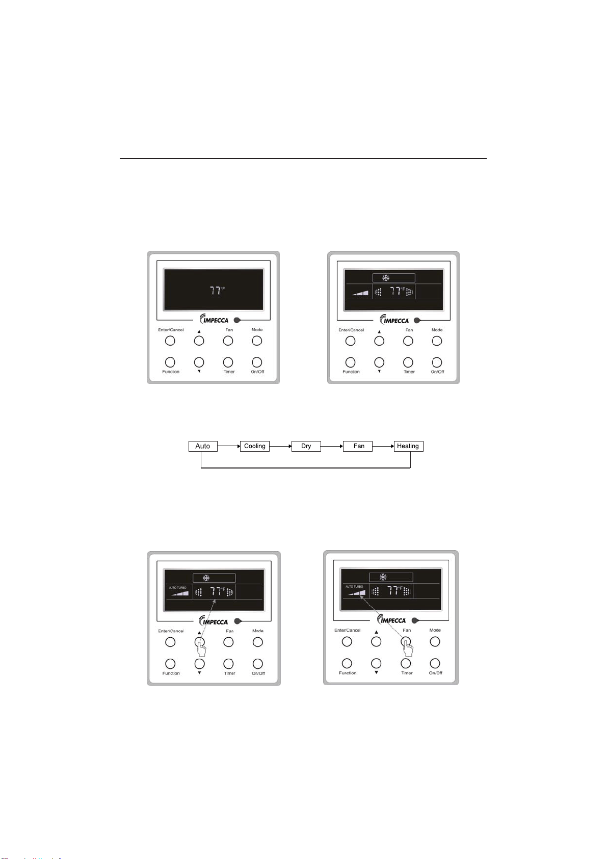
3.1 On/Off
Press On/Off button to toggle your A/C's power.
Note: The state shown in Fig.3.1.1 indicates the “Off” state of the unit after power has been restored
to the unit. The
screen shown in Fig.3.1.2 indicates the “On” state of the unit after power on.
Fig.3.1.1 “Off” State Fig.3.1.2 “On” State
3.2 Mode Setting
Under ON state of the unit, press the Mode to switch the operation modes as the
following sequence: Auto–Cooling–Dry–Fan–Heating.
3.3 Temperature Setting
3UHVVŸRUźWRLQFUHDVHGHFUHDVHWKHSUHVHWWHPSHUDWXUH,ISUHVVLQJHLWKHURIWKHP
continuously, the temperature will be increased or decreased by 1° every half a second,as
shown in Fig.3.3.1.
In the Cooling, Dry, Fan or Heating mode, the temperature setting range is 61°F-86°
F(16°C-30°C). In the Auto mode, the setting temperature not manually adjustable.
Fig.3.3.1 Fig.3.4.1
Wired Controller IS-TT850
5
3.4 Fan Setting
While the unit is powered on, press
Fan
and then fan speed of the indoor unit will change
circularly as shown in Fig.3.4.1.
Low Middle
High
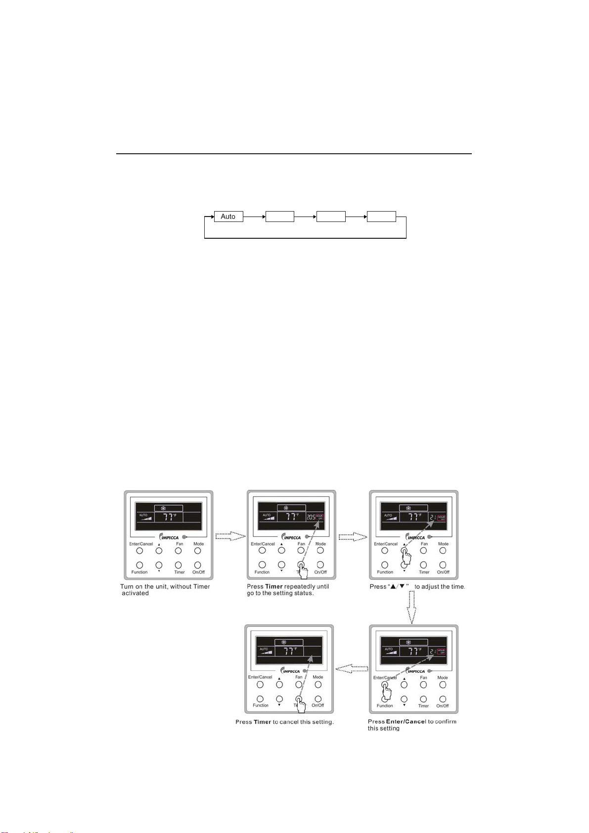
3.5 Timer Settings
While the unit is powered on, pressing the Timer button allows you to
set the delay until the
unit turns off. While the unit is powered off, pressing the Timer button allows you to set the dealy
until the unit turns on.
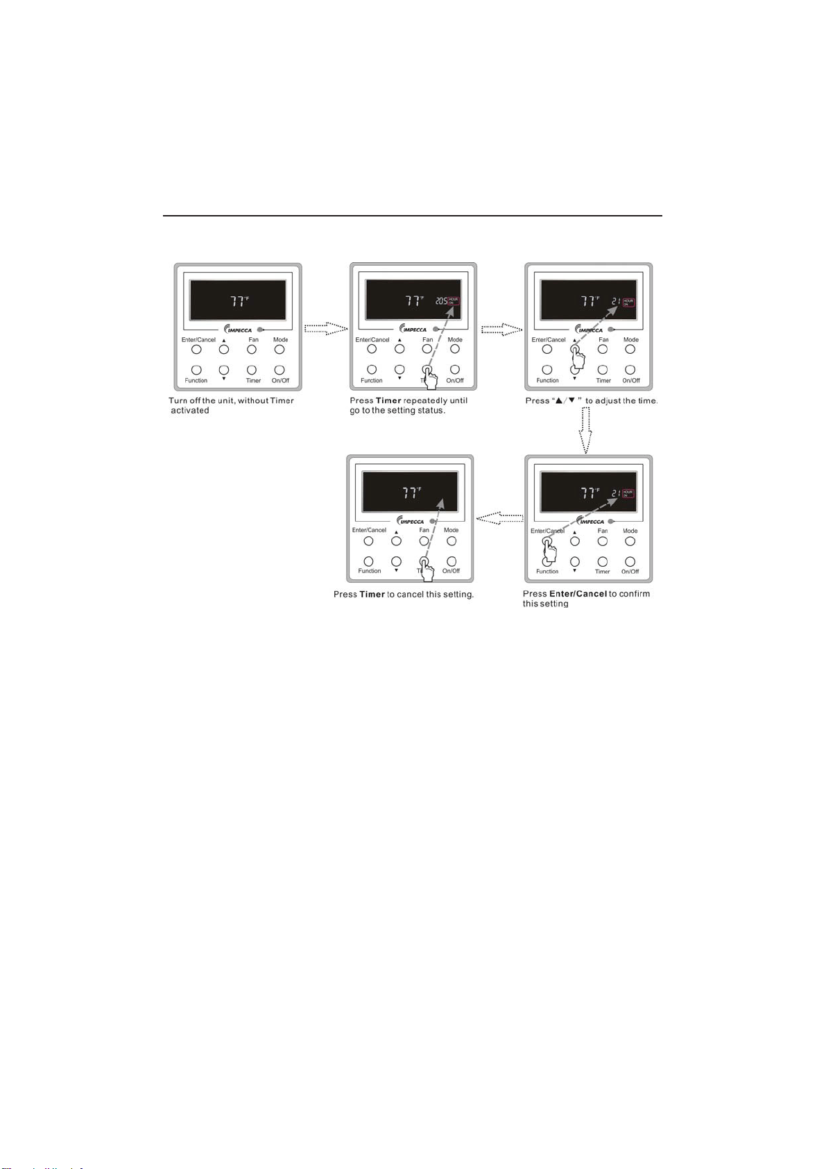
• 7LPHURQVHWWLQJ details
With the unit turned off, and no timer already programmed, press the Timer button. The
display will show "0.5" with "Hour on" blinking. PressŸorźbutton to adjust delay until unit
turns on and press Timer or Enter/Cancel to confirm.
• Timer off setting details:
With the unit turned on, and no timer already programmed, press the Timer button. The display
will show "0.5" with "Hour off" blinking.
• Timer off setting details:
With the unit turned on, and no timer already programmed, press the Timer button. The display will
show "0.5" with "Hour off" blinkingSUHVVŸRUźEXWWRQWRDGMXVWdelay until unit turns on and press
Timer or Enter/Cancel to confirm.
&DQFHOWLPHU
After setting of timer, if Timer button is pressed, LCD won’t display xx. Hour so that timer setting is
canceled.
Timer off setting under the “On” state of the unit is shown as Fig.3.5.1.
Fig.3.5.1 Timer off Setting under the “On” State of the Unit
Wired Controller IS-TT850
(Fig. 3.4.1)
6
Timer on setting under the “Off” state of the unit is shown as Fig.3.5.2.
Fig.3.5.2 Timer on Setting under the “Off” State of the Unit
7LPHUUDQJHKU(YHU\SUHVVRIŸRUźZLOOPDNHWKHVHWWLPHLQFUHDVHGRUGHFUHDVHGE\
0.5hr. If either of them is pressed continuously, the set time will increase/ decrease by 0.5hr every
0.5s.
Wired Controller IS-TT850
7
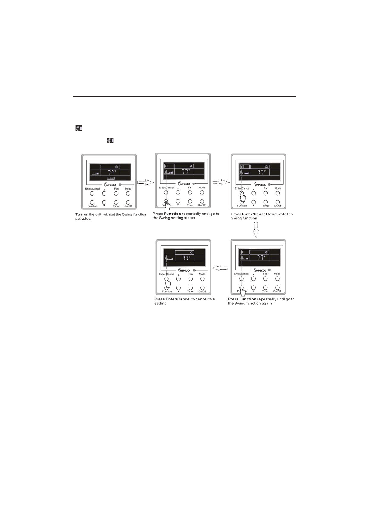
3.6 Swing Setting
Swing On: Press Function under on state of the unit to activate the swing function. In this case,
ZLOOEOLQN$IWHUWKDWSUHVV(QWHU&DQFHOWRPDNHDFRQ¿UPDWLRQ
Swing Off: When the Swing function is on, press Function to enter the Swing setting
interface,with
blinking. After that, press Enter/Cancel to cancel this function. Swing setting is
shown as Fig.3.6.1.
Fig.3.6.1 Swing Setting
Notes:
ķ
Sleep, Turbo or Blow setting is the same as the Swing setting.
ĸ
After the setting has been done, it has to press the key “Enter/Cancel” to back to the setting
VWDWXVRUTXLWDXWRPDWLFDOO\¿YHVHFRQGVODWHU
Wired Controller IS-TT850
8
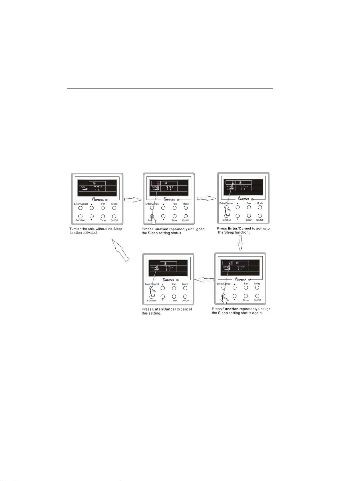
3.7 Sleep Setting
Sleep on: Press Function under the On state of the unit till the unit enters the Sleep setting
VWDWH$IWHUWKDWSUHVV(QWHU&DQFHOWRFRQ¿UPWKLVVHWWLQJ
Sleep off: When the Sleep function is activated, press Function to enter the Sleep setting
status. After that, press Enter/Cancel to cancel this function.
In the Cooling or Dry mode, the temperature will increase by 1°C after the unit runs under
Sleep1 for 1hr and 1°C after another 1hr.After that, the unit will run at this temperature.
In the Heating mode, the temperature will decrease by 1°C after the unit runs under Sleep 1 for
1hr and 1°C after another 1hr. After that, the unit will run at this temperature.
Sleep setting is shown as Fig.3.7.1.
Fig.3.7.1. Sleep Setting
Wired Controller IS-TT850
9
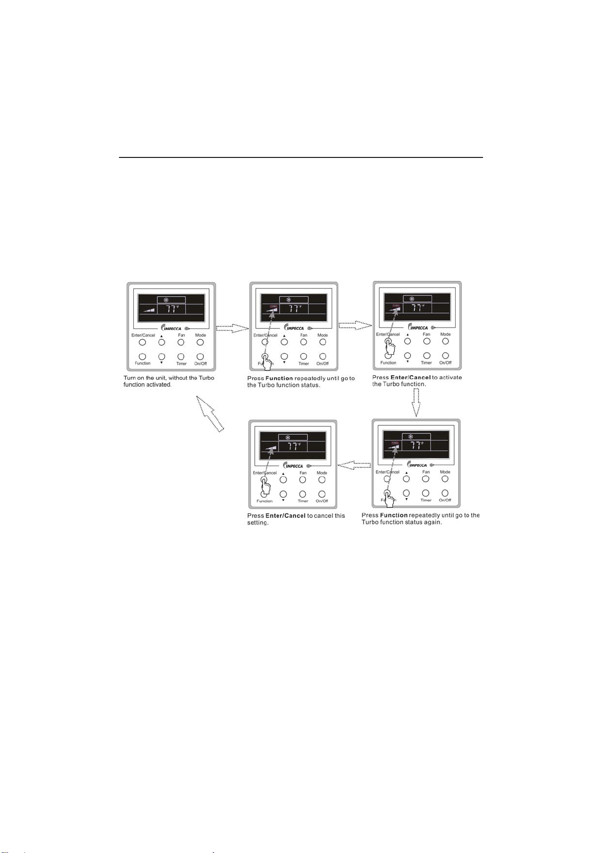
3.8 Turbo Setting
Turbo function: The unit at the high fan speed can realize quick cooling or heating so that the
room temperature can quickly approach the setting value.
In the Cooling or Heating mode, press Function till the unit enters the Turbo setting status and
WKHQSUHVV(QWHU&DQFHOWRFRQ¿UPWKHVHWWLQJ
When the Turbo function is activated, press Function to enter the Turbo setting status and then
press Enter/Cancel to cancel this function.
Turbo function setting is as shown in Fig.3.8.1.
Fig.3.8.1 Turbo Setting
Wired Controller IS-TT850
10
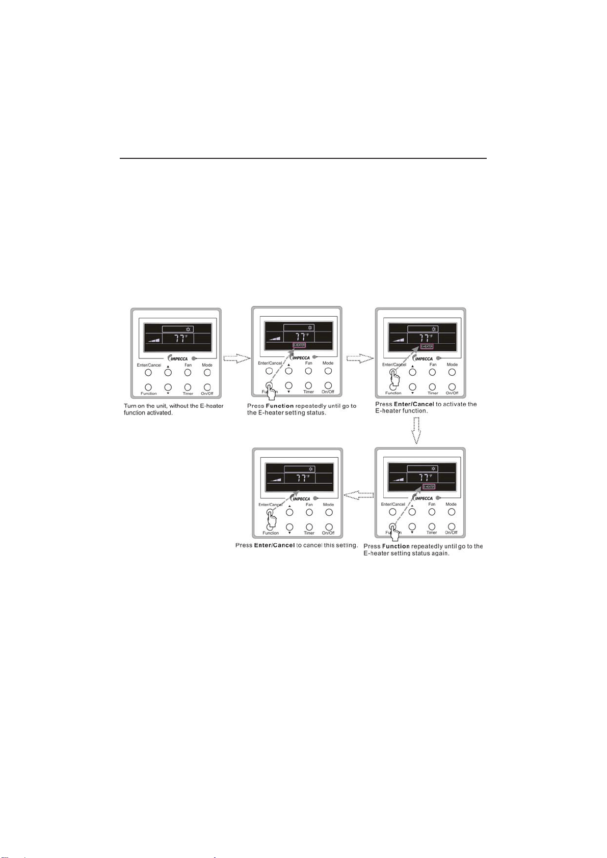
3.9 E-heater Setting
E-heater (auxiliary electric heating function): In the Heating mode, E-heater is allowed to be
WXUQHGRQIRULPSURYHPHQWRIHI¿FLHQF\
Once the wired controller or the remote controller enters the Heating mode, this function will be
turned on automatically.
Press Function in the Heating mode to enter the E-heater setting interface and then press
Enter/Cancel to cancel this function.
Press Function to enter the E-heater setting status, if the E-heater function is not activated,
and then press Enter/Cancel to activate it.
The setting of this function is shown as Fig.3.9.1 below:
Fig.3.9.1 E-heater Setting
Wired Controller IS-TT850
11
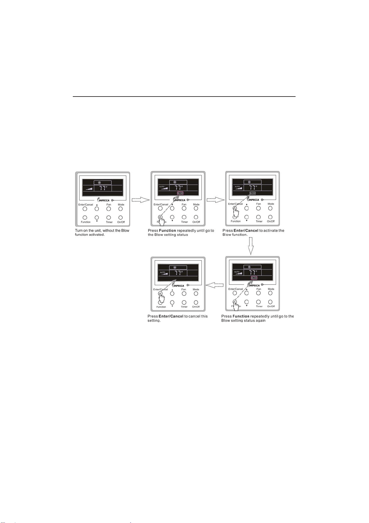
3.10 Blow Setting
Blow function: After the unit is turned off, the water in evaporator of indoor unit will be
automatically evaporated to avoid mildew.
In the Cooling or Dry mode, press Function till the unit enters the Blow setting status and then
press Enter/Cancel to active this function.
When the Blow function is activated, press Function to the Blow setting status and then press
Enter/Cancel to cancel this function.
Blow function setting is as shown in Fig.3.10.1
Fig.3.10.1 Blow Setting
Notes:
ķ
When the Blow function is activated, if turning off the unit by pressing On/Off or by the
remote controller, the indoor fan will run at the low fan speed for 2 min, with “BLOW” displayed on
the LCD. While, if the Blow function is deactivated, the indoor fan will be turned off directly.
ĸ
Blow function is unavailable in the Fan or Heating mode.
Wired Controller IS-TT850
12
3.11 Other Functions
a. Lock
8SRQVWDUWXSRIWKHXQLWZLWKRXWPDOIXQFWLRQRUXQGHUWKH³2II´VWDWHRIWKHXQLWSUHVVŸDQGźat
the same time for 5s till the wired controller enters the Lock function. In this case, LCD displays
.
After that, repress these two buttons at the same time for 5s to quit this function.
Under the Lock state, any other button press won’t get any response.
b. Memory
0HPRU\VZLWFKRYHU8QGHUWKH³2II´VWDWHRIWKHXQLWSUHVV0RGHDQGŸDWWKHVDPHWLPHIRU
5s to switch memory states between memory on and memory off. When this function is activated,
Memory will be displayed. If this function is not set, the unit will be under the “Off” state after power
failure and then power recovery.
Memory recovery: If this function has been set for the wired controller, the wired controller after
power failure will resume its original running state upon power recovery. Memory contents: On/
Off,Mode, set temperature, set fan speed and Lock function.
4 Installation and Dismantlement
4.1 Connection of the Signal Line of the Wired Controller
Ɣ2SHQWKHFRYHURIWKHHOHFWULFFRQWUROER[RIWKHLQGRRUXQLW
Ɣ/HWWKHVLQJOHOLQHRIWKHZLUHGFRQWUROOHUWKURXJKWKHUXEEHUULQJ
Ɣ&RQQHFWWKHVLJQDOOLQHRIWKHZLUHGFRQWUROWRWKHSLQVRFNHWRIWKHLQGRRUXQLW3&%
Ɣ7LJKWHQWKHVLJQDOZLUHZLWKWLHV
Ɣ7KHFRPPXQLFDWLRQGLVWDQFHEHWZHHQWKHPDLQERDUGDQGWKHZLUHGFRQWUROOHUFDQEHXSWR
20 meters ( the standard distance is 8 meters)
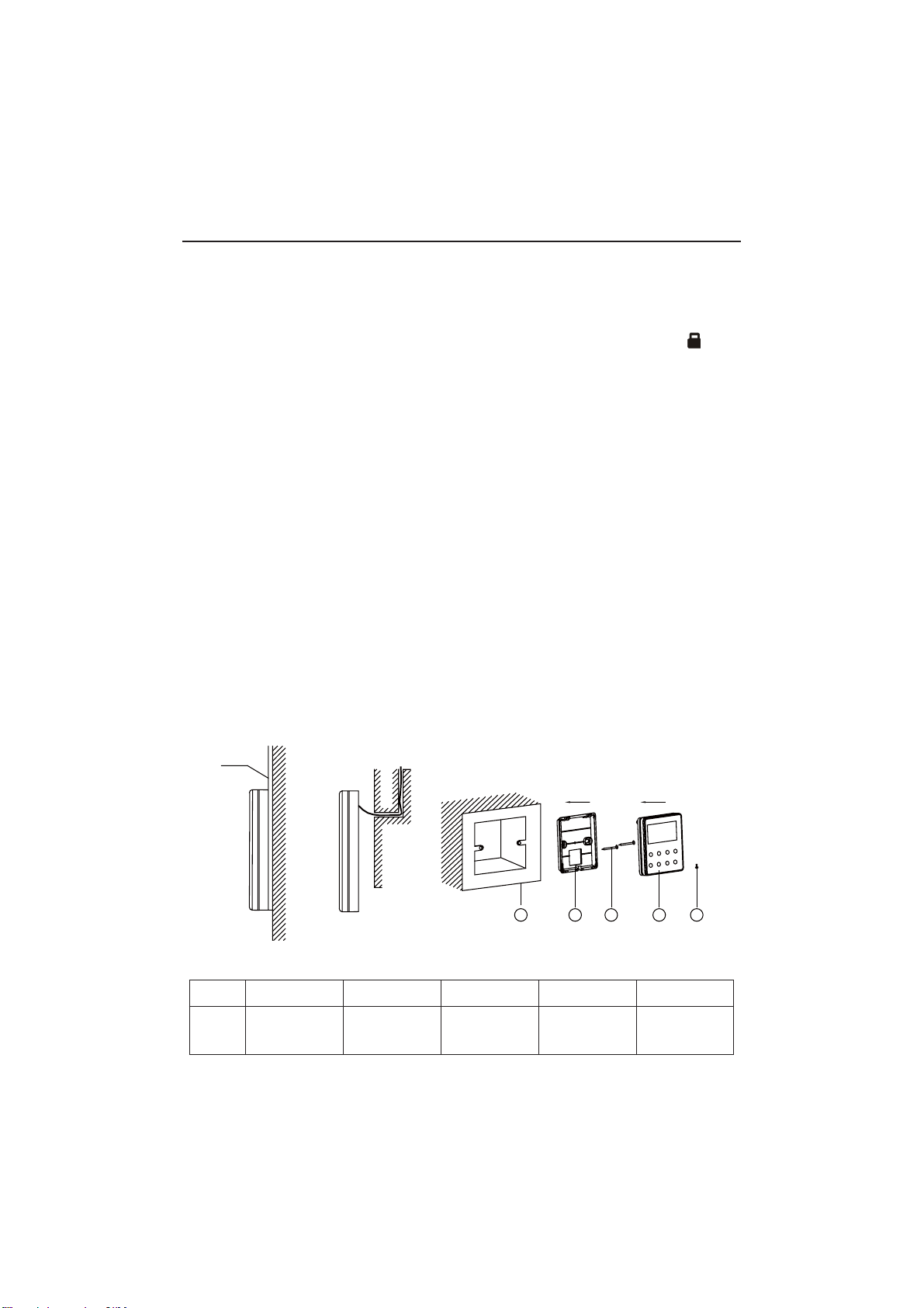
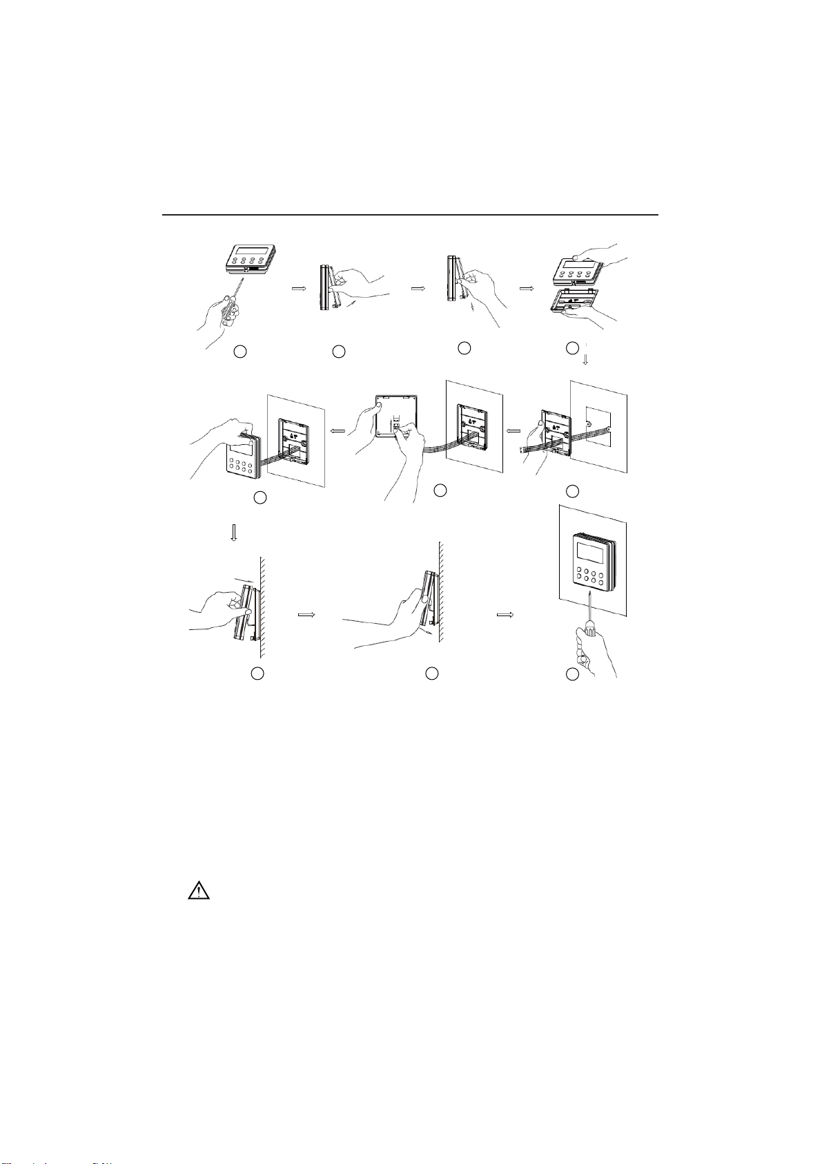
4.2 Installation of the Wired Controller
1
PVC Pipe
3 4 52
Fig.4.1 Accessories for the Installation of the Wired Controller
Table 4.1
No.12345
Name
Socket box
embedded
in the wall
*
Back-plate of
the Wired
Controller
Screw
M4X25
*
Front Panel
of the Wired
Controller
Screw
ST 2.9X6*
Wired Controller IS-TT850
*Not included
13
1
6
8 9
10
7
3 4
5
2
Fig.4.2
Fig.4.2 shows the installation steps of the wired controller, but there are some issues that need
your attention.
1) Prior to the installation, please firstly cut off the power supply of the wire buried in the
installation hole, that is, no operation is allowed with electricity during the whole installation.
2) Pull out the four-core twisted pair line from the installation holes and then let it go through
the rectangular hole behind the back-plate of the wired controller.
6WLFNWKHVROHSODWHRIWKHZLUHGFRQWUROOHUWRWKHZDOORYHUWKHLQVWDOODWLRQKROHDQGWKHQ¿[LW
with screws M4X25.
4) Insert the four-core twisted pair line into the slot of the wired controller and then buckle the
front panel and the back-plate of the wired controller together.
)LQDOO\¿[WKHIURQWSDQHODQGWKHVROHSODWHRIWKHZLUHGFRQWUROOHUWLJKWO\E\VFUHZV67;
CAUTION!
Please pay special attention to the followings during the connection to avoid the malfunction of
the air conditioning unit due to electromagnetic interference.
ķ
Separate the signal and communication lines of the wired controller from the power cord
Wired Controller IS-TT850
14
and connection lines between the indoor and outdoor unit, with a minimum interval of 20cm,
otherwise the communication of the unit will probably work abnormally.
ĸ
If the air conditioning unit is installed where is vulnerable to electromagnetic
interference,then the signal and communication lines of the wired controller must be the shielding
twisted pair lines.
4.3 Dismantlement of the Wired Controller
1 3 42
5 Errors Display
If there is an error occurring during the operation of the system, the error code will be displayed
on the LCD, as show in Fig.5.1. If multi errors occur at the same time, their codes will be displayed
circularly.
Note: In event of any error, please turn off the unit and contact the professionally skilled
personnel.
Fig.5.1
Wired Controller IS-TT850
Wired Controller IS-TT850
15
Table 5.1 Meaning of Each Error
Error
Error
Code
Error
Error
Code
Return air temperature sensor open/
short circuited
F1 Drive board communication error P6
evaporator temperature sensor open/
short circuited
F2 Compressor overheating protection H3
Indoor unit liquid valve temperature
sensor open/short circuited
b5 Indoor and outdoor units unmatched LP
Indoor gas valve temperature sensor
open/ short circuited
b7
Communication line misconnected or
expansion valve error
dn
IPM temperature sensor open/short
circuited
P7 5XQQLQJPRGHFRQÀLFW E7
Outdoor ambient temperature sensor
open/ short circuited
F3 Pump-down Fo
Outdoor unit condenser mid-tube
temperature sensor open/short circuited
F4 Jumper error C5
Discharge temperature sensor open/
short circuited
F5 Forced defrosting H1
Indoor and outdoor communication error E6 Compressor startup failure Lc
DC bus under-voltage protection PL High discharge temperature protection E4
DC bus over-voltage protection PH Overload protection E8
Compressor phase current sensing
circuit error
U1 Whole unit over-current protection E5
Compressor demagnetization protection HE Over phase current protection P5
PFC protection Hc Compressor desynchronizing H7
IPM Temperature Protection P8 IPM Current protection H5
Over-power protection L9
Compressor phase loss/reversal
protection
Ld
System charge shortage or blockage
protection
F0
Frequency restricted/reduced with whole
unit current protection
F8
Capacitor charging error PU
Frequency restricted/reduced with IPM
current protection
En
High pressure protection E1
Frequency restricted/reduced with high
discharge temperature
F9
Low pressure protection E3
Frequency restricted/reduced with anti-
freezing protection
FH
Compressor stalling LE
Frequency restricted/reduced with
overload protection
F6
Over-speeding LF
Frequency restricted/reduced with IPM
temperature protection
EU
Drive board temperature sensor error PF Indoor unit full water error E9
AC contactor protection P9 Anti-freezing protection E2
Temperature drift protection PE AC input voltage abnormal PP
Sensor connection protection Pd Whole unit current sensing circuit error U5
DC bus voltage drop error U3 4-way valve reversing error U7
Outdoor fan 1 error protection L3 Motor stalling H6
Outdoor fan 2 error protection LA PG motor zero-crossing protection U8

Technical Support
Before calling technical support, please see the troubleshooting guide above. You may also visit
our website at www.impecca.com for answers to Frequently Asked Questions and to contact us.
Email: [email protected]
Phone: +1 866–954–4440
Web: www.impecca.com