
Owner's Manual
ELECTRIC START
42" MOWER
6 SPEED TRANSAXLE
LAWN TRACTOR
Model No.
917.271530
• Safety
• Assembly
• Operation
* Maintenance
* Repair Parts
This product has a low emission engine which operates
differently from previously bulk engines. Before you start the
engine, read and understand this Owner's Manual,
CAUTION:
Read and follow all Safety
Rules and Instructions before
operating this equipment.
For answers to your questions
about this product, Call:
1-800-659-5917
Sears Craftsman Help Line
5 am - 5 pm, Mon - Sat
Sears, Roebuck and Co., Hoffman Estates, II 60179
VisitourCraftsmanwebsite:www.sears.com/craftsman
Warranty ......................................... L.... 2
Safety Rules ......................................... 3
Product Specifications .......................... 6
Assembly .............................................. 8
Operation ............................................ 11
Maintenance Schedule ...................... 17
Maintenance ....................................... 17
Service and Adjustments .................... 21
Storage ............................................... 27
Troubleshooting ................................. 28
Repair Parts ........................................ 32
Parts Ordering ..................... Back Cover
LIMITED'I3NO YEAR WARRANTY ON CRAFTSMAN RIDING EQUIPMENT PARTS
For two (2) years from the date of purchase, if this Craftsman Riding Equipment is
maintained, lubricated and tuned up according to the instructions in the owner's
manual, Sears will repair or replace, free of charge, any parts found to be defective in
material or workmanship. Warranty service is available free of charge by taking your
Craftsman riding equipment to your nearest Sears Service Center. In*home warranty
service is available but a trip charge will apply. This warranty applies only while this
product is in the United States.
This Warranty does not cover:
• Expendable items which become worn during normal use, such as blades, spark
plugs, air cleaners, belts and oil filters.
• Tire replacement or repair caused by punctures from outside objects, such as nails,
thorns, stumps, or glass.
• Repairs necessary because of operator abuse, including but not limited to, damage
caused by towing objects beyond the capability of the riding equipment, impacting
objects that bend the frame or crankshaft, or over speeding the engine.
• Repairs necessary because of operator negligence, including but not limited to,
electrical and mechanical damage caused by improper storage, failure to use the
proper grade and amount of engine oil, failure to keep the deck clear of flammable
debris, or the failure to maintain the equipment according to the instructions con-
tained in the owner's manual.
• Engine (fuel system) cleaning or repairs caused by fuel determined to be contami-
nated or oxidized (stale). In general, fuel should be used within thirty (30) days of its
purchase date.
• Riding equipment used for commercial or rental purposes.
LIMITED 90 DAY WARRANTY ON BATTERY
For ninety (90) days from date of purchase, if any battery included with this riding
equipment proves defective in material or workmanship and our testing determines the
battery will not hold a charge, Sears will replace the battery at no charge. Warranty
service is available free of charge by taking your Craftsman riding equipment to your
nearest Sears Service Center. In-home warranty service is available but a trip charge
will apply. This warranty applies only while this product is in the United States.
TO LOCATE THE NEAREST SEARS SERVICE CENTER OR TO SCHEDULE IN-HOME
WARRANTY SERVICE, SIMPLY CONTACT SEARS AT 1-800-4-MY-HOME
This Warranty gives you specific legal rights, and you may also have other rights which
may vary from state to state.
Seam, Roebuck and Co., D/817 WA, Hoffman Estates, IL 60179
IMPORTANT: This cutting machine is capable of amputating hands and feet and
thrawing objects. Failure to observe the following safety instructions could result in
serious injury or death.
I. GENERAL OPERATION
• Read, understand, and follow all
instructions in the manual and on the
machine before starting.
• Only allow responsible adults, who are
familiar with the instructions, to operate
the machine.
• Clear the area of objects such as
rocks, toys, wire, etc,, which could be
picked up and thrown by the blade.
• Be sure the area is clear of other
people before mowing. Stop machine
if anyone enters the area.
• Never carry passengers.
• Do not mow in reverse unless abso-
lutely necessary. Always look down
and behind before and while backing.
", Be aware of the mower discharge
direction and do not point it at anyone.
Do not operate the mower without
either the entire grass catcher or the
guard in place.
• Slow down before turning.
• Never leave a running machine
unattended. Always rum off blades, set
parking brake, stop engine, and
remove keys before dismounting.
• Turn off blades when not mowing.
• Stop engine before removing grass
catcher or unclogging chute.
• Mow only in daylight or good artificial
light.
• Do not operate the machine while
under the influence of alcohol or drugs.
• Watch for traffic when operating near or
crossing roadways.
• Use extra care when loading or
unloading the machine into a trailer or
truck.
• Data indicates that operators, age 60
years and above, are involved in a
large pementage of riding mower-
related injuries. These operators
should evaluate their ability to operate
the riding mower safely enough to
protect themselves and others from
seriousinjury.
II. SLOPE OPERATION
Slopes are a major factor related to loss-of-
control and tipover accidents, which can
result in severe injury or death, All slopes
require extra caution. If you cannot back up
the slope or if you feel uneasy on it, do not
mow it,
DO:
• Mow up and down slopes, not across.
• Remove obstacles such as rocks, tree
limbs, etc.
• Watch for holes, ruts, or bumps.
Uneven terrain could overturn the
machine. Tall grass can hide ob-
stacles.
• Use slow speed. Choose a low gear
so that you will not have to stop or shift
while on the slope.
• Follow the manufacturer's recommen-
dations for wheel weights or counter-
weights to improve stability.
• Use extra care with grass catchers or
other attachments. These can change
the stability of the machine.
• Keep all movement on the slopes slow
and gradual. Do not make sudden
changes in speed or direction.
• Avoid starting or stopping on a slope, tf
tires lose traction, disengage the
blades and proceed slowly straight
down the slope.
DO NOT:
• Do not turn on slopes unless neces-
sary, and then, turn slowly and gradu-
ally downhill, if possible.
• Do not mow near drop*offs, ditches, or
embankments. The mower could
suddenly turn over if a wheel is over
the edge of a cliff or ditch, or if an edge
caves In.
• Do not mow on wet grass. Reduced
traction could cause stiding.
• Do not try to stabilize the machine by
putting your foot on the ground.
• Do not use grass catcher on steep
slopes.
3
Ill. CHILDREN
Tragic accidents can occur if the operator
is not alert to the presence of children.
Children are often attracted to the
machine and the mowing activity. Never
assume that children will remain where
you last saw them,
• Keep children out of the mowing area
and under the watchful care of another
responsible adult.
• Be alert and turn machine off if children
enter the area.
• Before and when backing, look behind
and down for small children.
• Never carry children. They may fall off
and be seriously injured or interfere
with safe machine operation.
• Never allow children to operate the
machine.
• Use extra care when approaching blind
corners, shrubs, trees, or other objects
that may obscure vision.
IV.SERVICE
• Use extra care in handling gasoline
and other fuels. They are flammable
and vapors are explosive.
-Use only an approved container.
- Never remove gas cap or add fuel
with the engine running. Allow
engine to cool before refueling. Do
not smoke,
-Never refuel the machine indoors.
-Never store the machine or fuel
container inside where there is an
open flame, such as a water heater.
• Never run a machine inside a closed
area.
• Keep nuts and bolts, especially blade
attachment bolts, tight and keep
equipment in good condition.
• Never tamper with safety devices.
Check their proper operation regularly.
• Keep machine free of grass, leaves, or
other debris build-up. Clean oil or fue F
spillage. Allow machine to cool befor_
stodng,
• Stop and inspect the equipment if yol
strike an object. Repair, if necessary,
before restarting.
• Never make adjustments or repairs
with the engine running.
• Grass catcher components are subje
to wear, damage, and detedoration,
which could expose moving parts or
allow objects to be thrown. Frequen
check components and replace with
manufacturer's recommended parts,
when necessary.
• Mower blades are sharp and can cu
Wrap the blade(s) or wear gloves, a
use extra caution when servicing th*
• Check brake operation frequently.
Adjust and service as required.
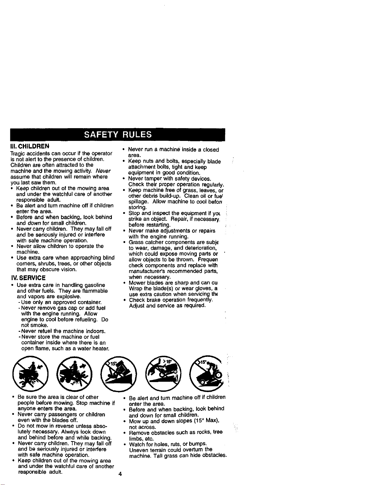
• Be sure the area is clear of other
people before mowing, Stop machine if
anyone enters the area.
• Never carry passengers or children
even with the blades oft,
• Do not mow in reverse unless abso-
lutely necessary. Always look down
and behind before and while backing.
• Never carry children. They may fall off
and be seriously injured or interfere
with safe machine operation,
• Keep children out of the mowing area
and under the watchful care of another
responsible adult,
• Be alert and turn machine off if children
enter the area.
• Before and when backing, look behind
and down for small children.
• Mow up and down slopes (15° Max),
not across.
• Remove obstacles such as rocks, tree
limbs, etc.
• Watch for holes, ruts, or bumps.
Uneven terrain could overturn the
machine. Tall grass can hide obstacles.
4

• Use slow speed. Choose a low gear so
that you will not have to stop or shift
while on the slope.
• Avoid starting or stopping on a slope. If
tires lose traction, disengage the
blades and proceed slowly straight
down the slope.
• If machine stops while going uphill,
disengage blades, shift into reverse
and back down slowly.
• Do not turn on slopes unless neces-
sary, and then, turn slowly and gradu-
ally downhill, if possible.
_Look for this symbol to point out
important safety precautions. It means
CAUTION!f! BECOME ALERT!!! YOUR
SAFETY IS INVOLVED.
_b CAUTION: In order to prevent
accidental starting when setting up,
transporting, adjusting or making repairs,
always disconnect spark plug wire and
place wire where it cannot contact spark
plug.
,_ CAUTION: Do not coast down a hill
in neutral, you may lose control of the
tractor.
_, CAUTION: Tow only the attachments
that are recommended by and comply
with specifications of the manufacturer of
your tractor. Use common sense when
towing. Operate only at the lowest
possible speed when on a slope. Too
heavy of a load, while on a slope, is
dangerous. Tires can lose traction with
the ground and cause you to lose control
ofyour tractor.
_b, WARNING: Engine exhaust, some of
its constituents, and certain vehicle
components contain or emit chemicals
known to the State of California to cause
cancer and birth defects or other repro-
ductive harm.
_bWARNING: Battery posts, terminals
and related accessories contain lead and
lead compounds, chemicals known to the
State of California to cause cancer and
birth defects or other reproductive harm.
Wash hands after handling.
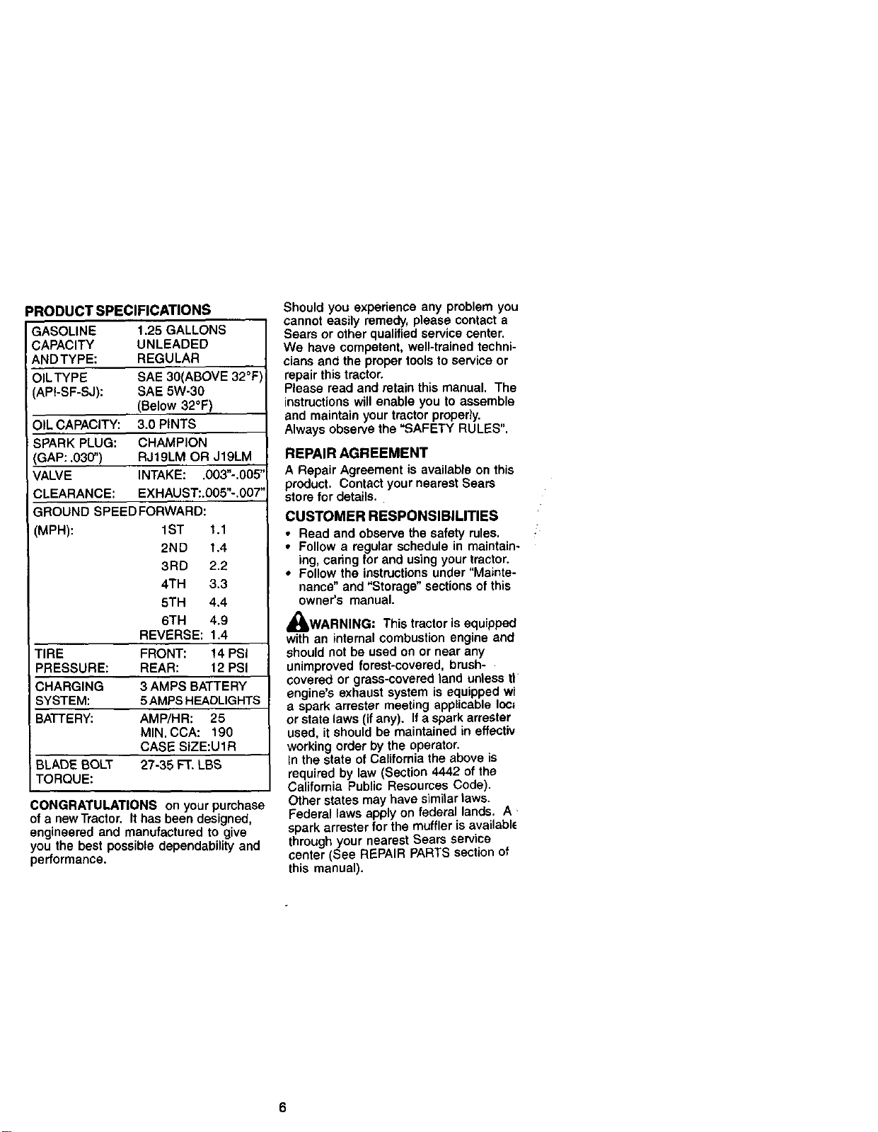
PRODUCTSPECIFICATIONS
GASOLINE 1.25GALLONS
CAPACITY UNLEADED
ANDTYPE: REGULAR
OILTYPE SAE30(ABOVE32°F
(API-SF-SJ): SAE5W-30
(Below32°F)
OILCAPACITY:3.0PINTS
SPARKPLUG: CHAMPION
GAP: .030") RJ19LM OR J19LM
VALVE INTAKE: .003"-.005"
CLEARANCE: EXHAUST:.005"-.007"
GROUND SPEEDFORWARD:
(MPH): 1ST 1.1
2ND 1.4
3RD 2.2
4TH 3.3
5TH 4.4
6TH 4.9
REVERSE: 1.4
TIRE FRONT: !4 PSi
PRESSURE: REAR: 12 PSI
CHARGING 3 AMPS BATTERY
SYSTEM: 5AMPS HEADLIGHTS
BATTERY: AMP/HR: 25
MIN. CCA: 190
CASE SIZE:U1R
BLADE BOLT 27-35 FT. LBS
TORQUE:
CONGRATULATIONS on your purchase
of a newTrector. It has been designed,
engineered and manufactured to give
you the best possible dependability and
performance.
Should you experience any problem you
cannot easily remedy, please contact a
Sears or other qualified service center.
We have competent, well-trained techni-
cians and the proper tools to service or
repair this tractor.
Please read and retain this manual. The
instructions will enable you to assemble
and maintain your tractor properly.
Always observe the "SAFETY RULES".
REPAIR AGREEMENT
A Repair Agreement is available on this
product. Contact your nearest Sears
store for details.
CUSTOMER RESPONSIBILITIES
• Read and observe the safety rules.
• Follow a regular schedule in maintain-
ing, oaring for and using your tractor.
• Follow the instructions under "Mainte-
nance" and "Storage" sections of this
owner's manual.
_I, WARNING: This tractor is equipped
with an internal combustion engine and
should not be used on or near any
unimproved forest-covered, brush-
covered or grass-covered land unless tl
engine's exhaust system is equipped wi
a spark arrester meeting applicable Ioc;
or state laws (ifany). If a spark arrester
used, it should be maintained in effectiv
working order by the operator.
In the state of California the above is
required by law (Section 4442 of the
California Public Resources Code).
Other states may have similar laws.
Federal laws apply on federal lands, A
spark arrester for the muffler is availabl_
through your nearest Sears service
center (See REPAIR PARTS section of
this manual).
6
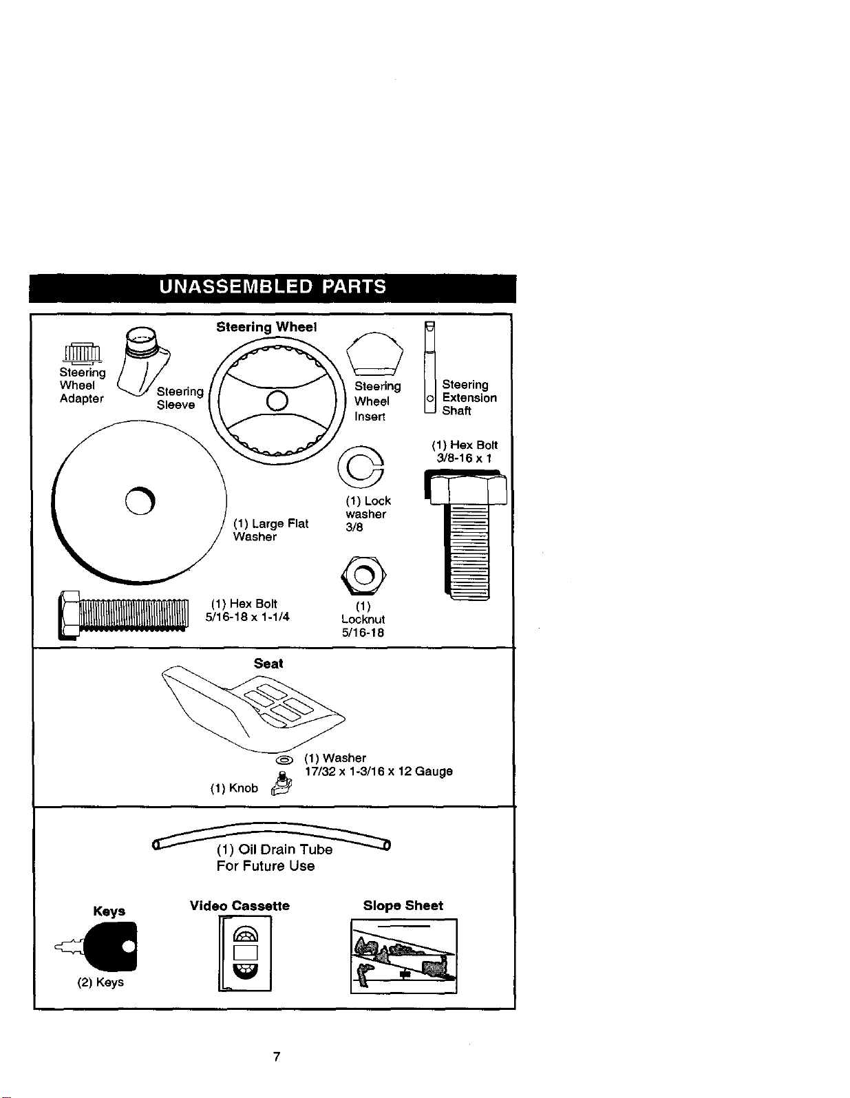
Steering
Wheel ering
Adapter Sleeve
Steering Wheel
Steering
Wheel
Insert
t Steering
Extension
Shaft
0
(1) Large Flat
Washer
(1) Hax Bolt
5/16-18 x 1-1/4
©
(1) Lock
washer
3/8
@
(1)
Locknut
5/16-18
(1) Hex Bolt
3/8-16 x 1
Seat
(1) Washer
(1)Knob _ 17132 x1-3/16 x12 Gauge
For Future Use
Keys
(2) Keys
Video Cassette
Slope Sheet
Yournewtractorhasbeen assembledat thefactorywit parts left
unassembledfor shippingpurposes.To ensuresafe and properoperationof your
tractorall parts and hardwareyouassemble mustbe tightenedsecurely.Use the
correcttoolsas necessarytoinsurepropertightness.Reviewthevideocassettebefore
you begin.
TOOLS REQUIRED FOR
ASSEMBLY
A socket wrench set will make assembly
easier. Standard wrench sizes you need
are listed below.
(1) 9/16" wrench (1) Pliers
(1) 1/2"wranch (1) Utility knife
(1) Tire pressure
gauge
When right or left hand is mentioned in
this manual, it means, from your point of
view, when you are in the operating
position (seated behind the steering
wheel).
TO REMOVETRACTOR FROM
CARTON
UNPACK CARTON
1. Remove all accessible loose parts
and parts cartons from carton.
2. Cut, from top to bottom, along lines
on all four comers of carton, and lay
panels flat.
3. Check for any additional loose parts
or cartons and remove.
BEFORE REMOVINGTRACTOR
FROM SKID
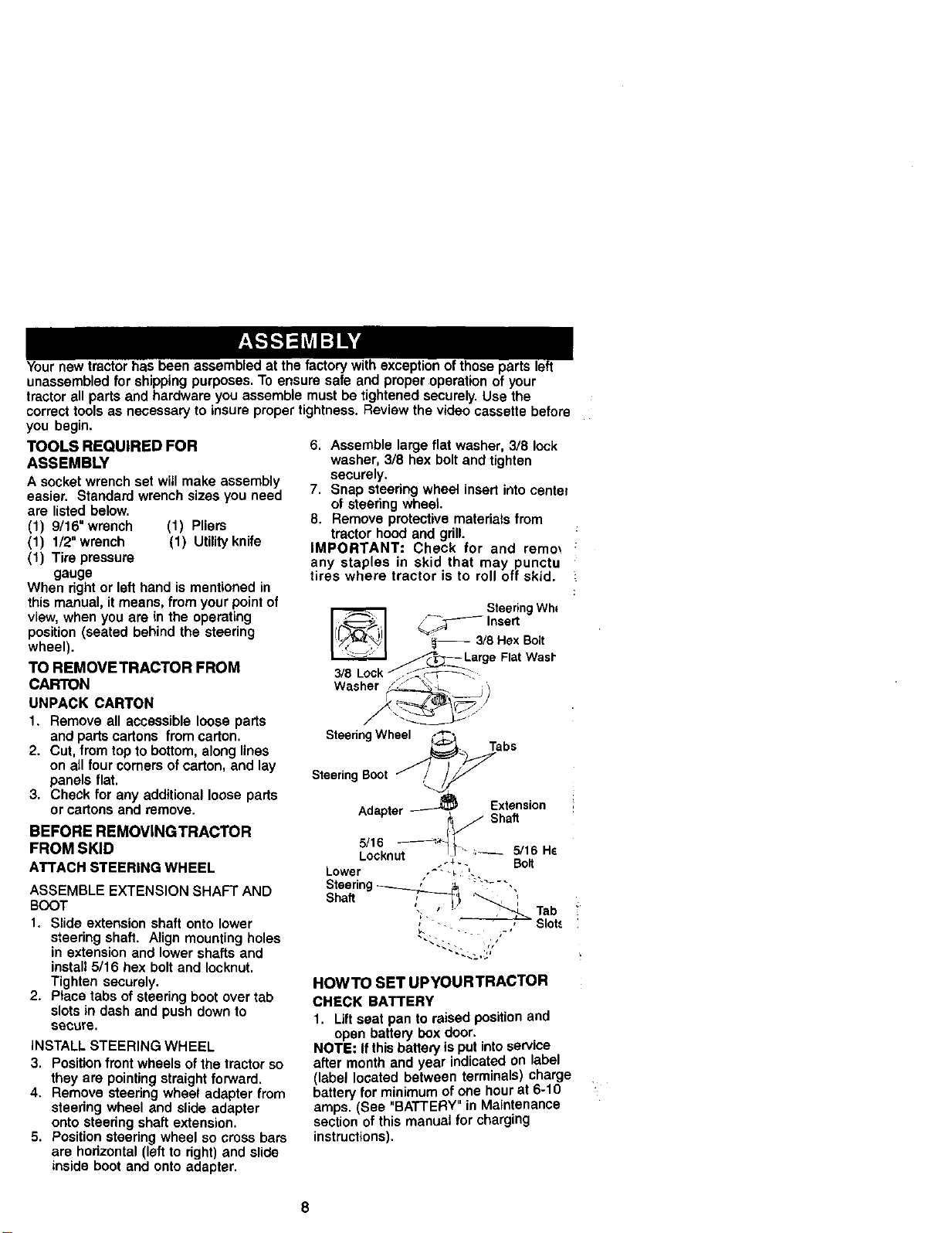
ATTACH STEERING WHEEL
ASSEMBLE EXTENSION SHAFT AND
BOOT
1. Slide extension shaft onto lower
steering shaft. Align mounting holes
in extension and lower shafts and
install 5/16 hex bolt and Iocknut.
Tighten securely.
2. Place tabs of steering boot over tab
slots in dash and push down to
sl_cure.
INSTALL STEERING WHEEL
3. Position front wheels of the tractor so
they are pointing straight forward.
4. Remove steering wheel adapter from
steering wheel and slide adapter
onto steedng shaft extension.
5. Position steering wheel so cross bars
are horizontal (left to right) and slide
inside boot and onto adapter.
6. Assemble large flat washer, 3/8 lock
washer, 3/8 hex bolt and tighten
securely.
7. Snap steering wheel insert into center
of steering wheel.
8. Remove protective materials from
tractor hood and grill.
IMPORTANT: Check for and remm
any staples in skid that may punctu
tires where tractor is to roll off skid.
3/8_Lock _ SteeringWh*
_._F Insert
_a/8 Hex Bolt
+,atWas,
SteeringWheel _*_
_';'_t,+ Tabs
SteeringBoot /__
Ada"ter _ Extension
" _ / Shaft
- - i_,-- 5116Hs
5116 -------_'_'
LOCKNUt _-+ +- Bolt
Lower ,+- ++ !.
Steering_ #_ _- ,,
, ' _ Tab
_-_ , , Slot,.
HOWTO SET UPYOURTRACTOR
CHECK BATTERY
1. Lift seat pan to raised position and
open battery box door.
NOTE: Ifthis battery is put into service
after month and year indicated on label
(label located between terminals) charge
battery for minimum of one hour at 6-10
amps. (See "BATTERY" in Maintenance
section of this manual for charging
instructions).
8
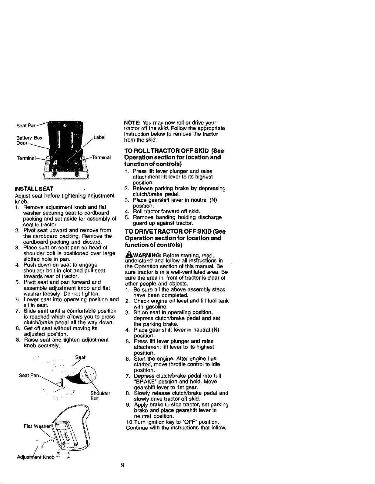
Ba_e_ Box
INSTALL SEAT
Adjust seat before tightening adjustment
knob.
1. Remove adjustment knob and flat
washer securing seat to cardboard
packing and set aside for assembly of
seat to tractor.
2. Pivot seat upward and remove from
the cardboard packing. Remove the
cardboard packing and discard.
3. Place seat on seat pan so head of
shoulder bolt is positioned over large
slotted hole in pan.
4, Push down on seat to engage
shoulder bolt in slot and pull seat
towards rear of tractor.
5. Pivot seat and pan forward and
assemble adjustment knob and flat
washer loosely. Do not tighten.
6. Lower seat into operating position and
sit in seat.
7. Slide seat until a comfortable position
is reached which allows you to press
clutch/brake pedal all the way down.
8. Get off seat without moving its
adjusted position.
8. Raise seat and tighten adjustment
knob securely.
Seat
J
/
Seat Pan _i
__i_'_ulder
Bolt
F,at
AdjustmentKnob=- =:_
NOTE: You may now roll or drive your
tractor off the skid, Follow the appropriate
instruction below to remove the tractor
from the skid.
TO ROLLTRACTOR OFF SKID (See
Operation section for location and
function of controls)
1. Press lift lever plunger and raise
attachment lift lever to its highest
position.
2. Release parking brake by depressing
clutch/brake pedal,
3. Place gearshift lever in neutral (N)
position.
4. Roll tractor forward off skid.
5. Remove banding holding discharge
guard up against tractor,
TO DRIVETRACTOR OFF SKID (See
Operation section for location and
function of controls)
_WARNING: Before starting, read,
understand and follow all instructions in
the Operation section of this manual. Be
sure tractor is in a well-ventilated area. Be
sure the area in front of tractor is clear of
other people and objects.
1. Be sure all the above assembly steps
have been completed.
2. Check engine oi! level and fill fuel tank
with gasoline.
3. Sit on seat in operating position,
depress clutch/brake pedal and set
the parking brake.
4. Place gear shift lever in neutral (N)
position.
5. Press lift lever plunger and raise
attachment lift lever to its highest
position.
6, Start the engine. After engine has
started, move throttle control to idle
position.
7. Depress clutch/brake pedal into full
"BRAKE" position and hold. Move
gearshift lever to Ist gear.
8, Slowly release clutch/brake pedal and
slowly ddve tractor off skid.
9. Apply brake to stop tractor, set parking
brake and place gearshift lever in
neutral position.
10.Turn ignition key to "OFF" position.
Continue with the instructions that follow.
9
CHECKTIRE PRESSURE
The tires on your tractor were overinflated
at the factory for shipping purposes.
Correct tire pressure is important for best
cutting performance.
• Reduce tire pressure to PSI shown in
"PRODUCT SPECIFICATIONS" section
of this manual.
CHECK DECK LEVELNESS
Forbestcuttingresults,mower housing
shouldbe propedyleveled. See "TO
LEVEL MOWER HOUSING"inthe
Serviceand Adjustmentssectionofthis
manual.
CHECK FOR PROPER POSITION OF
ALL BELTS
See the figures that are shown for
replacing motion and mower blade drive
belts in the Service and Adjustments
section ofthis manual. Verify that the
belts are routed correctly.
CHECK BRAKE SYSTEM
After you learn how to operate your
tractor, check to see that the brake is
properly adjusted. See "TO ADJUST
BRAKE" in the Service and Adjustments
section of this manual.
v_CHECKLIST
Before you operate and enjoy your new
tractor, we wish to assure that you receive
the best performance and satisfaction
from this Quality Product.
Please review the following checklist:
-,fAll assembly instructions have been
completed.
V"No remaining loose parts in carton.
.4"Battery is properly prepared and
charged. (Minimum 1 hour at 6 amps).
vSeat is adjusted comfortably and
tightened securely.
,,,tAil ti_'esare propedy inflated. (For
shipping purposes, the tires were
ovednflated at the factory).
v" Be sure mower deck is properly leveled
side-to-side/front-to-rear for best cutting
results. (Tires must be propedy inflated
for leveling).
,/'Check mower and drive belts. Be sure
they are routed propedy around pulleys
and inside all belt keepers.
,/'Check wiring. See that all connections
are still secure and wires are prapedy
clamped.
While learning how to use your tractor,
pay extra attention to the following
important items:
v" Engine oil is at proper level.
V"Fuel tank is filled with fresh, clean,
regular unleaded gasoline.
v"Become familiar with all controls - their
location and function. Operate them
before you start the engine.
.,/Be sure brake system is in safe
operating condition.
10
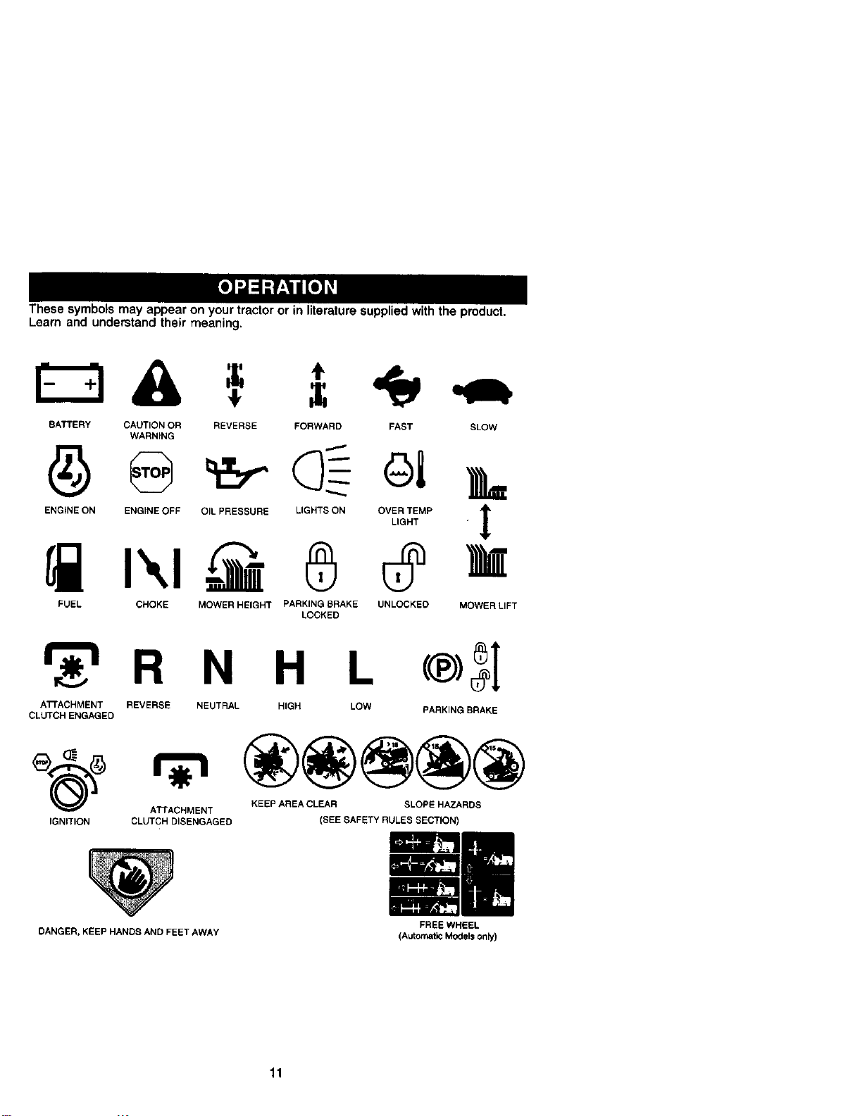
These symbols may appear on your tractor or in literature supplied with the product.
Learn and understand their meaning.
A, =
BATTERY CAUTION OR
WARNtNG
ENGINE ON ENGINE OFF
REVERSE FORWARD FAST SLOW
FUEL CHOKE
OIL PRESSURE LIGHTS ON OVER TEMP
LIGHT
1
00=
MOWER HEIGHT PARKING BRAKE UNLOCKED MOWER LIFT
LOCKED
_r_'l R N H L c®)_I
ATTACHMENT REVERSE NEUTRAL HIGH LOW PARKING BRAKE
CLUTCH ENGAGED
_(_) ATTACHMENT KEEP AREA CLEAR SLOPE HAZARDS
IGNITION CLUTCH DISENGAGED (SEE SAFETY RULES SECTION)
DANGER, KEEP HANDS AND FEET AWAY
11
FREE WHEEL
(Automatic Models only)
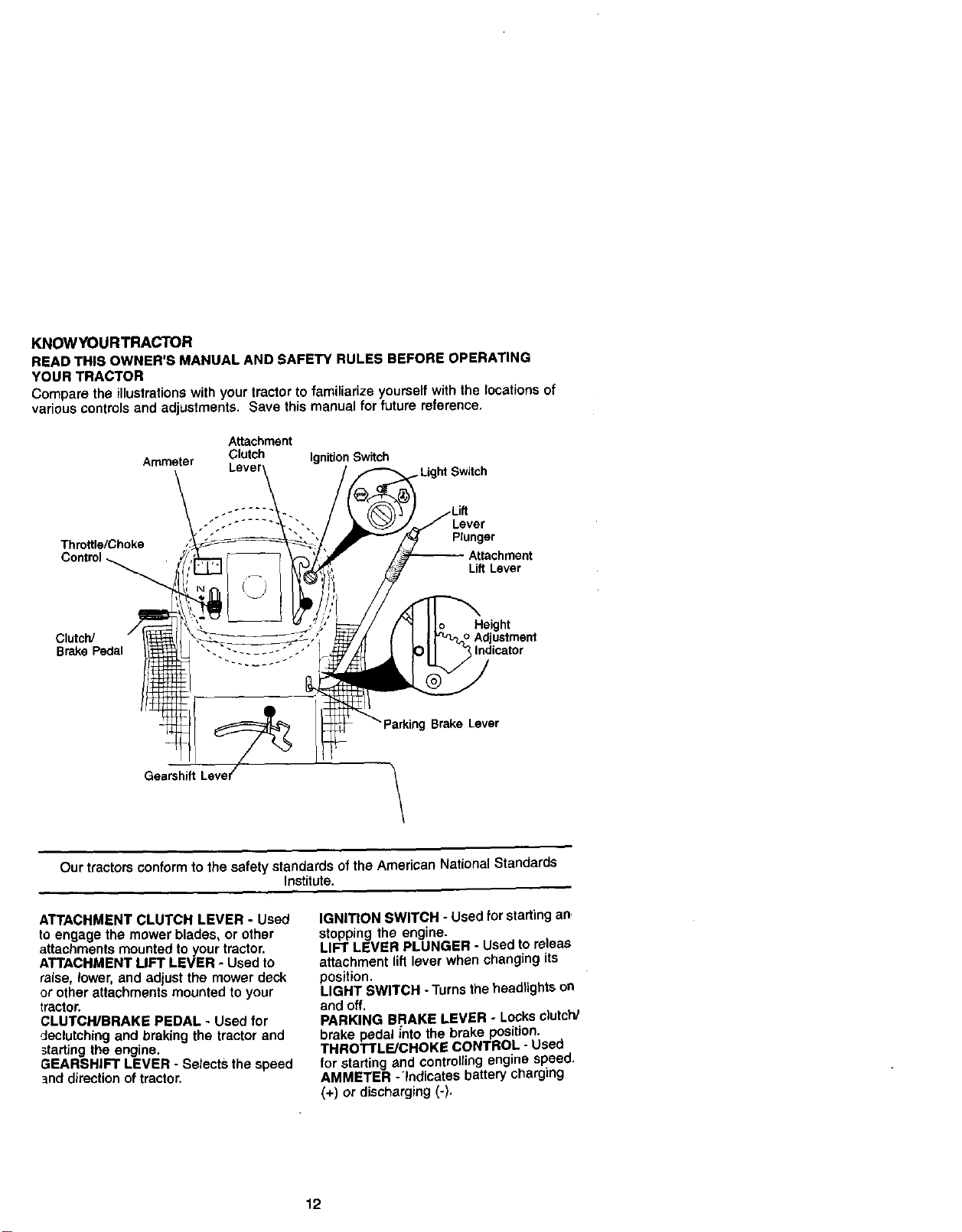
KNOWYOURTRACTOR
READ THIS OWNER'S MANUAL AND SAFETY RULES BEFORE OPERATING
YOUR TRACTOR
Compare the illustrations with your Iractor to familiarize yourself with the locations of
various controls and adjustments. Save this manual for future reference.
Ammeter
Attachment
Clutch Ignition Switch
," .- Lever
Thro_le/Choke Plunger
Control Attachment
LiftLever
Height
Clutch/ Adjustment
BrakePedal Indicator
Brake Lever
Gearshift
\
Our tractors conform to the safety standards of the American National Standards
Institute.
ATTACHMENT CLUTCH LEVER - Used
to engage the mower blades, or other
attachments mounted to your tractor.
ATTACHMENT LIFT LEVER - Used to
raise, lower, and adjust the mower deck
or other attachments mounted to your
tractor.
CLUTCH/BRAKE PEDAL - Used for
declutching and braking the tractor and
starting the engine.
GEARSHIFT LEVER - Selects the speed
"_nddirection of tractor.
IGNITION SWITCH - Used for starting an,
stopping the engine.
LIFT LEVER PLUNGER - Used to releas
attachment lift lever when changing its
position.
LIGHT SWITCH -Turns the headtights on
and off.
PARKING BRAKE LEVER - Locks clutch/
brake pedal into the brake position.
THROTTLE/CHOKE CONTROL - Used
for starting and controlling engine speed.
AMMETER -Indicates battery charging
(+) or discharging (-).
12
The operation of any tractor can result in foreign objects thrown into
the eyes, which can result in severe eye damage. Always wear safety
glasses or eye shields while operating your tractor or performing any
adjustments or repairs. We recommend a wide vision safety mask
over spectacles or standard safety glasses.
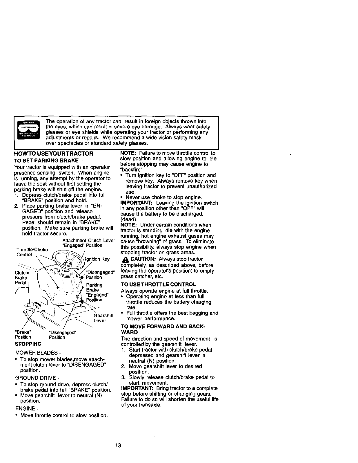
HOWTO USEYOURTRACTOR
TO SET PARKING BRAKE
Your tractor is equipped with an operator
presence sensing switch. When engine
is running, any attempt by the operator to
leave the seat without first setting the
parking brake will shut off the engine.
1. Depress clutch/brake pedal into full
"BRAKE" position and hold.
2. Place parking brake lever in "EN-
GAGED" position and release
pressure from clutch/brake pedal.
Pedal should remain in "BRAKE"
position. Make sure parking brake will
hold tractor secure.
AttachmentClutch Lever
"Engaged" Position
Thrn_ttlrc_'Cheke .-":_'---/F_.._._/
Clutch__' __/'_Disengaged"
Brake _ _f, '_;_e(Position
PedalI _ _ '__'_. Parking
' I _ : ...... _/\ Engaged
_ F?_._ Gearshift
_/i_Lever
"Brake" _Disengaged'
Position Position
STOPPING
MOWER BLADES -
• To stop mower blades,move attach-
ment clutch lever to "DISENGAGED"
position.
GROUND DRIVE -
• To stop ground drive, depress clutch/
brake pedal into full "BRAKE" position.
• Move gearshift lever to neutral (N)
position.
ENGINE -
NOTE: Failure to move throttle control to
slow position and allowing engine to idle
before stopping may cause engine to
"backfire".
•Tum ignition key to "OFF" position and
remove key. Always remove key when
leaving tractor to prevent unauthorized
use,
• Never use choke to stop engine.
IMPORTANT: Leaving the ignition switch
in any position other than "OFF" will
cause the battery to be discharged,
(dead).
NOTE: Under certain conditions when
tractor is standing idle with the engine
running, hot engine exhaust gases may
cause "browning" of grass. To eliminate
this possibility, always stop engine when
stopping tractor on grass areas.
CAUTION: Always stop tractor
completely, as described above, before
leaving the operator's position; to empty
grass catcher, etc.
TO USE THROTTLE CONTROL
Always operate engine at full throttle.
• Operating engine at less than full
throttle reduces the battery charging
rate.
• Full throttle offers the best bagging and
mower performance.
TO MOVE FORWARD AND BACK-
WARD
The direction and speed of movement is
controlled by the gearshift lever.
1. Start tractor with clutch/brake pedal
depressed and gearshift lever in
neutral (N) position.
2. Move gearshift lever to desired
position.
3. Slowly release clutch/brake pedal to
start movement.
IMPORTANT: Bring tractor to a complete
stop before shifting or changing gears.
Failure to do so will shorten the useful life
of your transaxle.
• Move throttle control to slow position.
13
TO ADJUST MOWER CUTTING HEIGHT
The position of the attachment lift lever
determines the cutting height.
• Grasp lift lever.
• Press plunger with thumb and move
lever to desired position.
The cutting height range is approxi-
mately 1-1/2 to 4". The heights are
measured from the ground to the blade
tip with the engine not running. These
heights are approximate and may vary
depending upon soil conditions, height of
grass and types of grass being mowed.
• The average lawn should be cut to
approximately 2-1/2 inches dudng the
cool season and to over 3 inches
during hot months. For healthier and
better looking lawns, mow often and
after moderate growth.
• For best cutting performance, grass
over 6 inches in height should be
mowed twice. Make the first cut
relatively high; the second to desired
height.
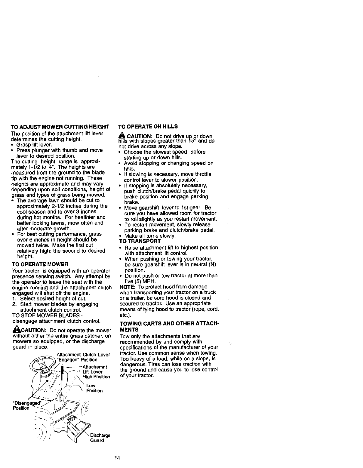
TO OPERATE MOWER
Your tractor is equipped with an operator
presence sensing switch. Any attempt by
the operator to leave the seat with the
engine running and the attachment clutch
engaged will shut off the engine.
1. Select desired height of cut.
2. Start mower blades by engaging
attachment clutch control.
TO STOP MOWER BLADES -
disengage attachment clutch control.
_Ib,CAUTION: Do not operate the mower
without either the entire grass catcher, on
mowers so equipped, or the discharge
guard in place.
AttachmentClutchLever
"Engaged" Position
f, Lift Lever
High Position
Low
Position
TO OPERATE ON HILLS
_, CAUTION: Do not drive up or down
hills with slopes greater than 15° and do
not drive across any slope.
• Choose the slowest speed before
starting up or down hills.
• Avoid stopping or changing speed on
hills.
• If slewing is necessary, move throttle
control lever to slower position.
• If stopping is absolutely necessary,
push clutch/brake pedal quickly to
brake position and engage parking
brake.
• Move gearshift lever to 1st gear. Be
sure you have allowed room for tractor
to roll slightly as you restart movement.
• To restart movement, slowly release
parking brake and clutcl'Vbrake pedal.
• Make all turns slowly.
TO TRANSPORT
• Raise attachment liftto highest position
with attachment lift control.
• When pushing or towing your tractor,
be sure gearshift lever is in neutral (N)
position.
• Do not push or tow tractor at more than
five (5) MPH.
NOTE: To protect hood from damage
when transporting your tractor on a truck
or a trailer, be sure hood is closed and
secured to tractor. Use an appropriate
means of tying hood to tractor (rope, cord,
etc.).
TOWING CARTS AND OTHER ATTACH-
MENTS
Tow only the attachments that are
recommended by and comply with
specifications of the manufacturer of your
tractor. Use common sense when towing.
Too heavy of a load, while on a slope, is
dangerous. Tires can lose traction with
the gmund and cause you to lose control
of your tractor.
Guard
14
BEFORE STARTINGTHE ENGINE
CHECK ENGINE OIL LEVEL
The engine in your tractor has been
shipped, from the factory, already filled
with summer weight oil
1. Check engine oil with tractor on level
ground.
2. Remove oil fill cap/dipstick and wipe
clean, reinsert the dipstick and screw
cap tight, wait for a few seconds,
remove and read oil level. If neces-
san], add oil until "FULU' mark on
dipstick is reached. Do not overfill.
• For cold weather operation you should
change oil for easier starting (See "OIL .
VISCOSITY CHART" in the Mainte-
nance section of this manual).
• To change engine oil, see the Mainte-
nance section in this manual.
ADD GASOLINE
• Fill fuel tank. Use fresh, clean, regular
unleaded gasoline with a minimum of
• 87 octane. (Use of leaded gasoline
will increase carbon and lead oxide
deposits and reduce valve tile). Do not
mix oil with gasoline. Purchase fuel in
quantities that can be used within 30
days to assure fuel freshness.
IMPORTANT: When operating in
temperatures below 32°F(0°C), use fresh,
clean winter grade gasoline to help
insure good cold weather starting.
_I, WARNING: Experience indicates that
alcohol blended fuels (called gasohol or
using ethanol or methanol) can attract
moisture which leads to separation and
formation of acids during storage. Acidic
gas can damage the fuel system of an
engine while in storage. To avoid engine
problems, the fuel system should be
emptied before storage of 30 days or
longer. Drain the gas tank, start the
engine and let it run until the fuel lines
and carburetor are empty. Use fresh fuel
next season. See Storage instructions for
additional information. Never use engine
or carburetor cleaner products in the fuel
tank or permanent damage may occur.
,.._.CAUTION: Fillto bottom of gas tank
tiller neck. Do notoverfill. Wipe off any
spilled oil or fuel. Do not store, spill or
use gasoline near an open flame.
TO START ENGINE
When startingthe engine forthe firsttimeor if
the enginehas runoutoffuel, itwilltake extra
crankingtime to move fuel from the tankto
the engine.
1. Sit on seat in operating position,
depress clutch/brake pedal and set
parking brake.
2. Place gear shift lever in neutral (N)
position.
3. Move attachment clutch to "DISEN-
GAGED" position.
4. Move throttle control to choke position.
NOTE: Before starting,readthe warm and
cold startingproceduresbelow.
5. Insert key into ignition and turn key
clockwise to "START" position and
release key as soon as engine starts.
Do not run starter continuously for
more than fifteen seconds per minute,
Ifthe engine does not start after
several attempts, move throttle control
to fast position, wait a few minutes and
try again. If engine still does not start,
move the throttle control back to the
choke position and retry.
WARM WEATHER STARTING (50° F and
above)
6. When engine starts, move the throttle
control to the fast position.
• The attachments and ground drive can
now be used. If the engine does not
accept the load, restart the engine and
allow it to warm up for one minute
using the choke as described above.
COLD WEATHER STARTING (50° F and
below)
6. When engine starts, allow engine to
run with the throttle control in the
choke position until the engine runs
roughly, then move throttle control to
fast position. This may require an
engine warm-up period from several
seconds to several minutes, depend-
ing on the temperature.
• The attachments can also be used
during the engine warm-up period.
NOTE: Ifat a highaltitude(above 3000 feet)
or in cold tam!_ratures (below 32 F) the
carburetorfuel mixturemay need tobe
adjustedfor best engine performance.See
"ro ADJUST CARBURETOR" inthe Service
and Adjustmentssectionofthis manual.
15
MOWINGTIPS
• Tire chains cannot be used when the
mower housing is attached to tractor.
• Mower should be propedy leveled for
best mowing performance. See "TO
LEVEL MOWER HOUSING" in the
Service and Adjustments section of this
manual.
• The left hand side of mower should be
used for tdmming.
• Drive so that clippings are discharged
onto the area that has been cut. Have
the cut area to the right of the tractor.
This will result in a more even distdbu-
tion of clippings and more uniform
cutting.
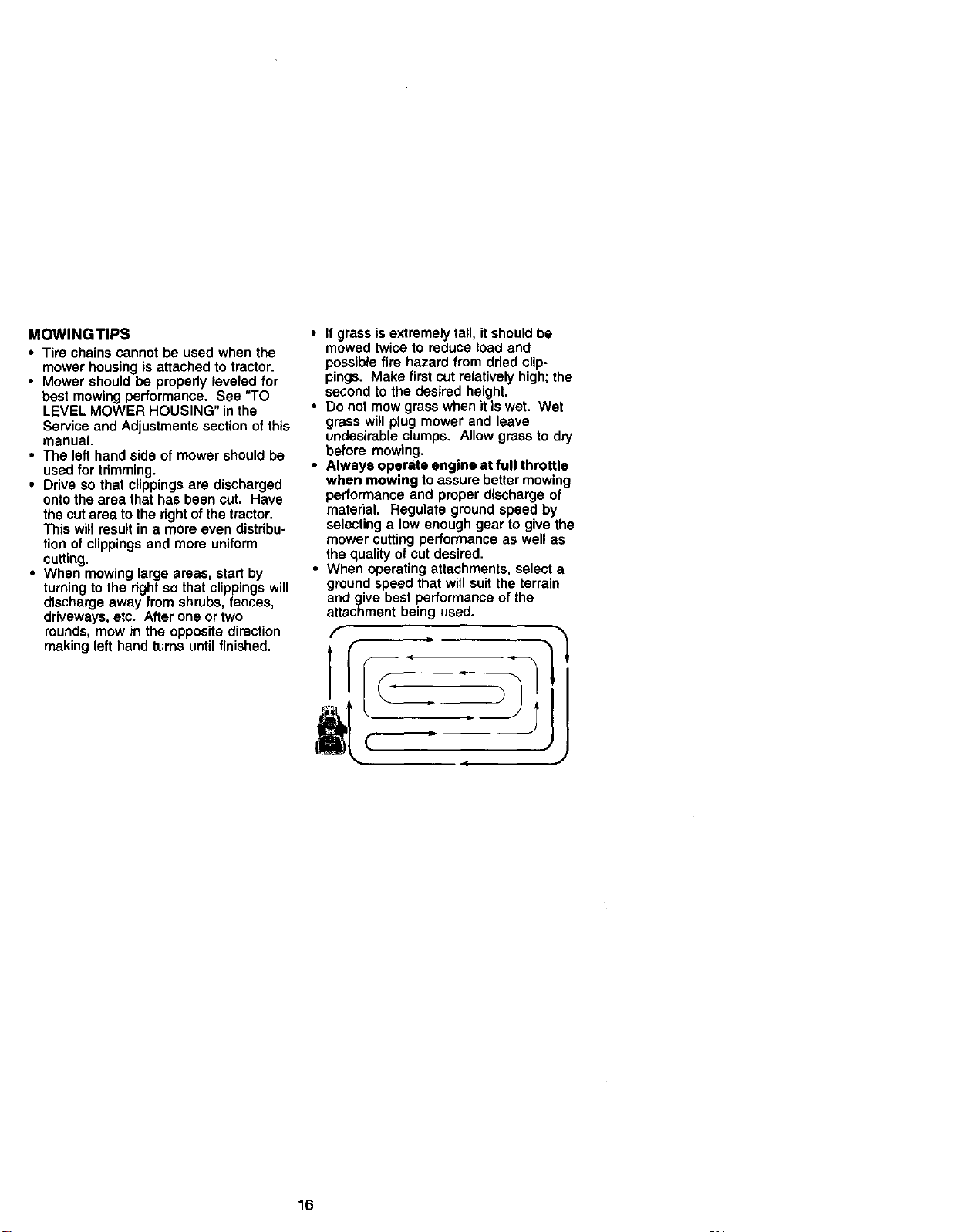
• When mowing large areas, start by
turning to the dght so that clippings will
discharge away from shrubs, fences,
driveways, etc. After one or two
rounds, mow in the opposite direction
making left hand turns until finished.
• If grass is extremely tall, it should be
mowed twice to reduce load and
possible fire hazard from dried clip-
pings. Make first cut relatively high; the
second to the desired height.
• Do not mow grass when it is wet. Wet
grass will plug mower and leave
undesirable clumps. Allow grass to dry
before mowing.
• Always operate engine at full throttle
when mowing to assure better mowing
performance and proper discharge of
material. Regulate ground speed by
selecting a low enough gear to give the
mower cutting performance as well as
the quality of cut desired.
• When operating attachments, select a
ground speed that will suit the terrain
and give best performance of the
attachment being used.
f
t
J
J
16

MAINTENANCESCHEDULE/__"_,,__ _ _ _ _ I
FILL IN DATES /__ S____" DATES I
AS YOU COMPLETE
REGULAR SERVICE
M MCheck Brake OPeratio_
I CheCk Tire Pressure
Check Operator Presence and
TR Ir_erlock Syste_'_$ M
ChickforLooU_Famne_s It/ Mr M
sharpen/Replace Mower Blades fl/4
LU_at_c_. V' I/
oT CheckBatteryLevel f_,
a ck3an Battery and Terminals M
C_ck Tra_,_xle COoling M
AdjustBladeRelt(s)Tens_ Ms
tcljusl Motion Drive Belt(s) Tension _#s
l
Check Engi_,eOil Level Id/ M
char_ ErlgiP.e Oil _1=.3 M
i clean AirFilter Me
Clean Air Screen II_
Ip._l_ M uffler/_oGr_ Affesler M
Replace Oil Flit er (ff equipped) I_1:
N Clean Engine Cooling Fk'.s M=
Replace Spark Plug M I_
Replace Air Filter Paper Cartddge M_
Replace Fuel Filter M I
I . Change mote olten wbl_ O_lr alklg undO: a hecvy k_adot In high_ _mpera_r e$ 5 - tl ¢._Jlppld w_t adlt_lab_ I_'tlrq
2. Service n_e o;t_ wh_ op_allng _ dirtyor dusly ¢¢r,)l_r_s
3 t;equlpFed wlt_ ol ,,_t. charge ol ev_y SO hc_r_
4 R_l_Ce blades n _re otmn wheft mONklg In Mno_ Sod
GENERAL RECOMMENDATIONS
The warranty on this tractor does not
cover items that have been subjected to
operator abuse or negligence. To receive
full value from the warranty, operator must
maintain tractor as instructed in this
manual.
Some adjustments will need to be made
periodically to properly maintain your
tractor.
All adjustments in the Service and
Adjustments section of this manual
should be checked at least once each
season.
• Once a year you should replace the
spark plug, clean or replace air filter,
and check blades and belts for wear. A
new spark plug and clean air filter
assure proper air-fuel mixture and help
your engine run better and last longer.
BEFORE EACH USE
1. Check engine oil level.
2. Check brake operation.
3. Check tire pressure.
4. Check operator presence and
interlock systems for proper operation.
5. Check for toose fasteners.
h_ re_r_ Ifequ_,p_i_,lh r_ balt.rf.
7 TightenbOnl_le IdVO_boit"03_fl-Ibsrel_'a_m,
LUBRICATION CHART
(_ Spindle
Zerk Zerk
(_Front Wheel
Bearing
Zerk
i
: : [ i
q_SAE OR I0W30 MOTOR OIL
_REFER TO MAINTENANCE"ENGINE"
SECTION
IMPORTANT: DO not oil or grease the
pivot points which have special nylon
bearings, Viscous lubricants will attract
dust and dirt that will shorten the life of
the self-lubricating bearings. If you feel
they must be lubncated, use only a dry,
powdered graphite type lubricant
BesdngZe_
17sparingly'
TRACTOR
Always observe safety rules when
performing any maintenance.
BRAKE OPERATION
If tractor requires more than six (6) feet
stopping distance at high speed in
highest gear, then brake must be ad-
justed. (See TO ADJUST BRAKE" in the
Service and Adjustments section of this
manual).
TIRES
• Maintain proper air pressure in all tires
(See "PRODUCT SPECIFICATIONS"
section of this manual).
• Keep tires free of gasoline, oil, or insect
control chemicals which can harm
rubber.
• Avoid stumps, stones, deep ruts, sharp
objects and other hazards that may
cause tire damage.
NOTE: To seal tire punctures and prevent
flat tires due to slow leaks, tire sealant
may be pumhased from your local parts
dealer. Tire sealant also prevents tire dry
rot and corrosion.
OPERATOR PRESENCE SYSTEM
Be sure operator presence and interlock
systems are working properly. If your
tractor does not function as described,
repair the problem immediately.
• The engine should not start unless the
clutch/brake pedal is fully depressed
and attachement clutch control is in the
disengaged position.
• When the engine is running, any
attempt by the operator to leave the
seat without first setting the parking
brake should shut off the engine.
• When the engine is running and the
attachment clutch is engaged, any
attempt by the operator to leave the
seat should shut off the engine.
• The attachment clutch should never
operate unless the operator is in the
seat.
BLADE CARE
For best results mower blades must be
kept sharp. Replace bent or damaged
blades.
BLADE REMOVAL
1. Raise mower to highest position to
allow access to blades.
2. Remove hex bolt, lock washer and flat
washer securing blade.
18
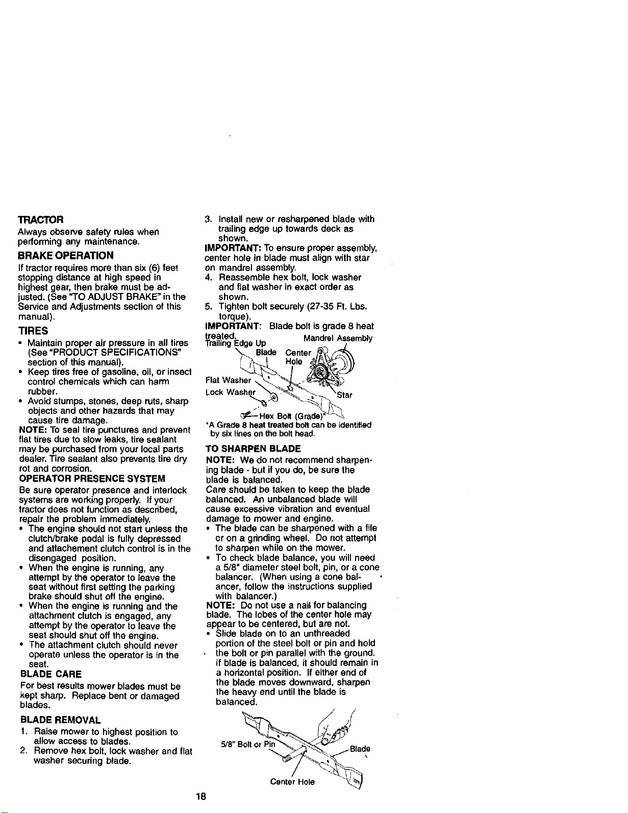
3. Install new or resharpened blade with
trailing edge up towards deck as
shown.
IMPORTANT: To ensure proper assembly,
center hole in blade must align with star
on mandrel assembly.
4. Reassemble hex bolt, lock washer
and flat washer in exact order as
shown.
5. Tighten bolt securely (27-35 Ft. Lbs.
torque).
IMPORTANT: Blade bolt is grade 8 heat
treated. MandrelAssembly
TrailingI Up
Blade Center
Hole
Flat Washer,
Lock Washer
_--Hex Bol (I
*A Grade 8 heat_eated boltcanbeident_ied
by sixlines onthebolthead.
TO SHARPEN BLADE
NOTE: We do not recommend sharpen-
ing blade - but ifyou do, be sure the
blade is balanced.
Care should be taken to keep the blade
balanced. An unbalanced blade will
cause excessive vibration and eventual
damage to mower and engine.
• The blade can be sharpened with a file
or on a grinding wheel. Do not attempt
to sharpen while on the mower.
• To check blade balance, you will need
a 5/8" diameter steel bolt, pin, or a cone
balancer. (When using a cone bal-
ancer, follow the instructions supplied
with balaocer.)
NOTE: Do not use a nail for balancing
blade. The lobes of the center hole may
appear to be centered, but are not.
• Slide blade on to an unthreaded
portion of the steel bolt or pin and hold
the bolt or pin parallel with the ground.
if blade is balanced, it should remain in
a horizontal position. If either end of
the blade moves downward, sharpen
the heavy end until the blade is
balanced.
5/8 'p
Center Hole
BATTERY
Yourtractorhasa battery charging system
which is sufficient for normal use. How-
ever, periodic charging of the battery with
an automotive charger will extend its life,
• Keep battery and terminals clean.
• Keep battery bolts tight.
• Keep small vent ho_es open.
• Recharge at 6-10 amperes for 1 hour.
NOTE: The original equipment battery on
your tractor is maintenance free, Do not
attempt to open or remove caps or covers.
Adding or checking level of electrolyte is
not necessary.
TO CLEAN BATTERY ANDTERMINALS
Corrosion and dirt on the battery and
terminals can cause the battery to "leak"
power.
1. Open battery box door.
2. Disconnect BLACK battery cable fimt
then RED batte_ cable and remove
battery from tractor.
3. Rinse the battery with plain water and
dry.
4. Clean terminals and battery cable
ends with wire brush until bright.
5. Coat terminals with grease or petro-
leum jelly.
6. Reinstall battery (See "REPLACING
BATTERY" in the SERVICE AND
ADJUSTMENTS section of this
manual),
V-BELTS
Check V-belts for deterioration and wear
after 100 hours of operation and replace
ifnecessary. The belts are not adjustable.
Replace baits if they begin to slip from
wear.
TRANSAXLE COOLING
Keep transaxle free from build-up of dirt
and chaff which can restrict cooling.
ENGINE
LUBRICATION
Onty use high quality detergent oil rated
with API service classification SF-SJ
Select the oil's SAE viscosity grade
according to your expected operating
temperature.
NOTE: Although multi-viscosity oils
(5W30, 10W30 etc,) improve starting in
cold weather, these multi-viscosity oils
will result in increased oi! consumption
when used above 32°F. Check your
engine oil level more frequently to avoid
possible engine damage from running
low on oil,
Change the oil after every 25 hours of
operation or at least once a year if the
tractor is not used for 25 hours In one
year.
Check the crankcase oil level before
starting the engine and after each eight
(8) hours of operation. Tighten oil fill cap/
dipstick securely each time you check the
oil level.
TO CHANGE ENGINE OIL
Determine temperature range expected
before oil change. All oil must meet API
service classification SF-SJ.
• Be sure tractor is on level surface.
• Oil will drain more freely when warm.
• Catch oil in a suitable container.
1. Remove oil fill cap/dipstick. Be careful
not to allow dirt to enter the engine
when changing oil.
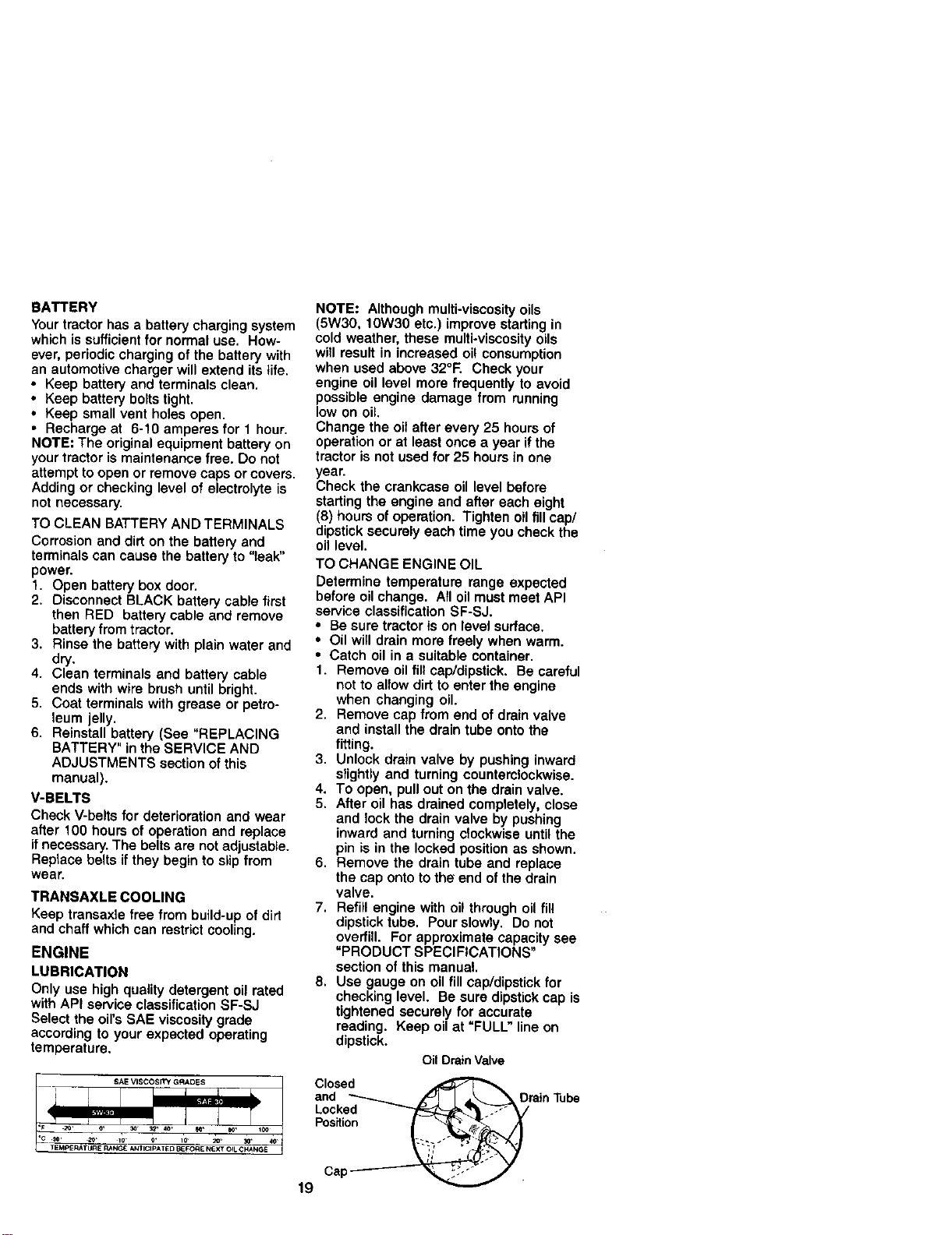
2. Remove cap from end of drain valve
and install the drain tube onto the
fitting.
3. Unlock drain valve by pushing inward
slightly and turning counterclockwise.
4. To open, pull out on the drain valve.
5. After oil has drained completely, close
and lock the drain valve by pushing
inward and turning clockwise until the
pin is in the locked position as shown.
6, Remove the drain tube and replace
the cap onto to the end of the drain
valve.
7, Refill engine with oil through oil fill
dipstick tube. Pour slowly. Do not
overfill. For approximate capacity see
"PRODUCT SPECIFICATIONS"
section of this manual.
8. Use gauge on oil fill cap/dipstick for
checking level. Be sure dipstick cap is
tightened securely for accurate
reading. Keep oil at "FULL" line on
dipstick.
Oil DrainValve
Closed
and _ _'_Jl I _.._-_ _ Drain Tube
Locked _'_F_[E_'-_"_.,--" V
Position
Cap _ _
19
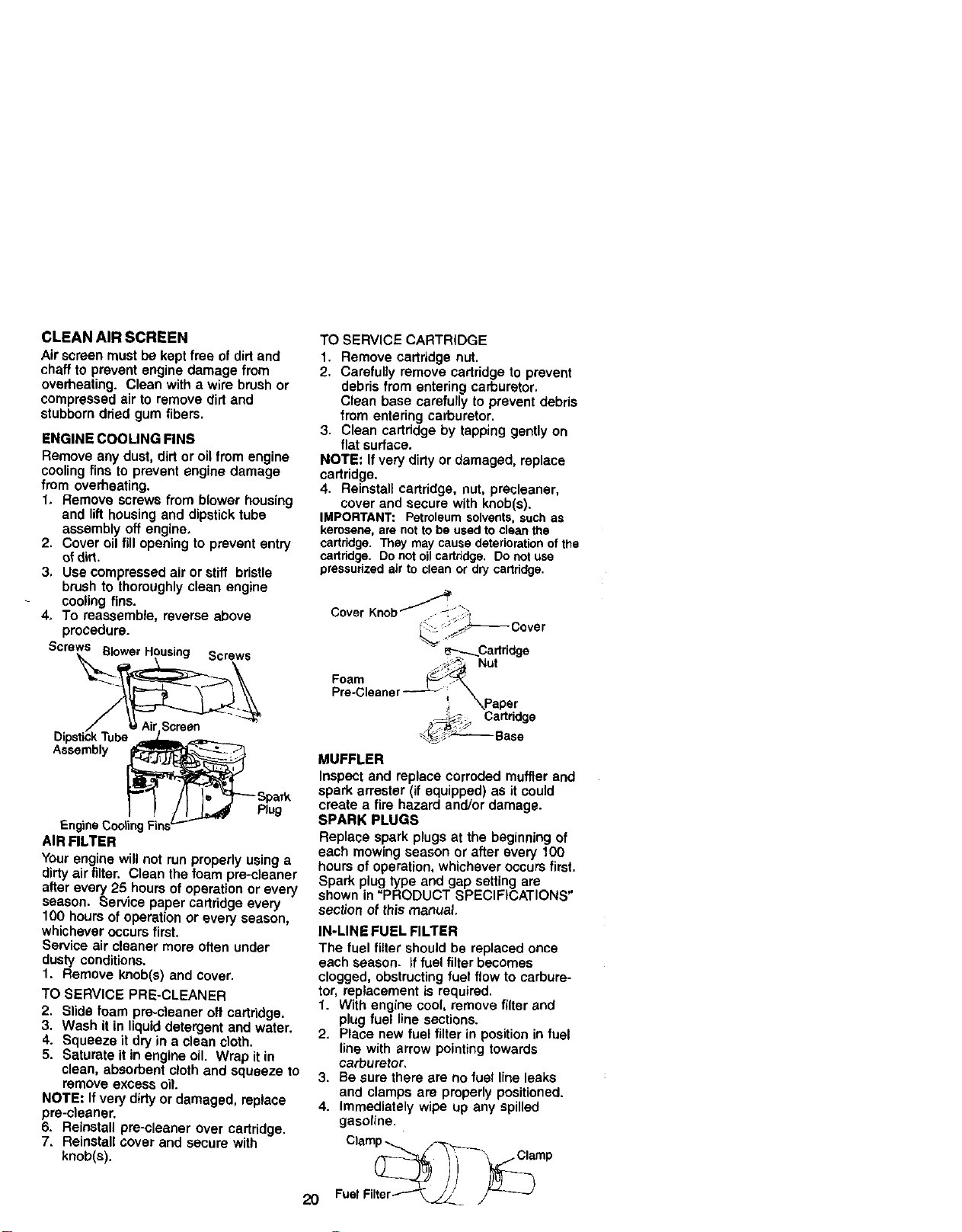
CLEANAIRSCREEN
Airscreenmustbekeptfree of dirt and
chaff to prevent engine damage from
overheating. Clean with a wire brush or
compressed air to remove dirt and
stubborn dded gum fibers.
ENGINE COOLING FINS
Remove any dust, dirt or oil from engine
cooling fins to prevent engine damage
from overheating.
1. Remove screws from blower housing
and lift housing and dipstick tube
assembly off engine,
2, Cover oil fill opening to prevent entry
of dirt.
3, Use compressed air or stiff bristle
brush to thoroughly clean engine
cooling fins.
4, To reassemble, reverse above
procedure.
Screws Btower Housing Screws
Assembly
Plug
F-nglnet;ooling
AIR FILTER
Your engine will not run properly using a
dirty air filter. Clean the foam pre-deaner
after every 25 hours of operation or every
season. Service paper cartridge every
100 hours of operation or every season,
whichever occurs first.
Service air cleaner more often under
dusty conditions.
1. Remove knob(s) and cover.
TO SERVICE PRE-CLEANER
2. Slide foam pre-cieaner off cartridge.
3. Wash it in liquid detergent and water.
4, Squeeze it dryin a dean cloth.
5. Saturate it in engine oil. Wrap it in
clean, absorbent cloth and squeeze to
remove excess oit.
NOTE: If very dirty or damaged, replace
pre-cleaner.
6. Reinstall pre-cleaner over cartridge.
7, Reinstall cover and secure with
knob(s).
TO SERVICE CARTRIDGE
1. Remove cartridge nut.
2. Carefully remove cartridge to prevent
debris from entering carburetor.
Clean base carefully to prevent debris
from entering carburetor.
3. Clean cartridge by tapping gently on
flat surface.
NOTE: If very dirty or damaged, replace
cartridge.
4. Reinstall cartridge, nut, precleaner,
cover and secure with knob(s).
IMPORTANT: Petroleumsolvents,such as
kerosene,are nottobe usedto clean the
cartridge. Theymay causedeteriorationofthe
cartddge. DOnotoil cartridge. Donotuse
pressurizedairto cleanor drycartridge.
2O
Cover _ _----_ Cover
FT---.-_Cartridge
._,_:_ Nut
Foam _';_
Pre-Gleaner --- _ X
_j \Paper
__ Cartridge
_-._3_ Base
MUFFLER
Inspect and replace corroded muffler and
spark arrester (if equipped) as it could
create a fire hazard and/or damage.
SPARK PLUGS
Replace spark plugs at the beginning of
each mowing season or after every 100
hours of operation, whichever occurs first.
Spark plug type and gap setting are
shown in "PRODUCT SPECIFICATIONS"
section of this manual.
IN-LINE FUEL FILTER
The fuel filter should be replaced once
each season, if fuel filter becomes
clogged, obstructing fuel flow to carbure-
tor, replacement is required.
1. With engine cool, remove filter and
plug fuel line sections.
2. Place new fuel filter in position in fuel
line with arrow pointing towards
carburetor,
3. Be sure there are no fuel line leaks
and clamps are properly positioned.
4. immediately wipe up any spilled
gasoline.
Clamp-_
Fua, i,er _
CLEANING
i Clean engine, battery, seat, finish, etc.
of all foreign matter.
Keep finished surfaces and wheels free
of all gasoline, oil, etc,
• Protect painted surfaces with automo-
tive type wax.
We do not recommend using a garden
hose to clean your tractor unless the
electrical system, muffler, air filter and
carburetor are covered to keep water out.
Water in engine can result in a shortened
engine life.
A
CAUTION: BEFORE PERFORMING ANY SERVICE OR ADJUSTMENTS:
1. Depress clutch/brake pedal fully and set parking brake.
2. Place gearshift lever in neutral (N) position.
3. Place attachment clutch in "DISENGAGED" position.
4. Turn ignition key "OFF" and remove key.
5. Make sure the blades and all moving parts have completely stopped.
6. Disconnect spark plug wire from spark plug and place wire where it cannot
come in contact with plug.
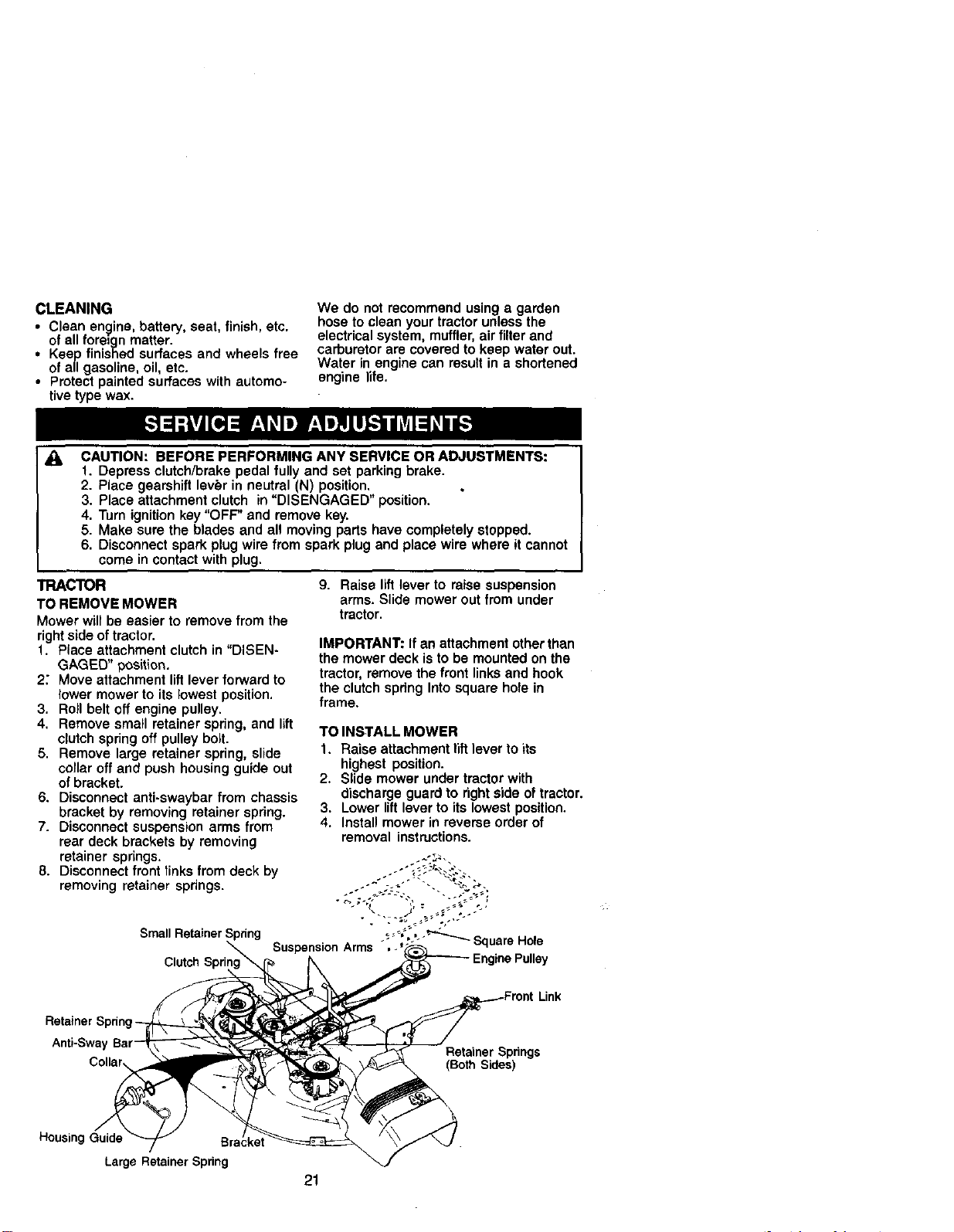
TRACTOR
TO REMOVE MOWER
Mower will be easier to remove from the
rightside of tractor.
f. Place attachment clutch in "DISEN-
GAGED" position.
2" Move attachment lift lever forward to
lower mower to its lowest position.
3. Roll belt off engine pulley.
4. Remove small retainer spring, and lift
clutch spring off pulley bolt.
5. Remove large retainer spring, slide
collar off and push housing guide out
of bracket.
6. Disconnect anti-swaybar from chassis
bracket by removing retainer spring.
7. Disconnect suspension arms from
rear deck brackets by removing
retainer springs.
8. Disconnect front links from deck by
removing retainer springs.
Small R
Clutch Spri
9. Raise lift lever to raise suspension
arms. Slide mower out from under
tractor.
IMPORTANT: If an attachment other than
the mower deck is to be mounted on the
tractor, remove the front links and hook
the clutch spring Into square hole in
frame.
TO INSTALL MOWER
1. Raise attachment lift lever to its
highest position.
2. Slide mower under tractor with
discharge guard to right side of tractor.
3. Lower lift lever to its lowest position.
4. Install mower in reverse order of
removal instructions.
SuspensionArms -",._';'-"'_ Square Hole
Link
Anti-Swa,
Retainer Springs
(BothSides)
HousingGuide
LargeRetainerSpring
2!
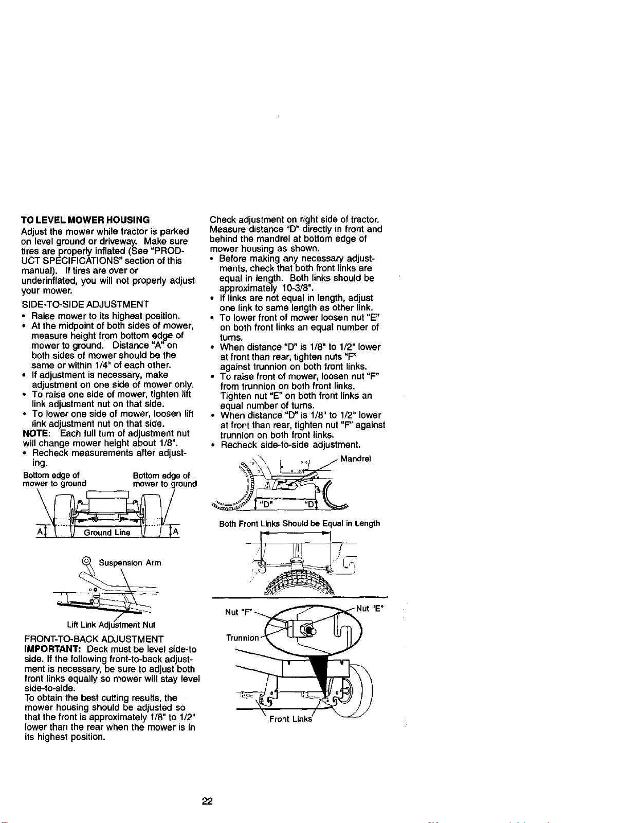
TOLEVELMOWERHOUSING
Adjustthemowerwhiletractorisparked
onlevelgroundorddveway.Makesure
tiresareproperlyinflated(See=PROD-
UCT SPECIFICATIONS" section of this
manual). If tires are over or
underinflated, you will not properly adjust
your mower.
SIDE-TO-SIDE ADJUSTMENT
• Raise mower to its highest position.
• At the midpoint of both sides of mower,
measure height from bottom edge of
mower to ground. Distance "A" on
both sides of mower should be the
same or within 1/4" of each other.
• If adjustment is necessary, make
adjustment on one side of mower only.
• To raise one side of mower, tighten lift
link adjustment nut on that side.
• To lower one side of mower, loosen lift
link adjustment nut on that side.
NOTE: Each full turn of adjustment nut
will change mower height about 1/8".
• Recheck measurements after adjust-
ing.
Bottomedgeof Bottomedgeof
mowerto ground mowerto ground
Check adjustment on right side of tractor.
Measure distance "D" directly in front and
behind the mandrel at bottom edge of
mower housing as shown.
• Before making any necessary adjust-
ments, check that both front links are
equal in length. Both links should be
approximately 10-3/8".
• If links are not equal in length, adjust
one link to same length as other link.
• To lower front of mower loosen nut "E"
on both front links an equal number of
turns.
• When distance "D" is 1/8" to 1/2" lower
at front than rear, tighten nuts "F"
against trunnion on both front links.
• To raise front of mower, loosen nut "F"
from trunnion on both front links.
Tighten nut "E" on both front links an
equal number of turns.
• When distance "D" is 1/8" to 1/2" lower
at front than rear, tighten nut "F" against
trunnion on both front links.
• Recheck side-to-side adjustment.
Both Front Links Should be Equal in Length
FRONT-TO-BACK ADJUSTMENT
IMPORTANT: Deck must be level side-to
side. If the following front-to-back adjust-
ment is necessary, be sure to adjust both
front links equally so mower will stay level
side-to-side.
To obtain the best cutting results, the
mower housing should be adjusted so
that the front is approximately I/8" to 1/2"
lower than the rear when the mower is in
its highest position.
Trunni
22
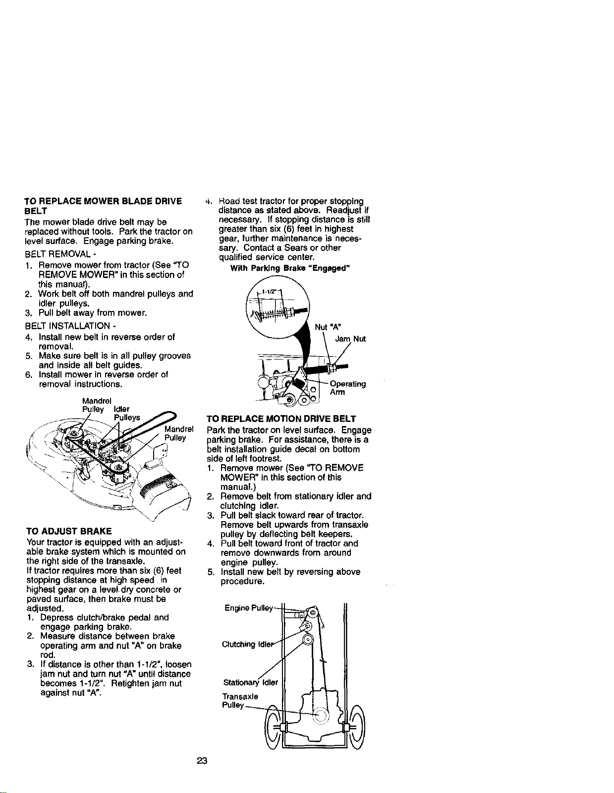
TO REPLACE MOWER BLADE DRIVE
BELT
The mower blade drive belt may be
replaced without tools. Park the tractor on
level surface. Engage parking brake.
BELT REMOVAL -
1. Remove mower from tractor (See "TO
REMOVE MOWER" in this section of
this manual).
2. Work belt off both mandrel pulleys and
idler pulleys.
3. Pull belt away from mower.
BELT INSTALLATION -
4. Install new belt in reverse order of
removal.
5. Make sure belt is in all pulley grooves
and inside all belt guides.
6. Install mower in reverse order of
removal instructions.
Mandrel
Pulley Idler
Pulley
TO ADJUST BRAKE
Your tractor is equipped with an adjust-
able brake system which is mounted on
the right side of the transaxle.
If tractor requires more than six (6) feet
stopping distance at high speed in
highest gear on a level dry concrete or
paved surface, then brake must be
adjusted.
1. Depress clutch/brake pedal and
engage parking brake.
2. Measure distance between brake
operating arm end nut "A"on brake
rod.
3. If distance is other than 1-I/2", loosen
jam nut and turn nut "A" until distance
becomes 1-1/2". Retighten jam nut
against nut "A".
4. Hoad test tractor for proper stopping
distance as stated above. Readjust if
necessary. If stopping distance is still
greater than six (6) feet in highest
gear, further maintenance is neces-
sary. Contact a Sears or other
qualified seP,'ice center.
With Parking Brake "Engaged"
"_ Nut "A"
_ _'_ OPrPmerating
TO REPLACE MOTION DRIVE BELT
Park the tractor on level surface. Engage
parking brake. For assistance, there is a
belt installation guide decal on bottom
side of left footrest.
1. Remove mower (See "TO REMOVE
MOWER" in this section of this
manual.)
2. Remove belt from stationary idler and
clutching idler.
3. Pull belt slack toward rear of tractor.
Remove belt upwards from transaxle
pulley by deflecting belt keepers.
4. Pull belt toward front of tractor and
remove downwards from around
engine pulley.
5. Install new belt by reversing above
procedure.
Clutchin
Transaxle
23
TO ADJUST STEERING WHEEL ALIGN-
MENT
If steedng wheel crossbars are not
horizontal (left to right) when wheels are
positioned straight forward, remove
steering wheel and reassemble per
instructions in the Assembly section of
this manua!.
FRONT WHEEL TOE-IN/CAMBER
The front wheel toe-in and camber are
not adjustable on your tractor. If damage
has occurred to affect the front wheel toe-
in or camber, contact a Sears or other
qualified service center.
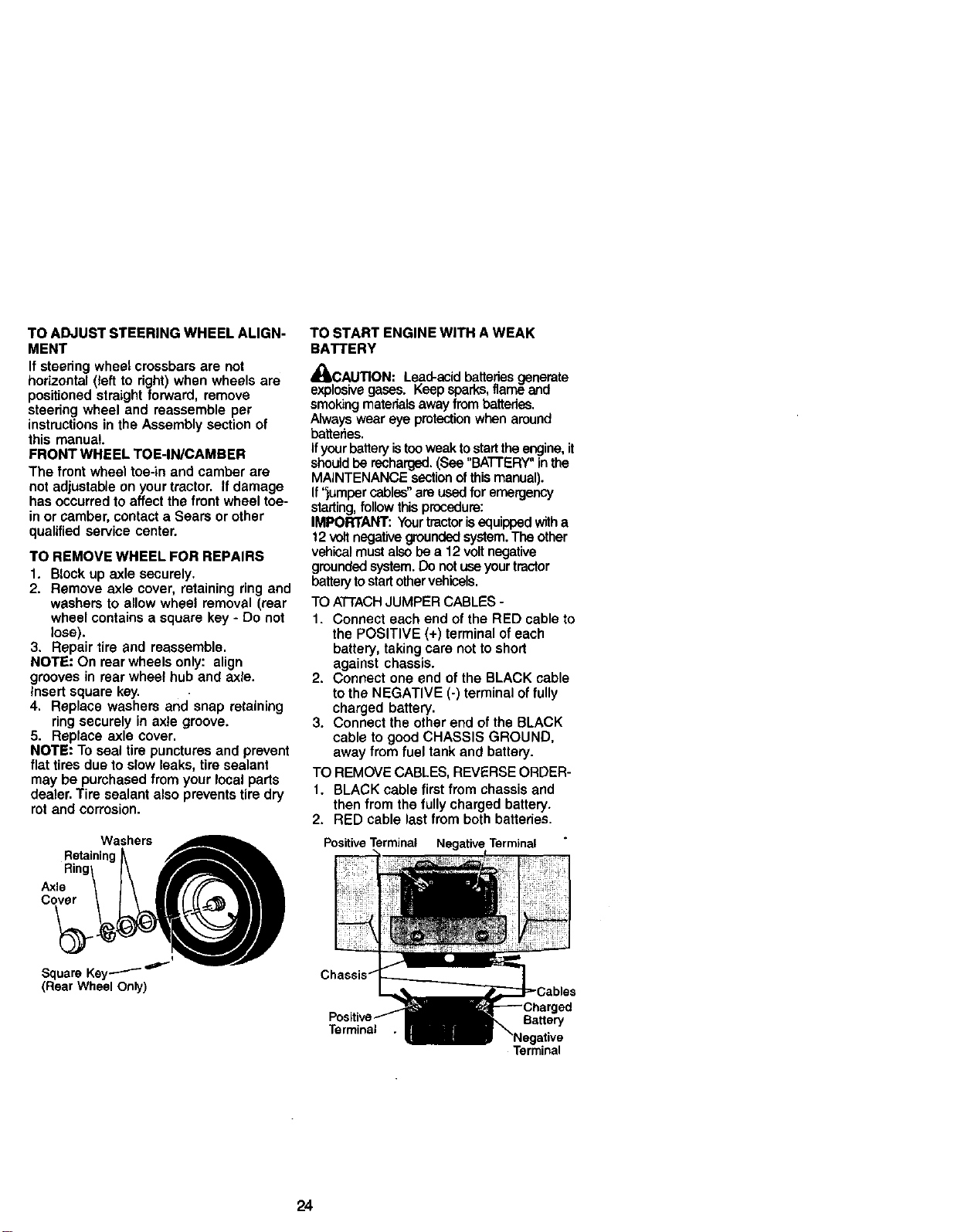
TO REMOVE WHEEL FOR REPAIRS
1. Block up axle securely.
2. Remove axle cover, retaining ring and
washers to allow wheel removal (rear
wheel contains a square key - Do not
lose).
3. Repair tire and reassemble.
NOTE: On rear wheels only: align
grooves in rear wheel hub and axle.
Insert square key.
4. Replace washers and snap retaining
ring securely in axle groove.
5. Replace axle cover.
NOTE: To seal tire punctures and prevent
flat tires due to slow leaks, tire sealant
may be purchased from your local parts
dealer. Tire sealant also prevents tire dry
rot and corrosion.
Washers
Retaining
Axle
Cover
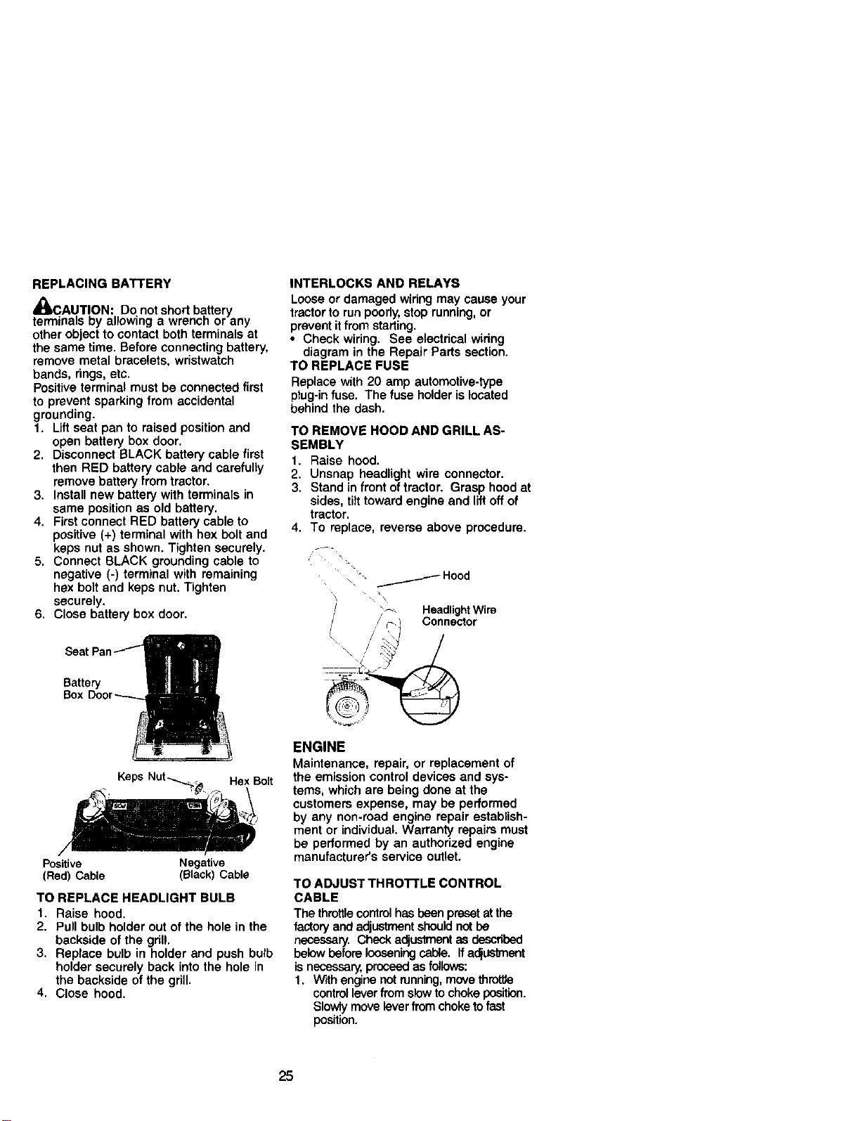
TO START ENGINE WITH A WEAK
BATTERY
.%
4UM3AUTION: Lead-acid batteries generate
explosive gases. Keep sparks,flame and
smoking materialsaway from batteries.
Always wear eye protectionwhen around
batteries.
Ifyour batteryistooweak tostartthe engine,it
shouldbe recharged.(See "BATTERY" inthe
MAINTENANCE sectionofthis manual).
If "jumper cables"are used foremergency
starting,follow this procsdure:
IMPORTANT: Yourtractorisequippedwitha
12 voltnegative groundedsystem.The other
vehical must also be a 12 volt negative
groundedsystem. Do not useyourtractor
batteryto startothervehiceis.
TO ATrACH JUMPER CABLES -
1. Connect each end of the RED cable to
the POSITIVE (+) terminal of each
battery, taking care not to short
against chassis.
2. Connect one end of the BLACK cable
to the NEGATIVE (-) terminal of fully
charged battery.
3. Connect the other end of the SLACK
cable to good CHASSIS GROUND,
away from fuel tank and battery.
TO REMOVE CABLES, REVERSE ORDER-
1. BLACK cable first from chassis and
then from the fully charged battery.
2. RED cable last from both batteries.
Positive Terminal Negative Terminal
I
Square Key---'-"-"
(Rear Wheel Only)
Terminal
BaKery
Terminal
24
REPLACING BATTERY
diJICAU.T!ON:. Do not short battery
terminals Dy allowing a wrencn or any
other object to contact both terminals at
the same time. Before connecting battery,
remove metal bracelets, wristwatch
bands, rings, etc.
Positive terminal must be connected first
to prevent sparking from accidental
grounding.
1. Lift seat pan to raised position and
open battery box door.
2. Disconnect BLACK battery cable first
then RED battery cable and carefully
remove battery from tractor.
3. Install new battery with terminals in
same position as old battery.
4. First connect RED battery cable to
positive (+) terminal with hex bolt and
INTERLOCKS AND RELAYS
Loose or damaged wiring may cause your
tractor to run poorly,stop running, or
prevent itfrom starting.
• Check wiring. See electrical wiring
diagram in the Repair Parts section.
TO REPLACE FUSE
Replace with 20 amp automotive-type
plug-infuse. The fuse holder is located
behind the dash.
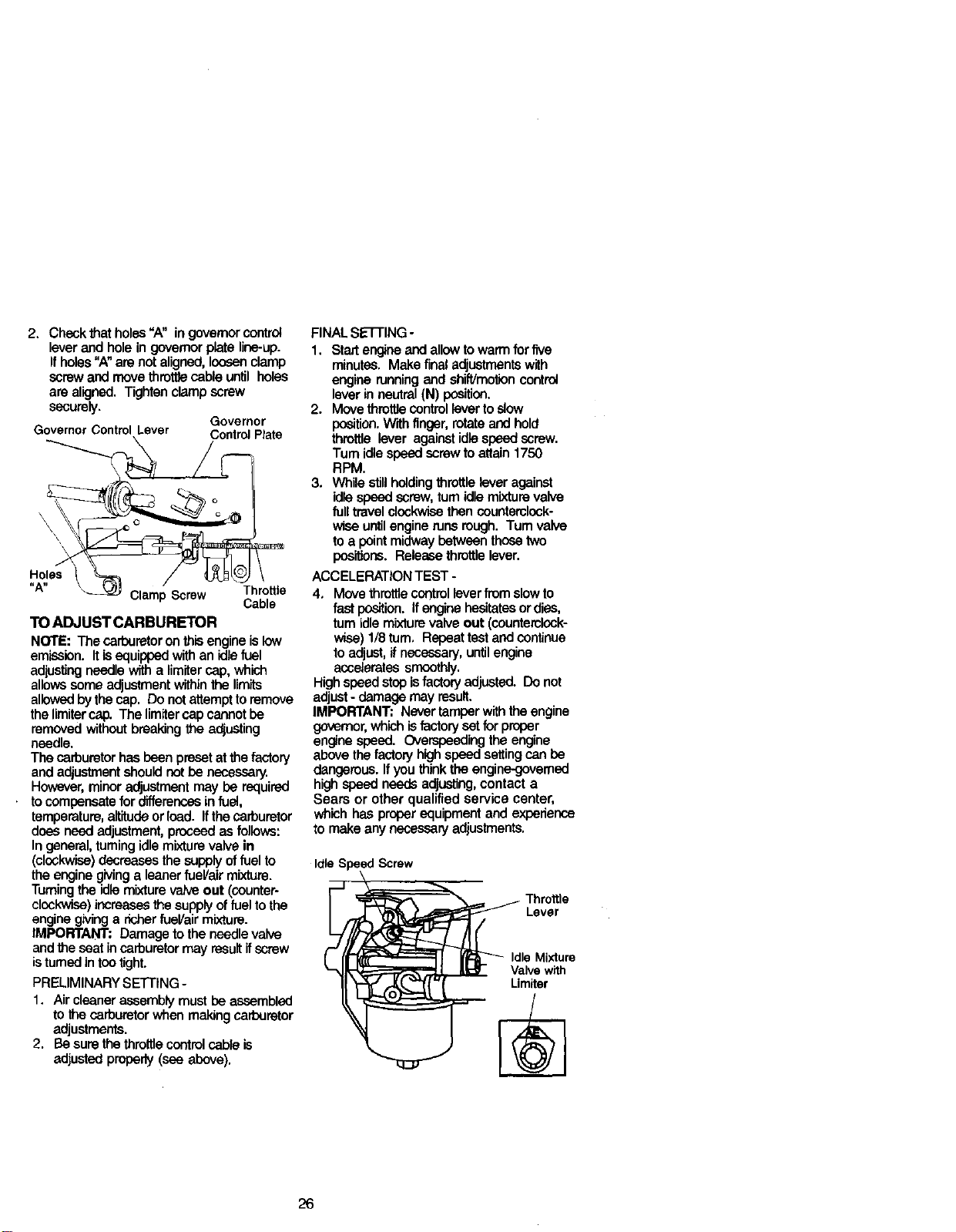
TO REMOVE HOOD AND GRILL AS-
SEMBLY
1. Raise hood.
2, Unsnap headlight wire connector.
3. Stand in front of tractor. Grasp hood at
sides, tilt toward engine and lift off of
tractor.
4. To replace, reverse above procedure.
keps nut as shown. Tighten securely. ---
5. Connect BLACK grounding cable to ' _-
negative (-) terminal with remaining \ -_ _..------Hood
hex bolt and keps nut. Tighten , •
securely. ', _
6. Close battery box door. / :_ HeadlightWire
/ / r-_ Connector
Seat F \. ,/'
Battery "_- _'_ -
Keps Nut_, _ Hex Bolt
Positive Negative
(Red) Cable (Black) Cable
TO REPLACE HEADLIGHT BULB
1. Raise hood.
2. Pull bulb holder out of the hole in the
backside of the grill.
3. Replace bulb in holder and push bulb
holder securely back into the hole in
the backside of the grill.
4. Close hood.
ENGINE
Maintenance, repair, or replacement of
the emission control devices and sys-
tems, which are being done at the
customers expense, may be performed
by any non-road engine repair establish-
ment or individual. Warranty repairs must
be performed by an authorized engine
manufacturer's service outlet.
TO ADJUST THROTTLE CONTROL
CABLE
The throttle controlhas beenpreset at the
factory and adjustmentshould notbe
necessary. Check adjustmentas described
belowbefore looseningcable. If adjustment
is necessary, proceed as follows:
1. W'_thengine not running,movethrottle
controlleverfrom slowto choke position.
Slowly move leverfrom choke tofast
position.
25
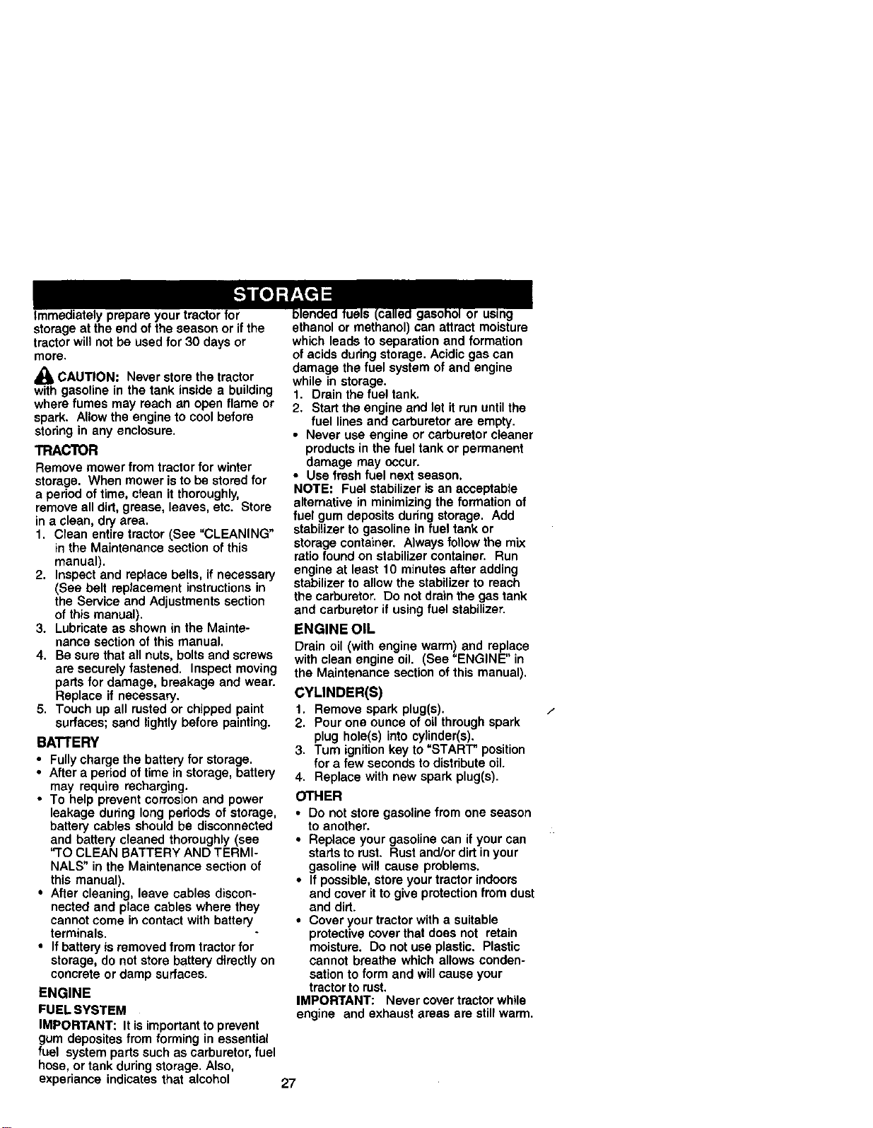
2. Check that holes"A" in governorcontrol
lever and hole in governorplate line-up.
If holes"A"are not aligned, Ion_enclamp
screwand move throttle cable until holes
are aligned. Tighten clamp screw
securely,
Governor
Governor Control Lever ControlPlate
Holes
,=A,I
Clamp Screw Throttle
Cable
TO ADJUST CARBURETOR
NOTE: The carburetoronthis engine islow
emission. Itisequippedwith an idlefuel
adiustingneedle with a limitercap, which
allowssome adjustmentwithinthe limits
allowedby the cap. Do notattempt to remove
the limitercap. The limitercap cannot be
removed without breaking the adjusting
needle.
The carburetorhas been preset at the factory
and adjustmentshould not be necessary.
However,minor adjustmentmay be required
tocompensatefor differencesin fuel,
temperature,altitude or load. Ifthe carburetor
does need adjustment,proceed as follows:
In general,turningidlemixturevalve in
(clockwise)decreases the supplyoffuel to
the engine givinga leanerfueVair mixture.
Turningthe idlemixtureva/veout (counter-
clockwise)increases the supplyoffuel to the
engine givinga richerfueVair mixture.
IMPORTANT: Damage to the needle valve
and the seat incarburetormay result ifscrew
istumed in tootight.
PRELIMINARY SETTING -
1. Air cleaner assemblymust be assembled
to the carburetorwhen making carburetor
adjustments.
2. Be sure the throttle controlcable is
adjusted properly(see above).
FINAL SE'I-FING-
1. Start engineand allowto warm for five
minutes. Make final adjustments with
engine runningand shift/motioncontrol
lever in neutral(N) position.
2. Move throttiecontrollevertoslow
p(_tlon. With finger, rotate and hold
throttla lever againstidlespeed screw.
Turn idlespeed screwto attain 1750
RPM.
3. While stillholdingthrottle leveragainst
idlespeed screw,tum idle mixture valve
full travel clockwisethen counterclock-
wise untilengine runs rough. Turn valve
toa pointmidway between those two
positions. Release throttlelever.
ACCELERATION TEST -
4, Move throttlecontrolleverfrom slowto
fast position. If engine hesitatesor dies,
rum idle mixturevalve out (counterclock-
wise) 1/8 tum, Repeat test and continue
to adjust,if necessary, untilengine
accelerates smoothly.
Highspeed stopisfactory adjusted. Do not
adjust- damage may result.
IMPORTANT: Never tamper withthe engine
governor,which isfactory set for proper
engine speed. Overapeeding the engine
above the factonj highspeed settingcan be
dangerous. If youthinkthe engine-governed
high speed needs adjusting,contact a
Sears or other qualified service center,
which has properequipment and experience
to make any necessary adjustments.
Idle Speed Screw
Lever
Idle Mixture
Valvewith
Limiter
26
51_fid_lffuels (ca31_gasohol or using
prepare your tractor for
storage at the end of the season or if the
tractor will not be used for 30 days or
more.
_1, CAUTION: Never store the tractor
with gasoline in the tank inside a building
where fumes may reach an open flame or
spark. Allow the engine to cool before
storing in any enclosure.
TRACTOR
Remove mower from tractor for winter
storage. When mower is to be stored for
a period of time, clean it thoroughly,
remove all dirt, grease, leaves, etc. Store
in a clean, dry area.
1. Clean entire tractor (See "CLEANING"
in the Maintenance section of this
manual).
2. Inspect and replace belts, if necessary
(See belt replacement instructions in
the Service and Adjustments section
of this manual).
3. Lubricate as shown in the Mainte-
nance section of this manual.
4. Be sure that all nuts, bolts and screws
are securely fastened. Inspect moving
parts for damage, breakage and wear.
Replace if necessary.
5. Touch up all rusted or chipped paint
surfaces; sand lightly before painting.
BATTERY
• Fully charge the battery for storage.
• After a period of time in storage, battery
may require recharging.
• To help prevent corrosion and power
leakage during long periods of storage,
battery cables should be disconnected
and battery cleaned thoroughly (see
"TO CLEAN BATTERY AND TERMI-
NALS" in the Maintenance section of
this manual).
• After cleaning, leave cables discon-
nected and place cables where they
cannot come in contact with battery
terminals.
• If battery is removed from tractor for
storage, do not store battery directly on
concrete or damp surfaces.
ENGINE
FUEL SYSTEM
IMPORTANT: It is important to prevent
gum deposites from forming in essential
fuel system parts such as carburetor, fuel
hose, or tank during storage. Also,
experiance indicates that alcohol
or using
ethanol or methanol) can attract moisture
which leads to separation and formation
of acids during storage. Acidic gas can
damage the fuel system of and engine
while in storage.
1. Drain the fuel tank.
2. Start the engine and let it run until the
fuel lines and carburetor are empty.
• Never use engine or carburetor cleaner
products in the fuel tank or permanent
damage may occur.
• Use fresh fuel next season.
NOTE: Fuel stabilizer is an acceptable
alternative in minimizing the formation of
fuel gum deposits during storage. Add
stabilizer to gasoline in fuel tank or
storage container. Always follow the mix
ratio found on stabilizer container. Run
engine at least 10 minutes after adding
stabilizer to allow the stabilizer to reach
the carburetor. Do not drain the gas tank
and carburetor if using fuel stabilizer.
ENGINE OIL
Drain oil (with engine warm) and replace
with clean engine oil. (See "ENGINE" in
the Maintenance section of this manual).
CYLINDER(S)
t. Remove spark plug(s).
2. Pour one ounce of oil through spark
plug hole(s) into cylinder(s).
3. Tum ignition key to "START" position
for a few seconds to distribute oi1.
4. Replace with new spark plug(s).
OTHER
• Do not store gasoline from one season
to another.
• Replace your gasoline can if your can
starts to rust. Rust and/or dirt in your
gasoline will cause problems.
• If possible, store your tractor indoors
and cover it to give protection from dust
and dirt.
• Cover your tractor with a suitable
protective cover that does not retain
moisture. Do not use plastic. Plastic
cannot breathe which allows conden-
sation to form and will cause your
tractor to rust.
IMPORTANT: Never cover tractor while
engine and exhaust areas are still warm.
/
27
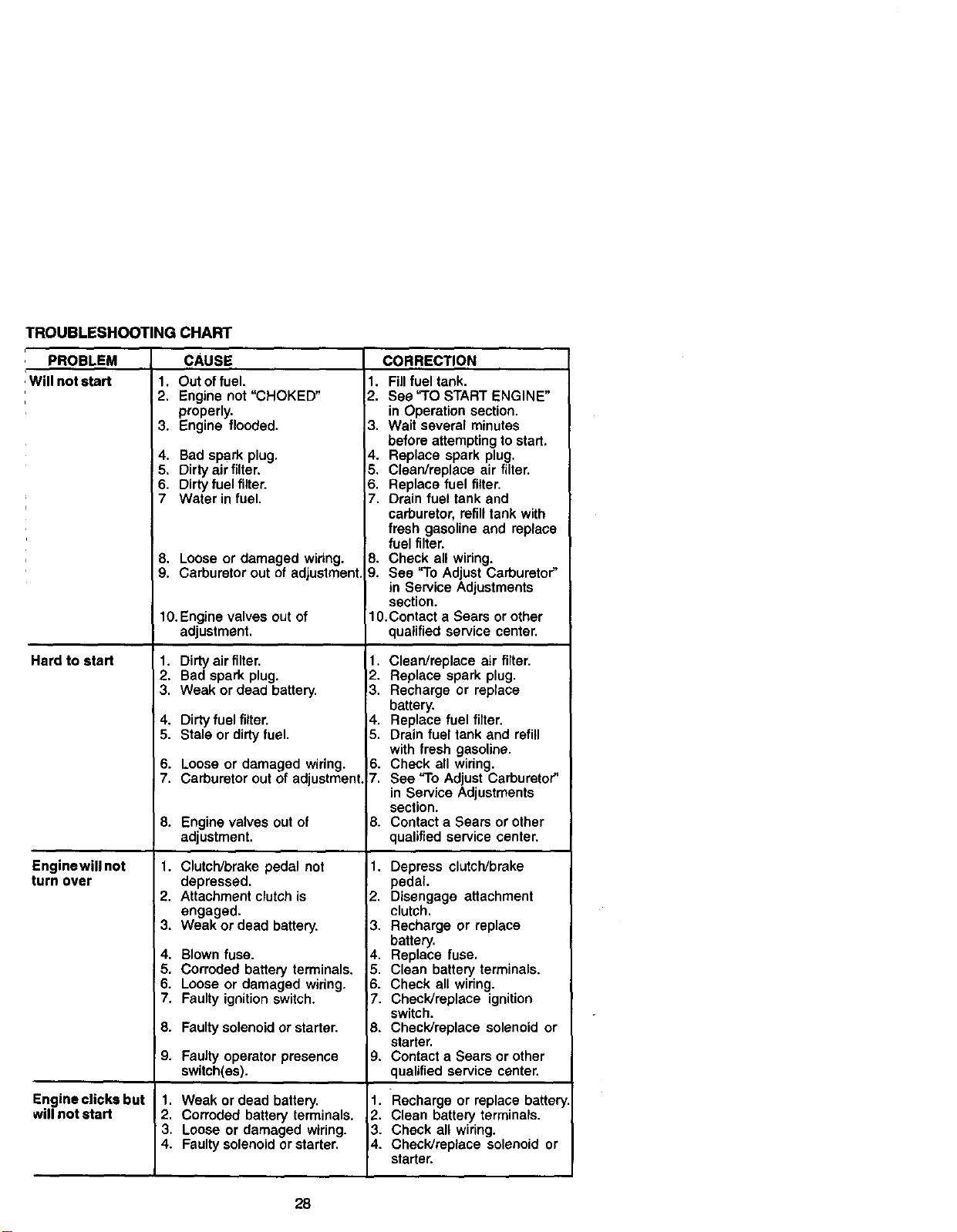
TROUBLESHOOTINGCHART
PROBLEM CAUSE
1
_/ill not start
Hard to start
Enginewill not
turn over
Engineclicks but
willnot start
1. Out of fuel.
2. Engine not "CHOKED"
properly.
3. Engine flooded.
4. Bad spark plug,
5. Dirty air filter.
6. Dirty fuel filter.
7 Water in fuel.
8. Looseor damaged wiring,
9. Carburetorout of adjustment
10.Enginevalvesoutof
adjustment.
1. Dirty air filter.
2. Bad spark plug.
3. Weak or dead battery.
4. Dirty fuel filter.
5. Stale or dirty fuel.
6. Looseor damaged wiring.
7. Carburetor outof adjustment.
8. Enginevalvesoutof
adjustment.
1. Clutch/brake pedal not
depressed.
2. Attachment clutch is
engaged.
3. Weak or dead battery.
4. Blown fuse.
5. Corroded battery terminals.
6. Loose or damaged wiring.
7. Faulty ignition switch.
8. Faulty solenoid or starter.
9. Faulty operator presence
switch(es).
1. Weak or dead battery.
2. Corroded battery terminals.
3. Loose or damaged wiring.
4. Faulty solenoid or starter.
CORRECTION
1. Fillfuel tank.
,2 See "TO START ENGINE"
in Operation section.
3. Wait several minutes
before attempting to start,
4. Replace spark plug.
5. Clean/replace air filter.
8. Replace fuel filter.
7. Drain fuel tank and
carburetor, refill tank with
fresh gasoline and replace
fuel filter.
8. Check all widng.
9. See "To Adjust Carburetor"
in Service Adjustments
section.
1O.Contact a Sears or other
qualified service center.
1. Clean/replace air filter.
2. Replace spark plug.
3. Recharge or replace
battery.
4. Replace fuel filter.
5. Drain fuel tank and refill
with fresh gasoline.
6. Check all widng.
7. See "To Adjust Carburetor"
in Service Adjustments
section.
8. Contact a Sears or other
qualified service center,
1. Depress clutch/brake
pedal.
2. Disengage attachment
clutch.
3. Recharge or replace
battery.
4. Replace fuse.
5. Clean battery terminals.
6. Check all wiring.
7. Check/replace ignition
switch.
8. Check/replace solenoid or
starter.
9. Contact a Sears or other
qualified service center.
1. Recharge or replace batter
2. Clean battery terminals.
3. Check all wiring.
4. Check/replace solenoid or
starter.
28
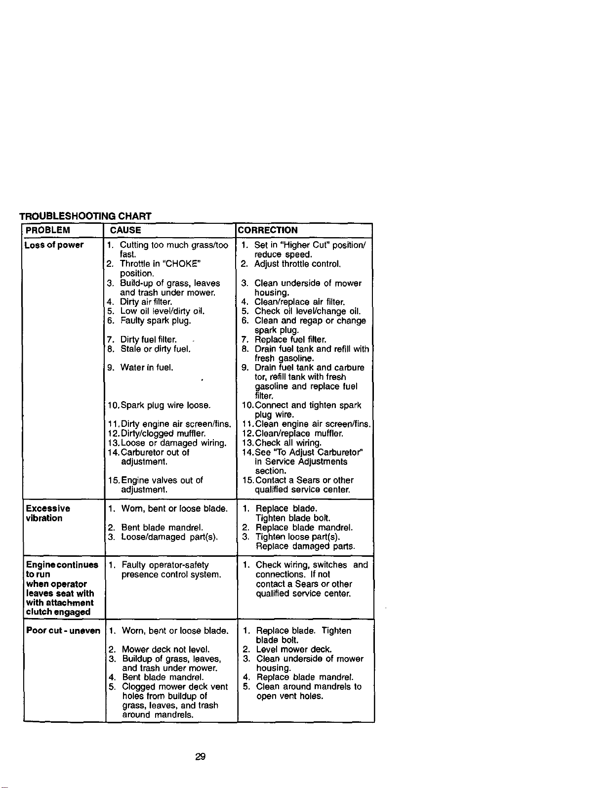
TROUBLESHOOTING CHART
PROBLEM CAUSE
Loss of power 1. Cutting too much grass/too
fast.
2. Throttle in "CHOKE"
position.
3. Build-up of grass, leaves 3.
and trash under mower.
4. Dirty air filter. 4.
5. Low oil level/dirty oil. 5.
6. Faulty spark plug. 6.
7. Dirty fuel filter. , 7.
8. Stale or dirty fuel. 8.
9. Water in fuel. 9.
10,Spark plug wire loose.
Excessive
vibration
Enginecontinues
to run
when operator
leaves seat with
with attachment
clutch engaged
Poorcut-uneven
11,Dirty engine air screen/fins.
12. Dirty/clogged muffler.
13.Loose or damaged wiring.
14.Carburetor out of
adjustment.
15. Engine valves out of
adjustment.
1. Worn, bent or loose blade.
12. Bent blade mandrel.
3. Loose/damaged part(s).
1. Faulty operator-safety
presence control system.
t. Worn, bent or loose blade.
2. Mower deck not level.
3. Buildup of grass, leaves,
and trash under mower.
4. Bent blade mandrel.
5. Clogged mower deck vent
holes from buildup of
grass, leaves, and trash
around mandrels.
CORRECTION
1. Set in "Higher Cut" position/
reduce speed.
2. Adjust throttle control.
Clean undersideof mower
housing.
Clean/replace air filter.
Check oil level/change oil.
Clean and regap or change
spark plug.
Replace fuel filter.
Drain fuel tank and refill with
fresh gasoline.
Drain fuel tank and carbure
tor, refill tank with fresh
gasoline and replace fuel
filter,
10.Connect and tighten spark
plug wire.
t t.Clean engine air screen/fins,
12.ClearVreplace muffler.
13.Check all wiring.
14. See "To Adjust Carburetor"
in Service Adjustments
section.
15.Contact a Sears or other
qualified service center.
1. Replace blade.
Tighten blade bolt.
2. Replace blade mandrel.
3. Tighten loose part(s).
Replace damaged parts.
1. Check wiring, switches and
connections. If not
contact a Sears or other
qualified service center.
1. Replace blade. Tighten
blade bolt.
2. Level mower deck.
3. Clean underside of mower
housing.
4. Replace blade mandrel.
5. Clean around mandrels to
open vent holes.
29

TROUBLESHOOTING CHART
PROBLEM
_lower blades will
not rotate
Poor grass
discharge
Headlight(s) not
working
(ifso equipped)
CAUSE
1. Obstructioninclutch
mechanism.
2. Worn/damaged mower
ddve belt.
3. Frozenidler pulley.
4. Frozenblade mandrel.
1. Engine speed too slow.
2. Travelspeed too fast.
3. Wet grass.
4. Mower decknot level.
5. Low/uneventire air
pressure.
6. Worn,bentor loose blade.
7. Buildup of grass, leaves
and trash under mower.
8. Mower drive belt worn.
9. Blades improperly installed.
10. Improper blades used.
11.Cloggedmower deck vent
holesfrom buildup of grass,
leaves, and trash around
mandrels.
1. Switch is "OFF".
2. Bulb(s) burned out.
3. Faulty light switch.
4. Loose or damaged wiring.
5. Blown fuse.
Battery will not 1.
charge 2.
3.
4.
Engine "backfires" 1.
whenturning
',engine"OFF"
Bad battery cell(s).
Poor cable connections.
Faulty regulator
(if so equipped).
Faultyalternator.
Engine throttle control not
set at "SLOW" position
for 30 seconds before
stopping engine.
CORRECTION
1. Remove obstruction.
2. Replace mower drive belt.
i 3. Replace idler pulley.
4. Replace blade mandrel.
1. Place throttle control in
"FAST" position.
2. Shift to slower speed.
3. Allow grass to dry before
mowing.
4. Level mower deck.
5. Check tires for proper air
pressure.
6. Replace/sharpen blade.
Tighten blade bolt.
7. Clean underside of mower
housing.
8. Replace mower drive belt.
9. Reinstall blades sharp edge
down.
10.Replace with blades listed
in this manual.
11.Clean around mandrels to
open vent holes.
1. Turn switch "ON",
2. Replace bulb(s).
3. Check/replace light switch.
4. Check widng and connec
tions.
5. Replace fuse.
1. Replace battery.
2. Check/clean all connec
tions.
3. Replace regulator.
4. Replace alternator.
1. Move throttle control to
"SLOW" position and allow
to idle for 30 seconds before
stopping engine.
3O
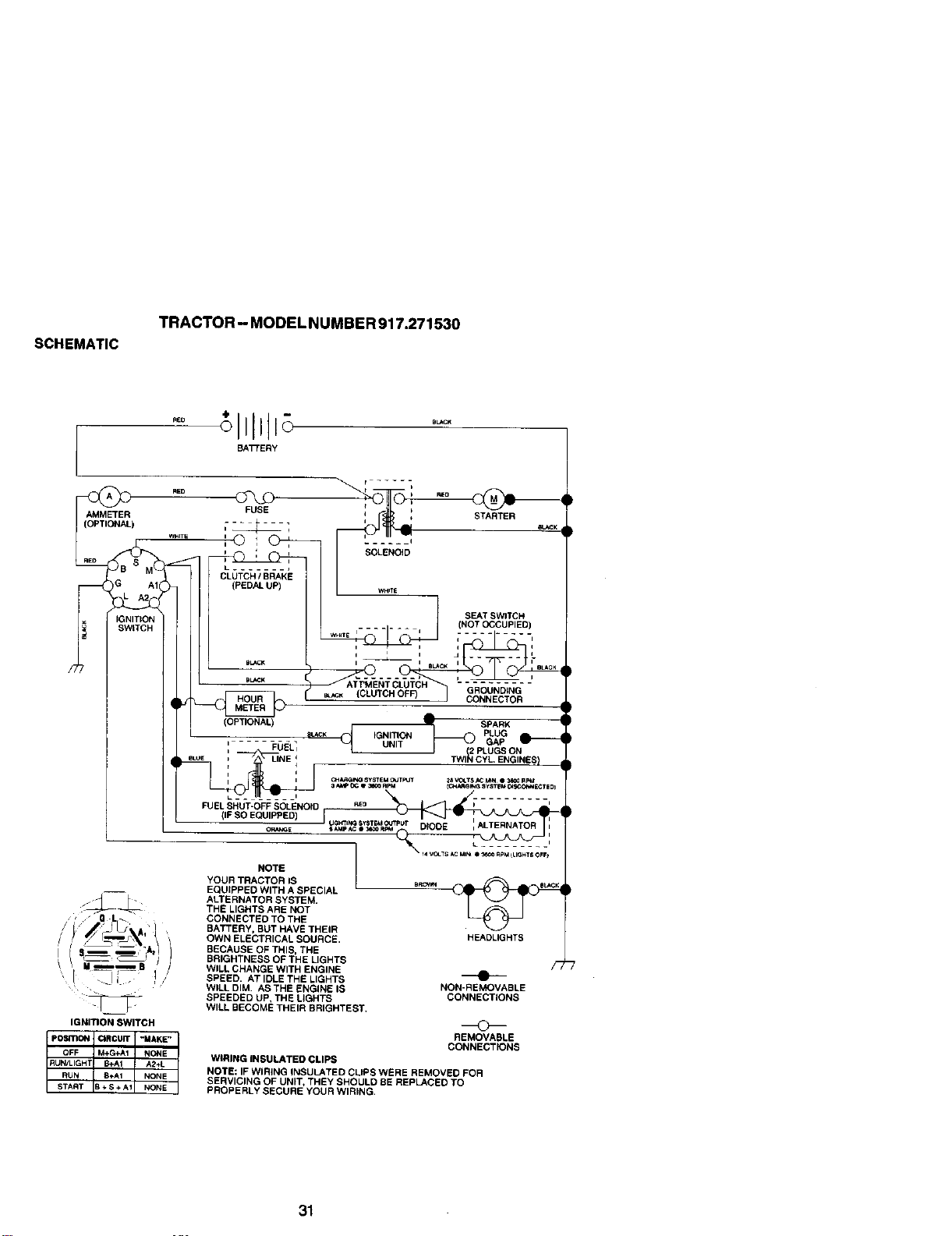
SCHEMATIC
TRACTOR - MODEL NUMBER 917.271530
BATTERY
AMMETER FUSE ', I ST._'_"TER
(OPTIONAL) - _- I _
..... :© : G-_---7 I : .....
i : i SOLENOID
_G AI_ CLUTCH/BRAKE
IGNITION ....... (NOT OCCUPIED
W_ITE I J i- -_-I- _ .-........ i
IGNITION SWITCH
pOSITION CIRCUIT "MAKE"
OFF M+G+AI NONE
START B ÷ S +AI NONE
RUN/LIGHT B+A1 A2÷L
RUN 8÷A1 NONE
(OPTIONAL) -_ SPARK ;
;_ PLUG
SL,_CK IGNITION _ GAP
' _Ij_L_ UNIT
J 12 PLUGS ON
eLUE _r LINE d TWI_ CYL ENGINES
i J
i I cH_ SYSTEMC*JT_JT _6V_TS_,C.._'_II _ Rp_
3_ _X; Q _0 RPM {_ARGff*_ _yST_M _*ONNECTE Di
FUEL SHUT-OFF SOLENOID sso ;" ......
s_p_ e_ooR_ DIODE _ i
NOTE
YOUR TRACTOR IS .P.C_ _ _ _.,_
EQUIPPED WITH A SPECIAL
ALTERNATOR SYSTEM.
THE LIGHTS ABE NOT
CONNECTED TO THE
BATTERY, BUT HAVE THEIR
OWN ELECTRICAL SOURCE. HEADLIGHTS
BECAUSE OF THIS, THE
BRIGHTNESS OF THE LIGHTS
WILL CHANGE WITH ENGINE _'
SPEED. AT IDLE THE LIGHTS
WILL DIM, AS THE ENGINE IS NON-REMOVABLE
SPEEDED UP. THE LIGHTS CONNECTIONS
WILL BECOME THEIR BRIGHTEST.
©
REMOVABLE
CONNECTIONS
WIRING INSULATED CLIPS
NOTE: IF WIRING INSULATED CUPS WERE REMOVED FOR
SERVICING OF UNIT, THEY SHOULD BE REPLACED TO
PROPERLY SECURE YOUR WIRING,
31
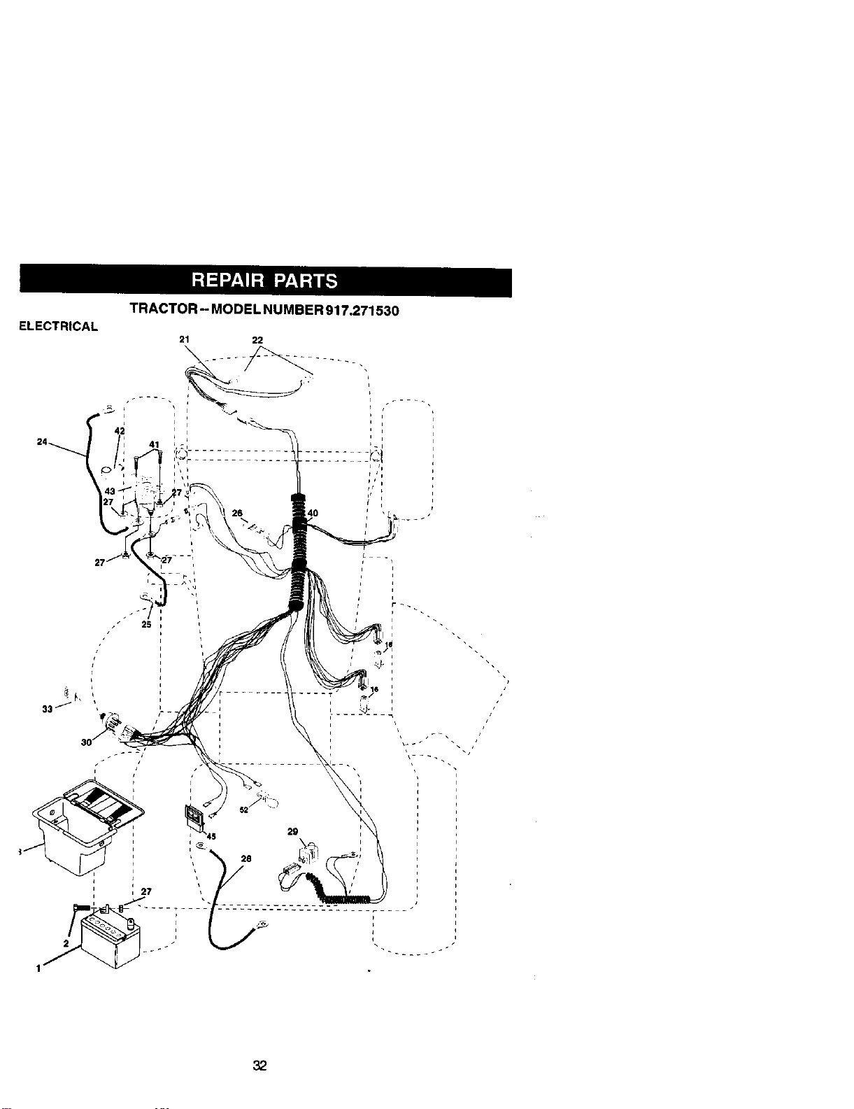
ELECTRICAL
TRACTOR - MODEL NUMBER 917.271530
i I
n
n
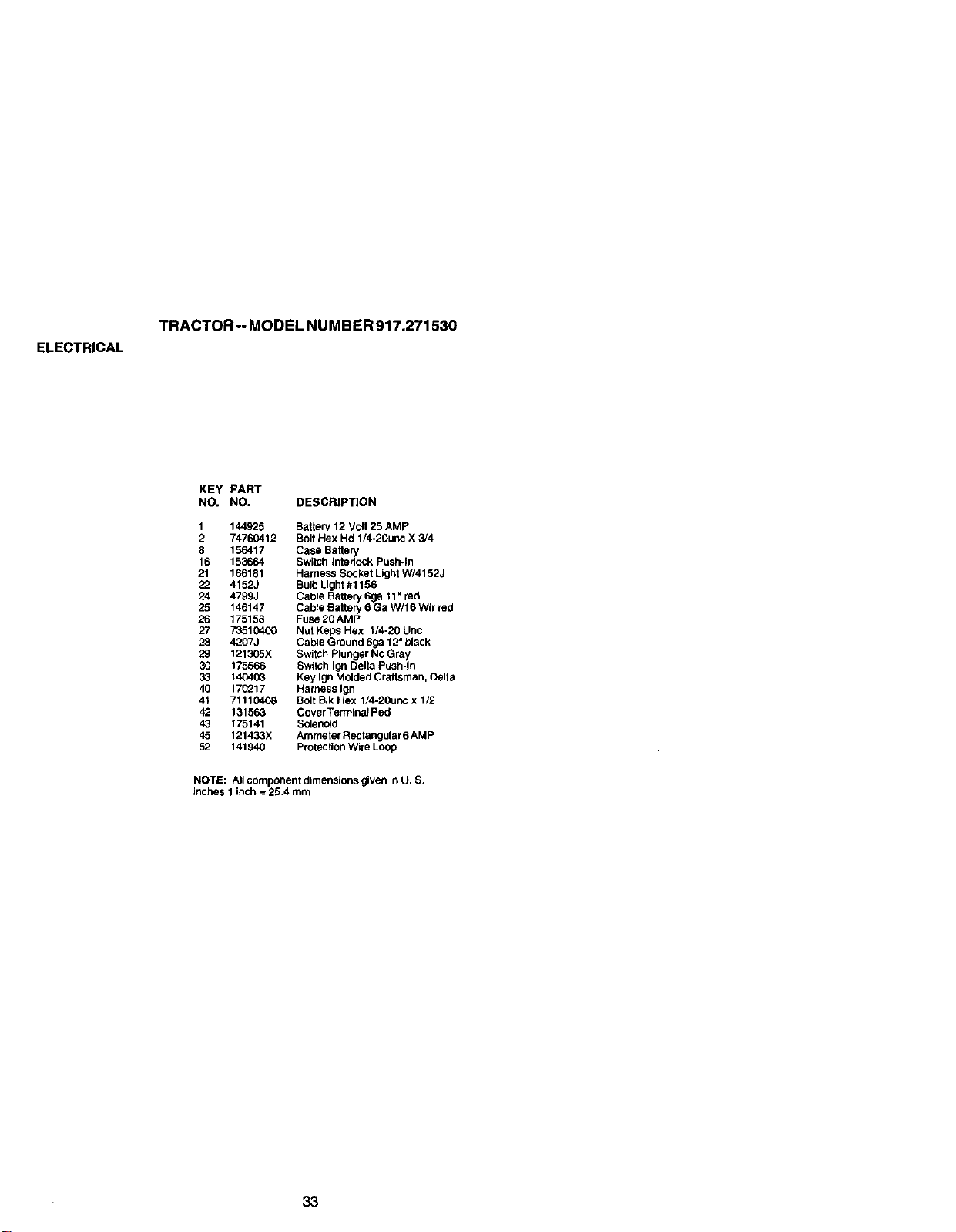
ELECTRICAL
TRACTOR -- MODEL NUMBER 917.271530
KEY PART
NO. NO. DESCRIP_ON
1 144B25 Battery 12 Volt 25 AMP
2 74760412 Bolt Hex Hd 1/4-20unc X 3/4
8 156417 Case Battery
16 153664 Switch _ntedock Push-in
21 166181 Harness Socket Light W/4152J
22 4152J Bulb Light #1156
24 4799J Cable Battery 6ga 11 • red
25 146147 Cable Battery 6 Ga W/I 6 WIr red
26 175158 Fuse 20AMP
27 73510400 Nut Keps Hex 1/4-20 Unc
28 4207J Cable Ground 6ga 12• black
29 121305X Switch Plunger Nc Gray
30 175566 Switch Ig_ Delta Push-in
33 140403 Key Ign Molded Craftsman, Delta
40 170217 Hamess Ign
41 71110408 Bolt BIk Hex 1/4-20unc x 1/2
42 131563 Cover TerminolRed
43 175141 Solenoid
45 121433X Ammeter Rectangular 6 AMP
52 141940 Protection Wire Loop
NOTE: All component dimensions given in U. S.
inches 1 inch = 25,4 mm
33

TRACTOR - MODEL NUMBER 917.271530
CHASSIS AND ENCLOSURES
3O
29
28
54
3O
33
10
35
34
o_ _
2O8
34
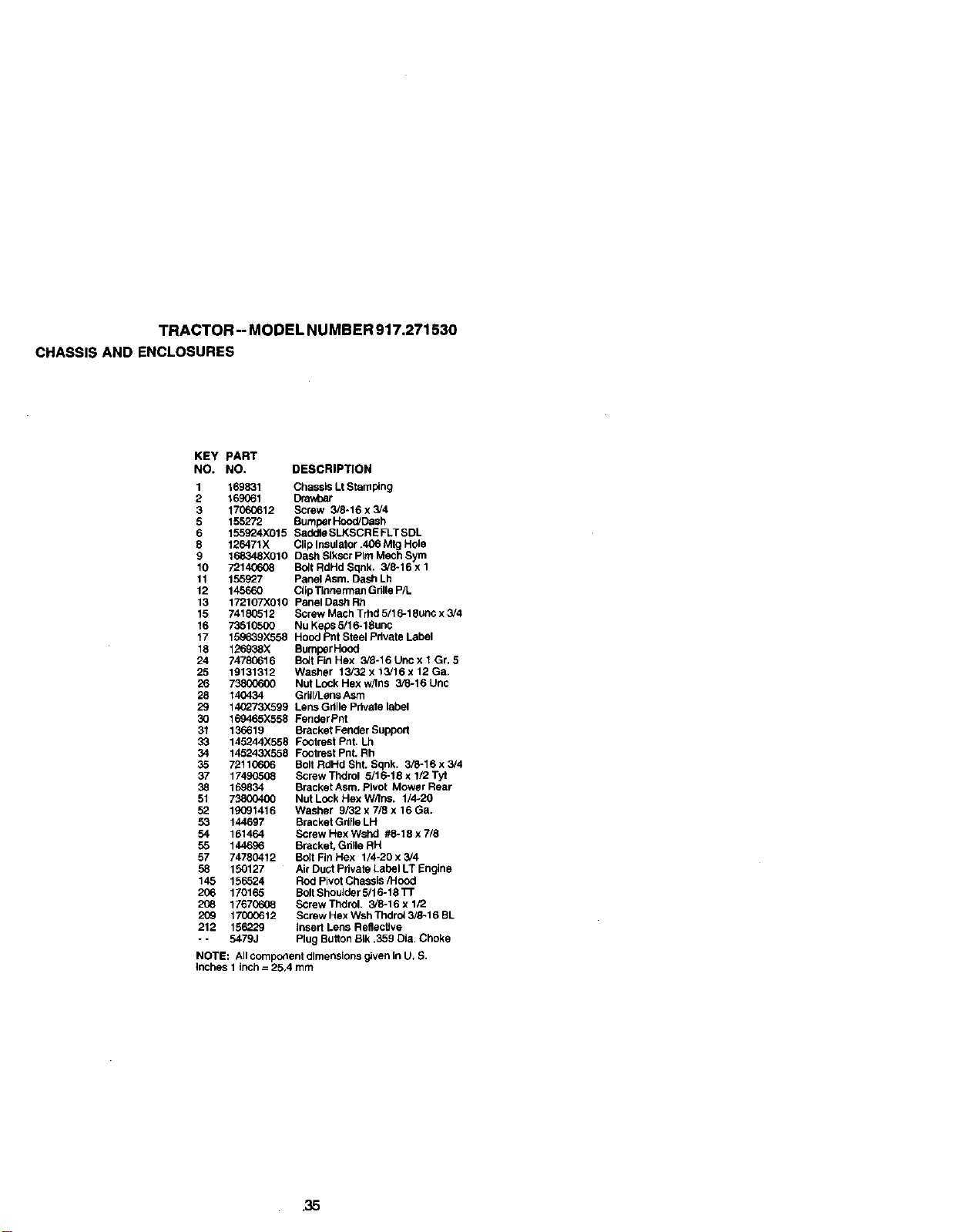
TRACTOR-MODELNUMBER917.271530
CHASSISANDENCLOSURES
KEY PART
NO. NO. DESCRIPTION
1 169831 Chassis Lt Stamping
2 169661
3 17060612 Screw 3/8-16 x 3/4
5 155272 Bumper Hood/Dash
6 155924X015 Soddle SLKSCRE FLT BDL
8 126471X Clip Insulator A06 Mtg Hole
9 168348)(010 Dash Slkscr PIm Mech Sym
10 72140608 Bolt RdHd Sqnk. 3/8-16 x 1
11 155927 Panel Asm. Dash Lh
12 145660 Ctip Tinnerman Gdlle P/L
13 172107X010 Panel Dash Rh
15 74180512 ScrewMachTrhd5/16-18uncx3!4
16 73510500 Nu Keps 5/16-18unc
17 159639X558 Hood Pnt Steel Pdvate Label
18 126938X Bumper Hood
24 74780616 Bdt Fin Hex 3_-16 Unc x 1Gr. 5
25 19131312 Washer 13/32 x 13/16 x 12 Ga.
26 73800600 Nut LoCk Hex w/Ins 3/3-16 Uric
28 140434 Griti/Lens Asm
29 140273X599 Lens Grille Private label
30 169465X558 Fender Pnt
31 136619 Bracket Fender Support
33 145244X558 Footrest Pnt. Lh
34 145243X558 Footrest Pnt. Rb
35 72110606 Bolt RdHd Sht. Sqnk. 3/8-16 x 3/4
37 17490508 ScrewThdrol 5/16-18 x 1/2 Tyt
38 169834 Bracket Asm. Pivot Mower Rear
51 73800400 Nut LoCk Hex W/Ins. 1/4-20
52 19091416 Washer 9/32 x 7/8 x 16 Ga.
53 144697 Bracket Grtile LH
54 161464 Screw Hex Wshd #8-18 x 7/8
55 1_ Bracket, Gd_le RH
57 74780412 Bolt Fin Hex 1/4-20 x 3/4
58 150127 Air Duol Pdvate Label LT Engine
145 156524 Rod Pivot Chassis/Hood
206 170165 Bolt ShouJder 5/16-18 TF
208 17670608 ScrewThdrol. 3/8-16xl/2
209 17000612 Screw Hex WSh Thdro_3/8-16 BL
212 156229 Insert Lens Reflective
- - 5479J Plug Button BIk .359 Dia, Choke
NOTE: All component dimensions given in U. S.
inches 1 inch = 25.4 mm
35
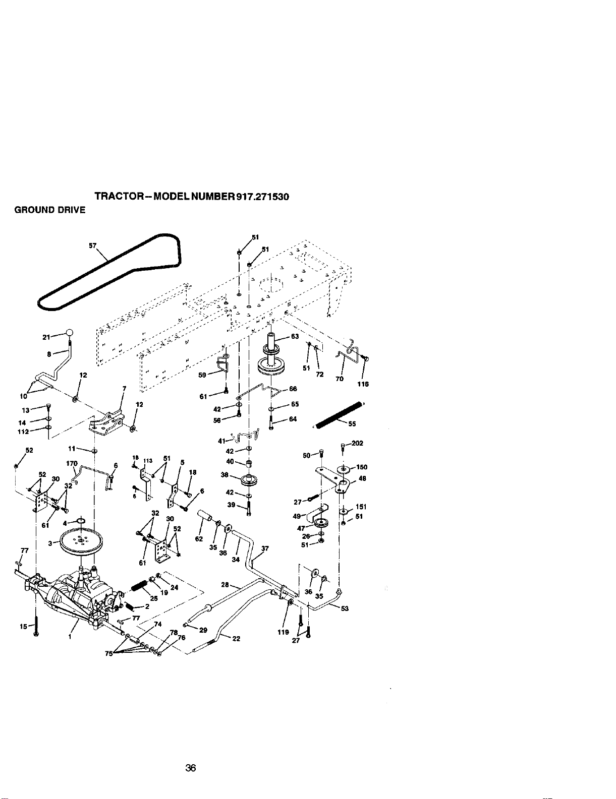
TRACTOR - MODEL NUMBER 917.271530
GROUND DRIVE
77
52
/
17
_113 51 5
18
32
52
119
27
36

TRACTOR-- MODEL NUMBER 917.271530
GROUND DRIVE
KEY PART KEY
NO, NO. DESCRIPTION NO,
1 .... Transaxle (See Breakdown) 42
Dana4360-140 47
2 146682 Spddg Return Brake T/a Zinc 48
3 123666X Pulley Transaxle 18/20" tires 49
4 12000(328 Ring Retainer # 5100-62 50
5 121520X Strap Torgue 30 Degrees 51
6 17060512 Screw 5/16-18 x 3/4 52
7 162240 Bracket Saddle Shift T/a 53
8 131679 Rod Shf Sd_ LY/YT Str Brk Zinc 55
10 STD561210 Pin Cotter 1/9 x I Cad 56
11 195701X Washer Plate Shf 988 Sq Hole 57
12 19151216 Washer 15/32 x 3/4 x 16ga 59
13 74550412 Bolt 1/4-28unf Gr8 W/Patch 61
14 STC551125 Washer Lock Hvy Helical 1/4 62
15 74490544 Bolt Hex FLGHD 5/16-18 Gr.5 63
18 STD523710 Bolt Fin Hex 3/8-16 x 1 64
19 STD541437 Nut Lock Hex W/Ins. 3/8-16 Unc 65
21 106933X Knob Rd 1/2-13 Plstc Thds BIk 66
22 130804 Rod Brake BIk Zinc 26 840 70
24 STD541237 Nut Hex Jam 3/8-16 Unc 72
25 1_o888X Spring Rod Brake 2 00 Zinc 74
26 19131016 Washer 13/32 x 5/8 x 16 Ga 75
27 STD561210 Pin CoRe;"1/8 x 3/4 Cad 76
28 145204 Rod Brake Parking Lt/Yt 77
29 71673 Cap Brake Parking 78
30 174973 Bracket Mtg Transaxle 112
32 STD523107 Bolt Hex Hd 5/16-18unc x 3/4 113
34 155071 Shaft Asm Pedal Foot 116
35 120183X Bearing Nylon BIk 629 Id 150
36 STD551062 Washer 21/32 x 1 x 16 Ga 151
37 STD571810 Pin Roll 3/16 x 1• 170
38 131494 Pulley Idler Flat 202
39 74760644 Bolt Fin Hex 3/8-16 Unc X 2-3/4
40 4470J Specdr Split 395 x 59 Bzp
41 165838 Keeper Belt Idler
PART
NO. DESCRIPTION
19131312 Washer 13/32 x 13/16 x 12 Ga
127783 Pulley Idler V Groove Plastic
154407 Be,crank Clutch Gm Drv Sti
1232_5X Retainer Belt Style Spring
STD523715 Bolt Hex Hd 3/8-16unc x 1-1/2
STD641437 NutCrowntock 3/8-16UNC
STD541431 Nut Crown Lock 5/16-18
1(_710X Link Clutch 7 66
166709X Spring Return Clutch 6 75
STD523712 Bolt Fin Hex 3/8-19 unc x 1-1/4
160855 V-Belt Gd Drive
169691 Keeper Belt Centerspan
1706G612 Screw 3/8-16 x 3/4
8883R Cover Pedal BIk Round
140186 Pulley Eng CI Mesh 38deg LT/YT
71170764 Bolt Hex 7/16-20 x 4 Gr 5
STD551143 Washer Lock Hvy Hlol Spr 7/16
154778 Keeper Belt Engine
134683 Golde BSh Mower Diive RH
19132012 Washer 13/32 x 1-1/4 x 12 Ga
1G9502X Spacer Axle
121749X Washer 25/32 x 1 1/4x 16Ga
STD581075 E-dng #5133-75
123583X
121748X
19091210
127285)(
72110610
165850
19133210
173898
72110612
Key Square 2 O x 1945/1665
Washer 25/32 x 1-5/9 x 16ga
Washer 9/32 x 3/4 x 10 Ga
StrapTorque
Bolt Rdhd Sq Neck 3/8-16 x 1.25
Bushing Bellcrank Grd. Drive
Washer 13/32 x 2 x 10 Ga
Keeper Belt Transaxle Gear
Bolt Carr Sh 3/8o16 x 1ol/2 Gr. 5
NOTE: Ati component dimensions given in U. S.
inches 1 inch = 25.4 mm
37
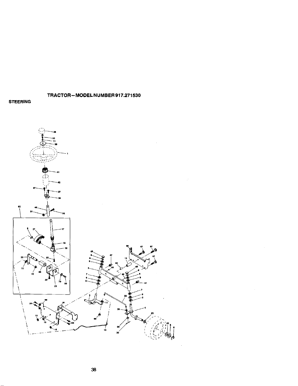
STEERING
TRACTOR - MODEL NUMBER 917.271530
L
.."-:-?_--_'-::f
" @
t isI _
38
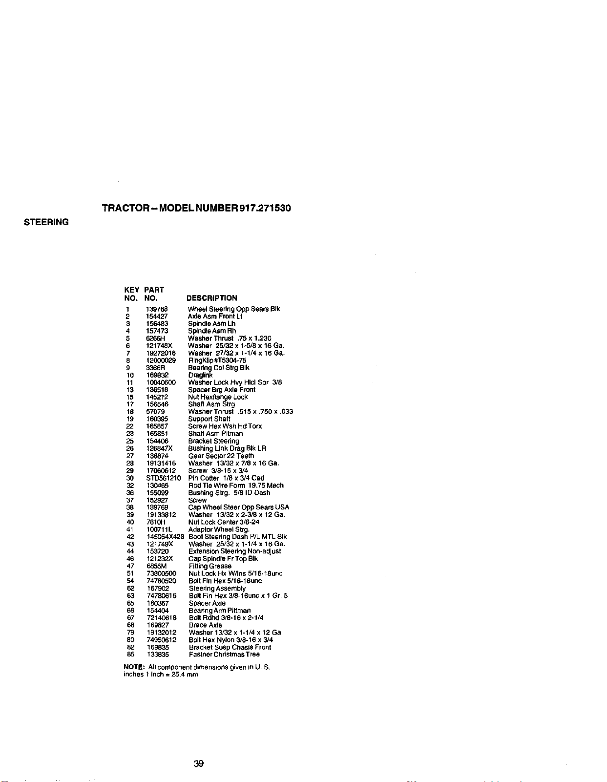
STEERING
TRACTOR - MODEL NUMBER 917.271530
KEY PART
NO. NO. DESCRIPTION
1 139768 Wheel Steering Opp Sears BIk
2 154427 Axle Asm Front Lt
3 156483 Spindle Asm Lh
4 157473 Splnd_e Asm Rh
5 6266H Washer Thrust .75 x 1.230
6 121748X Washer 25/32 x 1_5/8 x 16 Ga.
7 19272016 Washer 27/32 x 1ol/4 x 16 Ga.
8 12000029 RlngFJip#T5304-75
9 3366R Bearing Col Strg BIk
10 169832 Dragllnk
11 10040600 Washer Lock Hvy Hlcl Spr 3/8
13 136515 Spacer Brg Axle Front
15 145212 Nut Hexflange Lock
17 156546 Shaft Asm Strg
18 57079 Washer Thrust .515 x .750 x ,033
19 16_395 Support Shaft
22 165857 Screw Hex Wsh Hd Torx
23 165851 Shall Asm Pitman
25 154406 Bracket Steering
26 126847)( Bushing Link Drag BIk LR
27 136874 Gear Sector 22 Teeth
28 19131416 Washer 13/32 x 7/8 x 16 Ga.
29 17060612 Screw 3/8-16 x 3/4
30 STD5612t0 Pin Cotter I/8 x 3/4 Cad
32 130465 Rod Tte Wire Form 19.75 MeCh
36 155099 Bushing Strg. 5/8 ID Dash
37 152927 Screw
38 t39769 Cap Wheel Steer Opp Sears USA
39 19133812 Washer 13/32 x 2-3/8 x 12 Ga.
40 7810H Nut Lock Center 3/8-24
41 100711L Adaptor Wheel Strg.
42 145054X428 BOOtSteedng Dash P/L MTL BIk
43 121749X Washer 25/32 x 1-1/4 x 16 Ga.
44 153720 Extension Steering Non-adjust
46 121232X Cap Spindte Fr Top BIk
47 6855M Fitting Grease
51 73800500 Nut Lock Hx W/ths 5/16-18uric
54 74780520 Bolt Fin Hex 5/16-18uric
6_ 167902 Steering Assembly
63 74780616 Bolt Fin Hex 3/8-16uric x 1 Gr. 5
65 166B67 Spacer Axle
66 154404 Bearing Arm Pillman
67 72140618 Bolt Rshd 3/8-16 x 2-1/4
68 169827 Brace Axle
79 19132012 Washer 13/32 x 1-1/4 x 12 Ga
80 74950612 Bolt Hex Nylon 3/8-16 x 3/4
82 169835 Bracket Susp Chasis Front
85 133835 Fastner Christmas Tree
NOTE: All component dimensions given in U. S,
inches 1 inch = 25,4 mm
39
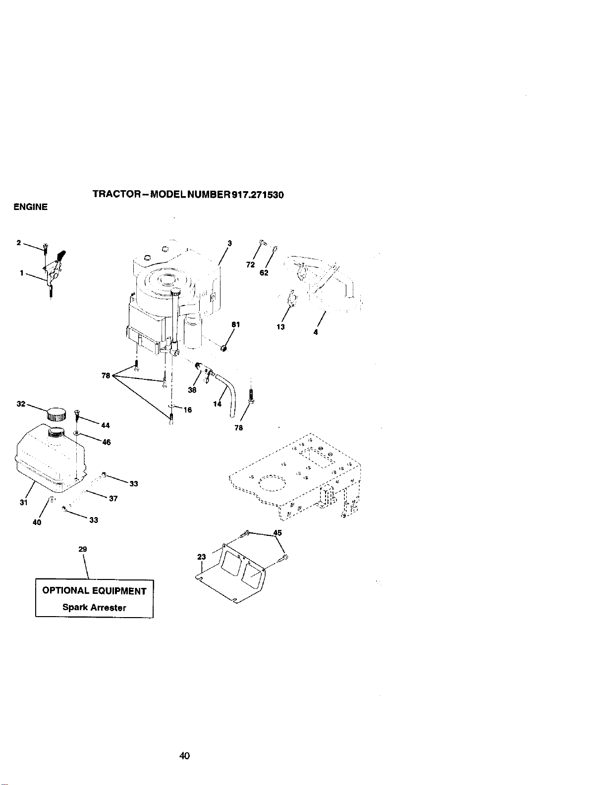
ENGINE
TRACTOR - MODEL NUMBER 917.271530
©
29
OPTIONAL EQUIPMENT
Spark Arrester
3
.I
72
62
13
/
4
14
78
4O
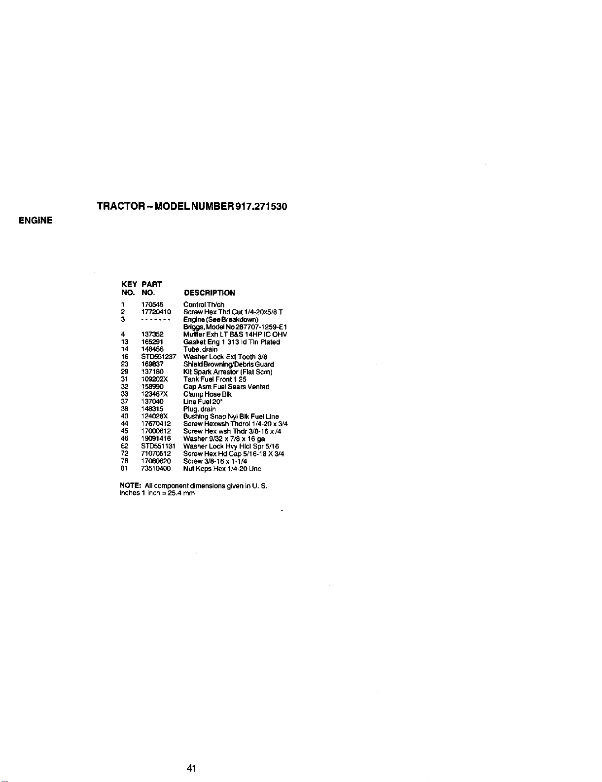
ENGINE
TRACTOR - MODEL NUMBER 917.271530
KEY PART
NO. NO. DESCRIPTION
1 170645 Control TWch
2 17720410 Screw Hex Thd Cut 1/4-20x5/8 T
3 ....... En_ne (See Breakpown)
Bdggs, Model NO287707-1259-E1
4 137352 Muffler Exh LT B&S 14HP IC OHV
13 165291 Gasket Eng 1 313 Id Tin Plated
14 148456 Tube.drain
16 STD551237 Washer Lock Ext Tooth 3/8
23 169837 Shield Browning/Debds Guard
29 137180 Kit Spark Arrestor (Flat Scm)
31 I09202X Tank Fuel Front 1 25
32 158990 Cap Asm Fuel Sears Vented
33 123487X Clamp Hose BIk
37 137040 Line Fuel20"
38 148315 Plug. dreln
40 124028x Bushing Snap Nyl BIk Fuel Line
44 17670412 Screw Hexwsh Thdrol 1/4-20 x 3/4
45 1700C612 Screw Hex wsh Thdr 3/8-16 x/4
46 19G91416 Washer 9/32 x 7/8 x 16 ga
62 STD551131 Washer Lock Hvy Hlcl Spr 5/16
72 71070512 Screw Hex Hd Cap 5/16-18 X 3/4
78 17060620 Screw 3/8-16 x 1-1/4
81 73510400 Nut Keps Hex 1/4-20 Unc
NOTE: All component dimensions given In U. S.
inches 1 inch = 25.4 mm
41
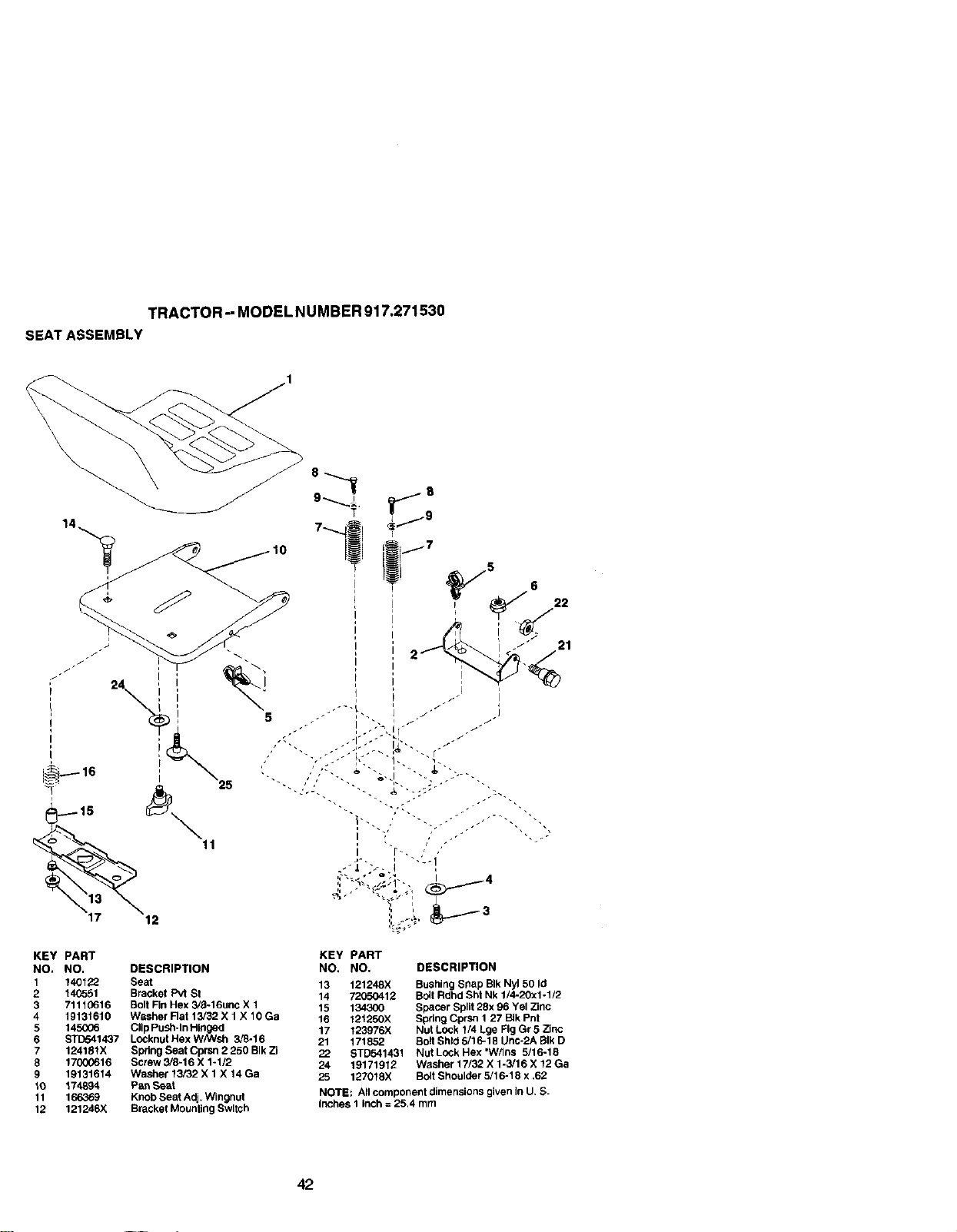
TRACTOR -- MODEL NUMBER 917.271530
SEAT ASSEMBLY
KEY PART KEY PART
NO, NO. DESCRIPTION NO. NO. DESCRIPTION
1 140122 Seat
2 140_551 9r_ck_tPWSt 13 12124BX BusY_S/_ap91klv_50/d
3 71110616 Bolt Fin Hex 3/8-16unc X 1 14 72050412 Boll Rdhd Sht Nk 1/4-20Xl -1/2
t5 t343Q_ Spacer Sptl( 28x 96 Yel Zinc
4 _9131610 Washer Rat 13/32 X 1 X 10 Ga 16 121250X Spring Cprsn I 27 BIk Pnt
5 145006 Clip Push-In Hinged 17 123976X Nut Lock 1/4 Lge Fig Gr 5 Zinc
6 ST[To41437 LOCknutHexW/Wsh 3/8-16
7 124181X Spdr_SeatCprsn2250B_kZi 21 171852 SoltShld5/16-1BUnC.2Ag,_D
22 STD541431 NutLockHex'W/Ins 5/16-18
8 17000616 Screw 3/8=16 X 1-1/2 24 19171912 Washer17/32Xt.3/T6X12Ga
9 19131614 Washer 13/32 X 1 X 14 Ga
10 174894 Pan Se&t 25 127018X Bolt Shoulder 5/16-18 x .62
11 166369 Knob Seat Adj+Wingnut NOTE: All component dimensions given In U, S.
12 121246X Bracket Mounting Switch inshes t inch = 25.4 rnm
42
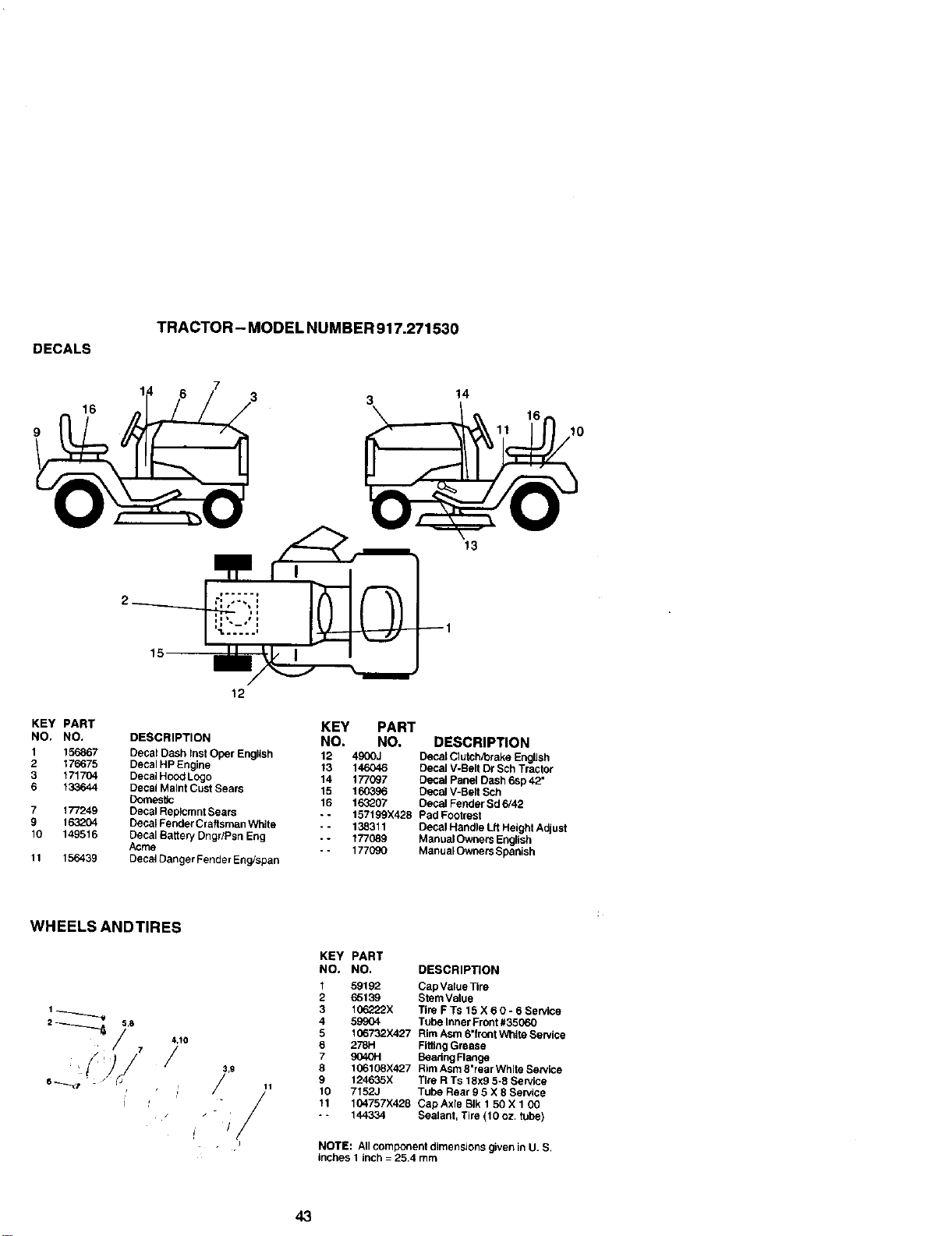
DECALS
TRACTOR - MODEL NUMBER 917.271530
16
3
14
10
13
KEY PART
NO. NO,
1 156867
2 176675
3 171704
6 133644
7 177249
9 193204
10 149516
11 156439
12
DESCRIPTION
Decal Dash lnst Oper English
Decal HP Engine
Decal HO_:_L_:jo
Decal Malnt Cust Sears
Domes_c
Decal Replcmnt Sears
Decal Fender Craftsman White
Decal Baften/Dngr/Psn Eng
Acrne
Decal Danger Fender Eng/span
KEY PART
NO, NO. DESCRIPTION
12 490GJ Decal Clutch,brake English
13 146046 Decal V-Belt Dr Sch Tractor
14 177097 Decal Panel Dash 6sp 42"
15 160396 Decal V-Belt Sch
16 163207 Decal Fender Sd 6/42
-- 157199X428 Pad Footrest
- - 138311 Decal Handle Lft Height Adjust
- - 177089 ManualOwners Engfish
- - 177080 ManualOwners Spaalsh
WHEELS ANDTIRES
3,g
/ -
,I _ -/i/
KEY PART
NO. NO. DESCRIPTION
1 59192 Cap Value Tire
2 65139 StemValue
3 1_o222X Tire F Ts 15 X 6 0 - 6 Service
4 59904 Tube Inner Front #35060
5 1(]6732X427 Rim Asm 6"front Whfte Service
6 278H Fiffing Grease
7 9040H Beadng Flange
8 106108X427 Rim Asm 8"rear White Service
9 124635X Tire R Ts 18x9 5-8 Service
10 7152J Tube Rear 9 5 X 8 Service
11 104757X428 Cap Axle BIk 1 50 X 1 00
- * 144334 Sealant, Tire (10 oz. tube)
NOTE: All component dimensions given in U. S.
inches 1 inch = 25.4 mm
43
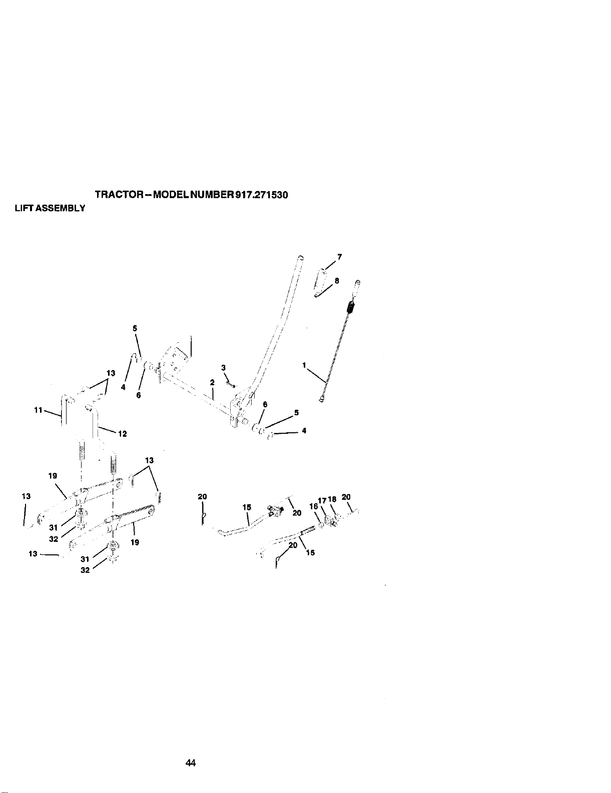
TRACTOR- MODELNUMBER917.271530
LIFTASSEMBLY
19
13
2O
15
44

TRACTOR- MODEL NUMBER 917.271530
LIFT ASSEMBLY
KEY PART
NO. NO. DESCRIPTION
1 159460 Wire Asm Inner/Sprg W/plunger LT
2 159471 Shaft Asm Uft
3 105767X Pin Groove 1 500 Zinc
4 12000002 E Ring #5133-62
5 19211621 Washer PItd 21/32 x 1 X 21ga
6 120183X @eadng Nylon BIk 629 Id
7 125631X Grip Han_e Fluted BIk
8 122365X Button Plunger Red
11 139865 Unk Lift LH
12 139866 Link Lift RH
13 STID624008 Retainer Spdng
15 173288 Link Front
16 73350800 Nut Jam Hex 1/2-13 Unc
17 130171 Trunnion BIk Zinc
18 73800800 Nut Lock W/Wsh 1/2-13unc
19 139868 Arm Suspension Rear
20 163552 Retainer Spring Zinc
31 169865 Bearing I:>vtLift
32 73540600 Nut Crownlcck 3/8-24
NOTE: All component dimensions g_ven In U. S.
inches 1 inch = 25.4 mm
45
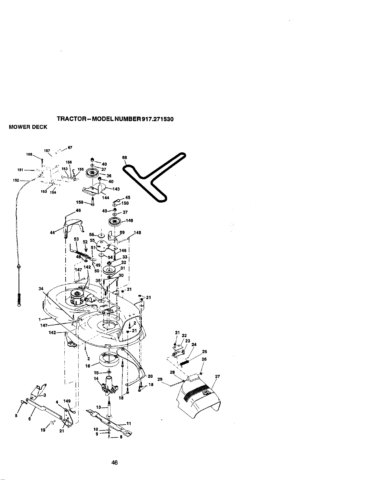
TRACTOR - MODEL NU MBER 917.271530
MOWER DECK
31
34
I
4
19 21
\
16
27
46
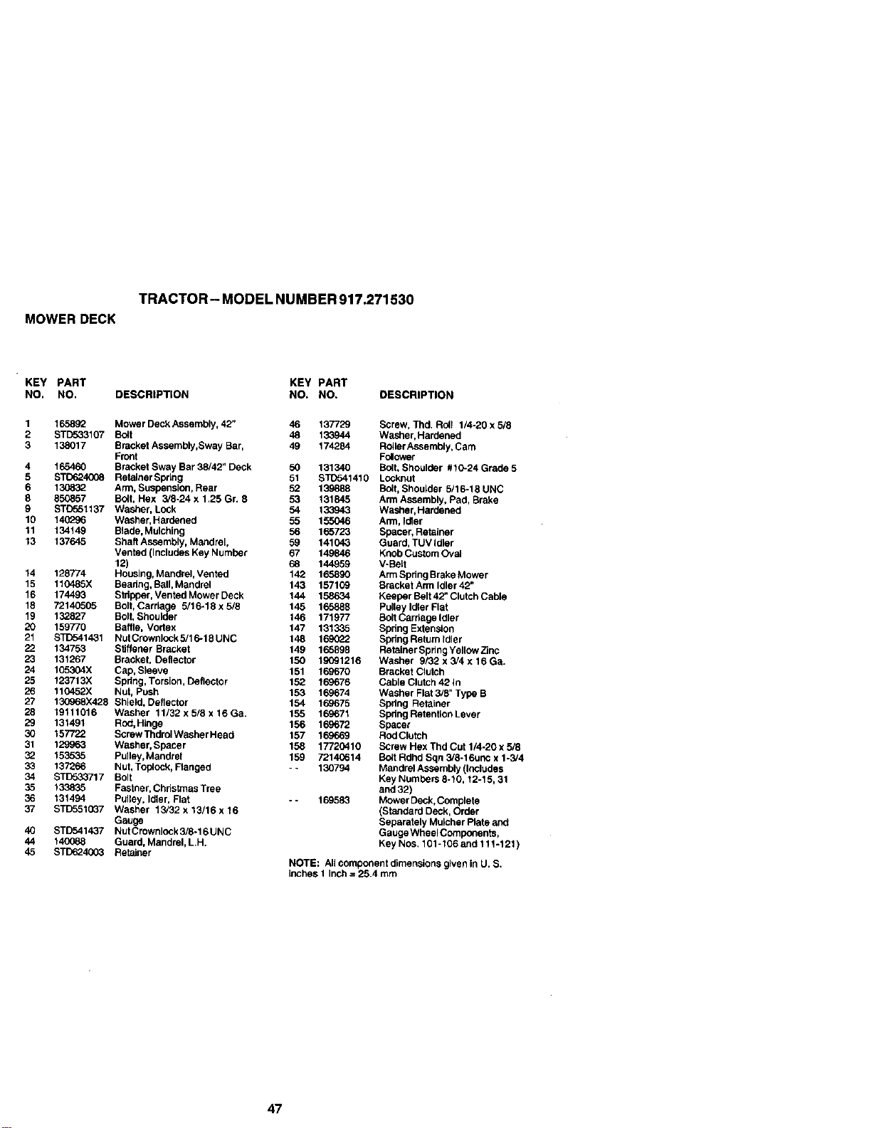
TRACTOR - MODEL NUMBER 917.271530
MOWER DECK
KEY PART KEY PART
NO. NO, DESCRIPTION NO, NO. DESCRIPTION
1 165892 Mower Deck Assembly, 42" 46 137729 Screw, Thd. Roll 1/4-20 x 5/8
2 S'rD533107 Bolt 48 133944 Washer, Hardened
3 138017 Bracket Assembly,Sway Bar, 49 174284 Ro41erAssembly, Cam
Front Folower
4 165460 Bracket Sway Bar 38/42" Deck 50 131340 Bolt, Shoulder #10-24 Grade 5
5 6T{7o24008 RetainerSpdng 51 ST1)541410 Locknut
6 13(_32 Arm, Suspension, Rear 52 139888 Bolt, Shoulder 5/16-18 UNC
8 85_857 Bolt, Hex 3/8-24 x 1,25 Gr. 8 53 131845 Arm Assembly, Pad, Brake
9 STC551137 Washer, Lock 54 133943 Washer, Hardened
10 140296 Washer, Hardened 55 155046 Arm, Idler
11 134149 Blade, Mulching 56 165723 Spacer, Retainer
13 137645 Shaft Assembly, Mandrel, 59 141043 Guard, TUV Idler
Vented (Includes Key Number 67 149846 Knob Custom Oval
12) 68 144959 V-Beff
14 128774 Housing, Mandrel, Vented 142 165890 Arm Spring Brake Mower
15 110485X Beadng, Ball, Mandrel 143 157109 Bracket Arm Idler 42"
16 174493 Stdpper, Vented Mower Deck 144 158634 Keeper Belt 42" Clutch Cable
18 72140505 Bolt, Carriage 5/16-18 x 5/8 145 165888 Pulley Idler Flat
19 132827 Bolt, Shoulder 146 171977 Bolt Cardage Idler
20 159770 Baffle, Vortex 147 131335 Spdng Extension
21 STD541431 NutCrownlock5/16-18UNC 148 1690_2 SpdngRetumldler
22 134753 Stiffener Bracket 149 165898 RetainerSpringYellowZinc
23 131267 Bracket, Deflector 150 19091216 Washer 9/32 x 5/4 x 16 Ga.
24 105304X Cap, Sleeve 151 169670 Bracket Clutch
25 123713X Spring, Torsion, Deflector 152 169676 Cable Clutch 42 in
26 110452X Nut, Push 153 169674 Washer Flat 3/8" Type B
27 130968X428 Shield, Deflector 154 169675 Spring Retainer
28 19111016 Washer 11/32x5/8x16Ga. 155 169671 SpdngReterdlonLever
29 131491 Rod, Hinge 156 169672 Spacer
30 157722 Screw Tndrol Washer Head 157 169669 RodClutch
31 129963 Washer, Spacer 158 17720410 Screw Hex Thd Cut 1/4-20 x 5/8
32 153535 Pufley,Mandtel 159 72146614 Bolt Rdhd Sqn 3/8-16unc x 1-3/4
33 137266 Nut, Toplock, Flanged - - 130794 Mandrel Assembly (Includes
34 STD533717 Bolt Key Numbers 8-10, 12-15, 31
35 133835 Fastner, Chdstmas Tree and 32)
36 131494 Pulley, Idler, Rat - - 169583 Mower Deck,Complete
37 STD5510_7 Washer 15/32 x13/16 x16 (Standard Deck, Order
Gauge Separately Muncher Rate and
40 STD541437 Nut Crownlock 3/8-16 UNC Gauge WheelC_npenents,
44 140088 Guard, Mandrel, LH. Key NOS, 101-106 and 111-121)
45 STD624003 Retainer
NOTE: All component dimensions given in U. S.
Inches 1 Inch = 25.4 mm
47
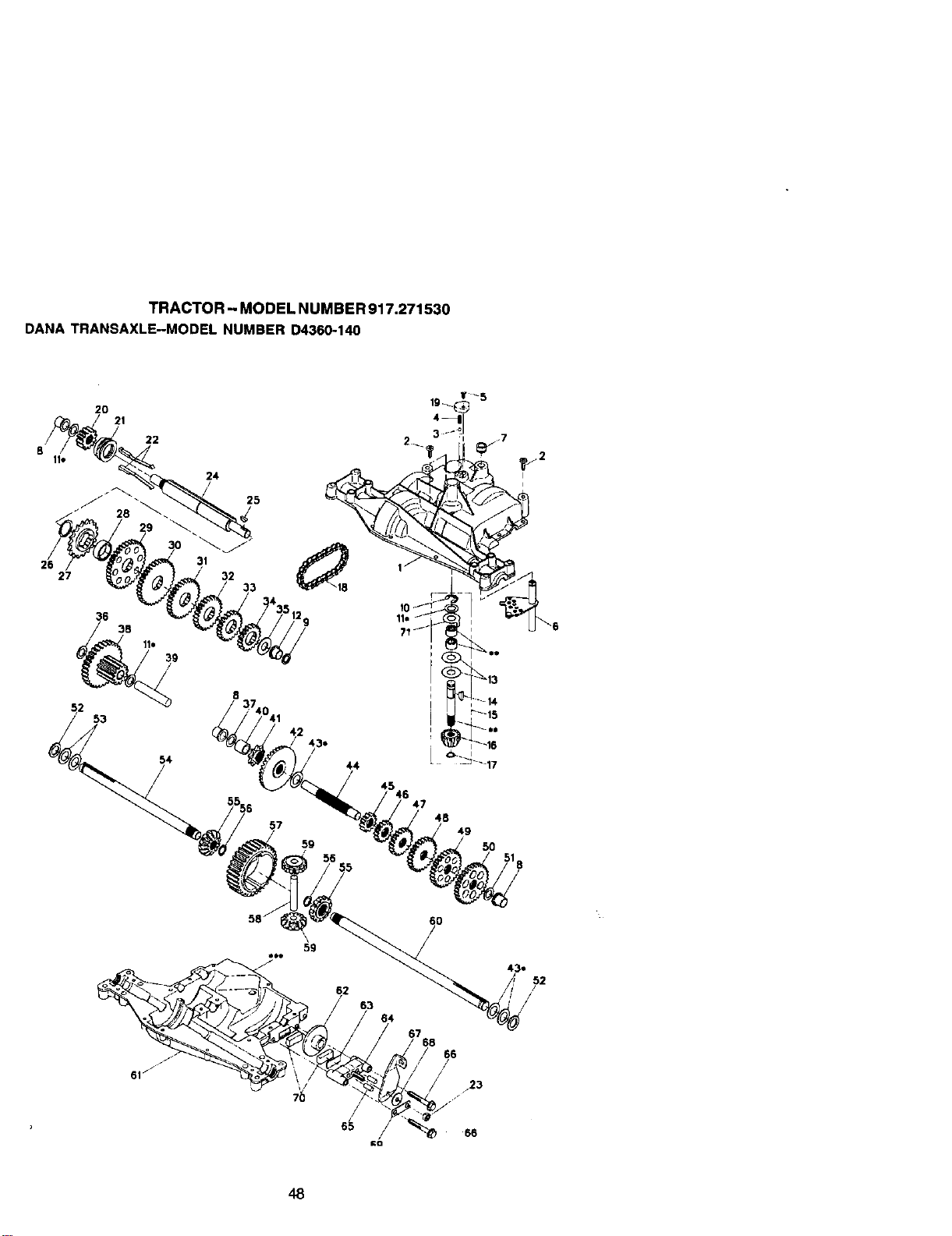
TRACTOR- MODELNUMBER917.271530
DANATRANSAXLE-MODELNUMBERD4360-140
20
21
22
24
27 32
54
/
/
8
25
48
49
5O
56
\
59
48
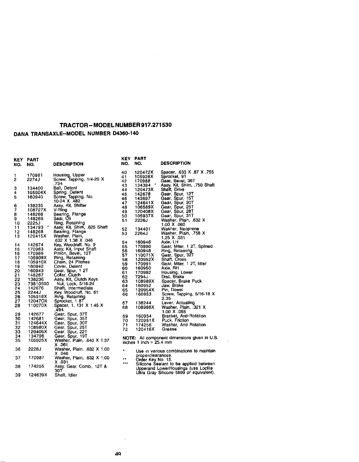
TRACTOR -- MODEL NUMBER 917.271530
DANA TRANSAXLE-MODEL NUMBER D4360-140
KEY PART KEY PART
NO. NO. DESCRIPTION NO. NO. DESCRIPTION
1 170981 Housing,,Upper 40 120472X Spacer, .633 X .87 X .755
41 105928X Sprocket, 9T
2 2274J Screw, Tapping, 1/4.20 X 42 170988 Dear, Bevel, 36T
.734 43 134394 * Assy, Kit, Shim, .750 Shaft
3 134400 Ball, Detent 44 120473X Shaft, Drive
4 105904X Spring, Detent 45 142678 Gear, Spur, 12T
5 160940 Screw, Tapping, No. 46 143697 Gear, Spur, 15T
10-24 X .482 47 12464tX Gear, Spur, 20T
6 138235 Ass, Kit, Shifter
7 108727X V-R_'n 48 106589X Gear, Spur, 25T
g 49 120408X Gear, Spur, 28T
8 148266 Bearing, Flange 50 105937X Gear, Spur, 31T
9 146269 Seal, Q_I 51 2226J Washer, Plain, .632 X
10 2225J Ring, Retaining 1.00 X .060
11 134793 " ASSy,Kit, Shim, .625 Shaft 52 13440t Washer, Neoprene
12 148268 Bearing, Flange 53 2264J Washer, Plain, .758 X
13 120415X Washer, Plain, 1.25 X .03t
.632 X 1.36 X .046 54 160946 Axle, LH
14 142674 Key,Woodruff, NO. 9 55 170990 Gear, Miter, 1 2T, Splined
15 170983 Assy, Kit, Input Shaft 56 160948 Ring, Retaining
16 170986 Pinion, Bevel, 12T
17 I05909X Ring, Retaining 57 110071X Gear, Spur, 32T
58 120952X Shaft, Cross
18 105910X Chain, 24 Pitches 59 170991 Gear, Miter, 1 2T, Idler
19 160942 Cover, Detent 60 160950 Axle, RH
20 160943 Gear, Spur, 1 2T
21 148267 Collar, Clutch 61 170992 Housing, Lower
62 7294J Disc, Br_ke
22 138236 ASSy,Kit, Clutch Keys 63 108989X Spacer, Brake Puck
23 73810500 Nut, Lock, 5/16-24 64 160952 Jaw, Brake
24 142676 Shaft, Intermediate 65 t20954X Pin, Dowel
25 2244J Key, Woodruff, No. 61 66 160953 Screw, Tapping, 5/16-18 X
26 105916X Ring, Retaining 2.35
27 12047OX Sprocket, 1 8T 67 138244 Lever, Actuating
28 110070X Spacer, 1. 131 X 1.45 X 68 108996X Washer, Plain, .321 X
.494 1.00 X .055
29 142677 Gear, Spur, 37T 69 160954 Bracket, Anti-Rotation
30 142681 Gear, Spur, 35T 70 120951X Puck, Friction
31 124644X Gear, Spur, 30T 71 174256 Washer, Anti Rotation
32 108980X Gear, Spur, 25T 72 120416X Grease
33 120406X Gear, Spur, 22T
34 134796 Gear, Spur, 19T NOTE: All component dimensions given in U.S.
35 105925X Washer, Plain, .640 X 1.37 inches 1 inch = 25,4 mm
X .061
36 2228J Washer, Plain, ,632 X 1,00 Use in various combinations to maintain
X .046 pro erclearances,
37 170987 Washer, Plain, .632 X 1.00 Or_
•* r Key No. 15.
X .031 *** Silicone Sealant to be applied between
38 174255 Ass, Gear, Comb., t2T &
3J_-y Upperand LowerHouaings use Loctite
39 124639X Shaft, Idler Ultra Gray Silicone 5699 or equivalent.
ZLCl
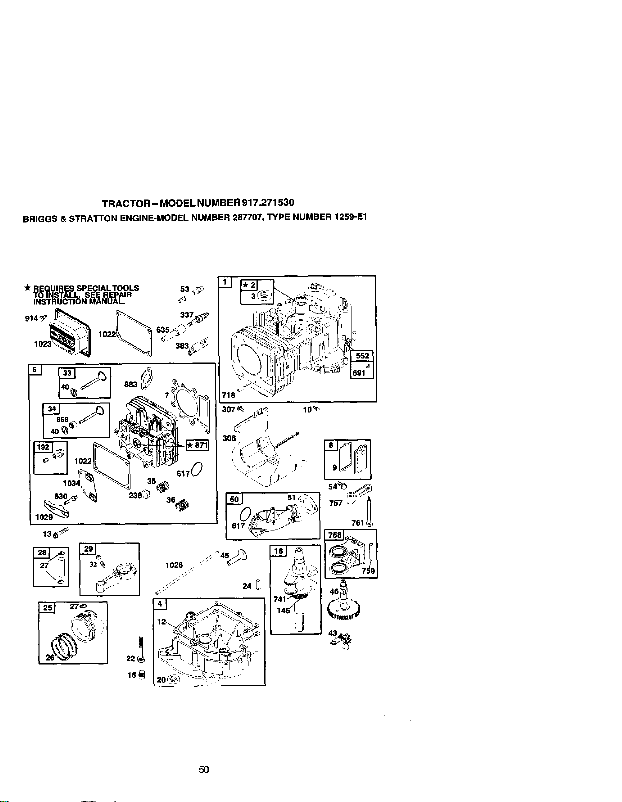
TRACTOR -- MODEL NUMBER 917.271530
BRIGGS& STRATTON ENGINE-MODELNUMBER287707, TYPE NUMBER 1259-E1
'_ REQUIRES SPECIALTOOLS 53 K_;_'
TO INSTALL. SEE REPAIR
INSTRUCTION MANUAL.
_',_ 1022 635_ _
883
617
35_?
307_ 10_
_911,
50
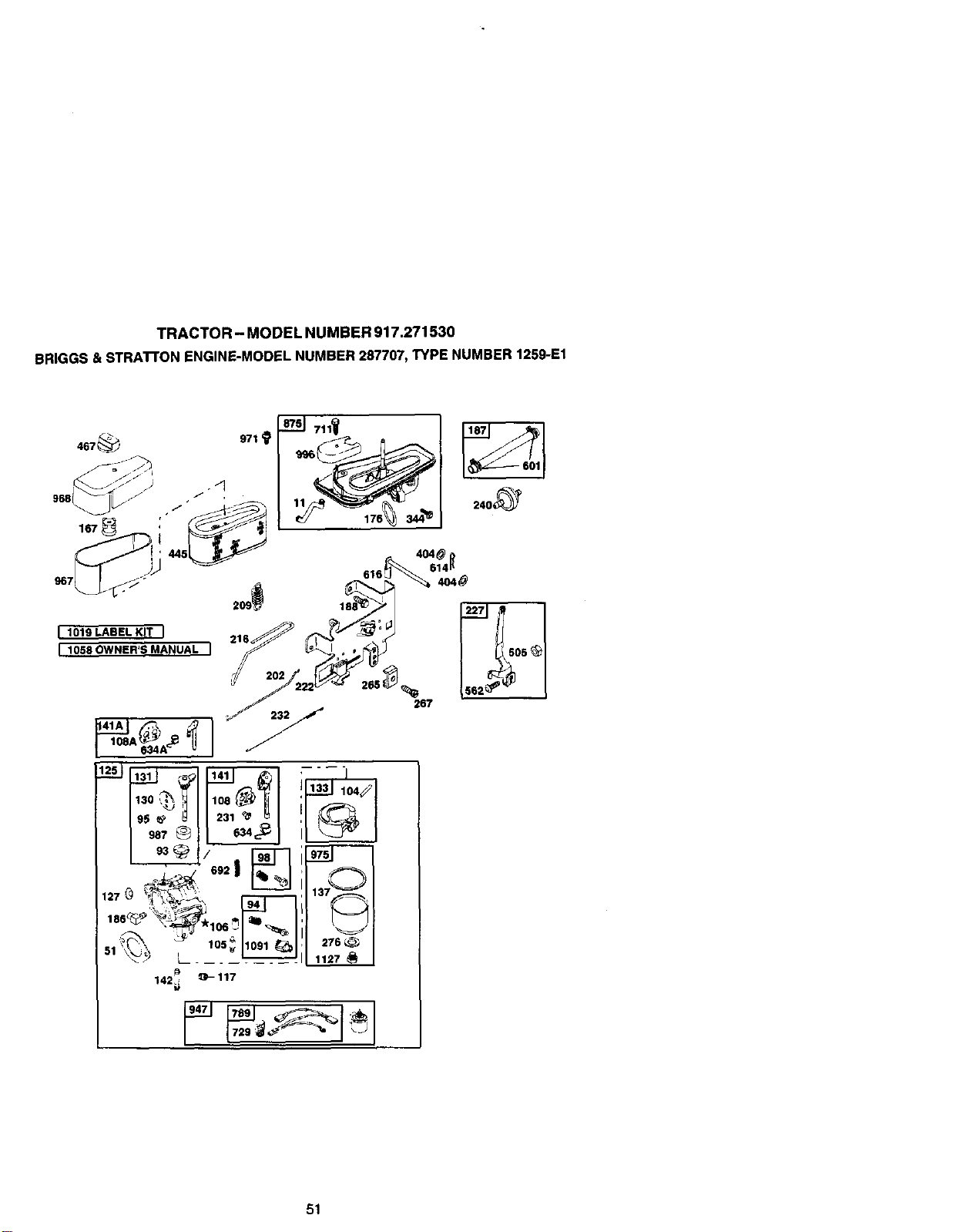
TRACTOR - MODEL NUMBER 917.271530
BRIGGS &STRA'rroN ENGINE-MODEL NUMBER287707, TYPE NUMBER 1259-E1
I 1019 LABEL KIT I
I 1058OWNER'SMANUAL i
127
51
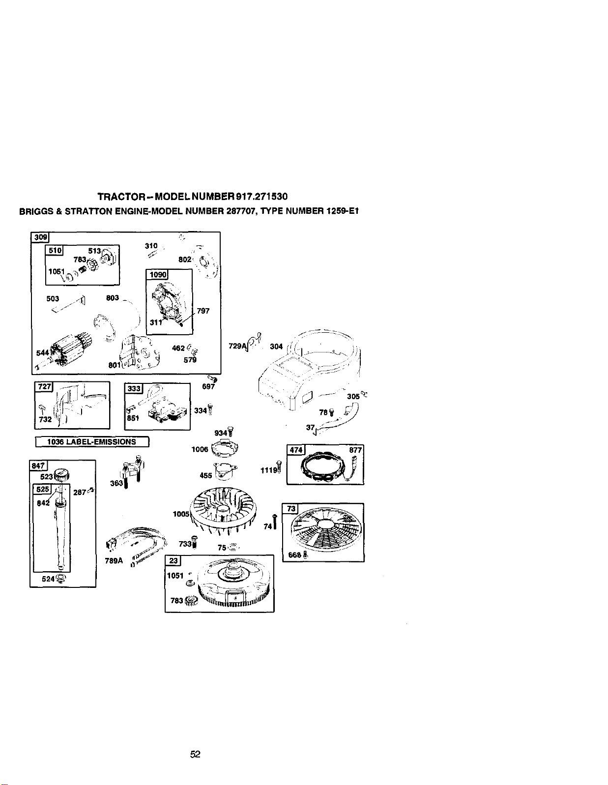
TRACTOR - MODEL NUMBER 917.271530
BRIGGS &STRATrON ENGINE-MODELNUMBER 287707,TYPE NUMBER 1259-E1
503 _ 803 _
_44_
3t0 _.,
802_ _ _ :,
1o9o , " o ,;
_797
[ 1036 LABEL-EMISSIONS ) 1006 @}
729A_! 304 [1 - ' o
I<
_- 305_. '
287.'_
524_
lOO,
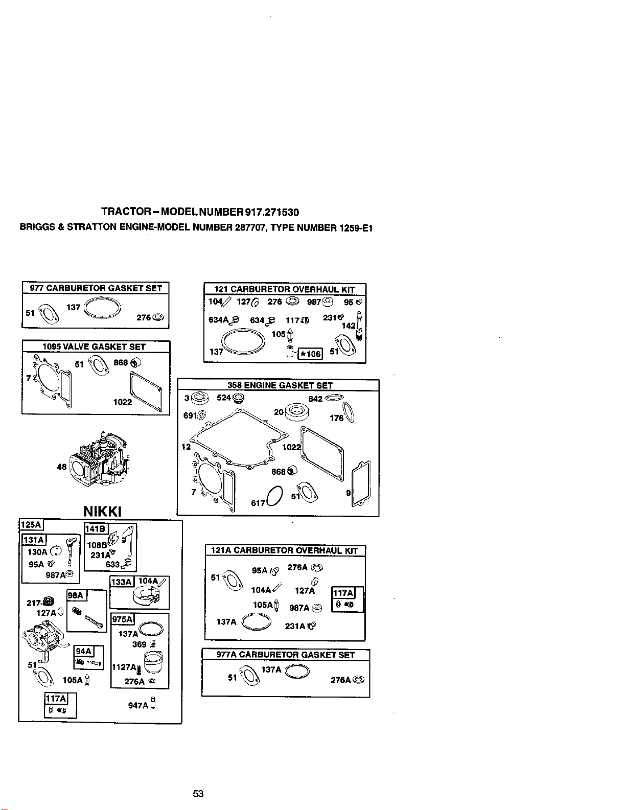
TRACTOR - MODE L NUMBE R917.271530
BRIGGS& STRATI'ON ENGINE-MODELNUMBER 287707,TYPE NUMBER 1259-E1
9_77CA. RBURE_RGASKET SET
51_ 137 0 276_--_
1095 VALVE GASKET SET
NIKKI
J
217_
127A
_,_ _ 137A-_
J_ 369
_ _ 1127A1_
_, 105A_ 276A _:_
121 CARBURETOR OVERHAUL KIT
104_ 127_ 276 _ 987_ 95
634A_ 634_ 117_ 231%42_
358 ENGINE GASKET SET
3 _ 524 _ 842
868
6170 5_
121A CARBURETOR OVERHAUL KIT
51_ 95A_ 276A_
104A_ 127A
lOSA 557A®
137A O 231A_
977A CARBURETOR GASKET SET I
51 '___ 276A _ /
J
53
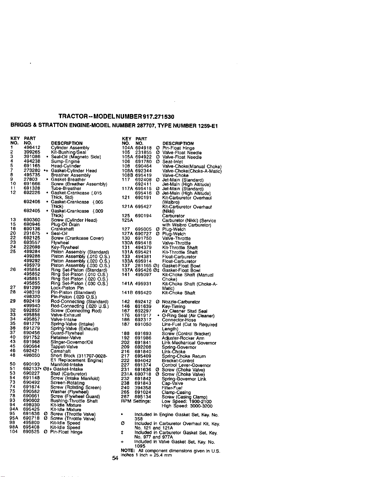
TRACTOR-- MODEL NUMBER 917.271530
BRIGGS& STRA'n'ON ENGINE-MODELNUMBER287707,TYPE NUMBER 1259-E1
KEY PART KEY PART
NO. NO, DESCRIPTION NO. NO. DESCRIPTION
1 496412 Cylinder Assembly t04A 694918 _ Pin-Float Hinge
2 399265 Kit-Bushing/Seal 105 231855 Q Valve-Float Needle
3 391086 , Seal-Oil (Magneto Sidel 105A 694922 Q Valve-Float Needle
4 494238 Sump-Engina 106 691780 Q Seat-Inlet
5 691165 Head-Cylinder 108 690464 Valve-Choke(Manual Choke)
7 273260 ,,4- Gasket-Cylinder Head 108A 692344 Valve-Choke(Choke-A-Matic)
8 495735 Breather Assembly 108B 695419 Valve-Choke
9 27803 • Gasket-Breather 117 692408 Q Jet-Main (Standard)
10 691666 SCTeW(Breathe_ Assembty) 692411 Jet-Main (High Altitude)
11 691328 Tube-Breather 117A 695419 (_ Jet-Main (Standard)
12 692226 • Gasket-Crankcase (.015 695416 O JehMain High Altitude)
Thick, Std) 121 690191 Kit-Carburetor Overhau
692406 • Gasket-Crankcase (.005 (Walbro
Thick) 121A 695427 Kit-Carburetor Overhau
692405 , Gasket-Crankcase (.009 (Nikki)
Thick) 125 690194 Carburetor
13 690360 Screw (Cylinder Head) 125A Carburetor (Nikki) (Service
15 690946 Plug-Oil Drain wilh WaVoroGaCm_reto_)
16 690136 Crankshaft 127 695005 Q Plug-Welch
20 291675 • Seal-Oil 127A 690727 O Plug-Welch
22 692125 Screw (Crankcase Cover) 130 691750 Valve-Throttle
23 693557 Flywheel 130A 695418 Valve-Throttle
24 222998 KeyoFlywheel 131 494379 Kit-Throttle Shaft
25 499284 Piston Assembly (Standard) 131A 695421 Kit-Throttle Shaft
499288 Piston Assembly (.010 O.S.) 133 494381 Float-Carburetor
499292 Piston Assembly (.020 O.S.) 133A 695914 Float-Carburetor
495979 Piston Assembly (.030 O.S.) 137 281165 O_: Gasket-Float Bowl
26 495854 Ring Set-Piston (Standard) 137A 695426 _t Gasket-Float Bowl
495852 Ring Set-Piston (.010 O,S,) 141 495097 Kit-Choke Shaft (Manual
495851 Ring Set-Piston (.020 O.S.) Choke
495855 Ring Set-Piston (.030 O.S.) 141A 495931 Ktl-Choke Shaft Choke-A-
27 891299 Lock-Piston Pin Matlc
28 498319 Pin-Piston (Standard) 141B 695420 Kit-Choke Shaf
498320 Pin-Piston (.020 O.S.)
29 692419 Rod-Connectir',g (Standard) 142 692412 (_ Nozzle-Carburetor
499940 Rod-Connecting (.020 U.S.) 146 691639 Key-Timing
32 692852 Screw (Connecting Rod) 167 692297 Air Cleaner Stud Seal
33 495856 Valve-Exhaust 176 691917 • O-Ring Seal (Air Cleaner)
34 495857 Valve-Intake 186 692317 Connector-Hose
35 691279 Spring-Valve (Intake) 187 691050 Line-Fuel (Cut to Required
36 691279 Spring-Valve (Exhaust) Length)
37 690456 Guard-Flywheel 188 691693 Screw (Control Bracket)
40 691752 Retainer-Valve 192 691986 Adjuster-Rocker Arm
43 691968 Snnger-Governor/Oi) 202 891841 Link-Mechan{cat Governor
45 690564 Tappet-Valve 209 692208 Sprin -Governor
46 692421 Camshaft 216 691840 Link-_:hoke
48 496050 Short Block (311707-0028- 217 695409 Spring-Choke Retum
E1 Replacement Engine) 222 694042 Bracket-Control
50 690193 Manifold-Intake 227 691374 Control Lever-Governor
51 692137, Or+ Gasket-Intake 231 691636 (_ Screw (Choke Vatve)
53 690227 Stud Carburetor) 231A 690718 (_ Screw (Choke Valve)
54 691149 Screw (Intake Maniold 232 691842 Spring-Governor Link
73 690492 238 691843 Cap-Valve
Screen-Rotating
74 691674 Screw (Rotating Screen) 240 394398 Filter-Fuel
75 690582 Washer (Flywheel) 265 891024 Clamp-Casing
78 690661 Screw (Flywheel Guard) 267 695134 Screw (Casing Clamp)
93 690602 Bushing-Throttle Shaft RPM Settings: Low Speed: 1900-2100
94 496030 K{t-ld_eMixture High Speed: 3000-3200
94A 695425 Kit-Idle Mixture
95 691636 _ Screw (Throttle Valve)
95A 690718 _ Screw (Throttle VaNe)
98 495800 Kit-Idle Speed
98A 695408 Kit-Idle Speed
104 690525 Q Pin-Ftoat Hinge
54
• Included in Engine Gasket Set. Key. No.
359
O Included in Carburetor Overhaul Kit. Key.
No. 121 and 121A
t Included in Carburetor Gasket Set, Key,
No. 977 and 977A
+ Included in Valve Gasket Set. Key. NO.
1095
NOTE: All component dimensions given in U.S.
Inches 1 inch = 25.4 mm
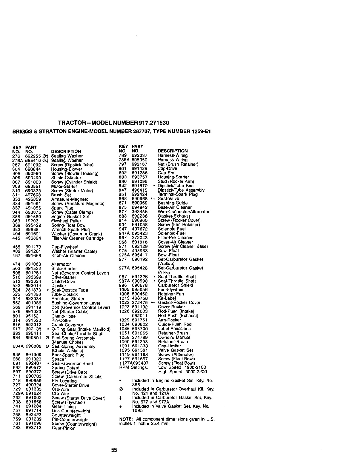
TRACTOR - MODEL NU MBER 917.271530
BRIGGB & STRAI-rON ENGINE-MODELNUMBER287707, TYPE NUMBER 1259-E1
KEY PART KEY PART
NO. NO. DESCRIPTION NO. NO. DESCRIPTION
276 892255 _:_ Sealing Washer 789 692037 Harness-Wiring
276A 695410 Ot SealJng Washer 789A 695050 Harness-Wiring
287 691002 Screw (DipstickTube) 797 693167 Nut (Brush Retainer)
364 690844 Housing-BlOwer 801 691429 Cap-Drive
305 690960 Screw (Blower Housing) 802 691286 Cap-End
306 690499 Shield-Cylinder 803 693757 Housing-Starter
307 691003 Screw(Cylinder Shield) 830 691095 Stud (Rocker Arm)
309 693551 Motor-Stader 842 691870 • Dipstick/Tube Seal
310 690323 Screw/_Stader Motor) 847 496415 Dipstick/Tube Assembly
311 497608 Brush Set 851 692424 Terminal-Spark Plug
333 496859 Armature-Magneto 868 690968 *+ Seal-Valve
334 591061 Screw (Armature Magneto) 871 690969 Bushing-Guide
875 694942 Base-Air Cleaner
337 491055 Spark PI_ °
344 693676 Screw (C _eClamp) 877 393456 Wire-C0nnector/Aiternator
358 891580 Engine Gasket Set 883 692236 Gasket*Exhaust
363 19203 Flywheel Puller 914 690960 Screw (RoCkerCover)
369 695422 Spring-Float Bowl 934 691058 Screw Fan Retainer)
383 69838 Wrench-Spark Plug 947 497672 Solenoid-Fue
404 691691 Washer (Governor Crank) 947A 695423 Solenoid*Fuel
445 496894 Filter-Air Cleaner Cadridge 967 272043 Filter-Pre Cleaner
968 691916 Cover-Air Cleaner
971 692129 Screw (Air Cleaner Base)
455 691173 Cup-Flywheel
462 691261 Washer Stader Cable) 975 495933 Bowl-Float
467 691888 Knob-Air Ceaner 975A 695417 Bowl-Float
977 690192 Set-Carburetor Gasket
474 691063 Alternator Walbro)
503 691532 Strap-Starter 977A 695428 Set-Carburetor Gaske
505 691251 Nut (Governor Control Lever) (Nikki)
510 693699 D_we-Starter 967 691326 • Seal-Throttle Shaft
513 692024 Clutch-Drive 987A 690998 • Seal-Throttle Shaft
523 692014 Dipstick 996 690678 Carburetor Shield
524 291370 • Seal-Dipstick Tube 1005 695056 Fan-Flywheel
525 691398 Tube-Dipstick 1006 690452 Retainer-Fan
544 692034 Armature-Starter 1019 496758 Kit-Label
552 491986 Bushing-Governor Lever 1022 272475 ,+ Gasket-Rocker Cover
562 691119 Bolt Governor Control Lever) 1023 691192 Cover-Rocker
579 691029 Nut (Stadsr Cabs) 1026 692003 Rod-Push Intake)
692011 Rod-Push Exhaust
601 95162 Clamp-Rose
614 691620 Pin-Cotter 1029 691751 Arm-Rocker
616 692612 Crank-Governor 1034 690822 Guide-PuSh Rod
617 692138 ° O-Ring Seal (Intake Manifold) 1036 695700 Label-Emissions
633 695414 Seal-Choke/Throttle Shaft 1051 691265 Retainer-Brush
634 690801 O Seal*Spring Assembly 1058 274789 Owner's Manual
(Manual Choke) 1090 691293 Retainer-Brush
634A 690802 O Seal-Spring Assembly 1091 691333 Cap-Limiter
(Choke-A-Matic) 1095 691581 Valve Gasket Set
635 691909 Boot-Spark Plug 1119 691183 Screw Alternator)
668 691323 Spacer 1127 691657 Screw(Foa Bow
691 692407 ° Seal-Governor Shaft 1127A695407 Screw (Ftoat Bowt)
692 690572 Spring-Detent RPM Settings: Low Speed: 1900-2100
697 690372 Screw (Drive Cap) High Speed: 3000-3200
711 690703 Screw (Carburetor Shield)
718 690959 Pin-Locating
727 490324 Cover-Starter Drive
729 891335 Clip-Wire
729A 691224 Clip-Wire
732 691002 Screw (Starter Drive Cover)
733 691658 Screw (Flywheel)
741 691284 Gear-Timing
757 691714 Link-Counterweight
758 692423 Counterweight
759 691239 Pin-Counterweight
761 691096 Screw (Counterweight)
783 693713 Gear-Pinion
Included in Engine Gasket Set, Key. No.
366
O Included in Carburetor Overhaul Kit, Key.
NO. 121 and 121A
:t Included in Carburetor Gasket Set, Key.
No. 977 and 977A
+ Included in Valve Gasket Set, Key. No.
1095
NOTE: All component dimensions given in U.S.
inches 1 inch = 25.4 mm
55


57


SUGGESTED GUIDE FOR SIGHTING SLOPES FOR SAFE OPERATION
SIGHTING _"
GUIDE
ONLY RIDE UP AND DOWN HILL,
NOT ACROSS HILL
_ Operate your Tractor up and down the face of slopes (not I
_J_ greater than 15°), never across the face. Make turns gredu- I
ally to prevent tipping or loss of control. Exercise extreme I
caution when changing direction on slopes. I
I

Get it fixed, at your home or ours!
Forrepair of major brand appliances in your own home...
no matter who made it, no matter who sold it!
1-800-4-MY-HOME SM Anytime, day or night
(1-800-469,,4663)
www.sears.com
To bring in products such as vacuums,
lawn equipment and electronics for repair, call for
the location of your nearest Sears Parts & Repair Center.
1-800-488-1222 A.yt_r.e,dayor night
www.sears.com
Forthe replacement parts, accessories and owner's manuals
that you need to do-it-yourself, call Seers PartsDirectSM!
1-800-366-PART 6ar.- _ pr. CST
(1-800-366-7278) 7 daysa week
www.sears.corn/partsdlrect
To purchase or inquire about a Sears Service Agreement:
1-800-827-6655
7 a.m.- 5 p.m.CST,Mort.- Sat,
Para pedirserviciode reparacibn a dornicilio,
y para ordenarpiezas con entrega a domlcillo:
1-888-SU-HOGAR _
(1-888-784-6427)
Au Canada pour service en fran_:ais:
1-877-LE-FOYERs"
(1-877-533-6937)
SEARS
H°meCentral ® }
® Sears, Roebuck and Co.
® Registered Trademark / Trademark of Sears, Roebuck and Co
TM R
® Marca Regislrada / Marca de Fttbdca de Sears, oeduck and Co.
177089 Rev.1 11.16.(_(_..l_I_BTRC Printed in U.S.A.


