
--_ ,,=,,, v r
Caution:
Read and follow
all Safety Rules
and Instruct=ons
Before Operating
This Equipment
®
12.0 HP IC
ELECTRUC START
38" MOWER DECK
5 SPEED TRANSAXLE
LAWN TRACTOR
, Assembly
• Operation
• Maintenance
° Service and Adjustment
• Repair Parts
Sears, Roebuck and Co., Chicago, IL 60684 U.S.A.
&
SAFETY RULES
CAUTION: ALWAYS DISCONNECT SPARK PLUG WIRE AND PLACE WIRE WHERE IT CANNOT CONTACT SPARK
PLUG TO PREVENT ACCIDENTAL STARTING WHEN SETTING-UP_ TRANSPORTING, ADJUSTING OR MAKING
REPAIRS.
aMPORTANT
SAFETY STANDARDS REQUIRE OPERATOR PRESENCE CONTROLS TO MINIMIZE THE RISK OF INJURY. YOUR UNIT IS EQUIPPED WITH SUCH
CONTROLS_ DO NOT ATTEMPT TO DEFEAT THE FUNCTION OF THE OPERATOR PRESENCE CONTROLS UNDER ANY CIRCUMSTANCES,
TRAINING:
Know the controlsand how to stop quickly. Read U]is owner's
manual and instructions furnished with attachments,
Do not allow children to operate the machine Do not allow
adults to operate it without proper instruction.
Do not carry passengers_ Do net mow when children and
others are around.
Do not attempt to operate your vehicle or mower when not in
the driver's seal
Always get on or off your vehicle from the operator's left hand
side.
The vehicle and attachments should be stopped and in-
spected for damage after striking a foreigrl object, and ftle
damage should be repaired before restarting and operating
the equipment
PREPARATION:
Always wear substantial footwear. Do not wear loose fitting
clothing that could get caught in moving parts
Clear the work area of objects (wire, rocks, etc.) which might
be picked up and thrown.
Disengage all attachment clutches before attempting to start
the engine
Handle gasoline with care. it is highly flammable
Use approved gasoline containers.
Never remove the fuel cap of the fuel tank or add gasoline
to a running or hot engine or an engine that has not been
allowed to cool for several minutes after running Never
fill tank indoors Always clean up spilled gasoline
Open doors if the engine is run in the garage - exhaust
fumes are dangerous Do not run the engine indoors i
Do not operate the mower without the entire grass catcher i
on mowers so equ pped, or the deflector shield in place
OPERATION:
Keep your eyes and mind on your vehicle, mower and the'
area being cut. Do not let other interests distract you.
Disengage power to attachments and stop the engine before
leaving the operator's position
Disengage power to mower, stop the engine, and disconnect
spark plug wire(s) from spark plug s;)before cleaning making
an adjustment, or repair Be careful to avoid touching hot
muffler or engine components.
Disengage power to attachments when transporting or not in
usa
Take all possible precautions when leaving the vehicle unat-
tended Disengage the power take-off, lower the attach-
ments, shift into neutral, set the parking brake, stop the
engine, and remove the key.
Do not stop or start suddenly when going uphill or downhill
Mow up and down the face of slopes (not greater than 15°),
never across the face,
Reduce speed on slopes and make turns gradually to prevent
tipping or loss of control Exercise extreme caution when
changing direction on slopes
While going up or down slopes, place gearshift control lever
in 1st gear position to negotiate the slope without stopping,
Never mow inwet or slippery grass, when traction is unsure,
or at a speed which could cause a skid
Stay alert for holes in the terrain and other hidden hazards_
Keep away from drop-offs
Do not drive too close to creeks, ditches, and public high-
ways,
Exercise special care when mowing around fixed objects in
order to prevent the blades from striking them Never delib-
erately run vehicle or mower intoor over any for eign objects
Never shift gears until vehicle comes to a stop
Never place hands or feet under the mower, in discharge
chute, or near any moving parts while vehicle or mower is
running Always keep clear of discharge chute
Use care when pulling loads or using heavy equipment
Usa only approved drawbar hitch points
Limit loads to those you can safely control
Do not turn sharply Use care when backing
Use counterweight orwheel weights when suggested in
owner's manual
Watch out for traffic when crossing or near roadways
When using any attachments, never direct discharge of
material toward bystanders nor allow anyone near the ve-
hicle while in operation
Except for adjustments, do not operate engine ifair cleaner
or cover directly over carburetor air intake is removed
Removal of such part could create a fire hazard
Do not change the engine governor settings or overspeed
the engine; severe damage or injury may result
When using the vehicle with mower, proceed as follows:
Mow only in daylight or in good artificial light
Shut the engine off when unclogging chute.
Check the blade mounting bolts for proper tightness at
frequent intervals
Disengage power to mower before backing up Do not mow
in reverse unless absolutely necessary and then only after
careful observation of the entire area behind the mower,
MAINTENANCE AND STORAGE
Keep the vehicle andattachments in good operating condi-
tion, and keep safety devices in place and working.
Keep all nuts, bolts, and screws tight to be sure the equip-
ment is in safe working condition,
Never store theequipment with gasoline in thetank insidea
building where fumes may reach an open flame or spark
Allow the engine to cool before storing in any enclosure
Toreducefire hazard, keep theengineft eeofgrass, leaves,
or excessive grease Do not clean productwhile engine is
running.
Do not operate without a muffler, or tamper with exhaust
system Damaged mufflers or spark arrestorscouldcreatea
fire hazard, inspect periodicallyand replaceif necessary,
Under normal usage the grass catcher bag material is
sub ect to deterioration and wear. It should be checked
frequent yfor bag replacement Replacement bags should
be checked to ensure compliance with the original
manufacturer's recommendationsor specifications,
I ,_ LOOK FOR THIS SYMBOLTO POINT OUT IMPORTANT SAFETY PRECAUTIONS.
IT MEANS - ATTEN'I"IONll! BECOME ALERTI!I YOUR SAFETY IS INVOLVED.
2

CONGRATULATIONS on your purchase of a Sears
Tractor_ it has been designed, engineered and manu-
factured to give you the best possible dependability and
performance
Should you experience any problem you cannot easily
remedy, please contact your nearest Sears Service
Center/Department. We have competent, well-trained
technicians and the proper tools to service or repair this
unit_
Please read and retain this manual The instructions will
enable you to assemble and maintain your unit properly.
Always observe the "SAFETY RULES".
MODEL
NUMBER 917257470
SERIAL
NUMBER
DATE OF PURCHASE
THE MODELAND SERIAL NUMBERS WILL BE FOUND
ON A PLATE UNDER THE SEAT.
YOU SHOULD RECORD BOTH SERIAL NUMBER AND
DATE OF PURCHASE AND KEEP IN A SAFE PLACE
FOR FUTURE REFERENCE.
MAINTENANCE AGREEMENT
A Sears Maintenance Agreement is available on this prod-
uct. Contact your nearest Sears store for details.
CUSTOMER RESPONSIBILITIES
Read and observe the safety rules
Follow a regular schedule in maintaining, caring for and
using your unit
Follow the instructions under "Maintenance" and
"Storage" sections of this owner's manual
PRODUCT SPECIFICATIONS
HORSEPOWER: 12 0
GASOLINE CAPACITY: 5 QUARTS
UNLEADED REGULAR
OIL (3 0 PINTS): SAE 30 (or 10W-30)
WINTER: SAE 5W-30
SPARK PLUG (GAP 030 IN ): CHAMPION RJ-19LM
STD361458
VALVE CLEARANCE: INTAKE O05- OO7IN
EXHAUST 009- 011 IN
GROUND SPEED: FORWARD
1st 1 10 MPH
2nd 2 00 MPH
3rd 3 00 MPH
4th 4 0OMPH
5th 5 00 MPH
REVERSE: 150 MPH
TIRE PRESSURE: FRONT: 14 PSi
REAR: 10 PSI
CHARGING SYSTEM: 3 AMPS BA'FrERY
5 AMPS HEADLIGHTS
BLADE BOLT TORQUE: 30-35 FT LBS
WARNING: This unit is equipped with an internal combus-
tion engine and should not be used on or near any unim-
proved forest-covered, brush-covered or grass-covered
land unless the engine's exhaust system is equipped with
a spark arrester meeting applicable local or state laws (if
any) If a spark arresteris used, it should be maintained in
effective working order by the operator
tn the state of California the above is required by law
(Section 4442 of the California Public Resources Code)
Other states may have similar laws Federal taws apply on
federal lands A spark arrester for the muffler is available
through your nearest Sears Authorized Service Center
(See REPAIR PARTS section of this manual)
LIMITED TWO YEAR WARRANTY ON ELECTRIC START RIDING EQUIPMENT
For two years from date of purchase, when this riding equipment is maintained, lubricated, and tuned up according to the
operating and maintenance instructions in the owner's manuel, Sears will repair free of charge any defect in material or
workmanship
This Warrantydoes not cover:
Tire replacement or repair caused by puncturesfrom outside objects (such as nails, thorns, stumps, or glass)
Expendableitems which becomeworn during normaluse, such asblades, spark plug, air cleaners and belts
Repairs necessary because of operator abuse or negligence, including bent crankshafts and the failure to maintain the
equipmentaccording to the instructionscontained in the owner's manual
Ridingequipment usedfor commercial or rentalpurposes
FULL 90 DAY WARRANTY ON BATTERY
For90 days from date of purchase,if any batteryincludedwith this riding equipment proves defective in material or workmanship
and our testing determines the batterywill not hold a charge, Sears will replace the batteryat no charge
WARRANTY SERVICE ISAVAILABLE BY CONTACTINGTHE NEAREST SEARS SERVICE CENTER/DEPARTMENT IN THE
UNITED STATES THIS WARRANTY APPLIES ONLY WHILETHIS PRODUCTIS IN USE INTHE UNITED STATES
This Warranty gives youspecific legal rights, and you may also haveother rights which vary from stateto state
SEARS, ROEBUCK AND CO, D/731CR-W SEARS TOWER, CHICAGO, IL 60684
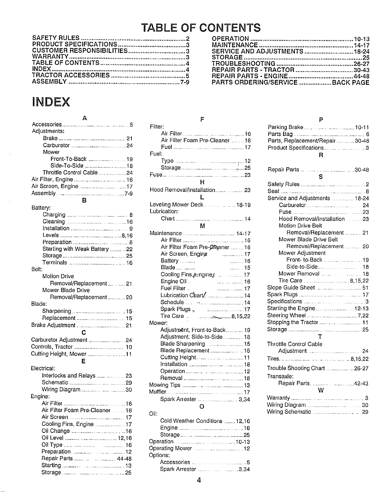
TABLE OF CONTENTS
SAFETY RULES ............................................................ 2
PRODUCT SPECIFICATIONS ....................................... 3
CUSTOMER RESPONSIBILITIES ................................. 3
WARRANTY ................................................................... 3
TABLE OF CONTENTS ................................................. 4
INDEX ............................................................................. 4
TRACTOR ACCESSORIES ........................................... 8
ASSEMBLY ................................................................ 7-9
OPERATION ........................................................... 10=13
MAINTENANCE ...................................................... 14-17
SERVICE AND ADJUSTM ENTS ............................ 18-24
STORAGE .................................................................... 25
TROUBLESHOOTING ............................................ 26-27
REPAIR PARTS - TRACTOR ................................. 30-43
REPAIR PAR'I"S - ENGINE ..................................... 44-48
PARTS ORDERING/SERVICE ................... BACK PAGE
HNDEX
A
Accessories ............................................... 5
Adjustments:
Brake ..................................................21
Carburetor. ................................. 24
Mower
Front-To-Back ....................... 19
Side-To-Side ............................ 18
Throttle Control Cable ................... 24
Air Filter, Engine ......................................16
Air Screen, Engine ..................................17
Assembly .................................................7-9
B
Battery:
Charging ......................................... 8
Cleaning .......................................... 16
Installation ......................................... 9
Levels ........................................... 8,16
Preparation .................................... 8
Starting with Weak Battery ......... 22
Storage ......................................... 25
Terminals ..........................................16
Belt:
Motion Drive
Removal/Replacement ........ 21
Mower Blade Drive
Removal/Replacement ...............20
Blade:
Sharpening ...................................... 15
Replacement .....................................15
Brake Adjustment ............................... 21
C
Carburetor Adjustment ............................24
Controls, Tractor ..................................... 10
Cutting Height, Mower .......................... 11
E
Electrical:
Interlocks and Relays ................. 23
Schematic ..................................... 29
Wiring Diagram ............................. 30
Engine:
Air Filter ......................................... 16
Air Filter Foam Pre-Cleaner .... 16
Air Screen ...................................... 17
Cooling Fins, Engine ..................... 17
Oil Change ........................................16
Oil Level ......................................12,16
Oil Type ........................................ 16
Preparation ................................. 12
Repair Parts ............................. 44-48
Starting ........................................... 13
Storage .................................... 25
F
Filter:
Air Filter .......................................... 16
Air Filter Foam Pre-Cleaner, ...... 16
Fuel ........................................................17
Fuel:
Type ...................................... 12
Storage ..................................... _._,25
Fuse .................................................. 23
H
Hood Removal/Installation .............. 23
L
Leveling Mower Deck ............. 18-19
Lubrication:
Chart ........................................... 14
M
Maintenance ........................................14.17
Air Filter. ..................................... 16
Air Filter Foam Pre-J2_aner ........ 16
Air Screen, Engin_ .............. 17
Battery .................. 16
Blade ................. 15
Cooling Fins,l_-ngEne/ ........... 17
Engine Oil ................. 16
Fuel Filter ..................... 17
Lubrication Chart! ............................14
Schedule --, ............................. 14
Spark Plugs., ,.................... 17
Tire Care ......... ..-,-..._...,..8,15,22
Mower:
Adjustment, Front-to-Back ........... 19
Adjustment, Side.to-Side ................18
Blade Sharpening ........................ 15
Blade Replacement ...................... 15
Cutting Height ................................. 11
Installation ..................................... 18
Operation .................................. 12
Removal .......................................... 18
Mowing Tips ......................................... 13
Muffler ........................................... 17
Spark Attester ........................... 3,34
o
Oil:
Cold Weather Conditions ....... 12,16
Engine ........................................ 16
Storage ................................................25
Operation .................................. 10-13
Operating Mower .......................... 12
Options:
Accessories ....................... 5
Spark Arrester .................... 3,34
4
P
Parking Brake .............................. 10-11
Parts Bag ................................................6
Parts, Replacement!Repair ............30-48
Product Specifications.......................... 3
R
Repair Parts ............................... 30-48
S
Safety Rules ................................... 2
Seat .................................................... 8
Service and Adjustments ............... 18-24
Carburetor ............................ 24
Fuse ........................................... 23
Hood Removal/Installation ....... 23
Motion Drive Belt
Removal/Replacement ..............21
Mower Blade Drive Belt
Removal/Replacement ........ 20
Mower Adjustment
Front- to-Back ..................... 19
Side-to-Side .............. 18
Mower Removal ............. 18
Tire Care ............................. 8,15,22
Slope Guide Sheet ............................. 51
Spark Plugs ....................................... 17
Specifications ..................... 3
Starting the Engine ......................... 12-13
Steering Wheel ................................ 7,22
Stopping the Tractor ....................................11
Storage ................................................ 25
T
Throttle Control Cable
Adjustment ............................. 24
Tires.................................................. 8,15,22
Trouble Shooting Chart ................... 26-27
Transaxle:
Repair Parts .......................... 42-43
W
Warranty ........................................... 3
Wiring Diagram .............................. 30
Wiring Schematic ............................. 29
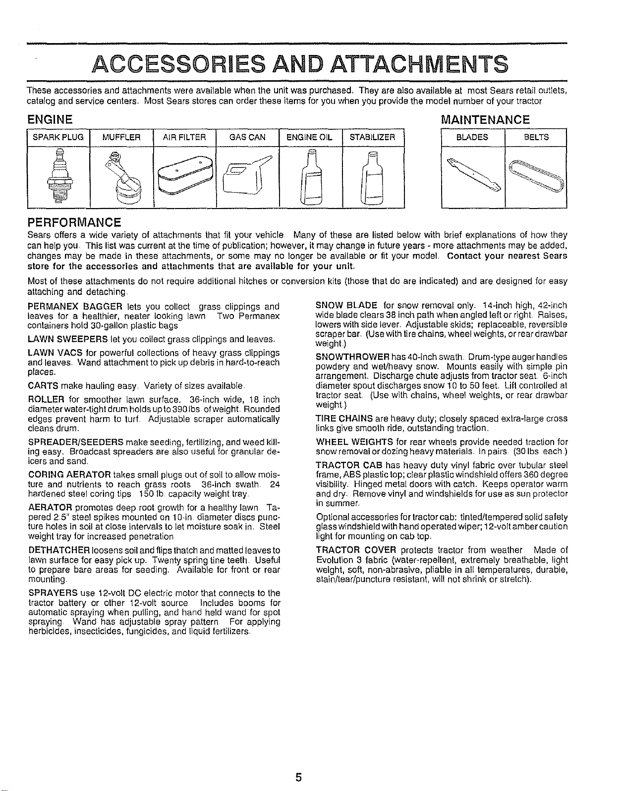
ACCESSORBES AND ATTACHMENTS
These accessories and attachments were available when the unit was purchased. They are also available at most Sears retail outIets,
catalog and service centers, Most Sears stores can order these items for you when you provide the model number of your tractor
ENGINE
SPARK PLUG MUFFLER AIR FILTER GAS CAN ENGINE OIL STABILIZER
MAINTENANCE
BLADES BELTS
PERFORMANCE
Sears offers a wide variety of attachments that fit your vehicle Many of these are listed below with brief explanations of how they
can help you. This list was current at the time of publication; however, it may change in future years - more attachments may be added,
changes may be made in these attachments, or some may no longer be available or fit your model. Contact your nearest Sears
store for the accessories and attachments that are available for your unit,
Most of these attachments do not require additional hitches or conversion kits (those that do are indicated) and are designed for easy
attaching and detaching
PERMANEX BAGGER lets you collect grass clippings and
leaves for a healthier, nearer looking lawn Two Permanex
containers hold 30-gallon plastic bags
LAWN SWEEPERS let you collect grass clippings and leaves.
LAWN VACS for powerful collections of heavy grass clippings
and leaves Wand attachment to pick up debris in hard.to-reach
places.
CARTS make hauling easy. Variety of sizes available
ROLLER for smoother lawn surface, 36-inch wide, 18 inch
diameterwater-tightdrumholdsupto3901bs ofweight. Rounded
edges prevent harm to turf. Adjustable scraper automatically
cleans drum,
SPREADER/SEEDERS make seeding, fertilizing, and weed kill-
ing easy, Broadcast spreaders are also useful for granular de-
icers and sand,
CORING AERATOR takes small plugs out of soil to allow mois-
ture and nutrients to reach grass roots 36-inch swath. 24
hardened steel coring tips 150 Ib capacity weight tray
AERATOR promotes deep root growth for a healthy lawn Ta-
pered 25" steel spikes mounted on 10-in diameter discs punc-
ture holes in soil at close intervals to let moisture soak in. Steel
weight tray for increased penetration
DETHATCHER loosens soil and flips thatch and matted leaves to
lawn surface for easy pick up. Twenty spring tine teeth. Useful
to prepare bare areas for seeding, Available for front or rear
mounting
SPRAYERS use 12-volt DC electric meter that connects to the
tractor battery or other 12-volt source Inciudes booms for
automatic spraying when pulling, and hand held wand for spot
spraying Wand has adjustable spray pattern For applying
herbicides, insecticides, fungicides, and liquid fertilizers
SNOW Bt.ADE for snow removal only. 14-inch high, 42-inch
wide blade clears 38 inch path when angled left or right Raises,
lowers with side lever. Adjustable skids; replaceable, reversible
scraper bar (Use with tire chains, wheel weights, or rear drawbar
weight)
SNOWTHROWER has 40-inch swath Drum-type auger handles
powdery and wet/heavy snow. Mounts easily with simple pin
arrangemenL Discharge chute adjusts from tractor seat 6-inch
diameter spout discharges snow 10 to 50 feel Lift controlled at
tractor seat (Use with chains, wheel weights, or rear drawbar
weight)
TIRE CHAINS are heavy duty; closely spaced extra-large cross
links give smooth ride, outstanding traction,
WHEEL WEIGHTS for rear wheels provide needed traction for
snow removal or dozing heavy materials. In pairs (30 Ibs each )
TRACTOR CAB has heavy duty vinyl fabric over tubular steel
frame, ABS plastic top; clear plastic windshield offers 360 degree
visibility. Hinged metal doors with catch. Keeps operator warm
and dry, Remove vinyl and windshields for use as sun protector
in summer_
Optionalaccessoriesfor tractorcab: tinted/tempered solidsafety
glasswindshield with handoperated wiper;12-volt ambercaution
light for mounting on cab top,
TRACTOR COVER protects tractor from weather Made of
Evolution 3 fabric (water-repellent, extremely breathable, light
weight, soft, non-abrasive, pliable in all temperatures, durable,
stain/tear/puncture resistant, will not shrink or stretch),
5
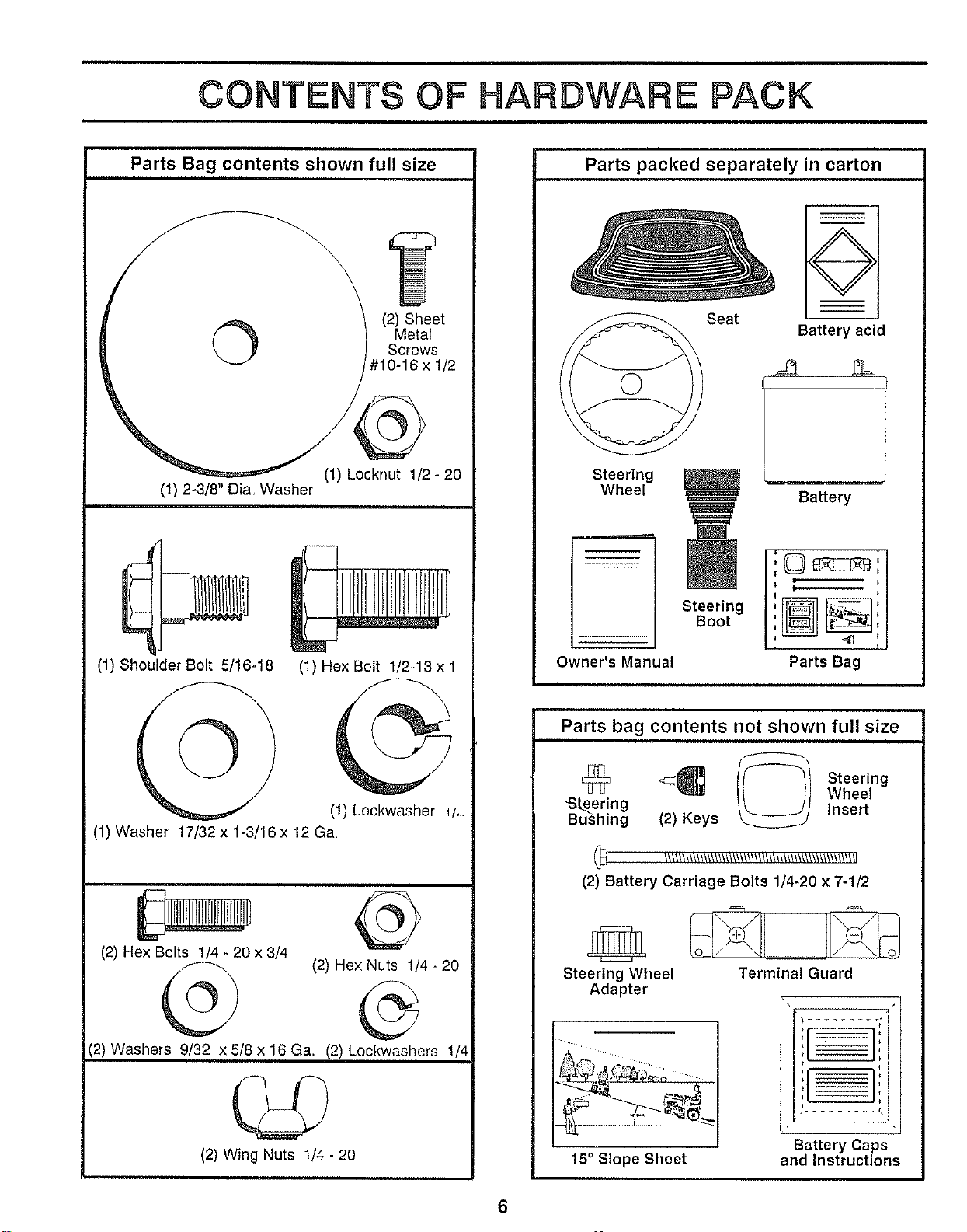
CONTENTS OF ARDWARE PACK
, ,
Parts Bag contents shown full size
©
(2) Sheet
Metal
Screws
#10-16 x 1/2
(1) Locknut 1/2 - 20
(1) 2-3/8" Dia, Washer
(1) Shoulder Bolt 5/16o18
(1) Hex Bolt 1/2-13x 1
(1) Lockwasher 1/-
(1) Washer 17/32 x 1-3/16 x 12 Ga,
(2) Hex Bolts 1/4 - 20 x 3/4
@
(2) Hex Nuts 1/4 - 20
(¢
(2) Washers 9/32 x 5/8 x 16 Ga. (2) Lockwashers 1/4
(2) Wing Nuts 1/4- 20
Parts packed separately in carton
Steering
Wheel
Owner's Manual
Seat
Steering
Boot
Battery acid
Battery
Parts bag contents not shown full size
_q_ <_ _ Steering
Wheel
"Steering Insert
Bushing (2) Keys
(2) Battery Carriage Bolts 1/4-20 x 7-1/2
Steering Wheel
Adapter
Terminal Guard
15° Slope Sheet
!__
t
q
i
-..t,
Battery Caps
and Instructions
6
ASSEMBLY
TOOLS REQUIRED FOR ASSEMBLY
A socket wrench set will make assembly easier Standard
wrench sizes are listed
(1) 5/16" wrench
(2) 7/16" wrenches
(1) 1/2" wrench
(1) 9/16" wrench
(1) 3/4" wrench
Tire pressure gauge
Screwdriver
Utility knife
When right and left hand is mentioned in this manual, it
means when you are in the operating position (seated be-
hind the steering wheel)
TO REMOVE UNIT FROM CARTON
UNPACK CARTON
Remove a!l loose parts from carton (See page 6),
Cut, from top to bottom, all four corners of carton and
lay panels flat
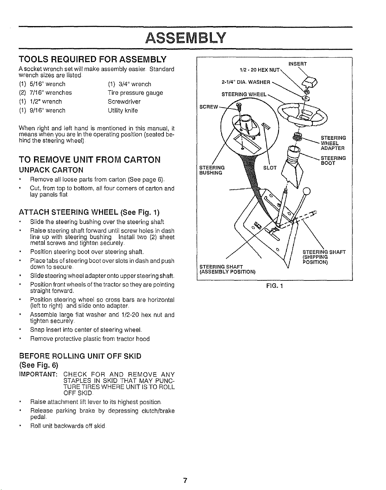
ATTACH STEERING WHEEL (See Fig. 1)
Slide the steering bushing over the steering shaft
Raise steering shaft forward until screw holes in dash
line up with steering bushing Install two (2) sheet
metal screws and tighten securely
Position steering boot over steering shaft,
Place tabs of steering boot over slots in dash and push
down to secure
Slide steering wheel adapter onto upper steering shaft.
Position front wheels of the tractor so they are pointing
straight forward,
Position steering wheel so cross bars are horizontal
(left to right) and slide onto adapter,
Assemble large flat washer and 1/2-20 hex nut and
tighten securely
Snap insert into center of steering wheel.
Remove protective plastic from tractor hood
INSERT
1/
2-1/4" DIA_WASHER
STEERING WHI
STEERING
BUSHING
STEERING
ROOT
STEERING SHAFT
ASSEMBLY POSITION)
STEERING SHAFT
(SHIPPING
POSITION)
FIG. 1
BEFORE ROLLING UNIT OFF SKID
(See Fig. 6)
IMPORTANT: CHECK FOR AND REMOVE ANY
STAPLES IN SKID THAT MAY PUNC-
TURE TIRES WHERE UNIT IS TO ROLL
OFF SKID
Raise attachment lift lever to its highest position
Release parking brake by depressing clutch/brake
pedal,
Roll unit backwards off skid
7
ASSEMBLY
HOW TO SET UP YOUR TRACTOR
PREPARE BATTERY (See Fig. 2)
CAUTION: Wear eye and face shield,
Wash hands or clothing immediately if
accidentally in contactwith battery acid.
Do not smoke. Fumes from charged
battery acid are explosive°
Read the instructions included with the
batteryvent caps. Always wear gloves,
clothing and goggles to protect your
hands, skin and eyes,
Your unit has a battery charging system which is sufficient
for normal use. However, periodic charging of the battery
with an automotive charger will extend its life
See instructions packed with vent caps in parts bag
Fill battery with acid. Fill each cell until it reaches the
bottom of the vent wells. Do not overfill
Allow battery to stand and settle for at least thirty
minutes After standing, check the level of acid If
below the vent wells, add more acid until the correct
level is reached,
While battery is standing (after adding acid) and later, while
battery is being charged, continue with assembly of unit.
To maximize the life of your battery, it is necessary that
the battery be charged before use. Usea 12 volt battery
charger. Charge battery at a rate of 6 amperes for 1
hour, Observe all safety precautions required for bat-
tery charging. Failureto charge battery can result in a
shortened battery life,
Check the acid level after the battery is charged, If the
acid has fallen below the correct level, add distilled or
iron free water,
Install the vent caps to cover the vent wells, Wash fhe
top of the battery with water to remove any acid, then
wipe dry,
Check battery case for leakage to make sure that no
damage has occurred in handling.
Dispose of excess battery acid. Neutralize acid for dis-
posal by adding itto four inches of water in a five gallon
plastic container. Stir with a wooden or plastic paddle
while adding baking soda until the addition of more
soda causes no more foaming
Follow instructions on how to install battery.
CUT AWAY VIEW
I
VENT CAP
L..___J _/,_VENT WELL
_ ATTERY
CELL ACID
LEVEL
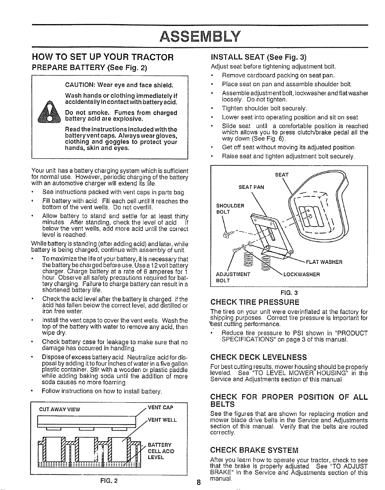
INSTALL SEAT (See Fig. 3)
Adjust seat before tightening adjustment bolt.
Remove cardboard packing on seat pan.
Place seat on pan and assemble shoulder bolt
Assemble adjustment bolt, Iockwasher and flat washer
loosely, Do not tighten.
Tighten shoulder bolt securely.
Lower seat into operating position and sit on seat
Slide seat until a comfortable position is reached
which allows you to press clutch/brake pedal al! the
way down (See Fig, 6).
Get off seat without moving its adjusted position
Raise seat and tighten adjustment bolt securely
SEAT PAN
SHOULDER
BOLT
FLAT WASHER
ADJUSTMENT
BOLT
_LOCKWASHER
FIG, 3
CHECK TIRE PRESSURE
The tires on your unit were overirfflated at the factory for
shipping purposes. Correct tire pressure is important for
_est cutting performance.
Reduce tire pressure to PSI shown in "PRODUCT
SPECIFICATIONS" on page 3 of this manual
CHECK DECK LEVELNESS
For best cutting,_esults, mower housing should be properly
leveled, See TO LEVEL MOWER HOUSING" in the
Service and Adjustments section of this manual
CHECK FOR PROPER POSITION OF ALL
BELTS
See the figures that are shown for replacing motion and
rnower blade drive belts in the Service and Adjustments
section of this manual. Verify that the belts are routed
correctly,
CHECK BRAKE SYSTEM
After you learn how to operate your tractor, check to see
that the brake is properly adjusted, See "TO ADJUST
BRAKE" in the Service and Adjustments section of this
manual
FIG. 2 8
ASSEMBLY
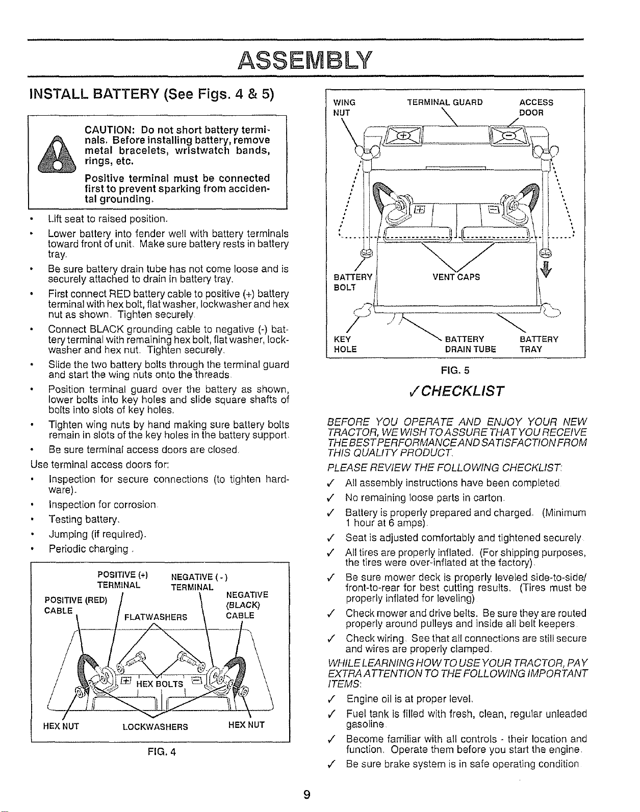
INSTALL BATTERY (:See Figs, 4 & 5)
CAUTION: Do not short battery termi-
nals, Before installing battery, remove
metal bracelets, wristwatch bands,
rings, etc.
Positive terminal must be connected
first to prevent sparking from acciden-
tal grounding,
Lift seat to raised position.
Lower battery into fender well with buttery terminals
toward front of unit, Make sure battery rests in battery
tray
Be sure battery drain tube has not come loose and is
securely attached to drain in battery tray
First connect RED battery cable to positive (+) battery
terminal with hex bolt, flat washer, Iockwasher and hax
nut as shown Tighten securely
Connect BLACK grounding cable to negative (-) bat-
tery terminal with remaining hex bolt, flat washer, lock-
washer and hex nut Tighten securely.
Slide the two battery bolts through the terminal guard
and start the wing nuts onto the threads
Position terminal guard over the battery as shown,
lower bolts into kay holes and slide square shafts of
bolts into slots of kay holes_
Tighten wing nuts by hand making sure battery bolts
remain in slots of the key holes in the battery support
Be sure terminal access doors are closed
Use terminal access doors for:
Inspection for secure connections (to tighten hard-
ware).
Inspection for corrosion
Testing battery.
Jumping (if required).
Periodic charging
POSITIVE (+) NEGATIVE (-)
TERMINAL TERMINAL
NEGATIVE
POSITIVE (RED) (aLACK)
CABLE
FLA'i_VASHERS CABLE
HEX NUT LOCKW'ASHERS HEX NUT
FIG, 4
WING TERMINAL GUARD ACCESS
NUT DOOR
BATTERY
BOLT
KEY
HOLE
"- BATTERY BATTERY
DRAIN TUBE TRAY
FIG. 5
,/'CHECKLIST
BEFORE YOU OPERATE AND ENJOY YOUR NEW
TRACTOR, WE WISH TOASSURE THA T YOU RECEIVE
THEBES TPERFORMANCE AND SATISFAC TION FROM
THIS QUALITY PRODUCT
PLEASE REVIEW THE FOLLOWING CHECKLIST:
,/ All assembly instructions have been completed
v" No remaining loose parts in carton.
v" Battery is properly prepared and charged_ (Minimum
1 hour at 6 amps),
v" Seat is adjusted comfortably and tightened securely
v" All tires are properly inflated, (For shipping purposes.
the tires were over-inflated at the factory),
,I Be sure mower deck is properly leveled side-to-side/
front-to-rear for best cutting results, (Tires must be
properly inflated for leveling)
./ Check mower and drive belts. Besuretheyarerouted
properly around pulleys and inside all belt keepers
,/ Check wiring See that all connections are still secure
and wires are properly clamped,
WHILE LEARNING HOW TO USE YOUR TRACTOR, PAY
EXTRA ATTENTION TO THE FOLLOWING IMPORTANT
ITEMS:
/ Engine oil is at proper level,
€" Fuel tank is filled with fresh, clean, regular unleaded
gasoline
,/ Become familiar with all controls - their location and
function. Operate them before you start the engine
/ Be sure brake system is in safe operating condition
9
OPERATION
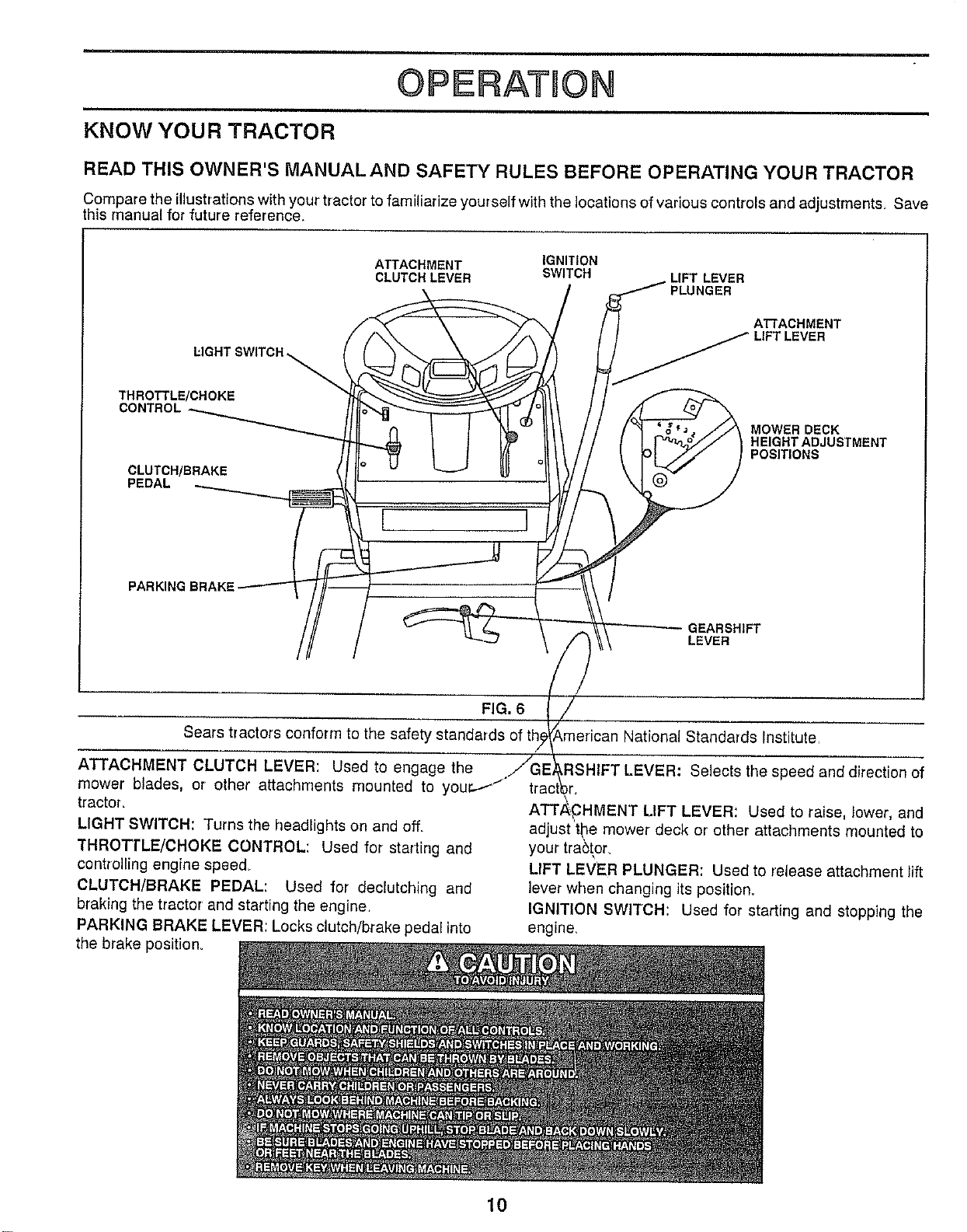
KNOW YOUR TRACTOR
READ THIS OWNER'S MANUALAND SAFETY RULES BEFORE OPERATING YOUR TRACTOR
Compare the illustrations with your tractor to familiarize yourself with the locations of various controls and adjustments. Save
this manual for future reference.
LIGHT SWITCH
THROTTLE/CHOKE
CLUTCH/BRAKE
PEDAL
PARKING BRAKE_
ATTACHMENT IGNITION
CLUTCH LEVER SWITCH
[ ]
LIFT LEVER
PLUNGER
A"(_ACHMENT
LIFT LEVER
MOWER DECK
HEIGHT ADJUSTMENT
POSITIONS
GEARSHIFT
LEVER
FIG. 6
Sears tractors conform to the safety standards of th
titute.
ATTACHMENT CLUTCH LEVER: Used to engage the
mower blades, or other attachments mounted to you
tractor.
LIGHT SWITCH: Turns the headlights on and off.
THROTTLE/CHOKE CONTROL: Used for starting and
controlling engine speed_
CLUTCH/BRAKE PEDAL: Used for declutching and
braking the tractor and starting the engine.
PARKING BRAKE LEVER: Locks clutch/brake pedal into
the brake position.
Selects the speed and direction of
\
ATTP_HMENT LIFT LEVER: Used to raise, lower, and
adjust the mower deck or other attachments mounted to
your tra6tor
LIFT LEVER PLUNGER: Used to release attachment lift
lever when changing its position.
IGNITION SWITCH: Used for starting and stopping the
engine.
10
OPERATUON
i,u
The operation of any tractor can result in foreign ob acts thrown into the eyes, which can
result in severe eye damage. Always wear safety g asses or eye shields while operating
your tractor or performing any ad ustments or repairs We recommend wide vision safety
mask for over the spectacles or standard safety glasses, available at Sears Retail or
Catalog stores.
HOW TO USE YOUR TRACTOR
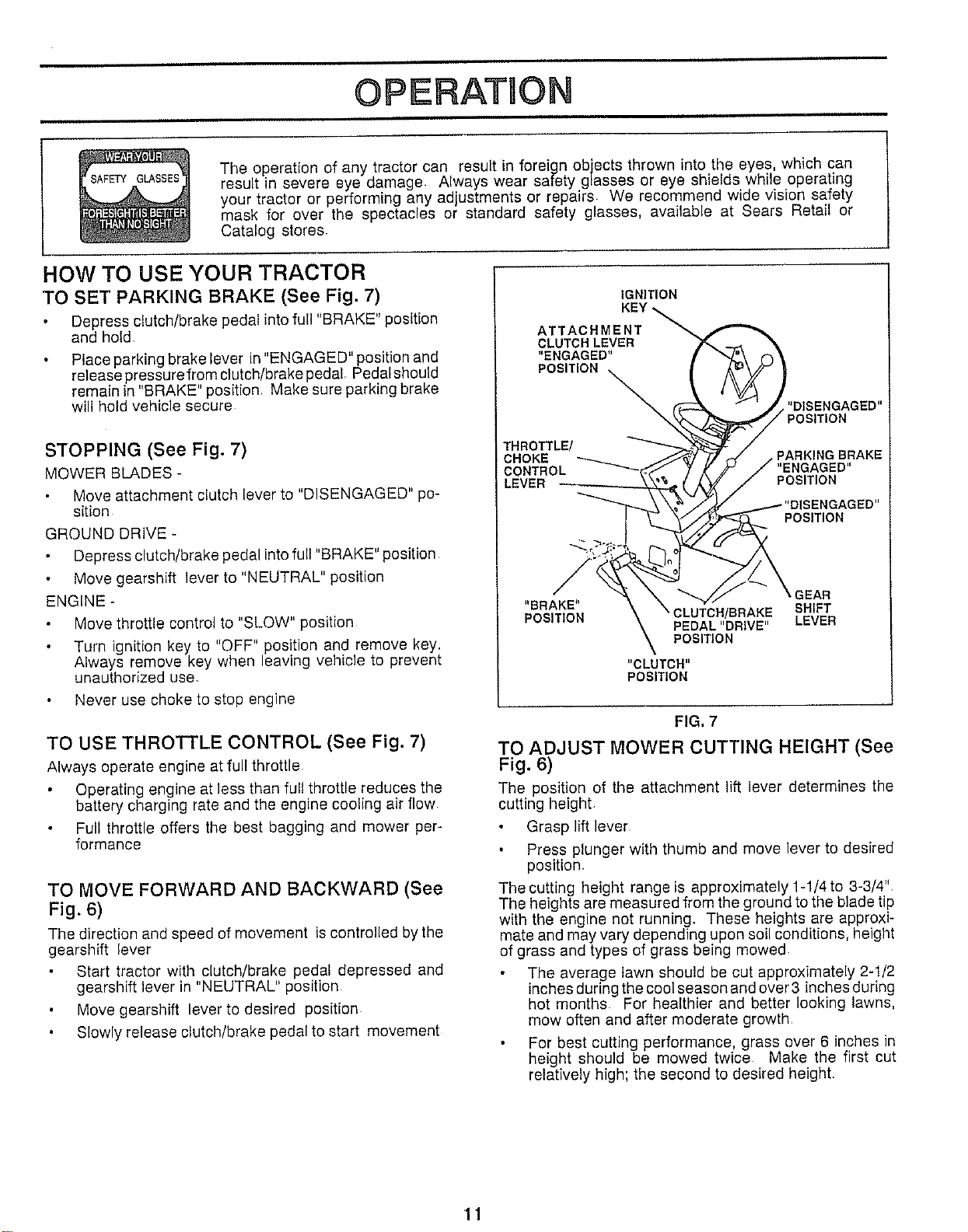
TO SET PARKING BRAKE (See Fig. 7)
Depress clutch/brake pedat into furl "BRAKE" positbn
and hold,
Place parking brake lever in "ENGAGED" position and
release pressure from clutch/brake pedal Pedal should
remain in "BRAKE" position Make sure parking brake
will hold vehicle secure
STOPPING (See Fig. 7)
MOWER BLADES -
Move attachment clutch lever to "DISENGAGED" po-
sition
GROUND DRIVE *
Depress clutch/brake pedal into full "BRAKE" position
Move gearshift lever to "NEUTRAL" position
ENGINE -
Move throttle control to "SLOW" position
Turn ignition key to "OFF" position and remove key.
Always remove key when leaving vehicle to prevent
unautlnorized use,
Never use choke to stop engine
TO USE THROTTLE CONTROL (See Fig. 7)
Atways operate engine at furl throttte
Operating engine at lees than full throttle reduces the
battery charging rate and the engine cooling air flow
Full throttle offers the best bagging and mower per-
formance
TO MOVE FORWARD AND BACKWARD (See
Fig. 6)
The direction and speed of movement is controlled bythe
gearshift lever
Start tractor with clutch/brake pedal depressed and
gearshift lever in "NEUTRAL" position
Move gearshift lever to desired position
Slowly release clutch/brake pedal to start movement
IGNITION
ATTACHMENT
CLUTCH LEVER
"ENGAGED"
POSITION
"DISENGAGED"
POSITION
THROTTL_
CHOKE BRAKE
CONTROL "ENGAGED"
LEVER POSITION
POSITION
_EAR
"BRAKE" SHIFT
POSITION PEDAL "DRIVE" LEVER
POSITION
"CLUTCH"
POSITION
FIG. 7
TO ADJUST MOWER CUTTING HEIGHT (See
Fig. 6)
The position of the attachment lift lever determines the
cutting height,
Grasp lift lever
Press plunger with thumb and move lever to desired
position.
The cutting height range is approximately 1-1/4 to 3-3/4'L
The heights are measured from the ground to the blade tip
with the engine not running. These heights are approxi-
mate and may vary depending upon soil conditions, height
of grass and types of grass being mowed
The average lawn should be cut approximately 2-1/2
inches during the cool season and over 3 inches during
hot months. For healthier and better looking lawns,
mow often and after moderate growth_
For best cutting performance, grass over 6 inches in
height should be mowed twice Make the first cut
relatively high; the second to desired height.
OPERATmON
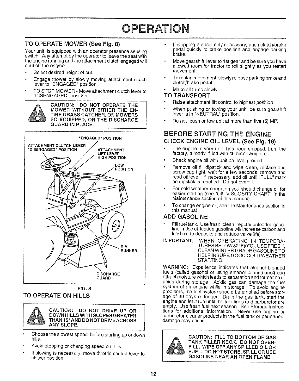
TO OPERATE MOWER (See Fig. 8)
Your unit is equipped with an operator presence sensing
switch Any attempt by the operator to leave the seat with
the engine running and the attachment clutch engaged will
shut off the engine
Select desired height of cut
Engage mower by slowly moving attachment clutch
lever to "ENGAGED" position
TO STOP MOWER - Move attachment clutch lever to
"DISENGAGED" position
CAUTION: DO NOT OPERATE THE
MOWER WITHOUT EITHER THE EN-
TIRE GRASS CATCHER, ON MOWERS
SO EQUIPPED, OR THE DISCHARGE
GUARD IN PLACE.
"ENGAGED" POSITION
ATTACHMENT CLUTCH LEVER
"DISENGAGED" POSITION ATTACHMENT
HIGH POSITION
LOW
a,H_
RUNNER
DISCHARGE
GUARD
FIG, 8
TO OPERATE ON HILLS
CAUTION: DO NOT DRIVE UP OR
DOWN HILLS WITH SLOPES GREATER
THAN 15°AND DO NOT DRIVEACROSS
ANY SLOPE.
Choose the slowest speed before starting up or down
hills
Avoid stopping or changing speed on hills
If slowing is neces£_ j, move throttle control lever to
slower' position
If stopping is absolutely necessary, push clutch/brake
pedal quickly to brake position and engage parking
brake.
Move gearshift lever to 1st gear and be sure you have
allowed room for' tractor to roll slightly as you restart
movement.
To restart movement, slowly release parking brake and
clutch/brake pedal,
Make all turns slowly
TO TRANSPORT
Raise attachment lift control to highest position
When pushing or towing your unit, be sure gearshift
lever is in "NEUTRAL" position.
Do not push or tow unit at more than five (5) MPH
BEFORE STARTING THE ENGINE
CHECK ENGINE OIL LEVEL (See Fig. 16)
The engine in your unit has been shipped, from the
factory, already filled with summer weight oil.
Check engine oil with unit on level ground
Remove oil fill dipstick and wipe clean, replace and
screw cap tight, wait for a few seconds, remove and
read oil level If necessary, add oil until "FULL" mark
on dipstick is reached Do not overfill
For cold weather operation you should change oil for
easier' starting (see "OIL VISCOSITY CHART" in the
Maintenance section of this manual)
To change engine oil, see the Maintenance section in
this manual
ADD GASOLINE
Fill fuel tank. Use fresh, clean, regular unleaded gaso-
line. (Use of leaded gasoline will increase carbon and
lead oxide deposits and reduce valve life)
IMPORTANT: WHEN OPERATING IN TEMPERA-
TURES BELOW32°F(0°C), USE FRESH,
CLEAN WINTER GRADE GASOLINE TO
HELP INSURE GOOD COLD WEATHER
STARTING
WARNING: Experience indicates that alcohol blended
fuels (called gasohol or using ethanol or methanol) carl
attract moisture which leads to separation and formation of
acids during storage Acidic gas can damage the fuel
system of an engine while in storage To avoid engine
problems, the fuel system should be emptied before stor-
age of 30 days or longer. Drain the gas tank, start the
engine and let it run until the fuel lines and carburetor are
empty. Use fresh fuel next season See Storage Instruc-
tions for additional information Never' use engine or
carburetor cleaner products in the fuel tank or permanent
damage may occur
CAUTION: FILL TO BOTTOM OF GAS
TANK FILLER NECK. DO NOT OVER-
FILL. WIPE OFF ANY SPILLED OIL OR
FUEL. DO NOTSTORE, SPILLOR USE
GASOLINE NEAR AN OPEN FLAME.
12
_-ii i
OPERATION
3"0 START ENGINE (See Fig. 7)
When starting engine for the first time or if engine has
run out of fuel, it will take extra cranking time to move
fuel from the tank to the engine
Depress the clutch/brake pedal and set the parking
brake
Place gearshift lever in "NEUTRAL" position
Move attachment clutch to "DISENGAGED" position
Move throttle control lever to "CHOKE" position for
cold engine start For warm engine start, move
throttle control to "FAST" position
Turn ignition key clockwise to "START" position and
release key as soon as engine starts. Do not run
starter continuously for more than fifteen seconds
per minute If engine does not start af!er several
attempts, move throttle control to "FAST' position,
wait a few minutes and try again
When engine starts, move throttle control to desired
position
Allow engine to warm up for a few minutes before
engaging drive or attachment clutch
NOTE; If at a high altitude (above 3000 feet) or in cold
temperatures (below 32 ° F), the carburetor fuel mixture
may need to be adjusted for best engine performance.
"TO
See ADJUST CARBURETOR" in the Service and
Adjustments section of this manual
MOWING TIPS
Tire chains cannot be used when the mower hous-
ing is attached to unit
Mower should be properly leveled for best mowing
performance. See TO LEVEL MOWER HOUSING
m the Service and Adjustments section of this
manual
Use the runner on the right hand side of mower as
a guide. The blade cuts approximately an inch
outside the runner (See Fig 8)
The left hand side of mower should be used for trim-
ming
Drive so that clippings are disci_arged onto the area
that has been cut Have the cut area to [he right of
the machine. This will result in a more even distri-
bution of clippings and more uniform cutting
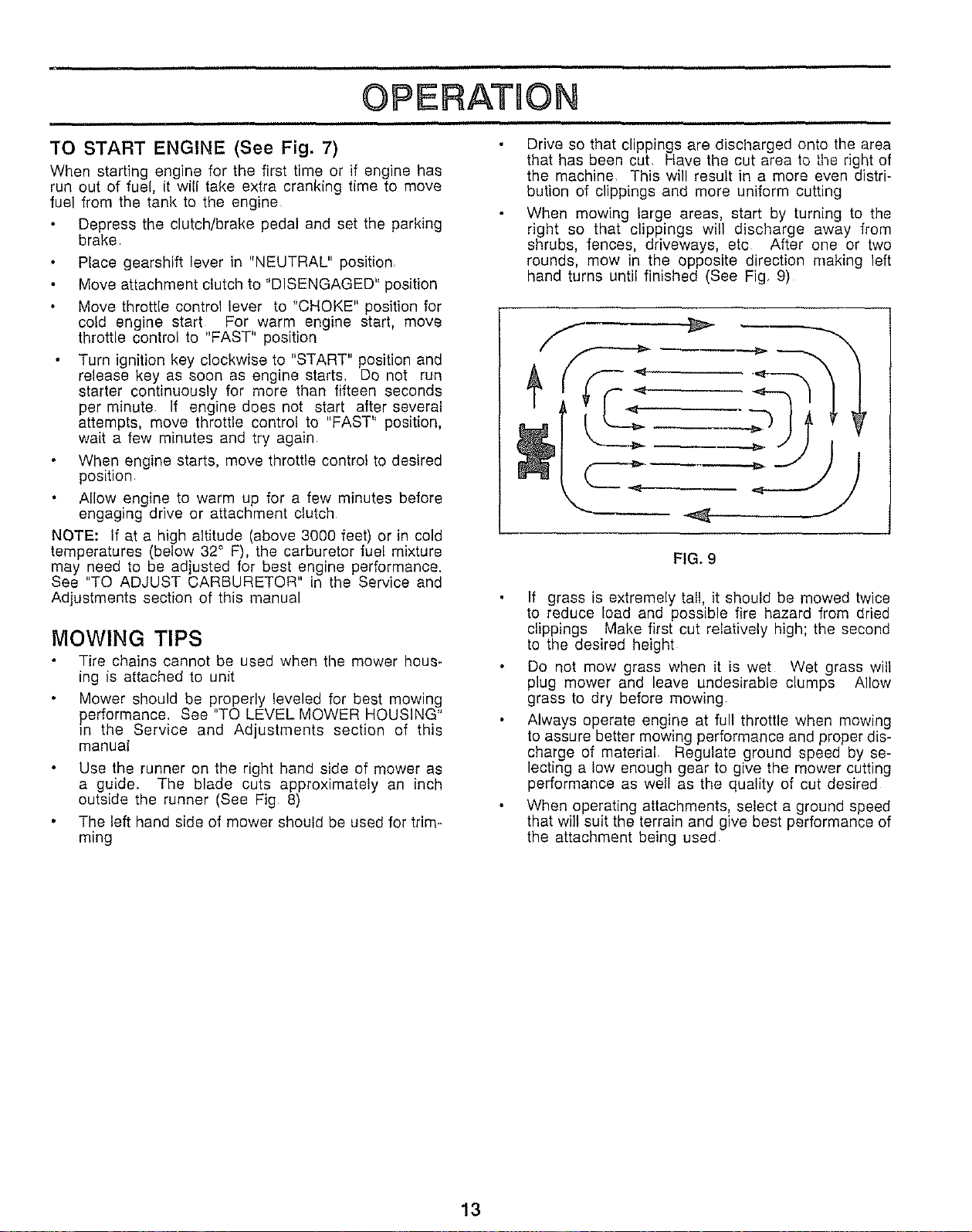
When mowing large areas, start by turning to the
right so that clippings will discharge away from
shrubs, fences, driveways, etc After one or two
rounds, mow in the opposite direction making left
hand turns until finished (See Fig. 9)
FIG. 9
If grass is extremely tall, it should be mowed twice
to reduce load and possible fire hazard from dried
clippings Make first cut relatively high; time second
to the desired height
Do not mow grass when it is wet Wet grass will
plug mower and leave undesirable clumps Allow
grass to dry before mowing
Always operate engine at full throttle when mowing
to assure better mowing performance and proper dis-
charge of material Regulate ground speed by se-
lecting a low enough gear to give the mower cutting
performance as well as the quality of cut desired
When operating attachments, select a ground speed
that will suit the terrain and give best performance of
the attachment being used
13
MAHNTENANCE
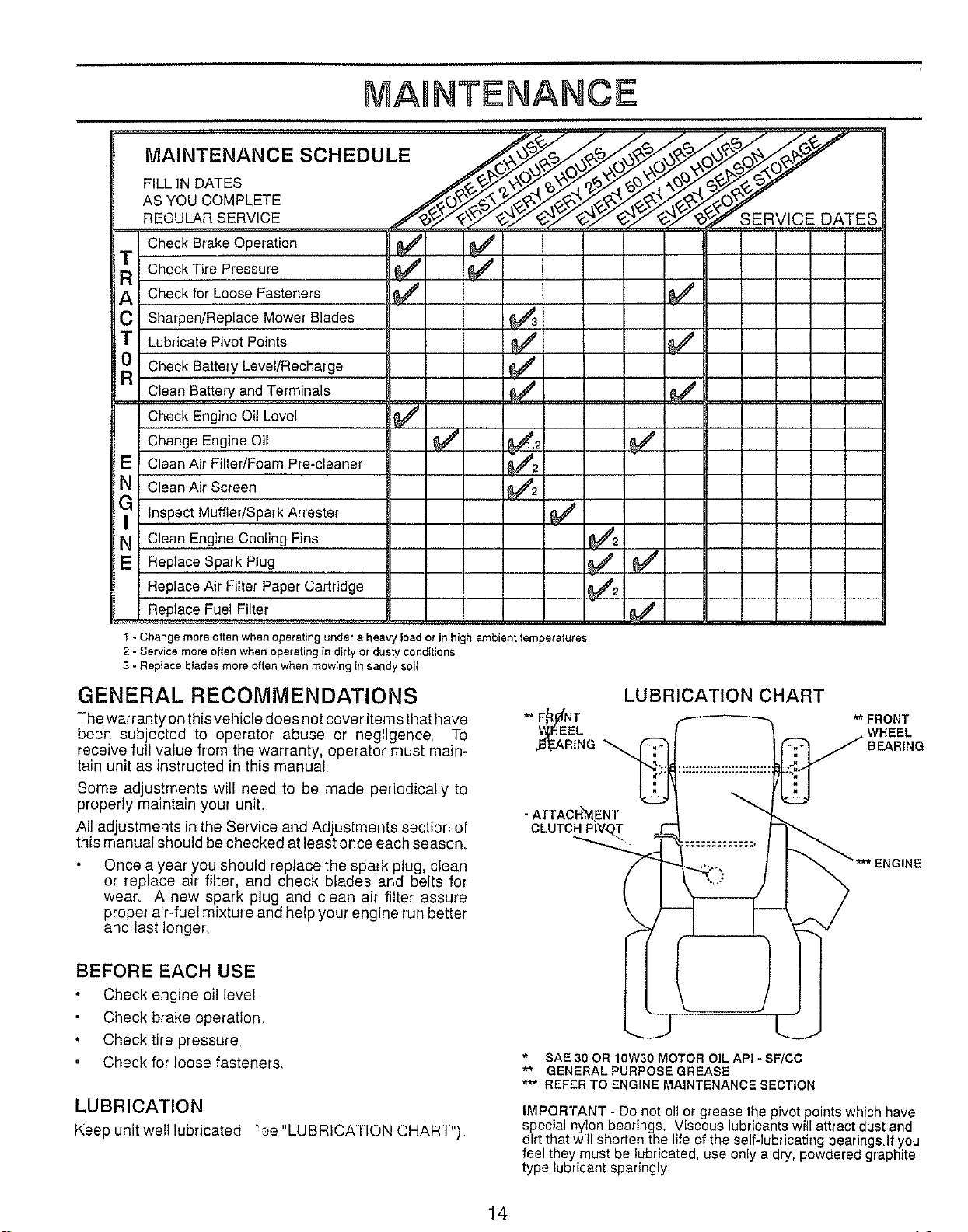
Check Tire Pressure 6/ 6/
A Check for Loose Fasteners _4' _'
C Sharpen/Replace Mower Blades
T Lubricate Pivot Points 6/ 6/
Check Battery Level/Recharge 6/
Clean Battery and Terminals 6/
Check Engine Oil Level 6/
Change Engine Oil 6/ _.2 6/
E Clean Air Filter/Foam Pre-cleaner _2
N CleanAir Screen 6/2
G Inspect Muffler/Spark Arrester 6/
N Clean Engine Cooling Fins 6/2
Replace Spark Plug 6/ 6/
Replace Air Filter Paper Cartridge 6/2
Replace Fuel Filter
, ,,,.... ,,, , ................
AS YOU COMPLETE _O£:_ _ t.,_ _ _._j_ _.¢ _ ;_)_:_
REGULAR SERVICE .... /__"_O_E F:IVIC E D/_T ES
Check B;ake Operation 6/ 6/
1 - Change more often when operating under a heaW load or in high ambient temperatures
2 - Service more often when operating in dirty or dusty conditions
3 - Replace blades more often when mowing in sandy soil
GENERAL RECOMMENDATIONS
The wafranty on this vehicle does not cover items that have
been subjected to operator abuse or negligence To
receive full value from the warranty, operator must main-
tain unit as instructed in this manual,
Some adjustments will need to be made periodically to
properly maintain your uniL
All adjustments in the Service and Adjustments section of
this manual should be checked at least once each season,
Once a year you should replace the spark plug, clean
or replace air filter, and check blades and belts for
wear. A new spark plug and clean air filter assure
proper air-fuel mixture and help your engine run better
andlast longer
LUBRICATION CHART
,.B_RING
- ATTAC H_YI,ENT
CLUTC_
FRONT
WHEEL
BEFORE EACH USE
Check engine oil level
Check blake operation
Check tire pressure
Check for loose fastener&
LUBRICATION
Keep unit welt lubricated
"'.._e"LUBRICATION CHART").
* SAE 30 OR lOW30 MOTOR OIL API - SF/CC
GENERAL PURPOSE GREASE
*** REFER TO ENGINE MAINTENANCE SECTION
IMPORTANT - Do not oil or grease the pivot points which have
special nylon bearings. Viscous lubricants will attract dust and
dirt that will shorten the life of the selfqubricating bearings.If you
feel they must be lubricated, use only a dry, powdered graphite
type lubricant sparingly.
14
MAINTENANCE
TRACTOR
Always observe safety rules when ?er[orming any mainte-
nance
TIRES
Maintain proper air pressure in all tires (See "PROD-
UCT SPECIFICATIONS" on page 3 of this manual).
Keep tires free of gasoline, oil, or insect control chemi-
cals which can harm rubber
Avoid stumps, stones, deep ruts, sharp objects and
other hazards that may cause tire damage.
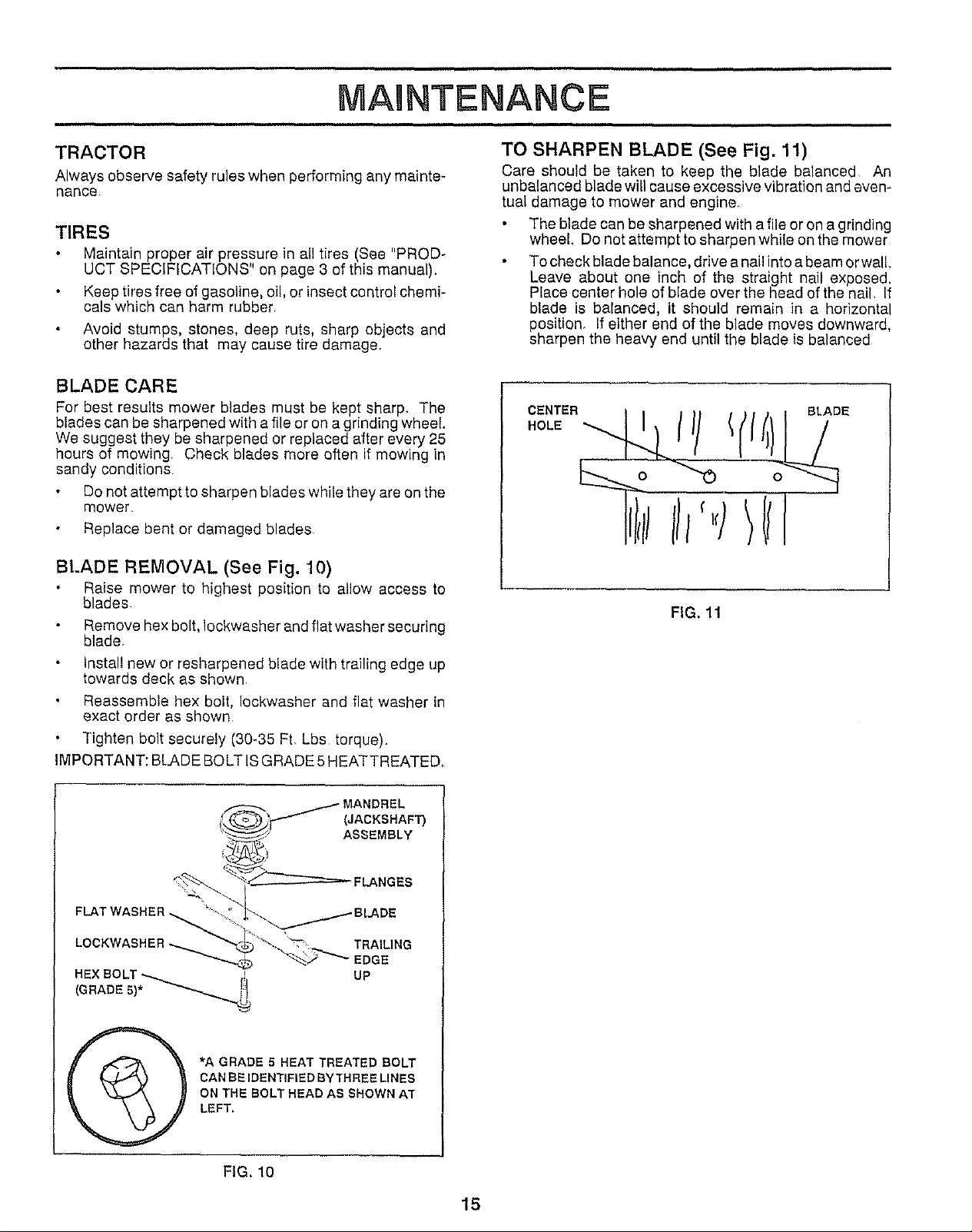
TO SHARPEN BLADE (See Fig. 11)
Care should be taken to keep the blade balanced An
unbalanced blade will cause excessive vibration and even-
tual damage to mower and engine
The blade can be sharpened with a file or on a grinding
wheel Do not attempt to sharpen while on the mower
To check blade balance, drive a nail into a beam or wall
Leave about one inch of the straight nail exposed,
Place center hole of blade over the head of the nail, If
blade is balanced, it should remain in a horizontal
position. If either end of the blade moves downward,
sharpen the heavy end until the blade is balanced
BLADE CARE
For best results mower blades must be kept sharp, The
blades can be sharpened with a file or on a grinding wheel.
We suggest they be sharpened or replaced after every 25
hours of mowing. Check blades more often if mowing in
sandy conditions
Do not attempt to sharpen blades while they are on the
mower,
Replace bent or damaged blades.
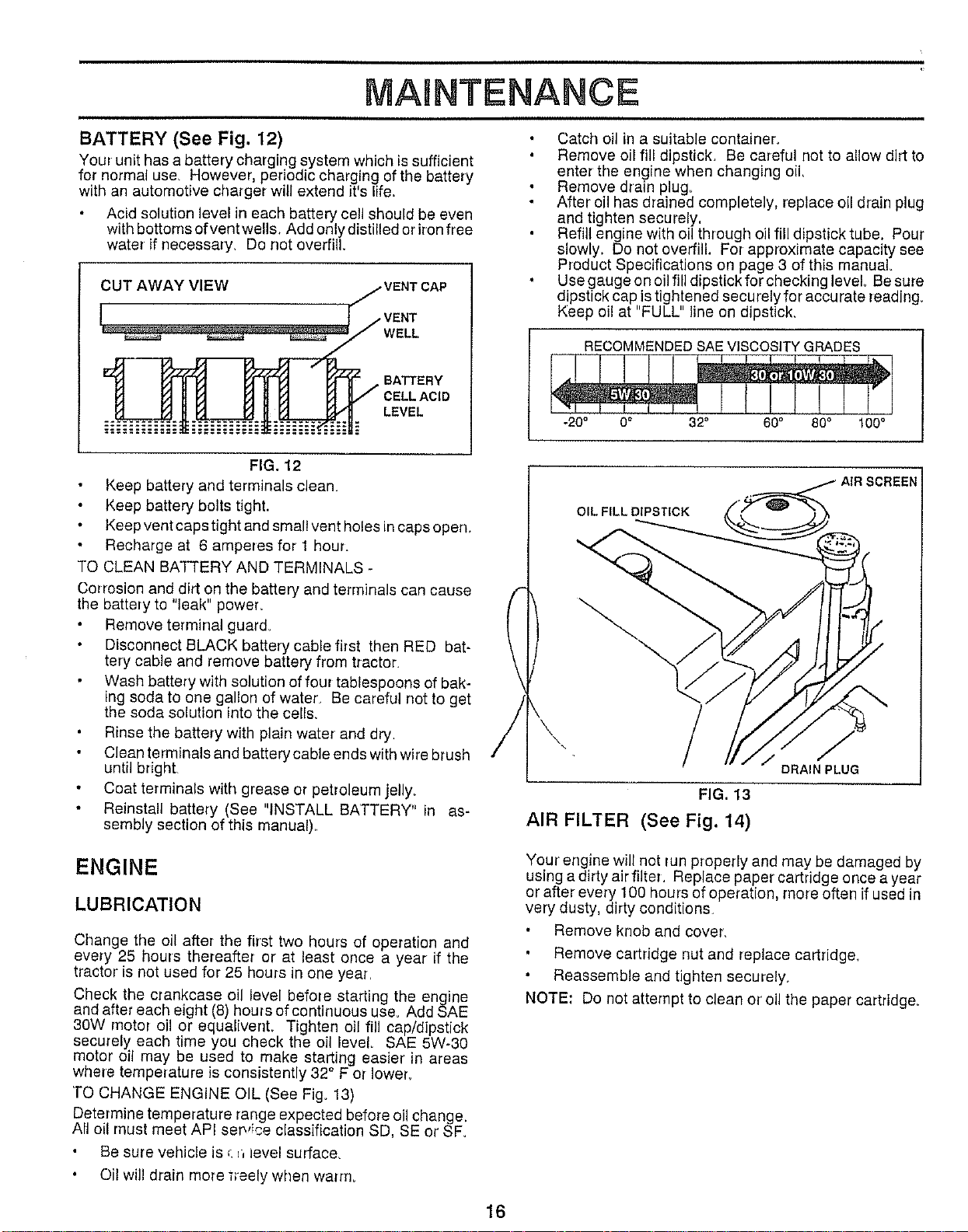
BLADE REMOVAL (See Fig. 10)
Raise mower to highest position te allow access to
blades
Remove hex bolt, Iockwasher and flat washer securing
blader
install new or resharpened blade with trailing edge up
towards deck as shown,
Reassemble hex bolt, Iockwasher and flat washer in
exact order as shown
Tighten bolt securely (30-35 Ft. Lbs torque).
IMPORTANT: BLADE BOLT ISGRADE 5 HEATTREATED.
CENTER
HOLE
FIG. 11
/ MANDREL
i!___._..,_l _-'_- (JACKSHAFT)
L_) ASSEMBLY
"_>_ "_---_ FLANGES
FLAT WASHER _' _GLADE
LOCKWASHER _ _'-L_ _-,,' _, _. TRAILING
EDGE
HEX BOLT _- _ UP
(GRADE 5)* __,
*A GRADE 5 HEAT TREATED BOLT
CAN BE IDENTIFIED BY TH REE LINES
ON THE BOLT HEAD AS SHOWN AT
LEFT,
FIG. 10
15
NTENANCE
BATTERY (See Fig. 12)
Your unit has a battery charging system which is sufficient
for normal use, However, periodic charging of the battery
with an automotive charger will extend it's life.
Acid solution level in each battery ceil should be even
with bottoms ofvent wells, Add only distilled or iron free
water if necessary, Do not overfill.
CUT AWAY VIEW /VENT CAP
"--IA V_-Ir_ VF'I_ K,""_ BATTERY
L,V,L
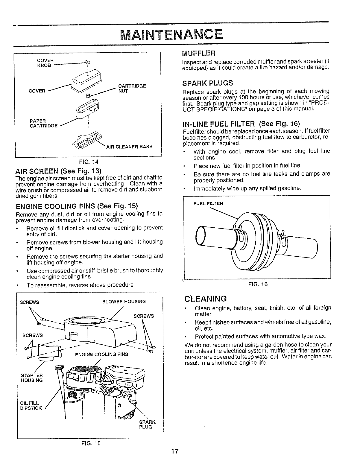
Catch oil in a suitable container,
Remove oil fill dipstick, Be careful not to allow dirt to
enter the engine when changing oil,
Remove drain plug.
After oil has drained completely, replace oil drain plug
and tighten securely,
Refill engine with oil through oil fill dipstick tube. Pour
slowly. Do not overfill. For approximate capacity see
Product Specifications on page 3 of this manual.
Use gauge on oil fill dipstick for checking level, Be sure
dipstick cap is tightened securely for accurate reading.
Keep oil at "FULL" line on dipstick,
RECOMMENDEDSAE VISCOSITYGRADES
! I[- '
.20° 0o 32° 60° 80° 100°
FIG. 12
Keep battery and terminals clean.
Keep battery bolts tight.
Keep vent caps tight and small vent holes in caps open.
Recharge at 6 amperes for 1 hour.
TO CLEAN BATTERY AND TERMINALS -
Corrosion and dirt on the battery and terminals can cause
the battery to "leak" power.
Remove terminal guard.
Disconnect BLACK battery cable first then RED bat-
tery cable and remove battery from tractor,
Wash battery with solution of four tablespoons of bak-
ing soda to one gallon of water, Be careful not to get
the soda solution into the cells,
Rinse the battery with plain water' and dry.
Clean terminals and battery cable ends with wire brush
until bright
Coat terminals with grease or petroleum jelly,
Reinstall battery (See "INSTALL BATTERY" in as-
sembly section of this manual).
OIL FILL DIPSTICK
,. /
FIG. 13
AIR FILTER (See Fig. 14)
/
DRAIN PLUG
ENGINE
LUBRICATION
Change the oil after the first two hours of operation and
every 25 houls thereafter or at least once a year if the
tractor is not used for 25 hours in one year,
Check the crankcase oil level before starting the engine
and after each eight (8) hours of continuous use. Add SAE
30W motor oil or equalivent. Tighten oil fill cap/dipstick
securely each time you check the oil level. SAE 5W-30
motor oil may be used to make starting easier' in areas
where temperature is consistently 32 ° F ot lower,
TO CHANGE ENGINE OIL (See Fig. 13)
Determine temperature range expected before oil change,
All oil must meet API ser_,ice classification SD, SE or SF.
Be sure vehicle is _n level surface,
Oil will drain more ;reely when warm.
Your engine will not run properly and may be damaged by
using a dirty air filter, Replace paper cartridge once a year
or after every 100 hours of operation, more often if used in
very dusty, dirty conditions,
Remove knob and cover,
Remove cartridge nut and replace cartridge,
Reassemble and tighten securely,
NOTE: Do not attempt to clean or' oil the paper cartridge,
16
NTENANCE
COVER
KNOB _-'_-----'_
COVER
CARTRIDGE
NUT
PAPER
CARTRIDGE
CLEANER BASE
FIG. 14
AIR SCREEN (See Fig. 13)
The engine air screen must be kept free of dirt and chaff to
prevent engine damage from overheating, Clean with a
wire brush or compressed air to remove dirt and stubborn
dried gum fibers,
ENGINE COOLING FINS (See Fig. 15)
Remove any dust, dirt or oil from engine cooling fins to
prevent engine damage from overheating
Remove oil fill dipstick and cover opening to prevent
entry of dirt
Remove screws from blower housing and lifthousing
off engine.
Remove the screws securing the starter housing and
lift housing off engine.
Use compressed air or stiff bristle brush to thoroughly
clean engine cooling fins
To reassemble, reverse above procedure.
SCREWS BLOWER HOUSING
SCREWS
SCREWS
STARTER
HOUSING
ENGINE COOLING FINS
OIL FILL
DIPSTICK
SPARK
PLUG
MUFFLER
Inspect and replace corroded muffler and spark arrester (if
equipped) as it could create a fire hazard and/or damage.
SPARK PLUGS
Replace spark plugs at the beginning of each mowing
season or after every 100 hours of use, whichever comes
first. Spark plug type and gap setting is shown in "PROD-
UCT SPECIFICATIONS" on page 3 of this manual
IN-LINE FUEL FILTER (See Fig. 16)
Fuel filter should be replaced once each season. Iffuel filter
becomes clogged, obstructing fuel flow to carburetor, re-
placement is required
With engine cool, remove filter and plug fuel line
sections.
Place new fuel filter in position in fuel line.
Be sure there are no fuel line leaks and clamps are
properly positioned.
Immediately wipe up any spilled gasoline.
FIG, 16
CLEANING
Clean engine, battery, seat, finish, etc of all foreign
matter.
Keep finished surfaces and wheels free of all gasoline,
oil, etc.
Protect painted surfaces with automotive type wax.
We do not recommend using a garden hose to clean your
unit unless the electrical system, muffler, air filter and car-
buretor are covered to keep water out. Water in engine can
result in a shortened engine life_
FIG. 15
17
ERV CE AN ADJUSTMENTS
&
CAUTION: BEFORE PERFORMING ANY SERVICE OR ADJUSTMENTS:
Depress clutch/brake pedal fully and set parking brake.
Place gearshift lever in "NEUTRAL" position.
Place attachment clutch in "DISENGAGED" position.
Turn ignition key "OFF" and remove key,
Make sure the blades and all moving parts have completely stopped.
Disconnect spark plug wire from spark plug and place wire where it cannot come in contact with
plug,
TRACTOR
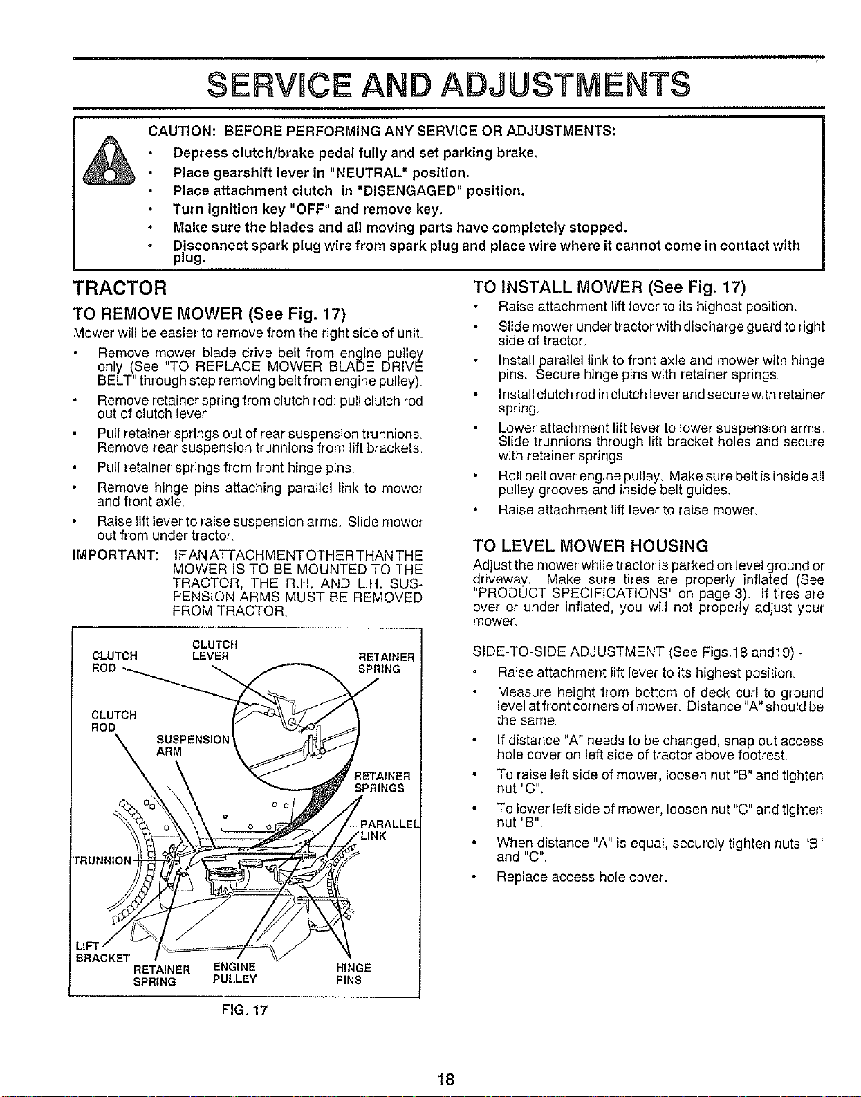
TO REMOVE MOWER (See Fig. 17)
Mower will be easier to remove from the right side of uniL
Remove m,ower blade drive belt from engine pulley
only (See TO REPLACE MOWER BLADE DRIVE
BELT" through step removing belt from engine pulley),
Remove retainer spring from clutch rod; pull clutch red
out of clutch lever
Pull retainer springs out of rear suspension trunnions,
Remove rear suspension trunnions from lift brackets,
Pull retainer springs from front hinge pins,
Remove hinge pins attaching parallel link to mower
and front axle,
Raise lift lever to raise suspension arms, Slide mower
out from under tractor,
IMPORTANT: IFAN ATTACHMENT OTHER THAN THE
MOWER IS TO BE MOUNTED TO THE
TRACTOR, THE R.H, AND L.H. SUS-
PENSION ARMS MUST BE REMOVED
FROM TRACTOR,
TO INSTALL MOWER (See Fig. 17)
Raise attachment lift lever to its highest position,
Slide mower under tractor with discharge guard to right
side of tractor,
Installparallel link to front axle and mower with hinge
pins, Secure hinge pins with retainer springs,
Install clutch rodin clutch lever and secure with retainer
spring,
Lower' attachment lift lever to lower suspension arms,
Slide trunnions through lift bracket holes and secure
with retainer springs
Roll belt over engine pulley. Make sure belt is inside all
pulley grooves and inside belt guides.
Raise attachment lift lever to raise mower,
TO LEVEL MOWER HOUSING
Adjust the mower while tractor is parked on level ground or'
driveway, Make sure tires are properly inflated (See
"PRODUCT SPECIFICATIONS" on page 3). If tires are
over or under inflated, you will not propedy adjust your
mower,
CLUTCH
CLUTCH LEVER
ROD
CLUTCH
ROD
rRUNNIOI _
LIFT
BRACKET
RETAINER ENGINE
SPRING PULLEY
RETAINER
SPRING
RETAINER
SPRINGS
!
- PARALLEL
/LINK
HINGE
PINS
SIDE-TO-SiDE ADJUSTMENT (See Figs,18 and19) -
Raise attachment lift lever to its highest position,
Measure height from bottom of deck curl to ground
level at front cot nets of mower_ Distance "A" should be
the same
If distance "A" needs to be changed, snap out access
hole cover on left side of tractor above footrest,
To raise left side of mower, loosen nut "B" and tighten
nut "C",
To lower left side of mower, loosen nut "C" and tighten
nut "B"
When distance "A" is equal, securely tighten nuts "B"
and "C",
Replace access hole cover.
FIGo 17
18
$ERVRCE AND AOJUSTNIENT$
REAR SUSPENSION ARM
LIFT LEVER
RAISED _
POS T ON)
BOTTOM
OF CURL
I
\
GROUND LINE
BOTTOM
OF CURL
LA
FIG. 18
FIG, 19
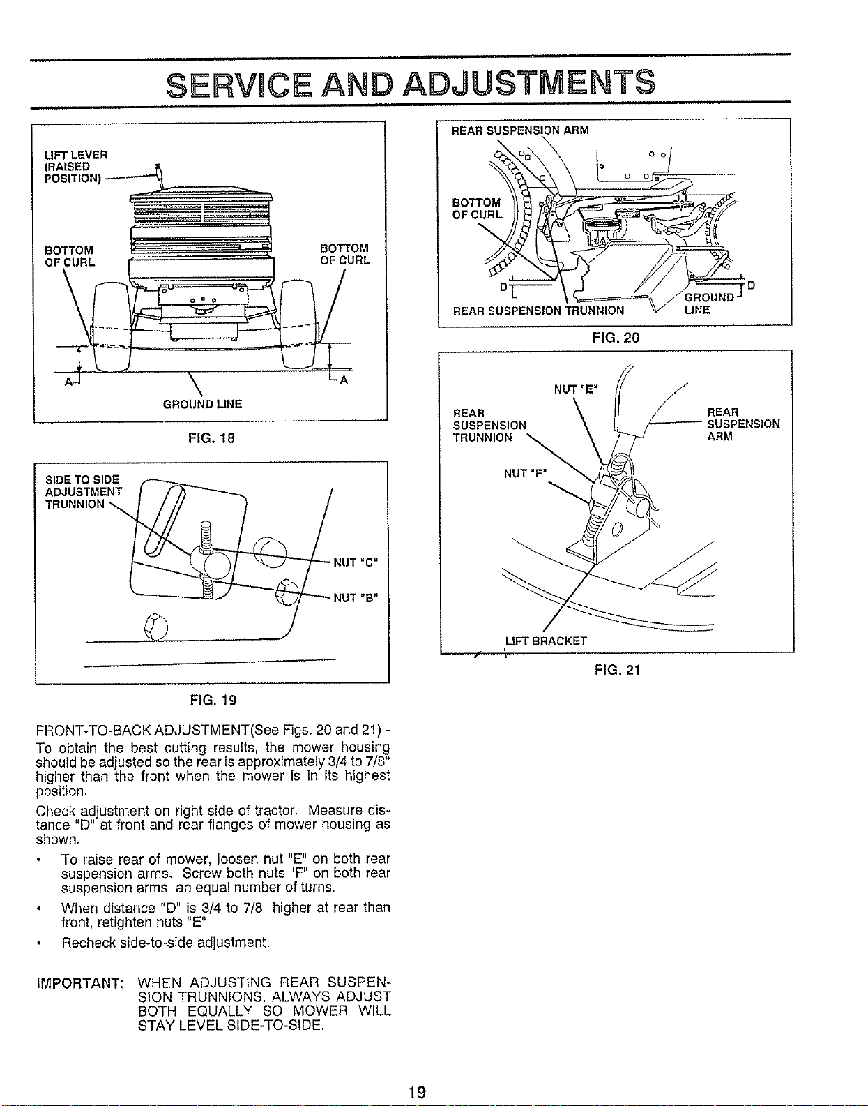
FRONT-TO-BACK ADJUSTMENT(See Figs. 20 and 21) -
To obtain the best cutting results, the mower housing
should be adjusted so the rear isapproximately 3/4 to 7/8"
higher than the front when the mower is in its highest
position.
Check ad ustment on right side of tractor. Measure dis-
tance D at front and rear fanges of mower housing as
shown.
To raise rear of mower, loosen nut "E" on both rear
suspension arms. Screw both nuts "F" on both rear
suspension arms an equal number of turns.
When distance "D" is 3/4 to 7/8" higher at rear than
front, retighten nuts "E".
Recheck side-to-side adjustment.
BOTTOM
OF CURL
BT-
REAR SUSPENSION TRUNNION
-_F D
IROUND
LINE
FIG, 20
REAR
SUSPENSION
TRUNNIOIuT,,F._
REAR
SUSPENSION
ARM
LIFT BRACKET
FIG. 21
IMPORTANT: WHEN ADJUSTING REAR SUSPEN-
SION TRUNNIONS, ALWAYS ADJUST
BOTH EQUALLY SO MOWER WILL
STAY LEVEL SIDE-TO-SIDE_
19
i.111
SERVICE AND ADJUSTMENTS
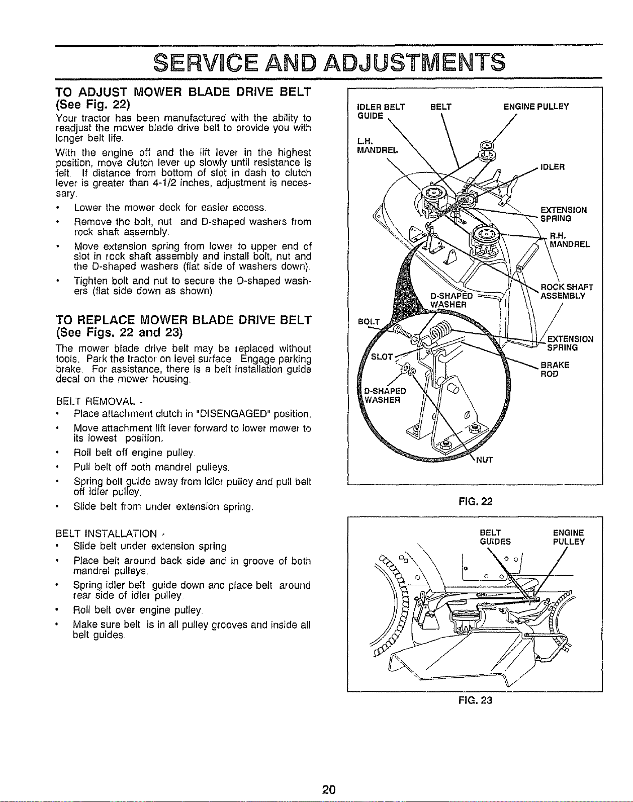
TO ADJUST MOWER BLADE DRIVE BELT
(See Fig. 22)
Your tractor has been manufactured with the ablity to
read ust the mower blade drive belt to provide you with
onger bet fe.
With the engine off and the lift lever in the highest
position, move clutch lever up slowly until resistance is
felt If distance from bottom of slot in dash to clutch
lever is greater than 4-1/2 inches, adjustment is neces-
sary
Lower the mower deck for easier access.
Remove the bolt, nut and D-shaped washers from
rock shaft assembly
Move extension spring from lower to upper end of
slot in rock shaft assembly and install bolt, nut and
the D-shaped washers (fiat side of washers down)
Tighten bolt and nut to secure the D-shaped wash-
ers (fiat side down as shown)
TO REPLACE MOWER BLADE DRIVE BELT
(See Figs. 22 and 23)
The mower blade drive belt may be replaced without
tools. Park the tractor on level surface Engage parking
brake For assistance, there is a belt instalation guide
decal on the mower housing
BELT REMOVAL -
Place attachment clutch in "DISENGAGED" position.
Move attachment lift lever forward to lower mower to
its lowest position.
Roll belt off engine puley
Pull belt off both mandrel pulleys.
Spring belt guide away from idler pulley and pull belt
off idler pulley.
Slide belt from under extension spring.
IDLER BELT BELT ENGINE PULLEY
GUIDE \ /
MANDR
J'°'°°
/
/!I\ _ _ EXTENSION
IOLT INS ON
f, L_ SP.,NG
o-s= Eo
FIG, 22
BELT INSTALLATION -
Slide belt under extension spring
Place belt around back side and in groove of both
mandrel pulleys
Spring idler belt guide down and place belt around
rear side of idler pulley
Roll belt over engine pulley
Make sure belt is in all pulley grooves and inside all
belt guides.
BELT
GUIDES
ENGINE
PULLEY
FIG. 23
2O
ERVJCE AND ADJUSTMENTS
,,,,r, , ,,
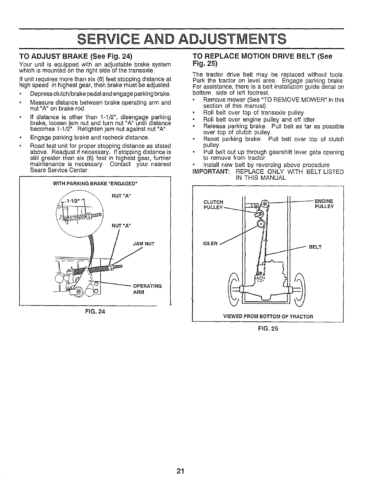
TO ADJUST BRAKE (See Fig. 24)
Your unit is equipped with an adjustable brake system
which is mounted on the right side of the transaxle
If unit requires more than six (6) feet stopping distance at
high speed in highest gear, then brake must be adjusted,
Depress clutch/brake pedal and engage parking brake,
Measure distance between brake operating arm and
nut "A" on brake rod
If distance is other than 1-1/2". disengage parking
brake, loosen jam nut and turn nut "A" until distance
becomes 1-1J2" Retighten jam nut against nut "A"_
Engage parking brake and recheck distance,
Road test unit for proper stopping distance as stated
above, Read ust if necessary. If stopping distance is
sti greater than sx (6) feet n highest gear, further
maintenance is necessary, Contact your nearest
Sears Service Center,
WITH PARKING BRAKE "ENGAGED"
NUT=A"
NUT"A"
_ JAM NUT
OPERATI"G
ARM
FIG. 24
TO REPLACE MOTION DRIVE BELT (See
Fig. 25)
The tractor drive belt may be replaced without tools,
Park the tractor on level area, Engage parking brake
For assistance, there is a belt installation guide decal on
bottom side of left footrest.
Remove mower (See "TO REMOVE MOWER" in this
section of this manual),
Roll belt over top of transaxle pulley
Roll belt over engine pulley and off idler,
Release parking brake, Pull belt as far as possible
over top of clutch pulley,
Reset parking brake, Pull belt over top of clutch
pulley
Pull belt out up through gearshift lever gate opening
to remove from tractor
Install new belt by reversing above procedure_
IMPORTANT: REPLACE ONLY WITH BELT LISTED
IN THIS MANUAL
CLUTCH ENGINE
PULLEY
IDLER
BELT
VIEWED FROM BOTTOM OF TRACTOR
FIG. 25
21
SERVICE AND ADJUSTMENTS
TO ADJUST STEERING WHEEL ALIGNMENT TO START ENGINE WITH A WEAK BATTERY
(See Figs. 27 & 28)
If steering wheel crossbars are not horizontal (left to right)
when wheels are positioned straight forward, temove steer-
ing wheel and reassemble per instructions in the Assembly
section of this manual
FRONT WHEEL TOE-IN/CAMBER
The front wheel toe-in and camber are not adjustable on
your unit, If damage has occured to affect the front wheel
toe-in or camber, contact your nearest Sears Service
Center,
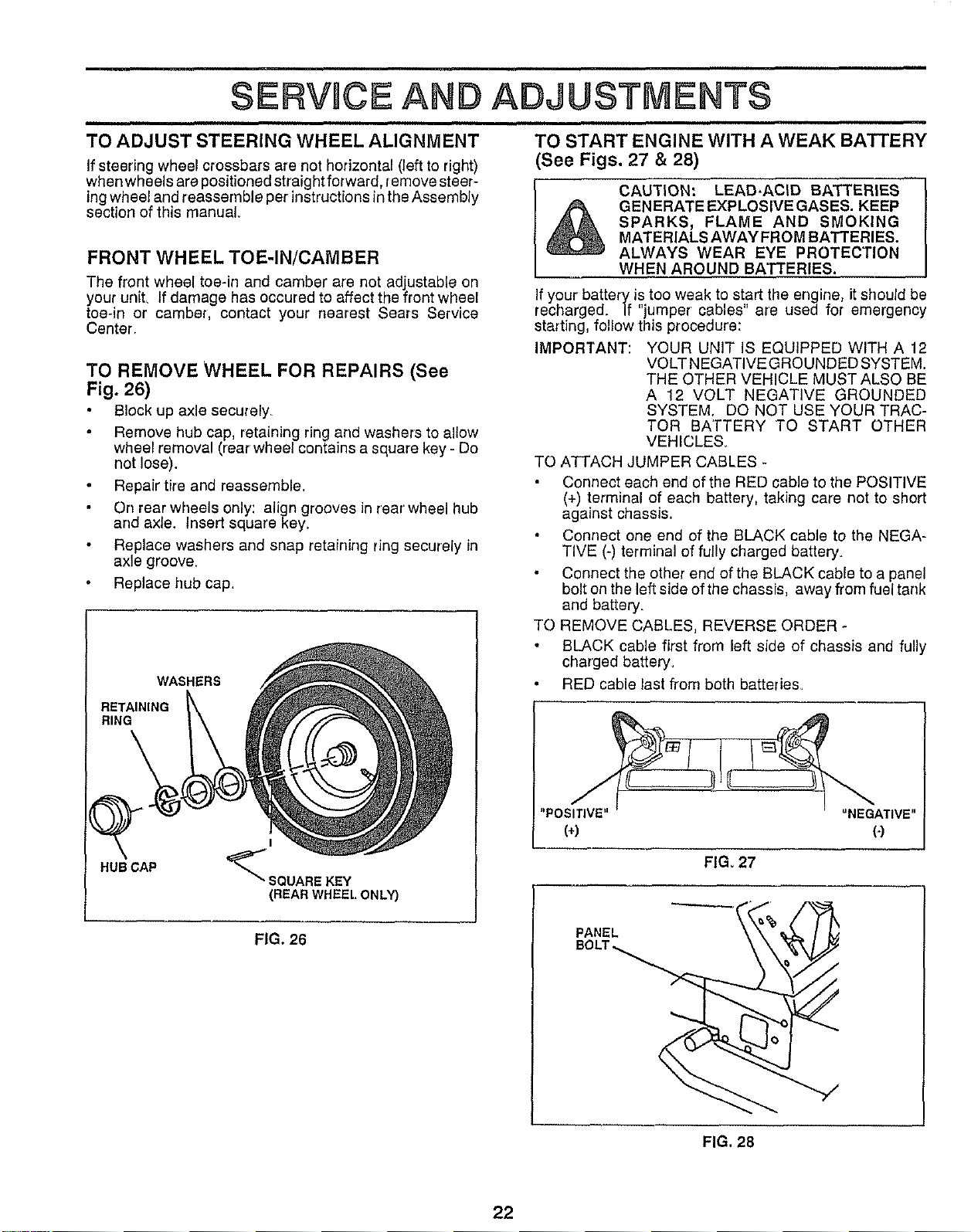
TO REMOVE WHEEL FOR REPAIRS (See
Fig. 26)
Block up axle securely
Remove hub cap, retaining ring and washers to allow
wheel removal (tear wheel contains a square key - Do
not lose).
Repair tire and reassemble.
On rear wheels only: align grooves in rear wheel hub
and axle. Insert square key_
Replace washers and snap retaining ring securely in
axle groove.
Replace hub cap.
WASHERS
RETAINING
RING
HUBCAP
I
_SQUARE KEY
(REAR WHEELONL_
FIG. 26
CAUTION: LEAD.ACID BATTERIES
GENERATE EXPLOSIVEGASES. KEEP
SPARKS, FLAME AND SMOKING
MATERIALS AWAY FROM BATTERIES.
ALWAYS WEAR EYE PROTECTION
WHEN AROUND BATTERIES.
If your battery is too weak to start the engine, it should be
recharged, ff "jumper cables" are used for emergency
starting, follow this procedure:
IMPORTANT: YOUR UNIT IS EQUIPPED WITH A 12
VOLT NEGATIVEGROUNDED SYSTEM.
THE OTHER VEHICLE MUST ALSO BE
A 12 VOLT NEGATIVE GROUNDED
SYSTEM, DO NOT USE YOUR TRAC-
TOR BATTERY TO START OTHER
VEHICLES.
TO ATTACH JUMPER CABLES -
Connect each end of the RED cable to the POSITIVE
(+) terminal of each battery, taking care not to short
against chassis.
Connect one end of the BLACK cable to the NEGA-
TIVE (-) terminal of fully charged battery.
Connect the other end of the BLACK cable to a panel
bolt on the left side of the chassis, away from fuel tank
and battery.
TO REMOVE CABLES, REVERSE ORDER -
BLACK cable first from left side of chassis and fully
charged battery,
RED cable last fl'om both batteries_
FIGo 27
BOLT_ \ _j
FIG. 28
22
SERVICE AI ADJUSTMENTS
HOOD
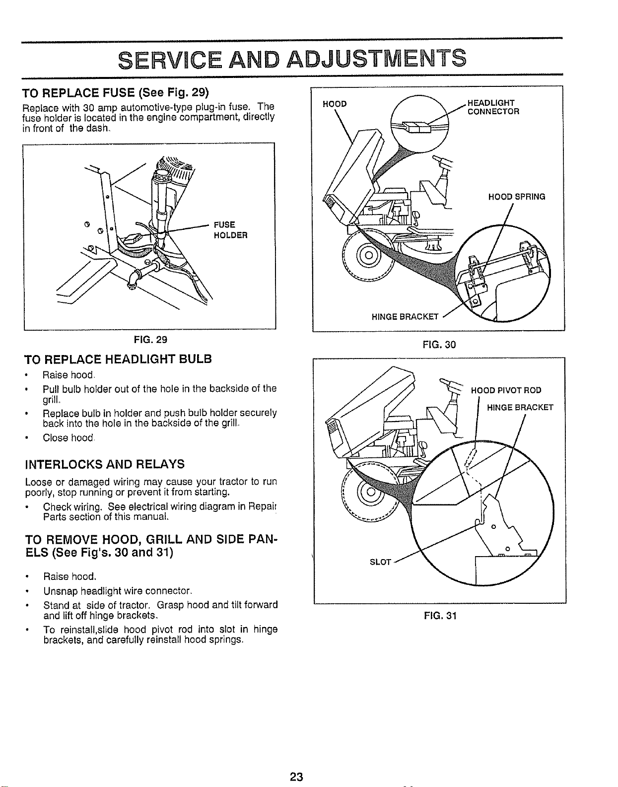
TO REPLACE FUSE (See Fig. 29)
Replace with 30 amp automotive-type plug-in fuse. The
fuse holder is located in the engine compartment, directly
in front of the dash.
FUSE
C HOLDER
FIG. 29
TO REPLACE HEADLIGHT BULB
Raise hood.
Pull bulb holder out of the hole in the backside of the
grille
Replace bulb in holder and push bulb holder securely
back into the hole in the backside of the grill.
Close hood.
INTERLOCKS AND RELAYS
Loose or damaged wiring may cause your tractor to run
poorly, stop running or prevent it from starting.
Check wiring. See electrical wiring diagram in Repair
Parts section of this manual.
TO REMOVE HOOD, GRILL AND SIDE PAN-
ELS (See Fig's. 30 and 31)
Raise hood.
Unsnap headlight wire connector.
Stand at side of tractor. Grasp hood and tilt forward
and lift off hinge brackets.
To reinstall,slide hood pivot rod into slot in hinge
brackets, and carefully reinstall hood springs.
HEADLIGHT
NECTOR
HOOD SPRING
HINGE BRACKET
FIG. 30
HOOD PIVOT ROD
HINGE BRACKET
SLO1
FIG. 31
23
ERVHCEAN ADJUSTMENTS
ENGINE
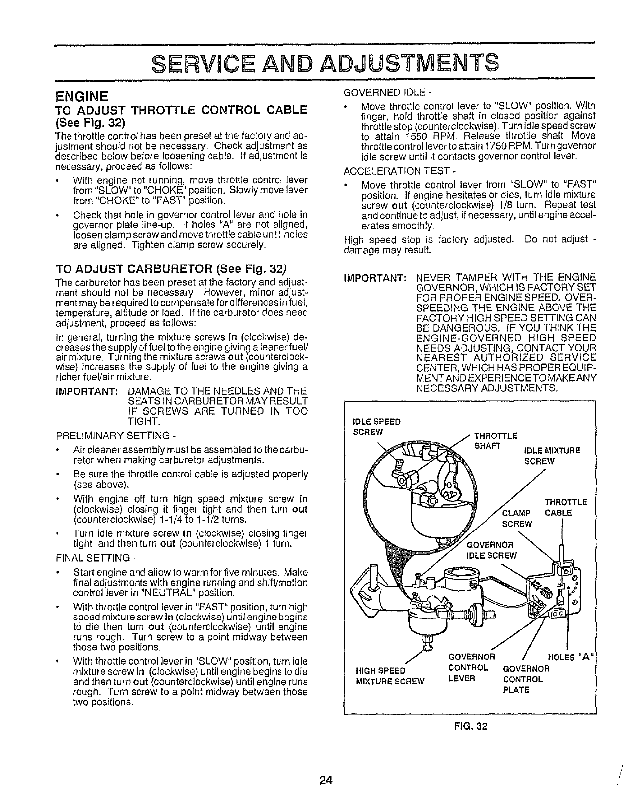
TO ADJUST THROTTLE CONTROL CABLE
(See Fig. 32)
The throttle control has been preset at the factory and ad-
ustment should not be necessary. Check adjustment as
descr bed be ow before loosening cable_ If adjustment is
necessary, proceed as follows:
With engine not running, move throttle control lever
from "SLOW" to "CHOKE" position. Slowly move lever
lrom "CHOKE" to "FAST" position.
Check that hole in governor control lever and hole in
governor plate line-up. If holes "A" are not aligned,
loosen clamp screw and move throttle cable until holes
are aligned. Tighten clamp screw securely.
TO ADJUST CARBURETOR (See Fig. 32)
The carburetor has been preset at the factory and adjust-
ment should not be necessary. However, minor adjust-
ment may be required to compensate fordifferences infuel,
temperature, altitude or load Ifthe carburetor does need
adjustment, proceed as follows:
In general, turning the mixture screws in (clockwise) de-
creases the supply of fuel to the engine giving a leaner fuel/
air mixture. Turning the mixture screws out (counterclock-
wise) increases the supply of fuel to the engine giving a
richer fuel/air mixture.
IMPORTANT: DAMAGE TO THE NEEDLES AND THE
SEATS IN CARBURETOR MAY RESULT
IF SCREWS ARE TURNED IN TOO
TIGHT,
PRELIMINARY SETTING -
Air cleaner assembly must be assembled to the carbu-
retor when making carburetor adjustments.
Be sure the throttle control cable is adjusted properly
(see above).
With engine off turn high speed mixture screw in
(clockwise) closing it finger tight and then turn out
(counterclockwise) 1-1/4 to 1-1/2 turns.
Turn idle mixture screw in (clockwise) closing finger
tight and then turn out (counterclockwise) 1turn.
FINAL SETTING -
Start engine and allow to warm for five minute& Make
final adjustments with engine running and shift!motion
control lever in "NEUTRAL" position.
With throttle control lever in "FAST" position, turn high
speed mixture screw in (clockwise) until engine begins
to die then turn out (counterclockwise) until engine
runs rough. Turn screw to a point midway between
those two position&
With throttle control lever in "SLOW" position, turn idle
mixture screw in (clockwise) until engine begins to die
and then turn out (counterclockwise) until engine runs
rough. Turn screw to a point midway between those
two positions.
GOVERNED IDLE -
Move throttle control lever to "SLOW" position. With
finger hold throttle shaft in closed position against
throttle stop (counterclockwise). Turn idle speed screw
to attain 1550 RPM. Release throttle shaft. Move
throttle control lever to attain 1750 RPM. Turn governor
idle screw until it contacts governor control lever.
ACCELERATION TEST -
Move throttle control lever from "SLOW" to "FAST"
position. If engine hesitates or dies, turn idle mixture
screw out (counterclockwise) 1/8 turn. Repeat test
and continue to adjust, if necessary, until engine accel-
erates smoothly_
High speed stop is factory adjusted. Do not adjust -
damage may result.
IMPORTANT: NEVER TAMPER WITH THE ENGINE
GOVERNOR, WHICH IS FACTORY SET
FOR PROPER ENGINE SPEED. OVER-
SPEEDING THE ENGINE ABOVE THE
FACTORY HIGH SPEED SETTING CAN
BE DANGEROUS, IF YOU THINK THE
ENGINE-GOVERNED HIGH SPEED
NEEDS ADJUSTING, CONTACT YOUR
NEAREST AUTHORIZED SERVICE
CENTER, WHICH HAS PROPER EQUIP-
MENTAND EXPERIENCETO MAKEANY
NECESSARY ADJUSTMENTS.
IDLE SPEED
SCREW
SHAFT
IDLE MIXTURE
SCREW
THROTTLE
CABLE
HIGH SPEED
MIXTURE SCREW
GOVERNOR
CONTROL
LEVER
HOLES"A'
GOVERNOR
CONTROL
PLATE
FIG. 32
24 /
STORAGE
Drain the fuel tank.
Immediately prepare your tractor for storage at the end of
the season or ifthe unit will net be used for 30 days or more
CAUTION: NEVER STORE THE TRAC-
TOR WITH GASOLLNE IN THE TANK
INSIDE A BUILDING WHERE FUMES
MAY REACH AN OPEN FLAME OR
SPARK. ALLOWTHE ENGINETO COOL
BEFORE STORING IN ANY ENCLO-
SURE.
TRACTOR
Remove mower from tractor for winter storage. When
mower is to be stored for a period of time, clean it thor-
oughly, remove all dirt. grease, leaves, etc. Give blades
and underside of housing a good coat of grease or rust
preventative. Store in a clean, dry area,
Clean entire tractor (See "CLEANING" in the Mainte-
nance section of this manual)
Inspect and replace belts, if necessary (See belt re-
placement instructions in the Service and Adjustments
section of this manual).
Lubricate as shown in the Maintenance section of this
manual
Be sure that all nuts. bolts and screws are securely
fastened Inspect moving parts for damage, breakage
and wear, Replace if necessary.
Touch up all rusted or chipped paint surfaces; sand
lightly before painting.
BATTERY
Fully charge the battery for storage
After a period of time in storage, battery may require
recharging.
To help prevent corrosion and power leakage during
long periods of storage, battery cables should be dis-
connected and battery cleaned thoroughly (see "TO
CLEAN BATTERY AND TERMINALS" in the Mainte-
nance section of this manual).
After cleaning, leave cables disconnected and place
cables where they cannot come in contact with battery
terminals.
Be sure battery drain tube is securely attached to drain
in battery tray.
ENGINE
FUEL SYSTEM
IMPORTANT: IT IS IMPORTANT TO PREVENT GUM
DEPOSITS FROM FORMING IN ESSEN-
TIAL FUEL SYSTEM PARTS SUCH AS
CARBURETOR. FUEL FILTER, FUEL
HOSE, OR TANK DURING STORAGE.
ALSO, EXPERI ENCE INDICATES THAT
ALCOHOL BLENDED FUELS (CALLED
GASOHOL OR USING ETHANOL OR
METHANOL) CAN ATTRACT MOISTU RE
WHICH LEADS TO SEPARATION AND
FORMATION OFACIDS DURING STOR-
AGE. ACIDIC GAS CAN DAMAGE THE
FUEL SYSTEM OF AN ENGINE WHILE
IN STORAGE.
Start the engine and let it run until the fuel lines and
carburetor are empty.
Never use engine or carburetor cleaner products in the
fuel tank or permanent damage may occur
Use fresh fuel next season.
NOTE: Fuel stabilizer is an acceptable alternative in mini-
mizing the formation of fuel gum deposits during storage.
Add stabilizer to gasoline in fuel tank or storage container.
Always follow the mix ratio found on stabilizer container.
Run engine at least 10 minutes after adding stabilizer to
allow the stabilizer to reach the carburetor. Do not drain the
gas tank and carburetor if using fuel stabilizer.
ENGINE OIL
Drain oil (with engine warm) and replace with clean engine
oil (See "ENGINE" in the Maintenance section of this
manual),
CYLINDERS
Remove spark p[ug(s)_
Pour one ounce of oil through spark plug hole(s) into
cylinderr
Turn ignition key to "START" position for a few seconds
to distribute oil
Replace with new spark plug(s).
OTHER
Do net store gasoline from one season to another
Replace your gasoline can if your can starts to rust.
Rust and/or dirt in your gasoline will cause problems
If possible, store your unit indoors and cover it to give
protection from dust and dirL
Cover your unit with a suitable protective cover that
does not retain moisture. Do not use plastic Plastic
cannot breathe which allows condensation to form and
will cause your unit to rust,
IMPORTANT: NEVER COVER TRACTOR WHILE EN-
GINE AND EXHAUSTAREAS ARE STILL
WARM,
25

TROUBLESHOOTJ
POINTS
PROBLEM
Willnotstart
Hard to start
Engine will not turn over
Engine clicks but will not
start
Loss of power
Excessive vibration
CAUSE
1, Out of fuel
2, Engine not "CHOKED" properly.
3, Engine flooded
4 Bad sparkplug=
5. Dirty air filter:
6. Dirty fuet fitter
7 Water in fuel
8_ Loose or damaged wiring
9, Carburetor out of adjustment
10 Engine valves out of adjustment
1 Dirty air filter
2 Sad spark plug.
3 Week or dead battery
4. Dirty fuet filter
5. Stale or dirty fuel
6 Loose or damaged wiring
7, Carburetor out of adjustment
8 Englne valves out of adjustment
1 Clutch/brake pedalnot depressed
2. Attachment clutchtsengaged
3 Sparkplugwtrels disconnected
4 Weak or dead battery
5 Blown fuse
6 Corroded batterytermlnals
7 Looseor damagedwlrlng
8 Faulty ignitionswitch
9. Faulty solenoid or starter
10 Faulty operator presenceswltch(es)
1. Weak or dead battery
2, Corroded battery terminals
3. Loose or damagedwldng
4, Faultysolenold or starter
1. Cutting too much grass/too fast
2 Throttle In"CHOKE" position,
3. Build-up of grass, leaves and trash under mower
4. Dirty air filter.
5. Low oli level/dirty ell
6 Faulty spark ptug
7 Dirty rue! filter
8 Stale or dirty fueI
9 Water It] fuel.
10 Spark plug wireloose
11 Dirty engine air screen/fins
12 Dirty/dogged muffler
13 Loose or damaged wldng
14, Carburetor out of adjustment
15. Engine valves out ofadjustment
f Worn, bent or loose blade
2 Bentblade mandrel.
3. Loose/damaged part(s)
CORRECTION
1, Fill fuel tank
2 See TO START ENGINE In operation section
3 Wait several minutes before attempting to start
4, Replace spark plug,
5, Clean/replace air filter
6. Replace fuel filter,
7. Drain fuel tank end carburetor, refill tank with fresh
gasoUno and replace fuel fitter.
8= Check all wiring,
9 Contact Sears Service Department.
10 Contact Sears Service Department
1 Clean/replace air filter
2. Replace spark plug
3 Recharge or replace battery.
4. Replace fuel filter
5, Drain fuel tank and refill with fresh gasotlne
6 Checka[iwlrlng,
7. Contact Sears Service Department
8 Contact Sears Service Department
1 Depress Clutch/brake pedal.
2 Disengage attachment clutch
3. Connect wire tospark plug,
4_ Recharge or rsptace battery
5 Replace fuse
6. Clean battery terminals
7 Check aliwlrlng
8 Check/replace ignitionswitch
9 Check/replace solenoid or starter
10 Contact Sears Service Department.
1 Rechargeor replace battery
2 Clean batterytermlnals
3. Check all wiring
4, Cheeldreplace solenoid orstarter,
1 Set In "Higher Cut" position/reduce speed
2 Adjust throttlecontrol,
3 Clean underside of mower housing.
4 Clean/replace air filter.
5_ Check oillevel/changeoil
6 Clean and regap or changespark plug,
7 Replace fuel filter
8 Draln fuel tank and refill with fresh gasoline,
9, Drain fuel tank and carburetor, refill tank with fresh
gasoline and replace fuel filter.
10. Connect andtighten spark plugwire
11 Clean engine air screen/fins
12 Clean/replace muffler
13. Check all wiring.
14_ Contact Sears Service Department.
15 Contact Authorized Service Facility
1 Replace blade, Tighten blade bolt_
2. Replace blade mandrel,
3 Tighten loose part(s) Reptace damaged parts
26


