Loading ...
Loading ...
Loading ...
MAINTENANCE SCHEDULE
Perform these required maintenance procedures at the frequency
stated in the table. These procedures should also be a part of any
seasonal tune-up.
NOTE: Some maintenance procedures may require special tools or
NOTE:
skills. If you are unsure about these procedures take your unit
to any non-road engine repair establishment, individual or
authorized service dealer.
Maintenance, replacement, or repair of the emission control
devices and system may be performed by any non-road engine
repair establishment, individual or authorized service dealer.
[,_ WARNING: To prevent serious injury, never perform
maintenance or repairs with unit running. Always service
and repair a cool unit. Disconnect the spark plug wire to
ensure that the unit cannot start.
FREQUENCY MAINTENANCE REQUIRED SEE
Fill fuel tank with fresh fuel Page 4
Before starting engine Check oil Page 7
Every 10 hours Clean and re-oil air filter Page 8
First change at 10 hours Change oil Page 7
Every 25 hours thereafter Change oil Page 7
Every 25 hours Clean spark arrestor Page 10
10 hours on new engine
Every 25 hours
Every 25 hours
Check rocker arm to valve
clearance and adjust
Check rocker arm to valve
clearance and adjust
Check spark plug
condition and gap
Page 9
Page 9
Page lO
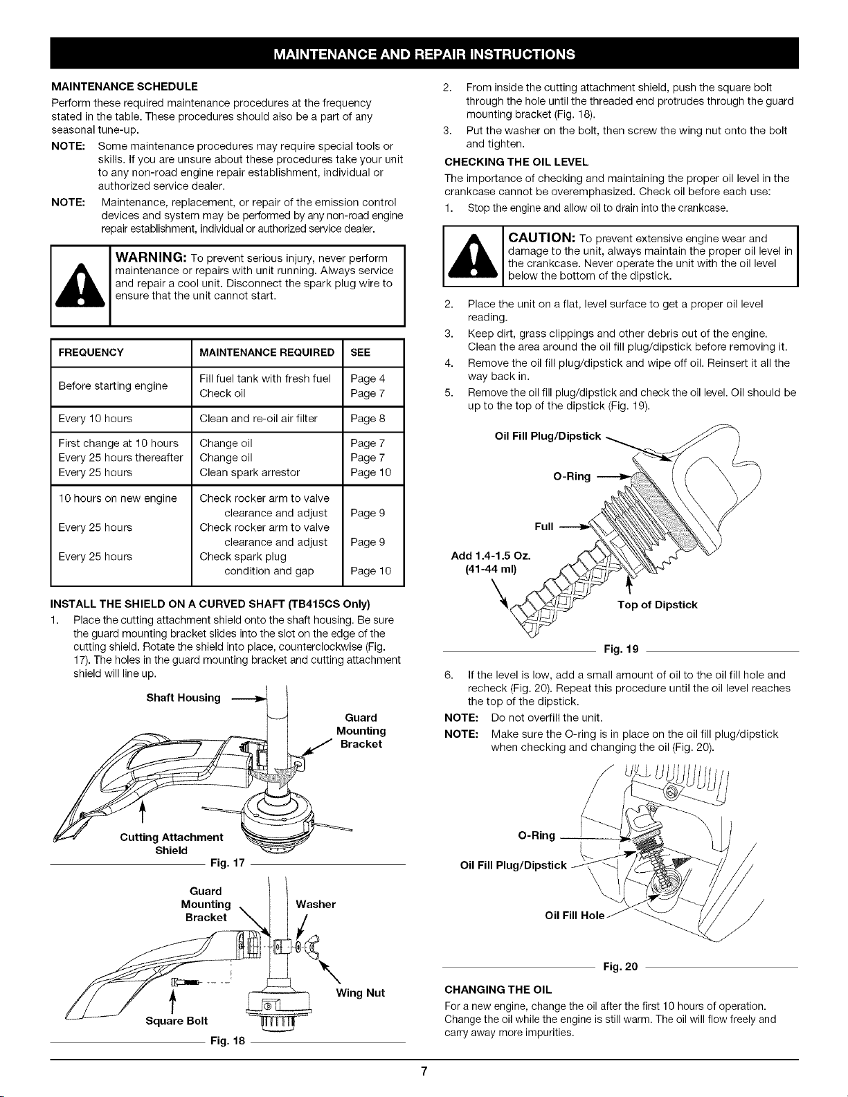
INSTALL THE SHIELD ON A CURVED SHAFT (TB415CS Only)
1. Place the cutting attachment shield onto the shaft housing. Be sure
the guard mounting bracket slides into the slot on the edge of the
cutting shield. Rotate the shield into place, counterclockwise (Fig.
17). The holes in the guard mounting bracket and cutting attachment
shield will line up.
Shaft Housing
Guard
_ Mounting
_ Bracket
Cutting Attachment
Shield
Fig. 17
Guard
Mounting
Bracket
Washer
2. From inside the cutting attachment shield, push the square bolt
through the hole until the threaded end protrudes through the guard
mounting bracket (Fig. 18).
3. Put the washer on the bolt, then screw the wing nut onto the bolt
and tighten.
CHECKING THE OIL LEVEL
The imporfance of checking and maintaining the proper oil level in the
crankcase cannot be overemphasized. Check oil before each use:
1. Stop the engine and allow oil to drain into the crankcase.
,_ CAUTION: To prevent extensive engine wear and I
damage to the unit, always maintain the proper oil level in
the crankcase. Never operate the unit with the oil level
below the bottom of the dipstick.
2. Place the unit on a flat, level surface to get a proper oil level
reading.
3. Keep dirt, grass clippings and other debris out of the engine.
Clean the area around the oil fill plug/dipstick before removing it.
4. Remove the oil fill plug/dipstick and wipe off oil. Reinsert it all the
way back in.
5. Remove the oil fill plug/dipstick and check the oil level. Oil should be
up to the top of the dipstick (Fig. 19).
Oil Fill
O-Ring
Add 1.4-1.5 Oz.
(41-44 ml)
\
Full
Top of Dipstick
Fig. 19
6. If the level is low, add a small amount of oil to the oil fill hole and
recheck (Fig. 20). Repeat this procedure until the oil level reaches
the top of the dipstick.
NOTE: Do not overfill the unit.
NOTE: Make sure the O-ring is in place on the oil fill plug/dipstick
when checking and changing the oil (Fig. 20).
O-Ring
Oil Fill Hole
t
Square Bolt
Fig. 18
Wing Nut
Fig. 20
CHANGING THE OIL
For a new engine, change the oil after the first 10 hours of operation.
Change the oil while the engine is still warm. The oil will flow freely and
carry away more impurities.
Loading ...
Loading ...
Loading ...