
Loading ...
Loading ...
Loading ...
OilFill
Fig. 2
O-Ring
Oil Fill Plug/Dipstick /
/
Oil Fill Hole
Fig. 3
equivalent, will inhibit corrosion and minimize the formation of gum
deposits. Using a fuel additive can keep fuel from forming harmful
deposits in the carburetor for up to six (6) months. Add 0.8 oz. (23 ml.)
of fuel additive per gallon of fuel according to the instructions on the
container. NEVER add fuel additives directly to the unit's gas tank.
I
WARNING:
Add fuel in a clean, well ventilated outdoorI
area. Wipe up any spilled fuel immediately. Avoid creating I
a source of ignition for spilt fuel. Do not start the engine I
until fuel vapors dissipate.
FUELING THE UNIT
'_1 WARNING: Gasoline is extremely flammable. Ignited I
I
vapors may explode. Always stop the engine and allow it to
cool before filling the fuel tank. Do not smoke while filling the I
tank. Keep sparks and open flames at a distance from the
area.
1. Remove the fuel cap (Fig. 4).
Gas Can
cap
FuelTank
Fig. 4
[,_ ARNING: Remove fuel cap slowly to avoid injury from
fuel spray. Never operate the unit without the fuel cap
securely in place.
2. Place the gas container's spout into the fill hole on the fuel tank
(Fig. 4) and fill the tank.
NOTE: Do not overfill the tank.
3. Wipe up any gasoline that may have spilled.
4. Reinstall the fuel cap.
5. Move the unit at least 30 ft. (9.1 m) from the fueling source and
site before starting the engine.
NOTE: Dispose of the old gasoline in accordance to Federal, State
and Local regulations.
ADJUSTING THE D-HANDLE
NOTE: The D-handle comes mounted on the backside of the shaft.
1. Locate the wing nut on the D-Handle. Untighten the wing nut
enough to loosen the D-Handle (Fig. 5).
NOTE: Do not remove wing nut, washer, or bolt.
2. Rotate the D-Handle to the
upright position on the front side
of the shaft housing (Fig. 5).
NOTE: The D-handle should slant
towards the powerhead of
the unit.
3. Hold the unit in the operating
position. If necessary, reposition _,,
the D-handle to the location that _
L
provides the best grip (Fig. 11).
4. Tighten the wing nut until the D-
Handle is secure. Fig. 5
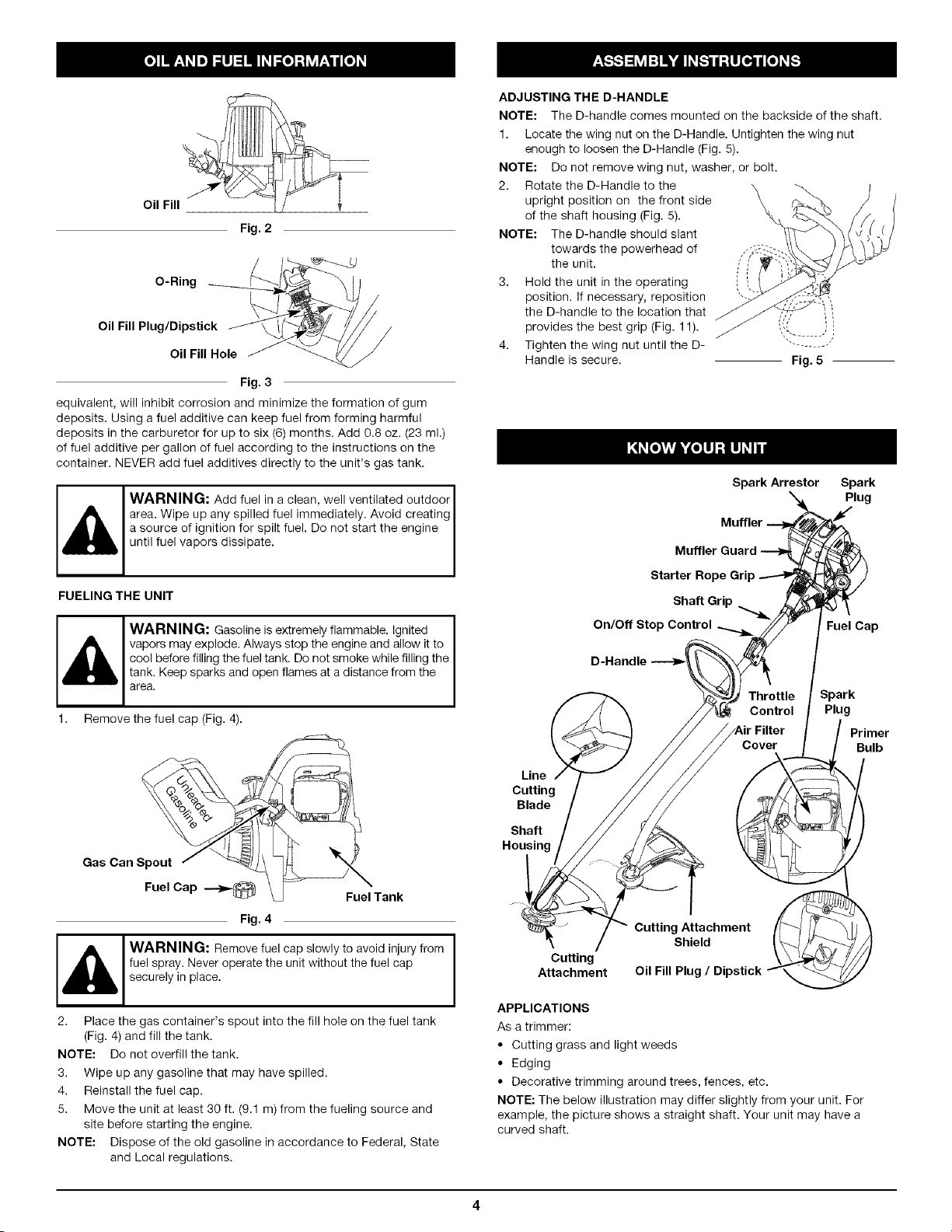
Spark Arrestor Spark
Plug
Muffler Guard
Starter
Shaft Grip
On/Off Stop Control
Fuel Cap
Line
Cutting
Blade
Shaft
Housing
Spark
Plug
Primer
Bulb
Cutting
Attachment
Cutting Attachment
Shield
Oil Fill Plug / Dipstick
APPLICATIONS
As a trimmer:
• Cutting grass and light weeds
• Edging
• Decorative trimming around trees, fences, etc.
NOTE: The below illustration may differ slightly from your unit. For
example, the picture shows a straight shaft. Your unit may have a
curved shaft.
Loading ...
Loading ...
Loading ...