Loading ...
Loading ...
Loading ...
18
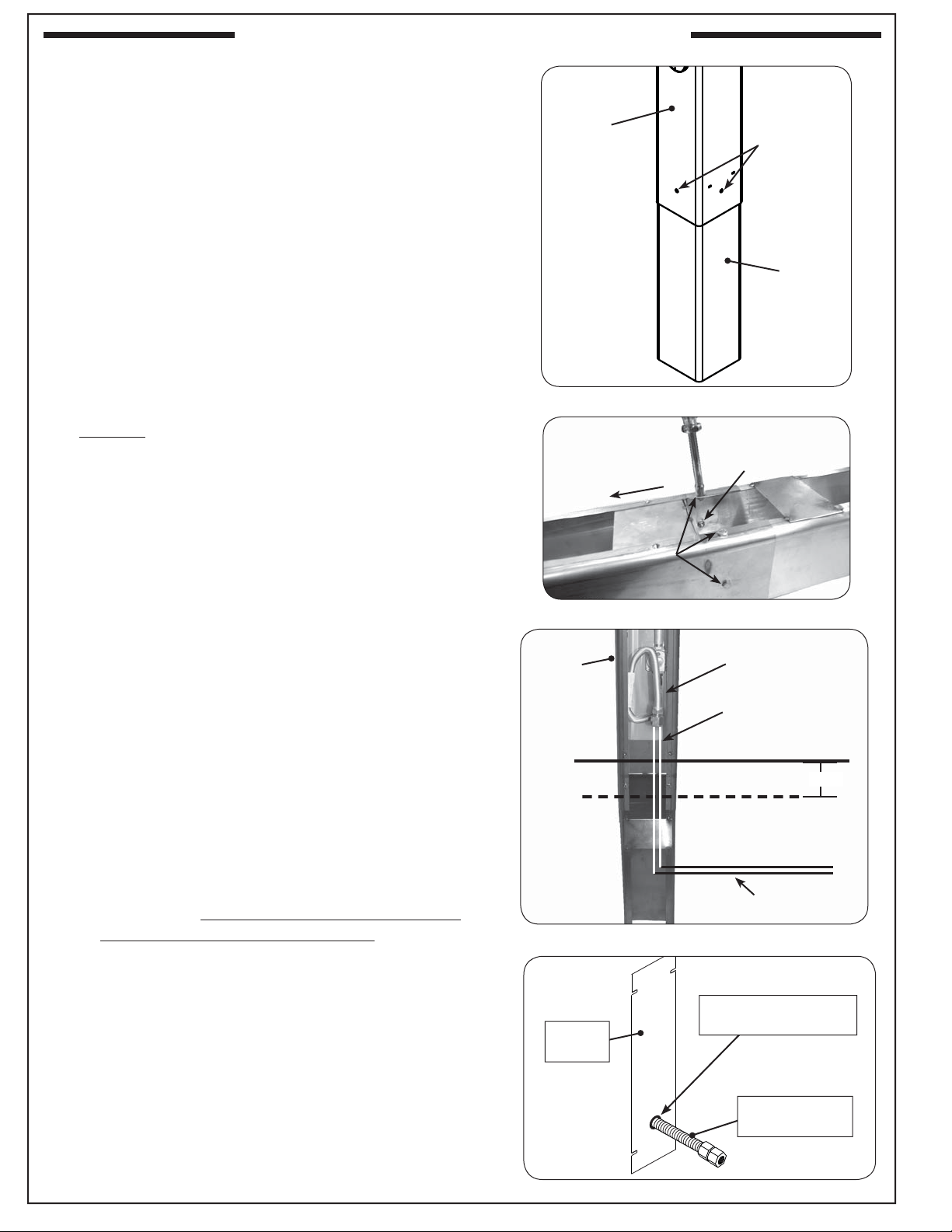
ATTACH POST EXTENSION
1. Attach the extension to the bottom of the grill post so
that the open portion is toward the back of the grill and
the fi ve holes in the extension line up with the fi ve (5)
weld-nuts in the post (see Fig. 18-1).
2. From outside the joined post and extension, insert
one of the
1
/
4
X 20"-
5
/
8
bolts (supplied) into each of
the fi ve (5) bolt holes and tighten each using a
7
/
16
"
socket driver or wrench (see Fig. 18-2).
Note: There is one hole on each side of the post,
except the back which has two holes located on
either side of the extension opening.
PLACE POST IN-GROUND & POUR
CONCRETE
1. Prepare the concrete to be used for the install.
2. Carefully orient the post over the gas supply line and
into the installation hole.
Important: Verify that the gas supply line is running up
through the post hole, just off center. It must
extend high enough to reach the grill gas
connection and remain safely above the level
of the concrete when poured.
3. Remove the post, then cover the end of the gas supply
line with a plastic bag and/or masking tape to avoid
getting concrete or other debris in the supply line.
4. Pour the concrete into the hole 3-5" below ground
level taking care to protect the gas supply line.
5. While the concrete is still wet, carefully lower the
extended grill post into the hole so that the gas
supply line slides through the clearance hole in the
bottom of the post.
6. Orient the grill per plan, then level the grill and support
it so that it remains in position while the concrete drys.
ROUTE FLEX CONNECTOR (ABOVE GROUND
METHOD ONLY)
Note: This section addresses an above ground gas
supply setup. If connecting underground, skip this
section and continue with installation.
The gas supply line will need to be run to the post install
location as appropriate for the desired setup.
To route fl ex connector through rear of post:
1. Remove the knock-out disk at the bottom of the access
plate with a large fl athead screwdriver. (Insert the
screwdriver into the notch provided in the center of
the knock-out.)
2. Remove the plastic grommet (attached to the fl ex
connector) and insert it into the newly created opening.
Then route the fl ex connector through the opening.
See Fig. 18-4.
Bolts
Weld-nut
To grill
Post
Extension
(position
open side
toward back)
Install
provided bolts
into 5 holes
around post
Fig. 18-1 Install extension to post
Fig. 18-2 Fasten extension to post
Ground level
Concrete level
Post
Gas supply route
Fig. 18-3 Pour concrete & install post
3-5"
Gas supply line
(cover to protect)
Flex connector
(w/ adapter)
Fig. 18-4 Access plate view & install orientation
Access
plate
Gas supply knock-out
(grommet installed)
Flex connector
(w/ adapter)
IN-GROUND POST INSTALLATION (cont.)
Loading ...
Loading ...
Loading ...