Loading ...
Loading ...
Loading ...
18 49-6000245 Rev. 2
INSULATION BLANKETS
This water heater is designed for energy efficiency.
An insulation blanket is NOT RECOMMENDED,
unless required by local codes.
Any damage caused by an insulation blanket or other
unapproved device is not covered under the warranty.
Use of such devices can shorten the life of the water
heater and pose a hazard to persons or property.
If an insulation blanket is required by local codes:
• DO NOT cover or attempt to relocate warning
labels on the water heater.
• DO NOT insulate the top of the water heater; this
will interfere with proper functioning of the vent
hood.
• DO NOT cover the gas control/thermostat, gas
valve, burner access door or temperature and
pressure relief valve.
• DO NOT insulate the bottom of the water heater or
cover the combustion air inlets.
• FREQUENTLY INSPECT the insulation blanket
to ensure that it is securely in position and is not
restricting airflow to the combustion air inlets at the
base of the water heater.
Installation Instructions
INSTALLATION INSTRUCTIONS
GAS SUPPLY
WARNING
Only connect this water heater
to the type of gas listed on its rating plate. Any
attempt to adapt the water heater for use with
a different type of gas could cause hazardous
operating conditions.
The gas supply line should be composed of an
approved gas piping material such as steel and
properly sized for the water heater. Install an ANSI
certified gas appliance connector or ground joint
union in the gas line close to the water heater.
Any flexible connectors in the gas line must be 36”
or shorter. Joint compound should be used sparingly
on male threads only and must be resistant to liquid
petroleum (LP) gas.
The National Fuel Gas Code (NFGC) requires that a
manual gas shut-off valve be installed.
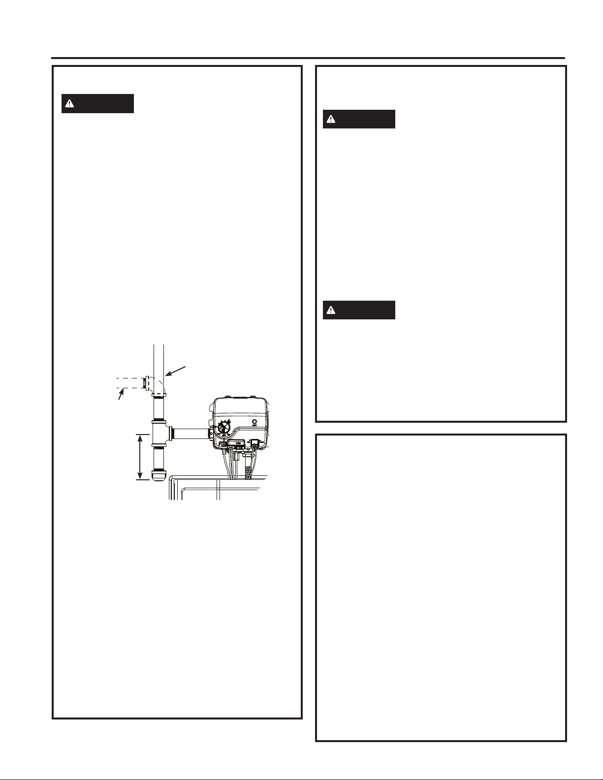
A sediment trap must be installed downstream of the
shut-off valve, as close to the appliance as possible.
Refer to the illustration below.
Connect the pipe to the gas control/thermostat inlet
using a maximum torque of 40 ft-lbs. torque.
Gas pressure to the gas control/thermostat inlet
must not exceed 14” w.c. for natural gas or LP gas.
For purposes of input adjustment, the minimum
inlet gas pressure (with main burner on) is shown
on the water heater rating plate. If gas pressure is
not within the acceptable range, contact your gas
provider.
Pressure Testing
• Gas test pressures exceeding 14” w.c. (1/2 PSI or
3.5 kPa) require disconnecting the water heater
and gas shut-off valve from the gas supply line.
• Gas test pressures of 14” w.c. (1/2 PSI or 3.5 kPa)
or lower require isolating the water heater from the
gas supply line by closing the gas shut-off valve.
3” minimum
Sediment Trap
Gas Supply Line
(vertical install)
Gas Supply Line
(horizontal install)
GAS SUPPLY (Cont.)
Leak Testing
WARNING
Never use an open flame to test for
gas leaks, as property damage, personal injury, or
death could result.
• The water heater and its gas connections must be
leak tested at normal operating pressure before
placing the appliance in operation.
• Turn ON the manual gas shut-off valve near water
heater and check for leaks by applying a soapy
water mixture on all gas fittings, including the
factory connections to the Combination Gas Control
(thermostat). Presence of bubbles indicate a gas
leak, which must be corrected before completing
installation.
High Altitude
WARNING
Do not install the water heater
above the altitude specified on its rating plate.
Installation above the certified altitude may cause
the water heater to produce excessive amounts
of carbon monoxide, which could cause serious
injury or death.
The water heater is certified for operation at high
altitudes. Please see the rating plate on the water
heater for maximum altitude.
Loading ...
Loading ...
Loading ...