Loading ...
Loading ...
Loading ...
COTTER
EXTENSION f_
SPRING COTTER PiN
BRAKE,
ROD
LH. PIVOT j
BRACKET
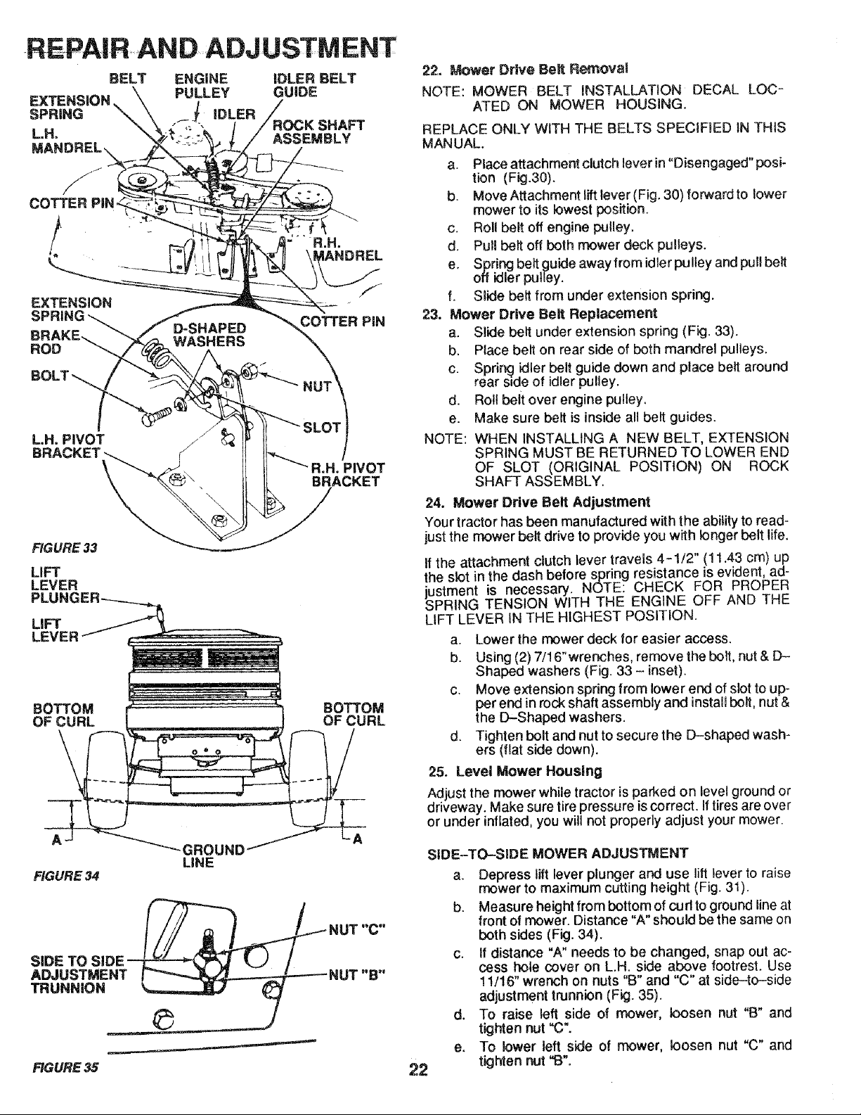
FIGURE 33
LiFT
LEVER
LiFT
LEVER
BOTTOM
OF CURL
R.H. PIVOT
BRACKET
BOTTOM
OF CURL
22. Mower Drive Belt Removal
NOTE: MOWER BELT INSTALLAT!ON DECAL LOC-
ATED ON MOWER HOUSING.
REPLACE ONLY WITH THE BELTS SPECiFiED IN THiS
MANUAL.
a. Place attachment clutch lever in "Disengaged" posi-
tion (Fig.30).
b. Move Attachment liftlever (Fig. 30) forward to lower
mower to its lowest position.
c. Roll belt off engine pultey.
d. Pull belt off both mower deck pulleys.
e. Spring belt guide away from idler pulley and pull belt
off idler pulley.
fo Slide belt from under extension spring.
23. Mower Drive Belt Replacement
a. Slide belt under extension spring (Fig. 33).
b. Place belt on rear side of both mandrel pulleys.
c. Spdr_j idler belt guide down and place belt around
rear s_de of idler pulley.
d. Roll belt over engine pulley.
e. Make sure belt is inside all belt guides.
NOTE: WHEN INSTALLING A NEW BELT, EXTENSION
SPRING MUST BE RETURNED TO LOWER END
OF SLOT (ORIGINAL POSITION) ON ROCK
SHAFT ASSEMBLY.
24. Mower Drive Belt Adjustment
Your tractor has been manufactured with the ability to read-
just the mower belt drive to provide you with longer belt life.
If the attachment clutch lever travels 4-1/2" (! 1.43 cm) up
the slot in the dash before spring resistance is evident, ad-
justment is necessary. NOTE: CHECK FOR PROPER
SPRING TENSION WtTH THE ENGINE OFF AND THE
LIFT LEVER IN THE HIGHEST POSITION.
a. Lower the mower deck for easier access.
b. Using (2) 7/16"wrenches, remove the bolt, nut & D-
Shaped washers (Fig. 33 - inset).
c. Move extension spring from lower end of slot to up-
per end in rock shaft assembly and install belt, nut &
the D-Shaped washers.
d. Tighten bolt and nut to secure the D-shaped wash-
ers (flat side down).
25. Level Mower Housing
Adjust the mower while tractor is parked on level ground or
driveway. Make sure tire pressure _scorrect. If tires are over
or under inflated, you will not properly adjust your mower.
LiNE
FIGURE 34
"_aL_/NUT "C"
SIDE TO SIDE_ LJ /
FIGURE 35
22
SiDE-TO-SIDE MOWER ADJUSTMENT
a. Depress lift lever plunger and use lift lever to raise
mower to maximum cutting height (Fig. 31).
b. Measure height from bottom of curt to ground line at
front of mower. Distance "A" should be the same on
both sides (Fig. 34).
c. If distance "A" needs to be changed, snap out ac-
cess hole cover on LH. side above footrest. Use
! 1/!6" wrench on nuts "B" and "C" at side-to-side
adjustment trunnion (Fig. 35).
d. To raise left side of mower, loosen nut "B" and
tighten nut "C".
e. To lower left side of mower, loosen nut "C" and
tighten nut "B".
Loading ...
Loading ...
Loading ...