Loading ...
Loading ...
Loading ...
- 7 -
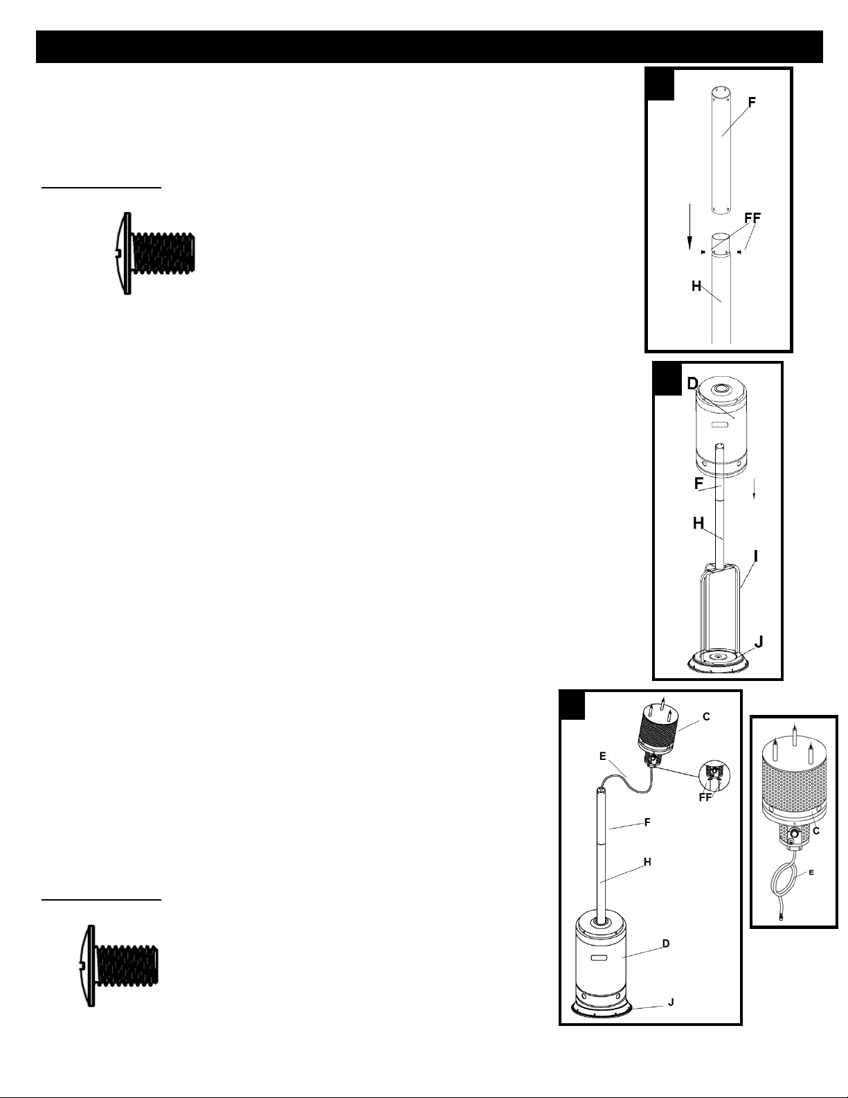
4. Attach Upper Post (F) to Lower Post (H). Align 4 small holes in Upper
Post with the 4 small holes in Lower Post and insert M6x10 (FF) screw. Using
Phillips screwdriver, tighten screw. Repeat with 3 more M6x10 (FF) screws
(total of 4 – M6x10 screws).
Hardware Used: 4 x FF, Screw M6x10
5. Place Tank Housing (D) onto Base (J). Slide Tank Housing (D) over
the assembled Upper/Lower Post and down over the Post Supports.
Rest Tank Housing on Base.
6. Attach Head Assembly (C) to Upper Post (F).
Note: There is a small piece of protective foam located in the
neck of the Head Assembly that MUST be removed prior to
attaching Head Assembly to the Upper Post.
Route Gas Hose (E) down into Upper/Lower post assembly and
align 4 small holes on Head Assembly with 4 Small holes in Upper
Post(F).
[HINT: Control knob should be above decal on post.]
Insert 4 M6x10 (FF) screws into holes and tighten with a Phillips
screwdriver.
Hardware Used
: 4 x FF, Screw M6x10
ASSEMBLY
4
5
6
Loading ...
Loading ...
Loading ...