OPERATION AND INSTALLATION INSTRUCTIONS
FOR THE LICENSED PLUMBER
INSTRUCCIONES DE FUNCIONAMIENTO E INSTALACIÓN
PARA EL PLOMERO MATRICULADO
MODE D’EMPLOI ET DIRECTIVES D’INSTALLATION
INSTALLATION À L’INTENTION DES PLOMBIERS AGRÉÉS
MINI-TANK ELECTRIC WATER HEATERS
CALENTADORES DE AGUA ELÉCTRICOS DE MINI-TANQUE
CHAUFFE-EAU ÉLECTRIQUES À MINI-RÉSERVOIR
» SHC 2.5
» SHC 4
Conforms to ANSI / UL Std. 174
Certified to CAN/ CSA Std. C22.2 No. 110
Conforme a ANSI/UL Std. 174
Certificación con CAN/CSA Std. C22.2 No. 110
Conforme à la norme ANSI/UL Std. 174
Certifié à la norme CAN/CSA Std. C22.2 No. 110
Tested and certified by WQA to NSF/ANSI372
for lead free compliance.
Probado y certificado por WQA NSF/ANSI 372 para
el cumplimiento de las regulaciones sin plomo.
Testé et certifié par WQA à la NSF/ANSI 372 pour
une utilisation sans plomb.
2 | SHC 2.5 / SHC 4 www.stiebel-eltron-usa.com
TABLE OF CONTENTS | OPERATION | INSTALLATION
1. General Information �����������������������������������3
2. Safety Precautions �������������������������������������3
3. Register your product ���������������������������������4
4. General Description ������������������������������������4
5. Technical Description ����������������������������������4
6. Technical Data ������������������������������������������5
6.1 Dimensions, SHC 2.5 �������������������������������������� 5
6.2 Dimensions, SHC 4 �����������������������������������������5
7. General Recommendations ���������������������������5
8. Mounting the Unit ��������������������������������������6
9. Plumbing Connections ��������������������������������� 6
9.1 Filling the Water Heater ���������������������������������� 7
10. Electrical Connection ����������������������������������7
10.1 Electrical diagram ����������������������������������������� 8
11. Settings �������������������������������������������������8
12. Maintenance Instructions �����������������������������8
12.1 Descaling the heating element �������������������������� 8
12.2 Venting the T&P relief valve �����������������������������8
12.3 Draining the water heater�������������������������������� 9
12.4 Removing the cover ��������������������������������������� 9
12.5 Removing the heating element �������������������������9
12.6 De-scaling the heating element������������������������� 9
12.7 Replacing the heating element ������������������������� 9
12.8 Changing the anode rod ���������������������������������10
12.9 Safety Shut-off ��������������������������������������������10
13. Limited Warranty �������������������������������������11
IMPORTANT SAFETY
INSTRUCTIONS
!
WARNING:
WHEN USING ELECTRICAL APPLIANCES, BASIC
SAFETY PRECAUTIONS TO REDUCE THE RISK OF
FIRE, ELECTRIC SHOCK, OR INJURY TO PERSONS
SHOULD BE FOLLOWED, INCLUDING:
1. READ ALL INSTRUCTIONS BEFORE USING THE
WATER HEATER.
2. This water heater must be grounded. Connect
only to properly grounded outlet. See the special
grounding instructions in chapter 10, “Electrical
Connection”, pg. 7-8.
3. Install or locate this water heater only in accor-
dance with the provided installation instructions.
4. Use this water heater only for its intended use as
described in this manual.
5. Do not use an extension cord with this water
heater. If no receptacle is available adjacent to the
water heater, contact a qualified electrician to have
one properly installed.
6. As with any appliance, close supervision is neces-
sary when used by children.
7. Do not operate this water heater if it has a dam-
aged cord or plug, if it is not working properly, or if
it has been damaged or dropped.
8. This water heater should be serviced only by
qualified service personnel. Contact nearest au-
thorized service facility for examination, repair, or
adjustment.
SAVE THESE INSTRUCTIONS
OPERATION
General Information
ENGLISH
www.stiebel-eltron-usa.com SHC 2.5 / SHC 4 | 3
1. General Information
!
CAUTION:
TO REDUCE THE RISK OF EXCESSIVE PRESSURES
AND TEMPERATURES IN THIS WATER HEATER, IN-
STALL TEMPERATURE AND PRESSURE PROTECTIVE
EQUIPMENT REQUIRED BY LOCAL CODES AND NO
LESS THAN A COMBINATION TEMPERATURE AND
PRESSURE RELIEF VALVE CERTIFIED BY A NA-
TIONALLY RECOGNIZED TESTING LABORATORY
THAT MAINTAINS PERIODIC INSPECTION OF PRO-
DUCTION OF LISTED EQUIPMENT OR MATERIALS,
AS MEETING THE REQUIREMENTS FOR RELIEF
VALVES AND AUTOMATIC GAS SHUTOFF DEVICES
FOR HOT WATER SUPPLY SYSTEMS, ANSI Z21.22.
THIS VALVE MUST BE MARKED WITH A MAXIMUM
SET PRESSURE NOT TO EXCEED THE MARKED
MAXIMUM WORKING PRESSURE OF THE WATER
HEATER. INSTALL THE VALVE INTO AN OPENING
PROVIDED AND MARKED FOR THIS PURPOSE IN
THE WATER HEATER, AND ORIENT IT OR PROVIDE
TUBING SO THAT ANY DISCHARGE FROM THE VALVE
EXITS ONLY WITHIN 6 INCHES ABOVE, OR AT ANY
DISTANCE BELOW, THE STRUCTURAL FLOOR, AND
DOES NOT CONTACT ANY LIVE ELECTRICAL PART.
THE DISCHARGE OPENING MUST NOT BE BLOCKED
OR REDUCED IN SIZE UNDER ANY CIRCUMSTANCES.
Read this entire manual. Failure to follow all the guides,
instructions and rules could cause personal injury or prop-
erty damage. Improper installation, adjustment, alteration,
service and use of this unit can result in serious injury.
This unit must be installed by a licensed electrician and
plumber. The installation must comply with all national, state
and local plumbing and electric codes. Proper installation
is the responsibility of the installer. Failure to comply with
the installation and operating instructions or improper use
voids the warranty.
Save these instructions for future reference. The installer
should leave these instructions with the consumer.
If you have any questions regarding the installation, use or
operation of this water heater, or if you need any additional
installation manuals, please call our technical service line
at 800-582-8423 (USA and Canada only). If you are calling
from outside the USA or Canada, please call 413-247-3380
and we will refer you to a qualified Stiebel Eltron service
representative in your area.
1. Do not locate the water heater where water lines
could be subject to freezing temperatures.
2. It is recommended to have a floor drain nearby to
permit easy draining of the unit if necessary.
3. Install the water heater so that in the event of a
leak, the resulting flow of water will not cause dam-
age to the area around the water heater. Under no
condition is the manufacturer liable for any water
damage in connection with this water heater.
4. When installing the water heater, ensure that clear-
ance around the unit is provided, for ease of main-
tenance and service.
!
THIS IS THE SAFETY ALERT SYMBOL.
IT IS USED TO ALERT YOU TO POTENTIAL PERSON-
AL INJURY HAZARD. OBEY ALL SAFETY MESSAGES
THAT FOLLOW THIS SYMBOL TO AVOID POSSIBLE
INJURY OR DEATH.
2. Safety Precautions
!
PLEASE READ AND FOLLOW THESE INSTRUC-
TIONS.
FAILURE TO FOLLOW THESE INSTRUCTIONS COULD
RESULT IN SERIOUS BODILY INJURY OR DEATH.
THE UNIT MUST BE INSTALLED BY A LICENSED
PLUMBER. THE INSTALLATION MUST COMPLY WITH
ALL NATIONAL, STATE AND LOCAL PLUMBING AND
ELECTRIC CODES.
SERVICE OF THE UNIT MUST BE PERFORMED BY A
QUALIFIED SERVICE AGENCY.
BEFORE PROCEEDING WITH ANY INSTALLATION,
ADJUSTMENT, ALTERATION, OR SERVICE OF THIS
UNIT THE POWER CORD SHOULD BE UNPLUGGED.
FAILURE TO DO SO COULD RESULT IN SERIOUS PER-
SONAL INJURY OR DEATH.
NEVER REMOVE THE UNIT‘S COVER UNLESS THE
ELECTRICITY SERVICING THE UNIT IS TURNED OFF.
FAILURE TO DO SO COULD RESULT IN PERSONAL
INJURY OR DEATH.
DO NOT STORE OR USE GASOLINE OR OTHER FLAM-
MABLE VAPORS OR LIQUIDS IN THE VICINITY OF
THIS OR ANY OTHER APPLIANCE.
!
DANGER:
WATER TEMPERATURES OVER 125 °F (52 °C)CAN
CAUSE SEVERE BURNS INSTANTLY OR DEATH FROM
SCALDING. A HOT WATER SCALDING POTENTIAL
EXISTS IF THE THERMOSTAT ON THE UNIT IS SET
TOO HIGH. HOUSEHOLDS WITH SMALL CHILDREN,
DISABLED OR ELDERLY PERSONS MAY REQUIRE
THAT THE THERMOSTAT BE SET AT 120 °F (49 °C)
OR LOWER TO PREVENT POSSIBLE INJURY FROM
HOT WATER.

OPERATION
Register your product
4 | SHC 2.5 / SHC 4 www.stiebel-eltron-usa.com
!
WARNING:
THIS WATER HEATER MUST BE INSTALLED STRICT-
LY IN ACCORDANCE WITH THE INSTRUCTIONS
ENCLOSED AND LOCAL ELECTRIC AND BUILDING
CODES. IT IS ALSO POSSIBLE THAT CONNECTIONS
TO THE WATER HEATER ITSELF MAY DEVELOP
LEAKS. IT IS THEREFORE IMPERATIVE THAT THE
WATER HEATER BE INSTALLED SO THAT ANY
WATER IS DIRECTED TO AN ADEQUATE DRAIN IN
SUCH A WAY THAT WATER DAMAGE TO THE BUILD-
ING, FURNITURE, CARPETING OR OTHER PROPERTY
CANNOT OCCUR. NEITHER THE MANUFACTURER
NOR THE DISTRIBUTOR CAN BE HELD RESPONSI-
BLE FOR DAMAGE CAUSED BY WATER FROM THE
WATER HEATER, TEMPERATURE PRESSURE RELIEF
VALVE, OR RELATED FITTINGS WHERE ADEQUATE
PROVISION TO DRAIN SUCH WATER HAS NOT BEEN
PROVIDED.
!
CAUTION:
HYDROGEN GAS CAN BE PRODUCED IN A HOT
WATER SYSTEM SERVED BY THIS HEATER THAT
HAS NOT BEEN USED FOR A LONG PERIOD OF TIME
(GENERALLY 2 WEEKS OR MORE). HYDROGEN GAS
IS EXTREMELY FLAMMABLE.
TO REDUCE THE RISK OF INJURY UNDER THESE
CONDITIONS, IT IS RECOMMENDED THAT THE HOT
WATER FAUCET BE OPENED FOR SEVERAL MIN-
UTES AT THE KITCHEN SINK BEFORE USING ANY
ELECTRICAL APPLIANCE CONNECTED TO THE HOT
WATER SYSTEM.
WHEN HYDROGEN IS PRESENT, THERE WILL PROB-
ABLY BE AN UNUSUAL SOUND SUCH AS AIR ESCAP-
ING THROUGH THE PIPE AS THE WATER BEGINS TO
FLOW. THERE SHOULD BE NO SMOKING OR OPEN
FLAME NEAR THE FAUCET AT THE TIME IT IS OPEN.
MONTHLY MANUAL VENTING OF THE T&P VALVE
WILL REDUCE THIS EFFECT. SEE 12.2, “VENTING
THE T&P RELIEF VALVE”, PG. 8
3. Register your product
NOTE:
You must register this product within 90 days
of purchase on our web site in order to acti-
vate any standard warranty or to be eligible for
the extended warranty. Go to our website at:
www.stiebel-eltron-usa.com and click on “Regis-
ter Your Product.”
Before beginning the registration process, we suggest
that you gather the necessary information as follows:
Model, Example: SHC 2.5 (from the label that is on the
top of the unit in the center)
Number listed after “Nr.”
Place of Purchase
Purchase Date
First & Last Name
Email address
Physical Address
Phone Number
If you have any questions concerning the registration
process or warranty options, please contact Stiebel Eltron
USA directly at (800)-582-8423.
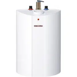
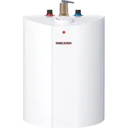
4. General Description
These SHC water heaters can be used in most point-of-use
applications. They are designed to supply hot water for hand
wash and kitchen sinks in a residential, commercial or in-
dustrial environment.
These water heaters can replace traditional hot water sys-
tems which consist of a central hot water heater with hot
water piping going to several draw-off points.
The SHC water heaters are lightweight and compact and
manufactured for easy installation. The units are designed to
be mounted on the wall. These units are designed to operate
under normal street water pressure.
5. Technical Description
The pressure vessel of the water heater is welded glass-
lined steel and is equipped with a sacrificial anode rod. The
thermal insulation is made of polystyrene.
The water heater is equipped with both a thermostat and a
high limit temperature switch. A temperature/pressure relief
valve is supplied with the unit.
ENGLISH
www.stiebel-eltron-usa.com SHC 2.5 / SHC 4 | 5
INSTALLATION
Technical Data
6. Technical Data
SHC 2.5 SHC 4
Item No. 233219 234046
Voltage 110–120 V 110-120 V
Wattage 1300 W 1300 W
Amperage 11.3 A 11.3 A
Phase Single, 1/N/PE Single, 1/N/PE
Frequency 50/60 Hz 50/60 Hz
Type of installation Under sink Under sink
Internal tank material Steel Steel
Enclosure material Plastic Plastic
Thermal insulation material Polystyrene Polystyrene
Color white white
Nominal water volume 2.65 gal 10 l 4 gal 15 l
Standby energy loss
1
0.37 kWh/day 0.39 kWh/day
Recovery time 18 minutes 27 minutes
Temperature setting range 86–140 °F 30–60 °C 86–140 °F 30–60 °C
Maximum operating pressure 150 psi 1.0 MPa 150 psi 1.0 MPa
Weight empty 15.9 lbs 7.2 kg 19.8 lbs 9.0 kg
Weight full 38.6 lbs 17.5 kg 52.9 lbs 24.0 kg
Water connections 1/2˝ NPT 1/2˝ NPT
1
Measured at 131°F / 55°C set point temperature in 68°F / 20°C ambient air temperature.
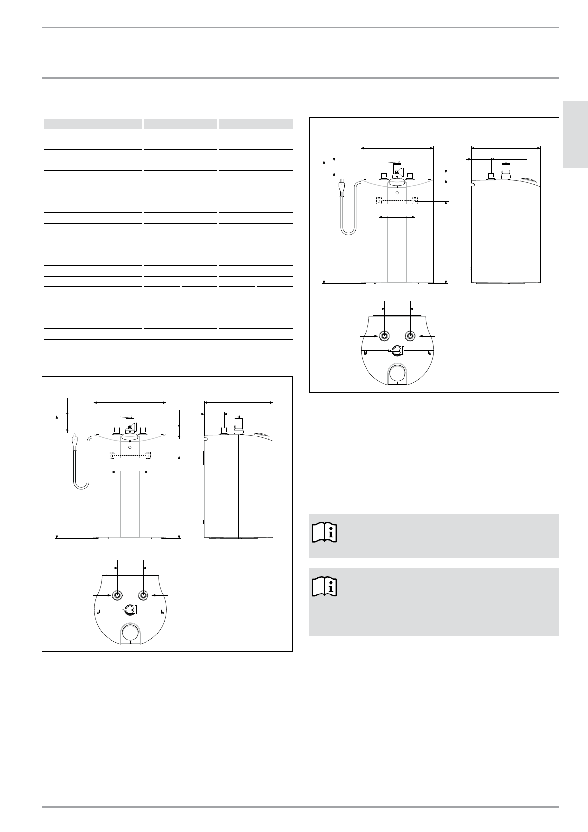
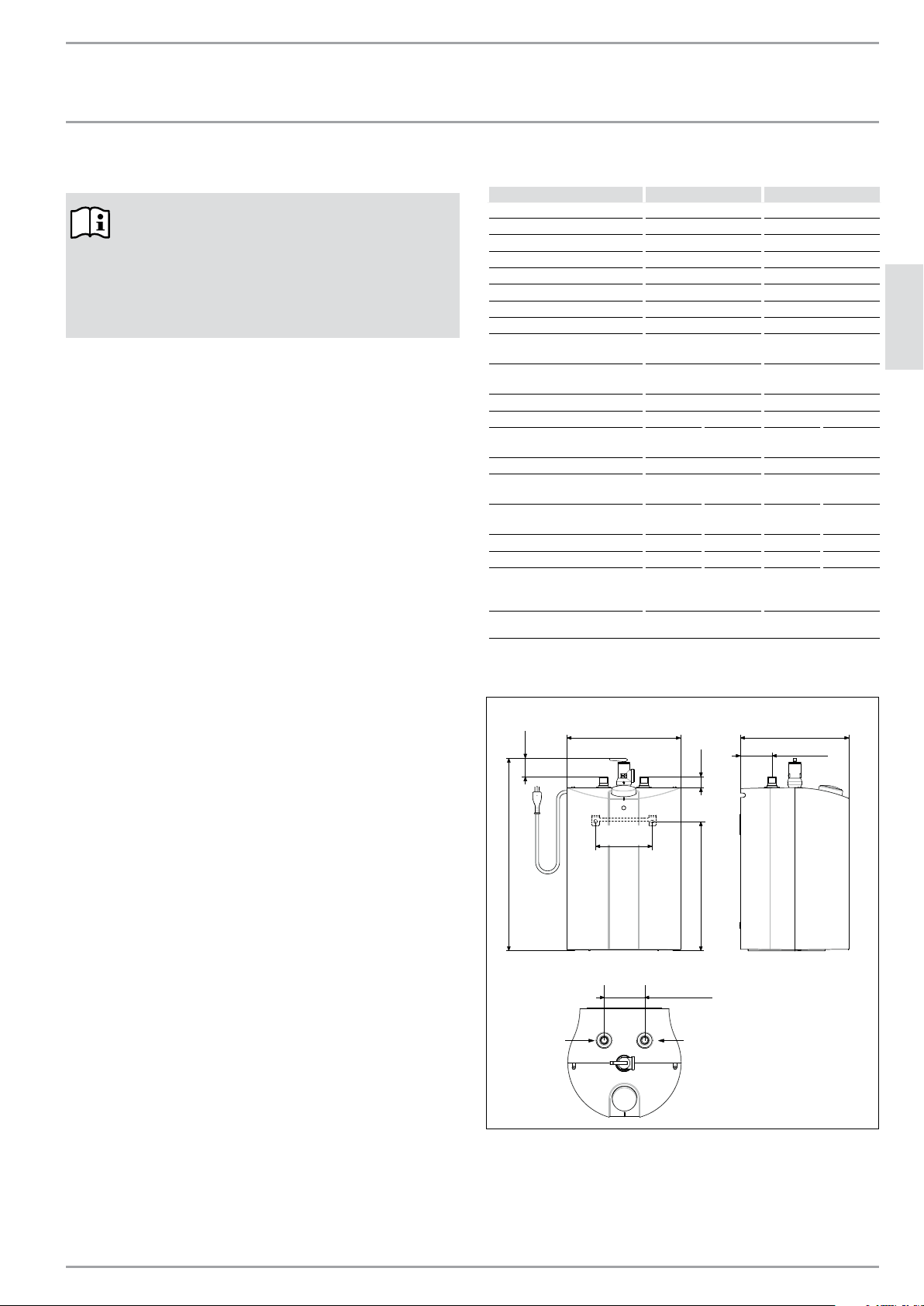
6.1 Dimensions, SHC 2.5
18 11/16″ (475)
1 1/16″ (26.5)12 5/8″ (320)
1 3/4" (45)
3 15/16" (100)
11″ (280)
3 1/8″ (80)
10 5/8″ (270)
5 1/2" (140)
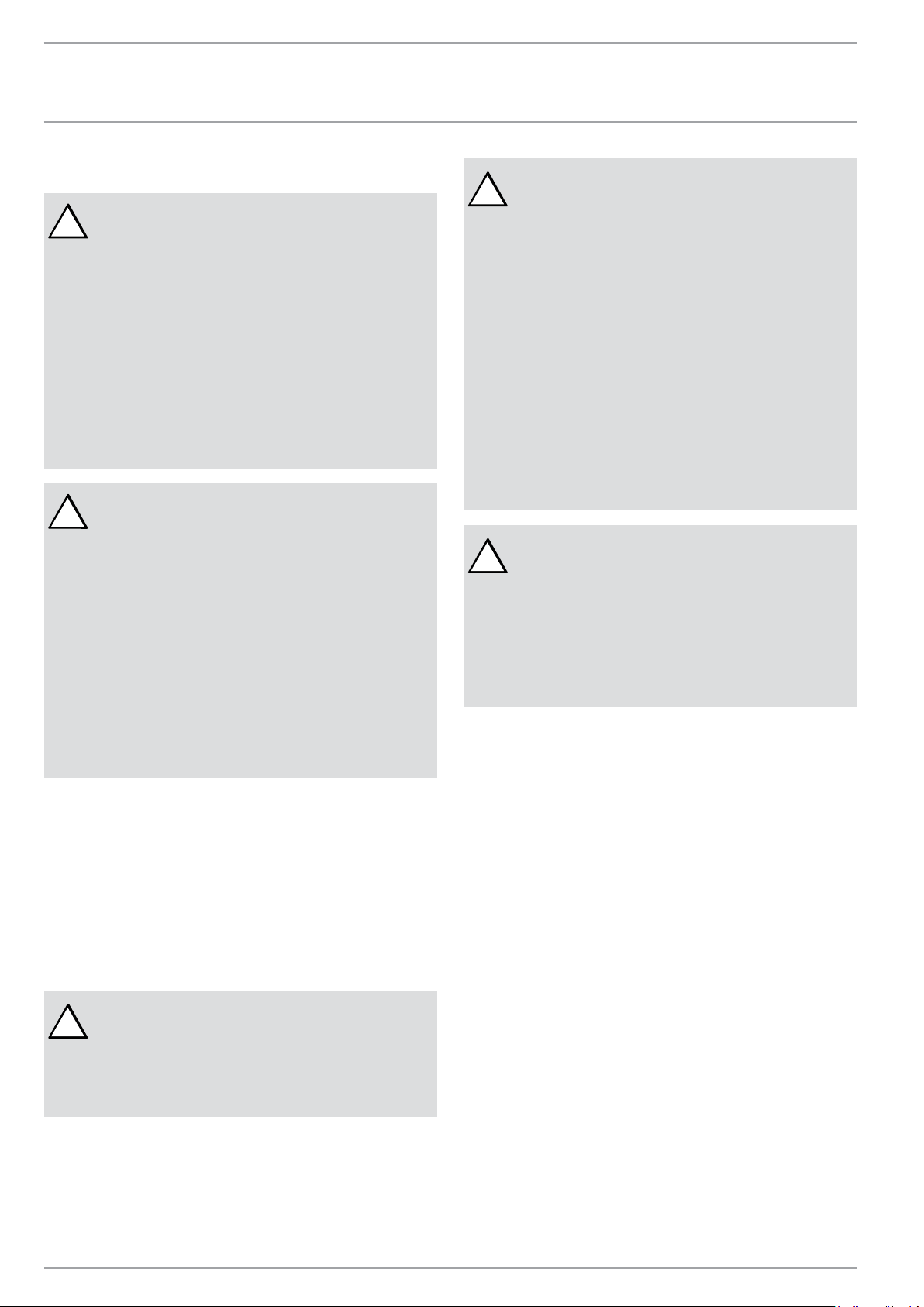
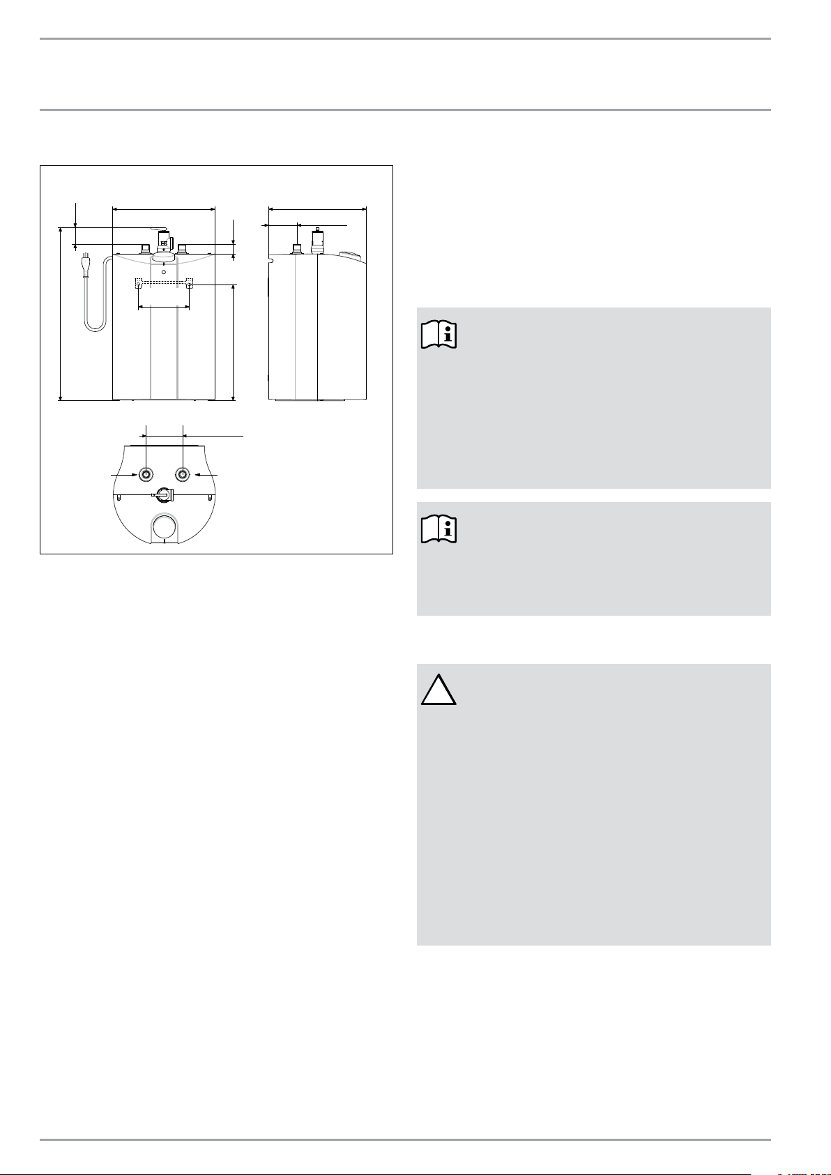
6.2 Dimensions, SHC 4
19 3/4″ (501)
15/16″ (23)13 7/16″ (342)
1 15/16" (49)
3 15/16" (100)
12 5/8″ (320)
3 1/8″ (80)
12 1/2″ (318)
7 7/8" (200)
7. General Recommendations
The installation must be carried out by licensed profession-
als. All state and local codes must be adhered to.
The manufacturer will not be liable for any damages because
of failure to comply with these installation instructions or
because of improper installation performed by an unqual-
ified installer.
NOTE:
The T&P valve must be manually vented monthly.
See 12.2, “Venting the T&P relief valve”, pg. 8
NOTE:
Choose a location that allows easy access for main-
tenance or servicing.
The water heater should be installed with at least
8˝ of clearance on the top and sides of the unit.
in. (mm)
Hot Water
Outlet
1/2″ NPT
male thread
Cold Water
Inlet
1/2″ NPT
male thread
in. (mm)
Hot Water
Outlet
1/2″ NPT
male thread
Cold Water
Inlet
1/2″ NPT
male thread
6 | SHC 2.5 / SHC 4 www.stiebel-eltron-usa.com
INSTALLATION
Mounting the Unit
8. Mounting the Unit
!
NOTICE:
UNIT MUST BE INSTALLED IN A VERTICAL POSITION
WITH THE WATER FITTINGS POINTING UPWARD.
WARNING:
DO NOT INSTALL UNIT WHERE IT WOULD ROUTINE-
LY BE SPLASHED WITH WATER. ELECTRIC SHOCK
MAY RESULT.
CAUTION:
HOT WATER OUTLET PIPES LEAVING UNIT CAN BE
HOT TO THE TOUCH. INSULATION MUST BE USED
FOR HOT WATER PIPES BELOW A HEIGHT OF 36˝
DUE TO BURN RISK TO CHILDREN.
!
NOTICE:
THIS UNIT SHOULD NOT BE INSTALLED IN A LOCA-
TION WHERE IT MAY BE EXPOSED TO FREEZING
TEMPERATURES (LESS THAN 36°F [2°C]). IF THE
UNIT MAY BE SUBJECT TO FREEZING TEMPERA-
TURES, ALL WATER MUST BE DRAINED FROM THE
UNIT. FAILURE TO COMPLY WITH THIS INSTRUCTION
VOIDS ALL WARRANTIES.
THE UNIT SHOULD BE LOCATED IN AN AREA WHERE
WATER LEAKAGE FROM THE UNIT OR CONNECTIONS
WILL NOT RESULT IN DAMAGE TO THE AREA ADJA-
CENT TO THE UNIT. IF SUCH A LOCATION CANNOT
BE AVOIDED IT IS RECOMMENDED THAT A DRAIN
PAN BE INSTALLED UNDER THE UNIT.
1. Drill two (2) 1/4 inch holes in the wall where the
water heater will be mounted.
2. Install plastic wall anchors.
3. Fasten wall mounting bracket to the wall.
4. Hook water heater to the mounting bracket.
5. Pull downwards on the water heater to properly
seat it on the bracket.
9. Plumbing Connections
!
IMPORTANT:
IF WATER PIPES ARE OF COPPER OR BRONZE, USE
DIELECTRIC CONNECTIONS TO PREVENT HEATER
CORROSION. FAILURE TO PROVIDE DIELECTRIC IN-
SULATION MAY RESULT IN PREMATURE TANK OR
NIPPLE FAILURE AND MAY VOID YOUR WARRANTY.
!
NOTICE:
HARD WATER OR WATER WITH A HIGH MINER-
AL COUNT MAY DAMAGE THE UNIT. DAMAGE TO
THE UNIT CAUSED BY SCALE OR A HIGH MINERAL
COUNT IS NOT COVERED UNDER THE WARRANTY.
CAUTION:
TO REDUCE THE RISK OF EXCESSIVE TEMPERATURE
AND PRESSURE IN THE WATER HEATER, A COM-
BINATION TEMPERATURE/PRESSURE (T&P) RELIEF
VALVE HAS BEEN INSTALLED.
CAUTION:
ALWAYS FILL THE UNIT’S TANK WITH WATER BE-
FORE PLUGGING THE WATER HEATER’S CORD INTO
AN ELECTRICAL OUTLET. FAILURE TO DO SO WILL
RESULT IN PERMANENT DAMAGE TO THE WATER
HEATER.
!
NOTICE:
WHEN A WATER HEATER IS INSTALLED IN A
CLOSED WATER-SUPPLY SYSTEM, SUCH AS ONE
HAVING A BACK-FLOW PREVENTER IN THE COLD-
WATER SUPPLY, MEANS SHALL BE PROVIDED TO
CONTROL THERMAL EXPANSION. CONTACT THE
WATER SUPPLIER OR LOCAL PLUMBING INSPECTOR
FOR INFORMATION REGARDING THE CONTROL OF
THIS SITUATION.
Connect the cold water pipe to the cold water connection on
the unit (blue). Connect the hot water pipe to the hot water
connection on the unit (red).
Ensure that the water heater is installed in a level position.
Install a shut-off on the cold water side of the water heater.
This is for emergency shut-off. It must be kept open when
the water heater is operating.
When using copper piping, solder a piece of tubing to a
threaded fitting (union) before screwing the adapter to the
tank.
BRAIDED FLEX HOSE CONNECTORS ARE ALSO RECOMMEND-
ED.
DO NOT APPLY HEAT DIRECTLY TO INLET OR OUTLET CON-
NECTIONS.
A certified T&P valve is mounted to the water heater by the
manufacturer with the outlet oriented to the right. If this
position needs to be changed, leakage may occur, especially
if it will be screwed counter-clockwise, and the T&P valve
may need to be resealed. After all plumbing work has been
completed, the T&P valve needs to be checked for proper
tightness.
During heating, the water volume and water pressure in-
creases in the tank. It is possible for water to leak from the
safety valve, this is normal.
ENGLISH
www.stiebel-eltron-usa.com SHC 2.5 / SHC 4 | 7
INSTALLATION
Electrical Connection
4
3
1
2
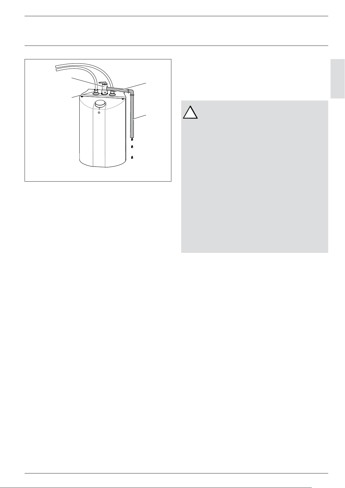
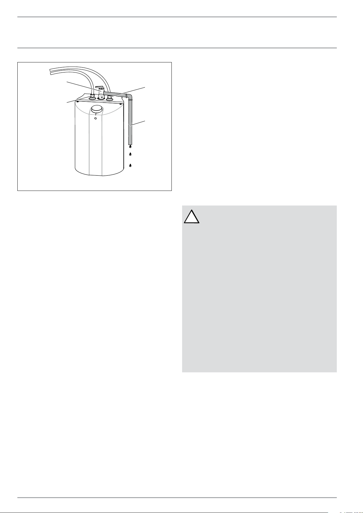
1. Temperature/Pressure relief valve
2. Hot water outlet
3. Cold water inlet
4. Discharge pipe
Install a discharge pipe from the relief valve terminating
at a sink or drain. Orient the tubing so that discharge will
exit within 6˝ (152 mm) above or at any distance below the
structural floor, and cannot contact any live electrical parts.
DO NOT CAP OR THREAD THE END OF THE DISCHARGE PIPE,
IT MUST BE UNOBSTRUCTED AND FULL SIZE.
The T&P valve is certified by a nationally recognized test
laboratory that maintains periodic inspection of the listed
equipment, and meets the requirements for relief valves and
automatic shut-off devices for hot water supply systems ANSI
Z21.22.
The T&P valve is marked with a maximum pressure, which
does not exceed the maximum working pressure of the water
heater (150 PSI).
THE DISCHARGE PIPE
- Must not be smaller in size than the outlet pipe size of
the valve, or have reducing couplings.
- Must not be plugged or blocked.
- Must be of material suitable for hot water.
- Must not be over fifteen feet (15
´
) in length.
- Must not have more than two elbows.
- Must terminate at an adequate drain.
- Must not have a valve between the relief valve and the
tank.
9.1 Filling the Water Heater
To fill the water heater:
1. Open the hot water faucet.
2. Open the cold water supply valve.
3. When water runs out of the faucet, the tank is filled.
4. Close the hot water faucet.
5. Manually vent the T&P valve. See 12.2, “Venting the
T&P relief valve”, pg. 8
6. Check entire system for leaks.
10. Electrical Connection
!
CAUTION:
ALWAYS FILL THE UNIT’S TANK WITH WATER BE-
FORE PLUGGING THE WATER HEATER’S CORD INTO
AN ELECTRICAL OUTLET. FAILURE TO DO SO WILL
RESULT IN PERMANENT DAMAGE TO THE WATER
HEATER.
NOTICE:
THE WATER HEATER MUST BE CONNECTED TO A
GROUNDED OUTLET.
THIS WATER HEATER WAS DESIGNED FOR USE AT
110 - 120V. DO NOT USE THIS WATER HEATER WITH
ANY OTHER VOLTAGE. FAILURE TO USE THE COR-
RECT VOLTAGE MAY RESULT IN PERSONAL INJURY
OR PROPERTY DAMAGE.
THE HEATER IS SUPPLIED WITH AN ELECTRICAL
CABLE WITH A PLUG. IF THE CABLE IS DAMAGED OR
LENGTH NOT SUFFICIENT, IT MUST BE REPLACED BY
A LICENSED ELECTRICIAN.
To be certain that all the air is out of the system, open the
hot water faucet on your fixtures until constant water flows
from them. Otherwise, damage to the device may occur.
Connect the water heater to a GROUNDED OUTLET.
The unit is fitted with a power cord to connect the water
heater to a receptacle. State and local codes must be adhered
to. Install the correct breaker at the circuit breaker panel.
The water heater was manufactured and wired in accordance
with the UL requirements.
A temperature high limit with manual reset has been facto-
ry installed to interrupt the power supply in the event of a
thermostat failure.
DO NOT use this water heater with any other voltage. Failure
to use the correct voltage may result in personal injury or
property damage.
8 | SHC 2.5 / SHC 4 www.stiebel-eltron-usa.com
INSTALLATION
Settings
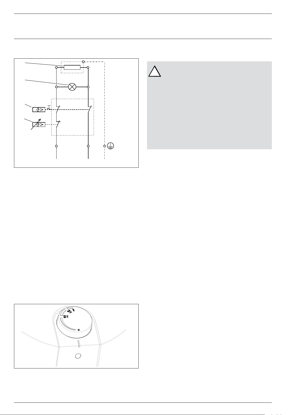
10.1 Electrical diagram
L
A B
N PE
1 2
D0000035810
4
5
3
2
1
1. Heating element
2. Lamp indicator
3. Cut-off
4. Thermostat
5. Tank
11. Settings
The water heater is equipped with an adjustable thermostat
that automatically controls the water temperature. The indi-
cator lamp remains lit only when the water is being heated.
The temperature is adjusted by turning the knob counter-
clockwise (to the left) to increase the temperature and clock-
wise (to the right) to decrease the temperature.
The water heater thermostat can be set to guard against
freezing. This position keeps the internal temperature above
the freezing point.
The piping outside of the water heater and the faucet are not
protected against freezing.
Freeze protection setting
D0000034989
Temperature setting
The water heater thermostat is factory set at 120°F (49°C).
12. Maintenance Instructions
!
WARNING:
BEFORE SERVICING OR CLEANING THE WATER
HEATER, DISCONNECT THE WATER HEATER FROM
THE ELECTRICAL OUTLET.
THE TEMPERATURE/PRESSURE RELIEF VALVE
MUST BE MANUALLY OPERATED ONCE PER MONTH.
CAUTION SHOULD BE TAKEN TO ENSURE THAT:
1. NO ONE IS NEAR THE TEMPERATURE/PRESSURE
RELIEF VALVE DISCHARGE PIPE.
2. THE WATER DISCHARGED WILL NOT CAUSE
ANY BODILY INJURY OR PROPERTY DAMAGE. THE
WATER MAY BE EXTREMELY HOT.
Do not attempt to repair the water heater.
Call your licensed plumber or electrician for service. Unplug
the unit whenever the water supply is turned off.
Before calling for service, make sure that:
1. The heater is properly filled.
2. The electrical supply has not been interrupted.
12.1 Descaling the heating element
Approximately every two years, it is advisable to descale the
heating element and to check the condition of the magne-
sium anode, replacing it if the diameter is less than 5/16˝ (8
mm). (See 12.8, “Changing the anode rod”, pg. 10).
12.2 Venting the T&P relief valve
The temperature/pressure relief valve must be manually op-
erated once per month. Caution should be taken to ensure
that:
1. No one is near the temperature/pressure relief valve
discharge pipe.
2. The water discharged will not cause any bodily inju-
ry or property damage. The water may be extreme-
ly hot.
12.2.1 T&P venting / testing procedure
1. Before venting, make sure it is known how to shut
off the water supply to the heater. It is not necessary
initially, but may become so if the T&P valve does
not reseat properly when vented, which may cause
water to leak.
2. On the top of the T&P valve is a small handle that
lifts a pin in the center of the valve. Lift the handle
up so the valve opens, then release it so it closes.
This will vent the T&P valve and at the same time
test if it is functioning correctly.
3. If the valve is stuck so that it does not open or does
not close it should be replaced immediately.

ENGLISH
www.stiebel-eltron-usa.com SHC 2.5 / SHC 4 | 9
INSTALLATION
Maintenance Instructions
4. The T&P valve may take more than one attempt to
reseat correctly. If this is the case, try re-opening
the valve and quickly releasing it, allowing it to slap
shut. This action does not damage the valve.
5. If after repeated attempts the valve does not reseat
properly and continues to leak water, it should be
replaced. If the valve fails this test it was already
malfunctioning and was not offering the protection
needed.
6. Immediately close the cold water inlet to the heater.
Replace the malfunctioning T&P valve with a new
one.
Failure to install and maintain a properly functioning and
properly listed temperature/pressure relief valve will release
the manufacturer and distributor of this water heater from
any claim which might result from excessive temperature
or pressure. Regular venting/testing may increase the life
of the valve.
12.3 Draining the water heater
Some service work requires draining the water heater. This
should be done in the following manner:
1. Unplug the water heater.
2. Open the hot water faucet to let the hot water out.
Let it continue to flow until cold water runs from the
faucet.
3. Turn off the cold water supply to the heater.
4. Close the hot water faucet
5. Disconnect the heater from both the hot and cold
water pipes.
6. Carefully detach the water heater from the wall.
7. Tilt the water heater to drain out the remaining
water.
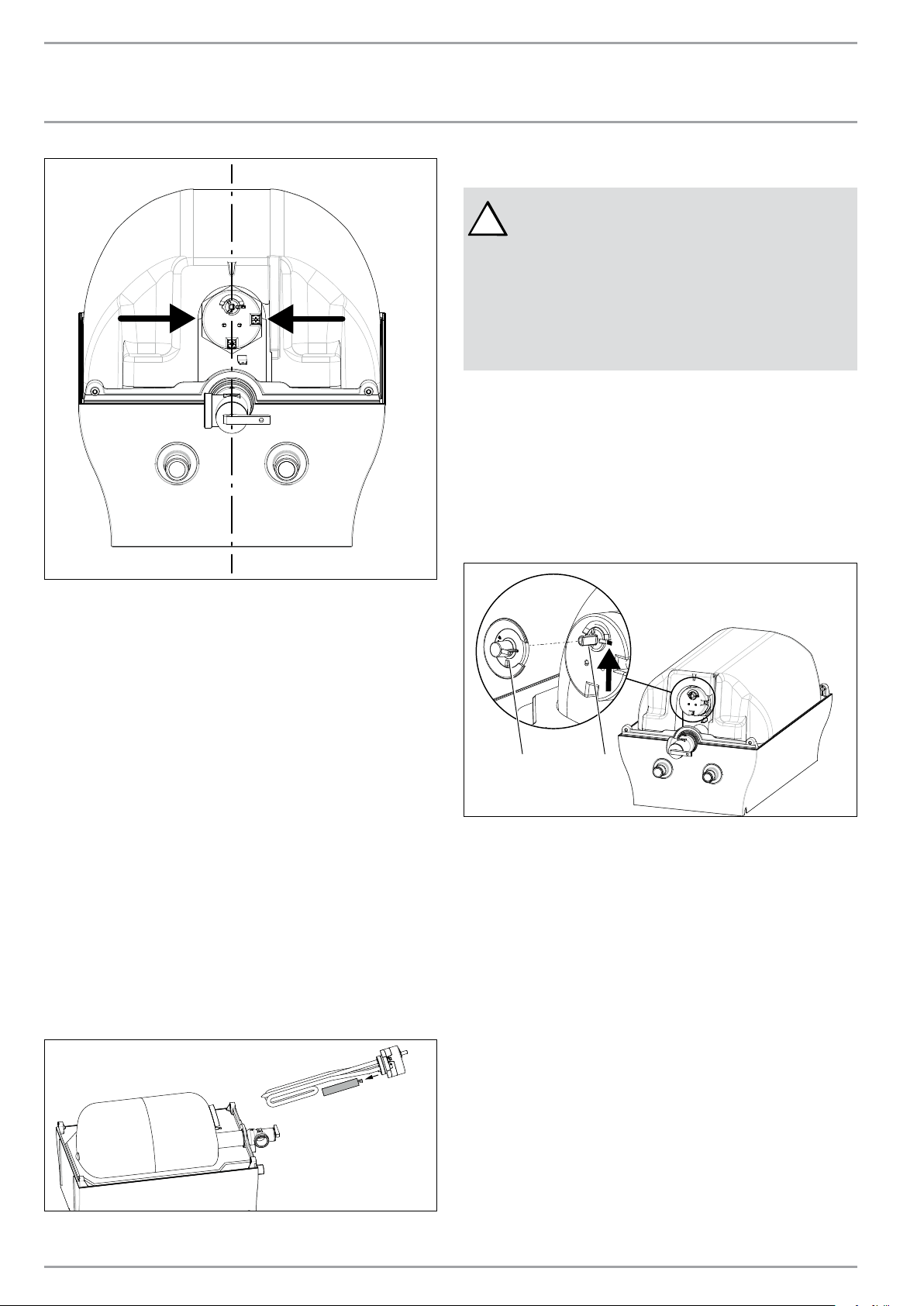
12.4 Removing the cover
1. Remove the temperature control knob from the top
of the unit.
2. Remove the screws from the cover.
3. Remove the cover by tilting the bottom side and lift-
ing off the cover. Cover should come right off.
D0000034990
12.5 Removing the heating element
1. Unplug and drain the water heater (See 12.3,
“Draining the water heater”, pg. 9).
2. Remove the cover (See 12.4, “Removing the cover”,
pg. 9).
3. Disconnect the line wires from the thermostat.
4. Remove the thermostat from the heating element.
5. Using a suitable wrench, unscrew the heating
element.
6. Remove the heating element from the tank.
D0000034991
12.6 De-scaling the heating element
Scale deposit can affect the heating capacity of the heating
element. Scale can even cause the element to burn out. The
element can be descaled either chemically or manually.
1. Remove the heating element (See 12.5, “Removing
the heating element”, pg. 9).
2. To descale chemically, soak the heating element in
white vinegar or other descaling solution, then rinse
well.
3. To descale manually, use a nonmetallic (soft) tool;
brush the crust off the element. Make sure you do
not damage the surface of the heating element.
4. Reinstall the heating element.
5. Refill the water heater with water and check for
leaks before connecting the power.
12.7 Replacing the heating element
1. Unplug and drain the water heater (See 12.3,
“Draining the water heater”, pg. 9).
2. Remove the cover (See 12.4, “Removing the cover”,
pg. 9).
3. Remove the heating element (See 12.5, “Removing
the heating element”, pg. 9).
4. Install and seal the new element. Make sure that the
heating element is positioned correctly.
5. Remount all the line wires to their original location.
6. Refill the water heater with water and check for
leaks before connecting the power.
10 | SHC 2.5 / SHC 4 www.stiebel-eltron-usa.com
INSTALLATION
Maintenance Instructions
D0000036026
12.8 Changing the anode rod
A magnesium anode is used to extend the life of the tank.
Permanent removal of this anode for any reason will void
the warranty.
Depending on conditions, the magnesium anode rod may
need to be changed approximately every two years. Galvanic
and electrolytic corrosion can destroy a tank with a spent
anode rod. Rusty water is usually an indicator of a spent
anode rod.
1. Unplug and drain the water heater (See 12.3,
“Draining the water heater”, pg. 9).
2. Remove the cover (See 12.4, “Removing the cover”,
pg. 9).
3. Remove the heating element (See 12.5, “Removing
the heating element”, pg. 9).
4. Remove the anode rod from the dismounted heating
element holder by unscrewing.
5. Fit a new anode rod into the heating element
holder.
6. Refit all the wires and the heating element.
7. Refill the water heater with water and check for
leaks before connecting the power.
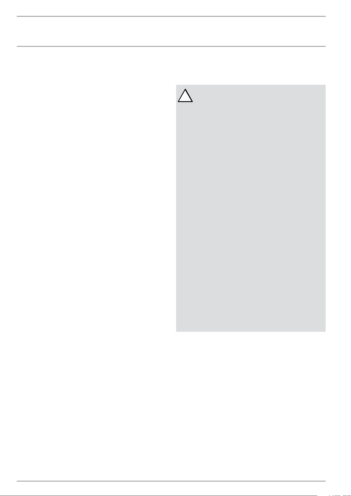
D0000034992
12.9 Safety Shut-off
!
WARNING:
NEVER LOCK THE SLIDING RESET PLUNGER.
DANGER:
WATER TEMPERATURES OVER 125°F (52 °C) CAN
CAUSE SEVERE BURNS INSTANTLY OR DEATH FROM
SCALDING. DO NOT ATTEMPT TO RESET THE HIGH
LIMIT SWITCH WITHOUT FIRST COOLING DOWN THE
WATER INSIDE THE WATER HEATER.
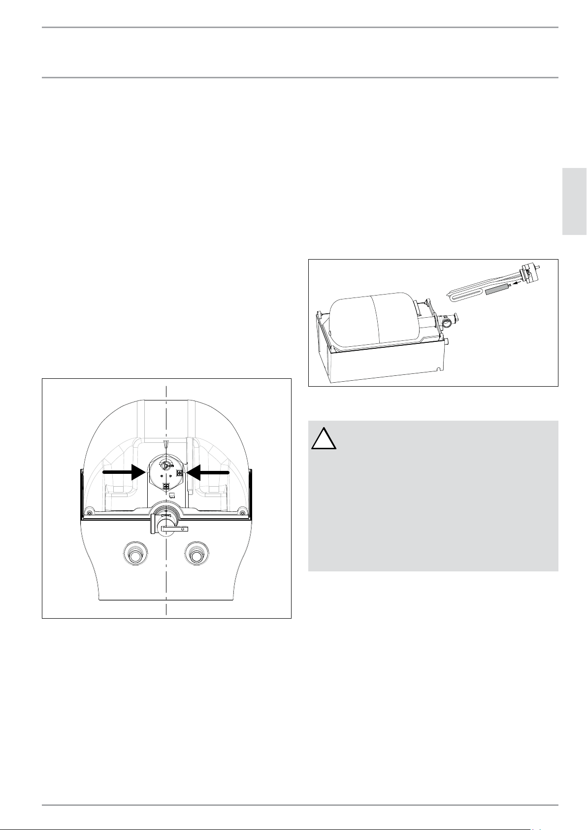
12.9.1 Resetting high temperature shut-off system
1. Unplug the water heater.
2. Remove the cover (See 12.4, “Removing the cover”,
pg. 9).
3. Unplug the adapter (1) from the controller shaft.
4. Press in button (2) with an appropriate tool.
5. Reassemble the adapter in the correct position.
6. Reassemble the cover of the heater and tighten.
7. Reassemble the thermostat control knob.
1 2
1. Adapter
2. Button

ENGLISH
www.stiebel-eltron-usa.com SHC 2.5 / SHC 4 | 11
WARRANTY
Limited Warranty
This Warranty is valid for U.S.A. & Canada only. Warranties
may vary by country. Please consult your local Stiebel Eltron
Representative for the Warranty for your country.
13. Limited Warranty
Subject to the terms and conditions set forth in this limited warranty, Stiebel Eltron, Inc. (the “Manufacturer”) hereby
warrants to the original purchaser (the “Owner”) that each Mini-Tank Domestic Hot Water Heater (the “Heater”) shall
not (i) leak due to defects in the Manufacturer’s materials or workmanship for a period of six (6) years from the date
of purchase or (ii) fail due to defects in the Manufacturer’s materials or workmanship for a period of two (2) years
from the date of purchase. As Owner’s sole and exclusive remedy for breach of the above warranty, Manufacturer
shall, at the Manufacturer’s discretion, send replacement parts for local repair; retrieve the unit for factory repair, or
replace the defective Heater with a replacement unit with comparable operating features. Manufacturer’s maximum
liability under all circumstances shall be limited to the Owner’s purchase price for the Heater.
This limited warranty shall be the exclusive warranty made by the Manufacturer and is made in lieu of all other
warranties, express or implied, whether written or oral, including, but not limited to warranties of merchantability
and fitness for a particular purpose. Manufacturer shall not be liable for incidental, consequential or contingent
damages or expenses arising directly or indirectly from any defect in the Heater or the use of the Heater.
Manufacturer shall not be liable for any water damage or other damage to property of Owner arising, directly or
indirectly, from any defect in the Heater or the use of the Heater. Manufacturer alone is authorized to make all
warranties on Manufacturer’s behalf and no statement, warranty or guarantee made by any other party shall be
binding on Manufacturer.
Manufacturer shall not be liable for any damage whatsoever relating to or caused by:
1. any misuse or neglect of the Heater, any accident to the Heater, any alteration of the Heater, or any other
unintended use;
2. acts of God and circumstances over which Manufacturer has no control;
3. installation of the Heater other than as directed by Manufacturer and other than in accordance with applicable
building codes;
4. failure to maintain the Heater or to operate the Heater in accordance with the Manufacturer’s specifications;
5. operation of the Heater under fluctuating or excessive water pressure or in the event the Heater is supplied with
non-potable water, for any duration;
6. improper installation and/or improper materials used by any installer and not relating to defects in parts or
workmanship of Manufacturer;
7. moving the Heater from its original place of installation;
8. exposure to freezing conditions;
9. water quality issues such as corrosive water, hard water, and water contaminated with pollutants or additives;
10. not continuously supplying the unit with water aka “dry-firing”.
Should owner wish to return the Heater to manufacturer for repair or replacement under this warranty, Owner
must first secure written authorization from Manufacturer. Owner shall demonstrate proof of purchase, including
a purchase date, and shall be responsible for all removal and transportation costs. If Owner cannot demonstrate a
purchase date this warranty shall be limited to the period beginning from the date of manufacture stamped on the
Heater. Manufacturer reserves the right to deny warranty coverage upon Manufacturer’s examination of the Heater.
This warranty is restricted to the Owner and cannot be assigned.
Some States and Provinces do not allow the exclusion or limitation of certain warranties. In such cases, the limitations
set forth herein may not apply to the Owner. In such cases this warranty shall be limited to the shortest period and
lowest damage amounts allowed by law. This warranty gives you specific legal rights and you may also have other
rights which vary from State to State or Province to Province.
Owner shall be responsible for all labor and other charges incurred in the removal or repair of the Heater in the field.
Please also note that the Heater must be installed in such a manner that if any leak does occur, the flow of water from
any leak will not damage the area in which it is installed.
STIEBEL ELTRON, Inc.
17 West Street
West Hatfield, MA 01088, USA
Phone: 800.582.8423 or 413.247.3380
Fax: 413.247.3369
Email: info
@
stiebel-eltron-usa.com
www.stiebel-eltron-usa.com
12 | SHC 2.5 / SHC 4 www.stiebel-eltron-usa.com
ÍNDICE | FUNCIONAMIENTO | INSTALACIÓN
1. Información general ��������������������������������� 13
2. Advertencias de seguridad ���������������������������14
3. Registre su producto �������������������������������� 15
4. Descripción general ���������������������������������� 15
5. Descripción técnica ���������������������������������� 15
6. Datos técnicos ���������������������������������������� 15
6.1 Dimensiones, SHC 2.5 ������������������������������������15
6.2 Dimensiones, SHC 4 ��������������������������������������16
7. Recomendaciones generales �������������������������16
8. Cómo montar la unidad ������������������������������16
9. Conexiones de plomería ������������������������������ 17
9.1 Cómo llenar el calentador de agua ������������������ 18
10. Conexión eléctrica ����������������������������������� 18
10.1 Diagrama eléctrico ���������������������������������������19
11. Configuraciones _______________________________________19
12. Instrucciones de mantenimiento ____________________19
12.1 Eliminar el sarro del elemento calefactor ������������19
12.2 Ventilación manual de la válvula de descarga de
P y T ���������������������������������������������������������19
12.3 Cómo vaciar el calentador de agua ������������������ 20
12.4 Cómo remover la cubierta ����������������������������� 20
12.5 Cómo remover el elemento calefactor ��������������� 20
12.6 Cómo remover el sarro del elemento calefactor ��� 20
12.7 Cómo reemplazar el elemento calefactor �����������21
12.8 Cómo cambiar el ánodo ���������������������������������21
12.9 Apagado de seguridad �����������������������������������21
13. Garantía Limitada ____________________________________ 23
INSTRUCCIONES DE SEGURIDAD
IMPORTANTES
!
ADVERTENCIA:
AL UTILIZAR APARATOS ELÉCTRICOS, PARA REDU-
CIR EL RIESGO DE INCENDIO, DESCARGA ELÉCTRI-
CA O LESIONES A PERSONAS, DEBE RESPETAR LAS
MEDIDAS BÁSICAS DE SEGURIDAD, A SABER:
1. LEA TODAS LAS INSTRUCCIONES ANTES DE UTILIZAR
EL CALENTADOR DE AGUA.
2. Este calentador de agua debe estar puesto a tierra.
Conéctelo únicamente a un tomacorriente que tenga
una apropiada puesta a tierra. Vea las las instruccio-
nes especiales de puesta a tierra en el capítulo 10,
“Conexión eléctrica”, pág. 18.
3. Instale o ubique este calentador de agua únicamen-
te de acuerdo con las instrucciones de instalación
suministradas.
4. Este calentador de agua solamente debe tener el uso
previsto que se describe en este manual.
5. No utilice un cable alargador para este calentador
de agua. Si Ud. no cuenta con ningún receptáculo
eléctrico cercano al calentador de agua, contacte a
un electricista calificado para instalar un receptáculo
correctamente.
6. Como con cualquier otro aparato, es necesario
supervisar de cerca a los niños si estos utilizan el
aparato.
7. No haga funcionar este calentador de agua si tiene
un cable o enchufe dañado, si no funciona correcta-
mente o si ha sido dañado o se ha caído.
8. Solo el personal de servicio técnico calificado debe
realizar el mantenimiento de este calentador de
agua. Comuníquese con el personal matriculado más
cercano para la inspección, reparación o ajuste de la
unidad.
CONSERVE ESTAS
INSTRUCCIONES
FUNCIONAMIENTO
Información general
ESPAÑOL
www.stiebel-eltron-usa.com SHC 2.5 / SHC 4 | 13
1. Información general
!
PRECAUCIÓN:
PARA REDUCIR EL RIESGO DE TEMPERATURA Y
PRESIÓN EXCESIVAS EN EL CALENTADOR DE AGUA,
INSTALE EL EQUIPO DE PROTECCIÓN DE TEMPERA-
TURA Y PRESIÓN EXIGIDO POR LOS CÓDIGOS LOCA-
LES Y UNA VÁLVULA DE DESCARGA COMBINADA DE
TEMPERATURA Y PRESIÓN CERTIFICADA POR UN
LABORATORIO DE ANÁLISIS RECONOCIDO A NIVEL
NACIONAL QUE REALICE INSPECCIONES PERIÓDI-
CAS DE LA PRODUCCIÓN DE LOS EQUIPOS O MATE-
RIALES MENCIONADOS Y CUMPLA LOS REQUISITOS
PARA VÁLVULAS DE DESCARGA Y DISPOSITIVOS
DE APAGADO AUTOMÁTICO PARA SUMINISTRO
DE AGUA CALIENTE ANSI Z21.22. ESTA VÁLVULA
TIENE UNA MARCA DE PRESIÓN MÁXIMA, LA CUAL
NO EXCEDE LA PRESIÓN OPERATIVA MÁXIMA DEL
CALENTADOR DE AGUA. INSTALE LA VÁLVULA EN
LA ABERTURA SUMINISTRADA Y MARCADA PARA
ESTE FIN EN EL CALENTADOR DE AGUA Y ORIENTE
LA TUBERÍA DE MODO QUE LA DESCARGA DE LA
VÁLVULA SALGA DENTRO DE LAS 6˝ POR ARRIBA
O A CUALQUIER DISTANCIA POR DEBAJO DEL SUELO
ESTRUCTURAL. NO DEBE HACER CONTACTO CON
NINGUNA PARTE CONECTADA A LA CORRIENTE
ELÉCTRICA. LA ABERTURA DE DESCARGA NO SE
DEBE BLOQUEAR O REDUCIR EN NINGUNA CIR-
CUNSTANCIA.
Lea este manual completamente. El incumplimiento de todas
las guías, instrucciones y normas puede causar lesiones per-
sonales o daños materiales. Todo uso, servicio, alteración,
ajuste e instalación inapropiados puede provocar graves
lesiones o daños.
Esta unidad debe ser instalada por un electricista y plo-
mero matriculado. La instalación debe cumplir con todos
los códigos de plomería y electricidad locales, del estado y
de la nación. Es responsabilidad del instalador realizar una
instalación apropiada. El incumplimiento de las instrucciones
de instalación y funcionamiento o el uso inapropiado anulan
la garantía.
Conserve estas instrucciones para futuras consultas. El ins-
talador deberá dejarle estas instrucciones al consumidor.
Si tiene preguntas acerca de la instalación, el uso o el fun-
cionamiento de este calentador de agua, o si necesita ma-
nuales adicionales de instalación, comuníquese con nuestra
línea de servicio técnico: 800-582-8423 (solo para EE. UU. y
Canadá). Si Ud. se comunica desde el exterior de los EE. UU.
o de Canadá, marque USA 413-247-3380. Lo pondremos en
contacto con un representante de servicio técnico calificado
de Stiebel Eltron en su zona.
1. No ubique el calentador de agua en lugares donde las
tuberías de agua puedan estar sujetas a temperaturas
muy bajas.
2. Se recomienda contar con una rejilla de desagüe cerca
de la unidad para que la unidad desagüe fácilmente si
es necesario.
3. En la instalación del calentador de agua, debe asegu-
rarse de que, en caso de pérdida de agua, el agua que
se pierda no provoque daños en el área que rodea al
calentador de agua. Bajo ninguna condición el fabri-
cante se responsabilizará por los daños causados por
el agua en relación con este calentador de agua.
4. Cuando instale el calentador de agua, debe asegurarse
de que haya suficiente espacio libre alrededor de la
unidad para facilitar su mantenimiento y servicio.
!
ESTE ES EL SÍMBOLO DE ALERTA DE SEGURI-
DAD.
SE UTILIZA PARA AVISAR SOBRE PELIGROS PO-
TENCIALES DE LESIONES PERSONALES. RESPETE
TODOS LOS MENSAJES DE SEGURIDAD CON ESTE
SÍMBOLO PARA EVITAR UNA POSIBLE LESIÓN O
MUERTE.
FUNCIONAMIENTO
Advertencias de seguridad
14 | SHC 2.5 / SHC 4 www.stiebel-eltron-usa.com
2. Advertencias de seguridad
!
LEA Y SIGA ESTAS INSTRUCCIONES.
EL INCUMPLIMIENTO DE ESTAS INSTRUCCIONES
PUEDE CAUSAR LESIONES FÍSICAS GRAVES O LA
MUERTE.
LA UNIDAD DEBE SER INSTALADA POR UN PLOME-
RO MATRICULADO. LA INSTALACIÓN DEBE CUMPLIR
CON TODOS LOS CÓDIGOS DE PLOMERÍA Y ELEC-
TRICIDAD LOCALES, DEL ESTADO Y DE LA NACIÓN.
EL MANTENIMIENTO O REPARACIÓN DE LA UNIDAD
DEBE SER REALIZADO POR UNA AGENCIA DE SER-
VICIO CALIFICADO.
ANTES DE REALIZAR LA INSTALACIÓN, EL AJUSTE,
LA ALTERACIÓN O EL SERVICIO TÉCNICO DE ESTA
UNIDAD, ES NECESARIO DESENCHUFAR EL CABLE
DE ELECTRICIDAD. NO HACERLO PUEDE PROVOCAR
LESIONES PERSONALES GRAVES O LA MUERTE.
NUNCA QUITE LA CUBIERTA DE LA UNIDAD, A
MENOS QUE LA ELECTRICIDAD QUE ALIMENTA LA
UNIDAD ESTÉ CORTADA. NO HACERLO PUEDE PRO-
VOCAR LESIONES PERSONALES O LA MUERTE.
NO ALMACENE NI USE GASOLINA NI NINGÚN OTRO
VAPOR O LÍQUIDO INFLAMABLE CERCA DE ESTE O
DE OTRO APARATO.
!
PELIGRO:
LAS TEMPERATURAS DE AGUA SUPERIORES A LOS
125 °F (52 °C) PUEDEN CAUSAR QUEMADURAS
GRAVES DE MANERA INSTANTÁNEA O LA MUERTE
POR QUEMADURAS. HAY UN RIESGO POTENCIAL
DE QUEMADURAS CON AGUA CALIENTE SI EL TER-
MOSTATO DE LA UNIDAD ESTÁ CONFIGURADO DE-
MASIADO ELEVADO. EN LOS HOGARES DONDE HAY
NIÑOS PEQUEÑOS, PERSONAS DISCAPACITADAS O
PERSONAS MAYORES, PROBABLEMENTE SE RE-
QUIERA QUE EL TERMOSTATO SE CONFIGURE A 120
°F (49 °C) O A UNA TEMPERATURA MENOR PARA
EVITAR POSIBLES LESIONES POR AGUA CALIENTE.
!
ADVERTENCIA:
ESTE CALENTADOR DE AGUA DEBE SER INSTALA-
DO ESTRICTAMENTE SEGÚN LAS INSTRUCCIONES
ADJUNTAS Y LOS CÓDIGOS DE ELECTRICIDAD Y
EDIFICACIÓN LOCALES. ADEMÁS, ES POSIBLE QUE
LAS CONEXIONES CON EL CALENTADOR DE AGUA
PROVOQUEN PÉRDIDAS DE AGUA. POR LO TANTO,
ES NECESARIO QUE LA INSTALACIÓN DEL CALENTA-
DOR DE AGUA PERMITA QUE EL AGUA QUE CAIGA
SE DIRIJA A UNA REJILLA DE DESAGÜE APROPIADA,
DE MODO QUE EL AGUA NO PRODUZCA DAÑOS AL
EDIFICIO, LOS MUEBLES, LAS ALFOMBRAS O CUAL-
QUIER OTRA PERTENENCIA. NI EL FABRICANTE NI
EL DISTRIBUIDOR SE RESPONSABILIZARÁN POR
LOS DAÑOS CAUSADOS POR EL AGUA QUE SALE DEL
CALENTADOR DE AGUA, LA VÁLVULA DE DESCARGA
DE PRESIÓN DE LA TEMPERATURA O LOS ELEMEN-
TOS RELACIONADOS SI NO SE HA PROVISTO UN
DESAGÜE APROPIADO PARA EL AGUA.
!
PRECAUCIÓN:
EL GAS HIDRÓGENO PUEDE PRODUCIRSE EN UN
SISTEMA DE AGUA CALIENTE PROPORCIONADO POR
ESTE CALENTADOR SI ESTE CALENTADOR NO SE HA
UTILIZADO POR UN LARGO PERÍODO DE TIEMPO
(EN GENERAL, 2 SEMANAS O MÁS). EL HIDRÓGENO
ES UN GAS EXTREMADAMENTE INFLAMABLE.
PARA EVITAR EL RIESGO DE LESIONES EN ESTAS
CONDICIONES, SE RECOMIENDA ABRIR LA LLAVE
DE AGUA CALIENTE DE LA PILETA DE LA COCINA
DURANTE VARIOS MINUTOS ANTES DE UTILIZAR
CUALQUIER APARATO ELÉCTRICO CONECTADO AL
SISTEMA DE AGUA CALIENTE.
CUANDO HAY HIDRÓGENO PRESENTE, PROBABLE-
MENTE HABRÁ UN SONIDO INUSUAL, COMO EL
AIRE QUE ESCAPA POR LA TUBERÍA CUANDO EL
AGUA COMIENZA A CORRER. NO SE DEBE FUMAR
NI DEJAR NINGUNA HORNALLA PRENDIDA CERCA
DE LA PILETA CUANDO LA LLAVE DE AGUA ESTÉ
ABIERTA.
VENTILACIÓN MANUAL MENSUAL DE LA VÁLVULA
DE DESCARGA DE P Y T REDUCIRÁ ESTE EFECTO.
VEA 1, “ANTES DE VENTILACIÓN, ASEGÚRESE DE
QUE SE CONOCE LA FORMA DE CORTAR EL SUMI-
NISTRO DE AGUA AL CALENTADOR. NO ES NECE-
SARIO INICIALMENTE, PERO PUEDE LLEGAR A SER
DE MODO QUE SI LA VÁLVULA P Y T NO VUELVA A
ASENTAR CORRECTAMENTE CUANDO VENTILADO,
LO QUE PUEDE CAUSAR QUE EL AGUA SE ESCAPE.”,
PÁG. 20
FUNCIONAMIENTO
Registre su producto
ESPAÑOL
www.stiebel-eltron-usa.com SHC 2.5 / SHC 4 | 15
3. Registre su producto
NOTA:
Debe registrar este producto en un plazo de 90
días desde la compra a través de nuestra página
web para activar cualquier garantía estándar o
para optar a la ampliación de la garantía. Visite
nuestra página web www.stiebel-eltron-usa.com
y haga clic en “Registre su producto”.
Antes de comenzar el proceso de registro, le sugerimos
que recopile la siguiente información que necesitará:
Modelo; ejemplo: SHC 2.5 (tomado de la etiqueta situada
en la parte superior de la unidad, en el centro)
Número que se indica después de “Nr.”
Lugar de compra
Fecha de compra
Nombre y apellido
Dirección de email
Dirección postal
Número de teléfono
Si tiene alguna pregunta en relación con el proceso de
registro o con las opciones de garantía, por favor, pónga-
se en contacto directamente con Stiebel Eltron USA en el
número de teléfono (800)-582-8423.
4. Descripción general
Estos calentadores de agua SHC pueden utilizarse en la ma-
yoría de las aplicaciones en el punto de uso. Están diseñados
para proporcionar agua caliente para el lavado de manos y
para las piletas de cocina en el ámbito hogareño, comercial
o industrial.
Estos calentadores de agua pueden reemplazar a los sis-
temas tradicionales de agua caliente que consisten en un
calentador central de agua con una tubería de agua caliente
dirigida a varios puntos de drenaje.
Los calentadores de agua SHC son livianos y compactos, y
están fabricados de modo que la instalación resulte senci-
lla. Las unidades están diseñadas para montarse sobre una
pared. Estas unidades están diseñadas para funcionar de
acuerdo con la presión normal del agua de la calle.
5. Descripción técnica
La válvula de presión del calentador de agua es de acero
esmaltado y soldado y está equipada con un ánodo sacrificial
en forma de rodillo. La aislación térmica es de poliestireno.
El calentador de agua está equipado con un termostato y un
interruptor de límite alto de temperatura. La unidad viene
provista con una válvula de descarga de temperatura/pre-
sión.
6. Datos técnicos
SHC 2.5 SHC 4
Núm. de artículo 233219 234046
Voltaje 110–120 V 110-120 V
Vatiaje, máx. 1300 W 1300 W
Amperaje, máx. 11.3 A 11.3 A
Fase Single, 1/N/PE Single, 1/N/PE
Frecuencia 50/60 Hz 50/60 Hz
Tipo de instalación Bajo la pileta Bajo la pileta
Material del tanque interno Acero Acero
Material del recubrimiento
externo
Plástico
Plástico
Material de la aislación
térmica
Poliestireno
Poliestireno
Color blanco blanco
Volumen nominal de agua 2.65 gal 10 l 4 gal 15 l
Pérdida de energía en modo
espera
1
0.37 kWh/day
0.39 kWh/day
Tiempo de recuperación 18 minutes 27 minutes
Rango de configuración de la
temperatura
86–140 °F
30–60 °C
86–140 °F
30–60 °C
Presión máxima de
funcionamiento
150 psi
1.0 MPa
150 psi
1.0 MPa
Peso en vacío 15.9 lbs 7.2 kg 19.8 lbs 9.0 kg
Peso en lleno 38.6 lbs 17.5 kg 52.9 lbs 24.0 kg
Conexiones de agua
1/2˝ NPT (estándar
para tuberías que rige
en los EE. UU.)
1/2˝ NPT (estándar
para tuberías que rige
en los EE. UU.)
1
Medido con selección de temperatura de 131 ° F / 55 ° C en una temperatura ambiente de 68 ° F / 20
° C.
6.1 Dimensiones, SHC 2.5
18 11/16″ (475)
1 1/16″ (26.5)12 5/8″ (320)
1 3/4" (45)
3 15/16" (100)
11″ (280)
3 1/8″ (80)
10 5/8″ (270)
5 1/2" (140)
pulg. (mm)
Salida de
agua caliente
1/2″ NPT
Rosca macho
Entrada de
agua fría
1/2″ NPT
Rosca macho
16 | SHC 2.5 / SHC 4 www.stiebel-eltron-usa.com
INSTALACIÓN
Recomendaciones generales
6.2 Dimensiones, SHC 4
19 3/4″ (501)
15/16″ (23)13 7/16″ (342)
1 15/16" (49)
3 15/16" (100)
12 5/8″ (320)
3 1/8″ (80)
12 1/2″ (318)
7 7/8" (200)
7. Recomendaciones generales
La instalación debe ser realizada por profesionales matri-
culados. Todos los códigos locales y del estado deben ser
respetados.
El fabricante no se responsabilizará por los daños causados
por el incumplimiento de estas instrucciones de instalación
o por una instalación incorrecta realizada por un instalador
no calificado.
NOTA:
La válvula de descarga de temperatura/presión
debe ser operada manualmente por una vez al
mes. Vea 1, “Antes de ventilación, asegúrese de
que se conoce la forma de cortar el suministro de
agua al calentador. No es necesario inicialmente,
pero puede llegar a ser de modo que si la válvula
P y T no vuelva a asentar correctamente cuan-
do ventilado, lo que puede causar que el agua se
escape.”, pág. 20
NOTA:
Elija una ubicación que permita un fácil ac-
ceso para el mantenimiento o reparación.
El calentador de agua deberá ser instalado a 8˝
como mínimo del techo o de las paredes adya-
centes.
8. Cómo montar la unidad
!
AVISO:
LA UNIDAD DEBE SER INSTALADA EN POSICIÓN
VERTICAL. LOS EMPALMES PARA LA CONDUCCIÓN
DEL AGUA DEBEN APUNTAR HACIA ARRIBA.
ADVERTENCIA:
NO INSTALE LA UNIDAD EN UN LUGAR DONDE RE-
CIBA SALPICADURAS DE AGUA A MENUDO, YA QUE
ESO PODRÍA CAUSAR UNA DESCARGA ELÉCTRICA.
PRECAUCIÓN:
LOS TUBOS DE AGUA CALIENTE QUE SALEN DE LA
UNIDAD PUEDEN ESTAR CALIENTES AL TACTO. SE
DEBE USAR LA AISLACIÓN PARA TUBERÍAS DE
AGUA CALIENTE POR DEBAJO DE 36˝ PARA EVITAR
RIESGOS DE QUEMADURAS EN NIÑOS.
pulg. (mm)
Salida de
agua caliente
1/2″ NPT
Rosca macho
Entrada de
agua fría
1/2″ NPT
Rosca macho
ESPAÑOL
www.stiebel-eltron-usa.com SHC 2.5 / SHC 4 | 17
INSTALACIÓN
Conexiones de plomería
!
AVISO:
ESTA UNIDAD NO DEBE SER INSTALADA EN UN
LUGAR DONDE PUEDA ESTAR EXPUESTA A TEM-
PERATURAS MUY BAJAS (MENORES A 36 °F [2 °C]).
SI LA UNIDAD PUDIERA ESTAR EXPUESTA A TEM-
PERATURAS MUY BAJAS, SE DEBE VACIAR TODO EL
AGUA DE LA UNIDAD. EL INCUMPLIMIENTO DE ESTA
INSTRUCCIÓN ANULA TODAS LAS GARANTÍAS.
LA UNIDAD DEBE SER UBICADA EN UN LUGAR
DONDE LA PÉRDIDA DE AGUA DE LA UNIDAD O DE
LAS CONEXIONES NO CAUSE DAÑOS AL ÁREA AD-
YACENTE A LA UNIDAD. SI NO ES POSIBLE CONTAR
CON UN LUGAR ASÍ, SE RECOMIENDA INSTALAR
UNA BANDEJA DE DRENAJE DEBAJO DE LA UNIDAD.
1. Realice dos (2) orificios de 1/4 de pulgada en la pared
donde el calentador de agua será montado.
2. Inserte anclajes plásticos de pared.
3. Sujete el soporte de montaje a la pared.
4. Enganche el calentador de agua al soporte de
montaje.
5. Jale el calentador de agua hacia abajo para asentarlo
correctamente sobre el soporte.
9. Conexiones de plomería
!
IMPORTANTE:
SI LAS TUBERÍAS DE AGUA SON DE COBRE O BRON-
CE, UTILICE CONEXIONES DIELÉCTRICAS PARA EVI-
TAR LA CORROSIÓN DEL CALENTADOR. LA FALTA DE
AISLACIÓN DIELÉCTRICA PUEDE CAUSAR FALLAS
TEMPRANAS EN EL TANQUE O EN LOS NIPLES Y
PUEDE ANULAR SU GARANTÍA.
!
AVISO:
LAS AGUAS DURAS O CON ALTO CONTENIDO DE MI-
NERALES PUEDEN DAÑAR LA UNIDAD. LOS DAÑOS
A LA UNIDAD CAUSADOS POR EL SARRO O EL ALTO
CONTENIDO DE MINERALES NO ESTÁN CUBIERTOS
POR LA GARANTÍA.
PRECAUCIÓN:
PARA REDUCIR EL RIESGO DE TEMPERATURA Y
PRESIÓN EXCESIVAS EN EL CALENTADOR DE AGUA,
SE HA INSTALADO UNA VÁLVULA DE DESCARGA
COMBINADA DE TEMPERATURA/PRESIÓN (P Y T).
PRECAUCIÓN:
SIEMPRE LLENE EL TANQUE DE LA UNIDAD CON
AGUA ANTES DE CONECTAR EL CABLE DEL CALEN-
TADOR DE AGUA EN UNA TOMA ELÉCTRICA. EL NO
HACERLO PUEDE CAUSAR DAÑOS PERMANENTES
EN EL CALENTADOR DE AGUA.
!
AVISO:
CUANDO SE INSTALA UN CALENTADOR DE AGUA EN
UN SISTEMA CERRADO DE SUMINISTRO DE AGUA,
COMO UN SISTEMA CON SUPRESOR DE REFLUJO EN
EL SUMINISTRO DE AGUA FRÍA, SE DEBE PROCU-
RAR UN MEDIO PARA CONTROLAR LA EXPANSIÓN
TÉRMICA. CONTACTE AL PROVEEDOR DE AGUA O
A UN INSPECTOR DE PLOMERÍA LOCAL PARA RE-
CIBIR INFORMACIÓN SOBRE EL CONTROL DE ESTA
SITUACIÓN.
Conecte la tubería de agua fría a la conexión de agua fría
de la unidad (azul). Conecte la tubería de agua caliente a la
conexión de agua caliente de la unidad (roja).
Asegúrese de que el calentador de agua esté instalado en
posición horizontal.
Instale una válvula de cierre en el lado del agua fría del
calentador de agua. Esto es para un cierre de emergencia.
Debe quedar abierta cuando el calentador de agua está en
funcionamiento.
Si se utiliza una tubería de cobre, se deberá soldar un trozo
de tubo a un empalme de rosca (unión) antes de atornillar
el adaptador al tanque.
TAMBIÉN SE RECOMIENDAN LAS TUBERÍAS TRENZADAS
FLEXIBLES.
NO APLIQUE CALOR DIRECTO SOBRE LAS CONEXIONES DE
ENTRADA O SALIDA.
El fabricante montó una válvula certificada de P y T al ca-
lentador de agua con la salida orientada a la derecha. Si
esa posición necesita cambiarse pueden producirse pérdi-
das, especialmente si se enrosca en sentido antihorario, y
la válvula de P y T debe volver a sellarse. Después de todo
el trabajo de plomería se ha completado, la válvula P y T se
debe comprobar la estanqueidad adecuada.
Durante el proceso de calentamiento del agua, el volumen
y la presión del agua aumentan en el tanque. Es posible
que salga agua de la válvula de seguridad; es algo normal.
18 | SHC 2.5 / SHC 4 www.stiebel-eltron-usa.com
INSTALACIÓN
Conexión eléctrica
4
3
1
2
1. Válvula de descarga de presión/temperatura
2. Salida de agua caliente
3. Entrada de agua fría
4. Tubería de descarga
Instale un tubo de descarga desde la válvula de escape que
termine en un fregadero o un drenaje. Oriente el tubo de
manera que la descarga salga dentro de las 6 pulg. (152
mm) por encima o a cualquier distancia por debajo del piso
estructural y no pueda entrar en contacto con piezas que
contengan electricidad.
NO TAPE NI MODIFIQUE EL EXTREMO DE LA TUBERÍA DE
DESCARGA; DEBE ESTAR LIBRE DE OBSTRUCCIONES Y EN
SU TAMAÑO COMPLETO.
La válvula de P y T está certificada por un laboratorio de
análisis reconocido a nivel nacional. Este laboratorio realiza
inspecciones periódicas del equipo mencionado y cumple
con los requisitos necesarios para las válvulas de descarga
y los dispositivos de apagado automático para sistemas de
suministro de agua caliente ANSI 121.22-1979.
La válvula de P y T tiene una marca de presión máxima, la
cual no excede la presión operativa máxima del calentador
de agua (150 PSI).
LA TUBERÍA DE DESCARGA
- No debe tener un tamaño menor que el de la tubería de
salida de la válvula ni tener acoplamientos reducidos.
- No debe ser conectada a la corriente eléctrica ni ser
bloqueada.
- Debe ser hecha de un material adecuado para el agua
caliente.
- No debe medir más de quince pies (15´) de longitud.
- No debe tener más de dos empalmes.
- Debe finalizar en un desagüe apropiado.
- No debe tener una válvula entre la válvula de descarga
y el tanque.
9.1 Cómo llenar el calentador de agua
Para llenar el calentador de agua:
1. Abra la llave de agua caliente.
2. Abra la válvula de suministro de agua fría.
3. Cuando el agua termine de salir por la llave de agua,
el tanque estará lleno.
4. Cierre la llave de agua caliente.
5. La válvula de descarga de temperatura/presión debe
ser operada manualmente. Vea 1, “Antes de ventila-
ción, asegúrese de que se conoce la forma de cortar
el suministro de agua al calentador. No es necesario
inicialmente, pero puede llegar a ser de modo que
si la válvula P y T no vuelva a asentar correctamente
cuando ventilado, lo que puede causar que el agua se
escape.”, pág. 20
6. Revise todo el sistema para buscar pérdidas.
10. Conexión eléctrica
!
PRECAUCIÓN:
NUNCA ENCHUFE EL CABLE DEL CALENTADOR DE
AGUA A UN TOMACORRIENTE, A MENOS QUE EL
CALENTADOR ESTÉ LLENADO CON AGUA. DE LO
CONTRARIO, LA UNIDAD SUFRIRÁ DAÑOS SIN PO-
SIBILIDAD DE REPARACIÓN.
AVISO:
EL CALENTADOR DE AGUA DEBE CONECTARSE A UN
TOMACORRIENTE PUESTO A TIERRA.
ESTE CALENTADOR DE AGUA FUE DISEÑADO PARA
SER UTILIZADO A 110 - 120 V. NO UTILICE ESTE
CALENTADOR DE AGUA CON OTRO VOLTAJE. EL USO
DE VOLTAJE INCORRECTO PUEDE CAUSAR LESIONES
PERSONALES O DAÑOS MATERIALES.
EL CALENTADOR VIENE PROVISTO CON UN CABLE
ELÉCTRICO Y UN ENCHUFE. SI EL CABLE ESTÁ DA-
ÑADO O SU LONGITUD NO ES SUFICIENTE, DEBERÁ
SER REEMPLAZADO POR UN ELECTRICISTA MATRI-
CULADO.
Para asegurarse de que no haya aire en el sistema, abra la
llave de agua caliente de sus instalaciones hasta que el agua
salga de manera constante de ellas. De lo contrario, se podrá
dañar algún elemento.
Conecte el calentador a un TOMACORRIENTE PUESTO A TIE-
RRA.
La unidad viene equipada con un cable de electricidad para
conectar el calentador de agua a un receptáculo. Todos los
códigos locales y del estado deben ser respetados. Instale
el interruptor eléctrico correcto en el panel del interruptor
de circuito.
La fabricación y la instalación de los cables del calentador
de agua cumplen con los requisitos de UL.

ESPAÑOL
www.stiebel-eltron-usa.com SHC 2.5 / SHC 4 | 19
INSTALACIÓN
Conguraciones
Un límite de temperatura alta con reconfiguración manual
viene instalado de fábrica para interrumpir el suministro de
electricidad en caso de una falla en el termostato.
NO utilice este calentador de agua con otro voltaje. El uso
de voltaje incorrecto puede causar lesiones personales o
daños materiales.
10.1 Diagrama eléctrico
L
A B
N PE
1 2
D0000035810
4
5
3
2
1
1. Elemento calefactor
2. Lámpara indicadora
3. Interruptor
4. Termostato
5. Tanque
11. Configuraciones
El calentador de agua está equipado con un termostato ajus-
table que controla la temperatura del agua automáticamen-
te. La lámpara indicadora se mantiene encendida solamente
cuando el agua se está calentando.
Para ajustar la temperatura, Ud. debe hacer girar la peri-
lla en el sentido contrario a las manecillas del reloj (hacia
la izquierda) para aumentar la temperatura y en el mismo
sentido de las manecillas del reloj (hacia la derecha) para
reducir la temperatura.
El termostato del calentador de agua puede configurarse
para ser protegido de las temperaturas muy bajas. Esta po-
sición mantiene la temperatura interna por encima del punto
de congelación.
La tubería exterior del calentador de agua y el grifo no están
protegidos contra la congelación.
Configuración de la protección contra la congelación
D0000034989
12. Instrucciones de mantenimiento
!
ADVERTENCIA:
ANTES DE REALIZAR EL MANTENIMIENTO, LA RE-
PARACIÓN O LA LIMPIEZA DEL CALENTADOR DE
AGUA, DESCONECTE EL CALENTADOR DE AGUA DEL
TOMACORRIENTE.
LA VÁLVULA DE DESCARGA DE TEMPERATURA/
PRESIÓN DEBE SER OPERADA MANUALMENTE POR
UNA VEZ AL MES. SE DEBEN TOMAR PRECAUCIO-
NES PARA ASEGURARSE DE LO SIGUIENTE:
1. NADIE DEBE ESTAR CERCA DE LA TUBERÍA DE
DESCARGA DE LA VÁLVULA DE DESCARGA DE TEM-
PERATURA/PRESIÓN.
2. SE DEBE EVITAR QUE EL AGUA DESCARGADA
CAUSE LESIONES FÍSICAS O DAÑOS MATERIALES.
EL AGUA PUEDE SER EXTREMADAMENTE CALIEN-
TE.
No intente reparar el calentador de agua.
Contáctese con su plomero o electricista para que haga el
servicio técnico. Desenchufe la unidad cuando el suministro
de agua esté apagado.
Antes de pedir el servicio técnico, asegúrese de lo siguiente:
1. El calentador de agua debe ser llenado
apropiadamente.
2. La conexión eléctrica no debe interrumpirse.
12.1 Eliminar el sarro del elemento calefactor
Aproximadamente cada dos años, se recomienda eliminar el
sarro del elemento calefactor y revisar el estado del ánodo
de magnesio. Este ánodo deberá reemplazarse si el diáme-
tro es menor de 5/8˝ (8 mm). (Vea 12.8, “Cómo cambiar el
ánodo”, pág. 21).
12.2 Ventilación manual de la válvula de descarga
de P y T
La válvula de descarga de temperatura/presión debe ser
operada manualmente por una vez al mes. Se deben tomar
precauciones para asegurarse de lo siguiente:
1. Nadie debe estar cerca de la tubería de descarga de la
válvula de descarga de temperatura/presión.

20 | SHC 2.5 / SHC 4 www.stiebel-eltron-usa.com
INSTALACIÓN
Instrucciones de mantenimiento
2. Se debe evitar que el agua descargada cause lesiones
físicas o daños materiales. El agua puede ser extrema-
damente caliente.
12.2.1 Procedimiento de ventilación y prueba
1. Antes de ventilación, asegúrese de que se conoce la
forma de cortar el suministro de agua al calentador.
No es necesario inicialmente, pero puede llegar a ser
de modo que si la válvula P y T no vuelva a asentar
correctamente cuando ventilado, lo que puede causar
que el agua se escape.
2. En la parte superior de la válvula P y T es una pequeña
manija que levanta un pasador en el centro de la vál-
vula. Levante el asa hasta que la válvula se abre, luego
soltarlo por lo que se cierra. Esto ventilará la válvula P
y T y al mismo tiempo de prueba si está funcionando
correctamente.
3. Si se atasca la válvula de modo que no se abre o no se
cierra debe ser sustituido inmediatamente.
4. La válvula P y T puede tomar más de un intento para
volver a colocar correctamente. Si este es el caso, in-
tente volver a abrir la válvula y rápidamente soltarlo,
lo que le da una palmada a cerrar. Esta acción no
daña la válvula.
5. Si después de repetidos intentos de la válvula no se
vuelva a colocar correctamente y sigue fugas de agua,
se debe reemplazar. Si la válvula no pasa esta prue-
ba ya era defectuosa y que no ofrecía la protección
necesaria.
6. Tapar inmediatamente la entrada de agua fría al ca-
lentador. Vuelva a colocar la válvula P y T funciona
correctamente por una nueva.
Después de operar la válvula manualmente, si esta no se re-
configura por completo y continúa despidiendo agua, cierre
inmediatamente la entrada de agua fría que va al calentador.
Reemplace la válvula de temperatura/presión por una nueva.
Si la válvula de descarga de temperatura/presión no es ins-
talada ni mantenida en correcto funcionamiento, ni con la
configuración apropiada, se deslindará de toda responsabi-
lidad al fabricante y al distribuidor ante cualquier demanda
o reclamo por temperatura o presión excesivas.
12.3 Cómo vaciar el calentador de agua
Algunas tareas de mantenimiento o reparación requieren
vaciar el calentador de agua. Esto debe realizarse de la si-
guiente manera:
1. Desconecte el calentador de agua.
2. Abra la llave de agua caliente para dejar salir el agua
caliente. Deje correr el agua hasta que salga agua fría
de la llave.
3. Apague el suministro de agua fría que va al
calentador.
4. Cierre la llave de agua caliente.
5. Desconecte el calentador de las tuberías de agua fría y
agua caliente.
6. Separe con cuidado el calentador de agua de la pared.
7. Incline el calentador de agua para vaciar totalmente el
agua restante.
12.4 Cómo remover la cubierta
1. Remueva la perilla de control de temperatura del fren-
te de la unidad.
2. Remueva los tornillos de la cubierta.
3. Para remover la cubierta, levante la parte de atrás
y jale hacia adelante. La cubierta debería salir de
inmediato.
D0000034990
12.5 Cómo remover el elemento calefactor
1. Desenchufe y vacíe el calentador de agua (Vea 12.3,
“Cómo vaciar el calentador de agua”, pág. 20).
2. Remueva la cubierta (Vea 12.4, “Cómo remover la cu-
bierta”, pág. 20).
3. Desconecte los cables de la línea desde el termostato.
4. Remueva la parte superior de la tubería del elemento
calefactor.
5. Con una llave apropiada, desatornille el elemento
calefactor.
6. Remueva el elemento calefactor del tanque.
D0000034991
12.6 Cómo remover el sarro del elemento calefactor
Los depósitos de sarro pueden afectar la capacidad calefac-
tora del elemento calefactor. El sarro también puede hacer
que el elemento calefactor se consuma. A este elemento se
le puede remover el sarro químicamente o manualmente.
1. Remueva el elemento calefactor (Vea 12.5, “Cómo re-
mover el elemento calefactor”, pág. 20).
ESPAÑOL
www.stiebel-eltron-usa.com SHC 2.5 / SHC 4 | 21
INSTALACIÓN
Instrucciones de mantenimiento
2. Para remover el sarro químicamente, remoje el ele-
mento calefactor en vinagre blanco o en cualquier otra
solución para remover el sarro. Luego, enjuague bien.
3. Para remover el sarro manualmente, utilice un ins-
trumento no metálico (blando); quite la capa de sarro
del elemento con un cepillo. Asegúrese de no dañar la
superficie del elemento calefactor.
4. Vuelva a instalar el elemento calefactor.
5. Vuelva a llenar el tanque antes de encender el calen-
tador de agua.
12.7 Cómo reemplazar el elemento calefactor
1. Desenchufe y vacíe el calentador de agua (Vea 12.3,
“Cómo vaciar el calentador de agua”, pág. 20).
2. Remueva la cubierta (Vea 12.4, “Cómo remover la cu-
bierta”, pág. 20).
3. Remueva el elemento calefactor (Vea 12.5, “Cómo re-
mover el elemento calefactor”, pág. 20).
4. Instale y selle el elemento nuevo. Asegúrese de que el
elemento calefactor esté ubicado correctamente.
5. Vuelva a montar todos los cables en su posición origi-
nal.
D0000036026
12.8 Cómo cambiar el ánodo
El ánodo de magnesio se utilizar para extender la vida útil
del tanque. Si se remueve este ánodo de manera permanen-
te por cualquier motive, la garantía quedará nula.
Según las condiciones, el ánodo de magnesio tal vez necesite
ser cambiado cada año o período aproximado. La corrosión
galvánica o electrolítica puede destruir un tanque que tenga
un ánodo gastado. Generalmente, el agua oxidada es señal
de un ánodo gastado.
1. Desenchufe y vacíe el calentador de agua (Vea 12.3,
“Cómo vaciar el calentador de agua”, pág. 20).
2. Remueva la cubierta (Vea 12.4, “Cómo remover la cu-
bierta”, pág. 20).
3. Remueva el elemento calefactor (Vea 12.5, “Cómo re-
mover el elemento calefactor”, pág. 20).
4. Para remover el ánodo del recipiente desmontado del
elemento calefactor, desatorníllelo.
5. Coloque un nuevo ánodo en el recipiente del elemento
calefactor.
6. Vuelva a colocar todos los cables y el elemento
calefactor.
7. Vuelva a llenar con agua el calentador de agua y
verifique que no haya pérdidas de agua antes de
encenderlo.
D0000034992
12.9 Apagado de seguridad
!
ADVERTENCIA:
NUNCA BLOQUEE EL ÉMBOLO DE CONFIGURACIÓN
DESLIZANTE.
PELIGRO:
LAS TEMPERATURAS DE AGUA SUPERIORES A
LOS 125 °F (52 °C) PUEDEN PROVOCAR GRAVES
QUEMADURAS INSTANTÁNEAS O LA MUERTE POR
QUEMADURAS. NO INTENTE RECONFIGURAR EL IN-
TERRUPTOR DE LÍMITE ALTO SIN HABER ENFRIADO
PRIMERO EL AGUA QUE ESTÁ EN EL CALENTADOR
DE AGUA.
12.9.1 Cómo reconfigurar el sistema de apagado de
alta temperatura
1. Desenchufe el calentador de agua.
2. Remueva la cubierta (Vea 12.4, “Cómo remover la cu-
bierta”, pág. 20).
3. Remueva el adaptador del rodillo (1) del controlador.
4. Presione el botón (2) con una herramienta apropiada.
5. Reemplace el adaptador en la posición correcta.
6. Reemplace la cubierta del calentador y fíjela bien.
7. Reemplace la perilla de control del termostato.

22 | SHC 2.5 / SHC 4 www.stiebel-eltron-usa.com
INSTALACIÓN
Instrucciones de mantenimiento
1 2
1. Adaptador
2. Botón
ESPAÑOL
www.stiebel-eltron-usa.com SHC 2.5 / SHC 4 | 23
GARANTÍA
Garantía Limitada
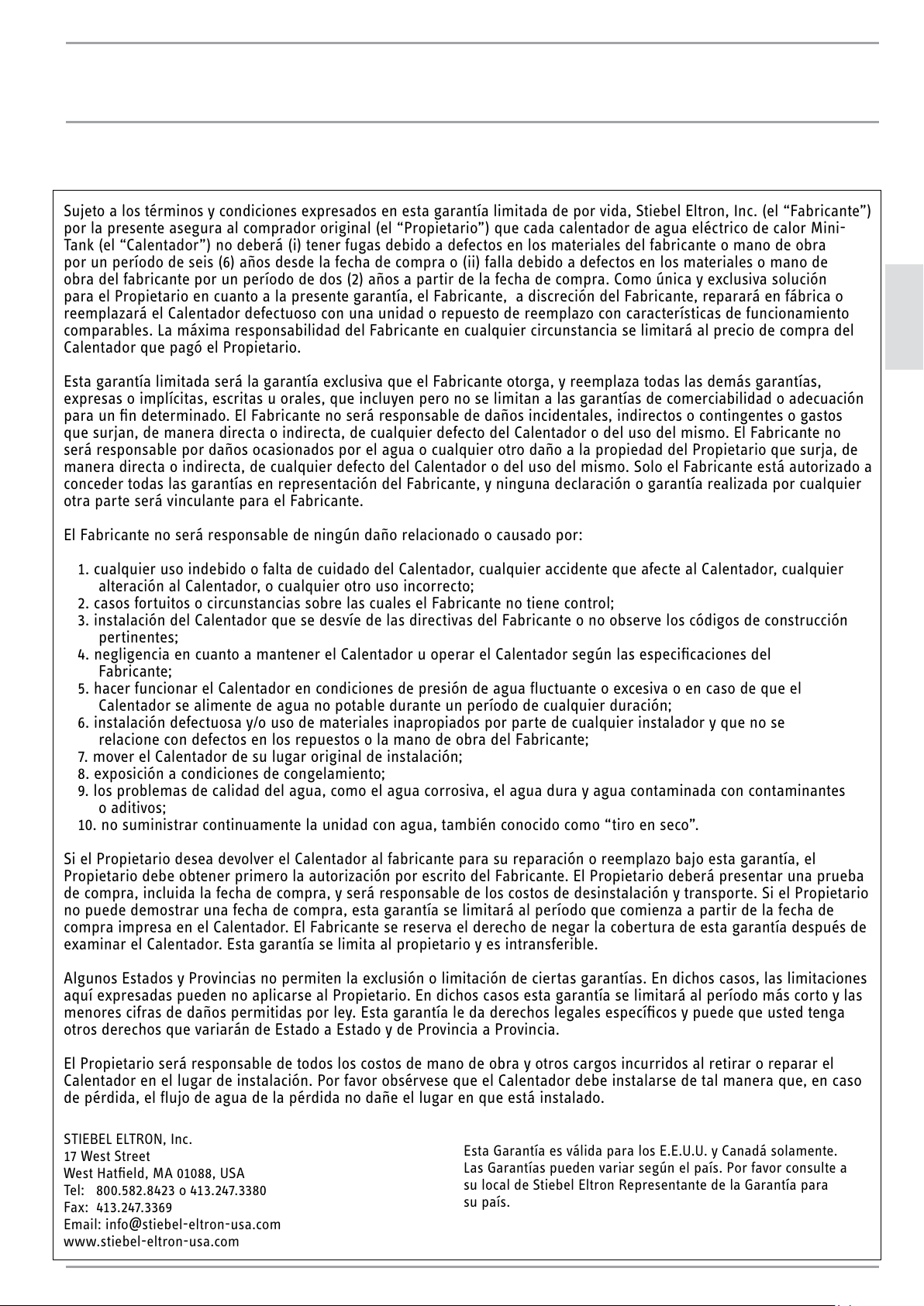
13. Garantía Limitada
Sujeto a los términos y condiciones expresados en esta garantía limitada de por vida, Stiebel Eltron, Inc. (el “Fabricante”)
por la presente asegura al comprador original (el “Propietario”) que cada calentador de agua eléctrico de calor Mini-
Tank (el “Calentador”) no deberá (i) tener fugas debido a defectos en los materiales del fabricante o mano de obra
por un período de seis (6) años desde la fecha de compra o (ii) falla debido a defectos en los materiales o mano de
obra del fabricante por un período de dos (2) años a partir de la fecha de compra. Como única y exclusiva solución
para el Propietario en cuanto a la presente garantía, el Fabricante, a discreción del Fabricante, reparará en fábrica o
reemplazará el Calentador defectuoso con una unidad o repuesto de reemplazo con características de funcionamiento
comparables. La máxima responsabilidad del Fabricante en cualquier circunstancia se limitará al precio de compra del
Calentador que pagó el Propietario.
Esta garantía limitada será la garantía exclusiva que el Fabricante otorga, y reemplaza todas las demás garantías,
expresas o implícitas, escritas u orales, que incluyen pero no se limitan a las garantías de comerciabilidad o adecuación
para un fin determinado. El Fabricante no será responsable de daños incidentales, indirectos o contingentes o gastos
que surjan, de manera directa o indirecta, de cualquier defecto del Calentador o del uso del mismo. El Fabricante no
será responsable por daños ocasionados por el agua o cualquier otro daño a la propiedad del Propietario que surja, de
manera directa o indirecta, de cualquier defecto del Calentador o del uso del mismo. Solo el Fabricante está autorizado a
conceder todas las garantías en representación del Fabricante, y ninguna declaración o garantía realizada por cualquier
otra parte será vinculante para el Fabricante.
El Fabricante no será responsable de ningún daño relacionado o causado por:
1. cualquier uso indebido o falta de cuidado del Calentador, cualquier accidente que afecte al Calentador, cualquier
alteración al Calentador, o cualquier otro uso incorrecto;
2. casos fortuitos o circunstancias sobre las cuales el Fabricante no tiene control;
3. instalación del Calentador que se desvíe de las directivas del Fabricante o no observe los códigos de construcción
pertinentes;
4. negligencia en cuanto a mantener el Calentador u operar el Calentador según las especificaciones del
Fabricante;
5. hacer funcionar el Calentador en condiciones de presión de agua fluctuante o excesiva o en caso de que el
Calentador se alimente de agua no potable durante un período de cualquier duración;
6. instalación defectuosa y/o uso de materiales inapropiados por parte de cualquier instalador y que no se
relacione con defectos en los repuestos o la mano de obra del Fabricante;
7. mover el Calentador de su lugar original de instalación;
8. exposición a condiciones de congelamiento;
9. los problemas de calidad del agua, como el agua corrosiva, el agua dura y agua contaminada con contaminantes
o aditivos;
10. no suministrar continuamente la unidad con agua, también conocido como “tiro en seco”.
Si el Propietario desea devolver el Calentador al fabricante para su reparación o reemplazo bajo esta garantía, el
Propietario debe obtener primero la autorización por escrito del Fabricante. El Propietario deberá presentar una prueba
de compra, incluida la fecha de compra, y será responsable de los costos de desinstalación y transporte. Si el Propietario
no puede demostrar una fecha de compra, esta garantía se limitará al período que comienza a partir de la fecha de
compra impresa en el Calentador. El Fabricante se reserva el derecho de negar la cobertura de esta garantía después de
examinar el Calentador. Esta garantía se limita al propietario y es intransferible.
Algunos Estados y Provincias no permiten la exclusión o limitación de ciertas garantías. En dichos casos, las limitaciones
aquí expresadas pueden no aplicarse al Propietario. En dichos casos esta garantía se limitará al período más corto y las
menores cifras de daños permitidas por ley. Esta garantía le da derechos legales específicos y puede que usted tenga
otros derechos que variarán de Estado a Estado y de Provincia a Provincia.
El Propietario será responsable de todos los costos de mano de obra y otros cargos incurridos al retirar o reparar el
Calentador en el lugar de instalación. Por favor obsérvese que el Calentador debe instalarse de tal manera que, en caso
de pérdida, el flujo de agua de la pérdida no dañe el lugar en que está instalado.
STIEBEL ELTRON, Inc.
17 West Street
West Hatfield, MA 01088, USA
Tel: 800.582.8423 o 413.247.3380
Fax: 413.247.3369
Email: info
@
stiebel-eltron-usa.com
www.stiebel-eltron-usa.com
Esta Garantía es válida para los E.E.U.U. y Canadá solamente.
Las Garantías pueden variar según el país. Por favor consulte a
su local de Stiebel Eltron Representante de la Garantía para
su país.

24 | SHC 2.5 / SHC 4 www.stiebel-eltron-usa.com
TABLE DES MATIÈRES | MODE D’EMPLOI | INSTALLATION
1. Généralités _____________________________________________25
2. Mesures de précaution relatives à la sécurité ____ 26
3. Description ____________________________________________ 27
4. Inscrivez votre produit ______________________________ 27
5. Description technique _______________________________ 27
6. Données techniques _________________________________ 27
6.1 Dimensions, SHC 2.5 �������������������������������������27
6.2 Dimensions, SHC 4 ����������������������������������������28
7. Recommandations générales _______________________ 28
8. Fixation de l’appareil ________________________________ 28
9. Branchements de plomberie ________________________ 29
9.1 Remplissage du chauffe-eau �������������������������� 30
10. Configuration électrique_____________________________ 30
10.1 Diagramme électrique ���������������������������������� 30
11. Réglages ______________________________________________ 30
12. Instructions relatives à l’entretien __________________31
12.1 Détartrer l’élément chauffant ��������������������������31
12.2 Utilisée manuellement de la soupape de
décharge de pression et de température ������������31
12.3 Vidange du chauffe-eau ���������������������������������31
12.4 Retrait du couvercle ��������������������������������������32
12.5 Retrait de l’élément chauffant��������������������������32
12.6 Détartrage de l’élément chauffant ��������������������32
12.7 Remplacement de l’élément chauffant ���������������32
12.8 Remplacement de l’anode ������������������������������32
12.9 Vanne d’isolement de sécurité �������������������������33
13. Garantie Limitée ______________________________________ 34
DIRECTIVES IMPORTANTES
RELATIVES À LA SÉCURITÉ
!
AVERTISSEMENT :
POUR RÉDUIRE LE RISQUE D’INCENDIE, DE CHOC
ÉLECTRIQUE OU DE BLESSURES, LORSQUE VOUS
UTILISEZ DES APPAREILS ÉLECTRIQUES RESPECTEZ
LES DIRECTIVES RELATIVES À LA SÉCURITÉ :
1. LIRE TOUTES LES INSTRUCTIONS AVANT D’UTILISER
CE CHAUFFE-EAU.
2. Ce chauffe-eau doit être mis à la terre. Ne connectez
qu’à une prise correctement mise à la terre! Voir les
instructions spéciales de mise à la terre dans le cha-
pitre 10, « Configuration électrique », p. 29.
3. Installez ou placez ce chauffe-eau strictement
en conformité avec les instructions d’installation
ci-jointes.
4. N’utilisez ce chauffe-eau qu’aux fins décrites dans ce
manuel.
5. N’utilisez pas de rallonge pour ce chauffe-eau.
Si aucune prise n’est disponible à proximité du
chauffe-eau, demandez à un électricien agréé d’en
installer une correctement.
6. Il faut, comme pour tout appareil ménager, surveil-
ler étroitement les enfants lorsqu’ils l’utilisent.
7. N’utilisez pas ce chauffe-eau si le câble ou la prise
sont endommagés, s’il ne fonctionne pas correcte-
ment ou s’il a été endommagé ou laissé tomber.
8. Ne confiez l’entretien de cet appareil qu’à des pres-
tataires d’entretien agréés. Adressez-vous à l’agence
d’entretien agréée la plus proche pour les opéra-
tions d’inspection, de réparation ou de réglage.
CONSERVER CES INSTRUCTIONS
MODE D’EMPLOI
Généralités
FRANÇAIS
www.stiebel-eltron-usa.com SHC 2.5 / SHC 4 | 25
1. Généralités
!
ATTENTION :
POUR RÉDUIRE LE RISQUE DE PRESSIONS ET DE
TEMPÉRATURES EXCESSIVES DANS CE CHAUFFE-
EAU, INSTALLEZ LES DISPOSITIFS DE PROTECTION
POUR LES TEMPÉRATURES ET LA PRESSION STI-
PULÉS DANS LES CODES LOCAUX, AVEC AU MOINS
UNE SOUPAPE DE DÉCHARGE DE TEMPÉRATURE ET
DE PRESSION COMBINÉE CERTIFIÉE PAR UN LABO-
RATOIRE D’ESSAIS AGRÉÉ AU NIVEAU NATIONAL
QUI INSPECTE RÉGULIÈREMENT LES ÉQUIPEMENTS
OU MATÉRIAUX RÉPERTORIÉS, ET SATISFAISANT
AUX EXIGENCES RELATIVES AUX SOUPAPES DE
DÉCHARGE ET AUX DISPOSITIFS DE COUPURE AU-
TOMATIQUE DU GAZ POUR LES SYSTÈMES D’ALI-
MENTATION EN EAU CHAUDE DE LA NORME ANSI
Z21.22. CETTE SOUPAPE DOIT ÊTRE MARQUÉE
AVEC UNE PRESSION PRÉRÉGLÉE MAXIMALE NE
DEVANT PAS DÉPASSER LA PRESSION D’EXPLOI-
TATION MAXIMALE DU CHAUFFE-EAU. INSTALLEZ
LA SOUPAPE SUR L’OUVERTURE INDIQUÉE À CET
EFFET DANS LE CHAUFFE-EAU ET DIRIGEZ-LA OU
POSEZ UNE CANALISATION DE SORTE QUE TOUT
ÉCOULEMENT SE FERA ÉGALEMENT DANS LES 152
MM AU-DESSUS, ET À N’IMPORTE QUELLE DIS-
TANCE AU-DESSOUS, DU PLANCHER STRUCTURAL
ET QU’ELLE NE POURRA PAS ENTRER EN CONTACT
AVEC DES PIÈCES ÉLECTRIQUES SOUS TENSION.
L’OUVERTURE DE L’ÉCOULEMENT NE PEUT ÊTRE
BLOQUÉE NI RÉTRÉCIE POUR QUELLE RAISON QUE
CE SOIT.
Veuillez lire ce manuel dans son intégralité. Le non-respect
des directives contenues dans les guides, les directives et les
règlements pourrait entraîner des dégâts matériels ou des
blessures. Des installations, réglages, modifications, entre-
tiens et utilisations non conformes de cet appareil pourraient
provoquer des blessures graves.
Cet appareil doit être installé par un électricien et un plom-
bier agréés. L’installation doit se faire conformément aux
codes de l’électricité et de la plomberie en vigueur au niveau
national, provincial et local. Il incombe à l’installateur d’ins-
taller correctement cet appareil. Le non-respect des direc-
tives d’installation et du mode d’emploi, ou une utilisation
incorrecte aura pour effet d’annuler la garantie.
Conserver ces instructions pour consultation ultérieure.
L’installateur doit laisser ces instructions au consommateur.
Pour toute question relative à l’installation, l’utilisation ou le
fonctionnement de ce chauffe-eau, ou si vous avez besoin de
manuels d’installation supplémentaires, veuillez vous adres-
ser à notre service technique en composant le (800) 582-8423
(Canada et États-Unis uniquement). Si vous appelez depuis
un pays autre que le Canada ou les États-Unis, veuillez com-
poser le 413-247-3380 aux États-Unis et nous vous mettrons
en contact avec un centre d’entretien Stiebel Eltron agréé
situé dans votre région.
1. Ne mettez pas le chauffe-eau là où les canalisations
d’eau pourraient être soumises à des températures
au-dessous de zéro.
2. Il est conseillé d’avoir un drain au plancher à proxi-
mité pour vidanger facilement l’appareil en cas de
nécessité.
3. Installez le chauffe-eau de sorte qu’en cas de fuite,
l’eau qui s’échapperait de l’appareil ne pourrait pas
endommager ce qui se trouve autour du chauffe-eau.
Le fabricant ne saurait, en aucun cas, être tenu res-
ponsable pour tout dégât causé par l’eau provoqué
par ce chauffe-eau.
4. Lorsque vous installez le chauffe-eau, veillez à ce
qu’il y ait suffisamment de dégagement autour de
l’appareil pour faciliter l’entretien et les réparations.
!
SYMBOLE D’ALERTE À LA SÉCURITÉ.
IL SERT À VOUS AVERTIR QU’IL EXISTE UN DANGER
DE BLESSURE POTENTIEL. RESPECTEZ TOUS LES
MESSAGES RELATIFS À LA SÉCURITÉ MENTIONNÉS
APRÈS CE SYMBOLE POUR ÉVITER LA POSSIBILITÉ
DE BLESSURE, VOIRE DE DÉCÈS.
MODE D’EMPLOI
Mesures de précaution relatives à la sécurité
26 | SHC 2.5 / SHC 4 www.stiebel-eltron-usa.com
2. Mesures de précaution relatives à
la sécurité
!
VEUILLEZ LIRE ET RESPECTER CES INSTRUC-
TIONS.
LE NON-RESPECT DE CES INSTRUCTIONS POURRAIT
ENTRAÎNER DES BLESSURES GRAVES, VOIRE MOR-
TELLES.
CET APPAREIL DOIT ÊTRE INSTALLÉ PAR UN
PLOMBIER AGRÉÉ. L’INSTALLATION DOIT SE FAIRE
CONFORMÉMENT AUX CODES DE L’ÉLECTRICITÉ ET
DE LA PLOMBERIE EN VIGUEUR AU NIVEAU NATIO-
NAL, PROVINCIAL ET LOCAL.
CONFIEZ L’ENTRETIEN DE CET APPAREIL À UN
CENTRE D’ENTRETIEN AGRÉÉ.
AVANT DE PROCÉDER À TOUTE OPÉRATION D’INS-
TALLATION, DE RÉGLAGE, DE MODIFICATION OU
D’ENTRETIEN DE CET APPAREIL, DÉBRANCHEZ
LE CÂBLE D’ALIMENTATION. LE NON-RESPECT
DE CETTE DIRECTIVE POURRAIT ENTRAÎNER DES
BLESSURES GRAVES, VOIRE MORTELLES.
NE RETIREZ JAMAIS LE COUVERCLE DE L’APPAREIL
À MOINS D’AVOIR COUPÉ L’ALIMENTATION ÉLEC-
TRIQUE DE L’APPAREIL. LE NON-RESPECT DE CETTE
DIRECTIVE POURRAIT ENTRAÎNER DES BLESSURES
GRAVES, VOIRE MORTELLES.
NE RANGEZ, NI N’UTILISEZ PAS DE L’ESSENCE OU
D’AUTRES VAPEURS OU LIQUIDES INFLAMMABLES
À PROXIMITÉ DE CET APPAREIL OU DE TOUT AUTRE
APPAREIL.
!
DANGER :
LES TEMPÉRATURES DE L’EAU SUPÉRIEURES À 52
°C (125 °F) PEUVENT PROVOQUER DES BRÛLURES
GRAVES INSTANTANÉES, VOIRE MORTELLES EN CAS
D’ÉBOUILLANTAGE. LE RISQUE D’ÉBOUILLANTAGE
PAR L’EAU TRÈS CHAUDE EXISTE SI LE THERMOSTAT
DE L’APPAREIL EST RÉGLÉ À UNE TEMPÉRATURE
TROP ÉLEVÉE. DANS LE CAS DE RÉSIDENCES AVEC
DE JEUNES ENFANTS, DES PERSONNES HANDICA-
PÉES OU ÂGÉES, IL EST FORTEMENT CONSEILLÉ DE
RÉGLER LE THERMOSTAT À 49 °C (120 °F) OU MOINS
POUR ÉVITER LA POSSIBILITÉ DE BLESSURES PRO-
VOQUÉES PAR L’EAU TRÈS CHAUDE.
!
AVERTISSEMENT :
CE CHAUFFE-EAU DOIT ÊTRE INSTALLÉ STRICTE-
MENT CONFORMÉMENT AUX INSTRUCTIONS CI-
JOINTES ET AUX CODES ÉLECTRIQUES ET DE LA
CONSTRUCTION LOCAUX. IL EST POSSIBLE QUE LES
CONNEXIONS VERS LE CHAUFFE-EAU LUI-MÊME
PRÉSENTENT DES FUITES. IL EST PAR CONSÉQUENT
IMPÉRATIF QUE LE CHAUFFE-EAU SOIT INSTALLÉ
DE SORTE QUE TOUTE FUITE D’EAU SERA DIRIGÉE
VERS UN DRAIN ADÉQUAT POUR ÉVITER TOUT
DOMMAGE AU BÂTIMENT, À L’AMEUBLEMENT, À
LA MOQUETTE OU À TOUT AUTRE BIEN. NI LE FA-
BRICANT, NI LE DISTRIBUTEUR NE PEUVENT ÊTRE
TENUS RESPONSABLES POUR LES DÉGÂTS PRO-
VOQUÉS PAR LES FUITES D’EAU PROVENANT DU
CHAUFFE-EAU, LA SOUPAPE DE PRESSION OU LES
RACCORDS CONNEXES SI UNE OPTION D’ÉCOULE-
MENT POUR L’EAU EN CAS DE FUITE N’A PAS ÉTÉ
PRÉVUE.
!
ATTENTION :
SI CE CHAUFFE-EAU ALIMENTANT UN SYSTÈME
D’EAU CHAUDE N’A PAS SERVI PENDANT UNE PÉ-
RIODE DE TEMPS ASSEZ LONGUE (EN PRINCIPE
DEUX SEMAINES OU PLUS), IL EST POSSIBLE QU’ON
NOTE UNE PRODUCTION DE GAZ HYDROGÈNE. CE-
LUI-CI EST EXTRÊMEMENT INFLAMMABLE.
POUR RÉDUIRE LE RISQUE DE BLESSURES DANS CE
CAS-LÀ, IL EST CONSEILLÉ D’OUVRIR LE ROBINET
D’EAU CHAUDE DE L’ÉVIER DE CUISINE PENDANT
PLUSIEURS MINUTES AVANT D’UTILISER UN AP-
PAREIL MÉNAGER ÉLECTRIQUE BRANCHÉ AU SYS-
TÈME D’EAU CHAUDE.
EN PRÉSENCE D’HYDROGÈNE, ON REMARQUERA
UN BRUIT INHABITUEL RESSEMBLANT À DE L’AIR
S’ÉCHAPPANT DE LA CANALISATION AU MOMENT
OÙ L’EAU COMMENCE À COULER. IL NE FAUT NI
FUMER, NI AVOIR UNE FLAMME NUE PRÈS DU RO-
BINET AU MOMENT OÙ ON L’OUVRE.
PURGE MANUELLE MENSUEL DE LA SOUPAPE P &
T PERMETTRA DE RÉDUIRE CET EFFET. VOIR 12.2,
« UTILISÉE MANUELLEMENT DE LA SOUPAPE DE
DÉCHARGE DE PRESSION ET DE TEMPÉRATURE»,
P. 31
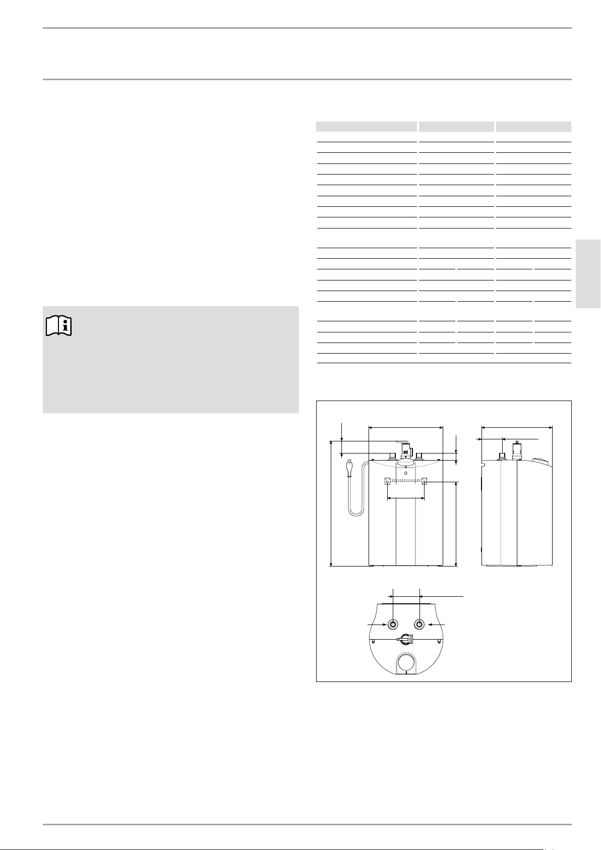
MODE D’EMPLOI
Description
FRANÇAIS
www.stiebel-eltron-usa.com SHC 2.5 / SHC 4 | 27
3. Description
Ces chauffe-eau SHC peuvent être utilisés dans la plupart des
utilisations de lavabos. Ils sont conçus pour fournir de l’eau
chaude pour se laver les mains et pour les éviers de cuisine
dans les résidences, les commerces ou en milieu industriel.
Ces chauffe-eau peuvent remplacer les systèmes de chauffe-
eau traditionnels composés d’un chauffe-eau central avec
des canalisations d’eau chaude allant vers plusieurs robinets.
Les chauffe-eau SHC sont légers et compacts et fabriqués de
sorte à être installés facilement. Ces appareils sont conçus
pour être fixés au mur. Ces appareils sont conçus pour fonc-
tionner avec une pression d’eau normale.
4. Inscrivez votre produit
NOTE:
Vous devez inscrire votre produit dans les 90 jours
qui suivent la date d’achat sur notre site internet
pour activer la garantie normale ou pour pouvoir
réclamer la garantie prolongée. Rendez-vous à
notre site internet à l’adresse suivante : www.
stiebel-eltron-usa.com et cliquez sur « Register
Your Product » (inscrivez votre produit).
Avant de lancer le processus d’inscription, nous vous
conseillons d’avoir à portée de main la documentation
nécessaire, à savoir :
Modèle, Exemple : SHC 2.5 (de l’étiquette située sur le
dessus de l’appareil, au centre)
Numéro apparaissant après « Nr. » (N°)
Lieu d’achat
Date d’achat
Prénom et nom de famille
Adresse courriel
Adresse postale
Numéro de téléphone
En cas de questions à propos du processus d’inscription
ou des options pour la garantie, veuillez contacter Stiebel
Eltron USA directement en composant le (800) 582-8423.
5. Description technique
Le récipient à pression du chauffe-eau est en acier soudé
vitrifié et doté d’une anode soluble. L’isolation thermique
est en polystyrène.
Le chauffe-eau est doté d’un thermostat et d’un interrupteur
de sécurité de limite supérieure de température. Une sou-
pape de décharge de pression et de température est fournie
avec l’appareil.
6. Données techniques
SHC 2.5 SHC 4
Article n° 233219 234046
Tension 110–120 V 110–120 V
Puissance en Watts, max 1300 W 1300 W
Ampérage, max 11.3 A 11.3 A
Phase Monophasé, 1/N/PE Monophasé, 1/N/PE
Fréquence 50/60 Hz 50/60 Hz
Type d’installation Sous l’évier Sous l’évier
Matériau du réservoir interne Acier Acier
Matériau de l’enveloppe Plastique Plastique
Matériau de l’isolation
thermique
Polystyrène
Polystyrène
Couleur blanc blanc
Volume d’eau nominal 10 l 2.65 gal 15 l 4.0 gal
Perte de énergie latente
1
0.37 kWh / jour 0.39 kWh / jour
Temps de récupération 18 minutes 27 minutes
Plage des températures 30–60 °C 86–140 °F 30–60 °C 86–140 °F
Pression maximale de
fonctionnement
1.0 MPa
150 psi
1.0 MPa
150 psi
Poids (à vide) 7.2 kg 15.9 lbs 9.0 kg 19.8 lbs
Poids (à plein) 17.5 kg 38.6 lbs 24.0 kg 52.9 lbs
Raccordements de l’eau ½ po filetage NPT ½ po filetage NPT
1
Mesurée à 131 ° F / 55 ° C la température de consigne de 68 ° F / 20 ° C température ambiante de l’air.
6.1 Dimensions, SHC 2.5
18 11/16″ (475)
1 1/16″ (26.5)12 5/8″ (320)
1 3/4" (45)
3 15/16" (100)
11″ (280)
3 1/8″ (80)
10 5/8″ (270)
5 1/2" (140)
po. (mm)
Sortie d’eau
chaude
1/2 po. NPT
let mâle
Arrivée d’eau
froide
1/2 po. NPT
let mâle

28 | SHC 2.5 / SHC 4 www.stiebel-eltron-usa.com
INSTALLATION
Recommandations générales
6.2 Dimensions, SHC 4
19 3/4″ (501)
15/16″ (23)13 7/16″ (342)
1 15/16" (49)
3 15/16" (100)
12 5/8″ (320)
3 1/8″ (80)
12 1/2″ (318)
7 7/8" (200)
7. Recommandations générales
Cet appareil doit être installé par des professionnels agréés.
Il est impératif de respecter tous les codes locaux et provin-
ciaux en vigueur.
Le fabricant rejette toute responsabilité pour tout dommage
causé par le non-respect de ces instructions d’installation ou
par une mauvaise installation exécutée par un installateur
non agréé.
NOTE:
La soupape de décharge de pression et de tem-
pérature doit être utilisée manuellement une fois
par mois. Voir 12.2, « Utilisée manuellement de la
soupape de décharge de pression et de tempéra-
ture», p. 31
NOTE:
Choisissez un emplacement qui permette d’accé-
der facilement à l’appareil pour l’entretien et les
réparations.
Le chauffe-eau doit être installé à au moins
203 mm du plafond ou des murs adjacents.
8. Fixation de l’appareil
!
AVIS :
L’APPAREIL DOIT ÊTRE INSTALLÉ VERTICALEMENT
AVEC LES RACCORDEMENTS D’EAU DIRIGÉS VERS
LE HAUT.
AVERTISSEMENT :
N’INSTALLEZ PAS L’APPAREIL À UN ENDROIT OÙ
IL POURRAIT ÊTRE ÉCLABOUSSÉ RÉGULIÈREMENT
PAR DE L’EAU. CELA POURRAIT ENTRAÎNER UN
CHOC ÉLECTRIQUE.
ATTENTION :
LES CANALISATIONS D’ÉCOULEMENT D’EAU
CHAUDE QUITTANT L’APPAREIL PEUVENT ÊTRE
CHAUDES AU TOUCHER. IL FAUT ISOLER LES CA-
NALISATIONS D’ÉCOULEMENT D’EAU CHAUDES
SITUÉES À MOINS DE 91 CM (36 PO) À CAUSE DU
RISQUE DE BRÛLURES ENCOURU PAR LES ENFANTS.
!
AVIS :
CET APPAREIL NE DOIT PAS ÊTRE INSTALLÉ
À UN ENDROIT SUSCEPTIBLE D’ÊTRE EXPOSÉ
AU GEL (TEMPÉRATURES INFÉRIEURES À 2 °C
[36 °F]). SI L’APPAREIL RISQUE D’ÊTRE EXPOSÉ AU
GEL, IL FAUT PURGER TOUTE L’EAU DE L’APPAREIL.
LE NON-RESPECT DE CETTE DIRECTIVE ANNULE
TOUTES LES GARANTIES.
L’APPAREIL DOIT ÊTRE SITUÉ DANS UN ENDROIT OÙ
LES FUITES D’EAU PROVENANT DE L’APPAREIL OU
DES CONNEXIONS NE RISQUENT PAS D’ENTRAÎNER
DES DOMMAGES À SON ENVIRONNEMENT IMMÉ-
DIAT. SI L’INSTALLATION NE PEUT AVOIR LIEU AIL-
LEURS, IL EST CONSEILLÉ D’INSTALLER UN BAC DE
RÉCUPÉRATION SOUS L’APPAREIL.
1. Percez deux (2) trous de 6 mm (1/4 po) dans le trou là
où le chauffe-eau sera fixé.
2. Enfoncez les ancrages muraux en plastique.
3. Fixez le support mural au mur.
4. Accrochez le chauffe-eau au support mural.
5. Tirez le chauffe-eau vers le bas afin de bien l’asseoir
sur le support.
po. (mm)
Sortie d’eau
chaude
1/2″ NPT
let mâle
Arrivée d’eau
froide
1/2″ NPT
let mâle
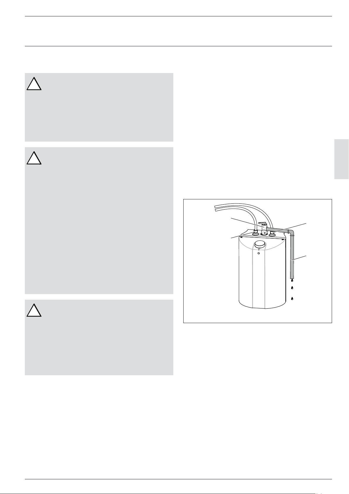
FRANÇAIS
www.stiebel-eltron-usa.com SHC 2.5 / SHC 4 | 29
INSTALLATION
Branchements de plomberie
9. Branchements de plomberie
!
IMPORTANT :
SI LES CANALISATIONS D’EAU SONT EN CUIVRE
OU EN BRONZE, UTILISEZ LES RACCORDEMENTS
DIÉLECTRIQUES POUR ÉVITER LA CORROSION DU
CHAUFFE-EAU. SI AUCUNE ISOLATION DIÉLEC-
TRIQUE N’EST FOURNIE, CELA POURRAIT ENTRAÎ-
NER UNE DÉFAILLANCE PRÉMATURÉE DU RÉSER-
VOIR OU DU MAMELON ET ANNULER VOTRE GA-
RANTIE.
!
AVIS :
L’EAU DURE OU L’EAU AVEC UNE TENEUR ÉLEVÉE
EN MINÉRAUX PEUT ENDOMMAGER L’APPAREIL.
LES DÉGÂTS CAUSÉS PAR LE TARTRE OU UNE TE-
NEUR ÉLEVÉE EN MINÉRAUX NE SONT PAS COU-
VERTS PAS LA GARANTIE.
ATTENTION :
POUR RÉDUIRE LE RISQUE DE PRESSION OU DE
TEMPÉRATURES EXCESSIVES DANS LE CHAUFFE-
EAU, UNE SOUPAPE DE DÉCHARGE DE PRESSION ET
DE TEMPÉRATURE (P & T) A ÉTÉ INSTALLÉE.
ATTENTION :
TOUJOURS REMPLIR LE RÉSERVOIR DE L’APPAREIL
AVEC DE L’EAU AVANT DE BRANCHER LE CORDON
D’ALIMENTATION DU CHAUFFE-EAU DANS UNE
PRISE ÉLECTRIQUE. NE PAS LE FAIRE SE TRADUIRA
PAR DES DOMMAGES PERMANENTS À L’APPAREIL
DE CHAUFFAGE DE L’EAU.
!
AVIS :
LORSQU’UN CHAUFFE-EAU EST INSTALLÉ DANS UN
SYSTÈME D’ALIMENTATION D’EAU FERMÉ, COMME
DANS LE CAS OÙ UN CLAPET ANTI-RETOUR SUR
LA CANALISATION D’EAU FROIDE EST INTÉGRÉ, IL
FAUT PRÉVOIR UN DISPOSITIF POUR CONTRÔLER
LA DILATATION THERMIQUE. CONTACTEZ LA SO-
CIÉTÉ DES EAUX OU L’INSPECTEUR EN PLOMBERIE
MUNICIPAL POUR PLUS DE DÉTAILS SUR LA MA-
NIÈRE DE CONTRÔLER CETTE SITUATION.
Branchez la canalisation d’eau froide au raccordement d’eau
froide de l’appareil (bleu). Branchez la canalisation d’eau
chaude au raccordement d’eau chaude de l’appareil (rouge).
Veillez à ce que le chauffe-eau soit installé de niveau.
Installez la vanne d’isolement sur l’alimentation d’eau froide
du chauffe-eau. Il s’agit d’une vanne d’isolement d’urgence.
Elle doit rester ouverte lorsque le chauffe-eau fonctionne.
Lorsque vous utilisez des canalisations en cuivre, soudez un
morceau de canalisation sur un raccord fileté (union) avant
de visser l’adaptateur au réservoir.
LES CONNECTEURS POUR TUYAUX FLEXIBLES TRESSÉS SONT
ÉGALEMENT CONSEILLÉS.
N’APPLIQUEZ PAS DE CHALEUR DIRECTEMENT AU NIVEAU
DES CONNEXIONS D’ARRIVÉE OU DE SORTIE.
NIVEAU
DES CONNEXIONS D’ARRIVÉE OU DE SORTIE.
Une soupape P & T certifiée est montée sur le chauffeeau
par le fabricant avec la sortie orientée vers la droite. Si cette
position doit être changée, des fuites pourraient survenir,
en particulier si elle est vissée dans le sens antihoraire, et
la soupape P & T doit être étanchéifiée à nouveau. Après
tous les travaux de plomberie a été achevée, la soupape de
sûreté P & T doit être vérifié pour une bonne étanchéité afin
de s’assurer qu’aucune fuite.
Pendant le chauffage le volume d’eau et la pression de l’eau
augmentent dans le réservoir. Il est possible que la soupape
de sécurité présente des fuites. C’est tout à fait normal.
4
3
1
2
1. Soupape de décharge de pression et de température
2. Sortie d’eau chaude
3. Arrivée d’eau froide
4. Conduite d’évacuation
Installez une conduite d’évacuation depuis la soupape de
décharge jusqu’à un évier ou un drain. Dirigez la canalisation
de sorte que l’écoulement se fera également dans les 152
mm au-dessus et à n’importe quelle distance au-dessous du
plancher structural et qu’elle ne pourra pas entrer en contact
avec des pièces électriques sous tension.
NE BOUCHEZ PAS, NI NE FILETEZ PAS L’EXTRÉMITÉ DE LA
CONDUITE D’ÉVACUATION; ELLE DOIT RESTER OUVERTE ET
CONSERVER SON DIAMÈTRE INITIAL.
La soupape P & T est certifiée par un laboratoire d’essais de
réputation nationale qui inspecte régulièrement les équipe-
ments répertoriés. Elle satisfait aux exigences relatives aux
soupapes de décharge et aux dispositifs d’isolement auto-
matique pour les systèmes d’alimentation en eau chaude de
la norme ANSI 121.22.0979.

30 | SHC 2.5 / SHC 4 www.stiebel-eltron-usa.com
INSTALLATION
Conguration électrique
La pression maximale est inscrite sur la soupape P & T et elle
ne doit pas dépasser la pression de fonctionnement maxi-
male du chauffe-eau (150 lb/po²).
LA CONDUITE D’ÉVACUATION
- Ne doit pas être de plus petite taille que la conduite de
sortie de la soupape, ni posséder des raccordements
réducteurs.
- Ne doit être ni bouchée, ni bloquée.
- Doit être en matériau compatible avec l’eau chaude.
- Ne doit pas dépasser 4,6 m (15 pi) de long.
- Ne doit pas présenter plus de deux coudes.
- Doit arriver dans un drain adéquat.
- Ne doit pas avoir une soupape entre la soupape de dé-
charge et le réservoir.
9.1 Remplissage du chauffe-eau
Pour remplir le chauffe-eau :
1. Ouvrez le robinet d’eau chaude.
2. Ouvrez le robinet d’alimentation en eau froide.
3. Lorsque l’eau commence à s’écouler du robinet d’eau
chaude, cela implique que le réservoir est rempli.
4. Fermez le robinet d’eau chaude.
5. Vérifiez que le système n’a aucune fuite.
10. Configuration électrique
!
ATTENTION :
NE JAMAIS BRANCHER LE CÂBLE DU CHAUFFE-EAU
DANS UNE PRISE ÉLECTRIQUE AVANT QU’IL SOIT
PLEIN D’EAU. SINON, L’APPAREIL POURRAIT ÊTRE
ENDOMMAGÉ SANS OPTION DE RÉPARATION
AVIS :
LE CHAUFFE-EAU DOIT ÊTRE CONNECTÉ À UNE
PRISE AVEC MISE À LA TERRE.
CE CHAUFFE-EAU A ÉTÉ CONÇU POUR FONC-
TIONNER SOUS DU 110 – 120 V. N’UTILISEZ PAS
CE CHAUFFE-EAU SOUS UNE AUTRE TENSION. LE
NON-RESPECT DE CETTE DIRECTIVE PEUT ENTRAÎ-
NER DES BLESSURES ET DES DÉGÂTS MATÉRIAUX.
LE CHAUFFE-EAU EST FOURNI AVEC UN CÂBLE
ÉLECTRIQUE AVEC FICHE. SI LE CÂBLE EST EN-
DOMMAGÉ OU TROP COURT, IL FAUT QU’IL SOIT
REMPLACÉ PAR UN ÉLECTRICIEN AGRÉÉ.
Veillez à ce que tout l’air soit purgé du système, ouvrez le
robinet d’eau chaude de vos lavabos jusqu’à ce que l’eau
s’écoule régulièrement de tous les robinets. Si ce n’était pas
le cas, votre élément pourrait être endommagé.
Le chauffe-eau doit être connecté à UNE PRISE AVEC MISE
À LA TERRE.
L’appareil est doté d’un câble pour brancher le chauffe-eau
à une prise électrique. Il est impératif de respecter tous les
codes locaux et provinciaux en vigueur. Installez le disjonc-
teur correct dans le panneau du disjoncteur.
Le chauffe-eau a été fabriqué et câblé conformément aux
exigences des normes UL.
Une limite supérieure de température avec ré-enclenche-
ment manuel a été installée en usine pour interrompre l’ali-
mentation électrique en cas de défaillance du thermostat.
N’UTILISEZ PAS ce chauffe-eau sous une autre tension. Le
non-respect de cette directive peut entraîner des blessures
et des dégâts matériaux.
10.1 Diagramme électrique
L
A B
N PE
1 2
D0000035810
4
5
3
2
1
1. Élément chauffant
2. Témoin lumineux
3. Coupure
4. Thermostat
5. Réservoir
11. Réglages
Le chauffe-eau est doté d’un thermostat réglable qui permet
de contrôler automatiquement la température de l’eau. Le té-
moin reste allumé lorsque l’eau est en train d’être chauffée.
La température est réglée en tournant le bouton dans le sens
antihoraire (vers la gauche) pour augmenter la température
et dans le sens horaire (vers la droite) pour la réduire.
Le thermostat du chauffe-eau peut être programmé pour
empêcher que l’eau ne gèle. Cette position maintient la tem-
pérature interne au-dessus de zéro.
La tuyauterie à l’extérieur du chauffe-eau et le robinet ne
sont pas protégés contre le gel.
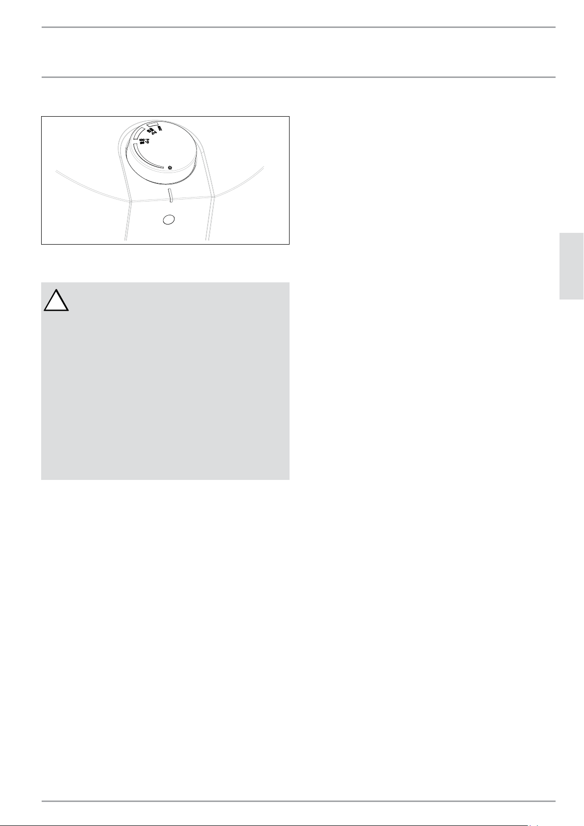
FRANÇAIS
www.stiebel-eltron-usa.com SHC 2.5 / SHC 4 | 31
INSTALLATION
Instructions relatives à l’entretien
Réglage pour la protection contre le gel
D0000034989
12. Instructions relatives à l’entretien
!
AVERTISSEMENT :
AVANT TOUTE OPÉRATION DE RÉPARATION OU DE
NETTOYAGE DU CHAUFFE-EAU, DÉBRANCHEZ LE
CHAUFFE-EAU DE LA PRISE ÉLECTRIQUE.
LA SOUPAPE DE DÉCHARGE DE PRESSION ET DE
TEMPÉRATURE DOIT ÊTRE UTILISÉE MANUELLE-
MENT UNE FOIS PAR MOIS. IL FAUT FAIRE ATTEN-
TION QUE :
1. PERSONNE NE SE TROUVE PRÈS DE LA CANA-
LISATION D’ÉVACUATION DE LA SOUPAPE DE DÉ-
CHARGE DE PRESSION ET DE TEMPÉRATURE.
2. L’EAU QUI S’ÉCOULE N’ENTRAÎNERA AUCUNE
BLESSURE NI DÉGÂT MATÉRIEL. L’EAU PEUT ÊTRE
TRÈS CHAUDE.
N’essayez jamais de réparer le chauffe-eau.
Faites appel à un plombier ou à un électricien agréés pour
les réparations. Débranchez l’appareil lorsque l’alimentation
en eau est coupée.
Avant d’appeler un réparateur, veillez à ce que :
1. Le chauffe-eau soit bien rempli.
2. L’alimentation électrique n’a pas été coupée.
12.1 Détartrer l’élément chauffant
Il est conseillé de détartrer l’élément chauffant tous les deux
ans environ et de vérifier l’état de l’anode au magnésium et
de la remplacer si son diamètre est inférieur à 8 mm (5/8 po).
(Voir 12.8, « Remplacement de l’anode», p. 32).
12.2 Utilisée manuellement de la soupape de
décharge de pression et de température
La soupape de P & T doit être utilisée manuellement une fois
par mois. Il faut faire attention que :
1. Personne ne se trouve près de la canalisation d’éva-
cuation de la soupape P & T.
2. L’eau qui s’écoule n’entraînera aucune blessure ni
dégât matériel. L’eau peut être très chaude.
12.2.1 P et T ventilation / procédure de test
1. Avant de ventilation, assurez-vous qu‘il est connu
comment couper l‘alimentation en eau du chauffe-
eau. Il ne est pas nécessaire au départ, mais peut le
devenir si la soupape T & P ne réinstallez pas cor-
rectement lorsque évacué, ce qui peut entraîner une
fuite d‘eau.
2. 1. Sur le dessus de la vanne P & T est une petite
poignée qui élève une broche dans l’axe de la vanne.
Soulevez la poignée de façon à ce la vanne se ouvre,
puis relâchez-le de sorte qu’il se ferme. Cela évacuer
la soupape P & T et dans le même test de temps se il
fonctionne correctement.
3. Si la valve est collée de sorte qu’il ne se ouvre
pas ou ne se ferme pas, il doit être remplacé
immédiatement.
4. La soupape P & T peut prendre plus d’une tentative
de réinstaller correctement. Si ce est le cas, essayez
de ré-ouverture de la vanne et rapidement le libérer,
lui permettant de slap fermée. Cette action ne en-
dommage pas la soupape.
5. Si après plusieurs tentatives la vanne ne réinstallez
pas correctement et continue de fuite d’eau, il doit
être remplacé. Si la vanne échoue à ce test, il était
déjà un mauvais fonctionnement et ne offrait pas la
protection nécessaire.
6. Fermer immédiatement l’entrée de l’eau froide pour
le chauffage. Remplacez la soupape P & T dysfonc-
tionnement par une nouvelle.
Si, après avoir été manipulée, la soupape ne se réenclenche
pas et l’eau continue à couler, fermez immédiatement l’arri-
vée d’eau froide du chauffe-eau. Remplacez la soupape de
décharge de pression et de température par une nouvelle
soupape.
Le fait de ne pas installer et maintenir en bon état une sou-
pape de décharge de pression et de température dégage le
fabricant et le distributeur de ce chauffe-eau de toute récla-
mation qui pourrait survenir à la suite d’une température ou
d’une pression excessives.
12.3 Vidange du chauffe-eau
Pour effectuer certains travaux de réparation, il faut vidanger
le chauffe-eau. Pour cela, procédez comme suit :
1. Débranchez le chauffe-eau.
2. Ouvrez le robinet d’eau chaude pour faire sortir toute
l’eau chaude. Laissez-la couler jusqu’à ce que de
l’eau froide sorte du robinet.
3. Coupez l’alimentation en eau froide vers le
chauffe-eau.
4. Fermez le robinet d’eau chaude.
5. Déconnectez le chauffe-eau des canalisations d’eau
chaude et d’eau froide.
6. Détachez le chauffe-eau du mur en faisant bien
attention.
7. Inclinez le chauffe-eau pour faire sortir l’eau qui
resterait.
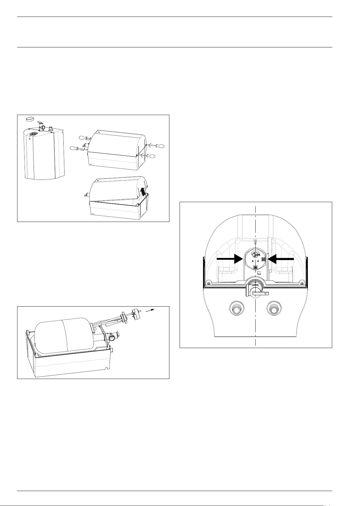
32 | SHC 2.5 / SHC 4 www.stiebel-eltron-usa.com
INSTALLATION
Instructions relatives à l’entretien
12.4 Retrait du couvercle
1. Retirez le bouton de contrôle de la température à
l’avant de l’appareil.
2. Retirez les vis du couvercle.
3. Retirez le couvercle en inclinant la partie inférieure
et enlevez le couvercle. Le couvercle devrait sortir
facilement.
D0000034990
12.5 Retrait de l’élément chauffant
1. Débranchez et vidangez le chauffe-eau (Voir 12.3, «
Vidange du chauffe-eau», p. 31).
2. Retirez le couvercle (Voir 12.4, « Retrait du cou-
vercle», p. 32).
3. Débrancher les fils de la ligne du thermostat .
4. Retirez le thermostat de l’élément de chauffage.
5. Dévissez, à l’aide d’une clé appropriée, l’élément
chauffant.
6. Retirez l’élément chauffant du réservoir.
D0000034991
12.6 Détartrage de l’élément chauffant
Le tartre accumulé peut nuire à la capacité de chauffage
de l’élément chauffant. Le tartre peut même entraîner la
défaillance permanente de l’élément. L’élément peut être
détartré chimiquement ou manuellement.
1. Retirez l’élément chauffant (Voir 12.5, « Retrait de
l’élément chauffant», p. 32).
2. Pour détartrer chimiquement, trempez l’élément
chauffant dans du vinaigre blanc ou toute autre solu-
tion de détartrage, puis rincez abondamment.
3. Pour détartrer manuellement, utilisez un outil non
métallique (doux); brossez l’élément pour enlever le
tartre. Veillez à ne pas endommager la surface de
l’élément chauffant.
4. Remettez l’élément chauffant en place.
5. Remplissez le réservoir avant de rebrancher le
chauffe-eau à l’alimentation électrique.
12.7 Remplacement de l’élément chauffant
1. Débranchez et vidangez le chauffe-eau (Voir 12.3, «
Vidange du chauffe-eau», p. 31).
2. Retirez le couvercle (Voir 12.4, « Retrait du cou-
vercle», p. 32).
3. Retirez l’élément chauffant (Voir 12.5, « Retrait de
l’élément chauffant», p. 32).
4. Installez et étanchez le nouvel élément. Veillez à
ce que l’élément chauffant soit bien positionné.
Fixez à nouveau tous les câbles à leur emplacement
d’origine.
D0000036026
12.8 Remplacement de l’anode
Une anode au magnésium est utilisée pour prolonger la
durée de vie du réservoir. Le retrait permanent de cette
anode pour quelle raison que ce soit annulera la garantie.
Selon les circonstances, l’anode au magnésium aura besoin
d’être changée tous les un ou deux ans. La corrosion galva-
nique ou électrolytique peut détruire un réservoir une anode
usée. La présence d’eau rouillée signale normalement que
l’anode est usée.
1. Débranchez et vidangez le chauffe-eau (Voir 12.3, «
Vidange du chauffe-eau», p. 31).
2. Retirez le couvercle (Voir 12.4, « Retrait du cou-
vercle», p. 32).
3. Retirez l’élément chauffant (Voir 12.5, « Retrait de
l’élément chauffant», p. 32).
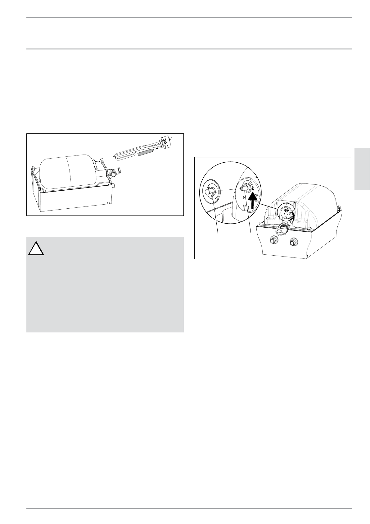
FRANÇAIS
www.stiebel-eltron-usa.com SHC 2.5 / SHC 4 | 33
INSTALLATION
Instructions relatives à l’entretien
4. Retirez l’anode du support de l’élément chauffant dé-
posé en la dévissant.
5. Mettez une nouvelle anode dans support de l’élément
chauffant déposé.
6. Remettez tous les câbles et l’élément chauffant en
place.
7. Remplissez le chauffe-eau d’eau et vérifiez qu’il n’y
a pas de fuite avant de rebrancher à l’alimentation
électrique.
D0000034992
12.9 Vanne d’isolement de sécurité
!
AVERTISSEMENT :
NE BLOQUEZ JAMAIS LE PLONGEOIR COULISSANT
DE RÉ-ENCLENCHEMENT.
DANGER :
DES TEMPÉRATURES DE L’EAU SUPÉRIEURES À 52
°C (125 °F) PEUVENT PROVOQUER DES BRÛLURES
GRAVES, VOIRE MORTELLES EN CAS D’ÉBOUILLAN-
TAGE. N’ESSAYEZ PAS DE RÉENCLENCHER L’IN-
TERRUPTEUR DE LIMITE SUPÉRIEURE SANS AVOIR
LAISSÉ REFROIDIR L’EAU QUI SE TROUVE DANS LE
CHAUFFE-EAU.
12.9.1 Ré-enclenchement du système de coupure en
cas de haute température
1. Débranchez le chauffe-eau.
2. Retirez le couvercle (Voir 12.4, « Retrait du cou-
vercle», p. 32).
3. Débranchez l’adaptateur de l’axe du dispositif de
commande.
4. Appuyez sur le bouton à l’aide d’un outil approprié.
5. Remettez l’adaptateur en position correcte.
6. Remettez le couvercle sur le chauffe-eau et serrez.
7. Remettez le bouton de commande du thermostat en
place.
1 2
1. Adaptateur
2. Bouton
34 | SHC 2.5 / SHC 4 www.stiebel-eltron-usa.com
GARANTIE
Garantie Limitée
13. Garantie Limitée
Sous réserve du respect des termes et conditions définis dans la présente garantie à vie limitée, Stiebel Eltron, Inc. (ci-
après, le « Fabricant ») garantit à l’acheteur d’origine (ci-après le « Propriétaire ») que tous les chauffe-eau Mini-Tank
(ci-après, le « Chauffe-eau ») ne doit pas (i) des fuites dues à des défauts de matériaux ou de fabricant de fabrication
pendant une période de six (6) ans à compter de la date d’achat ou (ii) l’échec en raison de défauts dans les matériaux ou
de fabrication du fabricant pour une période de deux (2) ans à compter de la date d’achat. Le seul et unique recours du
propriétaire dans le cadre de la garantie susmentionnée sera pour le Propriétaire de soit réparer en usine, soit remplacer
le Chauffe-eau défectueux (à la discrétion du fabricant) avec soit un appareil de rechange, soit une ou des pièces ayant les
mêmes caractéristiques d’exploitation. La responsabilité financière maximale du Fabricant ne pourra en aucun cas aller
au-delà du prix d’achat du réservoir.
Cette garantie limitée représente la seule garantie accordée par le fabricant et annule toute les autres garanties, orales
ou écrites, expresses ou implicites, y compris, mais sans y être limitées les garanties de qualité marchande ou d’aptitude
à un usage particulier. Le fabricant rejette toute responsabilité pour les dommages ou frais indirects, consécutifs ou
autres résultant directement ou indirectement de tout vice présent dans le chauffe-eau ou survenu lors de l’usage du
Chauffe-eau. Le fabricant rejette toute responsabilité pour tout dégât des eaux ou tout autre dégât matériel encouru par le
propriétaire, résultant directement ou indirectement de tout vice présent dans le Chauffe-eau ou survenu lors de l’usage
du Chauffe-eau. Seul le Fabricant est autorisé à énoncer les garanties au nom du Fabricant et aucune déclaration, garantie
ou autre document énoncé par une tierce partie ne saurait engager la responsabilité du Fabricant.
Le Fabricant rejette toute responsabilité pour tout dommage causé par ou en relation avec :
1. toute mauvaise utilisation ou négligence du Chauffe-eau, tout accident subi par le Chauffe-eau, toute modification du
Chauffe-eau ou tout autre usage non prévu,
2. les calamités naturelles ou toute autre circonstance sur laquelle le Fabricant n’a aucun contrôle,
3. l’installation du Chauffe-eau autre que conformément aux directives du Fabricant et autre que conformément aux
codes de la construction en vigueur,
4. le non-respect des procédures d’entretien du Chauffe-eau ou l’utilisation du Chauffe-eau non conformes aux directives
du Fabricant,
5. l’utilisation du Chauffe-eau avec une pression d’eau irrégulière ou excessive ou dans le cas où le Chauffe-eau serait
alimenté en eau non potable pour toute durée que ce soit,
6. une installation incorrecte ou l’utilisation de matériaux incorrects par un installateur et sans relation avec les vices de
fabrication ou de matériel du Fabricant,
7. déplacer le Chauffe-eau de son lieu d’installation d’origine;
8. l’exposition au gel,
9. problèmes de qualité de l’eau comme l’eau corrosive, l’eau dure et de l’eau contaminée par des polluants ou des
additifs,
10. pas alimenter en continu l’unité avec de l’eau, également connu comme « le tir à sec ».
Si le Propriétaire désire renvoyer le Chauffe-eau au fabricant pour qu’il soit réparé ou remplacé dans le cadre de cette
garantie, le Propriétaire doit d’abord obtenir l’autorisation écrite du Fabricant. Le Propriétaire doit apporter la preuve
d’achat, y compris la date d’achat, et sera responsable de tous les frais de transport et de dépose. Si le Propriétaire ne peut
pas apporter la preuve de la date d’achat, cette garantie sera limitée à la période commençant à la date de fabrication
estampée sur le Chauffe-eau. Le Fabricant se réserve le droit de rejeter toute couverture de la garantie à la suite d’une
inspection du Chauffe-eau par le Fabricant. Cette garantie ne s’applique qu’au Propriétaire et ne peut pas être transférée.
Certains États et Provinces n’autorisent pas l’exclusion ou la limitation de certaines garanties. Dans ce cas, les limites ci-
mentionnées peuvent ne pas s’appliquer au Propriétaire. Dans ce cas, la garantie sera limitée à la période la plus courte et
aux dommages et intérêts les plus faibles autorisés par la loi. Cette Garantie vous octroie des droits légaux spécifiques. Il
est toutefois possible que vous ayez d’autres droits en fonction de votre juridiction.
Le Propriétaire sera responsable de tous les frais de main-d’œuvre et autres encourus lors de la dépose ou de la
réparation du Chauffe-eau sur le chantier. Veuillez également noter que le Chauffe-eau doit être installé de sorte qu’en cas
de fuite, l’eau qui s’écoule doit couler de façon à ne pas endommager l’endroit où il est installé.
STIEBEL ELTRON, Inc.
17 West Street
West Hatfield, MA 01088, USA
Téléphone: 800.582.8423 ou 413.247.3380
Fax: 413.247.3369
Courriel: info
@
stiebel-eltron-usa.com
www.stiebel-eltron-usa.com
Cette Garantie est valable pour U.S.A. et Canada
uniquement. Garanties peuvent varier selon les pays. S’il
vous plaît consulter votre représentant Eltron Stiebel local
pour la Garantie de votre pays.

www.stiebel-eltron-usa.com SHC 2.5 / SHC 4 | 35
NOTES | NOTAS

Subject to errors and technical changes! Stand 8643
STIEBEL ELTRON, Inc.
17 West Street | 01088 West Hatfield MA
Tel. 0413 247-3380 | Fax 0413 247-3369
www.stiebel-eltron-usa.com
A 304662-38483-9031
4<AMHCMO=aeggcc>