Loading ...
Loading ...
Loading ...
WARNING – SERVICING TO BE CARRIED OUT ONLY BY AN AUTHORISED PERSON
Disconnect from electricity before servicing. Check appliance is safe when you have nished.
34
5 Ovens
5.1 To Remove an Oven Thermostat
DISCONNECT FROM THE ELECTRICITY SUPPLY.
Remove the right-hand hotplate tray (see 2.1); for the
left-hand oven remove the left-hand side panel (see
1.2). Open the appropriate oven door.
Unclip the thermostat phial from the clips at the
front of the oven roof. Disconnect tubing nut at rear
of thermostat and remove the screw(s) securing the
thermostat to the gas rail. Remove thermostat and
gasket/seal. When tting replacement thermostat use
the new gasket/seal supplied.
Make sure that the capillary is clipped to the bracket at
the front of the oven roof.
Reassemble in the reverse order. Check the appliance is
gas sound. Check the operation of the thermostat.
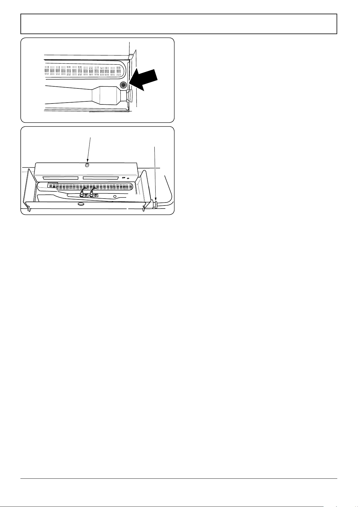
5.2 To Remove the Oven Burner
Open the oven door and remove the oven shelves.
Remove the securing screw at the right-hand end
(Fig.9-7). The burner is held in place by dimples in
the mounting bracket. Slide the burner to the left
and lift up, taking care not to disturb or damage the
2electrodes.
Reassemble in reverse order. Check the 2 electrodes
have not been disturbed.
5.3 To Change the Oven Burner Assembly
Open the oven door. Disconnect the tube nut and
tubing. Remove the screw holding the oven burner
assembly and withdraw complete assembly (Fig.9-8).
Remove the oven burner.
Fit the oven burner to new assembly. Replace the
complete assembly in the oven. Reconnect the tube and
secure with the tube nut.
Check the appliance is gas sound. Check the ame
safeguard device operation
5.4 To Change the Oven Burner Injector
Remove the oven burner (see 5.2). The injector is now
accessible. Remove the old jet and t the new one.
Reassemble in reverse order. Check that the ame
safeguard device probe has not been disturbed.
5.5 To Change an Oven Programming Flame
Safeguard unit
DISCONNECT FROM THE ELECTRICITY SUPPLY.
Pull the cooker forwards to gain access to the cover box
at the rear of the cooker. See ‘Moving Your Cooker’ in the
Installation section.
Remove the screws securing the cover and lift clear.
Noting their positions, pull o all the leads to the PFS
control unit. Slacken the 3 screws holding the control
unit to the cooker and remove.
Oven burner assembly xing screw
Tube nut
Fig.9-8
Fig.9-7
Loading ...
Loading ...
Loading ...