
Please read this installation manual completely before installing the product.
Installation work must be performed in accordance with the national wiring
standards by authorized personnel only.
Please retain this installation manual for future reference after reading it
thoroughly.
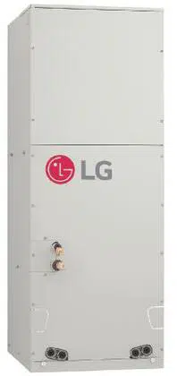
Vertical Air Handling Unit
INSTALLATION MANUAL
AIR
CONDITIONER
MFL67206513
Rev.01_061319
Copyright © 2016 - 2019 LG Electronics Inc. All Rights Reserved.
www.lg.com
www.lghvac.com
ENGLISH FRANÇAIS ESPAÑOL
2 Vertical Air Handling Unit
IMPORTANT!
CAUTION
:
Improper installation, adjustment, alteration, service or maintenance can void the warranty.
The weight of the condensing unit requires caution and proper handling procedures when lifting
or moving to avoid personal injury. Use care to avoid contact with sharp or pointed edges.
Safety Precautions
• Always wear safety eye wear and work gloves when installing equipment.
• Never assume electrical power is disconnected. Check with meter and equipment.
• Keep hands out of fan areas when power is connected to equipment.
• R-410A causes frostbite burns.
• R-410A is toxic when burned.
NOTE TO INSTALLING DEALER: The Owners Instructions and Warranty are to be given to the owner
or prominently displayed near the indoor Furnace/Air Handler Unit.
When wiring:
Electrical shock can cause severe personal injury or death. Only a qualified,
experienced electrician should attempt to wire this system.
• Do not supply power to the unit until all wiring and tubing are completed or reconnected and checked.
• Highly dangerous electrical voltages are used in this system. Carefully refer to the wiring diagram and these
instructions when wiring. Improper connections and inadequate grounding can cause accidental injury or death.
• Ground the unit following local electrical codes.
•
•
Connect all wiring tightly. Loose wiring may cause overheating at connection points and a possible fire hazard.
The choice of materials and installations must comply with the applicable local/national or international standards.
When transporting:
Be careful when picking up and moving the indoor and outdoor units. Get a partner to help, and
bend your knees when lifting to reduce strain on your back. Sharp edges or thin aluminum fins on
the air conditioner can cut your finger.
When installing...
... in a wall: Make sure the wall is strong enough to hold the unit's weight.
It may be necessary to construct a strong wood or metal frame to provide added support.
... in a room: Properly insulate any tubing run inside a room to prevent "sweating" that can cause
dripping and water damage to wall and floors.
... in moist or uneven locatinons: Use a raised concrete pad or concrete blocks provide a solid,
level foundation for the outdoor unit. This prevents water damage and abnormal vibration.
... in an area with high winds: Securely anchor the outdoor unit down with bolts and a metal
frame. Provide a suitable air baffle.
... in a snowy area(for Heat Pump Model): Install the outdoor unit on a raised platform that is
higher than drifting snow. Provide snow vents.
When connecting refrigerant tubing
• Keep all tubing runs as short as possible.
• Use the flare method for connecting tubing.
• Check carefully for leaks before starting the test run.
When servicing
• Turn the power OFF at the main power box(mains) before opening the unit to check or repair
electrical parts and wiring.
• Keep your fingers and clothing away from any moving parts.
• Clean up the site after you finish, remembering to check that no metal scraps or bits of wiring have
been left inside the unit being serviced.
• Installation or repairs made by unqualified persons can result in hazards to you and others.
Installation of all field wiring and components MUST conform with local building codes or, in the absence of local
codes, with the National Electrical Code 70 and the National Building Construction and Safety Code or Canadian
Electrical code and National Building Code of Canada.
• The information contained in the manual is intended for use by a qualified service technician familiar with safety
procedures and equipped with the proper tools and test instruments.
• Failure to carefully read and follow all instructions in this manual can result in equipment malfunction, property
damage, personal injury and/or death.
Please read this instruction sheet completely before installing the product.
This air conditioning system meets strict safety and operating standards. As the installer or service person,
it is an important part of your job to install or service the system so it operates safely and efficiently.
WARNING
!
Special warnings
!

Installation Manual 3
ENGLISH
Vertical Air Handling Unit Installation Manual
TABLE OF CONTENTS
o Four type "A" screws
o Pipes: Gas side
Liquid side (Refer to
Product Data)
o Insulation materials
o Additional drain pipe
o Level gauge
o Screw driver
o Electric drill
o Hole core drill
o Hexagonal wrench
o Gas-leak detector
o Vacuum pump
o Gauge manifold
Safety Precautions...............................4
Features ................................................6
Duct Connection Dimensions .............7
Installation ............................................8
Selection of the best location .............8
Upflow Installation ..............................9
Downflow Installation........................10
Horizontal-Right Installation .............12
Duct work .........................................13
Horizontal-left Installation .................14
Combination indoor units
(Multi Zone) ......................................15
Flaring work......................................16
Connection of piping - Indoor,
Outdoor, BD Unit ..............................17
Plumbing materials and storage
methods............................................18
Insulation ..........................................19
Condensate Drain ............................20
Wiring Connection ............................22
Remote controller installation ..........24
Wired remote controller installation ..26
3rd Party Thermostat.........................27
Internal Electric Heater(Accessory) .28
DIP Switch Setting of Indoor unit
PCB .....................................................29
Product Data.......................................30
Minimum airflow by heater capacity
.....30
Installation Requirements
Required Parts Required Tools
Safety Precautions
4 Vertical Air Handling Unit
Safety Precautions
To prevent injury to the user or other people and property damage, the following instructions must be followed.
n Be sure to read before installing the air conditioner.
n Be sure to observe the cautions specified here as they include important items related to safety.
n Incorrect operation due to ignoring instruction will cause harm or damage. The seriousness is classified by the
following indications.
n Meanings of symbols used in this manual are as shown below.
This symbol indicates the possibility of death or serious injury.
This symbol indicates the possibility of injury or damage to properties only.
Be sure not to do.
Be sure to follow the instruction.
n Installation
Do not use a defective or
underrated circuit breaker.
Use this appliance on a
dedicated circuit.
• There is risk of fire or electric
shock.
For electrical work, contact
the dealer, seller, a qualified
electrician, or an Authorized
Service Center.
• Do not disassemble or repair
the product. There is risk of
fire or electric shock.
Always ground the product.
• There is risk of fire or electric
shock.
Install the panel and the
cover of control box securely.
• There is risk of fire or electric
shock.
Always install a dedicated
circuit and breaker.
• Improper wiring or installation
may cause fire or electric
shock.
Use the correctly rated
breaker or fuse.
• There is risk of fire or electric
shock.
Do not modify or extend the
power cable.
• There is risk of fire or electric
shock.
Do not let the air conditioner
run for a long time when the
humidity is very high and a
door or a window is left open.
• Moisture may condense and
wet or damage furniture.
Be cautious when unpacking
and installing the product.
• Sharp edges could cause
injury. Be especially careful of
the case edges and the fins
on the condenser and
evaporator.
WARNING
CAUTION
!
!
WARNING
!
ENGLISH
Safety Precautions
Installation Manual 5
n Installation
Always check for gas
(refrigerant) leakage after
installation or repair of product.
• Low refrigerant levels may
cause failure of product.
Install the drain hose to
ensure that water is drained
away properly.
• A bad connection may cause
water leakage.
Keep level even when
installing the product.
• To avoid vibration or water
leakage.
Do not install product where
noise or air flow from the
outdoor unit could disturb
neighbors.
• It may cause a problem for your
neighbors.
Use two or more people to lift
and transport the product.
• Avoid personal injury.
Do not install the product
where it will be exposed to
sea wind (salt spray) directly.
• It may cause corrosion on the
product. Corrosion, particularly on
the condenser and evaporator
fins, could cause product
malfunction or inefficient
operation.
Safely dispose of the packing materials.
• Packing materials, such as nails and other metal or wooden parts, may cause stabs or other injuries.
• Tear apart and throw away plastic packaging bags so that children may not play with them. If children play
with a plastic bag which was not torn apart, they face the risk of suffocation.
n Operation
For installation, always
contact the dealer or an
Authorized Service Center.
• There is risk of fire, electric
shock, explosion, or injury.
Do not install the product on
a defective installation stand.
• It may cause injury, accident,
or damage to the product.
Be sure the installation area
does not deteriorate with age.
• If the base collapses, the air
conditioner could fall with it,
causing property damage,
product failure, and personal
injury.
Do not store or use flammable gas or combustibles near the product.
• There is risk of fire or failure of product.
Use a vacuum pump or Inert (nitrogen) gas when doing leakage test or air purge. Do not compress air or
Oxygen and do not use Flammable gases. Otherwise, it may cause fire or explosion.
• There is the risk of death, injury, fire or explosion.
CAUTION
!
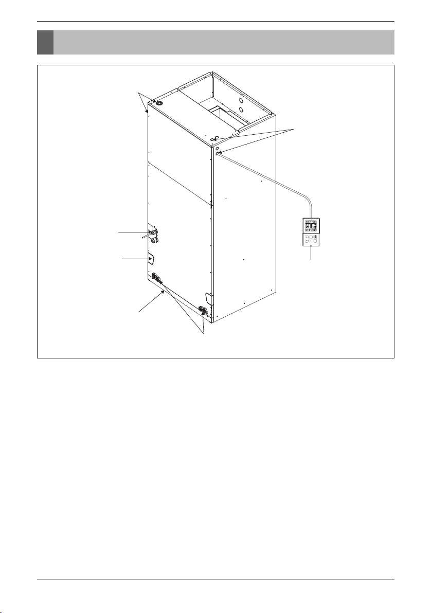
Features
6 Vertical Air Handling Unit
Wiring knockouts
for conduit
Wiring knockouts
for conduit
Refrigerant
connections
Drain connections
for horizontal
application
Filter access
Drain connections for
upflow application
TEMP
FAN
SPEED
OPER
MODE
Wired Remote
Controller
(Accessory)
Features
Features
ENGLISH
Installation Manual 7
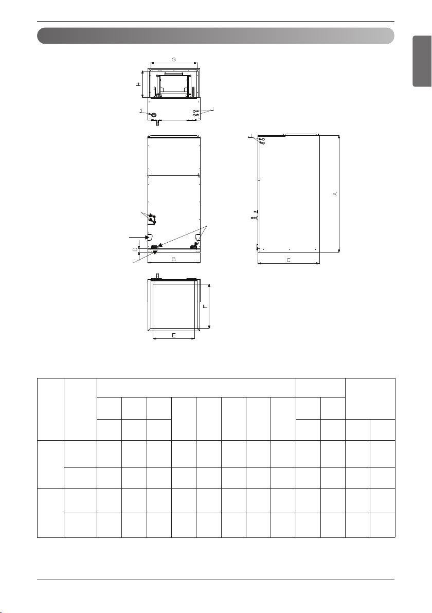
Duct Connection Dimensions
<Top>
<Front>
<Bottom>
<Side-right>
Refrigerant
connections
Drain connections
for horizontal
application
Drain
connections
for upflow
application
Air filter cover
(Unit: inch(mm))
ODU
Capacity
(kBtu/h)
Dimensions
Wiring
Knock out
Refrigerant
Connections
Pipe size
A B C
D E F G H
I J
Height Width Depth Power
Commu
nication
Liquid Gas
Single
Zone
18
24
36
48-5/8
(1 236)
18
(457)
21-1/4
(540)
1-9/16
(40)
17-1/2
(445)
20
(530)
17
(432)
12-1/8
(308)
1-11/16
(43)
7/8
(22)
3/8
(9.52)
5/8
(15.88)
42
48
55-3/16
(1 401)
25
(635)
21-1/4
(540)
1-9/16
(40)
24-1/2
(623)
20
(530)
24
(610)
12-1/8
(308)
1-11/16
(43)
7/8
(22)
3/8
(9.52)
5/8
(15.88)
Multi
Zone
18
24
48-5/8
(1 236)
18
(457)
21-1/4
(540)
1-9/16
(40)
17-1/2
(445)
20
(530)
17
(432)
12-1/8
(308)
1-11/16
(43)
7/8
(22)
1/4
(6.35)
1/2
(12.7)
36
48-5/8
(1 236)
18
(457)
21-1/4
(540)
1-9/16
(40)
17-1/2
(445)
20
(530)
17
(432)
12-1/8
(308)
1-11/16
(43)
7/8
(22)
3/8
(9.52)
5/8
(15.88)
Installation
• Where optimum air distribution can be ensured.
• Where nothing blocks air passage and install the duct work.
• Where condensate can be properly drained.
• Where the ceiling is strong enough to bear the indoor unit weight.
• Where the false ceiling is not noticeably on an incline.
• Where sufficient clearance for maintenance and service can be ensured.
• Where piping between indoor and outdoor units is possible within the allowable limit. Refer to the
installation manual for the outdoor unit.
• Vertical Air Handling Unit can be installed for upflow and horizontal-left positions.
NOTE : The primary and secondary drain line must be trapped to allow proper drainage of condensate
water, If the secondary drain line is not used, it must be capped.
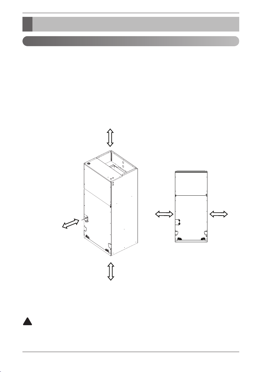
Selection of the best location
More than 600(23-5/8)
clearance from
access panels
for Service
More than
250(9-27/32)
More than
250(9-27/32)
Unit : mm(inch)
More than 350
(13-25/32)
More than 350
(13-25/32)
CAUTION
In the case of sea coast installation, salt residue may cause corrosion of cabinet and component
parts. Please take appropriate anti-corrosion measures.
!
8 Vertical Air Handling Unit
Installation

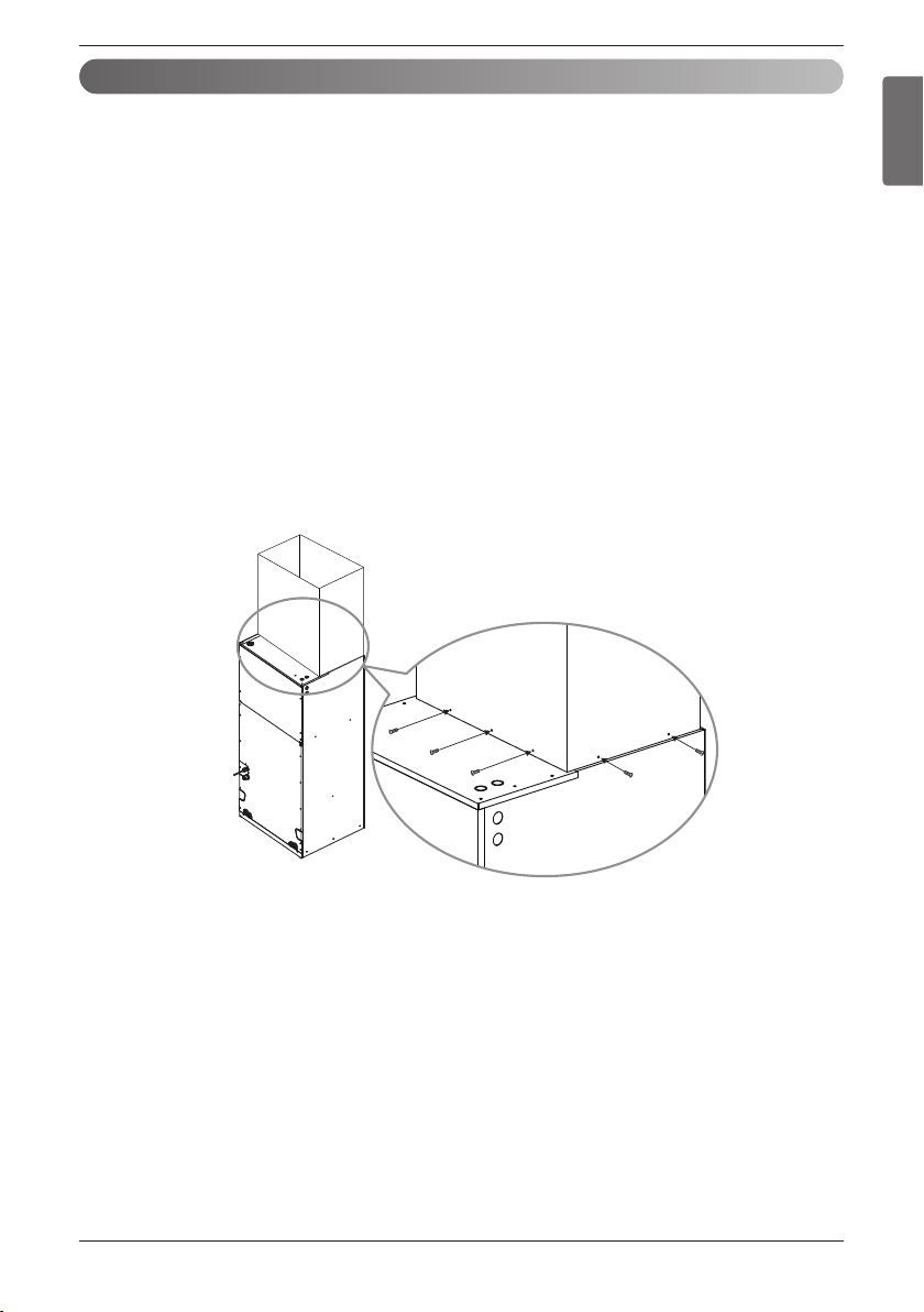
• Position unit for plenum installation.
• The plenum should be secured in order to support the installation of adapter callers accommodate the
installation of any duct work.
• Seal all duct work according to local codes to prevent air leakage. Ensure that filter access is
unobstructed.
• The air handler support platform should be sturdy enough to support the cabinet plus any accessory
components including filter box.
• The minimum height clearance is 14 inches(350 mm) to maintain proper air flow.
• Vibration isolators (purchased locally) must be placed between the unit and the pedestal.
• An illustration showing an example of where a vibration isolator should be added would clarify what
the installing contractor should do to properly position the isolator.
More than 6 screws (M4*25 L)
Field
Supplied Return
Plenum
More than
1 inch (25 mm)
Field Supplied
Supply Duct
Installation
Upflow Installation
CAUTION
Do not connect the screws on Front and Rear side, it may cause the filter can not be mounted.
!
ENGLISH
Installation Manual 9

10 Vertical Air Handling Unit
Installation
Downflow installation requires various changes to the air handling unit from original configuration.
There are additional kits required in order to convert the air handling unit to the downflow configuration.
1) Please remove the panels and Brackets from
the unit.
2) Please remove the thermistor from a coil. Also
remove a coil and Drain pan from the unit
Downflow Installation
D
F
A
B
C
E
Deletion
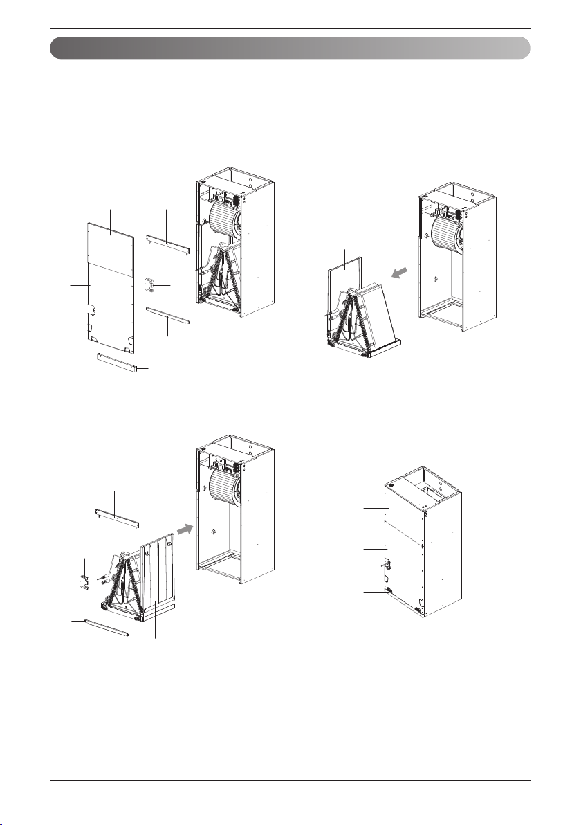
3) Rotate the cabinet. 4) Please assemble the downflow bracket as
below. Install the bracket in the order shown
and fix with screw.
ڸ
ڹ
ں
ڻ
ڼ
ڽ
D
Bracket Installation
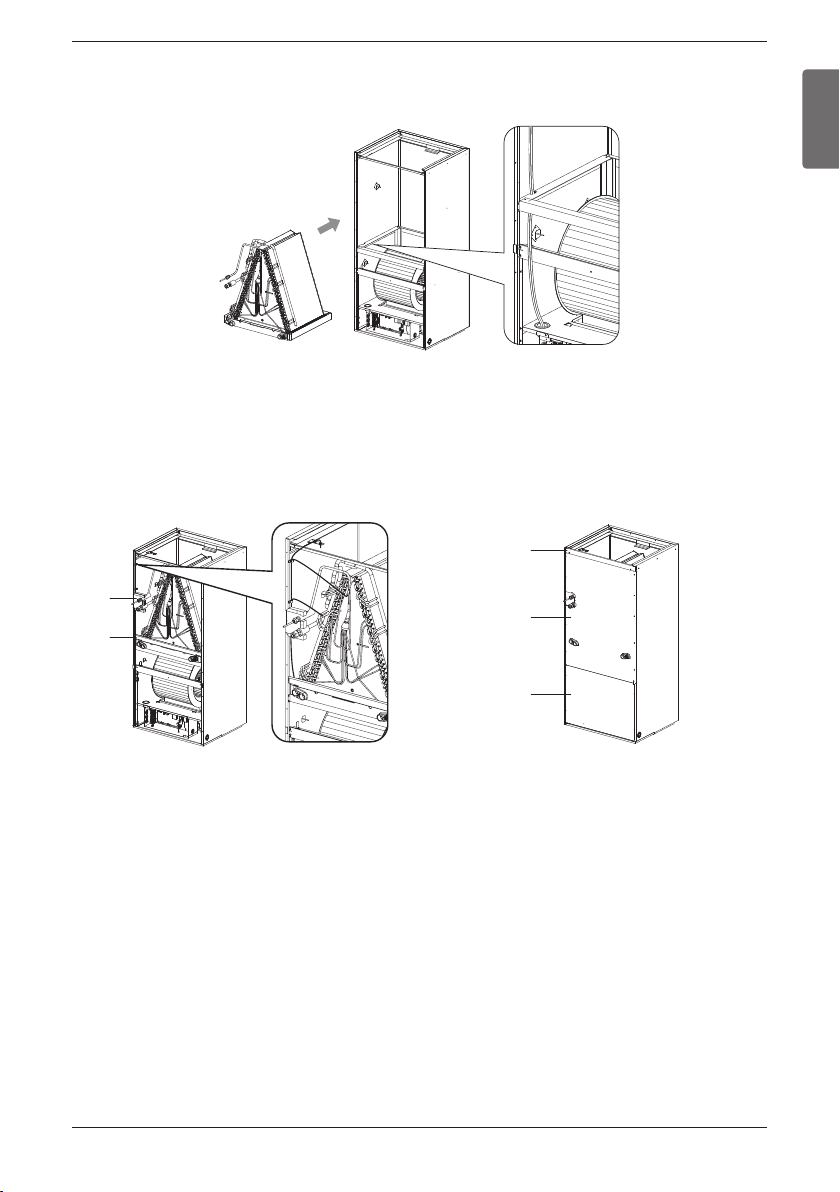
Installation Manual 11
Installation
ENGLISH
5) Reinsert the coil back to the cabinet.
Before this action, please route the thermistor wires into the downflow Bracket
6) The brackets are required to be reattached. 7) Reinstall the new panel.
Room
Eva In
Eva
Out
E
F
C
New
A
12 Vertical Air Handling Unit
Installation
Downflow installation requires various changes to the air handling unit from original configuration.
There are additional kits required in order to convert the air handling unit to the downflow configuration.
Horizontal-Right Installation
1) Please remove the panels and Brackets from
the unit.
2) Please remove the thermistor from a coil. Also
remove a coil and Drain pan from the unit.
D
F
A
B
C
E
G
3) Rotate the drain pan. 4) Reinstall brackets and panel.
D
F
G
E
A
B
C
Installation Manual 13
Installation
ENGLISH
Duct work
• Over 10 screws should be used for joining supply duct with the unit.
• To prevent vibration transmission, exploit flexible connectors between duct and the unit. It is
mandatory that the flexible connector between unit and duct at discharge connection should be made
off heat resistive material when electric heater is installed.
• Duct work must be insulated and covered with vapor barrier when routed through unconditioned
space.
• To prevent the formation of condensation, insulate the duct well.
• Internal acoustical insulation lining may necessary for the metal duct system if it do not have 90°
elbow and 10 ft. of main duct to first branch takeoff.
• It is advised that a fibrous duct work could be used as a substitute if built and installed in accordance
with the most recent edition of SMACNA construction standard on fibrous glass ducts.
• Collectively fibrous duct work and acoustical lining shall obey National Fire Protection Association
standards 90 A or B as tested by UL standard 181 for class 1 air ducts.
• Seal around the delivery duct subsequent to when the duct is secured so that to facilitate prevention
of air leakage.
More than 10 screws
(M4*25 L)
14 Vertical Air Handling Unit
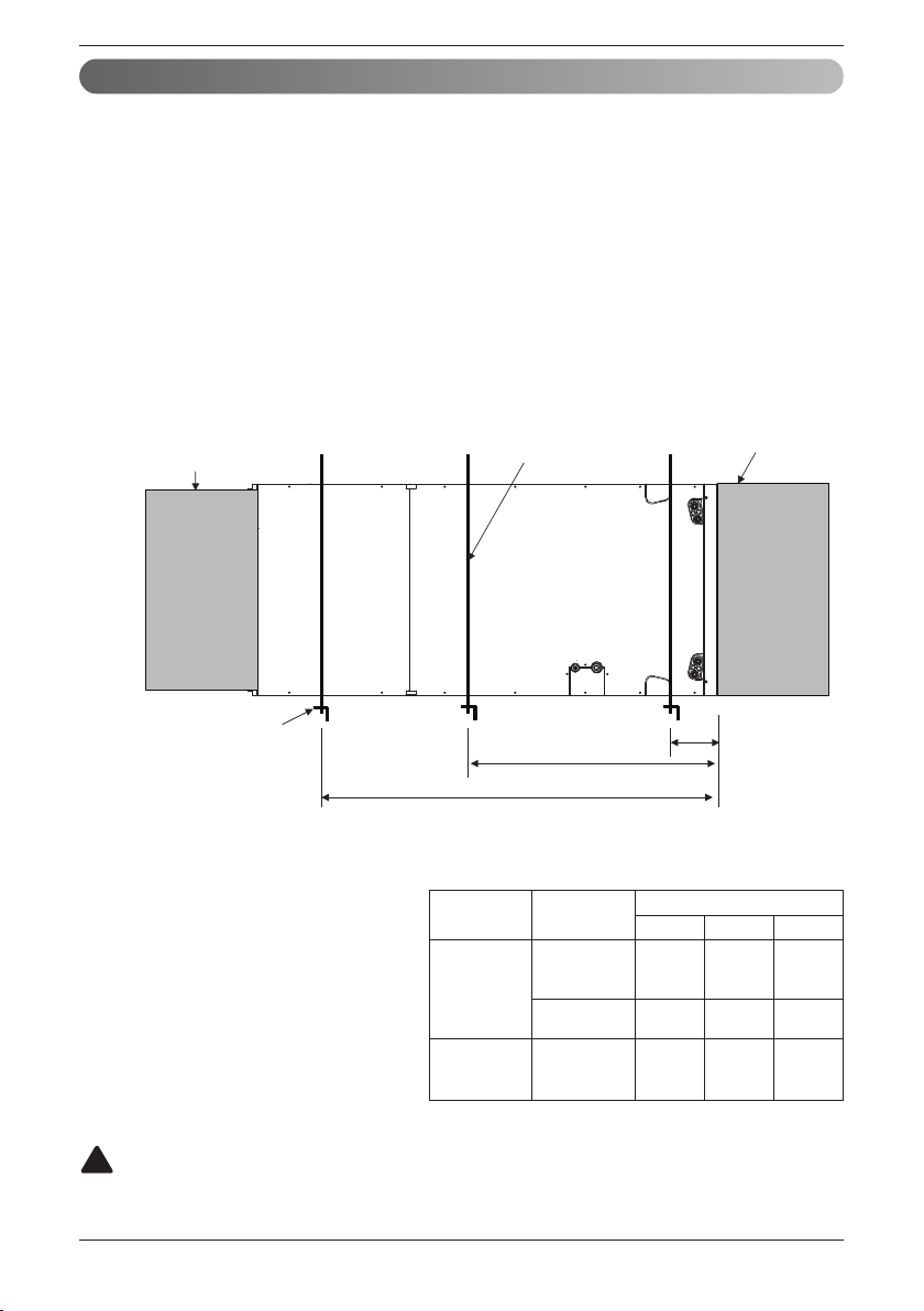
• It is particular that the units should not be installed in such a manner that the access panels facing up
or down
• It should be confirmed that the installation is in accordance with all relevant building codes that may
necessitate installation of external condensate pan.
-Set up a support for unit by locating it in or above external condensate pan.
• Angle steel support brackets with threaded rods which supporting the units from the underside should
be used as shown in the figure below if the units are suspended.
• If not suspended then also it should be supported as same as mentioned above and also carefully
isolated to avoid sound transmission. The size of the support should comparatively bigger than the
unit and the unit must be place at centre of the support.
• Locally available vibration isolators must be placed between the unit and the support.
• The same installation method of up flow type has to be used in the case of Return Plenum and
supply duct.
Horizontal-left Installation
CAUTION
To ensure proper drainage for horizontal installations, unit must be installed so it is within 1/8” level of
the length and width of unit.
!
B
A
C
More than 1-1/2 inch
(38 mm) X 1-1/2 inch (38
mm) angle Recommended
length more than 26
inch(660 mm) with
2 inch(50 mm) clearance
on both sides of unit
More than 3/8 inch
(9.5 mm) threaded rod
Field Supplied
Supply Duct
Field Supplied
Return Plenum
Suspension support locations
(Unit : inch(mm))
Installation
ODU
Capacity
(kBtu/h)
Dimension
ABC
Single
Zone
18
24
36
4(100) 23(580)
41-11/32
(1 050)
42
48
4(100) 29(730) 48(1 220)
Multi
Zone
18
24
36
4(100) 23(580)
41-11/32
(1 050)
Installation Manual 15
ENGLISH
Installation
Combination indoor units (Multi Zone)
:
1. The total capacity(in Btu/h unit) of connected indoor unit models represents the total sum
of the figures expressed in the indoor model name.
2. Combinations in which the total capacity of the connected indoor units exceeds the
capacity of the outdoor unit will reduce the capacity of each indoor unit below the rated
capacity during simultaneous operation. Therefore, if circumstances allows, combine
indoor units within the capacity of the outdoor unit.
3. VAHU, Ceiling Concealed Duct(High Static) type indoor unit’s combination calculation
method as below.
Calculation method for total capacity of connectable indoor unit to an outdoor unit
= (Sum of all VAHU & Ceiling Concealed Duct(High Static) type indoor units capacity
x 1.3) + Sum of all other indoor unit’s capacity
NOTICE
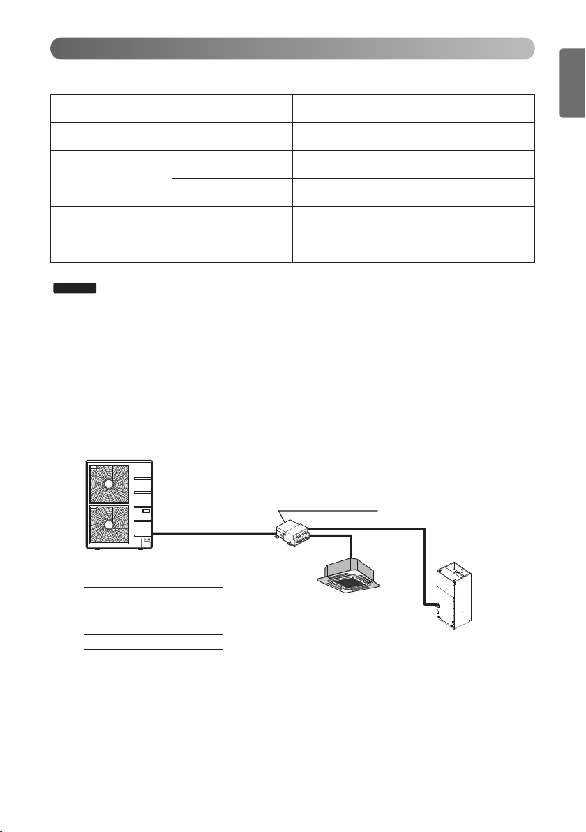
The indoor units connectable to the outdoor unit are shown below
Indoor Unit
Outdoor Unit (kBtu/h)
Type
Capacity
(kBtu/h)
36 54
Vertical
AHU
18 / 24 O O
36 X O
Ceiling Concealed
Duct
(High Static)
24 O O
36 X O
BD unit (PMBD3641)
A8UW54GFA0
[LMU540HV]
Example)
Total rated capacity index : 18 + 36 x 1.3 = 64.8 < 73
4Way CST
AMNW18GTQA0
[LMCN185HV]
VAHU
AMNW36GNJA0
[LMVN360HV]
Outdoor Unit
(kBtu/h)
Total capacity
of connectable
indoor units (kBtu/h)
36 48
54 73
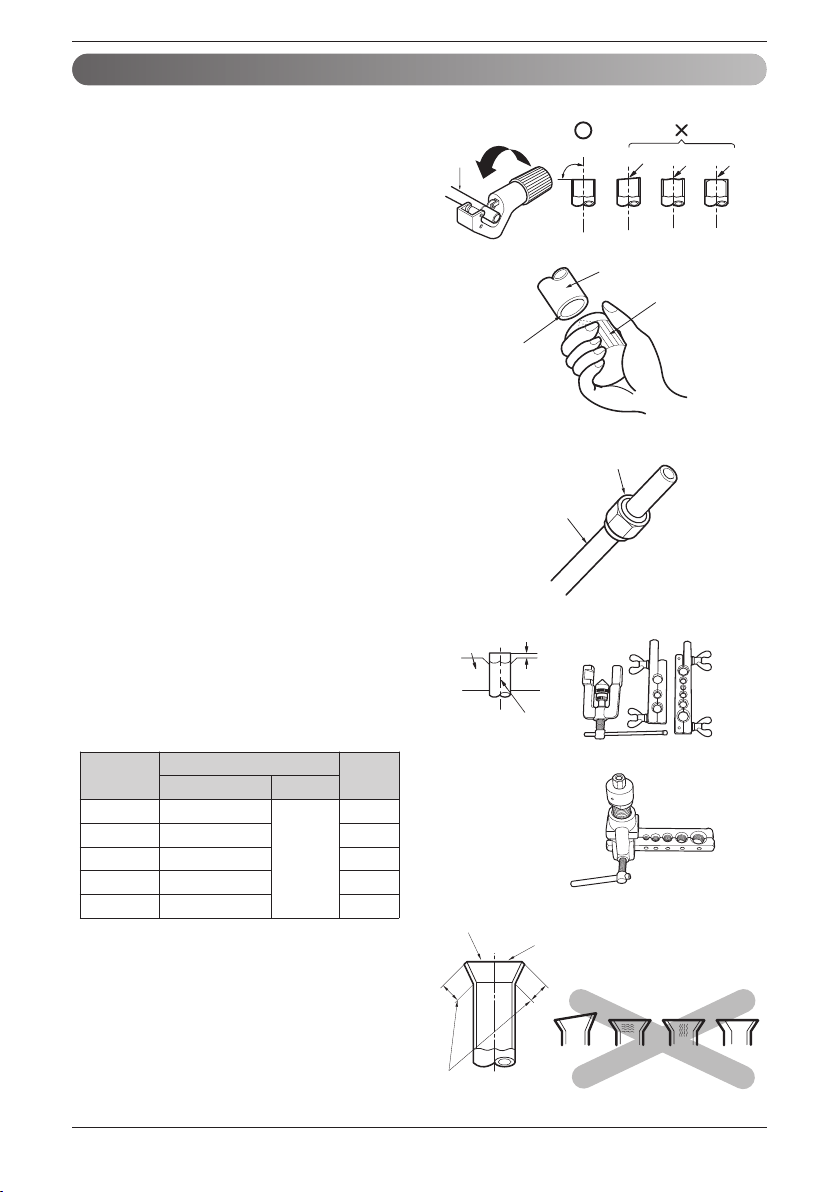
Flaring work
Main cause of gas leakage is defect in
flaring work. Carry out correct flaring work
in the following procedure.
1) Cut the pipes
n Use the accessory piping kit or the
pipes purchased locally.
n Measure the distance between the
indoor and the outdoor unit.
n Cut the pipes a little longer than
measured distance.
n Cut the cable 1.5 m(4.9 ft) longer than
the pipe length.
2) Burrs removal
n Completely remove all burrs from the
cut cross section of pipe/tube.
n Put the end of the copper tube/pipe to
downward direction as you remove
burrs in order to avoid to let chips drop
in the tubing.
3) Putting nut on
n Remove flare nuts attached to indoor
and outdoor units, than put them on
pipe/tube having completed burr
removal.
(Not possible to put them on after
flaring work)
4) Flaring work
n Carry out flaring work using flaring tool
as shown below.
Firmly hold copper tube in a bar(or die)
as indicated dimension in the table
above.
5) Check
n Compare the flared work with figure.
n If flare is noted to be defective, cut off
the flared section and do flaring work
again.
Copper
tube
90°
Slanted Uneven Rough
Pipe
Reamer
Point down
Flare nut
Copper tube
Inclined
Inside is shining without scratches.
Smooth all round
Even length
all round
Surface
damaged
Cracked Uneven
thickness
= Improper flaring =
Bar
Copper pipe
"A"
<Wing nut type>
<Clutch type>
16 Vertical Air Handling Unit
Installation
Pipe diameter
Inch (mm)
A Inch (mm)
Thickness
Inch (mm)
Wing nut type
Clutch type
Ø 1/4 (Ø 6.35)
0.04~0.05 (1.1~1.3)
0~0.02
(0~0.5)
0.03 (0.7)
Ø 3/8 (Ø 9.52)
0.06~0.07 (1.5~1.7)
0.03 (0.8)
Ø 1/2 (Ø 12.7)
0.06~0.07 (1.6~1.8)
0.03 (0.8)
Ø 5/8 (Ø 15.88)
0.06~0.07 (1.6~1.8)
0.04 (1.0)
Ø 3/4 (Ø 19.05)
0.07~0.08 (1.9~2.1)
0.04 (1.0)
Installation Manual 17
ENGLISH
Installation
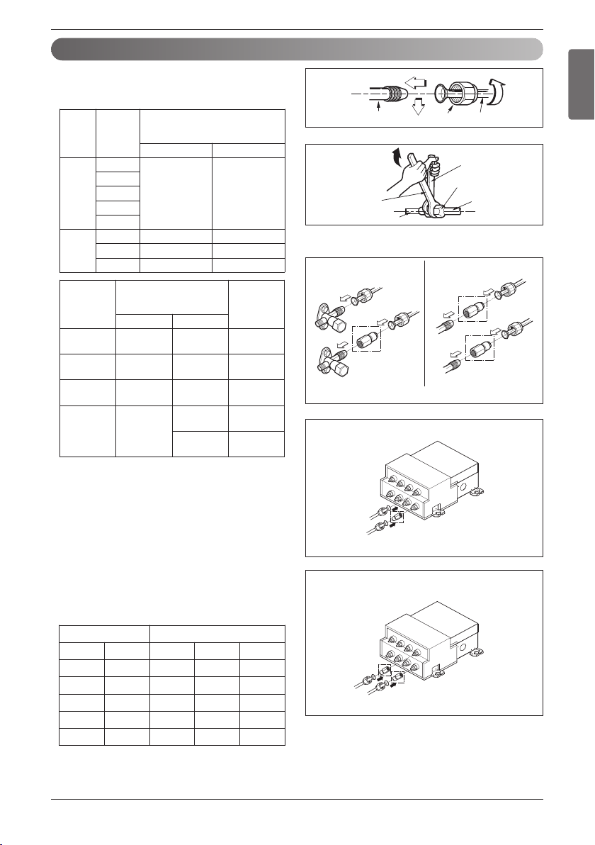
Connection of piping - Indoor, Outdoor, BD Unit
Finally, tighten the flare nut with torque wrench
until the wrench clicks.
• When tightening the flare nut with torque
wrench ensure the direction for tightening
follows the arrow on the wrench.
Align the center of the piping and sufficiently
tighten the flare nut by hand.
(only indoor units
36 kBtu/h connect “D ROOM”)
A ROOM
B ROOM
C ROOM
D ROOM
(Only indoor units
18/24 kBtu/h)
A ROOM
B ROOM
C ROOM
D ROOM
Indoor unit tubing Flare nut Pipes
Torque Wrench
Indoor unit tubing
Open-end wrench (fixed)
Connection pipe
Flare nut
(Only Indoor Units 18/24 kBtu/h)
ODU IDU
For Multi Zone
(PMBD3620 / PMBD3630 / PMBD3640)
(PMBD3641)
Outside diameter Torque
mm inch N
.
m kgf
.
m lbf
.
ft
Ø 6.35 1/4 14~18 1.4~1.8 10~13
Ø 9.52 3/8 34~42 3.5~4.3 25~31
Ø 12.7 1/2 49~61 5.0~6.2 36~45
Ø 15.88 5/8 69~82 7.0~8.4 51~60
Ø 19.05 3/4
100~120 10.0~12.2 73~88
BD Unit
Refrigerant Connections
Pipe Size (inch (mm))
Connectable
Indoor Unit
Capacity
(kBtu/h)
Liquid Gas
PMBD3620
1/4 (Ø 6.35)
x 2 EA
3/8 (Ø 9.52)
x 2 EA
18/24
PMBD3630
1/4 (Ø 6.35)
x 3 EA
3/8 (Ø 9.52)
x 3 EA
18/24
PMBD3640
1/4 (Ø 6.35)
x 4 EA
3/8 (Ø 9.52)
x 4 EA
18/24
PMBD3641
1/4 (Ø 6.35)
x 4 EA
3/8 (Ø 9.52)
x 3 EA
18/24
(A/B/C ROOM)
1/2 (Ø 12.7)
x 1 EA
36
(D ROOM)
BD Unit(PMBD3641) includes the sockets.
(Ø 12.7 → Ø 15.88 x 1 EA, Ø 6.35 → Ø 9.52 x 1 EA)
Indoor Unit (18/24k) includes the sockets.
(Ø 9.52 → Ø 6.35 x 1 EA, Ø 15.88 → Ø 12.7 x 1 EA,
Ø 9.52 → Ø 12.7 x 1 EA)
ODU
Capacity
(kBtu/h)
Refrigerant Connections
Pipe size
Liquid Gas
Single
Zone
18
3/8 (Ø 9.52) 5/8 (Ø 15.88)
24
36
42
48
Multi
Zone
18 1/4 (Ø 6.35) 1/2 (Ø 12.7)
24 1/4 (Ø 6.35) 1/2 (Ø 12.7)
36 3/8 (Ø 9.52) 5/8 (Ø 15.88)
18 Vertical Air Handling Unit
3
2
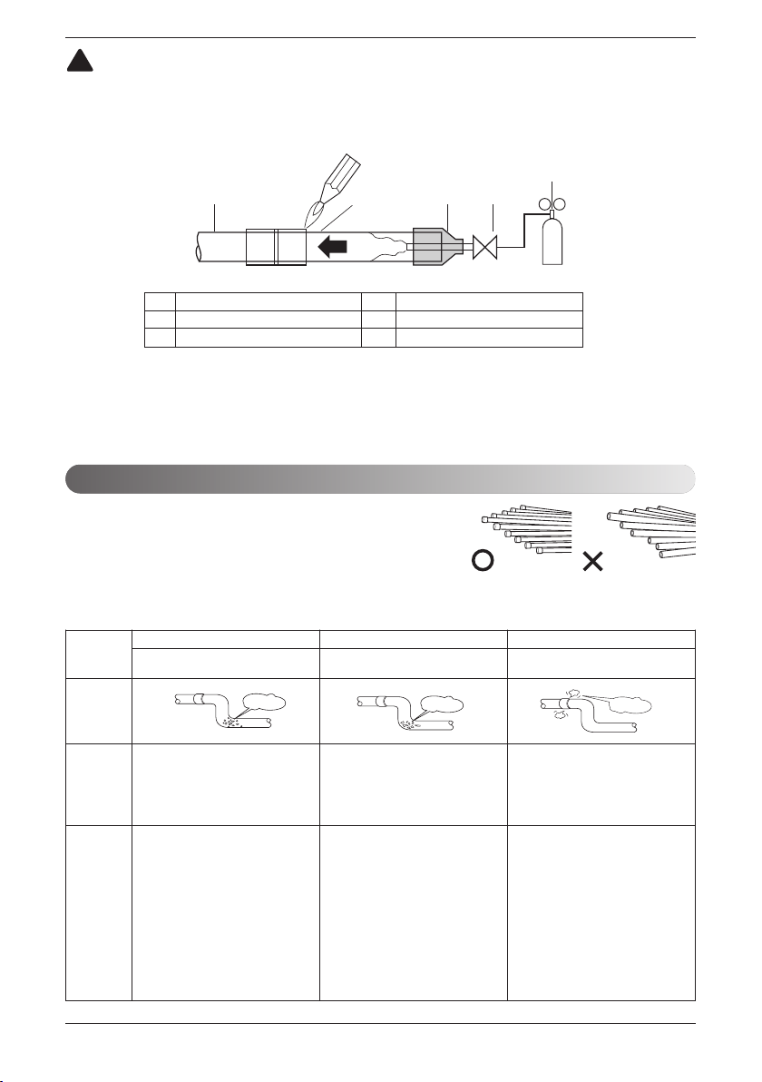
1
45
6
1 Refrigerant piping 4 Taping
2 Pipe to be brazed 5 Valve
3 Nitrogen 6 Pressure-reducing valve
CAUTION
Always blow nitrogen into pipe which is brazed. Always use a non-oxidizing brazing
material for brazing the parts and do not use flux. If not, oxidized film can cause clogging or
damage to the compressor unit and flux can harm the copper piping or refrigerant oil.
!
Note : The torch tip should be positioned at the opposite angle to shop the
correct way to apply heat on the pipe coupling.
Installation
Pipe must be able to obtain the specified thickness and should be used with low
impurities.
Also when handling storage, pipe must be careful to prevent a fracture, deformity
and wound.
Should not be mixed with contaminations such as dust, moisture.
Plumbing materials and storage methods
Refrigerant piping on three principles
Drying Cleanliness Airtight
Should be no moisture
inside
No dust inside.
There is no refrigerant
leakage
Items
Moisture
Dust
Leakage
Cause failure
- Significant hydrolysis of refrigerant oil
- Degradation of refrigerant oil
- Poor insulation of the compressor
- Do not cold and warm
- Clogging of EEV, Capillary
- Degradation of refrigerant oil
- Poor insulation of the compressor
- Do not cold and warm
- Clogging of EEV, Capillary
- Gas shortages
- Degradation of refrigerant oil
- Poor insulation of the compressor
- Do not cold and warm
Countermeas
ure
- No moisture in the pipe
- Until the connection is completed, the
plumbing pipe entrance should be
strictly controlled.
- Stop plumbing at rainy day.
- Pipe entrance should be taken side or
bottom.
- When removal burr after cutting pipe,
pipe entrance should be taken down.
- Pipe entrance should be fitted cap
when pass through the walls.
- No dust in the pipe.
- Until the connection is completed, the
plumbing pipe entrance should be
strictly controlled.
- Pipe entrance should be taken side or
bottom.
- When removal burr after cutting pipe,
pipe entrance should be taken down.
- Pipe entrance should be fitted cap
when pass through the walls.
- Airtightness test should be.
- Brazing operations to comply with
standards.
- Flare to comply with standards.
- Flange connections to comply with
standards.
Installation Manual 19
ENGLISH
Installation
Insulation
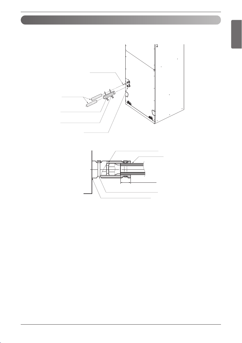
Insulate the joint and tubes completely.
Thermal insullaton : All thermal insulation must comply with local requirement.
Union for liquid pipe
Refrigerant pipe
and thermal
insulator
(Local supply)
Union for gas pipe
Thermal insulator for
refrigerant pipe(Local supply)
Hose crip for thermal insulator
(Local supply)
Make sure that there is no clearance here.
Overlap with thermal
insulator for piping.
Thermal insulator for refrigerant pipe
(Local supply)
Thermal insulator for
piping(Local supply)
Hose clip for thermal insulator(Local supply)
1. Use the heat insulation material for the refrigerant piping which has an excellent heat-resistance
[over 120 °C(248 °F)].
2. Precautions in high humidity circumstance:
This air conditioner has been tested according to the "KS Standard Conditions with Mist" and
confirmed that there is not any default. However, if it is operated for a long time in high humid
atmosphere [dew point temperature: more than 23 °C(73.4 °F)], water drops are liable to fall. In this
case, add heat insulation material according to the following procedure:
• Heat insulation material to be prepared... Adiabatic glass wool with thickness 0.4 inch(10 mm) to 0.8
inch(20 mm).
• Stick glass wool on all air conditioners that are located in a house attic.
20 Vertical Air Handling Unit
Installation
• The drainage performance has to be optimized by installing both primary and secondary drain lines
along with properly sized condensate traps in order to prevent property damage.
• Care should be taken to avoid the blocking of filter access panel while connecting condensate drain
lines. The primary and secondary condensate traps has to be primed after connecting to the drain
pan.
※ A field supplied external condensate pan has to be installed underneath the entire unit if the
unit is above the living space . Other wise damage may result due to condensate over flow.
Also a additional external condensate line should run from unit in to the pan.
• The entire condensate should be drained from the external condensate pan to some noticeable
area. It is advised to install traps in condensate lines as near to the coil as possible. The outlet of
each trap should be below its connection to the condensate pan avert condensate from overflowing
drain pan.
• If located above the living area then all traps should be prime and insulated and also tested for
leakage.
• PVC 3/4 inch(19.05 mm) male pipe thread fitting is advised to use at condensate pan with gentle tight.
• For easy drain flow the drain hose has to be pointed downward.
• Care should be taken to not use pipe joint connection or PVC/CPVC for units drain line connection.
Use only Teflon tape.
• For preventing winter freeze up on condensate line special means should be provided for drainage.
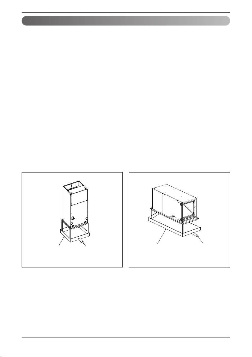
Condensate Drain
Case Ⅰ (Upflow/Downflow)
Case Ⅱ (Right/Left)
Field supplied
drain pan
Drain piping
Field supplied
drain pan
Drain piping
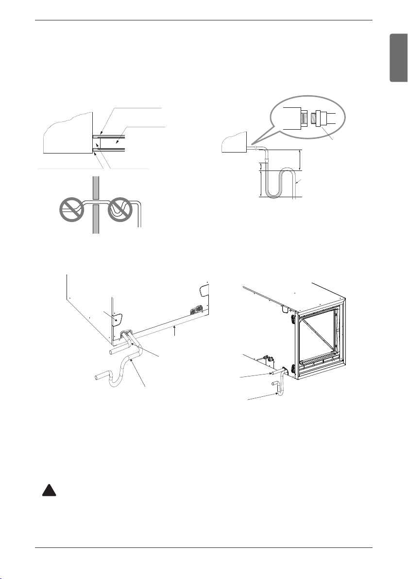
Installation Manual 21
Installation
ENGLISH
Drainage hole
U-Trap
B
C
A ≥
2-3/4 inch
(70 mm)
B ≥ 2C
C ≥ 2 x SP
SP = External Pressure
(in.wc)
Ex) External Pressure
= 0.4 in.wc(10 mmAq)
A ≥
2-9/16 inch(70 mm)
B ≥
1-7/12 inch(40 mm)
C ≥
19/24 inch(20 mm)
A
Make sure to be closed.
Unit
Drainage pipe
(Field supply)
Thermal insulator
(Field supply)
Applied U-Trap Dimension
CORRECT
• Install the U-Trap to prevent
a water leakage caused by the blocking
of intake air filter.
Upflow Drain Horizontal-left Drain
INCORRECT
3/4 inch(19.05 mm)
connector
Air filter cover
Main drain along with suitable trap.
( Field supplied trap with sufficient
depth can be used. P-traps of standard
size are not sufficient. Refer the figure
for recommended condensate trap.)
Supplementary drain
with proper trap. (field
supplied kit can be used)
Horizontal-left Horizontal-left
Drain KnockoutDrain Knockout
Horizontal-left
Drain Knockout
CAUTION
The supplied flexible drain hose should not be strained.
A strained hose may cause leakage of water.
!
GRADIENT OF UNIT AND DRAIN PIPING
• Alway lay the drain with downward inclination(1/50 to 1/100).
Prevent any upward flow or reverse flow in any part.
• 5/24 inch(5 mm) or thicker formed thermal insulator shall always be provided for the drain pipe.
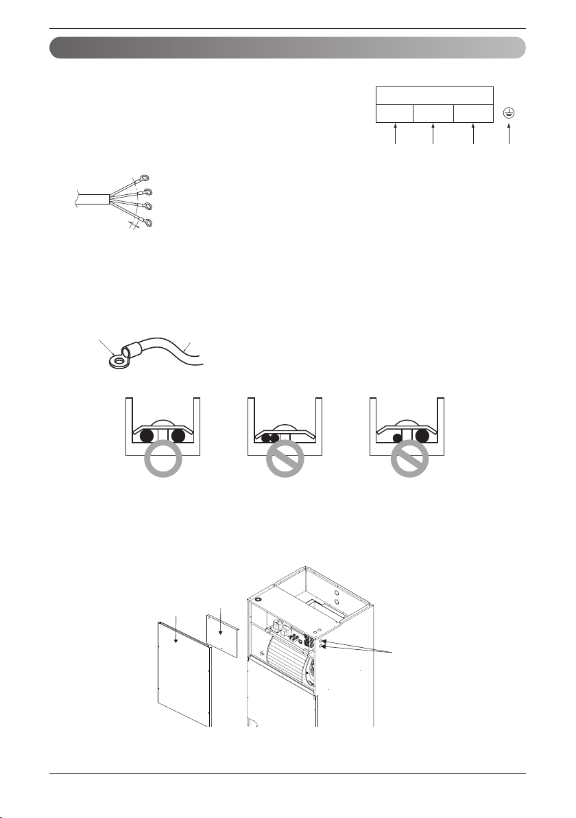
22 Vertical Air Handling Unit
Installation
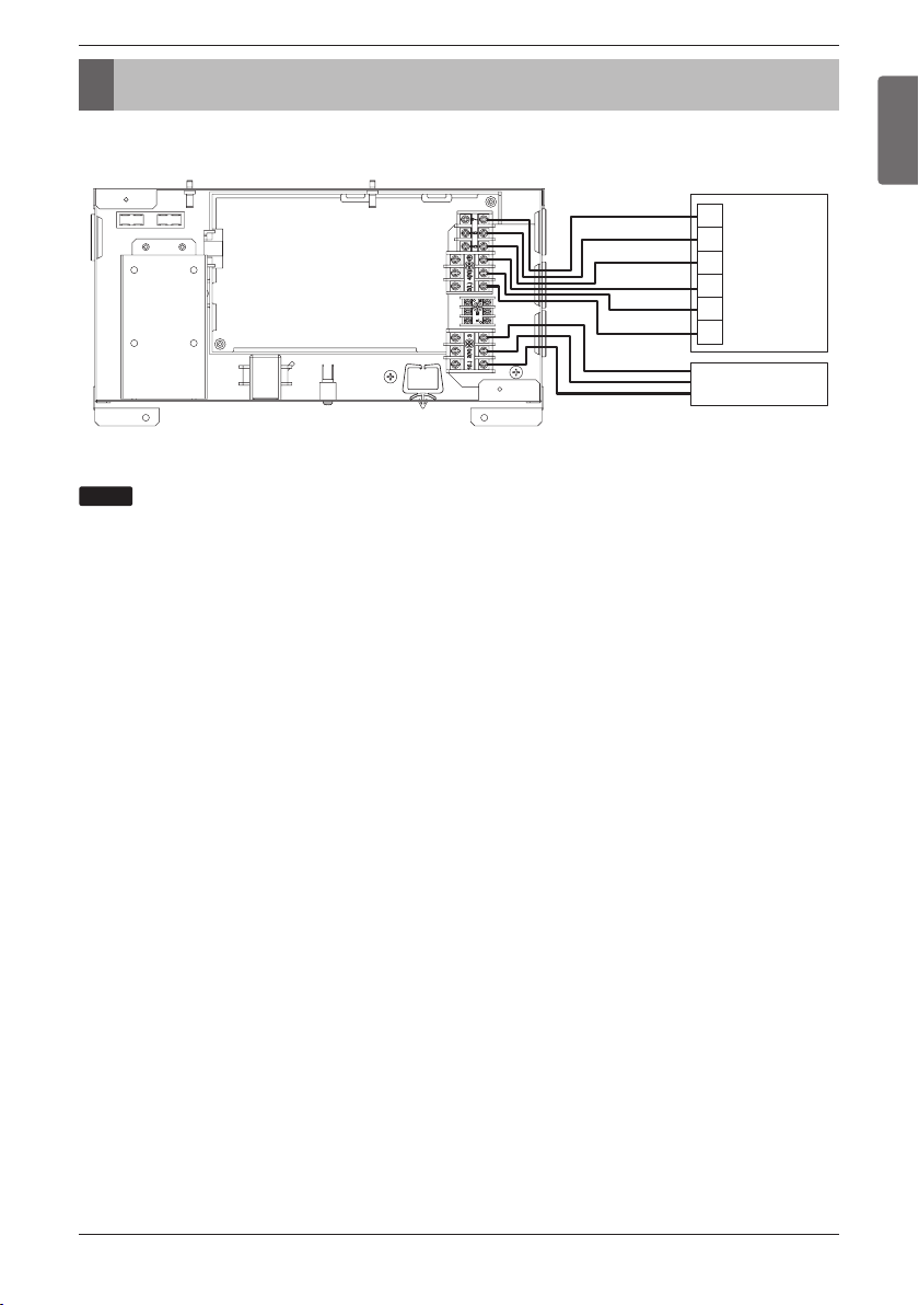
Connect the wires to the terminals on the control board individually
according to the outdoor unit connection.
Ensure that the color of the wires of outdoor unit and the terminal
No. are the same as those of indoor unit respectively.
208/230 V 1Φ 60 Hz
Terminal Block Indoor
1(L1) 2(L2) 3
Connected to outdoor unit or BD unit
Wiring
knockouts
Control
Box Cover
Upper
Front Panel
Wiring Connection
1. Detach the upper panel & control box cover. And remove two wiring Knockouts.
GN/YL
20 mm
(25/32 inch)
n Connecting cable
n Precautions when laying power and ground wiring
The power connecting cable between the outdoor and indoor units must
comply with the following specifications: NRTL Recognized (for example, UL
or ETL recognized and CSA certified).
AWG 18 (0.75 mm
2
)-4 is the minimum recommended wire size,
however, the selected conductors must comply with local codes and be
suitable for installation in wet locations.
Use round pressure terminals for connections to the power terminal block.
When none are available, follow the instructions below.
- Do not connect wiring of different thicknesses to the power
terminal block. (Slack in the power wiring may cause abnormal
heat.)
- When connecting wiring which is the same thickness, do as
shown in the figure below.
- For wiring, use the designated power wire and connect firmly, then secure to prevent outside pressure
being exerted on the terminal block.
- Use an appropriate screwdriver for tightening the terinal screws. A screwdriver with a small head will
strip the head and make proper tighterning impossible.
- Over-tightening the terminal screws may break them.
Round pressure terminal
Power wire
(Ground wire)

Installation Manual 23
ENGLISH
Installation
Thermostat cable
Wired remote
controller cable
Lock nut
Conduit
mounting plate
1/2 inch(21.3 mm)
Conduit
Connecting cable
2. Install conduit to the wiring knockouts.
Connect connecting / wired remote controller cable or Thermostat cable to terminal block through
the wiring knockouts.
:
1. Use connection cable NRTL(UL, ETL, CAS…) listed and stranded copper(4) THHN conductors,
sunlight (UV) resistant ROHS compliant PVC jacket 600 V direct burial listed, approved for wet
conditions. Temperature rated for -20 ℃(-4 ℉) to 90 ℃(194 ℉). And this cable should be enclosed
in conduit.
WARNING
• Be sure to comply with local and national codes while running the wire from the indoor unit to the outdoor
unit(size of wire and wiring method, etc).
• Every wire must be connected firmly.
• No wire should be allowed to touch refrigerant tubing, the compressor or any moving parts.
• The communication wirings of air conditioner should be separate and isolated from external
device’s electric wiring such as computers, elevator, radio & Television broadcasting facilities, as
well as medical imaging offices.
HAND OVER
Teach the customer the operation and maintenance procedures, using the operation manual.
(air filter cleaning, temperature control, etc.)
NOTE : Openings where field wiring enters the cabinet must be completely sealed.
NOTICE
!
24 Vertical Air Handling Unit
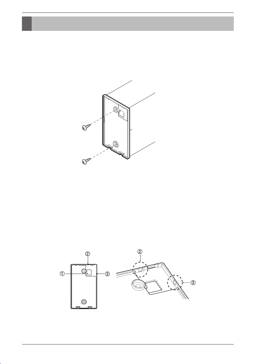
Remote controller installation
Remote controller installation
※Remote controller is provided as an accessory.
Please fix tightly using provided screw after placing remote controller setup
board on the place where you like to setup.
- Please set it up not to bend because poor setup could take place if setup board bends.
Please set up remote controller board fit to the reclamation box if there is a reclamation box.
Can set up Wired remote controller cable into three directions.
- Setup direction: the surface of wall reclamation, upper, right
- If setting up remote controller cable into upper and right side, please set up after removing remote
controller cable guide groove.
* Remove guide groove with long nose.
① Reclamation to the surface of the wall
② Upper part guide groove
③ Right part guide groove
<Wire guide grooves>
Installation Manual 25
ENGLISH
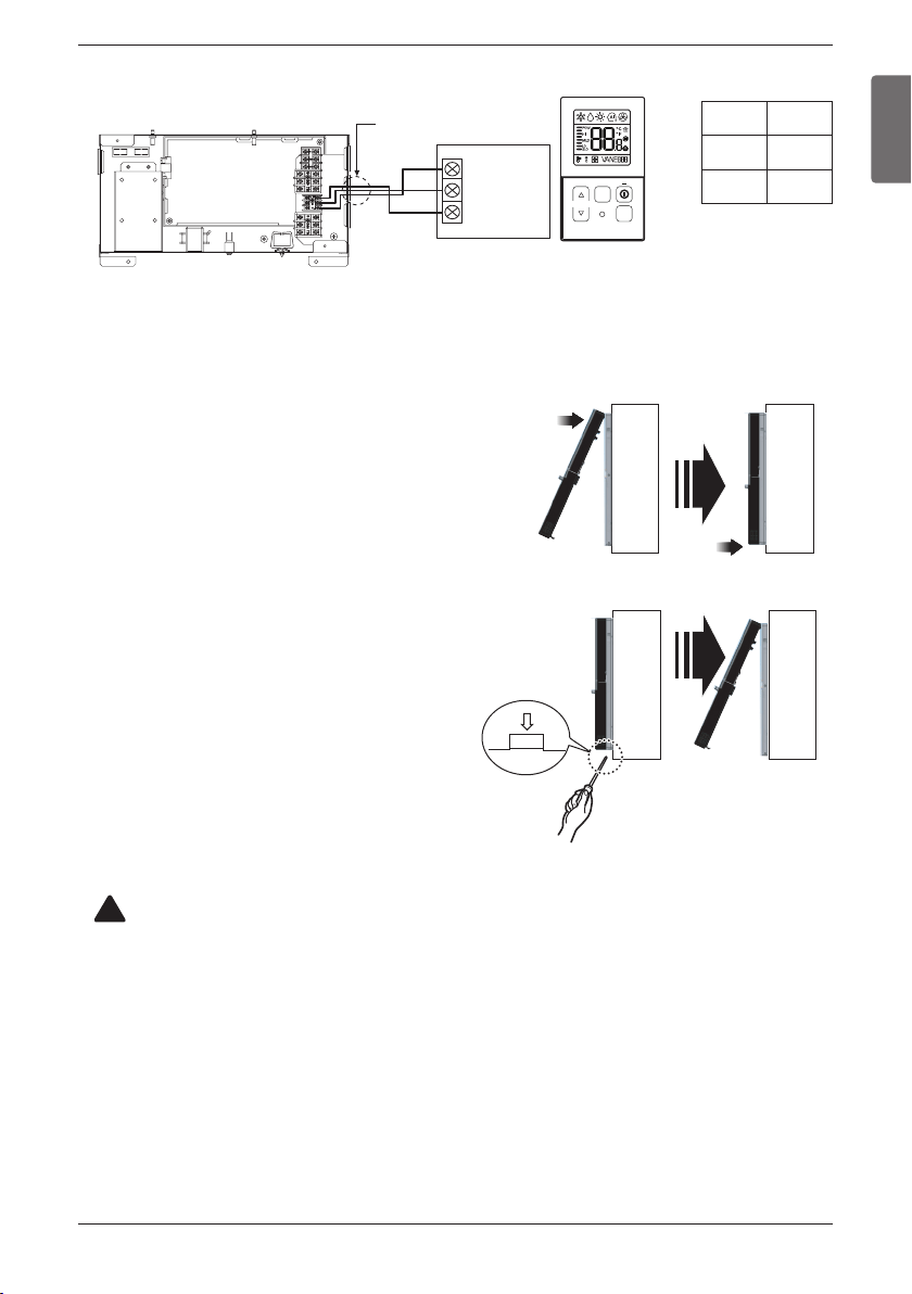
Remote controller installation
Please connect indoor unit and remote controller using connection cable.
Please use extension cable if the distance between wired remote controller
and indoor unit is more than 10 m(32-4/5 ft).
Wall
Side
Wall
Side
Wall
Side
Wall
Side
<Connecting order>
<Separating order>
TEMP
FAN
SPEED
OPER
MODE
Remote
Controller
PCB
YELLOW RED
BLACK
Signal
12v
GND
Indoor Unit Side
Connecting Cable
12 V Red
Signal Yellow
GND Black
CAUTION
When installing the wired remote controller, do not bury it in the wall.
(It can cause damage in the temperature sensor.)
Do not install the cable to be 50 m or above.
(It can cause communication error.)
• When installing the extension cable, check the connecting direction of the connector of
the remote controller side and the product side for correct installation.
• If you install the extension cable in the opposite direction, the connector will not be
connected.
• Specification of extension cable: 2547 1007 22# 2 core 3 shield 5 or above.
• Apply totally enclosed noncombustible conduit in case of local building code Requiring
plenum cable usage.
!
Please fix remote controller upper part
into the setup board attached to the
surface of the wall, as the picture below,
and then, connect with setup board by
pressing lower part.
- Please connect not to make a gap at the remote
controller and setup board’s upper and lower, right
and left part.
When separating remote controller from
setup board, as the picture below, after
inserting into the lower separating hole
using screw driver and then, spinning
clockwise, remote controller is
separated.
- There are two separating holes. Please individually
separate one at a time.
- Please be careful not to damage the inside
components when separating.
26 Vertical Air Handling Unit
Remote controller installation
Wired remote controller installation
Since the room temperature sensor is in the remote controller, the remote controller box should be
installed in a place away from direct sunlight, high humidity and direct supply of cold air to maintain
proper space temperature. Install the remote controller about 5 ft(1.5 m) above the floor in an area with
good air circulation at an average temperature.
Do not install the remote controller where it can be affected by:
- Drafts, or dead spots behind doors and in corners.
- Hot or cold air from ducts.
- Radiant heat from sun or appliances.
- Concealed pipes and chimneys.
- Uncontrolled areas such as an outside wall behind the remote controller.
- This remote controller is equipped with LCD. display. For proper display of the remote controller
LCD's, the remote controller should be installed properly as shown in Fig.1.
(The standard height is 4~5 ft (1.2~1.5 m) from floor level.)
TEMP
FAN
SPEED
OPER
MODE
TEMP
FAN
SPEED
OPER
MODE
TEMP
FAN
SPEED
OPER
MODE
5 feet
(1.5 meters)
no
no
yes
TEMP
FAN
SPEED
OPER
MODE
no
no
no
[Fig.1]
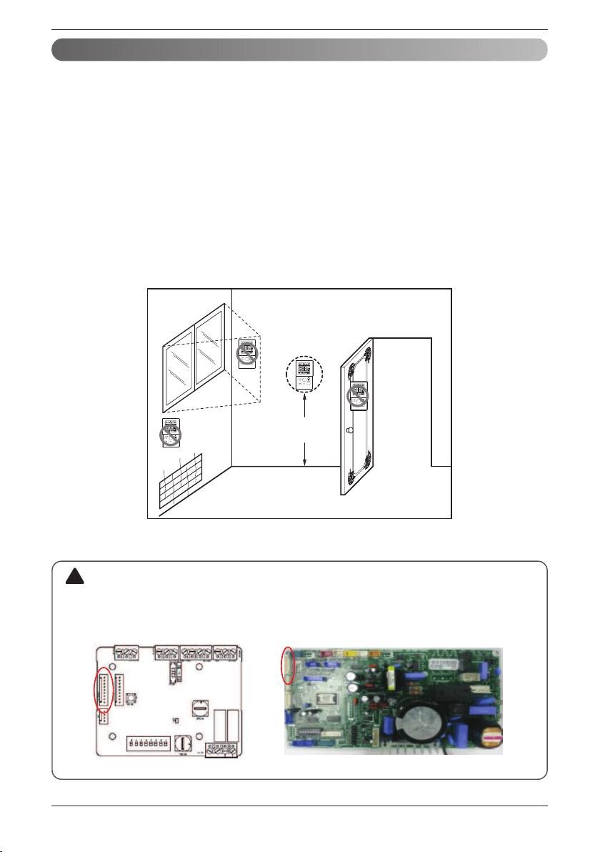
• When using the wired remote controller or central controller provided by LG, should disconnect
the wire connector between Indoor unit PCB(CN_CC) and dry contact PCB(CN_INDOOR).
CN_INDOOR
CN_CC
CAUTION
!
Installation Manual 27
3rd Party Thermostat
ENGLISH
3rd Party Thermostat
Thermostat
W2
Y
W
G
R
C
ODU
Indoor Unit Side
Can not use LG wired remote control and 3rd party thermostat at the same time.
When connecting the thermostat, please refer to the thermostat manual.
NOTE
28 Vertical Air Handling Unit
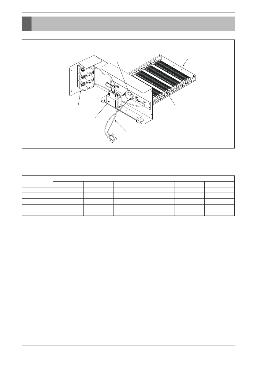
Internal Electric Heater(Accessory)
Terminal Block
Heater Cable
Relay
Heater Coil
Bracket
Bi metal
※ If you want to know more optional operation, please refer to the Internal Electric Heater Manual.
※ Heater Model
3 kW : ANEH033B1
5 kW : ANEH053B1
8 kW : ANEH083B2
10 kW : ANEH103B2
15 kW : ANEH153B2
20 kW : ANEH203B2
* Note: Image shown above may vary depends on model capacity.
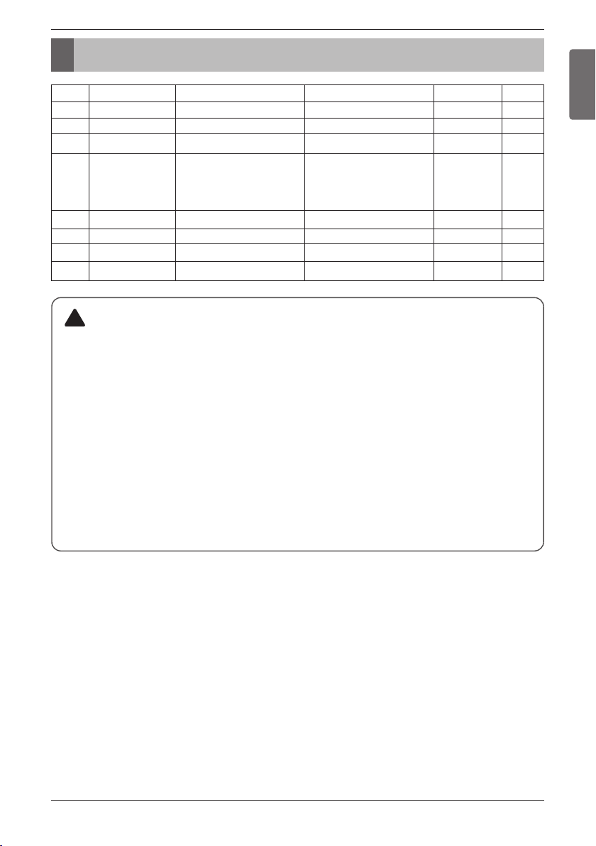
Available heater in model
Feature (Example: 5 kW)
Internal Electric Heater(Accessory)
Capacity
(kBtu/h (RT))
Heater Capacity (kW)
35810
15 20
18(1.5)
○○○○
Not available Not available
24(2.0)
○○○○
Not available Not available
36(3.0)
○○○○
Not available Not available
42(3.5)
○○○○
○ ○
48(4.0)
○○○○
○ ○
Installation Manual 29
DIP Switch Setting of Indoor unit PCB
ENGLISH
CAUTION
1. Indoor unit without Internal Electric Heater
- DIP switch 1, 2, 6, 8 must be set OFF.
2. In the case of indoor unit with Internal Electric heater, DIP switch 6 must be set ON.
- SW6 ON: Automatic Heater operation (Heater operates automatically according to the
heater logic without owner’s intervene.)
- SW6 OFF: Heater manual operation (Owner’s involvement is required for on/off operation.
But the heater operation would be as per the heater logic.)
3. In the case of indoor unit with Internal Electric heater, DIP switch 5 on if you want.
- SW5 ON: Fan operates continuously. (During defrosting or oil return operation,
uninterrupted heating can be attained, as a result of continuous heater and fan operation.
※During defrosting or oil return operation tepid air can come out.
- SW5 OFF: Fan discontinuous operation (There would be reduction in heating capacity
while defrosting or oil return operation.)
!
Function Description Setting Off Setting On Default
SW1
SW2
SW3
SW4
SW5
SW6
SW7
SW8
Communication
Cycle
Group Control
Dry Contact Mode
Installation
Heater linkage
Etc.
Etc.
N/A (Default)
N/A (Default)
Selection of Master or Slave
Selection of Dry Contact
Mode
Fan continuous operation
Selection of Heating Working
Spare
Spare
-
-
Master
Wired/Wireless remote
controller
Selection of Manual or Auto
operation Mode
Continuous operation Removall
-
-
-
-
-
Slave
Auto
-
-
-
-
Off
Off
Off
Off
Off
Off
Off
Off
DIP Switch Setting of Indoor unit PCB
30 Vertical Air Handling Unit
Product Data
Product Data
(Unit : CFM)
Minimum airflow by heater capacity
(Unit : CFM)
CAUTION
Do not use less than minimum airflow.
There is risk of fire or damage to the product.
!
Capacity
(kBtu/h (RT))
Heater Capacity (kW)
35810
15 20
18(1.5) 480 480 480 480 Not available Not available
24(2.0) 480 480 480 480 Not available Not available
36(3.0) 800 800 800 800 Not available Not available
42(3.5) 1 000 1 000 1 000 1 000 1 000 1 000
48(4.0) 1 000 1 000 1 000 1 000 1 000 1 000

US
Please call the installing contractor of your product, as warranty service will be
provided by them.
CANADA
Service call Number # : (888) LG Canada, (888) 542-2623
Numéro pour les appels de service : LG Canada, 1-888-542-2623