Loading ...
Loading ...
Loading ...
WARNING – SERVICING TO BE CARRIED OUT ONLY BY AN AUTHORISED PERSON
Disconnect from electricity before servicing. Check appliance is safe when you have nished.
42
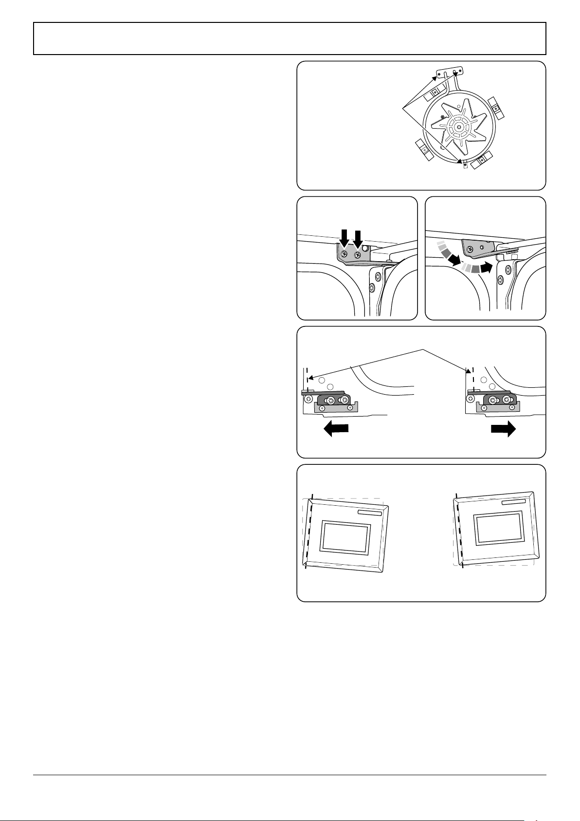
5.5 To Remove an Oven Element
n
DISCONNECT FROM THE ELECTRICITY SUPPLY.
Remove the oven inner back (see 5.2).
Remove the 2 screws from the top of the element and the 1
from the bottom of the element (Fig. 12.5).
Carefully lift the element out, disconnecting the terminals
connected to the element (noting their positions).
If it is not possible to disconnect the leads in this way, pull the
cooker forward to gain access to the rear, remove the screws
securing the electric cover to the back sheet, remove the
cover and disconnect the terminals from the rear.
Fit the new element and reassemble in reverse order. Check
the operation of the oven.
6. Doors
6.1 To Remove the Grill Door
Remove the left-hand side panel (see 1.2). Remove the plinth
(4 screws) and the central vertical cover (5screws). Remove
the 2 countersunk screws (1 each side) securing the grill
hinge arms to the front of the grill chamber.
Note: The arms are spring tensioned. Carefully remove the
grill door. Retain the gaskets.
Reassemble in reverse order, making sure that the gasket
is tted between the hinge arm and the front of the grill
chamber.
6.2 To Replace an Oven Door
Open the oven door. Support the door and loosen the 2
screws securing the upper hinge and gasket to the cooker
front (Fig. 12.6).
n
THE DOOR IS HEAVY, SO TAKE CARE.
Support the door and remove the screw nearest the hinge
pin (Fig. 12.7). Swing the hinge up and away from the door
hinge pin. Lift the door away from the lower hinge and
remove. Reassemble in reverse order.
6.3 To Adjust an Oven Door Angle
The bottom hinge of either oven door can be adjusted to
alter the angle of the door (Fig. 12.8). Loosen the bottom
hinge xing screws and use the notch and a at bladed
screwdriver to move the position of the hinge to set the
hinge position (Fig. 12.9).
Retighten the hinge screws.
ArtNo.320-0001 Door hinges
1
ArtNo.320-0001 Door hinges
2
Element xing screws
ArtNo.321-0005 Fan oven element
Fig. 12.5
Fig. 12.6 Fig. 12.7
ArtNo.320-0006 Oven door hinge adjustment 1
ArtNo.320-0007 Oven door hinge adjustment 2
Centreline of hinge pin
Oven door omitted for clarity
Fig. 12.8
Fig. 12.9
Loading ...
Loading ...
Loading ...