Loading ...
Loading ...
Loading ...
www.factorybuysdirect.com
7200254-01A
INSTALLATION
CHECK GAS TYPE
Use only natural gas. If your gas supply is not natural gas, you must install On/Off Safety Pilot
Valve Kit (see Accessories, page 19).
If the replace does not have a gas supply shutoff valve, one must be installed.
The replace chimney ue and vent must be
drafting properly. To check the vent for proper
drafting, light a tightly rolled newspaper on
one end and place it at the inside front edge of
the replace. Observe the smoke and be sure
the vent is properly drawing it up the chimney.
If the smoke spills out into the room, extin-
guish the ame and remove any obstruction
until proper venting is achieved. The chimney
ue must remain open a minimum of 3" at all
times during the operation of this appliance.
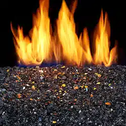
INSTALLING DAMPER CLAMP
Secure the damper stop clamp provided to
the leading edge of the damper as shown in
Figure 2. If for any reason this clamp doesn't
work on your replace, another suitable clamp
or permanent stop must be installed, or the
damper blade must be cut or removed.
VENTING SPECIFICATIONS FOR INSTALLATION
Figure 2 - Attaching Damper Clamp
Masonry Fireplace
Manufactured
Fireplace
Damper
Damper
Damper
Damper
Clamp
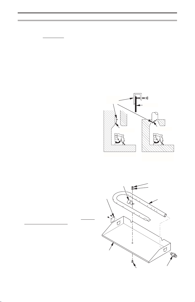
HEARTH KIT ASSEMBLY
Note: The following instructions apply to
dual ame "U" style burners. Be sure all pipe
threaded connections are tight, and have
thread compound to prevent leaks.
1. Determine which side the gas line will be
coming into the replace.
Gas line is on the right side. This unit
is manufactured with the gas inlet on the
right side of the burner pan. See Installa-
tion and Gas Connection, page 8.
Gas line is on the left side. If your gas
line will be coming into the replace from
the left side, continue with step 2.
2. Using a screwdriver, remove cover plate
on left side of burner pan (see Figure 3).
3. Unscrew burner inlet tting from burner
manifold (see Figure 3).
4. Place burner manifold in pan with thread-
ed opening facing opening on left side.
Burner Pan
Assembly (Facing
Front of Fireplace)
Figure 3 - Installing Burner
Nut
Washer
Burner
Manifold
Burner
Clamp
Cover
Plate
Burner Inlet
Fitting
Screw
Loading ...
Loading ...
Loading ...