Loading ...
Loading ...
Loading ...
Rinnai 16 HW_GI_FM10 OIM
TESTING
1. Before nal connection of the water heater purge
gas, hot water and cold water supply lines. Swarf in
either the gas or water supplies may cause damage or
malfunction which is not covered by warranty.
2. See Table 1 for connection size, water and gas
pressure specications.
3. Turn on gas and cold water supplies.
4. Test for water leaks and gas escapes.
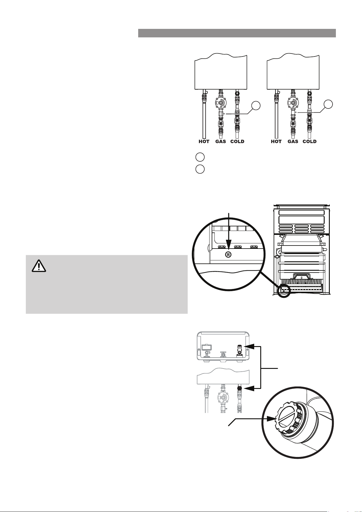
5. Isolate gas and water supplies. Remove test point
screw located on the regulator inlet pressure test point
and attach pressure gauge Fig. 1.
6. Turn on gas and open hot water taps fully. Ensure
water ow lever is in the maximum ow position. Refer
to "Water Flow and Temperature Adjustment" on page
8.
7. With all gas appliances in operation at maximum gas
rate, the pressure at the regulator inlet pressure test
point should read between 1.13 - 3.0 kPa on Natural
Gas. On LPG the pressure should be 2.75 - 3.0 kPa.
If the pressure is lower, the gas supply is inadequate
and the appliance will not operate to specication. It
is the Installers responsibility to check the gas meter,
service regulator and pipe work for correct operation/
sizing and rectify as required.
NOTE
If the sparker activates but the pilot and main
burner do not light, then the gas pressure at
the outlet of the regulator is too low.
Increase the pressure at the outlet of the
regulator by slowly turning the adjustment
screw clockwise until a suitable pilot ame
and main burner ame are established.
8. Replace the test point screw on the regulator inlet
pressure test point.
9. Isolate gas and water supplies. Remove the test point
screw located to the burner pressure test point on the
left hand side of burner manifold as shown right and
attach pressure gauge Fig. 2
10. Turn on the gas and open hot water taps fully. Ensure
the water ow lever is in the maximum ow position.
11. For burner test point pressures refer to the appliance
data plate. If the pressures are dierent adjust the inlet
gas regulator to achieve the required burner test point
pressures.
12. Close all hot water taps including the shower.
13. Inspect and clean the strainer located on the cold
water inlet connection. This procedure may need
to be repeated to ensure the strainer remains clear,
especially on new installations Fig. 3.
14. After testing is completed, explain to the householder
the functions and operation of the water heater.
Test Point Screw
Fig. 2.
Cold Inlet
Connection/
Strainer
Location
Strainer Cap
Fig. 3.
Fig. 1.
Propane
Gas
1
Natural
Gas
2
1 Propane gas regulator inlet pressure test point screw
2 Natural gas regulator inlet pressure test point screw
COMMISSIONING
Loading ...
Loading ...
Loading ...