Loading ...
Loading ...
Loading ...
Assembly
Stand Assembmy
Carefully unpack the stand parts (see below) from the
packaging.
ToomsNeeded:
, #2 phillips head screw driver
Adjustable Wrench
, Level
Parts
A EndFrame.......................................................................................................2
B LongSupport Rail.......................................................................................4
C RearLevelingLegs(attachedto endframes]..............................2
D Shelves..............................................................................................................2
E Pan-HeadSc{ews.....................................................................................24
F LeftSidePanel(with hinge holes].....................................................1
G RightSidePanel(witI_no hinge holes]...........................................1
H BackPanel......................................................................................................1
I Door....................................................................................................................1
J Hinges(attachedto the dooO..............................................................2
K FrontFoot.........................................................................................................2
L M5 x 16Hex-PhillipsHeadCap Screw- _" (16mini long....6
M FrontFootLevelingHead........................................................................2
N FiatHeadScrews.........................................................................................6
FF M5 x 20 Hex-PhillipsHeadCap Screw- 3/4"(20ram]long__2
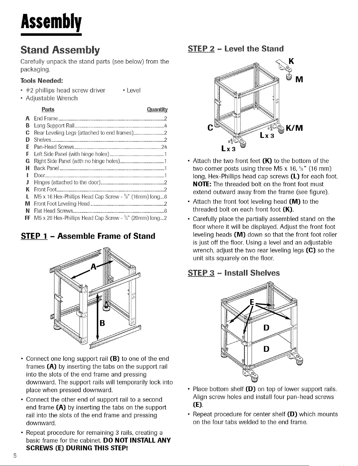
STEP 1 - Assemble Frame of Stand
B
• Connect one long support rail (:B) to one of the end
frames I:A) by inserting the tabs on the support rail
into the slots of the end frame and pressing
downward. The support rails will temporarily lock into
place when pressed downward.
• Connect the other end of support rail to a second
end frame I:A) by inserting the tabs on the support
rail into the slots of the end frame and pressing
downward.
• Repeat procedure for remaining 3 rails, creating a
basic frame for the cabinet. DO NOT INSTALL ANY
SCREWS I:E) DURING THIS STEP!
STEP 2 - Level the Stand
@M
C WM
g
Lx3
Lx3
• Attach the two front feet (K) to the bottom of the
two corner posts using three M5 x 16, 5/8"(16 ram]
long, Hex-Phillips head cap screws I:L) for each foot.
NOTE: The threaded bolt on the front foot must
extend outward away from the frame (see figure).
• Attach the front foot leveling head I:M) to the
threaded bolt on each front foot I:K).
• Carefully place the partially assembled stand on the
floor where it will be displayed. Adjust the front foot
leveling heads I:M) down so that the front foot roller
is just off the floor. Using a level and an adjustable
wrench, adjust the two rear leveling legs I:C) so the
unit sits squarely on the floor.
STEP 3 - Install Shelves
D
D
• Place bottom shelf (D) on top of lower support rails.
Align screw holes and install four pan-head screws
(E).
• Repeat procedure for center shelf I:D) which mounts
on the four tabs welded to the end frame.
Loading ...
Loading ...
Loading ...