
Loading ...
Loading ...
Loading ...
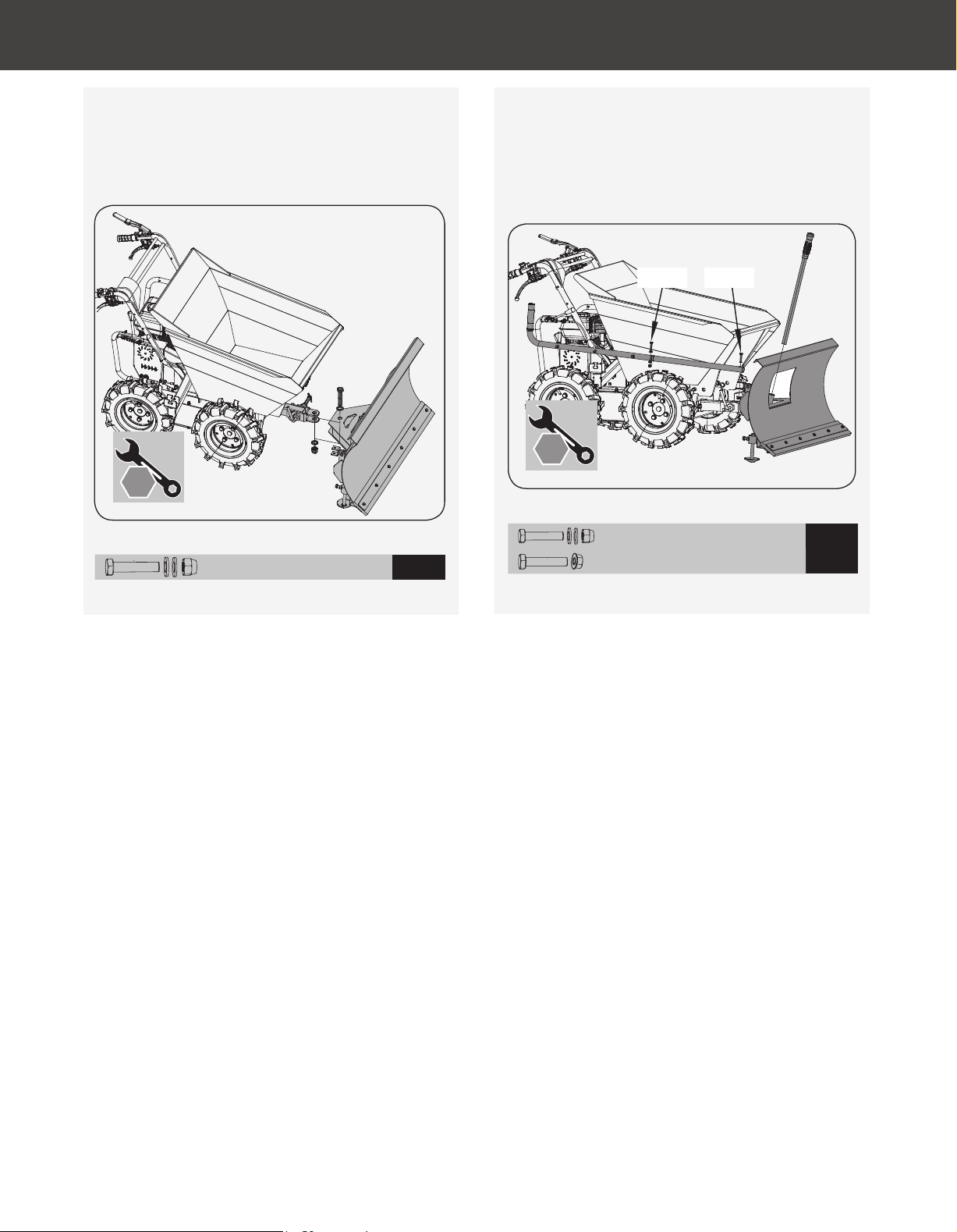
Figure 6c
Figure 6d
5.
M8 × 40 × 1
7
M8 × 50 × 1
M20 × 100 × 1
6
4.
10
mm
13
mm
18
mm
19
mm
12
mm
7
mm
30
mm
8
mm
M8x50M8x40
10
mm
13
mm
18
mm
19
mm
12
mm
7
mm
30
mm
8
mm
X 2
X 2
Fix the blade assembly to the flange bracket with
M20×100 bolt, washer and nut. Do not overtighten,
allowing the blade to rotate freely in both directions.
(See
Figure 6c
)
Connect the angle control lever and extension by
M8×40 bolt, washer and nut. Attach the extension to
the blade with M8×50 bolt and nut. Lock the second
pin of the angle control lever into the limit slot of the
bracket. (See
Figure 6d
)
12
Power Wheelbarrow
»
Operator’s Manual
YD4103PM03 - 1807
Assembly
|
Loading ...
Loading ...
Loading ...