

Operator's Manual
ZT 71
Zero-Turn Rear Engine Riders with Electric Start
Model No.
107.27772 (20HP Kohler with 44" Mower)
107.27774 (22HP Briggs & Stratton with 50" Mower)
CAUTION: Before using this product, read
the manual and follow all its Safety Rules
and Operating Instructions.
For answers to your questions about this
product, call:
1=800=659=5917
Sears Craftsman Help Line
5 am - 5 pro, Mon - Sat
Nota: Una traducci6n en espa6ol de este Manual
del Operador puede encontrarse en la p&gina 35.
Sears, Roebuck and Co., Hoffman Estates, IL 60179 U.S.A.
Visit our Craftsman website: www.sears.com/craftsman
TP 199-4163-06-CZ-C
1727941
Revision 06
Nora: Una traducci6n en espa6ol de este Manual del Operador puede encontrarse en la p;&gina 35.
Warranty Statement ..................................................... 2
Safety Rules & Information ......................................... 3
Identification Numbers ................................................ 7
Optional Accessories .................................................. 8
Literature Package Contents ...................................... 8
Pre-Operation ............................................................... 9
Operation .................................................................... 10
Maintenance ............................................................... 17
Service & Adjustments ............................................. 28
Storage ....................................................................... 32
Troubleshooting ......................................................... 33
Spanish Operator's Manual ...................................... 35
Repair Parts ......................................................... PTS-f
Hardware & Torque Specifications ................... PTS-39
Repair Protection Agreement ........ inside Back Cover
Service Numbers ........................................ Back Cover
NOTE: In this manual, "left" and "right" are referred to as seen from the operating position.
LIMITED WARRANTY ON CRAFTSMAN RIDING EQUIPMENT
For two (2) years from the date of purchase, if this Craftsman riding equipment is maintained, lubricated and tuned up
according to the instructions in the owner's manual, Sears will repair or replace free of charge any parts that are
found to be defective in material or workmanship according to the guidelines of coverage listed below. Sears will also
provide free labor for these applicable warrantied parts for the two full years. During the first 30 days of purchase,
there will be no charges to service the product at your home for issues covered by this warranty. (See exclusions
below). For your convenience, iN HOME warranty service will still be available after the first 30 days of purchase, but
a trip charge will apply. This charge will be waived if the Craftsman product is dropped off at an authorized Sears loca-
tion. For the nearest authorized Sears location, please call 1-800-MY-HOME. This warranty applies only while this
product is within the United States.
THIS WARRANTY DOES NOT COVER:
Expendable items which become worn during normal
use, including but not limited to blades, spark plugs,
air cleaners, belts, and oil filters.
Standard maintenance servicing, oil changes, or
tune-ups.
Tire replacement or repair caused by punctures from
outside objects, such as nails, thorns, stumps, or
glass.
Repairs necessary because of operator abuse,
including but not limited to, damage caused by towing
objects beyond the capability of the riding equipment,
impacting objects that bend the frame or crankshaft,
or over-speeding the engine.
LIMITED WARRANTY ON BATTERY
Repairs necessary because of operator negligence,
including but not limited to, electrical and mechanical
damage caused by improper storage, failure to use
the proper grade and amount of engine oil, failure to
keep the deck clear of flammable debris, or failure to
maintain the equipment according to the instructions
contained in the owner's manual.
Engine (fuel system) cleaning or repairs caused by
fuel determined to be contaminated or oxidized
(stale). In general, fuel should be used within 30 days
of its purchase date.
Normal deterioration and wear of the exterior of the
exterior finishes, or product label replacement.
• Riding equipment used for commercial or rental pur-
poses.
For ninety (90) days from date of purchase, if any battery included with this riding equipment proves defective in
material or workmanship and our testing determines the battery will not hold a charge, Sears will replace the battery
at no charge. During the first 30 days of purchase, there will be no charges to replace the battery at your HOME. After
first 30 days, for your convenience, IN-HOME warranty service will still be available but a trip charge will apply. This
charge will be waived if the Craftsman product is dropped off at an authorized Sears location. FOR THE NEAREST
AUTHORIZED LOCATION, PLEASE CALL 1-800-4-MY-HOME. This battery warranty applies only while this product
is within the United States.
This warranty gives you specific legal rights, and you may also have other rights which vary from state to state.
Sears, Roebuck and Co., Dept. 817WA, Hoffman Estates, IL 60179
Readthesesafetyrulesandfollowthemclosely.Failuretoobeytheserulescouldresultin lossofcontrol
of unit,severepersonalinjuryordeathtoyou,or bystanders,ordamagetopropertyorequipment.
This mowing deck is capable of amputating hands and feet and throwingobjects,
]'he triangle _ in text signifies important cautions or warnings which must be followed.
GENERAL OPERATION
1. Read, understand, and follow all instructions in the
manual and on the unit before starting.
2. Do not put hands or feet near rotating parts or under
the machine. Keep clear of the discharge opening at
all times.
3. Only allow responsible adults, who are familiar with
the instructions, to operate the unit (local regulations
can restrict operator age).
4. Clear the area of objects such as rocks, toys, wire,
etc., which could be picked up and thrown by the
blade(s).
5. Be sure the area is clear of other people before mow-
ing. Stop the unit if anyone enters the area.
6. Never carry passengers.
7. Do not mow in reverse unless absolutely necessary.
Always look down and behind before and while travel-
ling in reverse.
8. Never direct discharge material toward anyone. Avoid
discharging material against a wall or obstruction.
Material may ricochet back toward the operator. Stop
the blade(s) when crossing gravel surfaces.
9. Do not operate the machine without the entire grass
catcher, discharge guard (deflector), or other safety
devices in place and operational.
10. Slow down before turning.
11. Never leave a running unit unattended. Always disen-
gage the blades (PTO), set parking brake, stop
engine, and remove keys before dismounting.
12. Disengage blades (PTO) when not mowing. Shut off
engine and wait for all parts to come to a complete
stop before cleaning the machine, removing the grass
catcher, or unclogging the discharge guard.
13. Operate the machine only in daylight or good artificial
light.
14. Do not operate the unit while under the influence of
alcohol or drugs.
15 Watch for traffic when operating near or crossing
roadways.
16. Use extra care when loading or unloading the unit
into a trailer or truck.
17. Always wear eye protection when operating this unit.
18. Data indicates that operators, age 60 years and
above, are involved in a large percentage of power
equipment-related injuries. These operators should
evaluate their ability to operate the equipment safely
enough to protect themselves and others from injury.
19. Follow the manufacturer's recommendations for wheel
weights or counterweights.
20. Keep in mind the operator is responsible for accidents
occurring to other people or property.
21 .All drivers should seek and obtain professional and
practical instruction.
22. Always wear substantial footwear and trousers.
Never operate when barefoot or wearing sandals.
23. Before using, always visually check that the blades
and blade hardware are present, intact, and secure.
Replace worn or damaged parts.
24. Disengage attachments before: refueling, removing
an attachment, making adjustments (unless the
adjustment can be made from the operator's posi-
tion).
26. Before leaving the operator's position for any reason,
engage the parking brake (if equipped), disengage
the blades (PTO), stop the engine, and remove the
key.
27.T0 reduce fire hazard, keep the unit free of grass,
leaves, & excess oil. Do not stop or park over dry
leaves, grass, or combustible materials.
28. It is a violation of California Public Resource Code
Section 4442 to use or operate the engine on or near
any forest-covered, brush-covered, or grass-covered
land unless the exhaust system is equipped with a
spark arrester meeting any applicable local or state
laws. Other states or federal areas may have similar
laws.
TRANSPORTING AND STORAGE
1. When transporting the unit on an open trailer, make
sure it is facing forward, in the direction of travel. If
the unit is facing backwards, wind lift could damage
the unit.
2. Always observe safe refueling and fuel handling prac-
tices when refueling the unit after transportation or
storage.
3. Never store the unit (with fuel) in an enclosed poorly
ventilated structure. Fuel vapors can travel to an igni-
tion source (such as a furnace, water heater, etc.)
and cause an explosion. Fuel vapor is also toxic to
humans and animals.
TP 600-4103-00-ZT-UV
4. Always follow the engine manual instructions for
storage preparations before storing the unit for both
short and long term periods.
5. Always follow the engine manual instructions for
proper start-up procedures when returning the unit to
service.
6. Never store the unit or fuel container inside where
there is an open flame or pilot light, such as in a
water heater. Allow unit to cool before storing.
3
SLOPE OPERATION
Slopes are a major factor related to loss-of-control and tip-
over accidents, which can result in severe injury or death.
Operation on all slopes requires extra caution. If you cannot
back up the slope or if you feel uneasy on it, do not operate
on it.
Control of a walk-behind or ride-on machine sliding on a
slope will not be regained by the application of the brake.
The main reasons for loss of control are: insufficient tire
grip on the ground, speed too fast, inadequate braking, the
type of machine is unsuitable for its task, lack of awareness
of the ground conditions, incorrect hitching and load distri-
bution.
1. Mow across the face of slopes, not up and down.
2. Watch for holes, ruts, or bumps. Uneven terrain could
overturn the unit. Tall grass can hide obstacles.
3. Choose a slow speed so that you will not have to stop
or change speeds while on the slope.
4. Do not mow on wet grass. Tires may lose traction.
5. Never mow down slopes.
6. Avoid starting, stopping, or turning on a slope. If tires
lose traction (i.e. machine stops forward motion on a
slope), disengage the blade(s) (PTO) and drive slow-
ly off the slope.
7. Keep all movement on slopes slow and gradual. Do
not make sudden changes in speed or direction,
which could cause the machine to rollover.
8. Use extra care while operating machines with grass
catchers or other attachments; they can affect the
stability of the unit. Do not use on steeps slopes.
9. Do not try to stabilize the machine by putting your
foot on the ground (ride-on units).
10. Do not mow near drop-offs, ditches, or embank-
ments. The mower could suddenly turn over if a
wheel is over the edge of a cliff or ditch, or if an edge
caves in.
11. Do not use grass catchers on steep slopes.
12. Do not mow slopes if you cannot back up them.
13. See your authorized dealer/retailer for recommenda-
tions of wheel weights or counterweights to improve
stability.
14. Remove obstacles such as rocks, tree limbs, etc.
15. Use slow speed.Tires may lose traction on slopes
even through the brakes are functioning properly.
16. Do not turn on slopes unless necessary, and then,
turn slowly and gradually uphill, if possible. Never
mow down slopes.
TOWED EQUIPMENT (RIDE-ON UNITS)
1. Tow only with a machine that has a hitch designed for
towing. Do not attach towed equipment except at the
hitch point.
2. Follow the manufacturer's recommendations for
weight limit for towed equipment and towing on
slopes. See attaching a trailer under OPERATION.
3. Never allow children or others in or on towed equip-
ment.
4. On slopes, the weight of the towed equipment may
cause loss of traction and loss of control.
5. Travel slowly and allow extra distance to stop.
6. Do not shift to neutral and coast down hill.
WARNING
Never operate on slopes greater than 17.6 percent
(10 °) which is a rise of 3-1/2 feet (106 cm) vertically in
20 feet (607 cm) horizontally.
Select slow ground speed before driving onto slope.
Use extra caution when operating on slopes with rear-
mounted grass catchers.
Mow across the face of slopes, not up and down,use
caution when changing directions and DO NOT
START OR STOP ON SLOPE.
CHILDREN
Tragic accidents can occur if the operator is not alert to the
presence of children. Children are often attracted to the unit
and the mowing activity. Never assume that children will
remain where you last saw them.
1. Keep children out of the mowing area and under the
watchful care of another responsible adult.
2. Be alert and turn unit off if children enter the area.
3. Before and during reverse operation, look behind and
down for small children.
4. Never carry children, even with the blade(s) off. They
may fall off and be seriously injured or interfere with
safe unit operation. Children who have been given
rides in the past may suddenly appear in the mowing
area for another ride and be run over or backed over
by the machine.
5. Never allow children to operate the unit.
6. Use extra care when approaching blind corners,
shrubs, trees, or other objects that may obscure
vision.
EMISSIONS
1. Engine exhaust from this product contains chemicals
known, in certain quantities, to cause cancer, birth
defects, or other reproductive harm.
2. Look for the relevant Emissions Durability Period and
Air Index information on the engine emissions label.
iGNiTION SYSTEM
1. This spark ignition system complies with Canadian
ICES-002.
SERVICE AND MAINTENANCE
Safe Handling of Gasoline
1. Extinguish all cigarettes, cigars, pipes, and other
sources of ignition.
2. Use only approved gasoline containers.
3. Never remove the gas cap or add fuel with the engine
running. Allow the engine to cool before refueling.
4. Never fuel the machine indoors.
5. Never store the machine or fuel container where there
is an open flame, spark, or pilot light such as near a
water heater or other appliance.
6. Never fill containers inside a vehicle or on a truck bed
with a plastic bed liner. Always place containers on
the ground away from your vehicle before filling.
7. Remove gas-powered equipment from the truck or
trailer and refuel it on the ground. If this is not possi-
ble, then refuel such equipment on a trailer with a
portable container, rather than from a gasoline dis-
penser nozzle.
8. Keep nozzle in contact with the rim of the fuel tank or
container opening at all times until fueling is com-
plete. Do not use a nozzle lock-open device.
9. If fuel is spilled on clothing, change clothing immedi-
ately.
10. Never over-fill the fuel tank. Replace gas cap and
tighten securely.
11. Use extra care in handling gasoline and other fuels.
They are flammable and vapors are explosive.
12. If fuel is spilled, do not attempt to start the engine but
move the machine away from the area of spillage and
avoid creating any source of ignition until fuel vapors
have dissipated.
13. Replace all fuel tank caps and fuel container caps
securely.
Service & Maintenance
1. Never run the unit in an enclosed area where carbon
monoxide fumes may collect.
2. Keep nuts and bolts, especially blade attachment
bolts, tight and keep equipment in good condition.
3. Never tamper with safety devices. Check their proper
operation regularly and make necessary repairs if
they are not functioning properly.
4. Keep unit free of grass, leaves, or other debris build-
up. Clean up oil or fuel spillage, and remove any fuel-
soaked debris. Allow machine to cool before storage.
5. If you strike an object, stop and inspect the machine.
Repair, if necessary, before restarting.
6. Never make adjustments or repairs with the engine
running.
7. Check grass catcher components and the discharge
guard frequently and replace with manufacturer's rec-
ommended parts, when necessary.
8. Mower blades are sharp. Wrap the blade or wear
gloves, and use extra caution when servicing them.
9. Check brake operation frequently. Adjust and service
as required.
10. Maintain or replace safety and instructions labels, as
necessary.
11. Do not remove the fuel filter when the engine is hot
as spilled gasoline may ignite. Do not spread fuel line
clamps further than necessary. Ensure clamps grip
hoses firmly over the filter after installation.
12. Do not use gasoline containing METHANOL, gasohol
containing more than 10% ETHANOL, gasoline addi-
tives, or white gas because engine/fuel system dam-
age could result.
13. If the fuel tank must be drained, it should be drained
outdoors.
14. Replace faulty silencers/mufflers.
15. Maintain or replace safety and instruction labels as
necessary.
16. Use only factory authorized replacement parts when
making repairs.
17. Always comply with factory specifications on all set-
tings and adjustments.
18. Only authorized service locations should be utilized
for major service and repair requirements.
19. Never attempt to make major repairs on this unit
unless you have been properly trained. Improper
service procedures can result in hazardous operation,
equipment damage and voiding of manufacturer's
warranty.
20. On multiple blade mowers, take care as rotating one
blade can cause other blades to rotate.
21. Do not change engine governor settings or over-
speed the engine. Operating the engine at excessive
speed can increase the hazard of personal injury.
22. Disengage drive attachments, stop the engine,
remove the key, and disconnect the spark plug wire(s)
before: clearing attachment blockages and chutes,
performing service work, striking an object, or if the
unit vibrates abnormally. After striking an object,
inspect the machine for damage and make repairs
before restarting and operating the equipment.
23. Never place hands near moving parts, such as a
hydro pump cooling fan, when the tractor is running.
(Hydro pump cooling fans are typically located on top
of the transaxle).
25. WARNING: Stored energy device. Improper release
of springs can result in serious personal injury.
Springs should be removed by an authorized techni-
cian.
5

SAFETY & OPERATION DECALS
This unit has been designed and manufactured to pro-
vide you with the safety and reliability you would expect
from an industry leader in outdoor power equipment
manufacturing.
Although reading this manual and the safety instructions
it contains will provide you with the necessary basic
knowledge to operate this equipment safely and effec-
tively, we have placed several safety labels on the unit to
remind you of this important information while you are
operating your unit.
OPERATION
Decal = Operation, Upper
Part No. 1727855
All DANGER, WARNING, CAUTION and instructional
messages on your rider and mower should be carefully
read and obeyed. Personal bodily injury can result when
these instructions are not followed. The information is for
your safety and it is important! The safety decals below
are on your rider and mower.
If any of these decals are lost or damaged, replace them
at once. Contact a Sears Parts & Service Center for
replacements.
These labels are easily applied and will act as a constant
visual reminder to you, and others who may use the
equipment, to follow the safety instructions necessary for
safe, effective operation.
4f%
Decal - ignition
Switch
Part He. 1726526
Decal - Transmission
Release Valve
Part No. 1720543
Decal - Cutting
Height Adjustment
Part No, 1726642
Decal = Danger/Warning, Lower
Part No. 1727856
OTATINGCUTTINGBLADIJ
Do not operate iiiowet
wilheut deflector or enlire
ss _teher inplaee. ,,
Decal - Danger,
Rotating Blades
Part No. 1704277
Decal =Danger,
Rotating Blades
Part No. 1704276
For Part8 & Service
CRR MRN
\ www _ea s c°_
.......................JlllllHIlll
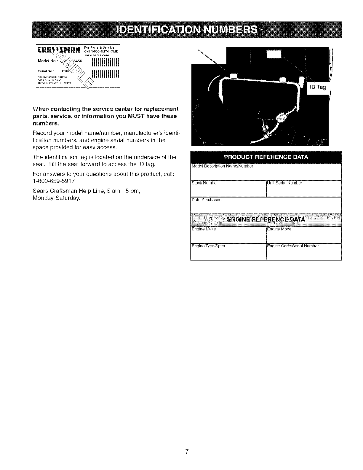
When contacting the service center for replacement
parts, service, or information you MUST have these
numbers,
Record your model name/number, manufacturer's identi-
fication numbers, and engine serial numbers in the
space provided for easy access.
The identification tag is located on the underside of the
seat. Tilt the seat forward to access the ID tag.
For answers to your questions about this product, call:
1-800-659-5917
Sears Craftsman Help Line, 5 am - 5 pm,
Monday-Saturday.
Model Description Name/Number
Stock Number Unit Serial Number
Date Purchased
Engine Make
Engine Type/Spec
Engine Model
Engine Code/Serial Number
7

• Two Bin Bagger
• Headlight Kit
= Front Bumper Kit
Setup instructions - Setup instructions - Operator's Manual & Parts
English Spanish Book - English/Spanish
Setup
Troubleshooting
Setup
Troubleshooting
Keys
m
m
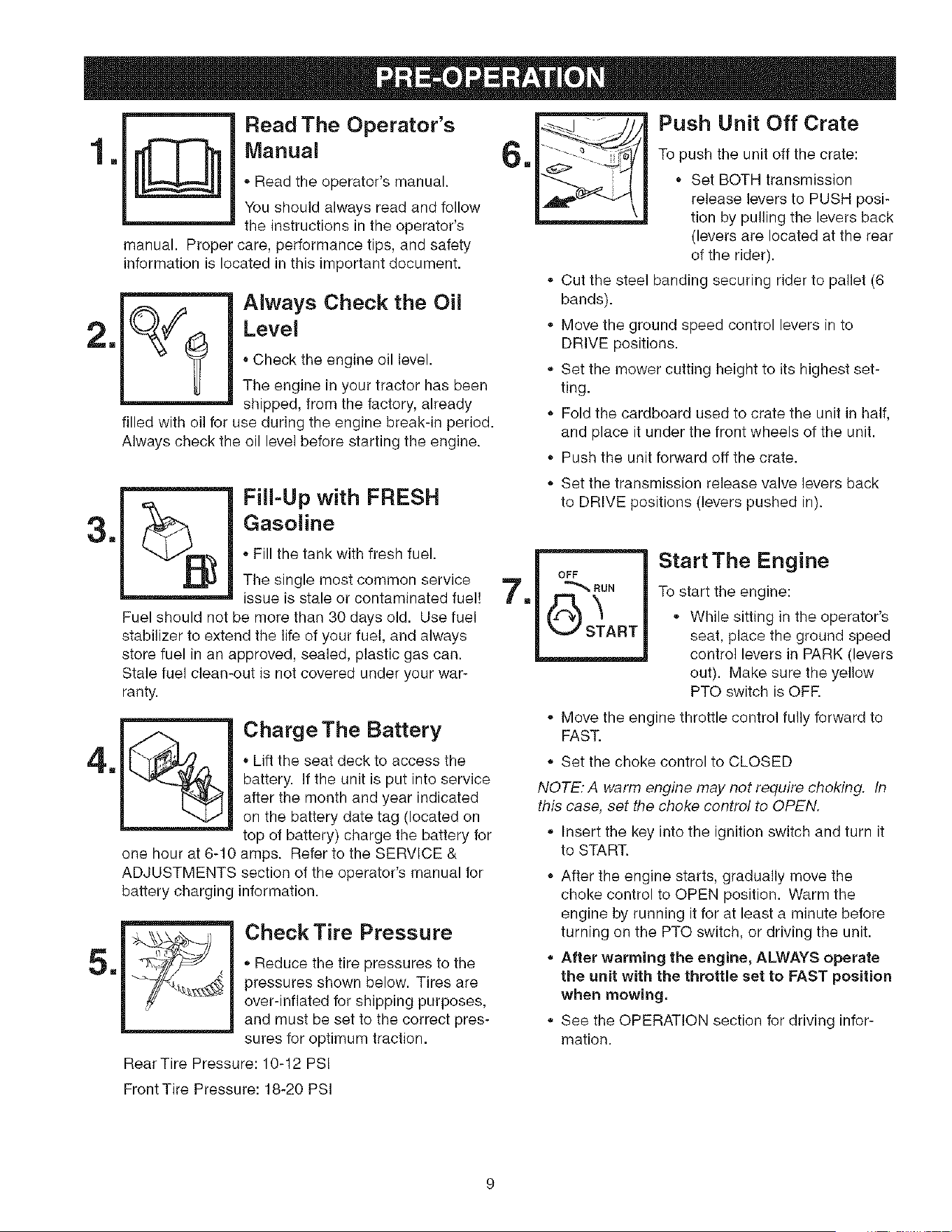
Read The Operator's
Manual
* Read the operator's manual.
You should always read and follow
the instructions in the operator's
manual. Proper care, performance tips, and safety
information is located in this important document.
Always Cheek the Oil
Level
Check the engine oil level.
The engine in your tractor has been
shipped, from the factory, already
filled with oil for use during the engine break-in period.
Always check the oil level before starting the engine.
m
Push Unit Off Crate
To push the unit off the crate:
Set BOTH transmission
release levers to PUSH posi-
tion by pulling the levers back
(levers are located at the rear
of the rider).
Cut the steel banding securing rider to pallet (8
bands).
Move the ground speed control levers in to
DRIVE positions.
Set the mower cutting height to its highest set-
ting.
Fold the cardboard used to crate the unit in half,
and place it under the front wheels of the unit.
• Push the unit forward off the crate.
m
4m
5m
Fill-Up with FRESH
Gasoline
Fill the tank with fresh fuel.
The single most common service
issue is stale or contaminated fuel!
Fuel should not be more than 30 days old. Use fuel
stabilizer to extend the life of your fuel, and always
store fuel in an approved, sealed, plastic gas can.
Stale fuel clean-out is not covered under your war-
ranty.
%
Charge The Battery
Lift the seat deck to access the
battery. If the unit is put into service
after the month and year indicated
on the battery date tag (located on
top of battery) charge the battery for
one hour at 8-10 amps. Refer to the SERVICE &
ADJUSTMENTS section of the operator's manual for
battery charging information.
Check Tire Pressure
Reduce the tire pressures to the
pressures shown below. Tires are
over-inflated for shipping purposes,
and must be set to the correct pres-
sures for optimum traction.
RearTire Pressure: 10-12 PS!
Set the transmission release valve levers back
to DRIVE positions (levers pushed in).
m
OFF
RUN
O START
Start The Engine
To start the engine:
While sitting in the operator's
seat, place the ground speed
control levers in PARK (levers
out). Make sure the yellow
PTO switch is OFR
• Move the engine throttle control fully forward to
FAST.
Set the choke control to CLOSED
NOTE: A warm engine may not require choking. In
this case, set the choke control to OPEN.
Insert the key into the ignition switch and turn it
to START.
After the engine starts, gradually move the
choke control to OPEN position. Warm the
engine by running it for at least a minute before
turning on the PTO switch, or driving the unit.
After warming the engine, ALWAYS operate
the unit with the throttle set to FAST position
when mowing,
. See the OPERATION section for driving infor-
mation.
Front Tire Pressure: 18-20 PSI
9
Right
GroundSpeed&
ParkingBrake
Lever
Throttle
(Fast)
Throttle
ilow)
r
N,-',(®)
Cap
Choke
(Closed)
l C,oke
(Open)
GroundSpeedLevers- GroundSpeedLevers-
DRIVEPesitons PARKPesitoes
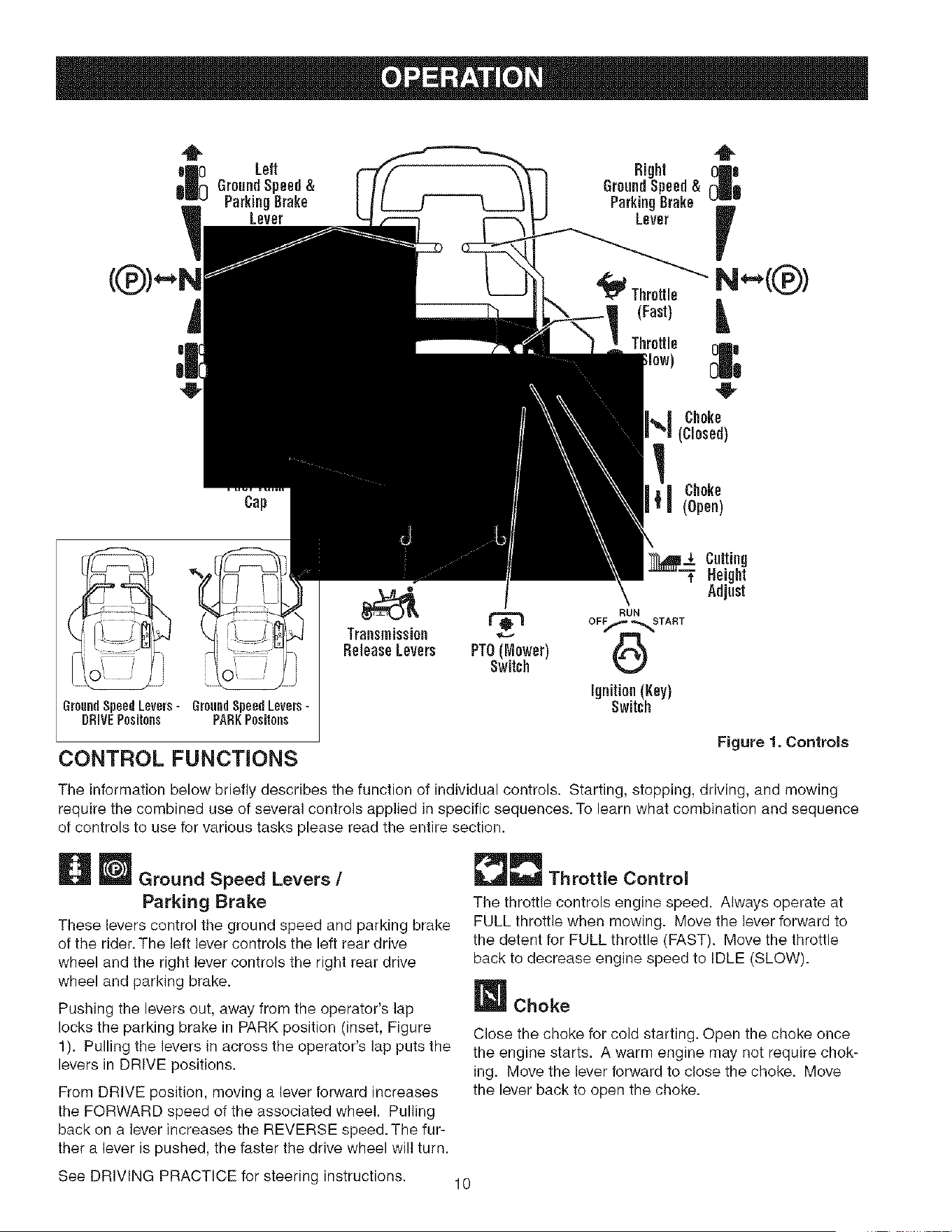
CONTROL FUNCTIONS
r_ RUN
Transmission _
ReleaseLevers PTO(Mower)
Switch
ignition(Key)
Switch
Cutting
Height
Adjust
Figure 1. Controls
The information below briefly describes the function of individual controls. Starting, stopping, driving, and mowing
require the combined use of several controls applied in specific sequences. To learn what combination and sequence
of controls to use for various tasks please read the entire section.
Ground Speed Levers /
Parking Brake
These levers control the ground speed and parking brake
of the rider. The left lever controls the left rear drive
wheel and the right lever controls the right rear drive
wheel and parking brake.
Pushing the levers out, away from the operator's lap
locks the parking brake in PARK position (inset, Figure
1). Pulling the levers in across the operator's lap puts the
levers in DRIVE positions.
From DRIVE position, moving a lever forward increases
the FORWARD speed of the associated wheel. Pulling
back on a lever increases the REVERSE speed. The fur-
ther a lever is pushed, the faster the drive wheel will turn.
[]'_- Throttle Control
The throttle controls engine speed. Always operate at
FULL throttle when mowing. Move the lever forward to
the detent for FULL throttle (FAST). Move the throttle
back to decrease engine speed to IDLE (SLOW).
W Choke
Close the choke for cold starting. Open the choke once
the engine starts. A warm engine may not require chok-
ing. Move the lever forward to close the choke. Move
the lever back to open the choke.
See DRIVING PRACTICE for steering instructions. 10
Mower Height of Cut Adjustment
To adjust cutting height, rotate the turn crank clockwise
to raise the mower deck and counterclockwise to lower
the mower deck.
ignition Switch
The ignition switch starts and stops the engine; it has
three positions:
OFF Stops the engine and shuts off the
electrical system.
BUN Allows the engine to run and powers the
electrical system.
START Cranks the engine for starting.
NOTE: Never leave the ignition switch in the RUN posi-
tion with the engine stopped. This drains the batter_4
[]Hour Meter
The hour meter measures the number of hours the key
has been in the RUN position.
NOTE: The hour meter will register the passage of time
when the key is in the RUN position, even if the engine is
not running.
_PTO Switch
The PTO (Power Take-Off) switch engages and disen-
gages the mower deck. To turn the mower on, pull the
switch UP. Push the switch DOWN to turn the mower off.
Note that the operator must be seated firmly in the rider
seat for the PTO to function.
Transmission Release Levers
The transmission release levers deactivate the transmis-
sions so that the unit can be pushed by hand. See
PUSHING THE UNIT BY HAND for operational informa-
tion.
FueJ Tank
To remove the cap, turn counterclockwise.
GENERAL OPERATING SAFETY
Before first time operation:
Be sure to read all information in the Safety and
Operation sections before attempting to operate this
rider and mower.
Become familiar with all of the controls and how to stop
the unit.
Drive in an open area without mowing to become accus-
tomed to driving the unit.
,WARNING
if you do not understand how a specific control
functions, or have not yet thoroughly read the
CONTROL FUNCTIONS section, do so now.
Do NOT attempt to operate the rider without first
becoming familiar with the location and function
of ALL controls,
11

CHECKS BEFORE STARTING
• Check that the crankcase oil is filled to full mark on
dipstick.
Fill the fuel tank with fresh fuel.
FUEL RECOMMENDATIONS
For daily operation: Use only unleaded gasoline with a
pump sticker octane rating of 87 or higher. Gasohol (up
to 10% ethyl alcohol, 90% unleaded gasoline by volume)
is approved as a fuel. Methyl Tedary Butyl Ether (MTBE)
and unleaded gasoline blends (up to a maximum of 15%
MTBE by volume) are approved as a fuel. No other gaso-
line/alcohol or gasoline/ether blends are approved. Do
not use fuel additives other than fuel stabilizer.
For storage: CAUTION: Alcohol blended fuels (called
gasohol or using ethanol or methanol) can attract mois-
ture which leads to separation and formation of acids
during storage. Acidic gas can damage the fuel system
of an engine while in storage.
To avoid engine problems always use fuel stabilizer,
especially before storage of 30 days or longer. Use fresh
fuel next season. See STORAGE instructions for addi-
tional information.
Never use engine or carburetor cleaner products in the
fuel tank or permanent damage may occur.To add fuel:
1. Remove the fuel cap (B, Figure 2).
2. Fill the tank. Do not overfill. Leave room in the tank
for fuel expansion.
3. Install and hand tighten the fuel cap.
Figure 2. Pre=Start Checks
A. Fuel Tank Cap
WARNING
Never operate on slopes greater than 17.6 percent
(10 °) which is a rise of 3-1/2 feet (106 cm)
vertically in 20 feet (607 cm) horizontally.
Select slow ground speed before driving onto a
slope. Use extra caution when operating on
slopes with a rear-mounted grass catcher.
Mow across the of slopes, not up and down. Use
caution when changing directions and DO NOT
START OR STOP ON A SLOPE.
,WARNING
Never allow passengers to ride on the unit.
Before leaving the operator's position for any
reason, engage the parking brake, disengage the
PTO, stop the engine and remove the key.
To reduce fire hazard, keep the engine, rider and
mower free of grass, leaves and excess grease.
Do not stop or park rider over dry leaves, grass or
combustible materials.
Gasoline is highly flammable and must be
handled with care. Never fill the tank when the
engine is still hot from recent operation. Do not
allow open flame, smoking or matches in the area.
Avoid over-filling and wipe up any spills.
WARNING =TRAILERS
Do not load this zero-turn rider on a trailer or
truck using two separate ramps. Only use a
single ramp that is at least one foot wider than
the width of the rear wheels of this rider. This
rider has a zero turning radius and the wheels
could fall off the ramps, or the rider could tip over
injuring the operator or bystanders.
12
EMERGENCYSTOPPING
In the event of an emergency the engine can be stopped
by simply turning the ignition switch to STOR Use this
method only in emergency situations. For normal engine
shut down follow the procedure given in STOPPING THE
RIDER AND ENGINE.
STOPPING THE RIDER & ENGINE
7. Begin mowing. See DRIVING PRACTICE.
8. When finished, turn the PTO switch OFE
9. Stop the engine (see STOPPING THE RIDER AND
ENGINE).
PUSHING THE RIDER BY HAND
1.
1. Returning the ground speed control levers to PARK
positions will stop rider movement and engage the 2.
parking brake.
2. Stop the mower by pushing down on the PTO switch. 3.
3. Briggs & Stratton Models: Move the throttle control
to SLOW position and turn the ignition key to OFR 4.
Remove the key.
Kohler Models: Move the throttle control to FAST
position and turn the ignition key to OFR Remove the
key. 5.
STARTING THE ENGINE
1. While sitting in the operator's seat, make sure the
PTO switch is OFF and the ground speed control
levers are locked in PARK positions.
2. Move the engine throttle control fully forward to FAST.
Set the choke control to CLOSED.
NOTE: A warm engine may not require choking. In this
case, set the choke control to OPEN.
3. Insert the key into the ignition switch and turn it to
START.
4. After the engine starts, gradually move the choke
control back to OPEN position. Warm the engine by
running it for at least a minute before turning on the
PTO switch, or driving the unit.
5. After warming the engine, ALWAYS operate the
unit with the throttle set to FAST, especially when
mowing.
MOWING
1. Make sure the PTO switch is OFF, the ground speed
control levers are locked in their PARK positions, and
the operator is in the seat.
2. Set the mower cutting height to the desired setting.
3. Start the engine (see STARTING THE ENGINE).
4. Set the throttle to FAST.
5. Turn the PTO switch ON to engage the mower deck.
6. Move the ground speed control levers from PARK
positions to drive positions (levers in across the oper-
ator's lap).
Turn the PTO switch OFF, set the ground speed con-
trol levers to PARK, turn the ignition switch OFF,
remove the key, and wait for all moving parts to stop.
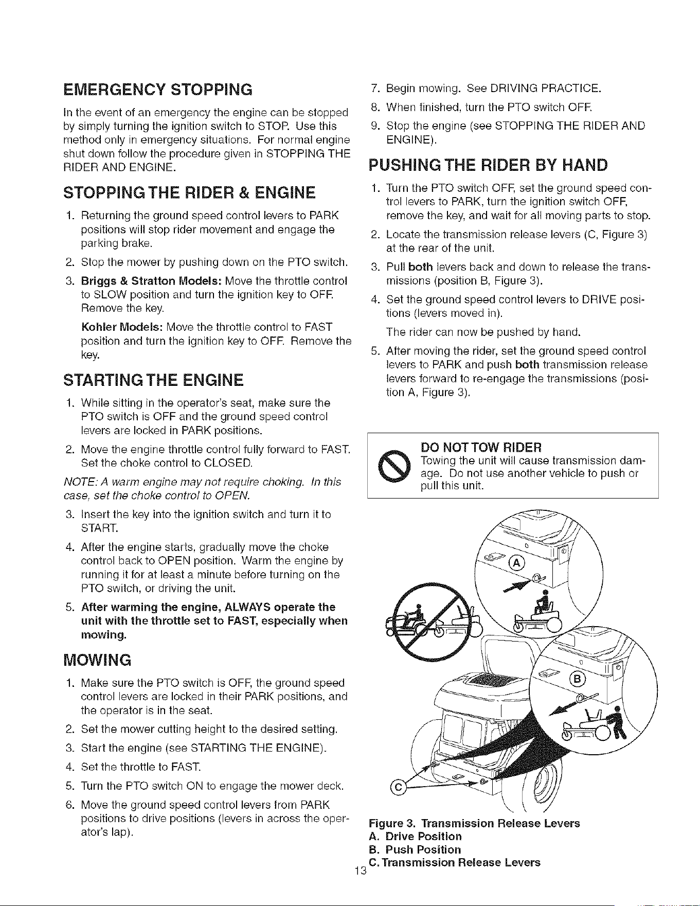
Locate the transmission release levers (C, Figure 3)
at the rear of the unit.
Pull both levers back and down to release the trans-
missions (position B, Figure 3).
Set the ground speed control levers to DRIVE posi-
tions (levers moved in).
The rider can now be pushed by hand.
After moving the rider, set the ground speed control
levers to PARK and push both transmission release
levers forward to re-engage the transmissions (posi-
tion A, Figure 3).
®
DO NOT TOW RIDER
Towing the unit will cause transmission dam-
age. Do not use another vehicle to push or
pull this unit.
Figure 3. Transmission Release Levers
A, Drive Position
B. Push Position
C. Transmission Release Levers
13
DRiViNG PRACTICE -
BASIC DRIVING
WARNING: Never operate on slopes greater than 17.6%
(10°). See SLOPE OPERATION in the safety section.
Zero turn riders operate differently from other four-
wheeled vehicles. The drive wheels are also your steer-
ing wheels. If you cannot drive the unit on a hill, you will
not be able to steer the unit on it. Operating zero turn
units on slopes requires extra caution.
The lever controls of the zero turn rider are very respon-
sive, and learning to gain a smooth and efficient control
of the rider's forward, reverse, and turning movements
will take some practice.
Spend some time going through the following maneuvers
and becoming familiar with how the unit accelerates,
travels, and steers -- before you begin mowing --is
absolutely essential to getting the most out of the zero
turn rider.
Locate a smooth, flat area of your lawn -- one with
plenty of room to maneuver. (Clear the area of objects,
people and animals before you begin.) Operate the unit
at mid-throttle during this practice session (ALWAYS
operate at full throttle when mowing), and turn slowly to
prevent tire slippage and damage to your lawn.
We suggest you begin with the Smooth Travel procedure
to the right, and then advance through the forward,
reverse, and turning maneuvers.
WARNING
Do not mow in reverse unless absolutely
necessary. Always look down and behind before
and while travelling in reverse,
Forward Travel _
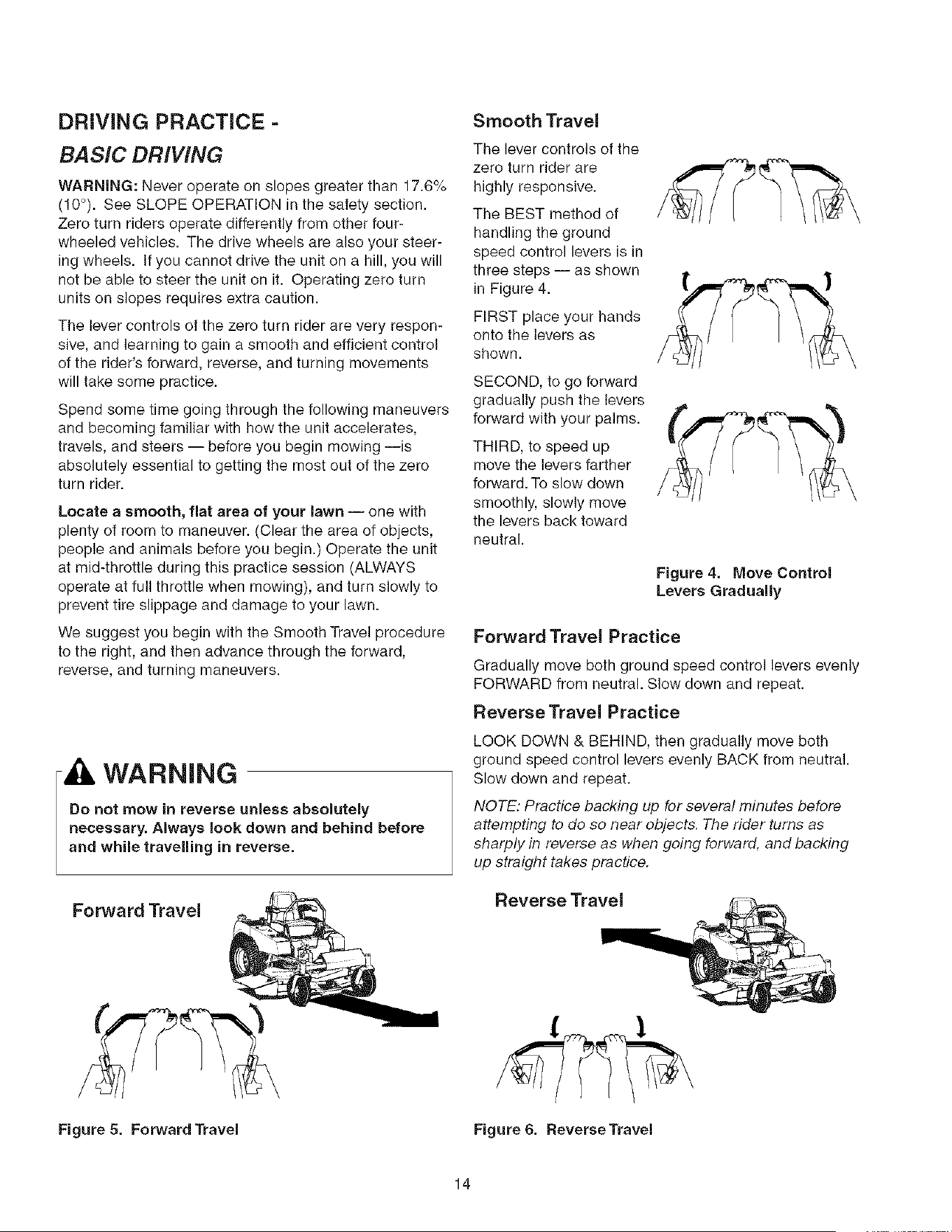
Smooth Travel
The lever controls of the
zero turn rider are
highly responsive.
The BEST method of
handling the ground
speed control levers is in
three steps -- as shown
in Figure 4.
FIRST place your hands
onto the levers as
shown.
SECOND, to go forward
gradually push the levers
forward with your palms.
THIRD, to speed up
move the levers farther
forward. To slow down
smoothly, slowly move
the levers back toward
neutral.
Figure 4. Move Control
Levers Gradually
Forward Travel Practice
Gradually move both ground speed control levers evenly
FORWARD from neutral. Slow down and repeat.
Reverse Travel Practice
LOOK DOWN & BEHIND, then gradually move both
ground speed control levers evenly BACK from neutral.
Slow down and repeat.
NOTE: Practice backing up for several minutes before
attempting to do so near objects. The rider turns as
sharply in reverse as when going forward, and backing
up straight takes practice.
Reverse Travel
Figure 5. Forward Travel Figure& Reverse Travel
14
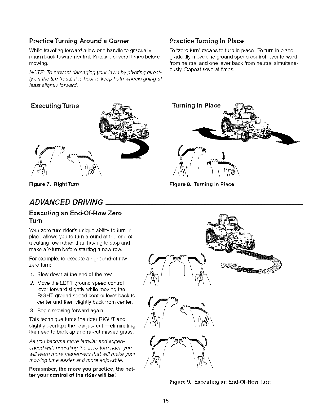
PracticeTurning Around a Corner
While traveling forward allow one handle to gradually
return back toward neutral. Practice several times before
mowing.
NOTE: To prevent damaging your lawn by pivoting direct-
lyon the tire tread, it is best to keep both wheels going at
least slightly forward.
PracticeTurning In Place
To "zero turn" means to turn in place. To turn in place,
gradually move one ground speed control lever forward
from neutral and one lever back from neutral simultane-
ously. Repeat several times.
Executing Turns
Figure 7. RightTurn Figure 8. Turning in Place
ADVANCED DRIVING
Executing an End-Of-Row Zero
Turn
Your zero turn rider's unique ability to turn in
place allows you to turn around at the end of
a cutting row rather than having to stop and
make a Y-turn before starting a new row.
For example, to execute a right end-of row
zero turn:
1. Slow down at the end of the row.
2. Move the LEFT ground speed control
lever forward slightly while moving the
RIGHT ground speed control lever back to
center and then slightly back from center.
3. Begin mowing forward again.
This technique turns the rider RIGHT and
slightly overlaps the row just cut --eliminating
the need to back up and re-cut missed grass.
As you become more familiar and experi-
enced with operating the zero turn rider, you
will learn more maneuvers that will make your
mowing time easier and more enjoyable.
Remember, the more you practice, the bet=
ter your control of the rider will be!
Figure 9. Executing an End-Of=RowTurn
15

MOWER DECK REMOVAL &
INSTALLATION
NOTE: Perform mower removal and installation on a
hard, level surface such as a concrete floor.
WARNING
Engage parking brake, disengage PTO, stop
engine and remove key before attempting to
install or remove the mower.
Removing the Mower Deck
1. Turn the PTO off, put the control levers in PARK posi-
tion, turn the ignition OFF, remove the key, and wait
for all moving parts to stop.
2. Pivot the rider's front wheels forward.
3. Place the cutting height adjustment crank (D, Figure
10) in the lowest cutting position.
4. Release tension on the drive belt using the mower
belt release lever (E, Figure 10) and remove the drive
belt from the engine pulley.
5. Disconnect the front hitch by removing the hitch rod
and clip (A, Figures 10 & 11), and lifting the mower
hitch (B) up and off the rider hitch bracket (D).
6. Slide the mower deck forward until the rear mower
supports (C) disengage the frame of the rider.
7. Slide the mower deck out from under the right side of
the rider.
Installing the Mower Deck
1. Pivot the rider's front wheels forward.
2. Place the cutting height adjustment crank (D, Figure 10)
in the lowest cutting position.
3. Slide the mower deck under the right side of the rider.
Slide the mower backwards making sure that the rear
mower supports (C, Figure 11) slide up the ramps on
the frame. The rear of the mower is supported by
these frame ramps.
4. Hang the mower hitch (B, Figure 11) on the rider
hitch bracket (D) and secure with the hitch rod and
clip (A).
5. Use the mower belt release lever (E, Figure 12) to
release tension on the mower idler pulley, and install
the drive belt as shown in Figure 12.
Figure 10. Mower Components
A. Hitch Rod and Clip
B. Mower Hitch
C. Rear Mower Supports
D. Cutting Height Adjustment Crank
E. Mower Belt Release Lever
Figure 11. Mower Hitch Components
A. Hitch Rod and Clip
B. Mower Hitch
C. Rear Mower Supports
D. Rider Hitch Bracket
Figure 12. Mower Belt Routing
A. Engine Pulley
B. Mower Drive Belt
C. Back=Side idler Pulley
D. V-idler Pulley
E. Mower Belt Release Lever
F. Mower Drive Pulley
16
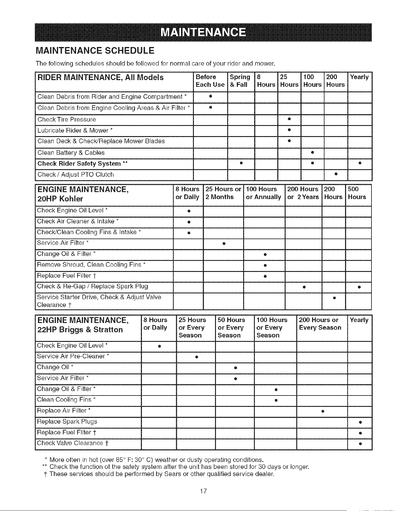
MAINTENANCE SCHEDULE
The following schedules should be followed for normal care of your rider and mower.
RNDER MAINTENANCE, All Models Before Spring 8 25 100 200 Yearly
Each Use & Fall Hours Hours Hours Hours
Clean Debris from Rider and Engine Compartment * •
Clean Debris from Engine Cooling Areas & Air Filter * •
Check Tire Pressure •
Lubricate Rider & Mower * •
Clean Deck & Check/Replace Mower Blades •
Clean Battery & Cables •
Check Hider Safety System ** • • •
Check / Adjust PTO Clutch •
ENGINE MAINTENANCE, 8 Hours 25 Hours or 100 Hours 200 Hours 200 500
20HPKohler orDaily 2Months orAnnually or 2Years Hours Hours
Check Engine Oil Level * •
Check Air Cleaner & Intake * •
Check/Clean Cooling Fins & Intake * ®
Service Air Filter * ®
Change Oil & Filter * •
Remove Shroud, Clean Cooling Fins * •
Replace Fuel Filter 1 •
Check & Re-Gap / Replace Spark Plug • •
Service Starter Drive, Check & Adjust Valve ®
Clearance 1-
ENGINE MAINTENANCE, 8 Hours 25 Hours 50 Hours 100 Hours 200 Hours or Yearly
22HP Briggs & Stratton or Daily or Every or Every or Every Every Season
Season Season SeasoR
Check Engine Oil Level * ®
Service Air Pre-Cleaner * ®
Change Oil * •
Service Air Filter * •
Change Oil & Filter * •
Clean Cooling Fins * •
Replace Air Filter * ®
Replace Spark Plugs •
Replace Fuel Filter i- ®
Check Valve Clearance 1- •
* More often in hot (over 85 ° F: 30 ° C) weather or dusty operating conditions.
** Check the function of the safety system after the unit has been stored for 30 days or longer.
i- These services should be performed by Sears or other qualified service dealer.
17
Rider Maintenance items
CLEAN DEBRIS FROM RIDER AND
ENGINE COMPARTMENT
Service interval: Before each use.
CAUTION: if debris is not removed from the engine
compartment and other hot surfaces, it creates a fire
hazard. Before starting the unit at the beginning of the
mowing session, remove any grass clippings, dirt,
leaves, or other debris from the unit. Also clean out the
engine compartment.
CLEAN DEBRIS FROM ENGINE
COOLING AREAS AND AIR FILTER
Service interval: Before each use.
CAUTION: If debris is not removed from the engine
compartment and other hot surfaces, it creates a fire
hazard. Before starting the unit at the beginning of the
mowing session, lift the seat deck and clean any debris
from the intake screen on top of the engine (A, Figure
13), exposed engine cooling fins, and around the air filter
assembly. Also open the air filter cover (B) and remove
any debris that has accumulated in the air filter compart-
ment.
CHECKTIRE PRESSURE
Service interval: 25 Hours.
Tire pressure should be checked periodically, and main-
tained at the levels shown in Figure 14. Note that these
pressures may differ slightly from the "Max Inflation"
stamped on the side-wall of the tires. The pressures
shown provide proper traction, improve cut quality, and
extend tire life.
\
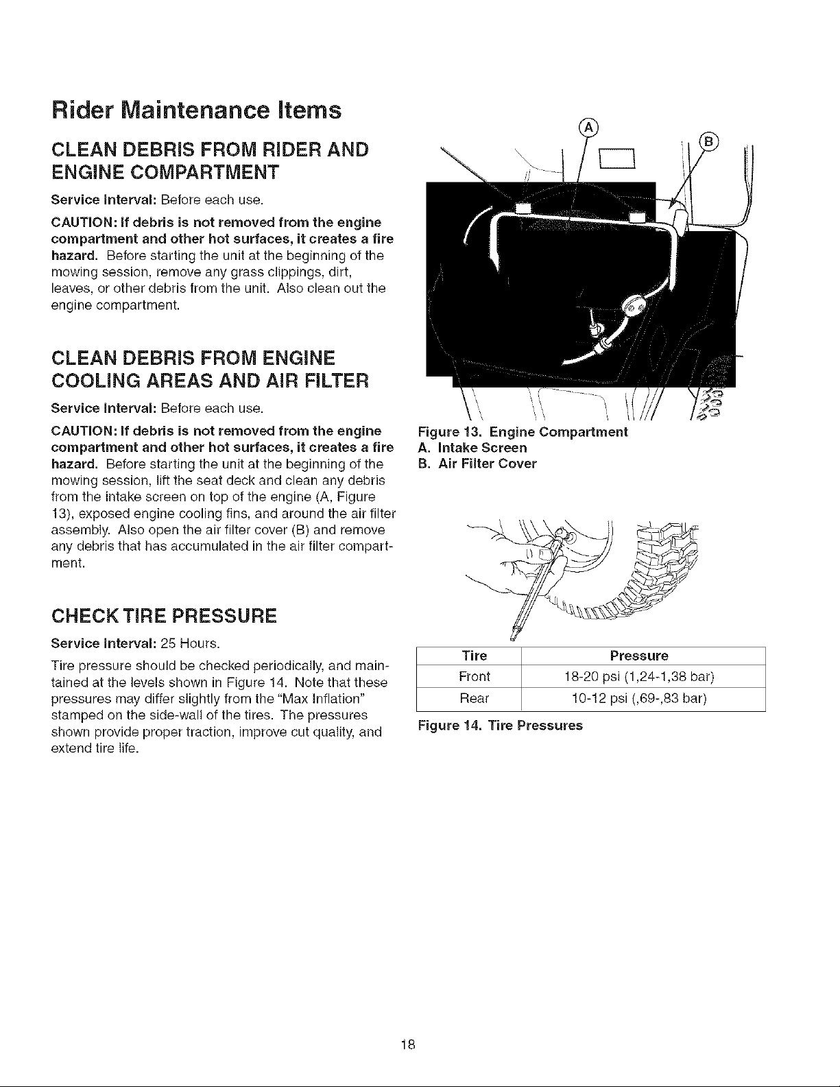
\
Figure 13. Engine Compartment
A. intake Screen
B. Air Filter Cover
Tire Pressure
Front 18-20 psi (1,24-1,38 bar)
Rear 10-12 psi (,69-,83 bar)
Figure 14. Tire Pressures
18
LUBRiCATiON
Service Interval: 25 hours.
Lubricate the unit at the locations shown in Figures 15
through 17 as well as the following lubrication points.
Grease:
• front wheel grease fittings
front wheel bushings
• mower pivots
mower arbors
Use grease fittings when present.
Not all greases are compatible. Use automotive4ype lithi-
um grease.
Oil:
• rear frame assembly pivot
hydro linkage
brake linkage
frame pivot points
• mower deck height adjustment linkage
obrake linkage
Generally, all moving metal parts should be oiled where
contact is made with other parts. Keep oil and grease off
belts and pulleys. Remember to wipe fittings and sur-
faces clean both before and after lubrication.
\\
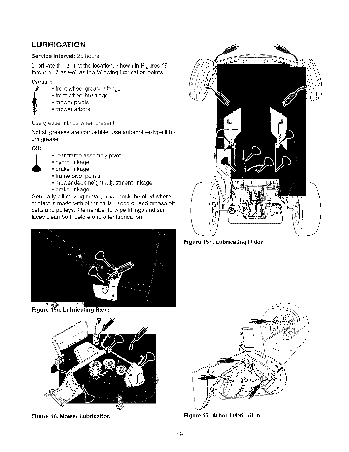
Figure 15a. Lubricating Rider
Figure 15b. Lubricating Rider
Figure 16. Mower Lubrication
Figure 17. Arbor Lubrication
19
CLEAN DECK &
CHECK / REPLACE MOWER BLADES
Service Interval: 25 hours or as required.
WARNING
For your personal safety, do not handle the sharp
mower blades with bare hands. Careless or
improper handling of blades may result in serious
injury.
WARNING
For your personal safety, blade mounting
capscrews must each be installed with a
hex/spline washer and spring washer, then
securely tightened. Torque blade mounting
capscrew to 45 - 55 ft. Ibs. (61 - 75 N.m.)
1. Remove mower deck (see "Mower Deck Removal" in
the OPERATION section).
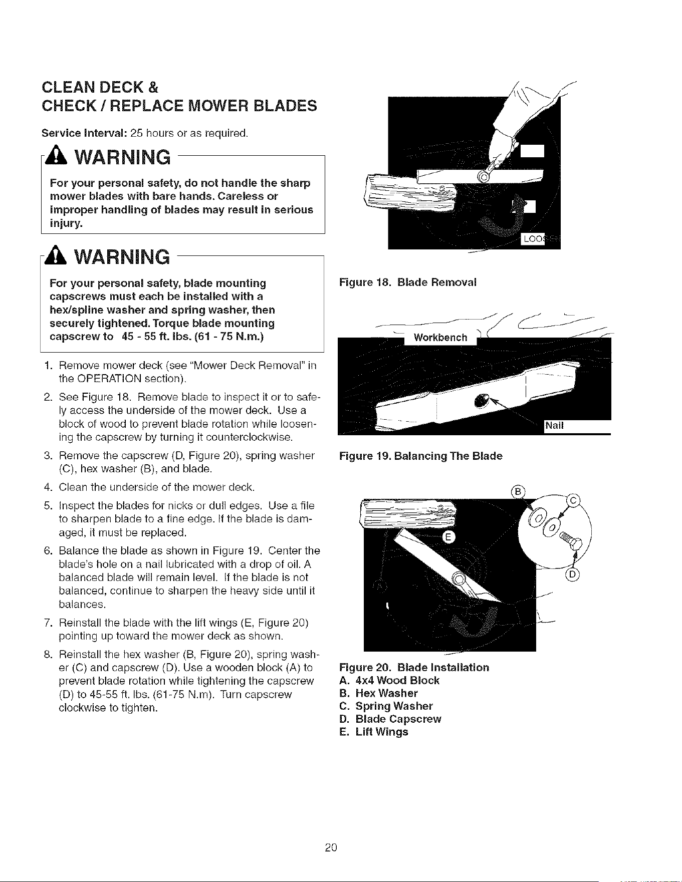
2. See Figure 18. Remove blade to inspect it or to safe-
ly access the underside of the mower deck. Use a
block of wood to prevent blade rotation while loosen-
ing the capscrew by turning it counterclockwise.
3. Remove the capscrew (D, Figure 20), spring washer
(C), hex washer (B), and blade.
4. Clean the underside of the mower deck.
5. Inspect the blades for nicks or dull edges. Use a file
to sharpen blade to a fine edge. If the blade is dam-
aged, it must be replaced.
6. Balance the blade as shown in Figure 19. Center the
blade's hole on a nail lubricated with a drop of oil. A
balanced blade will remain level. If the blade is not
balanced, continue to sharpen the heavy side until it
balances.
7. Reinstall the blade with the lift wings (E, Figure 20)
pointing up toward the mower deck as shown.
8. Reinstall the hex washer (B, Figure 20), spring wash-
er (C) and capscrew (D). Use a wooden block (A) to
prevent blade rotation while tightening the capscrew
(D) to 45-55 ft. Ibs. (61-75 N.m). Turn capscrew
clockwise to tighten.
Figure 18. Blade Removal
Workbench
Figure 19. Balancing The Blade
Figure 20. Blade Installation
A. 4x4 Wood Block
B. Hex Washer
C. Spring Washer
D. Blade Capscrew
E. Lift Wings
Nail
20
CLEANING THE BATTERY AND
CABLES
, WARNING
Be careful when handling the battery. Avoid
spilling electrolyte. Keep flames and sparks away
from the battery.
When removing or installing battery cables,
disconnect the negative cable FIRST and reconnect
it LAST. If not done in this order, the positive
terminal can be shorted to the frame by a tool
Always wear safety glasses and gloves when
handling batteries.
Service Interval: 100 Hours
1. Disconnect the cables from the battery, negative
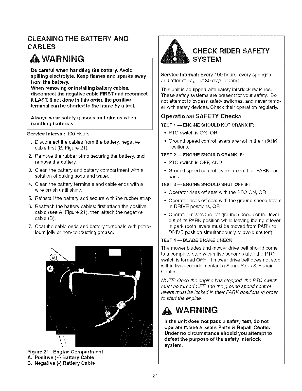
cable first (B, Figure 21 ).
2. Remove the rubber strap securing the battery, and
remove the battery.
3. Clean the battery and battery compartment with a
solution of baking soda and water.
4. Clean the battery terminals and cable ends with a
wire brush until shiny.
5. Reinstall the battery and secure with the rubber strap.
6. Reattach the battery cables: first attach the positive
cable (see A, Figure 21), then attach the negative
cable (B).
7. Coat the cable ends and battery terminals with petro-
leum jelly or non-conducting grease.
Figure 21. Engine Compartment
A. Positive (+) Battery Cable
B. Negative (-) Battery Cable
CHECK RIDER SAFETY
SYSTEM
Service interval: Every 100 hours, every spring/fall,
and after storage of 30 days or longer.
This unit is equipped with safety interlock switches.
These safety systems are present for your safety. Do
not attempt to bypass safety switches, and never tamp-
er with safety devices. Check their operation regularly.
Operational SAFETY Checks
TEST 1 -- ENGINE SHOULD NOT CRANK IF:
PTO switch is ON, OR
• Ground speed control levers are not in their PARK
positions.
TEST 2 -- ENGINE SHOULD CRANK IF:
• PTO switch is OFF, AND
Ground speed control levers are in their PARK posi-
tions.
TEST 3 -- ENGINE SHOULD SHUT OFF IF:
Operator rises off seat with the PTO ON, OR
Operator rises off seat with the ground speed levers
in DRIVE positions, OR
Operator moves the left ground speed control lever
out of its PARK position while leaving the right lever
in park (both levers must be moved from PARK to
DRIVE position simultaneously to avoid shutoff).
TEST 4 -- BLADE BRAKE CHECK
The mower blades and mower drive belt should come
to a complete stop within five seconds after the PTO
switch is turned OFR If mower drive belt does not stop
within five seconds, contact a Sears Parts & Repair
Center.
NOTE: Once the engine has stopped, the PTO switch
must be turned OFF and the ground speed control
levers must be locked in their PARK positions in order
to start the engine.
WARNING
if the unit does not pass a safety test, do not
operate it. See a Sears Parts & Repair Center.
Under no circumstance should you attempt to
defeat the purpose of the safety interlock
system,
21
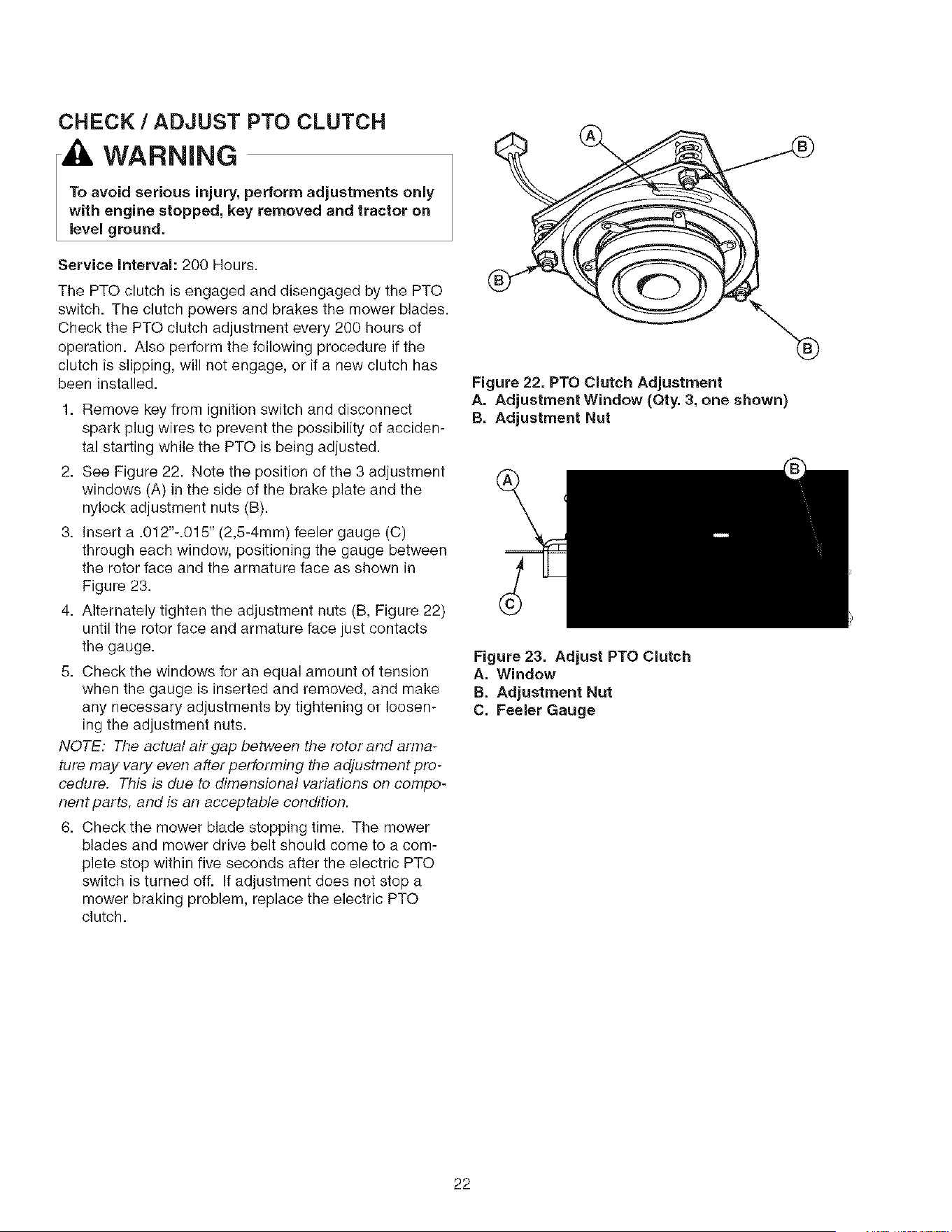
CHECK / ADJUST PTO CLUTCH
WARNING
To avoid serious injury, perform adjustments only
with engine stopped, key removed and tractor on
level ground.
Service Interval: 200 Hours.
The PTO clutch is engaged and disengaged by the PTO
switch. The clutch powers and brakes the mower blades.
Check the PTO clutch adjustment every 200 hours of
operation. Also perform the following procedure if the
clutch is slipping, will not engage, or if a new clutch has
been installed.
1. Remove key from ignition switch and disconnect
spark plug wires to prevent the possibility of acciden-
tal starting while the PTO is being adjusted.
2. See Figure 22. Note the position of the 3 adjustment
windows (A) in the side of the brake plate and the
nylock adjustment nuts (B).
3. Insert a .012"-.015" (2,5-4mm) feeler gauge (C)
through each window, positioning the gauge between
the rotor face and the armature face as shown in
Figure 23.
4. Alternately tighten the adjustment nuts (B, Figure 22)
until the rotor face and armature face just contacts
the gauge.
5. Check the windows for an equal amount of tension
when the gauge is inserted and removed, and make
any necessary adjustments by tightening or loosen-
ing the adjustment nuts.
NOTE: The actual air gap between the rotor and arma-
ture may vary even after performing the adjustment pro-
cedure. This is due to dimensional variations on compo-
nent parts, and is an acceptable condition.
6. Check the mower blade stopping time. The mower
blades and mower drive belt should come to a com-
plete stop within five seconds after the electric PTO
switch is turned off. If adjustment does not stop a
mower braking problem, replace the electric PTO
clutch.
Figure 22. PTO Clutch Adjustment
A. Adjustment Window (Qty. 3, one shown)
B. Adjustment Nut
Figure 23. Adjust PTO Clutch
A. Window
B. Adjustment Nut
C. Feeler Gauge
22

Engine Maintenance Items
CHECK ENGINE OIL LEVEL -
KOHLER MODELS
Service interval: Before each use, and every 8 hours.
1. Turn the engine off, and set the ground speed con-
trois to PARK. Park on a level surface. Allow the
engine to cool.
2. Clean the area around the dip stick (C, Figure 25).
3. Remove the dip stick (C) and clean it with a paper
towel.
4. Insert the dip stick back into the engine, and push
firmly into place.
5. Remove the dip stick and read the oil level. The oil
level should be between the "F" and "i_' marks (D). if
not, add oil according to the oil recommendations
chart (Figure 24).
CHANGE ENGINE OIL & FILTER -
KOHLER MODELS
Service Interval: 100 Hours.
Oil Capacity: 1.6 Quarts (1.SL) with oil filter change.
Note: Change engine oil while the engine is warm. Run
the engine for a few minutes, then shut the engine off
and allow it to cool.
1. Clean the area around the dip stick (C, Figure 25)
and oil drain (A).
2. Remove the oil drain plug (A) and dip stick (C). Allow
ample time for complete drainage.
3. Remove the oil filter (B). Discard the filter.
4. Turn the new filter upside down and fill with fresh
engine oil. Allow the oil to seep into the new filter for
two minutes.
5. Using a drop of oil on your finger tip, wet the rubber
gasket on the bottom of the new filter.
6. Dump the oil out of the filter and install the filter on
the filter base. Turn the filter clockwise until the rub-
ber gasket meets the filter base. Then turn 2/3 to 1
full turn more.
7. Reinstall the oil drain plug (A) and route the oil drain
hose along side the engine.
8. Fill the crankcase with oil. See CHECK ENGINE OIL
LEVEL above.
9. Test run the engine to check for leaks. Stop the
engine for 1 minute, then recheck the oil level.
Use 0il classified API Service ClassSG,
SH, SJ or better with SAE Viscosity:
E Ej,
_4ENm _
-_0 ; ;31; ; 00 1;0
]C -30 -18 -7 0 4 16 27 38
I _Recomrnended:S_*ntheticoils provide better starting below-10"R
Figure 24, Recommended Engine Oil - KoMer Models
Figure 25. Oil Change = Kohler Models
A. Oil Drain Tube
B. Oil Filter
C. Dip Stick
D. Checking Oil Level
23
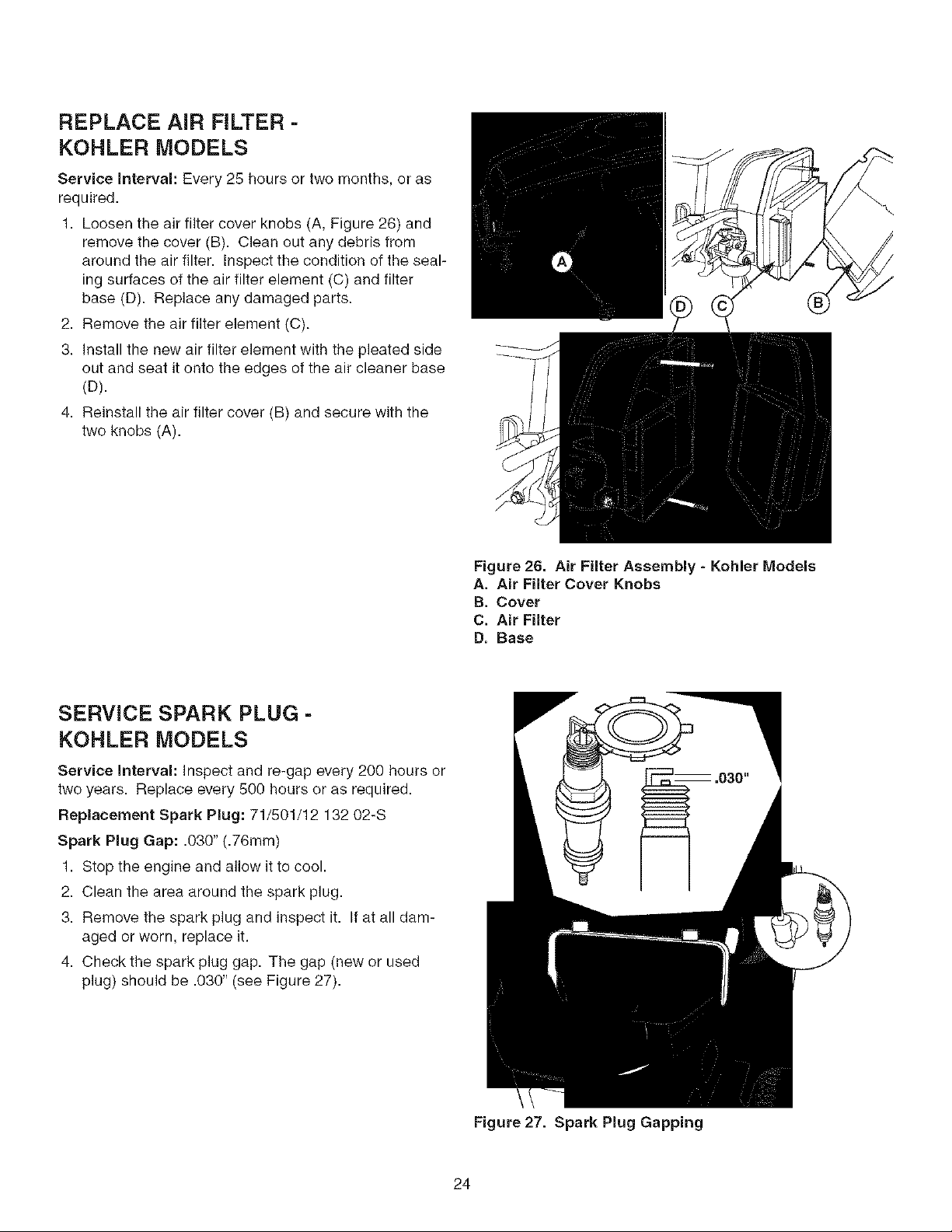
REPLACE AIR FILTER -
KOHLER MODELS
Service Interval: Every 25 hours or two months, or as
required.
1. Loosen the air filter cover knobs (A, Figure 2G) and
remove the cover (B). Clean out any debris from
around the air filter. Inspect the condition of the seal-
ing surfaces of the air filter element (C) and filter
base (D). Replace any damaged parts.
2. Remove the air filter element (C).
3. Install the new air filter element with the pleated side
out and seat it onto the edges of the air cleaner base
(D).
4. Reinstall the air filter cover (B) and secure with the
two knobs (A).
\\
Figure 26. Air Filter Assembly - Kohler Models
A. Air Filter Cover Knobs
B. Cover
C. Air Filter
D. Base
SERVICE SPARK PLUG -
KOHLER MODELS
Service interval: Inspect and re-gap every 200 hours or
two years. Replace every 500 hours or as required.
Replacement Spark Plug: 71/501/12 132 02-S
Spark Plug Gap: .030" (.76mm)
1. Stop the engine and allow it to cool.
2. Clean the area around the spark plug.
3. Remove the spark plug and inspect it. If at all dam-
aged or worn, replace it.
4. Check the spark plug gap. The gap (new or used
plug) should be .030" (see Figure 27).
Figure 27. Spark Plug Gapping
24
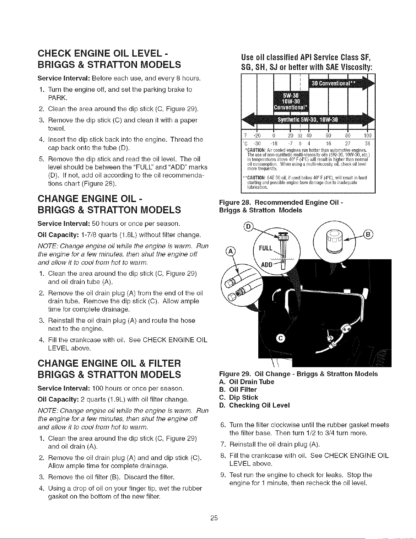
CHECK ENGINE OIL LEVEL -
BRIGGS & STRATTON MODELS
Service interval: Before each use, and every 8 hours.
1. Turn the engine off, and set the parking brake to
PARK.
2. Clean the area around the dip stick (C, Figure 29).
3. Remove the dip stick (C) and clean it with a paper
towel.
4. Insert the dip stick back into the engine. Thread the
cap back onto the tube (D).
8. Remove the dip stick and read the oil level. The oil
level should be between the "FULL:' and "ADD" marks
(D). If not, add oil according to the oil recommenda-
tions chart (Figure 28).
CHANGE ENGINE OIL -
BRIGGS & STRATTON MODELS
Service interval: 50 hours or once per season.
Oil Capacity: 1-7/8 quarts (1.8L) without filter change.
NOTE: Change engine oil while the engine is warm. Run
the engine for a few minutes, then shut the engine off
and allow it to cool from hot to warm.
1. Clean the area around the dip stick (C, Figure 29)
and oil drain tube (A).
2. Remove the oil drain plug (A) from the end of the oil
drain tube. Remove the dip stick (C). Allow ample
time for complete drainage.
3. Reinstall the oil drain plug (A) and route the hose
next to the engine.
4. Fill the crankcase with oil. See CHECK ENGINE OIL
LEVEL above.
CHANGE ENGINE OIL & FILTER
BRiGGS & STRATTON MODELS
Service Interval: 100 hours or once per season.
Oil Capacity: 2 quarts (1.9L) with oil filter change.
NOTE: Change engine oil while the engine is warm. Run
the engine for a few minutes, then shut the engine off
and allow it to cool from hot to warm.
1. Clean the area around the dip stick (C, Figure 29)
and oil drain (A).
2. Remove the oil drain plug (A) and and dip stick (C).
Allow ample time for complete drainage.
3. Remove the oil filter (B). Discard the filter.
4. Using a drop of oil on your finger tip, wet the rubber
gasket on the bottom of the new filter.
Useoil classifiedAPIService Class SF,
SG, SH, SJ or betterwith SAEViscosity:
F -J0 _ 2'03'24'0 G'0 _0 1_0
O -30 -18 -7 0 4 16 27 38
*CAUTION:Air cooled engines run hotter than _utomofive encnes.
The use of non-synthetic multi-viscosit;_ oils (5W=30,10W-30, etc.)
in temperatures above 400F (4°0) wH]resuMhi higher than normal
oil consumption. When using a multi-viscos_y oil, check oil level
more frequently.
** o o
CA!lTI0il: SAE 30 oil, if used below 40 F (4 C), will result ill hard
starting and possible engine bore damage due to inadequate
b_brication.
Figure 28, Recommended Engine Oil -
Briggs & Stratton Models
Figure 29. Oil Change - Briggs & Stratton Models
A. Oil Drain Tube
B. Oil Filter
C. Dip Stick
D. Checking Oil Level
6. Turn the filter clockwise until the rubber gasket meets
the filter base. Then turn 1/2 to 3/4 turn more.
7. Reinstall the oil drain plug (A).
8. Fill the crankcase with oil. See CHECK ENGINE OIL
LEVEL above.
9. Test run the engine to check for leaks. Stop the
engine for 1 minute, then recheck the oil level.
28
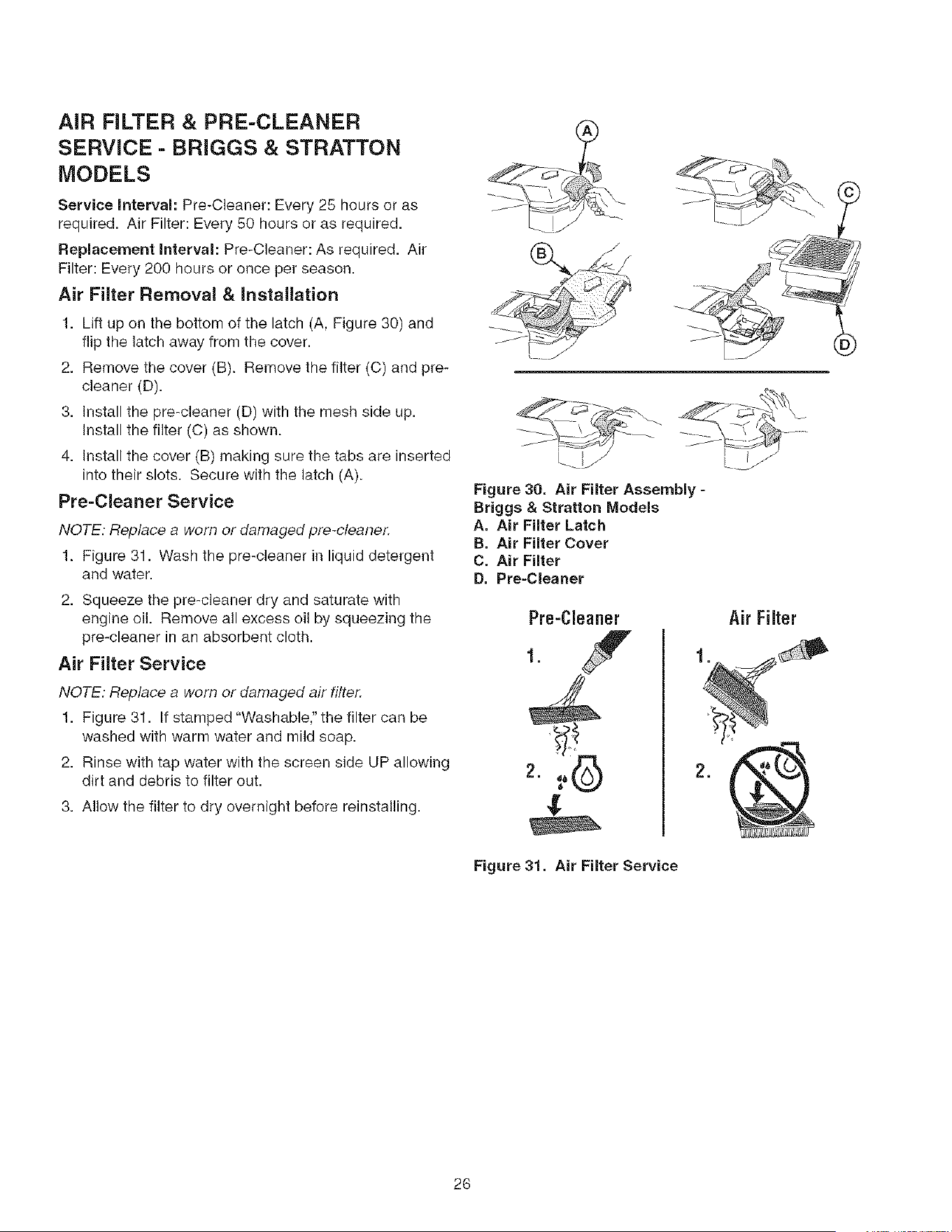
AiR FILTER & PRE-CLEANER
SERVICE - BRIGGS & STRATTON
MODELS
Service Interval: Pre-Cleaner: Every 25 hours or as
required. Air Filter: Every 50 hours or as required.
Replacement Interval: Pre_Cleaner: As required. Air
Filter: Every 200 hours or once per season.
Air Filter Removal & Installation
1. Lift up on the bottom of the latch (A, Figure 30) and
flip the latch away from the cover.
2. Remove the cover (B). Remove the filter (C) and pre-
cleaner (D).
3. Install the pre-cleaner (D) with the mesh side up.
Install the filter (C) as shown.
4. Install the cover (B) making sure the tabs are inserted
into their slots. Secure with the latch (A).
Pre-Cleaner Service
NOTE: Replace a worn or damaged pre-cteaner.
1. Figure 31. Wash the pre-cleaner in liquid detergent
and water.
2. Squeeze the pre-cleaner dry and saturate with
engine oil. Remove all excess oil by squeezing the
pre-cleaner in an absorbent cloth.
Air Filter Service
NOTE: Replace a worn or damaged air filter.
1. Figure 31. If stamped "Washable," the filter can be
washed with warm water and mild soap.
2. Rinse with tap water with the screen side UP allowing
dirt and debris to filter out.
3. Allow the filter to dry overnight before reinstalling.
Figure 30, Air Filter Assembly -
Briggs & Stratton Models
A, Air Filter Latch
B, Air Filter Cover
C. Air Filter
D, Pre-Cleaner
Pre-Cleaner
1.
Figure 31, Air Filter Service
-b
Air Filter
26

REPLACE SPARK PLUG -
BRIGGS & STRATTON MODELS
Service interval: Yearly
Replacement Spark Plug: 71/500/691043
Spark Plug Gap: .030" (.76mm)
1. Stop the engine and allow it to cool.
2. Clean the area around the spark plug.
3. Remove the spark plug.
4. Check the spark plug gap. It should be .030" (see
Figure 32).
5. Reinstall the plug into the cylinder head. Torque the
plug to 180 in. Ibs (20 N.m.).
Figure 32, Spark Plug Gapping
27
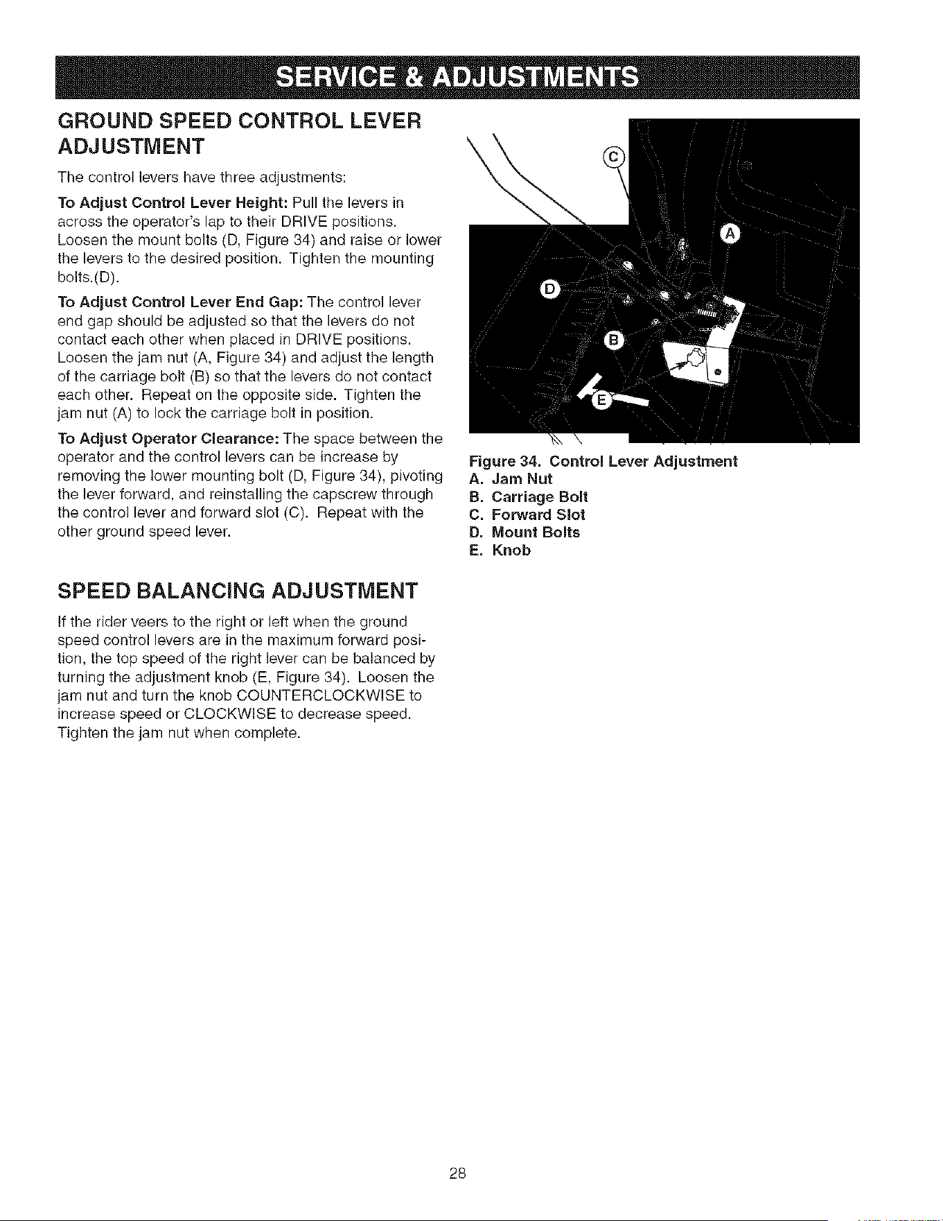
GROUND SPEED CONTROL LEVER
ADJUSTMENT
The control levers have three adjustments:
To Adjust Control Lever Height: Pull the levers in
across the operator's lap to their DRIVE positions.
Loosen the mount bolts (D, Figure 34) and raise or lower
the levers to the desired position. Tighten the mounting
bolts.(D).
To Adjust Control Lever End Gap: The control lever
end gap should be adjusted so that the levers do not
contact each other when placed in DRIVE positions.
Loosen the jam nut (A, Figure 34) and adjust the length
of the carriage bolt (B) so that the levers do not contact
each other. Repeat on the opposite side. Tighten the
jam nut (A) to lock the carriage bolt in position.
To Adjust Operator Clearance: The space between the
operator and the control levers can be increase by
removing the lower mounting bolt (D, Figure 34), pivoting
the lever forward, and reinstalling the capscrew through
the control lever and forward slot (C). Repeat with the
other ground speed lever.
\
Figure 34. Control Lever Adjustment
A. Jam Nut
B. Carriage Bolt
C. Forward Slot
D. Mount Bolts
E. Knob
SPEED BALANCING ADJUSTMENT
If the rider veers to the right or left when the ground
speed control levers are in the maximum forward posi-
tion, the top speed of the right lever can be balanced by
turning the adjustment knob (E, Figure 34). Loosen the
jam nut and turn the knob COUNTERCLOCKWISE to
increase speed or CLOCKWISE to decrease speed.
Tighten the jam nut when complete.
28
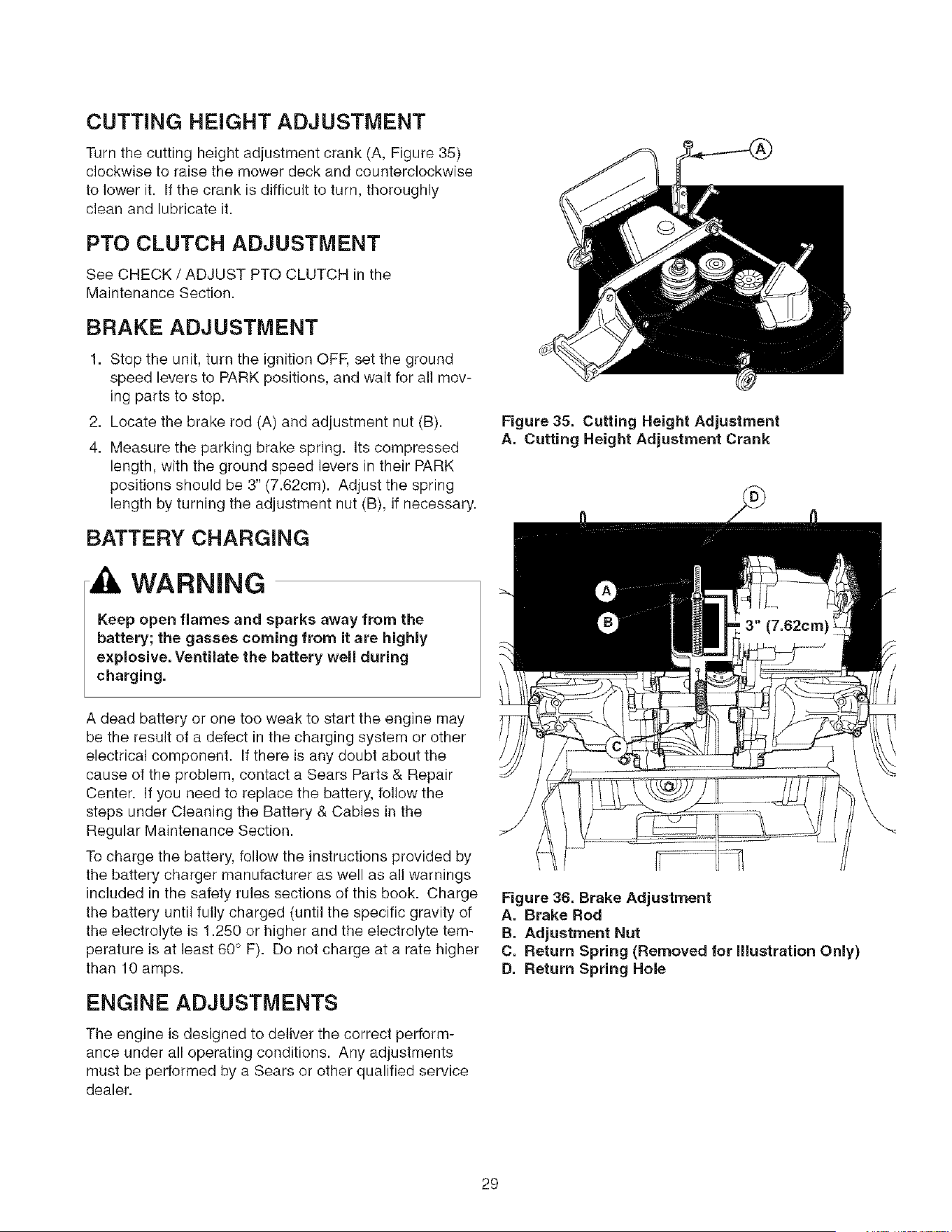
CUTTING HEIGHT ADJUSTMENT
Turn the cutting height adjustment crank (A, Figure 35)
clockwise to raise the mower deck and counterclockwise
to lower it. If the crank is difficult to turn, thoroughly
clean and lubricate it.
PTO CLUTCH ADJUSTMENT
See CHECK / ADJUST PTO CLUTCH in the
Maintenance Section.
BRAKE ADJUSTMENT
1. Stop the unit, turn the ignition OFF, set the ground
speed levers to PARK positions, and wait for all mov-
ing parts to stop.
2. Locate the brake rod (A) and adjustment nut (B).
4. Measure the parking brake spring. Its compressed
length, with the ground speed levers in their PARK
positions should be 3" (7.62cm). Adjust the spring
length by turning the adjustment nut (B), if necessary.
BATTERY CHARGING
WARNING
Keep open flames and sparks away from the
battery; the gasses coming from it are highly
explosive. Ventilate the battery well during
charging.
A dead battery or one too weak to start the engine may
be the result of a defect in the charging system or other
electrical component. If there is any doubt about the
cause of the problem, contact a Sears Parts & Repair
Center. If you need to replace the battery, follow the
steps under Cleaning the Battery & Cables in the
Regular Maintenance Section.
To charge the battery, follow the instructions provided by
the battery charger manufacturer as well as all warnings
included in the safety rules sections of this book. Charge
the battery until fully charged (until the specific gravity of
the electrolyte is 1.250 or higher and the electrolyte tem-
perature is at least 60 ° F). Do not charge at a rate higher
than 10 amps.
ENGINE ADJUSTMENTS
The engine is designed to deliver the correct perform-
ance under all operating conditions. Any adjustments
must be performed by a Sears or other qualified service
dealer.
Figure 35. Cutting Height Adjustment
A, Cutting Height Adjustment Crank
Figure 36. Brake Adjustment
A. Brake Rod
B. Adjustment Nut
C. Return Spring (Removed for illustration Only)
D. Return Spring Hole
29
MOWER DECK LEVELING
ADJUSTMENTS
WARNING
Before checking mower, shut off PTO and engine.
Allow all moving parts to stop. Remove ignition
key, then disconnect the spark plug wire and
fasten it away from the spark plug.
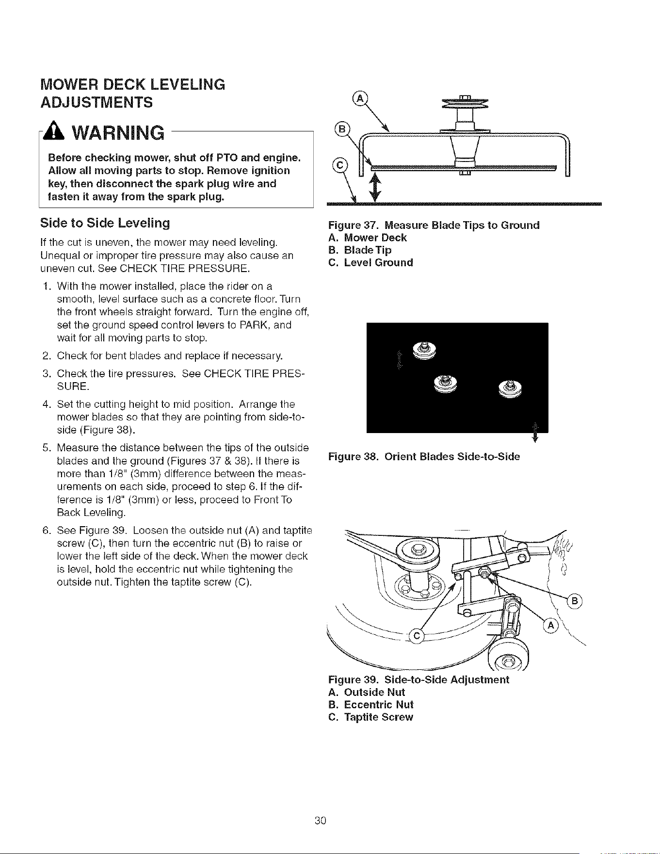
Side to Side Leveling
If the cut is uneven, the mower may need leveling.
Unequal or improper tire pressure may also cause an
uneven cut. See CHECK TIRE PRESSURE.
1. With the mower installed, place the rider on a
smooth, level surface such as a concrete floor. Turn
the front wheels straight forward. Turn the engine off,
set the ground speed control levers to PARK, and
wait for all moving parts to stop.
2. Check for bent blades and replace if necessary.
3. Check the tire pressures. See CHECK TIRE PRES-
SURE.
4. Set the cutting height to mid position. Arrange the
mower blades so that they are pointing from side-to-
side (Figure 38).
5. Measure the distance between the tips of the outside
blades and the ground (Figures 37 & 38). If there is
more than 1/8" (3mm) difference between the meas-
urements on each side, proceed to step 6. If the dif-
ference is 1/8" (3ram) or less, proceed to Front To
Back Leveling.
6. See Figure 39. Loosen the outside nut (A) and taptite
screw (C), then turn the eccentric nut (B) to raise or
lower the left side of the deck. When the mower deck
is level, hold the eccentric nut while tightening the
outside nut. Tighten the taptite screw (C).
Figure 37. Measure Blade Tips to Ground
A. Mower Deck
B, Blade Tip
C. Level Ground
Figure 38. Orient Blades Side-to-Side
\
\\
Figure 39. Side=to-Side Adjustment
A. Outside Nut
B. Eccentric Nut
C. Taptite Screw
30
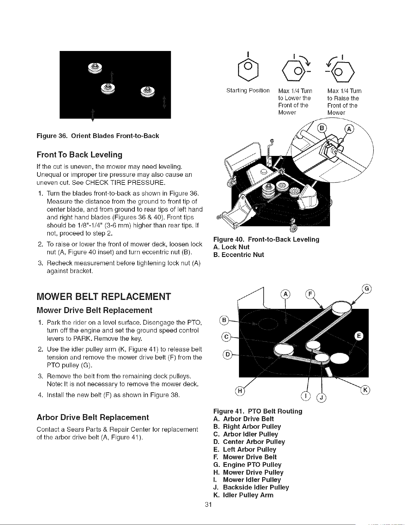
Starting Position
Max 1/4 Turn
to Lower the
Front of the
Mower
Max 1/4 Turn
to Raise the
Front of the
Mower
Figure 36. Orient Blades Front-to=Back
Front To Back Leveling
If the cut is uneven, the mower may need leveling.
Unequal or improper tire pressure may also cause an
uneven cut. See CHECK TIRE PRESSURE.
1. Turn the blades front-to-back as shown in Figure 38.
Measure the distance from the ground to front tip of
center blade, and from ground to rear tips of left hand
and right hand blades (Figures 36 & 40). Front tips
should be 1/8"-1/4" (3-8 ram) higher than rear tips. If
not, proceed to step 2.
2. To raise or lower the front o1mower deck, loosen lock
nut (A, Figure 40 inset) and turn eccentric nut (B).
3. Recheck measurement before tightening lock nut (A)
against bracket.
Figure 40. Front-to-Back Leveling
A. Lock Nut
B, Eccentric Nut
MOWER BELT REPLACEMENT
Mower Drive Belt Replacement
1. Park the rider on a level surface. Disengage the PTO,
turn off the engine and set the ground speed control
levers to PARK. Remove the key.
2. Use the idler pulley arm (K, Figure 41) to release belt
tension and remove the mower drive belt (F) from the
PTO pulley (G).
3. Remove the belt from the remaining deck pulleys.
Note: It is not necessary to remove the mower deck.
4. Install the new belt (F) as shown in Figure 38.
Arbor Drive Belt Replacement
contact a sears Parts & Repair Center for replacement
of the arbor drive belt (A, Figure 41).
Figure 41. PTO Belt Routing
A. Arbor Drive Belt
B. Right Arbor Pulley
C. Arbor Idler Pulley
D. Center Arbor Pulley
E. Left Arbor Pulley
F, Mower Drive Belt
G. Engine PTO Pulley
H. Mower Drive Pulley
I. Mower Idler Pulley
J. Backside Idler Pulley
K. Idler Pulley Arm
31
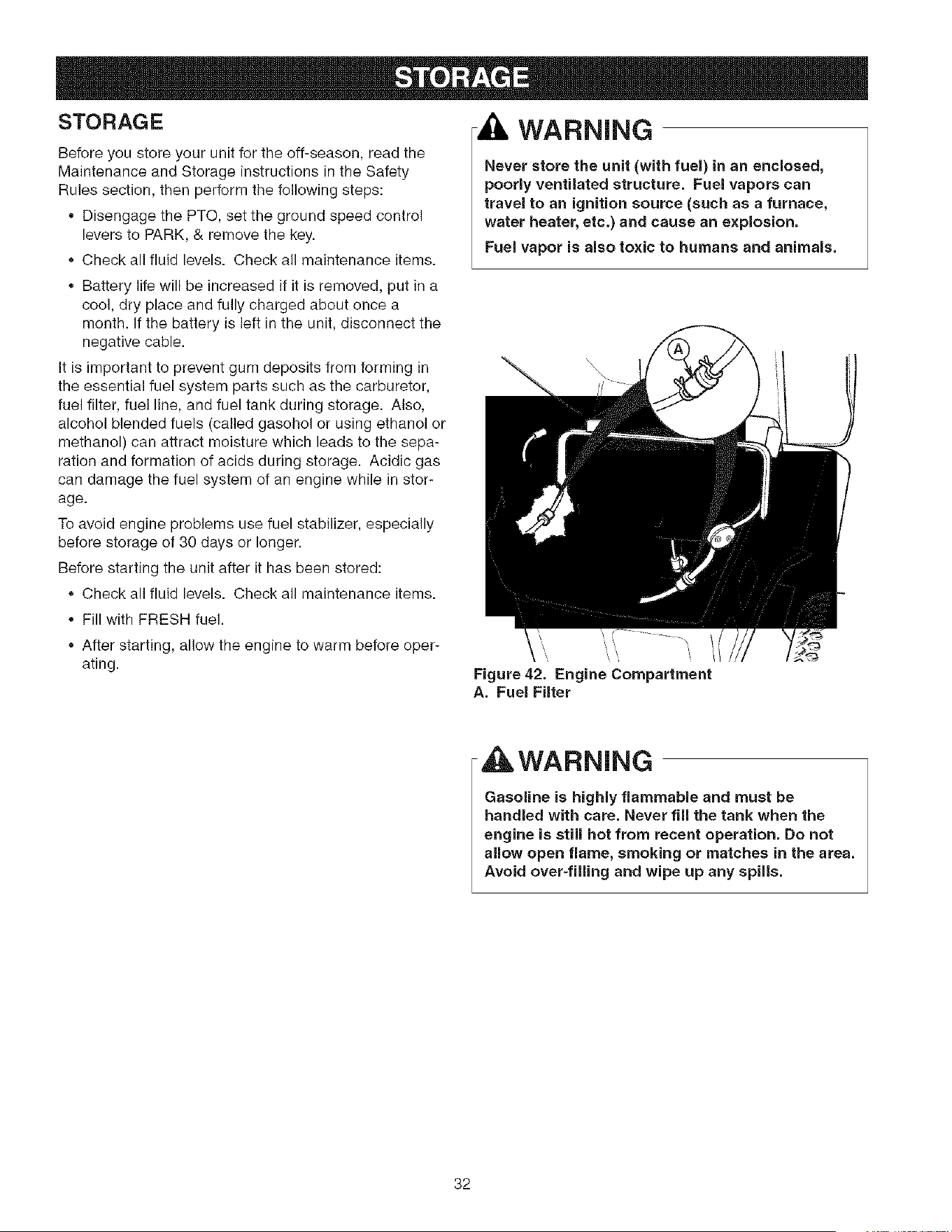
STORAGE
Before you store your unit for the off-season, read the
Maintenance and Storage instructions in the Safety
Rules section, then perform the following steps:
• Disengage the PTO, set the ground speed control
levers to PARK, & remove the key.
Check all fluid levels. Check all maintenance items.
Battery life will be increased if it is removed, put in a
cool, dry place and fully charged about once a
month. If the battery is left in the unit, disconnect the
negative cable.
It is important to prevent gum deposits from forming in
the essential fuel system parts such as the carburetor,
fuel filter, fuel line, and fuel tank during storage. Also,
alcohol blended fuels (called gasohol or using ethanol or
methanol) can attract moisture which leads to the sepa-
ration and formation of acids during storage. Acidic gas
can damage the fuel system of an engine while in stor-
age.
To avoid engine problems use fuel stabilizer, especially
before storage of 30 days or longer.
Before starting the unit after it has been stored:
Check all fluid levels. Check all maintenance items.
Fill with FRESH fuel.
After starting, allow the engine to warm before oper-
ating.
WARNING
Never store the unit (with fuel) in an enclosed,
poorly ventilated structure. Fuel vapors can
travel to an ignition source (such as a furnace,
water heater, etc.) and cause an explosion.
Fuel vapor is also toxic to humans and animals.
\
t
Figure 42. Engine Compartment
A. Fuel Filter
WARNING
Gasoline is highly flammable and must be
handled with care. Never fill the tank when the
engine is still hot from recent operation. Do not
allow open flame, smoking or matches in the area.
Avoid over-filling and wipe up any spills,
32

While normal care and regular maintenance will extend the life
of your equipment, prolonged or constant use may eventually
require that service be performed to allow it to continue operat-
ing properly. The troubleshooting guide below lists the most
common problems, their causes and remedies.
If you prefer, all of these procedures can be performed for you
by a Sears Parts & Repair Center. See the back cover for
important Sears Parts & Repair Center information.
4 ]LWARNING
To avoid serious injury, perform maintenance on
the rider or mower only when the engine is
stopped and the ground speed levers are set to
PARK.
Always remove the ignition key, disconnect the
spark plug wire and fasten it away from the plug
before beginning the maintenance, to prevent
accidental starting of the engine.
Troubleshooting the Rider
PROBLEM CAUSE REMEDY
Engine win Ground speed controls not set to PARK Set to PARK.
not turnover PTO switch in ON position. Place in OFF position.
or start.
Ground speed levers not in PARK positions. Move ground speed levers to PARK positions.
Choke not in CLOSED position. Move choke to CLOSED position.
Key not turned fully to START position. Turn key fully to START position.
Out of fuel. Allow engine to cool, then refill the fuel tank.
Engine flooded. Set choke to OPEN position when cranking engine.
Fuel is old or stale, or water in fuel. Drain fuel & replace with fresh fuel. Contact Sears
Parts & Repair.
Battery terminals require cleaning. Clean the battery terminals
Battery discharged or dead. Recharge or replace.
Spark plug(s) faulty, fouled or incorrectly Clean and gap or replace.
gapped.
Wiring loose or broken. Visually check wiring & replace broken or frayed
wires. Tighten loose connections.
Solenoid or starter motor faulty. Replace. Contact Sears Parts & Repair.
Safety interlock switch faulty. Replace. Contact Sears Parts & Repair.
Engine starts Air filter plugged Service pre-cleaner and/or replace air filter ele-
hard or runs ment.
poorly. Choke not set to CLOSED position when Set choke to CLOSED when cranking. Set choke to
cranking the engine, OR choke not set to OPEN when engine is running. A warm engine may
OPEN after engine starts, not require choking.
Spark plug faulty, fouled, or incorrectly gapped. Clean and gap or replace.
Engine Low oil level. Check/add oil as required.
knocks. Using wrong grade oil. See "Change Engine Oil" in the Maintenance
Section.
Excessive oil Engine running too hot. Clean engine cooling fins, blower screen and air
consumption, cleaner.
Using wrong weight oil. See "Change Engine Oil" in the Maintenance
Section.
Too much oil in crankcase. Drain excess oil.
Engine Dirty air filter or precleaner, or both. Service or replace as required. See Maintenance
exhaust is Section.
black. Choke set to CLOSED when engine is running. Set choke to OPEN as soon as engine starts.
33

Engine runs, but
rider will not
drive.
Rider drive belt
slips.
Parking brake
will not hold.
Rider steers or
handles poorly.
Rider tracks to
one side.
Transmission release levers in PUSH
aositions.
Drive belt slips.
Belt is broken.
Parking brake is not fully released.
Pulleys or belt greasy or oily.
Belt stretched or worn.
Parking brake is incorrectly adjusted.
Improper tire inflation.
Steering linkage is loose.
Ground speed adj. knobs not adjusted.
Move levers to DRIVE positions.
Clean or replace belt as necessary.
Replace drive belt. Contact Sears Parts & Repair.
Contact Sears Parts & Repair.
Clean as required.
Replace belt. Contact Sears Parts & Repair.
See Service & Adjustments Section.
See Maintenance Section.
Check and tighten any loose connections.
See SPEED BALANCING ADJUSTMENT
Troubleshooting the
PROBLEM
Mower cutting
height difficult to
adjust.
Mower cut is
uneven,
Mower
CAUSE
Cutting height crank threads dirty or
require lube.
Rider tires not inflated equally or properly.
Mower not leveled properly.
REMEDY
Thoroughly clean and lubricate cutting height crank
with oil.
See Maintenance Section.
See "Mower Leveling" in Service & Adjustments.
Mower cut is rough Engine speed too slow. Always set throttle to PULL when mowing.
looking,
Ground speed too fast. Decrease ground speed.
Blades are dull.
Engine stalls easily
with mower
engaged.
Excessive mower
vibration.
Mower drive belt slipping because it is oily
ar worn.
Blades not properly fastened to arbors.
Engine speed too slow.
Ground speed too fast.
Cutting height set too low.
Underside of mower deck dirty.
Blade mounting bolts are loose.
Mower blades, arbors, or pulleys are bent.
Mower blades are out of balance.
Sharpen or replace blades. See Maintenance
Section.
Clean or replace belt as necessary.
See "ChecWReplace Mower Blades" in Maintenance
Section.
Always set throttle to FULL when mowing.
Decrease Ground Speed.
Cut tall grass at maximum cutting height during first
9ass.
Remove mower deck and clean underside.
Discharge chute jamming with cut grass. Cut grass with discharge pointing toward previously
sut area.
Tighten to 45-55 ft. Ibs. (61-75 N.m.).
Check and replace as necessary.
Replace or balance blades. See Maintenance
Section.
Belt installed incorrectly. Reinstall correctly.
Mower drive belt Idler pulley spring broken or not properly Repair or replace as needed.
slips or fails to attached.
drive. Mower drive belt broken. Replace drive belt.
PTO clutch out of adjustment. Adjust PTO clutch. See Maintenance Section.
34
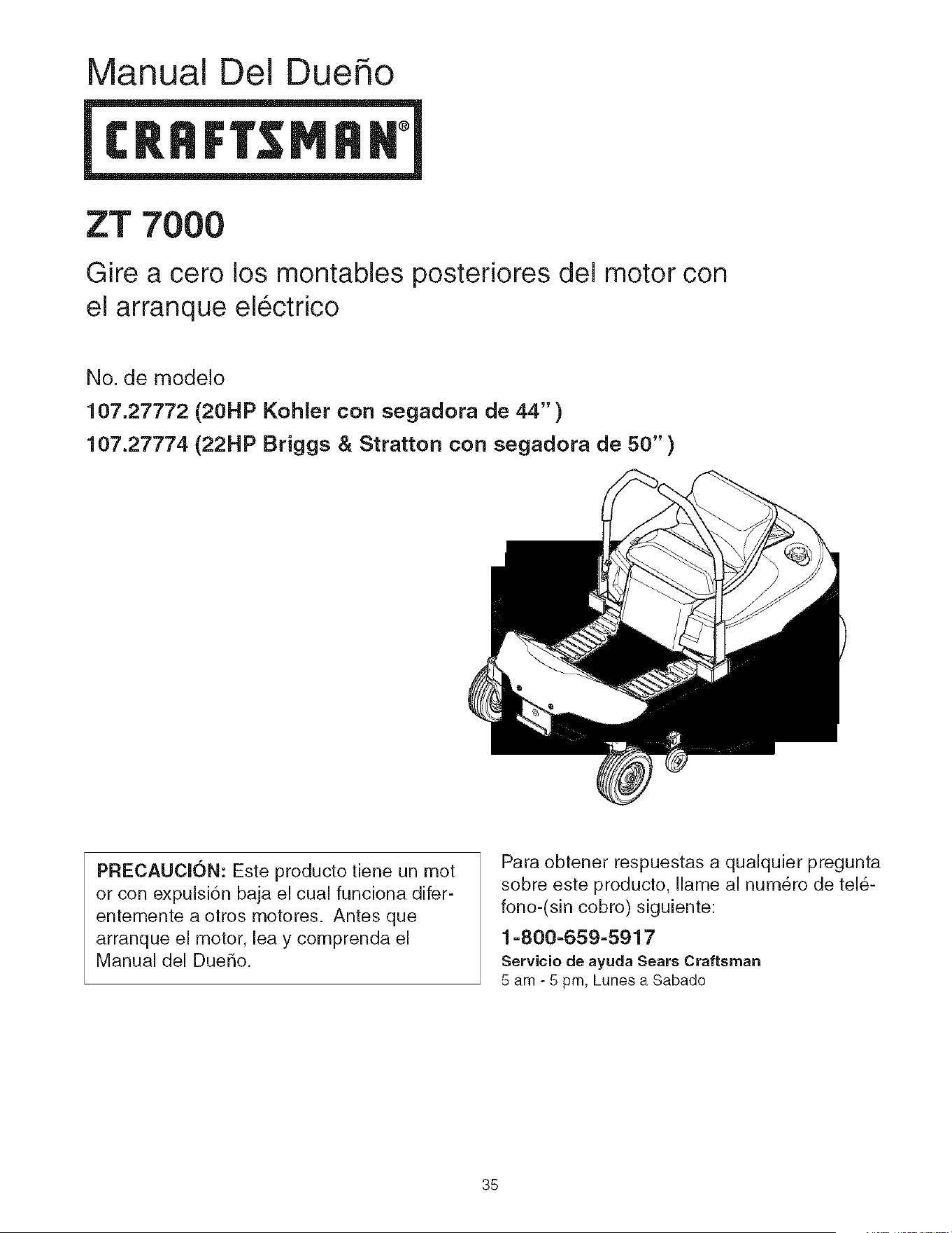
Manual Del Due o
ZT 7{
Gire a cero los montables posteriores del motor con
el arranque electrico
No. de modelo
107.27772 (20HP Kohler con segadora de 44")
107.27774 (22HP Briggs & Stratton con segadora de 50" )
PRECAUClON: Este producto tiene un mot
or con expulsi6n baja el cual funciona difer-
entemente a otros motores. Antes que
arranque el motor, lea y comprenda el
Manual del DueBo.
Para obtener respuestas a qualquier pregunta
sobre este producto, Ilame al numero de tele-
fono-(sin cobro) siguiente:
1=800-659-5917
Servicio de ayuda Sears Craftsman
5 am - 5 pm, Lunes a Sabado
35
Declaraci6n de Garantia ........................................... 36
Reglas e Informaci6n de Seguridad ........................ 37
H_meros de Identificaci6n ........................................ 41
Accesories Opcionales ............................................. 42
Contenido del Paquete de Literatura ....................... 42
Pre=Operaci6n ............................................................ 43
Operaci6n ................................................................... 44
Mantenimiento ........................................................... 51
Servicio y Ajustes ...................................................... 62
AIrnacenamiento ........................................................ 66
Diagn6stico ................................................................ 67
Partes de Refacci6n ............................................ PTS=I
Hardware y Especificaciones del Esfuerzo de
Torei6n ............................................................... PTS-39
Repare Ei Acuerdo De la
Protecci6n .................... Dentro De la Cubierta Trasera
Mantenga Los Numeros De
Phono ................................................. Cubierta Trasera
NOTA: En este manual, "izquierda" y "derecha" se refieren seg8n come se vea desde la posicidn de operacion.
= 2
GARANT[A LIMITADA DEL EQUIPO MONTABLE DE CRAFTSMAN
Per dos (2) ares a partir de la fecha de compra, sieste equipo montable de Craftsman es mantenido, lubricado y afinado
conforme alas instrucciones an el manual del propietario, Sears reparara o reemplazara sin costo alguno cualquier parte
que se encuentre defectuosa en material o mane de obra conforme a los lineamientos de la cobertura enumerada a contin-
uaci6n. Sears tambi6n proporcionar_ mane de obra gratis per las partes garantizadas que apliquen durante estos dos a_os
completes. Durante los primeros 30 dfas de compra, no habra cargos para dar servicio al producto en su domicilio per
preblemas cubiertos per esta garantia. (Vea las excepciones abajo). Para su conveniencia, el servicio de garantia A DOMI-
CILIO seguir_ estando disponible despu_s de los primeros 30 dias de compra, pero habrdt un cargo per el recorrido. Este
cargo quedar_t anulado si se Ileva el producto Craftsman en uno de los lugares autorizados de Sears. Para averiguar cuAI
es el Sears m#ts cercano a usted, le rogamos que Ilame a 1-800-MY-HOME. Esta garantia aplica s61o mientras el producto
est_ dentro de los Estados Unidos.
ESTA GARANTfA NO CUBRE:
= Arficulos consumibles que se desgastan con el use
normal, Io que incluye, entre otros las aspas, bujfas, ill-
tros de aire, bandas y filtros de aceite.
ServJcio per mantenimiento estandar, cambios de
aceite y afinaciones.
* Reemplazo o reparaci6n de Ilantas causado per pon-
chaduras de objetos externos, come clavos, pQas,
troncos cortados o vidrio.
Las reparaciones necesarias per abuse del operador,
Io qua incluye, entre otros, dahos causados per remol-
car objetos que sobrepasan las capacidades del
equipo montable, impacto contra objetos qua doblen el
bastidor o cigQe[ial o exceder la velocidad del motor.
Las reparaciones necesarias per negligencia del oper-
ador, Io que incluye, entre otros, da_os electricos y
mecanicos causados per el almacenamiento inadecua-
do, no usar el grade y la cantidad adecuada de aceite
para motor, no mantener la cubierta libre de despojos
inflamables o no mantener el equipo conforme alas
instrucciones contenidas en el manual del propietario.
La limpieza del motor (instalaci6n de combustible) o
reparaci6n causada per gasolina qua se decide esta
contaminada u oxidada (viciada). En general, el com-
bustible debe usarse en un lapse de 30 dias de su
fecha de compra.
El deterioro y desgaste normal de los acabados del
exterior ni el reemplazo de las etiquetas del producto.
Cuando el equipo montable que se usa con fines co-
merciales o de alquiler.
GARANTiA LIMITADA DE LA BATERJA
Per noventa (90) d[as a partir de la fecha de compra, la bateria incluida con este equipo montable prueba estar defectu-
osa an material o mane de obra y nuastras pruebas determinan que la bateria no retiene la carga; Sears reemplazara la
bateria sin cargos. Durante los primeros 30 dias de compra, no habrA cargos para reemplazar la bateria en su DOMIClLIO.
Despu6s de los primeros 30 dfas, para su conveniencia, el servicio de garantia A DOMIClLIO seguirA estando disponible,
pero habr_t un cargo per el recorrido. Este cargo quedar_ anulado si se Ileva el producto Craftsman en une de los lugares
autorizados de Sears. PARA AVERIGUAR CUAL ES EL SEARS MAS CERCANO A USTED, LE ROGAMOS QUE LLAME
A 1-800-MY-HOME. Esta garantia de la bateria aplica s61o mientras el producto este dentro de los Estados Unidos.
Esta garantia le otorga derechos legales especificos, pero es posible que usted tenga otros derechos, los cuales varian de
un estado a otro.
Sears, Roebuck and Co. Dept. 817WA, Hoffman Estates, IL 60179
36
Leaestasreglasdeseguridady sfgalasconcuidado.Noobedecerestasre@aspuedeocasionarla perdida
delcontrolsobrela unidad,lesionesseverasa la personao la muertedeusted,o espectadores,odaOosa la
)iedad o al equipo. Esta cubierta de la podadora es capaz de amputar manos ypies y de arrojar
_etos. El triangulo_l i en el texto denota precauciones o advertencias importantes que deben obedecerse.
OPERACJON GENERAL
1. Lea, entienda y siga todas las instrucciones en el manual y
en la unidad antes de arrancar.
2. No coloque las manos o pies cerca de las partes giratorias o
debajo de la maquina. Mantengase alejado de la abertura
de expulsion en todo momento.
3. S01o permita que un adulto responsable, que est6 familiariza-
do con las instrucciones, opere la unidad (los reglamentos
locales pueden restringir la edad del operador).
4. Retire del area objetos tales como piedras, juguetes, etc.,
que pueden ser cogidos y arrojados por las aspas.
5. AsegL]rese de que el area este libre de otra gente antes de
podar el cesped. Detenga la unidad si alguien entra en el
area.
6. Nunca Ileve pasajeros.
7. No pode el cesped en reversa a menos que sea absoluta-
mente necesario. Siempre mire hacia abajo y hacia atras
antes de echarse en reversa y mientras Io Race.
8. Nunca descargue el material directamente hacia alguien.
Evite descargar el material contra una pared u obstrucci6n.
El material puede rebotar hacia el operador. Detenga las
aspas cuando cruce por superficies cubiertas de grava.
9. No opere la maquina sin el recogedor completo de hierba,
guarda de descarga (deflector) ni otros dis )ositivos de
seguridad en su lugar y operacionales.
10. Baje la velocidad antes de dar la vuelta.
11. Nunca deje la unidad operando sin supervision. Siempre
desacople las cuchillas (PTO), ponga el freno de mano,
detenga el motor y quite las Ilaves antes de desmontar.
12. Desacople las cuchillas (PTO) cuando no este podando el
cesped. Apague el motor y espere a que todas las partes
se detengan por completo antes de limpiar la maquina,
quitar el recolector de hierba o desatascar la guarda de la
descarga.
13. Opere la maquina solo a la luz del dfa o con buena luz arti-
ficial.
14. No opere la unidad si usted esta bajo la influencia de alco-
hol o drogas.
15. Tenga cuidado con el tr_ifico si opera cerca de alguna calle.
16. Sea extremadamente cuidadoso al cargar o descargar la
unidad en un remolque o camioneta.
17. Siempre protejase los ojos cuando opere esta unidad.
18. Los datos indican que operadores, de 60 afios y mas, estan
involucrados en un gran porcentaje de lesiones asociadas
con equipos motorizados. Estos operadores deberfan eval-
uar su habilidad de operar el equipo con la suficiente
seguridad para protegerse a si mismos y a otros de
lesiones.
19. Siga las recomendaciones del fabricante respecto a los
pesos y contrapesos para Ilantas.
20. Recuerde que el operador es responsable de los acci-
dentes que ocurran a otra gente o propiedad.
21. Todos los conductores deberfan pedir y obtener instruc-
clones profesionales y practicas.
22. Siempre use zapatos cerrados y pantalones. Nunca opere
la unidad descalzo o usando sandalias.
23. Antes de su uso, siempre verifique visualmente que las
cuchillas y sus aditamentos est_n presentes, intactos y aft-
anzados. Reemplace las partes dafladas o desgastadas.
24. Desacople los accesorios antes de: cargar combustible,
retirar un accesorio, Racer ajustes (a menos de que el
ajuste pueda hacerse desde el puesto del operador).
25. Cuando la maquina esta estacionada, almacenada o se
deja sin supervision, baje los medics de corte a menos de
que use una traba mecb.nica positiva.
26. Antes de dejar el puesto del operador por cualquier razon,
acciene el freno de mano (si viene equipado con uno),
desacople las cuchillas (PTO), detenga el motor y quite la
Ilave.
27. Para reducir el peligro de incendio, mantenga la unidad libre
de cesped, hojas y aceite excesivo. No se detenga ni esta-
clone sobre hojas seoas, cesped o materiales com-
bustibles.
28. Usar u operar un motor sobre o cerca de tierras cubiertas
de bosques, matorrales o cesped es una violaciOn de la
SecciOn 4442 del Codigo de Recursos PL]blicos de
California a menos que el sistema de escape este equipa-
do con un parachispas que cumpla con las leyes locales o
estatales aplicables. Es posible que otras 4reas estatales o
federales tengan leyes similares.
TRANSPORTE Y ALIVlACENAMIENTO
1. Cuando se transporta la unidad sobre un remolque abierto,
aseg@ese de que mire hacia el frente, en direccion del
desplazamiento. Si la unidad esta mirando hacia at@s, la
fuerza del aire puede da5ar la unidad.
2. Siempre obedezca las practicas seguras para cargar com-
bustible y manejar combustible al cargar la unidad con
combustible despues del transporte o almacenamiento.
3. Nunca almacene la unidad (con combustible) en una estruc-
tura cerrada con poca ventilacion. Los vapores del com-
bustible pueden viajar a una fuente de ignicion (como un
homo, calentador de agua, etc.) y ocasionar una explosion.
Los vapores del combustible tambien son toxicos para los
humanos y animales.
4. Siempre siga las instrucciones del manual del motor respec-
to alas preparaciones de almacenamiento antes de alma-
cenar la unidad ya sea por perfodos cortos o largos.
5. Siempre siga las instrucciones del manual del motor respec-
to a los procedimientos apropiados de arranque cuando
reintegre la unidad al servicio.
6. Nunca almacene la unidad ni el contenedor de combustible
en un lugar cerrado, donde haya una llama abierfa o piloto,
como sucede con un calentador de agua. Permita que la
unidad se enfrfe antes de almacenarla.
TP 625-4103-O0-ZT-UV
37
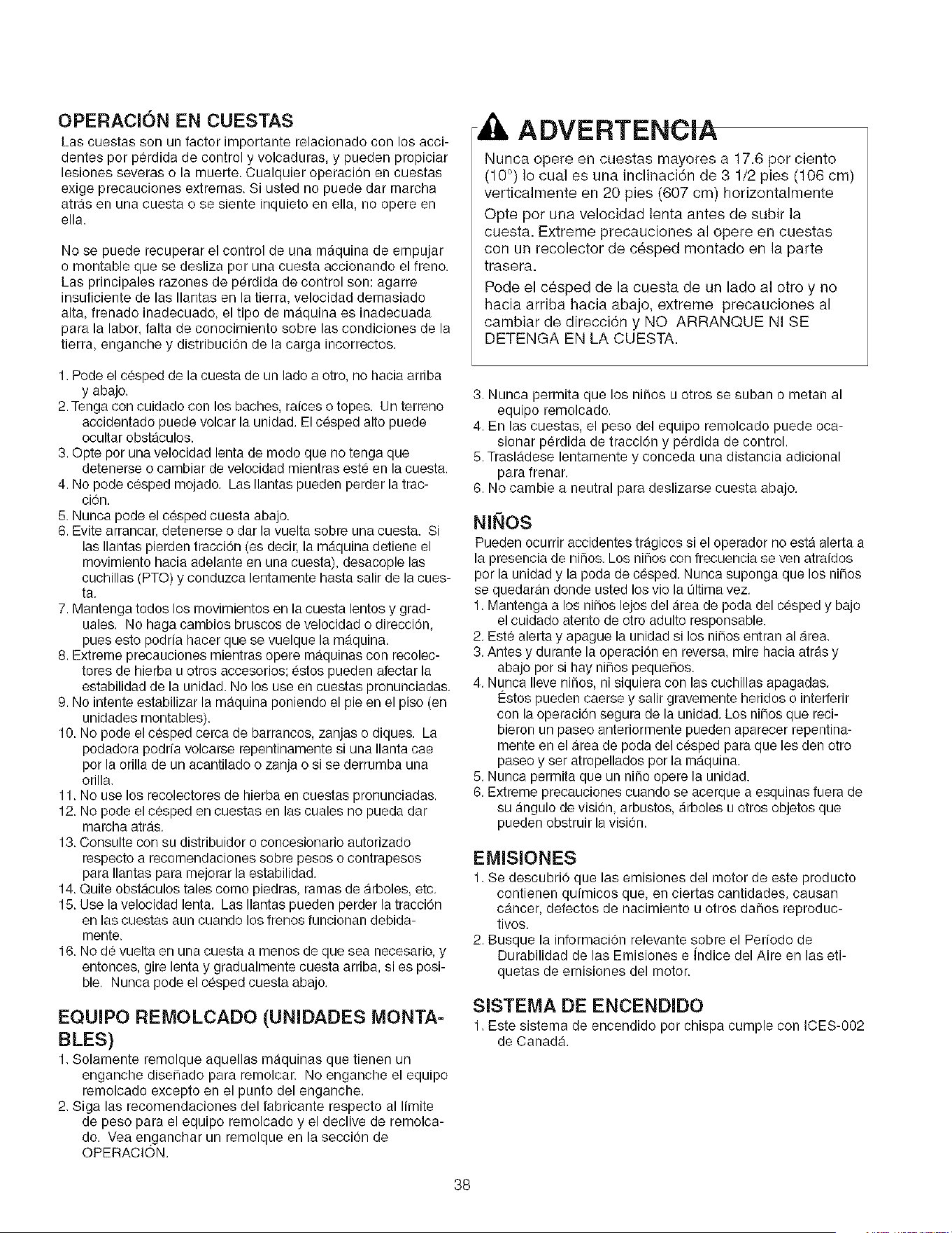
OPERACION EN CUESTAS
Las cuestas son un factor importante relacionado con los acci-
dentes por perdida de control y volcaduras, y pueden propiciar
lesiones severas o la muerte. Cualquier operacion en cuestas
exige precauciones extremas. Si usted no puede dar marcha
atras en una cuesta o se siente inquieto en ella, no opere en
ella.
No se puede recuperar el control de una maquina de empujar
o montable que se desliza por una cuesta accionando el freno.
Las principales razones de perdida de control son: agarre
insuficiente de las Ilantas en la tierrs, velocidad demssiado
alta, frenado inadecuado, el tipo de maquina es inadecuada
para la labor, falta de conocimiento sobre las condiciones de la
tierra, enganche y distribucion de la carga incorrectos.
ADVERTENOIA
Nunca opere en cuestas mayores a 17.6 per ciento
(10 °) Io cual es una inclinaciOn de 3 1/2 pies (106 cm)
verticalmente en 20 pies (607 cm) horizontalmente
Opte pot una velocidad lenta antes de subir la
cuesta. Extreme precauciones al opere en cuestas
con un recolector de c_sped montado en la parte
trasera.
Pode el cesped de la cuesta de un lado al otto y no
hacia arriba hacia abajo, extreme precauciones al
cambiar de direcciOn y NO ARRANQUE NI SE
DETENGA EN LA CUESTA.
1. Pode el c_sped de la cuesta de un lado a otro, no hacia arriba
y abajo.
2. Tenga con cuidado con los baches, raices o topes. Un terreno
accidentado puede volcar la unidad. El cesped alto puede
ocultar obstaculos.
3. ©pte por una velocidad lenta de modo que no tenga que
detenerse o cambiar de velocidad mientras este en la cuesta.
4. No pode cesped mojado. Las Ilantas pueden perder la trac-
cion.
5. Nunca pode el cesped cuesta abajo.
6. Evite arrancar, detenerse o dar la vuelta sobre una cuesta. Si
las Ilantas pierden traccion (es deck, la maquina detiene el
movimiento hacia adelante en una cuesta), desacople las
cuchillas (PTO) y conduzca lentamente hasta salir de la cues-
ta.
7. Mantenga todos los movimientos en la cuesta lentos y grad-
uales. No haga cambios bruscos de velocidad o direccion,
pues esto podria hacer que se vuelque la m_quina.
8. Extreme precauciones mientras opere maquinas con recolec-
tores de hierba u otros accesorios; estos pueden afectar la
estabilidad de la unidad. No los use en cuestas pronunciadas.
9. No intente estabilizar la maquina poniendo el pie en el piso (en
unidades montables).
16. No pode el cesped cerca de barrancos, zanjas o diques. La
podadora podrfa volcarse repentinamente si una Ilanta cae
por la orilla de un acantilado o zanja o si se derrumba una
orilla.
11. No use los recolectores de hierba en cuestas pronunciadas.
12. No pode el c_sped en cuestas en las cuales no pueda dar
marcha atras.
13. Consulte con su distribuidor o concesionario autorizado
respecto a recomendaciones sobre pesos o contrapesos
para Ilantas pars mejorar la estabilidad.
14. Quite obstaculos tales como piedras, ramas de arboles, etc.
15. Use la velocidad lenta. Las Ilantas pueden perder la tracciOn
en las cuestas aun cuando los frenos funcionan debida-
mente.
16. No de vuelta en una cuesta a menos de que sea necesario, y
entonces, gire lenta y gradualmente cuesta arriba, si es posi-
ble. Nunca pode el cesped cuesta abajo.
EQUIPO REMOLCADO (UNIDADES MONTA-
BLES)
1. Solamente remolque aquellas maquinas que tienen un
enganche disefiado para remolcar. No enganche el equipo
remolcado excepto en el punto del enganche.
2. Siga las recomendaciones del fabricante respecto al limite
de peso para el equipo remolcado y el declive de remolca-
do. Vea enganchar un remolque en la seccion de
OPERACION.
3. Nunca permita que los niOos u otros se suban o metan al
equipo remolcado.
4. En las cuestas, el peso del equipo remolcado puede oca-
sionar perdida de traccion y perdida de control.
5. Trasladese lentamente y conceda una distancia adicional
para frenar.
6. No cambie a neutral para deslizarse cuesta abajo.
NINOS
Pueden ocurrir accidentes tragicos si el operador no esta alerta a
la presencia de ni_os, Los nihos con frecuencia se yen atraidos
por la unidad y la pods de cesped, Nunca suponga que los niiios
se quedaran donde usted los viola Oltimavez.
1. Mantenga a los niiios lejos del area de poda del cesped y bajo
el cuidado atento de otro adulto responsable.
2. Est_ alerts y apague la unidad si los ni_os entran al area.
3. Antes y durante la operacion en revers& mire hacia atras y
abajo por si hay nihos peque_os.
4. Nunca Ileve nii_os, ni siquiera con las cuchillas apagadas.
I_stos pueden caerse y salir gravemente heridos o interferir
con la operacion segura de la unidad. Los ni_os que reci-
bieron un paseo anteriormente pueden aparecer repentina-
mente en el area de poda del cesped para que les den otro
paseo y ser atropellados por la maquina.
5. Nunca permita queun niilo opere la unidad.
6. Extreme precauciones cuando se acerque a esquinas fuera de
su angulo de vision, arbustos, arboles u otros objetos que
pueden obstruir la vision.
EMISIONES
1. Se descubri0 que las emisiones del motor de este producto
contienen quimicos que, en ciertas cantidades, causan
cancer, defectos de nacimiento u otros da5os reproduc-
tivos.
2. Busque la informaci0n relevante sobre el Per[odo de
Durabilidad de las Emisiones e indice del Aire en las eti-
quetas de emisiones del motor.
SISTEMA DE ENCENDIDO
1. Este sistema de encendido por chispa cumple con ICES-002
de Canada.
38
SERVIClO Y MANTENIMIENTO
Manejo Seguro de la Gasolina
1. Apague cigarros, puros, pipas y otras fuentes de ignici6n.
2. Use solo los contenedores aprobades para gasolina.
3, Nunca quite el tapon de la gasolina ni cargue combustible
con el motor encendido. Permita que el motor se enfrfe
antes de poner combustible.
4, Nunca cargue combustible para la maquina en espacios cer-
rados.
5. Nunca almacene la maquina ni el contenedor de combustible
donde haya una llama abierta, chispa o piloto, coma cerca
de un calentador de agua u otro dispositivo.
6. Nunca Ilene los contenedores dentro de un vehfculo o en la
caja de una camioneta con cobertor de platon de plastico.
Siempre coloque los contenedores en el piso, lejos de su
vehfculo antes del rellenado.
7. Retire el equipo accionado par gasolina de la camioneta o
remolque y cargue el combustible estando el equipo en el
piso. Siesto no es posible, entences cargue el combustible
en el equipo colocado en el remolque con un contenedor
portatiL en vez de usar un dispensador de gasolina.
8. Mantenga el dispensador en contacto con la orilla del tanque
de gasolina o con la abertura del contenedor en todo
momenta hasta que termine de cargar combustible. No use
un dispensador con un dispositivo de cerrado y abierto.
9. Si derrama combustible sabre la ropa> cambiese de ropa de
inmediato.
10. Nunca Ilene demasiado el tanque de gasolina. Coloque
nuevamente el tapan de la gasolina y aprietelo fijamente.
11. Extreme precauciones en el manejo de la gasolina y otros
combustibles. Son inflamables y los vapores son explo-
sivos,
12. Si se derrama combustible, no intente arrancar el motor
sine mas bien mueva la maquina lejos del area de derrame
y evite crear cualquier fuente de ignicion hasta que se
hayan disipado los vapores del combustible.
13. Vuelva a colocar fijamente las tapas del tanque de gasolina
y las tapas del contenedor del combustible.
Servieio y Mantenimiento
1. Nunca ponga en marcha la unidad en un area cerrada donde
se pueden acumular los gases del monoxido de carbono.
2. Mantenga apretadas las tuercas y pernos, en especial los
pernos de ajuste para las cuchillas, y mantenga el equipo
en buenas condiciones.
3. Nunca manipule los dispositivos de seguridad. Verifique su
operacion adecuada con regularidad y asegurese de hacer
las reparaciones necesarias si no funcionan debidamente.
4. Mantenga la unidad libre de cesped, hojas u otra acumu-
lacion de despojos. Limpie derrames de aceite o com-
bustible y quite cualquier despojo impregnado de com-
bustible. Siempre permita que su maquina se enfrfe antes
de almacenarla.
5. Detenga e inspeccione la maquina, si pega contra un objeto.
Repare, si es necesario, antes de volver a arrancar.
6. Nunca haga ajustes ni reparaciones con el motor encendido.
7. Verifique los componentes del recolector de hierba y la guar-
da de la descarga con frecuencia y reemplacelos con las
partes recomendadas par el fabricante, cuande sea nece-
sario.
8. Las cuchillas de la podadora estan afiladas. Envuelva las
cuchillas o utilice guantes, y extreme precauciones cuando
les d_ mantenimiento.
9. Verifique la operacion de los frenos con frecuencia. Ajuste y
de mantenimiento segQn se requiera.
10. Mantenga o reemplace las etiquetas de seguridad y de
instrucciones seglJn sea necesario.
11. No quite el filtro de la gasolina cuando el motor esta
caliente ya que la gasolina que se derrame se puede incen-
diar. No extienda las abrazaderas de la tuberfa del com-
bustible mas alia de Io necesario. AsegtJrese de que las
abrazaderas agarren firmemente la manguera sabre el filtro
despues de la instalacion.
12. No use gasolina que contenga METANOL, gasohol con mas
de110% de ETANOL, aditivos para gasolina ni gas blanco
porque podrfa ocasionar da_os al motor o a la instalacion
del combustible.
13. Si debe drenar el tanque de gasolina, debe hacerle al aire
libre.
14. Reemplace los silenciadores/mofles defectuosos.
15. Mantenga o reemplace las etiquetas de seguridad y de
instrucciones segt_n sea necesario.
16. Use sale las partes de repuesto autorizadas de fabrica al
reparar la unidad.
17. Siempre acate las especificaciones de fabrica respecto a
todas las disposiciones y ajustes.
18. S61o acuda a lugares autorizados de servicio si requiere de
servicio y reparaciones mayores.
19. Nunca intente hacer reparaciones mayores en esta unidad
a menos que tenga la preparacion para elle. Los proced-
imientos inadecuados de mantenimiento pueden ocasionar
peligros en la operacion, dahos al equipo y anulacion de la
garantfa del fabricante.
20. En las podadoras con cuchillas mL]ltiples, tenga cuidado ya
que hacer girar una cuchilla puede hacer que etras
cuchillas tambien giren.
21. No cambie el limitador de velocidad del motor ni acelere
demasiado el motor. ©perar el motor a una velocidad exce-
siva puede aumentar los peligros de lesiones a la persona.
22. Desacople los accesorios de conduccion, detenga el motor,
quite la Nave y desconecte el cable de la bujfa antes de:
desatorar obstrucciones en accesorios y tolvas, dar man-
tenimiento a la unidad, pegarle a un objeto o si la unidad
vibra de modo anormal. Despues de pegarle a un objeto,
inspeccione la maquina para ver si fue daaada y haga las
reparaciones antes de volver a arrancar y operar el equipo.
23. aunca coloque sus manos cerca de las partes en
movimiento, coma el ventilador de enfriamiento de la
bomba hidraulicas, cuando la unidad esta encendida. (Los
ventiladores de enfriamiento de las bombas hidraulicas nor-
malmente se encuentran arriba del transeje).
25. ADVERTENCtA: Aparato electrico almacenado. El desen-
ganche indebido de resortes puede ocasionar lesiones
graves a la persona. Los resertes deben ser quitados par
un tecnico autorizado.
39
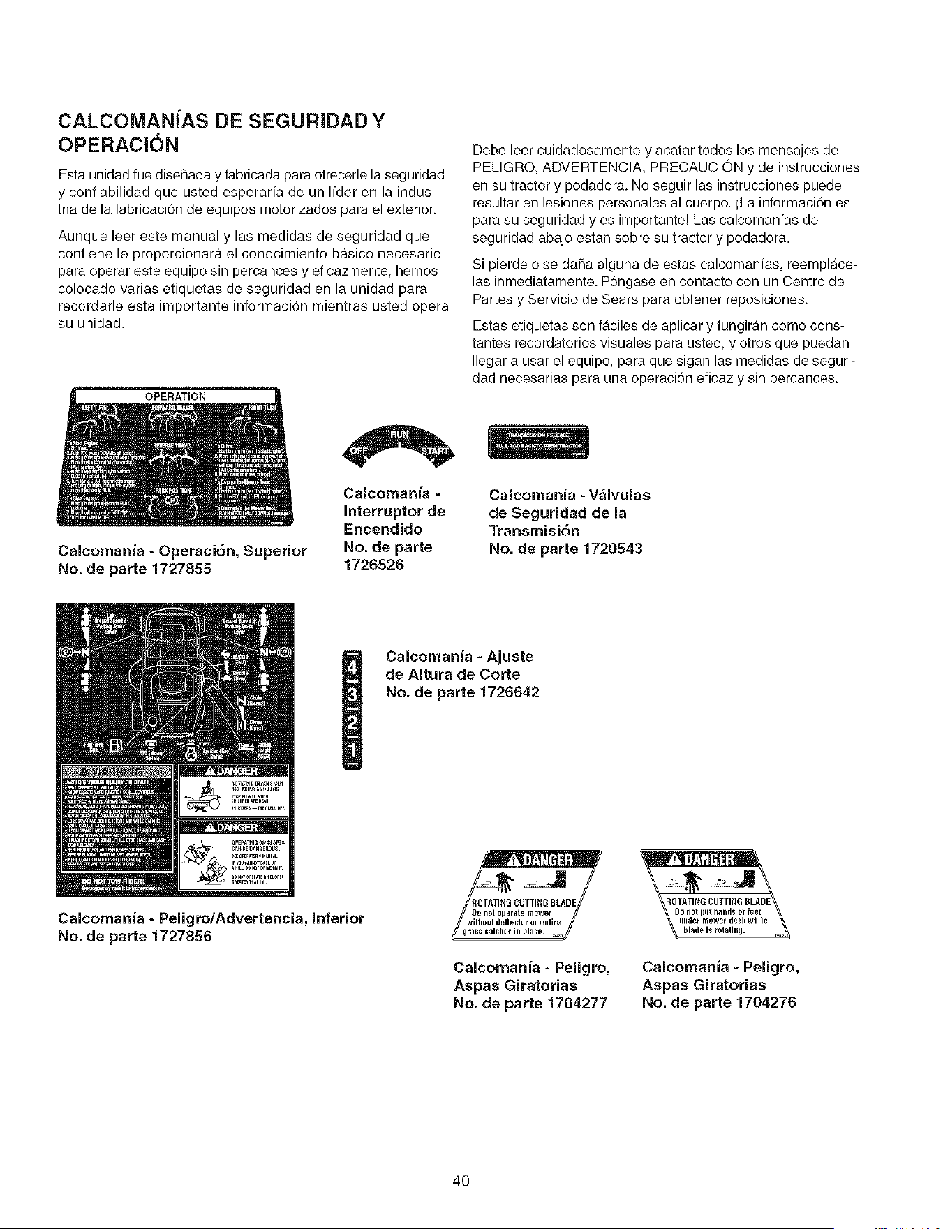
CALCOMANJAS DE SEGURiDAD Y
OPERACION
Esta unidad fue disehada y fabricada para ofrecerle la seguridad
y confiabilidad que usted esperaria de un lider en la indus-
tria de la fabricaci6n de equipos motorizados para el exterior.
Aunque leer este manual y las medidas de seguridad que
contiene le proporcionara el conocimiento basico necesario
para operar este equipo sin percances y eficazmente, hemos
colocado varias etiquetas de seguridad en la unidad para
recordarle esta importante informaciOn mientras usted opera
su unidad.
OPERATION
Calcomania - Operaci6n, Superior
No. de parte 1727855
Calcomania -
Interruptor de
Encendido
No. de parte
1726526
Debe leer cuidadosamente y acatar todos los mensajes de
PELIGRO, ADVERTENCIA, PRECAUCION y de instrucciones
en su tractor y podadora. No seguir las instrucciones puede
resultar en lesiones personales al cuerpo, iLa informaci6n es
para su seguridad yes importante! Las calcomanias de
seguridad abajo estan sobre su tractor y podadora.
Si pierde o se daha alguna de estas calcomanias, reemplAce-
las inmediatamente. P6ngase en contacto con un Centro de
Partes y Servicio de Sears para obtener reposiciones.
Estas etiquetas son faciles de aplicar y fungiran como cons-
tantes recordatorios visuales para usted, y otros que puedan
Ilegar a usar el equipo, para que sigan las medidas de seguri-
dad necesarias para una operaci6n eficaz y sin percances.
Caicomania - V_lvulas
de Seguridad de la
Transmisi6n
No. de parte 1720543
Calcomania - Ajuste
de Altura de Corte
No. de parte 1726642
Calcornania - Peligro/Advertencia, Inferior
No. de parte 1727856
Calcomania - Peligro,
Aspas Giratorias
No. de parte 1704277
ROTAT]N6 CUTTING BLADE_o rl0t put hands or feet
glider nl0wef deckwhile
blade is rotating.
Calcomania - Peligro,
Aspas Giratorias
No. de parte 1704276
40
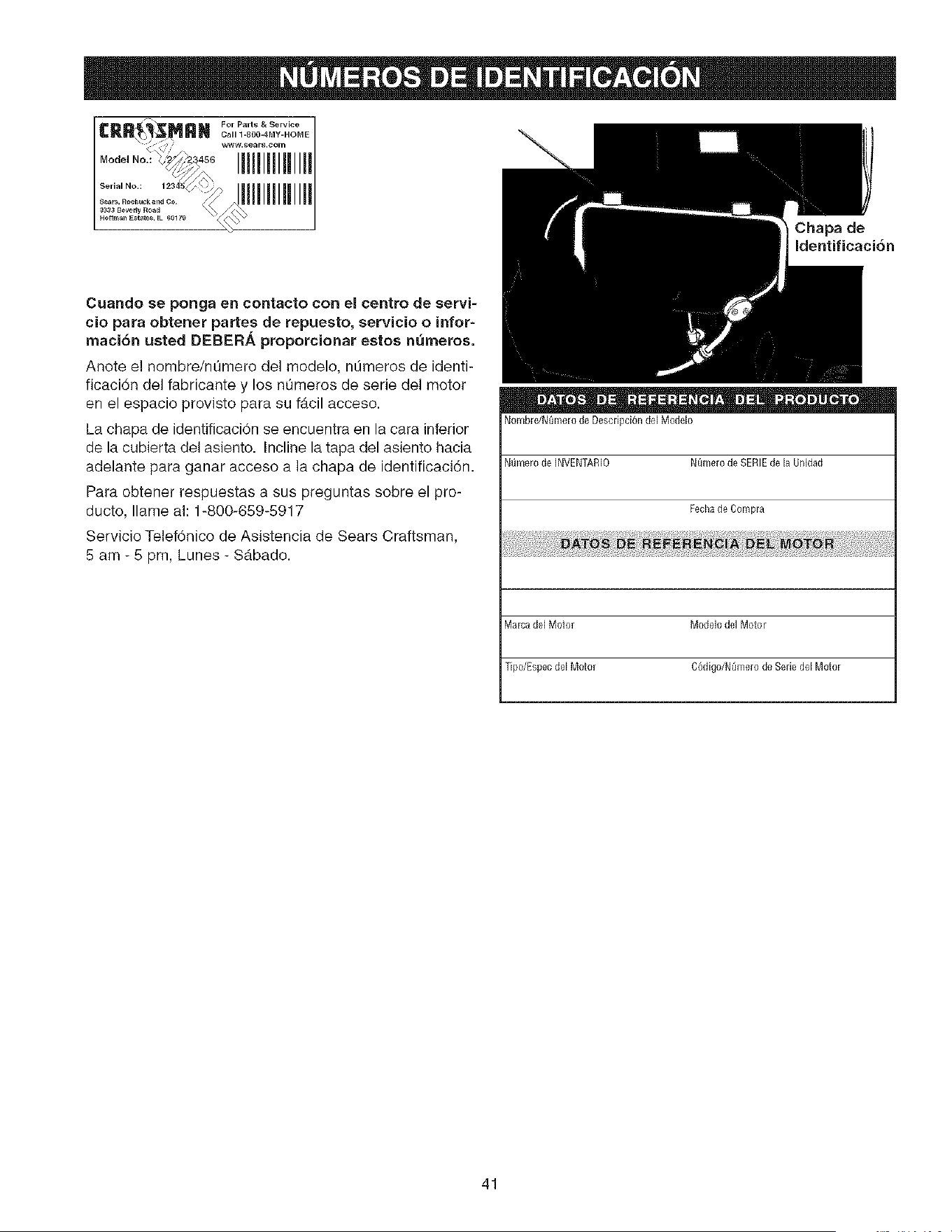
For Part8 & Service
CRR MRN
\ www _ea _ c°_
.......................JIIlllHIl[I
Chapa de
identificaci6n
Cuando se ponga en contacto con el centro de servi-
cio para obtener partes de repuesto, servicio o infor-
maci6n usted DEBER_. proporcionar estos numeros.
Anete el nombre/n0mero del modelo, nL_meros de identi-
ficaci6n del fabricante y los n0meros de serie de1motor
en el espacio provisto para su f_cil acceso.
La chapa de identificaci6n se encuentra en la cara inferior
de la cubierta del asiento. Incline la tapa del asiento hacia
adelante para ganar accese a la chapa de identificaci6n.
Para obtener respuestas a sus preguntas sobre el pro-
ducto, Ilame ah 1-800-659-5917
Servicio Telef6nico de Asistencia de Sears Craftsman,
5 am- 5 pro, Lunes- S&bado.
Nombre/N_)mero de De,scripci6n del Modelo
Nt_mero de INVENTARIO NQmerode SERIE de la Unidad
Fecha de Compra
Ma[ca de[ Moto_ Modelo del Motor
Tipo/Espec del Motor C6digo/NLime,ro de Serie dM Motor
41
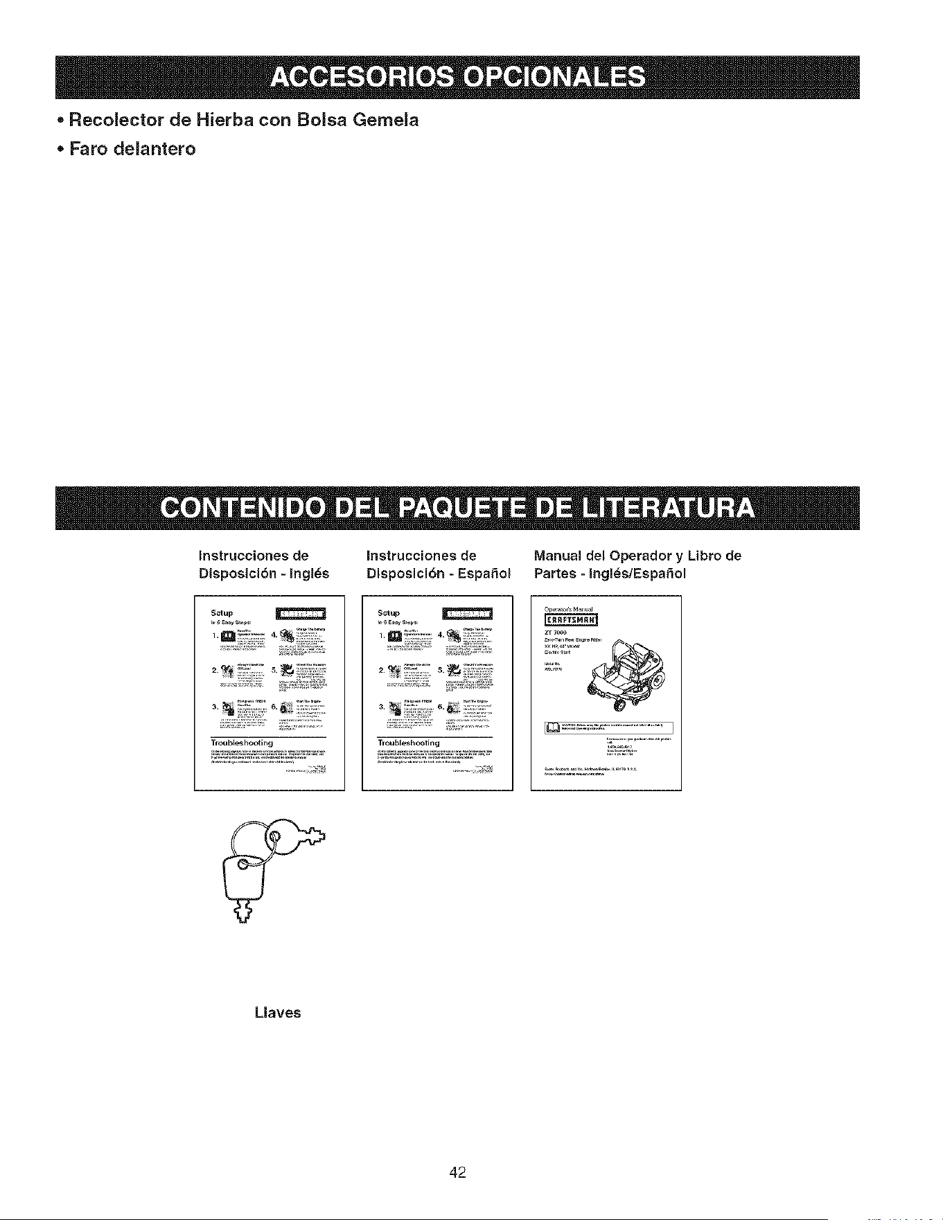
* Recolector de Hierba con Bolsa Gemela
* Faro delantero
Instrucciones de Instrucciones de Manual dei Operador y Libro de
Disposici6n - Ingl_s Disposicibn - EspaSol Partes - Ingles/EspaSol
Setup
i_!:;-7;;.............
Troubleshooting
Setup
Troubleshooting
z_ _o0o
Llaves
42
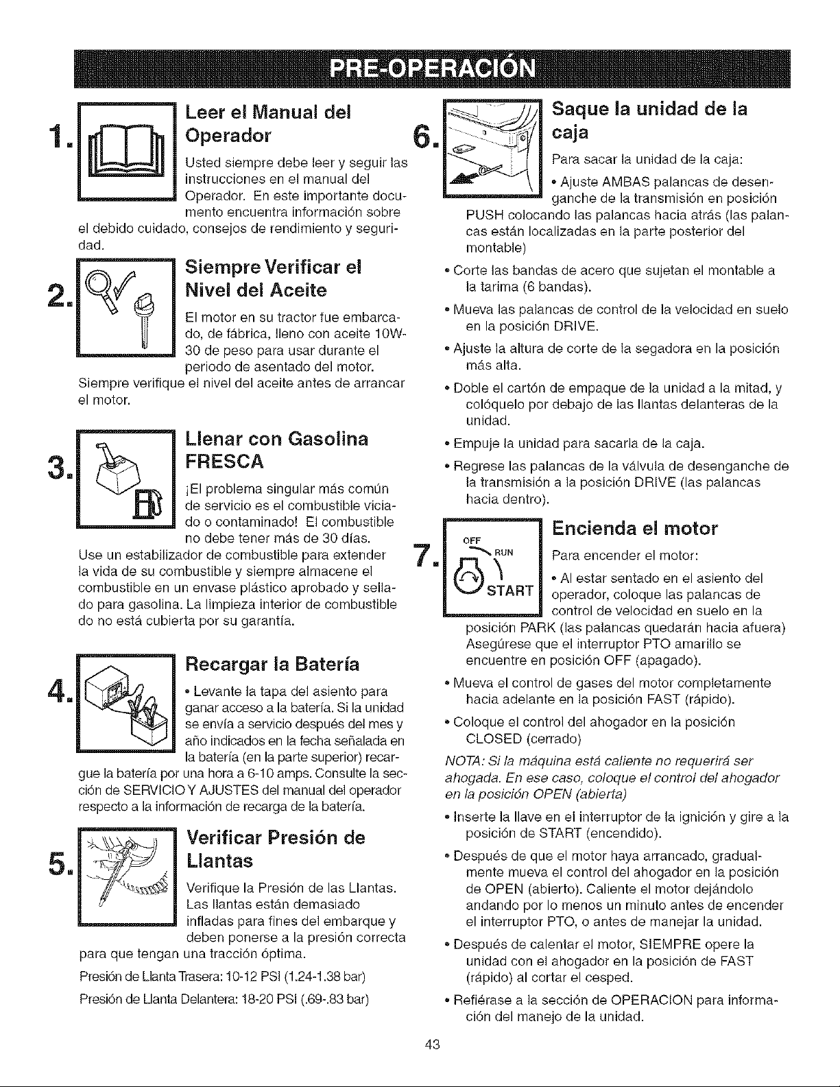
Leer el Manual dei
Operador
Usted siempre debe leer y seguir las
instrucciones en el manual del
Operador. En este importante docu-
mento encuentra informaci6n sobre
el debido cuidado, consejos de rendimiento y seguri-
dad.
Siempre Verificar el
Nivel dei Aceite
El motor en su tractor fue embarca-
do, de fabrica, Ileno con aceite 10W-
30 de peso para usar durante el
periodo de asentado de1 motor.
Siempre verifique el nivel del aceite antes de arrancar
el motor.
Llenar con Gasolina
FRESCA
iEI problema singular mas comOn
de servicio es el combustible vicia-
do o contaminado! El combustible
no debe tener m_ts de 30 dias.
Use un estabilizador de combustible para extender
la vida de su combustible y siempre almacene el
combustible en un envase plb.stico aprobado y sella-
do para gasolina. La limpieza interior de combustible
do no esta cubierta per su garantia.
Recargar la Bateria
• Levante la tapa del asiento para
ganar acceso a la bateria. Si la unidad
se envfa a servicio despu_s del mes y
a_o indicados en la fecha se_alada en
la baterfa (en la parte superior) recar-
gue la baterfa pot una hora a 6-10 amps. Consulte la sec-
ci6n de SERVlCIOY AJUSTES del manual del operador
respecto a la informaci6n de recarga de la baterfa.
m
Verificar Presi6n de
Mantas
Verifique la Presi6n de las mantas.
Las Ilantas estan demasiado
infladas para fines del embarque y
deben ponerse a la presi6n correcta
para que tengan una tracci6n 6ptima.
Presi6n de mantaTrasera: 10-12 PSi (1.24-1.38 bar)
Presi6n de manta Delantera: 18-20 PSI (.89-.83 bar)
m
m
Saque la unidad de la
caja
Para sacar la unidad de la caja:
, Ajuste AMBAS palancas de desen-
ganche de la transmisi6n en posici6n
PUSH colocando ]as palancas hacia atras (las palan-
cas estb.n Iocalizadas en ]a parte posterior del
montable)
• Corte las bandas de acero que sujetan el montable a
la tarima (6 bandas).
Mueva las palancas de control de la velocidad en suelo
en la posici6n DRIVE.
• Ajuste la altura de corte de la segadora en la posici6n
m_.s alta.
• Doble el cart6n de empaque de la unidad a la mitad, y
col6quelo por debajo de las Ilantas delanteras de la
unidad.
• Empuje la unidad para sacarla de la caja.
, Regrese las palancas de la v&lvula de desenganche de
la transmisi6n a la posici6n DRIVE (las palancas
hacia dentro).
OFF
"_ RUN
START
Encienda el motor
Para encender el motor:
• AI estar sentado en el asiento del
operador, coloque las palancas de
control de velocidad en suelo en la
posici6n PARK (]as palancas quedarb.n hacia afuera)
Asegurese que el interruptor PTO amarillo se
encuentre en posici6n OFF (apagado).
Mueva el control de gases del motor completamente
hacia adelante en la posici6n FAST (r&pido).
• Coloque el control del ahogador en la posici6n
CLOSED (cerrado)
NOTA: Si la maquina esta catiente no requerirb ser
ahogada. En ese case, co!oque el control del ahogador
en la posicidn OPEN (abierta)
Inserte la Ilave en el interruptor de la ignici6n y gire a la
posici6n de START (encendido).
Despu_s de que el motor haya arrancado, gradual-
mente mueva el control del ahogador en la posici6n
de OPEN (abierto). Caliente el motor dej_.ndolo
andando por Io menos un minuto antes de encender
el interruptor PTO, o antes de manejar la unidad.
, Despues de calentar el motor, SlEMPRE opere la
unidad con el ahogador en la posici6n de FAST
(r#.pido) al cortar el cesped.
° Refierase a la secci6n de OPERAC!ON para informa-
ci6n del manejo de la unidad.
43
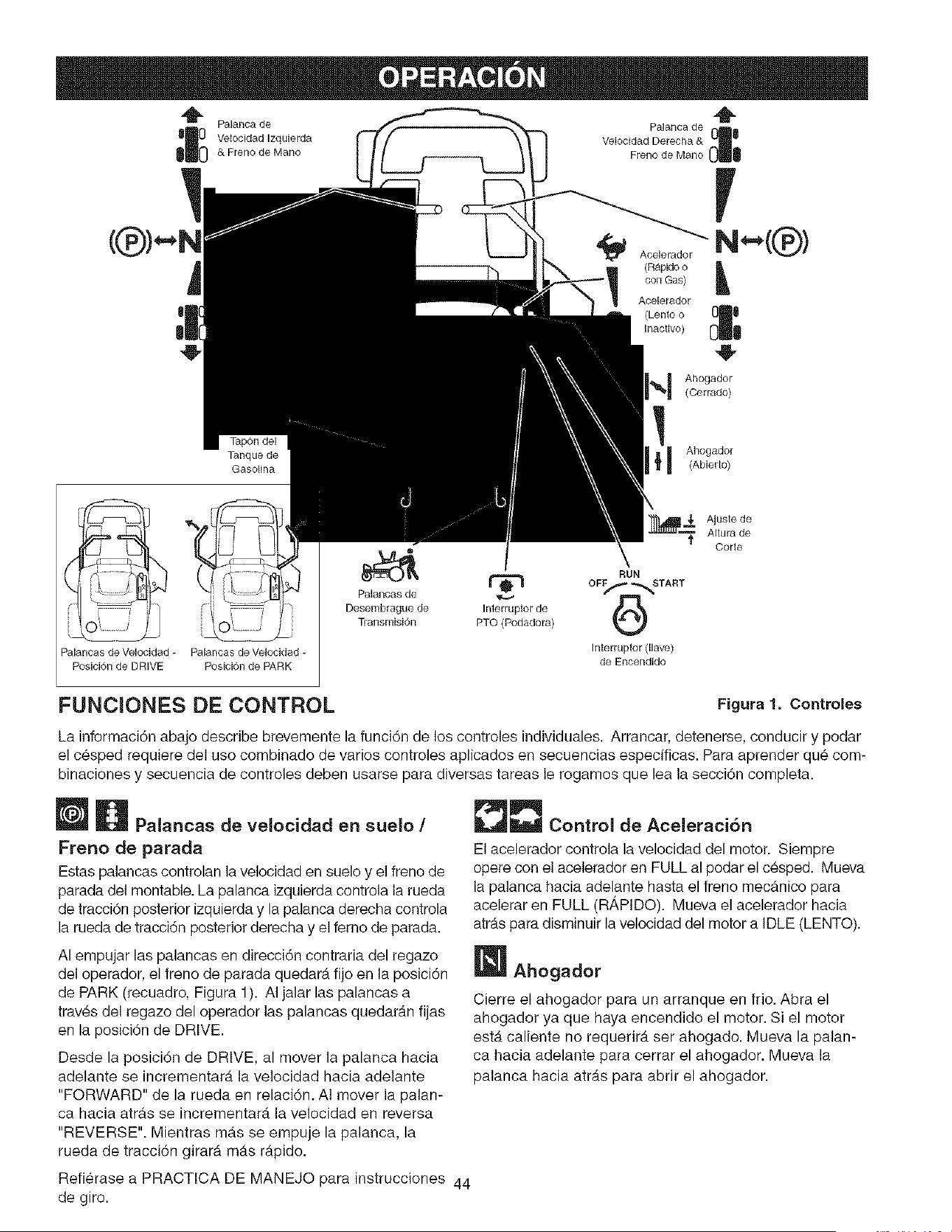
"_ Palanca de
Velocidad Izquierda
& Freno de Mano
Palanca de
Velocidad Derecha &
FreRo de Mano
Aoelerador
(Rapido o
con Gas)
Acelerador
(Lento o
Inactivo)
Tanque de
Gasolina
Ahogador
(Cerrado)
!
I Ahogador(Abierto)
! RUN
. _" _- Palancas de _
' i D_emb,_gued_ ,n_p_o_de
_)_ : , , _J Transmisi6n PTO(Podadora)
Palancas de Velocidad - Palancas de Velocidad - Interruptor (llave)
Posici6n de DRIVE Posicion de PARK de Encendido
Ajuste de
Altura de
Corte
FUNClONES DE CONTROL Figura 1. Controles
La informaci6n abajo describe brevemente la funci6n de los controles individuales. Arrancar, detenerse, conducir y podar
el c_sped requiere del uso combinado de varios controles aplicados en secuencias especificas. Para aprender qu_ com-
binaciones y secuencia de controles deben usarse para diversas tareas le rogamos que lea la secci6n completa.
Palancas de velocidad en suelo /
Freno de parada
Estas palancas controlan la velocidad en suelo y el freno de
parada del montable. La palanca izquierda controla la rueda
de tracci6n posterior izquierda y la palanca derecha controla
la rueda de tracci6n posterior derecha y el femo de parada.
AI empujar las palancas en direcci6n contraria del regazo
del operador, el freno de parada quedar_, fijo en la posici6n
de PARK (recuadro, Figura 1). AI jalar las palancas a
trav_s del regazo del operador las palancas quedarAn fijas
en la posici6n de DRIVE.
Desde la posici6n de DRIVE, al mover la palanca hacia
adelante se incrementarA la velocidad hacia adelante
"FORWARD" de la rueda en relaci6n. AI mover la palan-
ca hacia atrdts se incrementar_, la velocidad en reversa
"REVERSE". Mientras masse empuje la palanca, la
rueda de tracci6n girarA m_.s r_tpido.
Refi_rase a PRACTICA DE MANEJO para instrucciones 44
de giro.
_- Control deAceleraci6n
El acelerador controla la velocidad del motor. Siempre
opere con el acelerador en FULL al podar el c_sped. Mueva
la palanca hacia adelante hasta el freno mecanico para
acelerar en FULL (R,_PIDO). Mueva el acelerador hacia
atr_.spara disminuir la velocidad del motor a iDLE (LENTO).
W Ahogador
Cierre el ahogador para un arranque en frio. Abra el
ahogador ya que haya encendido el motor. Si el motor
est.. caliente no requerir_ ser ahogado. Mueva la palan-
ca hacia adelante para cerrar el ahogador. Mueva la
palanca hacia atr_.s para abrir el ahogador.

Ajuste de AItura de Corte de Podadora
Para ajustar la altura de corte, gire la manivela a la
derecha para subir la cubierta de la podadora y a la
izquierda para bajar la cubierta de la podadora.
[] Interruptor de Encendido
El interruptor de encendido arranca y detiene el motor;
tiene tres posiciones:
OFF (apagado) Detiene el motor y corta el
sistema electrico.
RUN (activo) Permite que el motor corra y suministra
energia al sistema electrico.
START (arrancar) Mueve el motor para que arranque.
NOTA: Nunca deje el interruptor de encendido en la posi-
cidn de RUN con et motor detenido. Esto drena la baterfa.
[] Medidor de Horas
El medidor de horas mide ]a cantidad de horas que la
Ilave Ileva en la posici6n de RUN.
NOTA: El medidor de horas registra et paso de/tiempo
cuando la Ilave esta en posicidn de RUN, aun si el motor
no esta encendido.
[] Interruptor PTO
El interruptor PTO (Eliminador de Energfa) embraga y
desembraga un embrague electrico conectado al
cig0e_al del motor. Este embrague el_ctrico conduce y
detiene la cubierta de la podadora. Para encender la
podadora, jale el interruptor hacia ARRIBA. Empuje el
interruptor hacia ABAJO para apagar la podadora. Tome
en cuenta que el operador debe estar sentado firmemente
en el asiento del conductor para que el PTO funcione.
Palancas de Desernbrague de Transmisi6n
Las palancas de desembrague de la transmisi6n desacti-
van las transmisiones para que la unidad pueda empu-
jarse manualmente. Vea EMPUJAR LA UNIDAD
MANUALMENTE respecto a ]a informaci6n operacional.
Tanque de Gasolina
Para quitar el tap6n, gire a la izquierda.
SEGURIDAD GENERAL DE OPERACION
Antes de la primera operaci6n:
• AsegL_rese de leer toda la informaci6n en las secciones
de Seguridad y Operaci6n antes de intentar operar el
tractor o la podadora.
Familiarfcese con todos los controles y c6mo detener la
unidad.
• Conduzca en un Area abierta sin podar el c_sped para
acostumbrarse a conducir la unidad.
ILADVERTENCIA
Si usted no entiende c6mo funciona un control
especifico, o no ha leido con detenimiento la secci6n
de FUNCIONES DE CONTROL, hagalo ahora.
NO intente operar el tractor sin antes
familiarizarse con la ubicaei6n y la funci6n de
TODOS los controles.
45
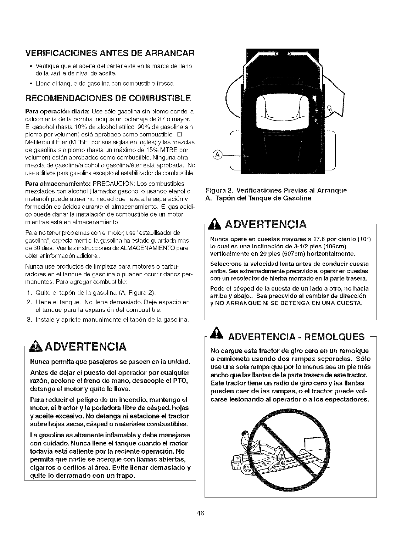
VERIFICACIONES ANTES DE ARRANCAR
- Verifique que el aceite del carter este en la marca de Ileno
de la varilla de nivel de aceite.
- Llene el tanque de gasolina con combustible fresco.
RECOMENDACIONES DE COMBUSTIBLE
Para operaci6n diaria: Use s61o gasolina sin plomo donde la
calcomania de la bomba indique un octanaje de 87 o mayor.
El gasohol (hasta 10% de alcohol etilico, g0% de gasolina sin
plomo por volumen) esta aprobado coma combustible. El
Metilerbutil Eter (MTBE, por sus siglas en ingles) y las mezclas
de gasolina sin plomo (hasta un mAximo de 15% MTBE por
volumen) esta.n aprobados como combustible. Ninguna otra
mezcla de gasolina/alcohol o gasolina/_ter est#t aprobada. No
use aditivos para gasolina excepto el estabilizador de combustible.
Para almacenamiento: PRECAUCI(_N: Los combustibles
mezclados con alcohol (llamados gasohol o usando etanol o
metanol) puede atraer humedad que Ileva a la separaci6n y
formaci6n de acidos durante el almacenamiento. El gas acfdi-
co puede daSar la instalaci6n de combustible de un motor
mientras est4 en almacenamiento.
Para no tener problemas con el motor, use "estabilisador de
gasolina", especialment si la gasolina ha estado guardada mas
de 30 dias. Yea las instrucciones de ALMACENAMIENTO para
obtener informad6n adicionaL
Nunca use productos de limpieza para motores o carbu-
radores en el tanque de gasolina o pueden ocurrir dahos per-
manentes. Para agregar combustible:
1. Quite el tap6n de la gasolina (A, Figura 2).
2. Llene el tanque. No Ilene demasiado. Deje espacio en
el tanque para la expansi6n del combustible.
3. Instale y apriete manualmente el tap6n de la gasolina.
ADVERTENCIA
Nunca permita que pasajeros se paseen en la unidad.
Antes de dejar el puesto del operador pot cualquier
raz6n, accione el freno de mano, desacople el PTO,
detenga el motor y quite la Have.
Para reducir el peligro de un incendio, mantenga el
motor, el tractor y la podadora libre de c_sped, hojas
y aceite excesivo. No detenga ni estacione el tractor
sobre hojas secas, c_sped o materiales combustibles.
La gasolina es altamente inflamable y debe manejarae
con cuidado. Nunca llene el tanque cuando el motor
todavia esta caliente pot la reciente operaci6n. No
permita que nadie se acerque con llamas abiertas,
cigarros o cerillos aJ&tea. Evite nenar demasiado y
quite Io derramado con un trapo.
Figura 2. Verificaciones Previas al Arranque
A. Tap6n del Tanque de Gasolina
ADVERTENCIA
Nunca opera en cuestas mayores a 17.6 pot ciento (10 °)
Io cual es una inclinaci6n de 3-1/2 pies (166cm)
verticaimente en 26 pies (667cm) horizontalmente.
Seleccione la velocidad lenta antes de conducir cuesta
arriba. Sea extremadamente precavido al operar en cuestas
con un recolector de hierba montado en la parte trasera.
Pode el ceaped de la cuesta de un lado a otto, no hacia
arriba y abajo_ Sea precavido al cambiar de direcci6n
y NO ARRANQUE NI SE DETENGA EN UNA CUESTA.
• ADVERTENCIA - REIVIOLQUES
No cargue este tractor de giro cero en un remolque
o camioneta usando dos Pampas separadas. S61o
use una sola tampa que pot Io menos sea un pie m_s
ancho que las llantasde la parte trasera de este tractor.
Este tractor tiene un radio de giro cero y las Ilantas
pueden caer de las rampas, o el tractor puede vol-
carae lesionando al operador o a los espectadores.
46
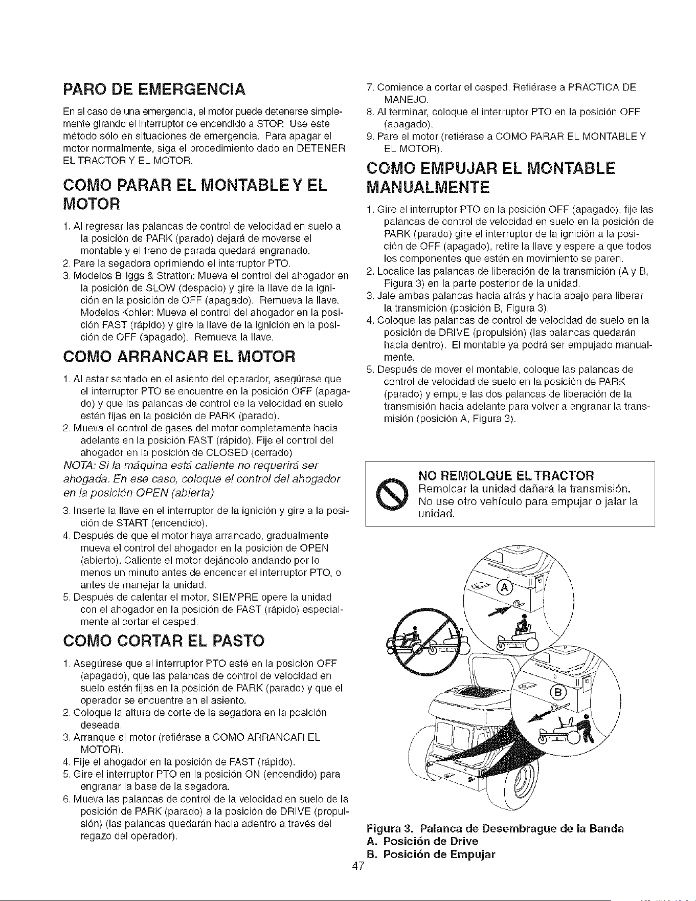
PARO DE EIVIERGENCIA
En el caso de una emergencia, el motor puede detenerse simple-
mente girando el interruptor de encendido a STOR Use este
metodo s01o en situaciones de emergencia. Para apagar el
motor normalmente, siga el procedimiento dado en DETENER
EL TRACTOR Y EL MOTOR.
COMO PARAR EL MONTABLE Y EL
MOTOR
1. AI regresar las palancas de control de velocidad en suelo a
la posicion de PARK (parado) dejara de moverse el
montable y el freno de parada quedara engranado.
2. Pare la segadora oprimiendo el interruptor PTO.
3. Modelos Briggs & Stratton: Mueva el control del ahogador en
la posicion de SLOW (despacio) y gire la Ilave de la igni-
ciOn en la posicion de OFF (apagado). Remueva la Ilave.
Modelos Kohler: Mueva el control del ahogador en la posi-
cion FAST (rapido) y gire la Ilave de la igniciOn en la posi-
cion de OFF (apagado). Remueva la Ilave.
COMO ARRANCAR EL MOTOR
1. AI estar sentado en el asiento del operador, asegurese que
el interruptor PTO se encuentre en la posicion OFF (apaga-
do) y que las palancas de control de la velocidad en suelo
esten fijas en la posicion de PARK (parado).
2. Mueva el control de gases del motor completamente hacia
adelante en la posicion FAST (rapido). Fije el control del
ahogador en la posicion de CLOSED (cerrado)
NOTA: Si la m_quina est_ caliente no requerir_ ser
ahogada. En ese caso, coloque el control del ahogador
en la posicidn OPEN (abierta)
3. Inserte la Ilave en el interruptor de la ignicion y gire a la posi-
cion de START (encendido).
4, Despues de que el motor haya arrancado, gradualmente
mueva el control del ahogador en la posicion de OPEN
(abierto). Caliente el motor dejandolo andando por Io
menos un minuto antes de encender el interruptor PTO, o
antes de manejar la unidad.
5. Despues de calentar el motor, SIEMPRE opere la unidad
con el ahogader en Is posicion de FAST (rapido) especial-
mente al cortar el cesped.
COMO CORTAR EL PASTO
1. Asegurese que el interruptor PTO este en la posicion OFF
(apagado), que las palancas de control de velocidad en
suelo est_n fijas en la posicion de PARK (parado) y que el
operador se enouentre en el asiento.
2. Coloque la altura de corte de la segadora en la posicion
deseada.
3. Arranque el motor (refierase a COMO ARRANCAR EL
MOTOR).
4. Fije el ahogador en la pesicion de FAST (rapide).
5. Gire el interruptor PTO en la posicion ON (encendido) para
engranar la base de la segadora.
6. Mueva las palancas de control de la velocidad en suelo de la
posicion de PARK (parado) a la posicion de DRIVE (propul-
sion) (las palancas quedaran hacia adentro a traves del
regazo del operador).
Figura 3. Palanca de Desembrague de la Banda
A. PosiciOn de Drive
B. PosiciOn de Empujar
7. Comience a cortar el cesped. Refierase a PRACTICA DE
MANEJO.
8. AI terminar, coloque el interruptor PTO en la posicion OFF
(apagado).
9. Pare el motor (refierase a COMO PARAR EL MONTABLE Y
EL MOTOR).
COMO EMPUJAR EL MONTABLE
MANUALMENTE
1. Gire el interruptor PTO en la posicion OFF (apagado), fije las
palancas de control de velocidad en suelo en la posicion de
PARK (parado) gire el interruptor de la ignicion a la posi-
cion de OFF (apagado), retire la Ilave y espere a que todos
los componentes que esten en movimiento se paren.
2. Localice las palancas de liberaciOn de la transmicion (A y B,
Figura 3) en la parte posterior de la unidad.
3. Jale ambas palancas hacia atras y hacia abajo para liberar
la transmicion (posicion B, Figura 3).
4. Coloque las palancas de control de velocidad de suelo en la
posicion de DRIVE (propulsion) (las palancas quedaran
hacia dentro). El montable ya podra ser empujado manual-
mente.
5. Despu_s de mover el montable, coloque las palancas de
control de velocidad de suelo en la posicion de PARK
(parado) y empuje las dos palancas de liberacion de la
transmision hacia adelante para volver a engranar la trans-
mision (posiciOn A, Figura 3).
®
NO REMOLQUE ELTRACTOR
Remolcar la unidad da_ardt ]a transmisiOn.
No use otro vehiculo para empujar o jalar la
unidad.
47
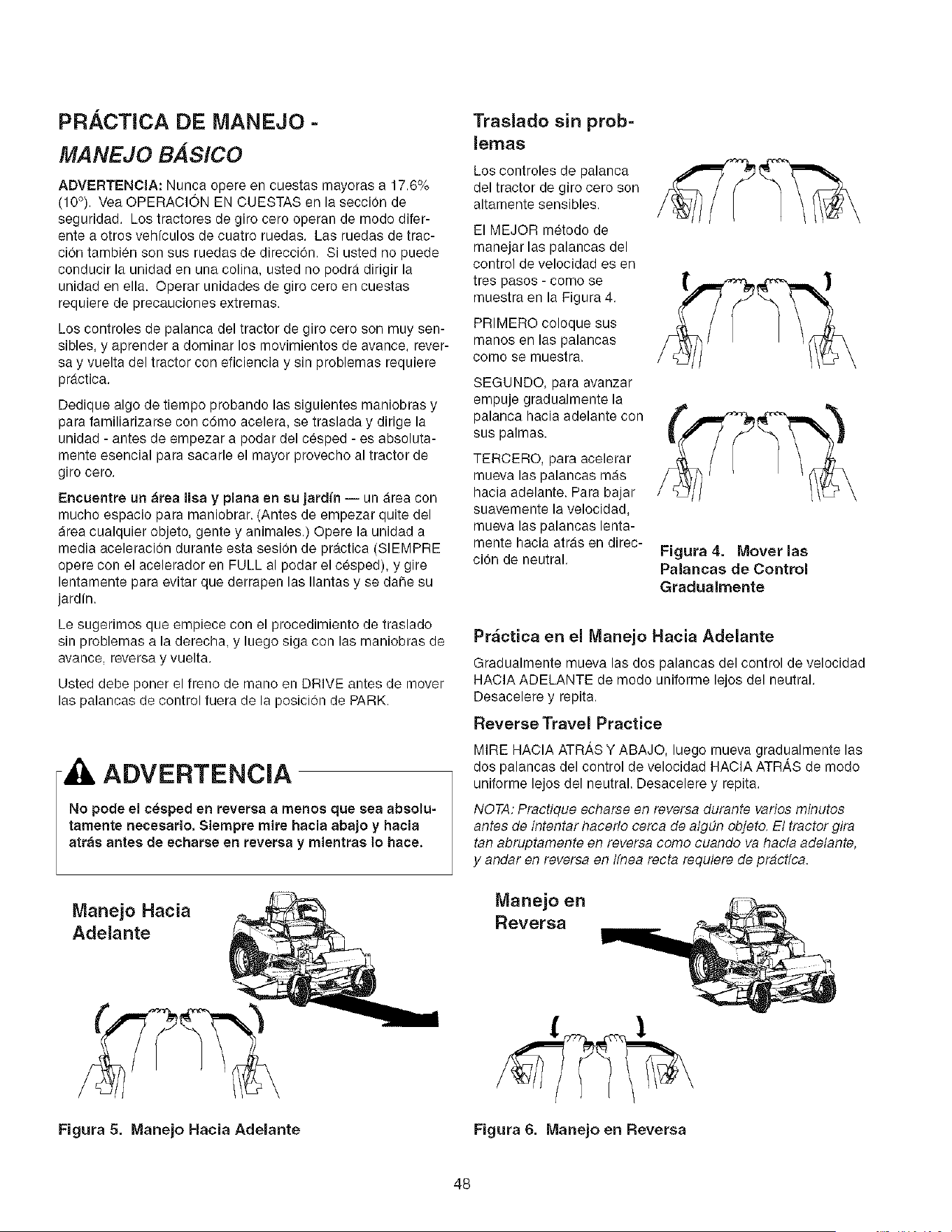
PRACTICA DE MANEJO =
MANEJO B,4S#CO
ADVERTENCIA: Nunca opere en cuestas mayoras a 17.6%
(10°), Vea OPERACION EN CUESTAS en la seccion de
seguridad. Los tractores de giro cero operan de modo difer-
ente a otros vehfculos de cuatro ruedas. Las ruedas de trac-
cion tambi_n son sus ruedas de direccion, Si usted no puede
conducir la unidad en una colin& usted no podra dirigir la
unidad en ella. Operar unidades de giro cero en cuestas
requiere de precauciones extremas.
Los controles de palanca del tractor de giro cero son muy sen-
sibles, y aprender a dominar los movimientos de avance, rever-
say vuelta del tractor con eliciencia y sin problemas requiere
practica.
Dedique algo de tiempo probando las siguientes maniobras y
para familiarizarse con c6mo acelera, se traslada y dirige la
unidad - antes de empezar a podar del c_sped - es absoluta-
mente esencial para sacarle el mayor provecho al tractor de
giro cero.
Encuentre un _rea lisa y plana en su jardfn -- un area con
mucho espacio para maniobrar. (Antes de empezar quite del
area cualquier objeto, gente y animales.) Opere la unidad a
media aceleracion durante esta sesion de practica (SIEMPRE
opere con el acelerador en FULL al podar el cesped), y gire
lentamente para evitar que derrapen las Ilantas y se dane su
jardfn.
Le sugerimos que empiece con el procedimiento de traslado
sin problemas a la derecha, y luego siga con las maniobras de
avance, reversa y vuelta.
Usted debe poner el freno de mano en DRIVE antes de mover
las palancas de control fuera de la posicion de PARK.
ADVERTENClA
No pode el ceeped en reversa a menos que sea absolu-
tamente necesario, Siempre mire hacia abajo y hacia
atras antes de echarse en reversa y mientras Io haoe.
Manejo Hacia
Adelante
Traslado sin prob-
lemas
Los controles de palanca
del tractor de giro cero son
altamente sensibles.
El MEJOR metodo de
manejar las palancas del
control de velocidad es en
tres pasos - como se
muestra en la Figura 4.
PRIMERO coloque sus
manos en las palancas
come se muestra.
SEGUNDO, para avanzar
empuje gradualmente la
palanca hacia adelante con
sus palmas.
TERCERO, para acelerar
mueva las palancas mas
hacia adelante. Para bajar
suavemente la velocidad,
mueva las palancas lenta-
mente hacia arras en direc-
cion de neutral.
Figura 4. Mover las
Palancas de Control
Gradualmente
Pr_ctica en el Manejo Hacia Adelante
Gradualmente mueva las dos palancas del control de velocidad
HACIA ADELANTE de modo uniforme lejos del neutral.
Desacelere y repita.
Reverse Travel Practice
MIRE HACIA ATRAS Y ABAJO, luego mueva gradualmente las
dos palancas del control de velocidad HACIA ATRAS de mode
unilorme lejos del neutral. Desacelere y repita.
NOTA: Practique echarse en reversa durante varies minutes
antes de intentar hacerlo cerca de algdn objeto, El tractor gira
tan abruptamente en reversa come cuando va hac/a adelante,
y andar en reversa en Ifnea recta requiere de practica.
Manejo en
Reversa
Figura 5. Manejo Hacia Adelante Figura 6. Manejo en Reversa
48
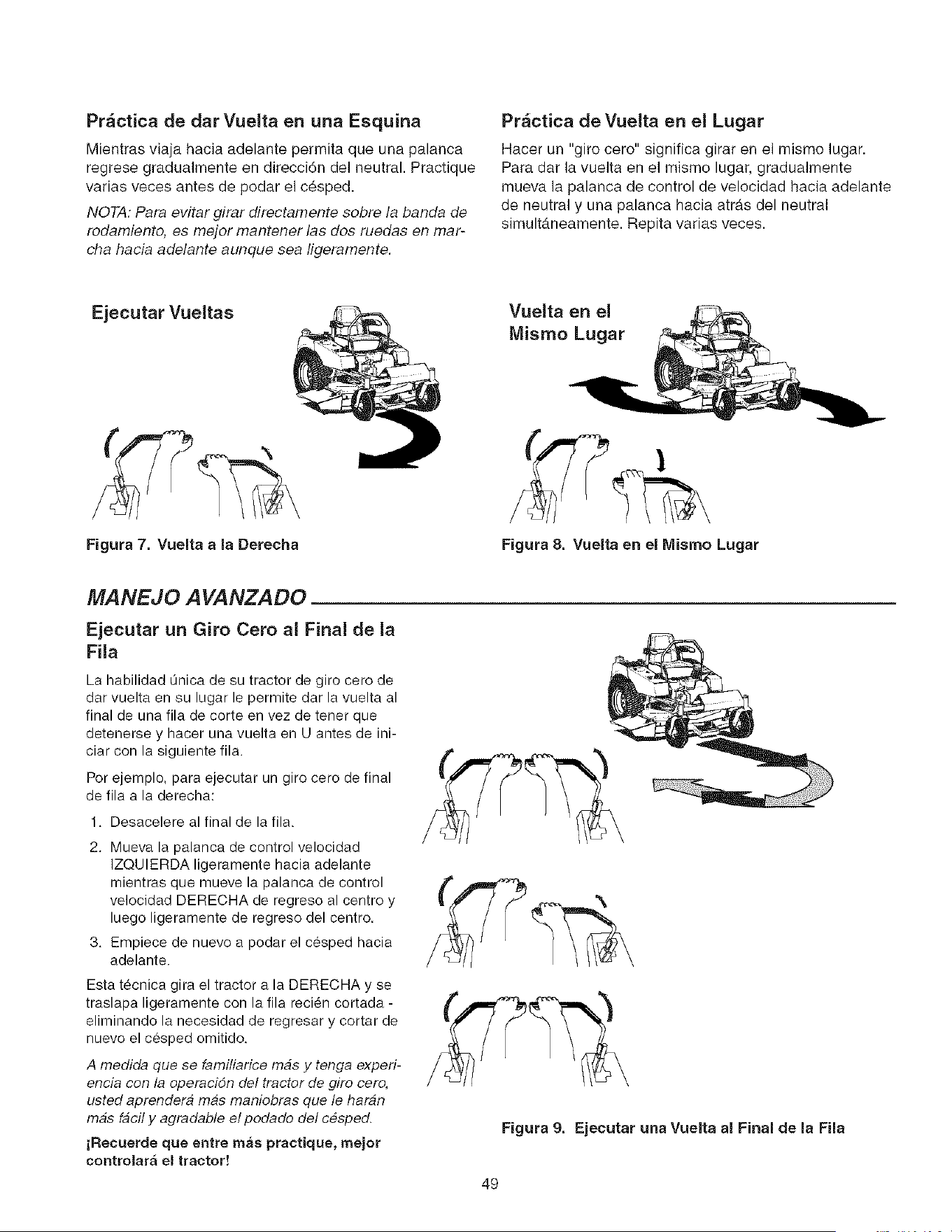
Pr_ctica de dar Vuelta en una Esquina
Mientras viaja hacia adelante permita que una palanca
regrese gradualmente en direcci6n del neutral. Practique
varias veces antes de podar el cesped.
NOTA: Para evitar girar directamente sobre la banda de
rodamiento, es mejor mantener las dos ruedas en mar-
cha hacia adelante aunque sea tigeramente.
Pr_ctica de Vuelta en el Lugar
Hacer un "giro cero" significa girar en el misme lugar.
Para dar la vuelta en el mismo lugar, gradualmente
mueva la palanca de control de velecidad hacia adelante
de neutral y una palanca hacia atr&s del neutral
simult4neamente. Repita varias veces.
Ejecutar Vueltas
Vuelta en el
Mismo Lugar
Figura 7. Vuelta a la Derecha Figura 8. Vuelta en el Mismo Lugar
MANEJO A VANZADO
Ejecutar un Giro Cero al Final de la
Fila
La habilidad Qnica de su tractor de giro cero de
dar vuelta en su lugar le permite dar la vuelta al
final de una fila de corte en vez de tener que
detenerse y hacer una vuelta en U antes de ini-
ciar con la siguiente fila.
Por ejemplo, para ejecutar un giro cero de final
de ilia a la derecha:
1. Desacelere al final de la ilia.
2. Mueva la palanca de control velocidad
IZQUIERDA ligeramente hacia adelante
mientras qua mueve la palanca de control
velocidad DERECHA de regreso al centro y
luego ligeramente de regreso del centro.
3. Empiece de nuevo a podar el c6sped hacia
adelante.
Esta t_cnica gira el tractor a la DERECHA y se
traslapa ligeramente con la fila reci_n cortada -
eliminando la necesidad de regresar y cortar de
nuevo el cesped omitido.
A medida que se familiarice mbs y tenga experi-
encia con la operacidn del tractor de giro cero,
usted aprendera mas maniobras que le haran
mas fbcil y agradable el podado del c#sped.
jRecuerde que entre mas practique, mejor
controlar_ el tractor!
Figura 9. Ejecutar una Vuelta al Final de la Fila
49
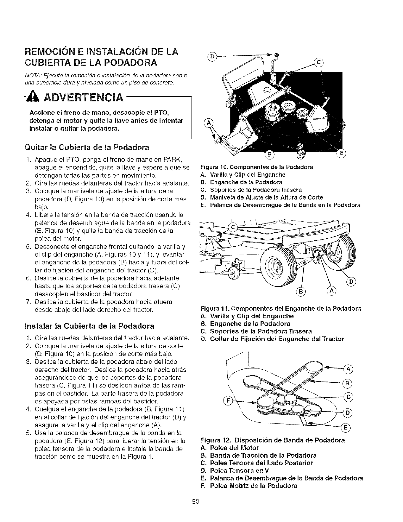
REIVIOCION E INSTALACION DE LA
CUBIERTA DE LA PODADORA
NOTA: Ejecute la remocidn e instalacidn de la podadora sobre
una superflcie dura y nivelada como un piso de concreto.
ADVERTENCIA
Accione el freno de mano, desacople el PTO,
detenga el motor y quite la Ilave antes de intentar
instalar o quitar la podadora.
Quitar la Cubierta de ]a Podadora
1. Apague el PTO, ponga e] freno de mano en PARK,
apague el encendido, quite la Ilave y espere a que se
detengan todas las partes en movimiento.
2. Gire las ruedas delanteras del tractor hacia adelante.
3. Co]oque la manivela de ajuste de la altura de la
podadora (D, Figura 10) en la posici6n de corte m_s
bajo.
4. Libere ]a tensi6n en la banda de tracci6n usando la
palanca de desembrague de la banda en la podadora
(E, Figura 10) y quite ]a banda de tracci6n de ]a
polea del motor.
5. Desconecte el enganche frontal quitando la varil]a y
el clip del enganche (A, Figuras 10 y 11), y levantar
el enganche de ]a podadora (B) hacia y fuera del col-
lar de fijaci6n del enganche del tractor (D).
6. Deslice la cubierta de la podadora hacia adelante
hasta que los soportes de la podadora trasera (C)
desacoplen el bastidor de] tractor.
7. Deslice la cubierta de la podadora hacia afuera
desde abajo de] lado derecho del tractor.
Instalar la Cubierta de la Podadora
1. Gire las ruedas delanteras del tractor hacia adelante.
2. Coloque la manivela de ajuste de ]a altura de corte
(D, Figura 10) en la posici6n de corte m_,s bajo.
3. Deslice la cubierta de la podadora abajo del lado
derecho del tractor. Des]ice la podadora hacia atr,_s
asegur_ndose de que los soportes de la podadora
trasera (C, Figura 11) se deslicen arriba de las ram-
pas en e] bastidor. La parte trasera de la podadora
es apoyada pot estas rampas del bastidor.
4. Cuelgue e] enganche de la podadora (B, Figura 11)
en el collar de fijaci6n del enganche del tractor (D) y
asegure la varilla y el clip del enganche (A).
5. Use la palanca de desembrague de la banda en ]a
podadora (E, Figura 12) para liberar la tensi6n en ]a
po]ea tensora de la podadora e instale la banda de
tracci6n como se muestra en la Figura 1.
Figura 10. Componentes de la Podadora
A. Vadlla y Clip del Enganche
B. Enganche de la Podadora
C. Soportes de la PodadoraTrasera
D, Manivela de Ajuste de la Altura de Corte
E. Palanca de Desembrague de la Banda en la Podadora
Figura 11. Componentes del Enganche de ia Podadora
A. Varilla y Clip del Enganche
B, Enganche de la Podadora
C. Soportes de la Podadora Trasera
D. Collar de Fijaci6n del Enganche del Tractor
Figura 12. Disposici6n de Banda de Podadora
A. Polea del Motor
B. Banda deTracci6n de la Podadora
C. Polea Tensora del Lado Posterior
D. Polea Tensora en V
E. Palanca de Desembrague de la Banda de Podadora
F, Polea Motriz de la Podadora
5O
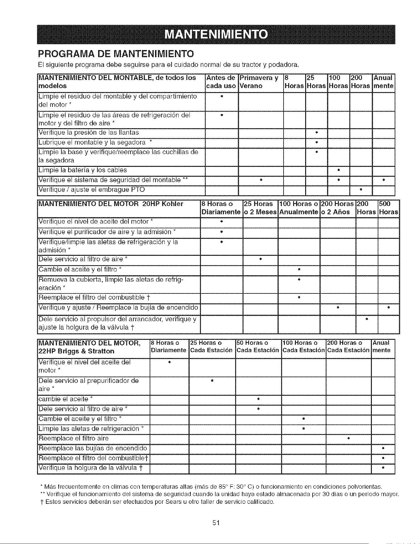
JL
PROGRAMA DE IVIANTENIMIENTO
El siguiente programa debe seguirse para el cuidado normal de su tractor y podadora.
_ANTENIMIENTO DEL MONTABLE, de todos los Antes de Primavera y 8 25 100 200 Anual
rnodeloe cada ueo Verano aoras Horas Horas Horas mente
_impie el residuo del montable y del compartimiento +
Jel motor *
_impie el residuo de las areas de refrigeraci6n del +
+notor y del filtro de aire *
7erifique la presi6n de las Ilantas
_ubrique el montable y la segadora *
+impie la base y verifique/reemplace las cuchillas de +
a segadora
_impie la baterfa y los cables
7erifique el sistema de seguddad del montable ** • •
7erifique / ajuste el embrague PTO *
_ANTENIMIENTO DEL MOTOR 20HP Kohler 8 Horas o 25 Horas 100 Horas o 200 Horas 200 500
Diariamente _ 2 Meses Anualmente _ 2 A_os Horas Horas
7erifique el nivel de aceite del motor *
7erifique el purificador de aire y la admisi6n * +
Verifique/limpie las aletas de refrigeraci6n y la °
_dmisi6n *
Dele servicio al filtro de aire *
.Sambie el aceite y el filtro * °
Remueva la cubierta, limpie las aletas de refrig- +
_=raci6n*
Reemplace el filtro del combustible 1- +
7erifique y ajuste / Reemplace la bujia de encendido • +
Dele servicio al propulsor del arrancador, verifique y +
_juste la holgura de la v_lvula 1
k_ANTENIMIENTO DEL MOTOR, 8 Horas o 25 Horas o 50 Horas o 100 Horas e 200Horas o Cnual
22HP Briggs & Stratton Diariamente Cada Estaci6n Cada Estaci6n Cada Estaci6n 3ada Estaci6n "neete
7erifique el nivel del aceite del °
"iqotor *
Dele servicio al prepurificador de +
_ire *
_'ambie el aceite * +
:}ele servicio al filtro de aire * +
3ambie el aceite y el filtro * +
_impie las aletas de refrigeraci6n * +
Reemplace el filtro aire °
Reemplace las bujfas de encendido °
Reemplace el filtro del combustible1, °
7erifique la holgura de la v_tlvula 1- +
* Mas frecuentemente en climas con temperaturas altas (mas de 85 ° F: 30 ° C) o funcionamiento en condiciones polvorientas.
** Verifique el funcionamiento del sistema de seguridad cuando la unidad haya estado almacenada por 30 dias o un periodo mayor,
1 Estos servicios deberan ser efectuados por Sears u otro taller de servicio calificado.
51
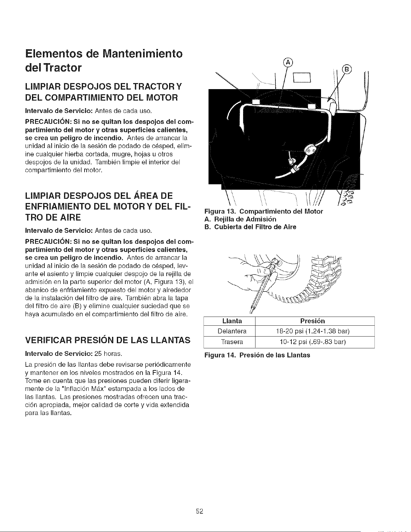
Elementos de lVlantenimiento
del Tractor
MMPIAR DESPOJOS DEL TRACTOR Y
DEL COMPARTIMIENTO DEL MOTOR
Intervalo de Servicio: Antes de cada use.
PRECAUCION: Si no se quitan los despojos del com-
partimiento dei motor y otras superficies calientes,
se crea un peligro de incendio. Antes de arrancar la
unidad al inicie de la sesi6n de pedade de c_sped, elim-
ine cualquier hierba cortada, mugre, hojas u otros
despejes de la unidad. Tambi6n limpie el interior del
compartimiento del motor.
LIMPIAR DESPOJOS DEL AREA DE
ENFRIAMIENTO DEL MOTOR Y DEL FIL-
TRO DE AIRE
Intervalo de Servicio: Antes de cada use.
PRECAUClON: Si no se quitan los despojos del com-
partimiento del motor y otras superficies calientes,
se crea un peligro de incendio. Antes de arrancar la
unidad al inicio de la sesi6n de pedade de c6sped, lev-
ante el asiento y limpie cualquier despeje de la rejilla de
admisi6n en la parte superior del motor (A, Figura 13), el
abanico de enfriamiento expuesto del motor y alrededor
de la instalaci6n del filtro de aire. Tambi_n abra la tapa
del filtro de aire (B) y elimine cualquier suciedad que se
haya acumulado en el compartimiente del filtro de aire.
VERIFICAR PRESION DE LAS LLANTAS
Intervalo de Servicio: 25 horas.
La presi6n de las Ilantas debe revisarse peri6dicamente
y mantener en los niveles mostrados en la Figura 14.
Tome en cuenta que las presiones pueden diferir ]igera-
mente de la "lnflaci6n M_.x" estampada a los lades de
las Ilantas. Las presiones mostradas ofrecen una trac-
ci6n apropiada, mejor calidad de corte y vida extendida
para las Ilantas.
Figura 13. Compartimiento del Motor
A. Rejilla de Admisi6n
B. Cubierta del Filtro de Aire
Llanta Presi6n
Delantera 18-20 psi (1.24-1.38 bar)
Trasera 10-12 psi (.69-.83 bar)
Figura 14. Presi6n de las Mantas
52
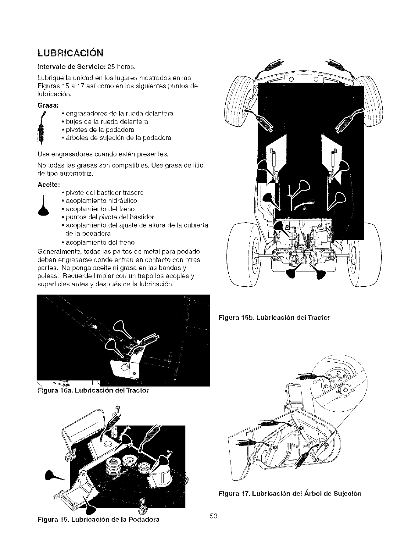
LUBRICACION
Intervalo de Servicio: 25 horas.
Lubrique la unidad en los lugares mostrados en las
Figuras 15 a 17 asf como en los siguientes puntos de
lubricaci6n.
Grasa:
engrasadores de la rueda delantera
bujes de la rueda delantera
pivotes de la podadora
• Arboles de sujeci6n de la podadora
Use engrasadores cuande est_n presentes.
No todas las grasas son compatibles. Use grasa de litio
de tipo automotriz.
Aceite:
pivote del bastidor trasero
_1_ _acoplamiento hidraulico
acoplamiento del freno
* puntos del pivote del bastidor
acoplamiento del ajuste de altura de la cubierta
de la podadora
acoplamiento del freno
Generalmente, todas las partes de metal para podado
deben engrasarse deride entran en contacto con otras
partes. No ponga aceite ni grasa en las bandas y
poleas. Recuerde limpiar con un trapo los acoples y
superficies antes y despues de la lubricaci6n.
\..
Figura 16a. Lubricaci6n del Tractor
Figura 16b. Lubricaci6n del Tractor
Figura 17. Lubricaci6n del i_rbol de Sujeci6n
Figura 15. Lubricaci6n de la Podadora 53
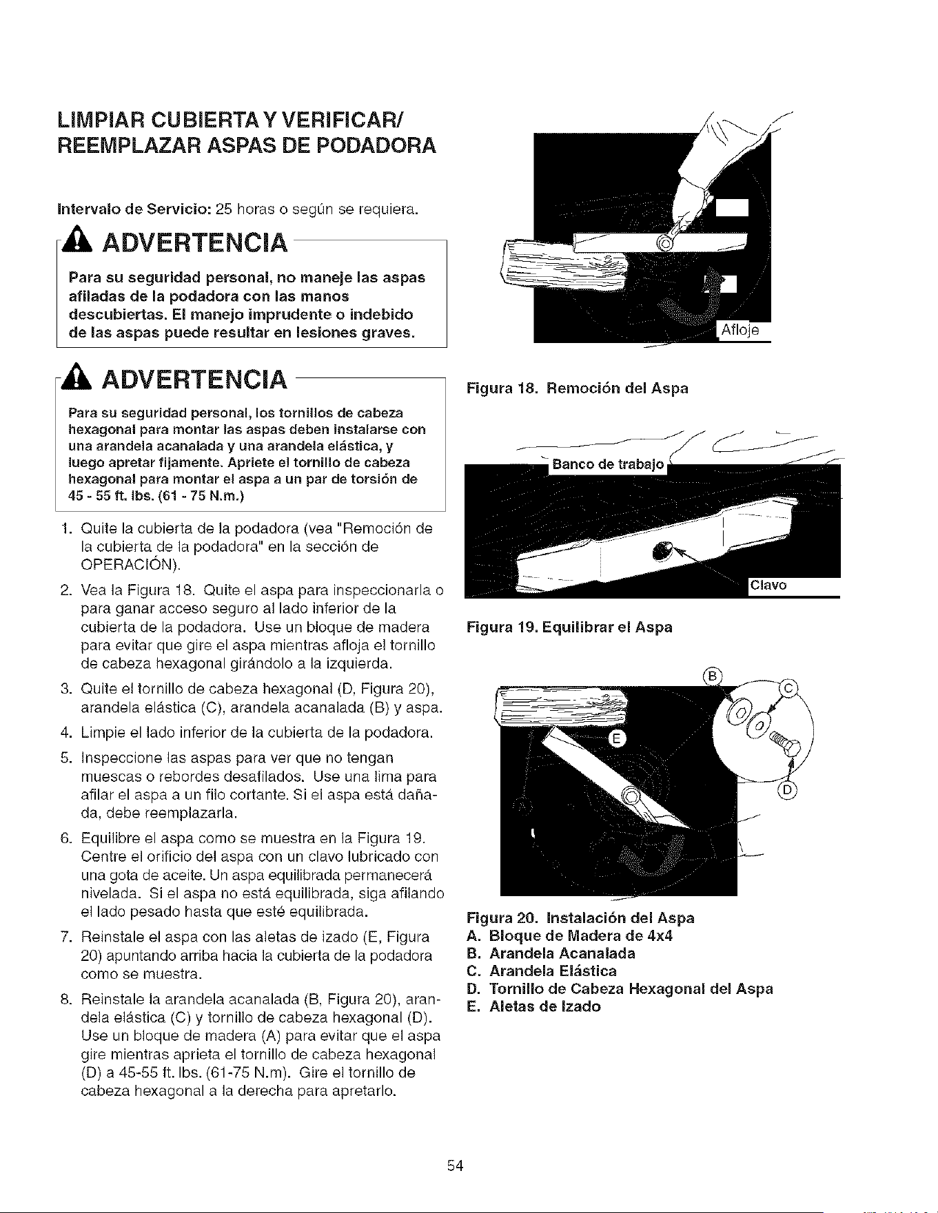
LIMPIAR CUBIERTA Y VERIFICAR/
REEIVIPLAZAR ASPAS DE PODADORA
Intervalo de Servicio: 25 horas o segun se requiera.
AOVERTENCIA
Para su seguridad personal, no maneje lae aspas
afiladas de la podadora con las manos
deacubiertas. El manejo imprudente o indebido
de las aspas puede resultar en lesiones graves.
ADVERTENCIA
Para su seguridad personal, los tornillos de cabeza
hexagonal para montar las aspas deben instalarse con
una arandela acanalada y una arandela el_stica, y
luego apretar fijamente. Apriete el tornillo de cabeza
hexagonal para montar el aspa aun par de torsiSn de
45 - 55 ft, Ibs. ({$1- 75 N.rn.)
1. Quite la cubierta de ]a podadora (vea "Remoci6n de
la cubierta de la podadora" en la secci6n de
OPERACION).
2. Vea la Figura 18. Quite el aspa para inspeccionarla o
para ganar acceso seguro al lado inferior de la
cubierta de la podadora. Use un bloque de madera
para evitar que gire el aspa mientras afloja el tornillo
de cabeza hexagonal girAndolo a la izquierda.
3. Quite el tornillo de cabeza hexagonal (D, Figura 20),
arandela elAstica (C), arandela acanalada (B) y aspa.
4. Limpie el lado inferior de la cubierta de la podadora.
5. Inspeccione las aspas para ver que no tengan
muescas o rebordes desafilados. Use una lima para
afilar el aspa a un filo cortante. Si el aspa est,. da5a-
da, debe reemplazarla.
6. Equilibre el aspa como se muestra en la Figura 19.
Centre el orificio del aspa con un clavo lubricado con
una gota de aceite. Un aspa equilibrada permanecer_.
nivelada. Si el aspa no estb. equilibrada, siga afilando
el lade pesado hasta que est_ equilibrada.
7. Reinstale el aspa con las aletas de izado (E, Figura
20) apuntando arriba hacia la cubierta de la podadora
como se muestra.
8. Reinstale la arandela acanalada (B, Figura 20), aran-
dela el_.stica (C) y tornillo de cabeza hexagonal (D).
Use un bloque de madera (A) para evitar que el aspa
gire mientras aprieta el tornillo de cabeza hexagonal
(D) a 45-55 ft. Ibs. (61-75 N.m). Gire el tornillo de
cabeza hexagonal a la derecha para apretarlo.
Afloje
Figura 18. Remoci6n del Aspa
Banco de trabajo
Clavo
Fignra 19. Equilibrar el Aspa
Fignra 20. Instalaci6n del Aspa
A. Bloque de Madera de 4x4
B. Arandela Acanalada
C. Arandela El&stica
D. Tornillo de Cabeza Hexagonal del Aspa
E. Aletas de Izado
54
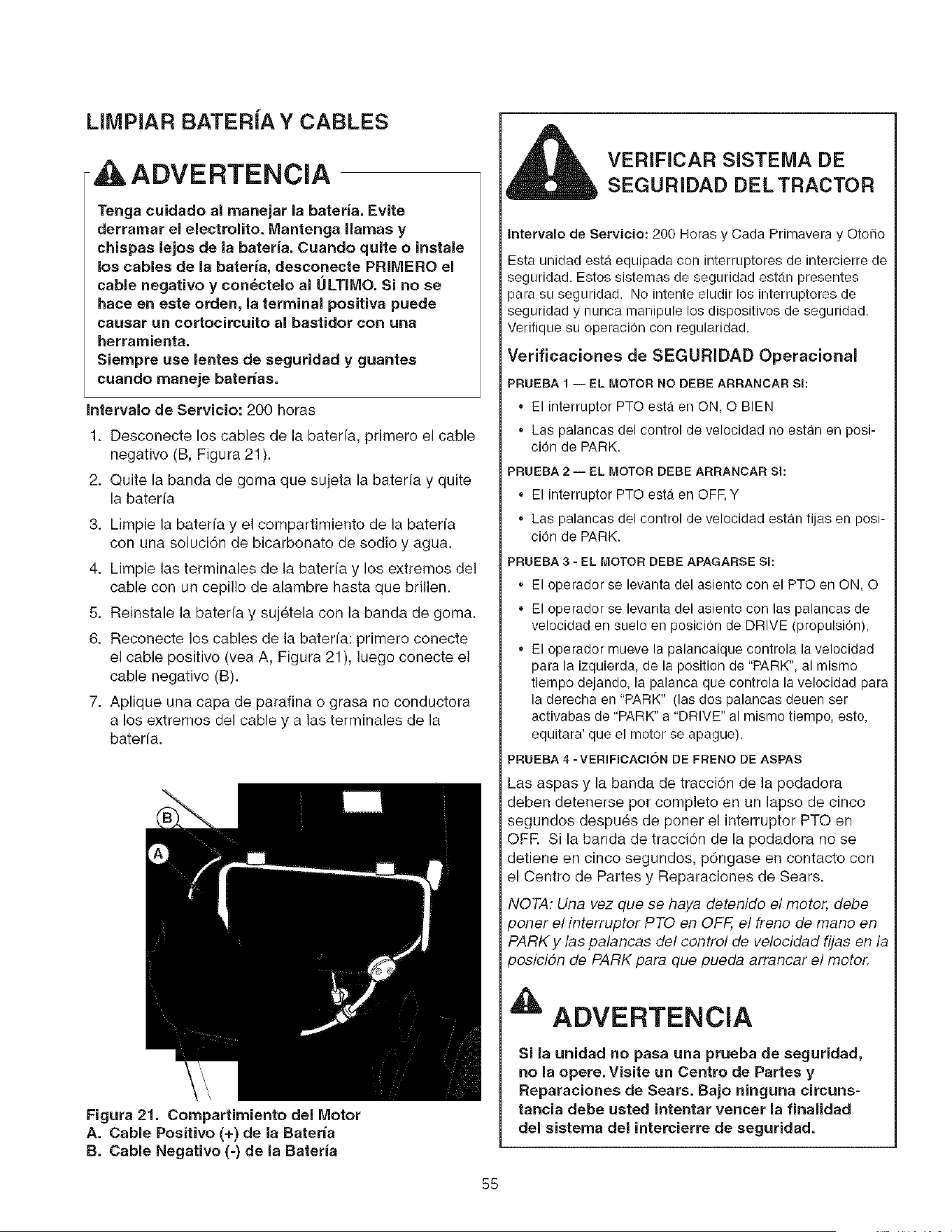
LIMPIAR BATERJA Y CABLES
ADVERTENCIA
Tenga cuidado al manejar la bateria. Evite
derramar el electrolito. Mantenga llamas y
chispas lejos de la bateria. Cuando quite o instale
los cables de la bateria, desconecte PRIMERO el
cable negativo y con_ctelo al ULTIMO. Si no se
haee en este ordeR, la terminal positiva puede
causar un cortocircuito al bastidor con una
herramienta.
Siempre use lentes de seguridad y guantes
cuando maneje baterias.
intervalo de Servicio: 200 horas
1. Desconecte los cables de la baterfa, primero el cable
negativo (B, Figura 21).
2. Quite la banda de goma que sujeta la bateria y quite
la baterfa
3. Limpie ia baterfa y el compartimiento de ]a baterfa
con una soluci6n de bicarbonate de sodio y agua.
4. Limpie las terminales de la baterfa y los extremos del
cable con un cepillo de alambre hasta que brillen.
5. Reinstale la bateria y suj_tela con ]a banda de goma.
6. Reconecte los cables de la baterfa: primero conecte
el cable positivo (vea A, Figura 21), ]uego conecte el
cable negativo (B).
7. Aplique una capa de parafina o grasa no conductora
a los extremos del cable y aias terminales de la
baterfa.
Figura 21. Compartirniento del Motor
A. Cable Positivo (+) de la Bateria
B. Cable NegaUvo (-) de la Bateria
VER[FICAR SISTEMA DE
SEGURIDAD DEL TRACTOR
Intervalo de Servicio: 200 Horas y Cada Primavera y Otofio
Esta unidad esta equipada con interruptores de intercierre de
seguridad. Estos sistemas de seguridad estan presentes
)ara su seguridad. No intente eludir los interruptores de
seguridad y nunca rnanipule los dispositivos de seguridad.
Verifique su operaci0n con regularidad.
Verificaciones de SEGURIDAD Operacional
PRUEBA 1 -- EL MOTOR NO DEBE ARRANCAR Sl:
El interruptor PTO ester en ON, O BIEN
* Las palancas del control de velocidad no estan en posi-
cion de PARK.
PRUEBA 2 -- EL MOTOR DEBE ARRANCAR Sl:
El interruptor PTO esta en OFF, Y
Las palancas del control de velocidad estan fijas en posi-
cion de PARK.
PRUEBA 3 - EL MOTOR DEBE APAGARSE Sl:
El operador se levanta del asiento con el PTO en ON, O
El operador se levanta del asiento con las palancas de
velocidad en suelo en posicion de DRIVE (propulsion),
El operador mueve la palancaique controla la velocidad
para la izquierda, de la position de "PARK", al mismo
tiempo dejando, la palanca que controla la velocidad para
la derecha en "PARK" (las dos palancas deuen ser
activabas de "PARK" a "DRIVE" al mismo tiempo, esto,
equitara' que el motor se apague).
PRUEBA 4 -VERIFICACION DE FRENO DE ASPAS
Las aspas y la banda de tracci6n de la podadora
deben detenerse por completo en un lapso de cinco
segundos despu_s de poner el interruptor PTO en
OFR Si la banda de tracciOn de la podadora no se
detiene en cinco segundos, p6ngase en contacto con
el Centre de Partes y Reparaciones de Sears.
NOTA: Una vez que se haya detenido el motor, debe
_oner el interruptor PTO en OFF, el freno de mano en
PARK y las palancas det control de velocidad fijas en la
_osicidn de PARK para que pueda arrancar e! motor.
ADVERTENCIA
Si la unidad no pasa una prueba de seguridad,
no la opere.Visite un Centro de Partes y
Reparaciones de Sears. Bajo ninguna circuns-
tancia debe usted intentar vencer la finalidad
del sistema del intercierre de seguridad.
55
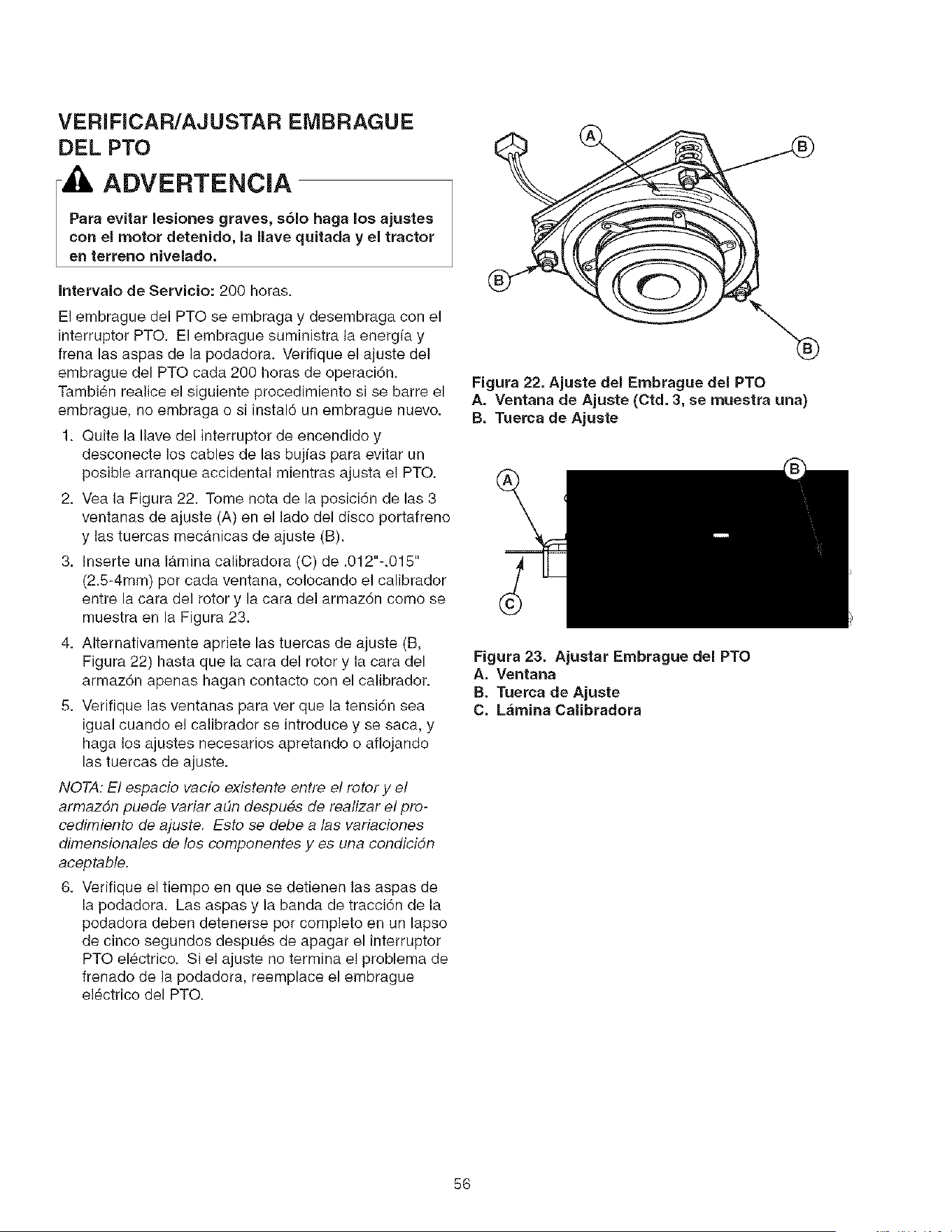
VERIFICAR/AJUSTAR EMBRAGUE
DEL PTO
- IL ADVERTENCIA
Para evitar lesiones graves, sAIo haga los ajustes
con el motor detenido, la nave quitada y el tractor
en terreno nivelado,
Intervalo de Servicio: 200 horas.
El embrague del PTO se embraga y desembraga con el
interruptor PTO. El embrague suministra la energia y
frena las aspas de la podadora. Verifique el ajuste del
embrague del PTO cada 200 horas de operaciAn.
TambiAn rea]ice el siguiente procedimiento si se barre el
embrague, no embraga o si instalA un embrague nuevo.
1. Quite la Ilave de] interrupter de encendido y
descenecte los cables de las bujfas para evitar un
posible arranque accidental mientras ajusta el PTO.
2. Vea la Figura 22. Tome nota de la posiciAn de las 3
ventanas de ajuste (A) en el lade de] disco pertafreno
y las tuercas mecanicas de ajuste (B).
3. Inserte una lamina calibradora (C) de .012"-.015"
(2.5-4mm) per cada ventana, colocando el calibrador
entre la cara del rotor y la cara del armazAn come se
muestra en la Figura 23.
4. Alternativamente apriete las tuercas de ajuste (B,
Figura 22) hasta que la cara del rotor y ]a cara del
armazAn apenas hagan contacto con el calibrador.
5. Verifique las ventanas para ver que la tensiAn sea
igual cuando el calibrador se introduce y se saca, y
haga los ajustes necesaries apretando o aflojando
las tuercas de ajuste.
NOTA: El espacio vac[o existente entre et rotor y et
armazdn puede variar at_n despues de realizar el pro-
cedimiento de ajuste. Esto se debe alas variaciones
dimensionates de los componentes yes una condicidn
aceptable.
6. Verifique el tiempo en que se detienen las aspas de
la podadora. Las aspas y la banda de tracciAn de la
podadora deben detenerse per complete en un lapse
de cinco segundos despues de apagar el interrupter
PTO elActrico. Si el ajuste no termina el problema de
frenado de la podadora, reemplace el embrague
elActrico del PTO.
Figura 22. Ajuste del Embrague del PTO
A. Ventana de Ajuste (Ctd. 3, se muestra una)
B. Tuerca de Ajuste
Figura 23. Ajustar Embrague del PTO
A. Ventana
B. Tuerca de Ajuste
C. L&mina Calibradora
56
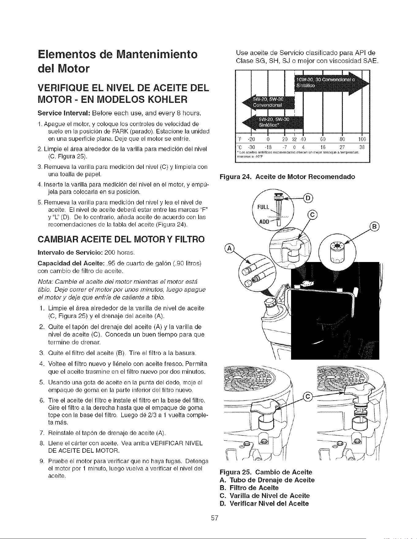
Elernentos de Mantenimiento
del Motor
VERIFIQUE EL NIVEL DE ACEITE DEL
MOTOR - EN MODELOS KOHLER
Service Interval: Before each use, and every 8 hours.
1. Apague el motor, y coloque los controles de velocidad de
suelo en la posicion de PARK (parado). Estacione la unidad
en una superficie plana. Deje que el motor se enfrfe.
2. Limpie el area alrededor de la varilla para medicion del nivel
(C, Figura 25).
3. Remueva la varilla para medicion del nivel (C) y Ifmpiela con
una toalla de papel.
4. Inserte la varilla para medicion del nivel en el motor, y empL_-
jela para colocarla en su posicion.
5. Remueva la varilla para medicion del nivel y lea el nivel de
aceite. El nivel de aceite debera estar entre las marcas "F"
y "E' (D). De Io contrario, a_ada aceite de acuerdo con las
recomendaciones de la tabla del aceite (Figura 24).
CAMBIAR ACEiTE DEL MOTOR Y FILTRO
Intervalo de Servicio: 200 horas.
Capacidad del Aceite: .95 de cuarto de galon (.90 litros)
con cambio de filtro de aceite.
Nota: Cambie el aceite de/motor mientras el motor estb
tibio. Deje correr el motor por unos minutos, luego apague
et motor y deje que enfrfe de caliente a tibio.
1. Limpie el _rea alrededor de la varilla de nivel de aceite
(C, Figura 25) y el drenaje del aceite (A).
2. Quite el tap6n del drenaje del aceite (A) y la varilla de
nivel de aceite (C). Conceda un buen tiempo para que
termine de drenar.
3. Quite el filtro del aceite (B). Tire el filtro a la basura.
4. Voltee el filtro nuevo y II_nele con aceite fresco. Permita
que el aceite trasmine en el filtro nuevo por dos minutos.
5. Usando una gota de aceite en la punta del dedo, moje el
empaque de goma en la parte inferior del filtro nuevo.
6. Tire el aceite del filtro e instale el filtro en la base del filtro.
Gire el filtro a la derecha hasta que el empaque de goma
tope con la base del filtro. Luego de 2/3 a 1 vuelta comple-
ta mas.
7. Reinstale el tapon de drenaje de aceite (A).
8. Llene el carter con aceite. Yea arriba VERIFICAR NIVEL
DE ACEITE DEL MOTOR.
9. Pruebe el motor para verificar que no haya fugas. Detenga
el motor por 1 minuto, luego vuelva a verificar el nivel del
aceite.
Use aceite de Servicio clasificado para API de
Clase SG, SH, SJ o mejor con viscosidad SAE.
l_wEtll>
4t[]!1
,,Bsm
F -_o _ 2'o377o 7o 7o loo
C -30 -18 -7 0 4 16 27 38
• Los aceftes sint_tlo_,, ecomendado,, of_ecen un meio_ af a_que a tempe_atu_
nl_nor_ a IQ°F
Figura 24. Aceite de Motor Recornendado
Figura 25. Cambio de Aceite
A. Tubo de Drenaje de Aceite
B. Filtro de Aceite
C. Varilla de Nivel de Aceite
D. Verificar Nivel del Aceite
57
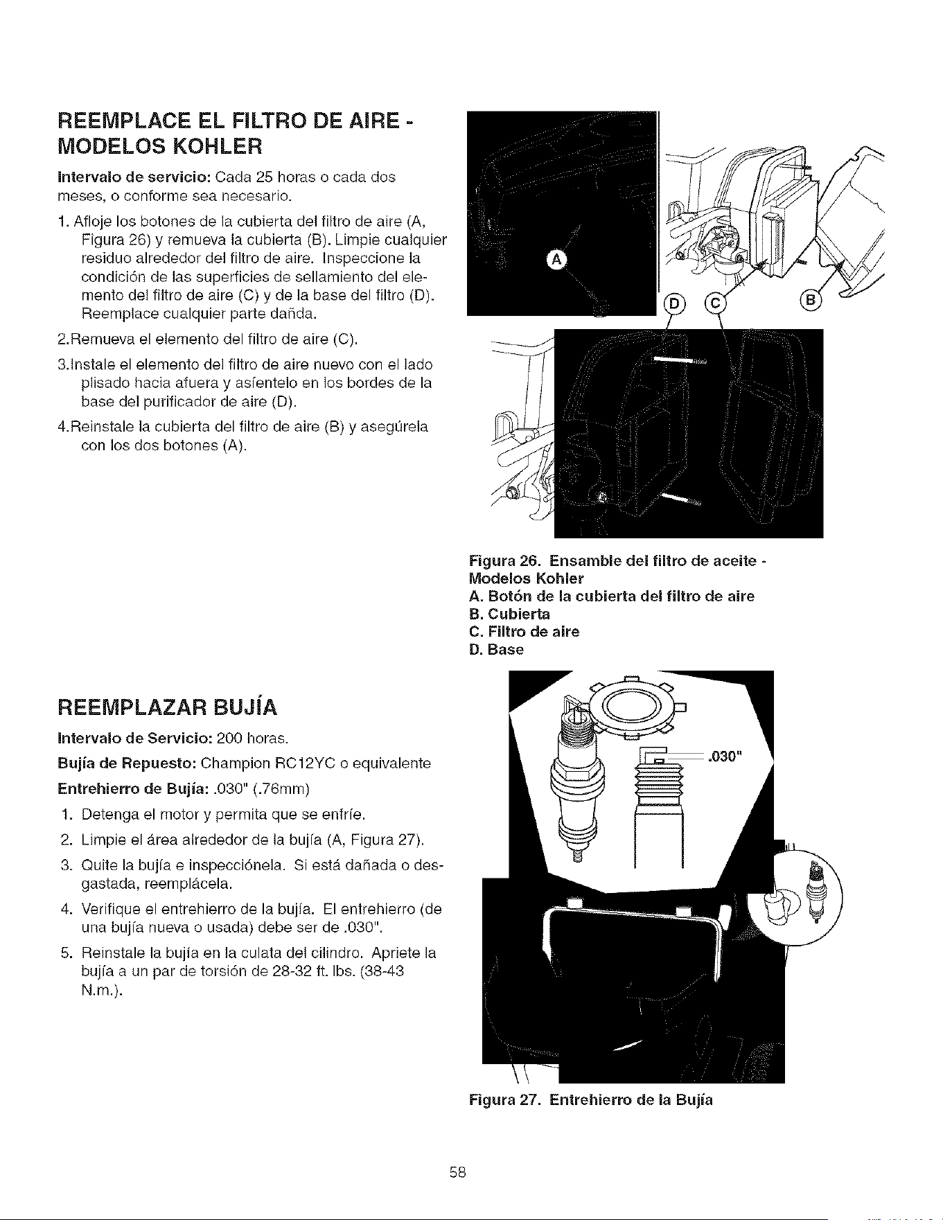
REEMPLACE EL FILTRO DE AIRE -
MODELOS KOHLER
Intervalo de servicio: Cada 25 horas o cada dos
meses, o conforme sea necesario.
1. Afloje los botones de la cubierta del filtro de aire (A,
Figura 26) y remueva la cubierta (B). Limpie cualquier
residue alrededor del filtro de aire. Inspeccione la
condici6n de las superficies de sellamiento del ele-
mento del filtro de aire (C) y de la base del filtro (D).
Reemplace cualquier parte daSda.
2.Remueva el elemento del filtro de aire (C).
3.1nstale el elemento del filtro de aire nuevo con el lado
plisado hacia afuera y asfentelo en los bordes de la
base del purificador de aire (D).
4.Reinstale ]a cubierta del filtro de aire (B) y asegurela
con los dos botones (A).
\\
Figura 26. Ensamble del filtro de aceite -
Modelos Kohler
A. Bot6n de la cubierta del filtro de aire
B. Cubierta
C. Filtro de aire
D. Base
REEMPLAZAR BUJJA
Intervalo de Servicio: 200 horas.
Bujia de Repuesto: Champion RC12YC o equivalente
Entrehierro de Bujia: .030" (.76ram)
1. Detenga el motor y permita que se enfrfe.
2. Limpie el _.rea alrededor de la bujfa (A, Figura 27).
3. Quite la bujfa e inspecci6nela. Siesta daSada o des-
gastada, reemplacela.
4. Verifique el entrehierro de la bujia. El entrehierro (de
una bujfa nueva o usada) debe set de .030".
5. Reinstale la bujia en Jaculata del cilindro. Apriete la
bujfa a un par de torsi6n de 28-32 ft. Ibs. (38-43
N.m.).
Figura 27. Entrehierro de la Bujia
58
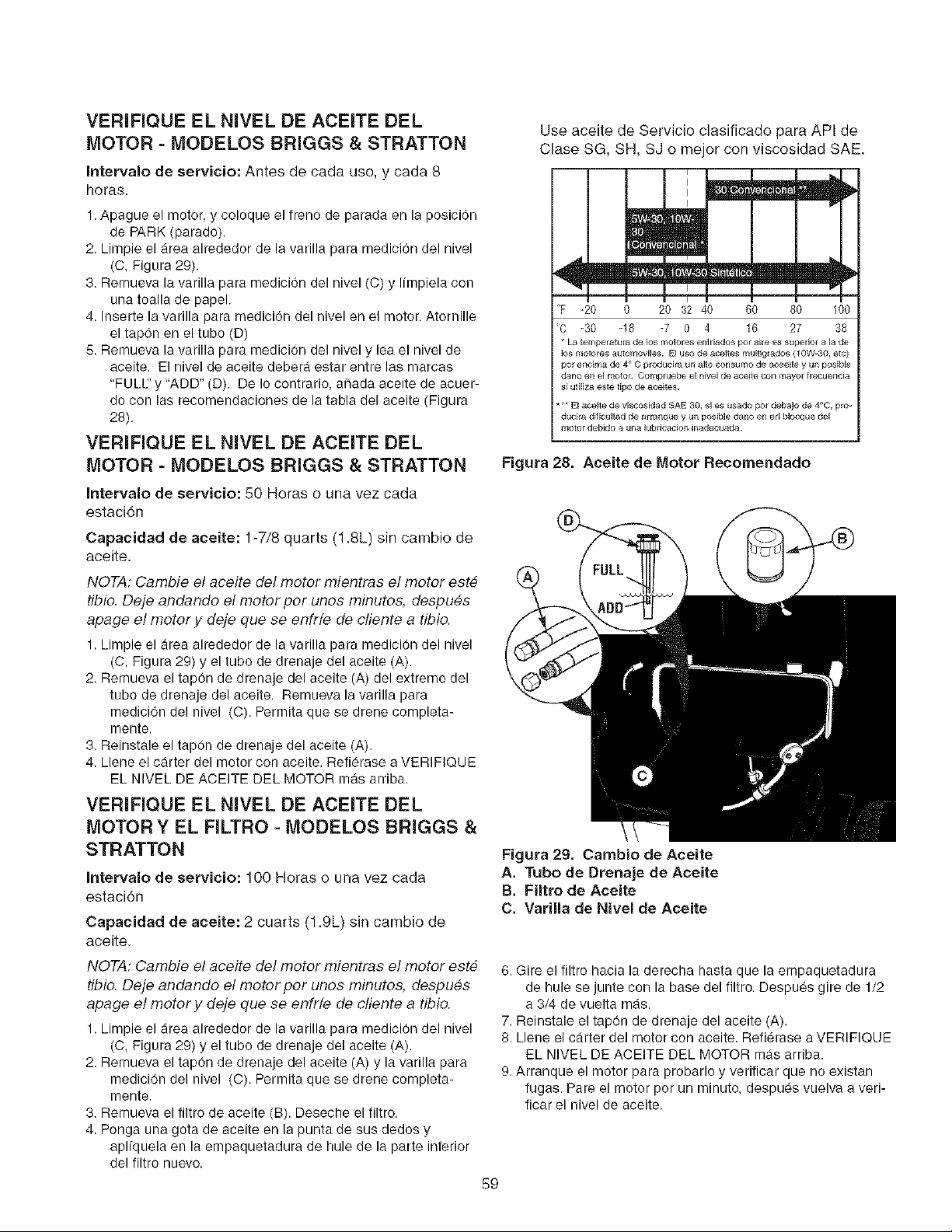
VERIFIQUE EL NIVEL DE ACEITE DEL
MOTOR - MODELOS BRIGGS & STRATTON
Intervalo de servicio: Antes de cada uso, y cada 8
horas.
1, Apague el motor, y coloque el freno de parada en la posicion
de PARK (parado).
2, Limpie el area alrededor de la varilla para medicion del nivel
(C, Figura 29).
3. Remueva la varilla para medicion del nivel (C) y limpiela con
una toalla de papel.
4. Inserte la varilla para medicion del nivel en el motor. Atornille
el tap6n en el tubo (D)
5. Remueva la varilla para medicion del nivel y lea el nivel de
aceite. El nivel de aceite debera estar entre las marcas
"FULIL' y "ADD" (D). De Io contrario, a_ada aceite de acuer-
do con las recomendaciones de la tabla del aceite (Figura
28).
VERIFIQUE EL NIVEL DE ACEITE DEL
MOTOR - MODELOS BRIGGS & STRATTON
Intervalo de servicio: 50 Horas o una vez cada
estaci6n
Capacidad de aceite: 1-7/8 quarts (1.8L) sin cambio de
aceite.
NOTA: CambJe el aceJte de/motor mientras el motor est#
tibio. Deje andando et motor pot unos minutos, despu#s
apage el motor y deje qua se enfrfe de ctiente a tibio.
1. Limpie el area alrededor de la varilla para medici0n del nivel
(C, Figura 29) y el tubo de drenaje del aceite (A).
2. Remueva el tapon de drenaje del aceite (A) del extremo del
tubo de drenaje del aceite. Remueva la varilla para
medici6n del nivel (C). Permita qua se drene completa-
mente.
3. Reinstale el tapon de drenaje del aceite (A).
4. Llene el carter del motor con aceite. Refierase a VERIFIQUE
EL NIVEL DE ACEITE DEL MOTOR mas arriba.
VERiFIQUE EL NiVEL DE ACEITE DEL
MOTOR Y EL FILTRO - MODELOS BRIGGS &
STRATTON
Intervalo de servicio: 100 Horas o una vez cada
estaci6n
Capacidad de aceite: 2 cuarts (1.9L) sin cambio de
aceite.
NOTA: CambJe el aceJte del motor mientras el motor est#
tibio. Deje andando el motor por unos minutes, despues
apage el motor y deje qua se enfrfe de cliente a tibio.
1. Limpie el area alrededor de la varilla para medicion del nivel
(C, Figura 29) y el tubo de drenaje del aceite (A).
2. Remueva el tapon de drenaje del aceite (A) y la varilla para
medici6n del nivel (C). Permita qua se drene completa-
mente.
3. Remueva el filtro de aceite (B). Deseche el filtro.
4. Ponga una gota de aceite en la punta de sus dedos y
aplfquela en la empaquetadura de hule de la parte inferior
del filtro nuevo.
59
Use aceite de Servicio clasificado para API de
Clase SG, SH, SJ o major con viscosidad SAE.
F -20 0 203240 GO 100
c -30 -18 -7 0 4 16 27 38
* La temperatura de _os motores enfriados pot aEre es superio[ a la de
los motores automovBes. El uso de aceites multiglados (10W-30, elc)
pot encima de 4 C producira un alto consumo de aceeite y un posible
dano en el motor. Comp_uebe el nivel de aceite con mayor flecuencia
si utilJza este tipo de aceites.
** El aeeite de viscosidad SAE 30, si es usado pot debajo de 4°0, pro-
ducila dJfioultad de arral_que y ul_ posible dano en erl blooque del
motor debido a una lubricacion inadecuada.
Figura 28, Aceite de Motor Recomendado
Figura 29. Cambio de Aceite
A. Tubo de Drenaje de Aceite
B. Filtro de Aceite
C. VarilJa de Nivel de Aeeite
6. Gire el filtro hacia la derecha hasta que la empaquetadura
de hule se junte con la base del filtro. Despues gire de 1/2
a 3/4 de vuelta mas.
7. Reinstale el tap6n de drenaje del aceite (A).
8. Liana el carter del motor con aceite. Refierase a VERIFIQUE
EL NIVEL DE ACEITE DEL MOTOR mas arriba.
9. Arranque el motor para probarlo y verificar que no existan
fugas. Pare el motor por un minuto, despues vuelva a veri-
ficar el nivel de aceite.
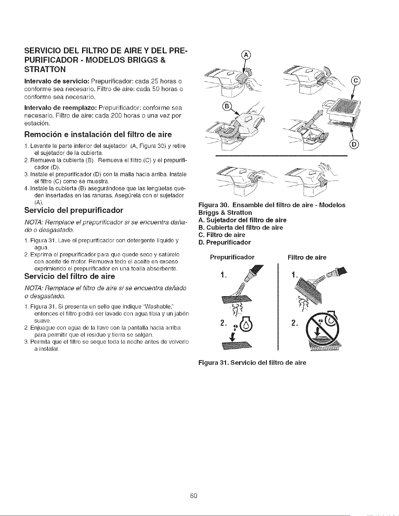
SERVlCIO DEL FILTRO DE AIRE Y DEL PRE-
PURIFICADOR - MODELOS BRIGGS &
STRATTON
Intervalo de servicio: Prepurificador: cada 25 horas o
conforme sea necesario. Filtro de aire: cada 50 horas o
conforme sea necesario.
Intervalo de reemplazo: Prepurificador: conforme sea
necesado. Filtro de aire: cada 200 horas o una vez per
estaci6n.
Remoci6n e instalaci6n del filtro de aire
1. Levante la parte inferior del sujetador (A, Figura 30) y retire
el sujetador de la cubierta.
2. Remueva la cubierta (B). Remueva el filtro (C) y el prepurifi-
cador (D).
3. Instale el prepurificador (D) con la malla hacia arriba. Instale
el filtro (C) come se muestra.
4. Instale la cubierta (B) asegurandose que las leng0etas que-
den insertadas en las ranuras. AsegOrela con el sujetador
(A).
Servicio del prepurificador
NOTA: Remplace el prepurificador si se encuentra daha-
do o desgastado.
1. Figura 31. Lave el prepurificador con detergente I{quido y
agua.
2. Exprima el prepurificador para que quede seco y saturelo
con aceite de motor. Remueva todo el aceite en exceso
exprimiendo el prepurificador en una toalla absorbente.
Servicio del filtro de aire
NOTA: Remplace et fittro de aire si se encuentra daiiado
o desgastado.
1. Figura 31. Si presenta un sello que indique "Washable,"
entonces el filtro podra ser lavado con agua tibia y un jabon
suave.
2. Enjuague con agua de la Ilave con la pantalla hacia arriba
para permitir que el residue y tierra se salgan.
3. Permita que el filtro se seque toda la noche antes de volverlo
a instalar.
Figura 30, Ensamble del filtro de aire - Modelos
Briggs & Stratton
A. Sujetador del filtro de aire
B. Cubierta del filtro de aire
C. Filtro de aire
D. Prepurificador
Prepurificador
Filtro de aire
Figura 31, Servicio del filtro de aire
60
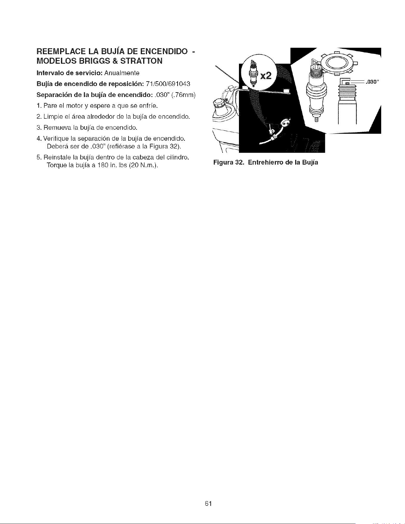
REEMPLACE LA BUJ|A DE ENCENDIDO -
MODELOS BRIGGS & STRATTON
Intervalo de servicio: Anualmente
Bujia de encendido de reposici6n: 71/500/691043
Separaci6n de la bujia de encendido: .030" (.76mm)
1. Pare el motor y espere a que se enfrie.
2. Limpie el Area alrededor de la bujfa de encendido.
3. Remueva la bujfa de encendido.
4. Verifique la separaci6n de la bujia de encendido.
DeberA set de .030" (refi_rase a la Figura 32).
5. Reinstale la bujfa dentro de la cabeza del cilindro.
Torque la bujfa a 180 in. Ibs (20 N.m.).
Figura 32. Entrehierro de la Bujia
61
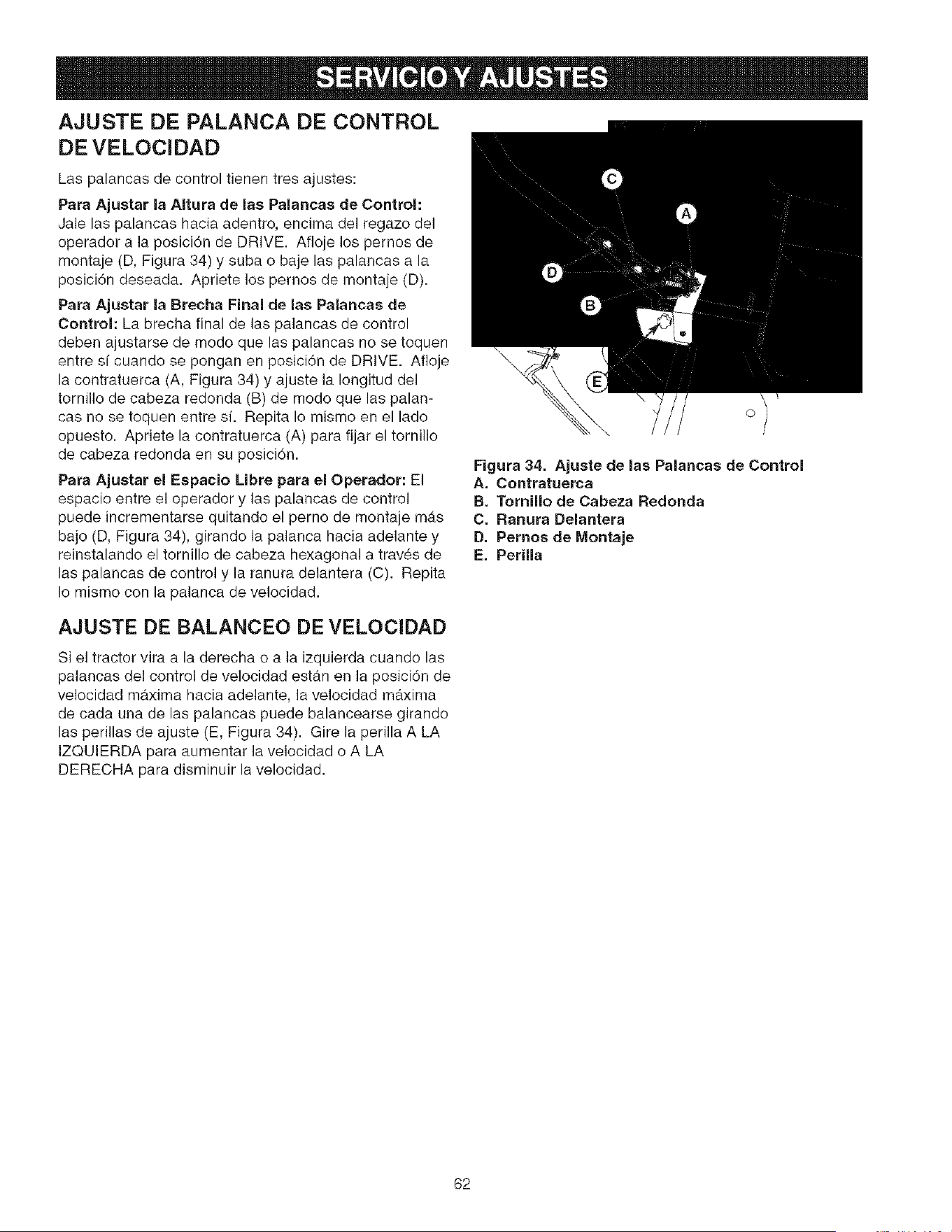
=
AJUSTE DE PALANCA DE CONTROL
DE VELOClDAD
Las palancas de control tienen tres ajustes:
Para Aiustar la AItura de las Palancas de Control:
Jale las palancas hacia adentro, encima del regazo del
operador a la posici6n de DRIVE. Afloje los pernos de
montaje (D, Figura 34) y suba o baje las palancas a la
posici6n deseada. Apriete los pernos de montaje (D).
Para Ajustar la Brecha Final de las Palancas de
Control: La brecha final de las palancas de control
deben ajustarse de modo que las palancas no se toquen
entre sf cuando se pongan en pesici6n de DRIVE. Afloje
la contratuerca (A, Figura 34) y ajuste la Iongitud del
ternillo de cabeza redonda (B) de mode que las palan-
cas no se toquen entre si. Repita Io mismo en el lade
opuesto. Apriete la contratuerca (A) para fijar el tornillo
de cabeza redonda en su posici6n.
Para Ajustar el Espacio Libre para el Operador: El
espacio entre el eperador y las palancas de control
puede incrementarse quitando el perne de mentaje mAs
bajo (D, Figura 34), girando la palanca hacia adelante y
reinstalando el tornillo de cabeza hexagonal a tray, s de
las palancas de control y la ranura delantera (C). Repita
Io misme con la palanca de velecidad.
©
Figura 34. Ajuste de las Palancas de Control
A. Contratuerca
B. Tornillo de Cabeza Redonda
C. Ranura Delantera
D. Pernos de Montaje
E. Perilla
AJUSTE DE BALANCEO DE VELOCIDAD
Si el tractor vira a la derecha o a la izquierda cuando las
palancas del control de velocidad estAn en la pesiciSn de
velocidad maxima hacia adelante, la velocidad maxima
de cada una de las palancas puede balancearse girando
las perillas de ajuste (E, Figura 34). Gire ]a perilla A LA
IZQUIERDA para aumentar la velocidad o A LA
DERECHA para disminuir la velocidad.
62
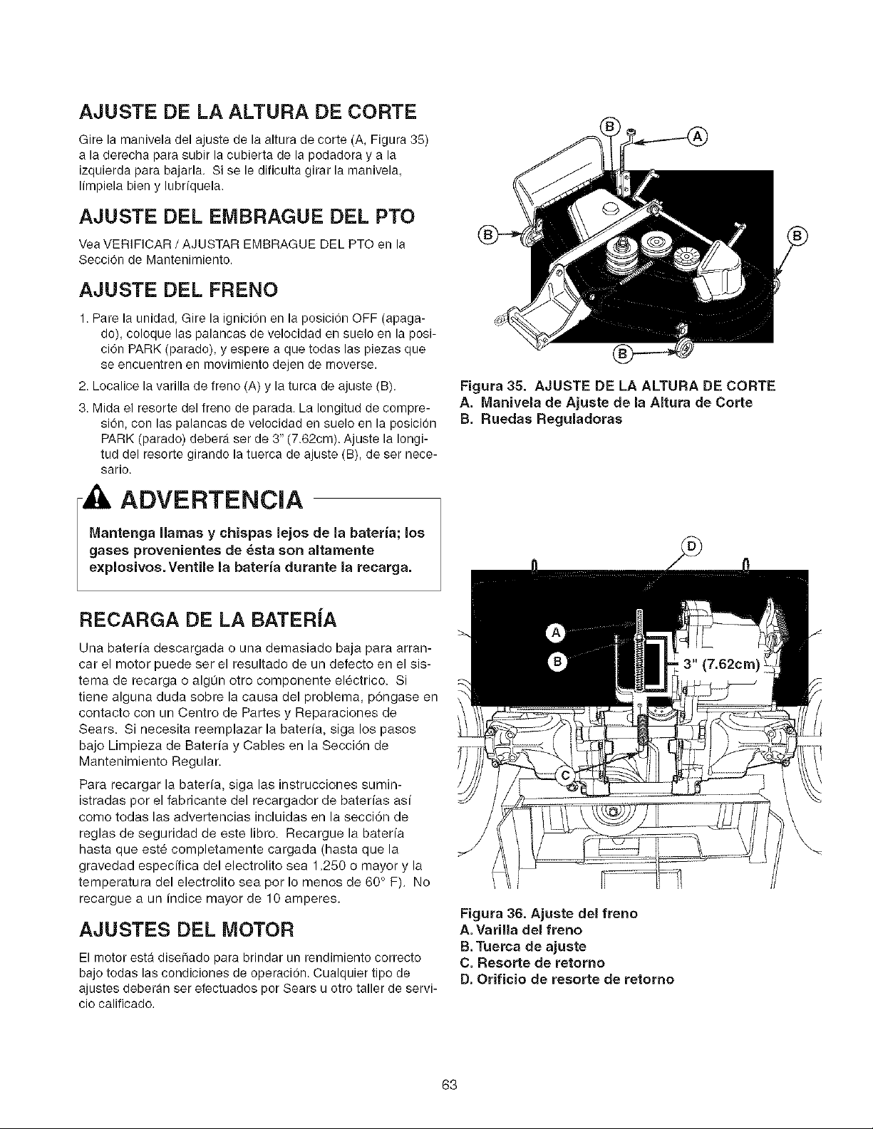
AJUSTE DE LA ALTURA DE CORTE
Gire la manivela del ajuste de la altura de corte (A, Figura 35)
a la derecha para subir la cubierta de la podadora y a la
izquierda para bajarla. Si se le dificulta girar la manivela,
limpiela bien y lubriquela.
AJUSTE DEL EMBRAGUE DEL PTO
Vea VERIFICAR / AJUSTAR EMBRAGUE DEL PTO en la
SecciOn de Mantenimiento.
AJUSTE DEL FRENO
1. Pare la unidad, Gire la ignicion en la posicion OFF (apaga-
do), coloque las palancas de velocidad en suelo en la posi-
ciOn PARK (parado), y espere a que todas las piezas que
se encuentren en nlovimiento dejen de moverse.
2. Localice la varilla de freno (A) y la turca de ajuste (B).
3. Mida el resorte del freno de parada. La Iongitud de compre-
sion, con las palancas de velocidad en suelo en la posicion
PARK (parado) debera ser de 3" (7.62cm). Ajuste la Iongi-
tud del resorte girando la tuerca de ajuste (B), de ser nece-
sario.
ADVERTENCIA
IVlantenga llamas y chispas lejos de la bateria; los
gases provenientes de _sta son altamente
explosivos. Ventile la bateria durante la recarga,
RECARGA DE LA BATERJA
Una bateria descargada o una demasiado baja para arran-
car el motor puede ser el resultado de un defecto en el sis-
tema de recarga o algLin otro componente el_ctrico. Si
tiene alguna duda sobre la causa del problema, p6ngase en
contacto con un Centro de Partes y Reparaciones de
Sears. Si necesita reemplazar la bateria, siga los pasos
bajo Limpieza de Bateria y Cables en la Secci6n de
Mantenimiento Regular.
Para recargar la bateria, siga las instrucciones sumin-
istradas por el fabricante del recargador de baterias asi
como todas las advertencias incluidas en la secci6n de
reglas de seguridad de este libro. Recargue la baterfa
hasta que est6 completamente cargada (hasta que la
gravedad especffica del electrolito sea 1.250 o mayor y la
temperatura del electrolito sea por Io menos de 60 ° F). No
recargue a un indice mayor de 10 amperes.
AJUSTES DEL MOTOR
El motor esta diseiiado para brindar un rendimiento correcto
bajo todas las condiciones de operacion. Cualquier tipo de
ajustes deberan set efectuados por Sears u otro taller de servi-
cio calificado.
Figura 35. AJUSTE DE LA ALTURA DE CORTE
A. Manivela de Ajuste de la Altura de Corte
B. Ruedas Reguladoras
Figura 36. Ajuste del freno
A.Varilla clei freno
B. iuerca de ajuste
C. Resorte de retomo
D. Orifieio de resorte de retorno
63
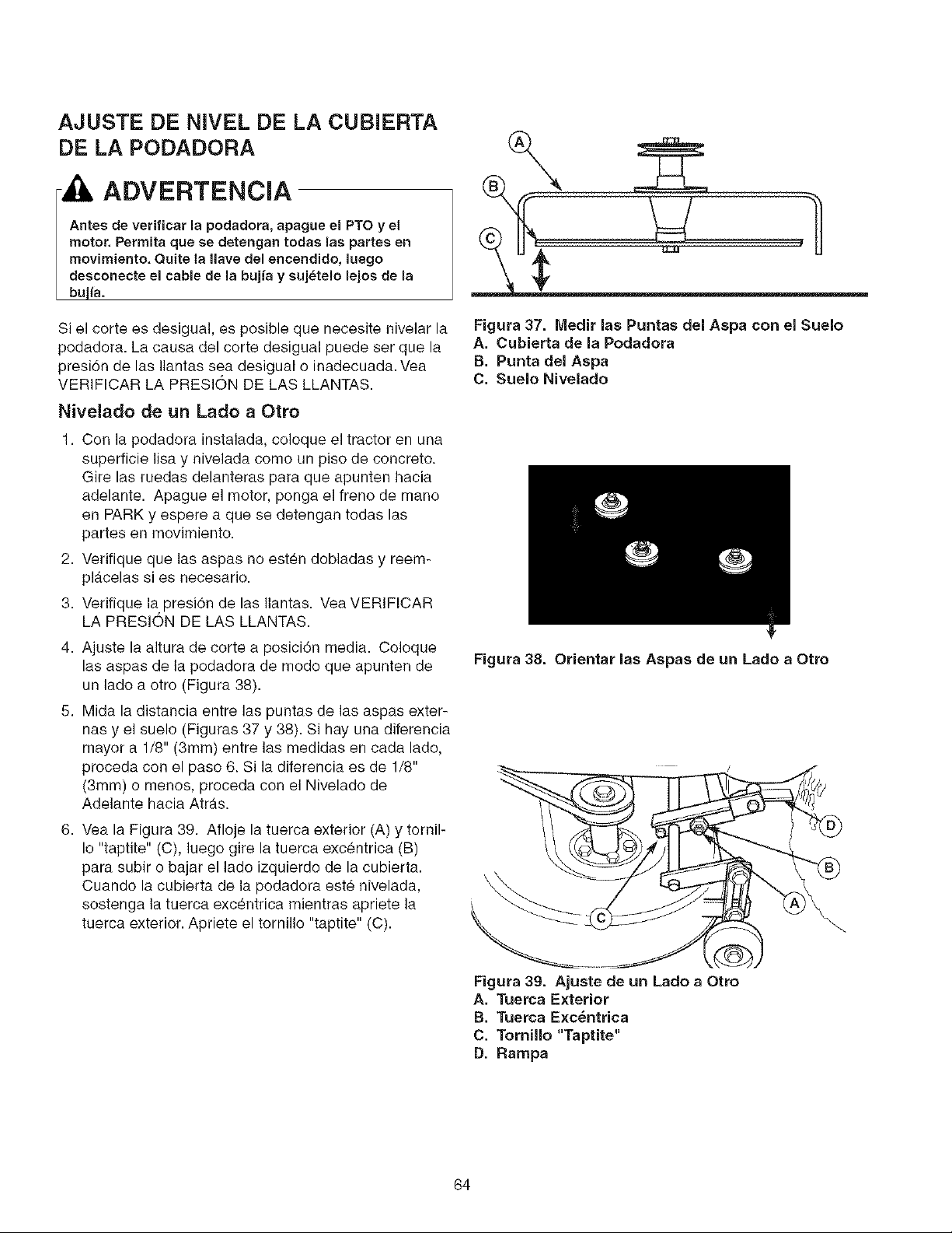
AJUSTE DE NIVEL DE LA CUBIERTA
DE LA PODADORA
ADVERTENClA
Antes de verificar la podadora, apague el PTO y el
motor. Permits que se detengan todas las partes en
movimiento. Quite la Ilave del eneendido, luego
desconecte el cable de la bujia y suj_telo lejos de la
bujia.
Si el corte es desigual, es posible que necesite nivelar la
podadora. La causa del corte desigual puede ser que la
presi6n de las Ilantas sea desigual o inadecuada. Vea
VERIFICAR LA PRESION DE LAS LLANTAS.
Nivelado de un Lado a Otto
1. Con la podadora instalada, coloque el tractor en una
superficie lisa y nivelada como un piso de concreto.
Gire las ruedas delanteras para que apunten hacia
adelante. Apague el motor, ponga el freno de mano
en PARK y espere a que se detengan todas las
partes en movimiento.
2. Verifique que las aspas no esten dobladas y reem-
pl_.celas si es necesario.
3. Verifique la presiTn de las Ilantas. Vea VERIFICAR
LA PRESION DE LAS LLANTAS.
4. Ajuste la altura de cortea posici6n media. Coloque
las aspas de la podadora de modo que apunten de
un lado a otro (Figura 38).
5. Mida la distancia entre las puntas de las aspas exter-
nas y el suelo (Figuras 37 y 38). Si hay una diferencia
mayor a 1/8" (3mm) entre las medidas en cada lado,
proceda con el paso 6. Si la diferencia es de 1/8"
(3mm) o menos, proceda con el Nivelado de
Adelante hacia Atr_.s.
8. Veala Figura 39. Afloje la tuerca exterior (A) y tornil-
Io "taptite" (C), luego gire la tuerca excentrica (B)
pars subir o bajar el lado izquierdo de la cubierta.
Cuando la cubierta de la podadora este nivelada,
sostenga la tuerca exc_ntrica mientras apriete la
tuerca exterior. Apriete el ternillo "taptite" (C).
Figura 37. Medir las Puntas del Asps con el Suelo
A. Cubietta de la Podadora
B. Punts del Asps
C. Suelo Nivelado
Figura 38. Orientar las Aspas de un Lado a Otto
\
\
Figura 39. Ajuste de un Lado a Otto
A. Tuetca Exterior
B. Tuerca Exc_ntrica
C. Tornillo "Taptite"
D. Ramps
64
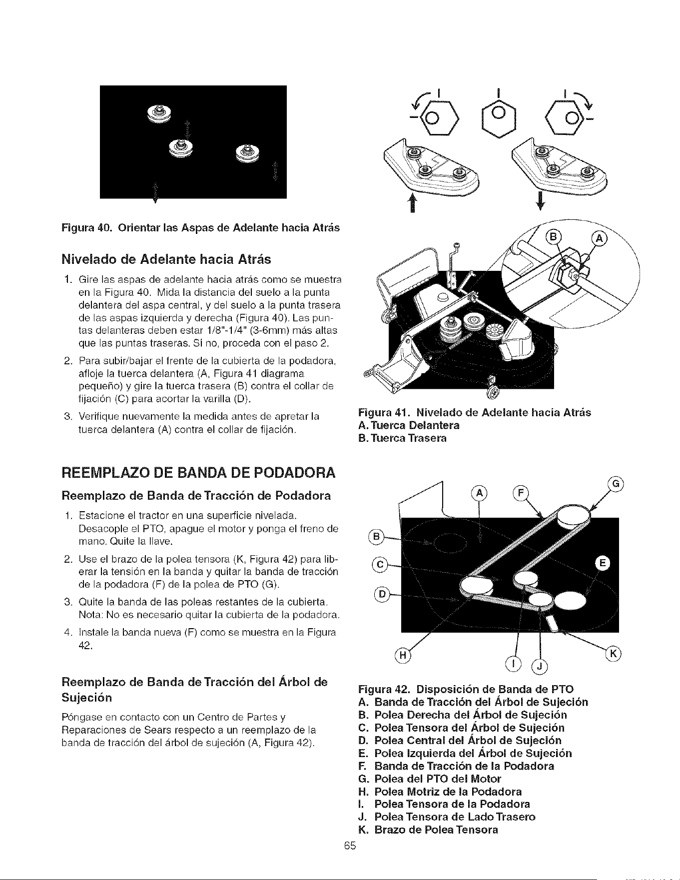
Figura40, Orientarlas Aspas de Adelante hacia Atr;_s
Nivelado de Adelante hacia Atr&s
1. Gire las aspas de adelante hacia atras como se muestra
en la Figura 40. Mida la distancia del suelo a la punta
delantera del aspa central, y del suelo a la punta trasera
de las aspas izquierda y derecha (Figura 40). Las pun-
tas delanteras deben estar 1/8"-1/4" (3-6mm) mas altas
que las puntas traseras. Si no, proceda con el paso 2.
2. Para subir/bajar el frente de la cubierta de la podadora,
afloje la tuerca delantera (A, Figura 41 diagrama
pequeho) y gire la tuerca trasera (B) contra el collar de
fijaci6n (C) para acortar la varilla (D).
3. Verifique nuevamente la medida antes de apretar la
tuerca delantera (A) contra el collar de fijaci6n.
Figura 41. Nivelado de Adelante hacia Atras
A. Tuerca Delantera
B. Tuerca Trasera
REEMPLAZO DE BANDA DE PODADORA
Reernplazo de Banda deTracci6n de Podadora
1. Estacione el tractor en una superficie nivelada.
Desacople el PTO, apague el motor y ponga el freno de
mano. Quite la Ilave.
2. Use el brazo de la polea tensora (K, Figura 42) para lib-
erar la tensi6n en la banda y quitar la banda de tracci6n
de la podadora (F) de la polea de PTO (G).
3. Quite la banda de las poleas restantes de la cubierta.
Nota: No es necesario quitar la cubierta de la podadora.
4. Instale la banda nueva (F) como se muestra en la Figura
42.
Reemplazo de Banda deTracci6n del Arbol de
Sujeci6n
P6ngase en contacto con un Centro de Partes y
Reparaciones de Sears respecto a un reemplazo de la
banda de tracci6n del _.rbol de sujeci6n (A, Figura 42).
Figura 42. Disposici6n de Banda de PTO
A. Banda de Tracci6n del _,rbol de Sujeci6n
B. Polea Derecha del _,rbol de Sujeci6n
C. Polea Tensora del _,rbol de Sujeci6n
D. Polea Central del h,rbol de Sujeci6n
E. Polea Izquierda del _,rbol de Sujeci6n
F. Banda deTracci6n de la Podadora
G. Polea del PTO del Motor
H. Polea Motriz de la Podadora
I. Polea Tensora de la Podadora
J. Polea Tensora de LadoTrasero
K, Brazo de Polea Tensora
65

ALMACENAMIENTO
Antes de almacenar su unidad en la temporada baja, lea las
instrucciones de Mantenimiento y Almacenamiento en la sec-
ci6n de Reglas de Seguridad, luego realice los siguientes
pasos:
,, Desacople el PTO, ponga el freno de mano y quite la
Ilave.
,, Verifique el nivel de todos los fluidos. Verifique todos los
elementos de mantenimiento.
ADVERTENCIA
,_ La vida de la baterfa se incrementara si la quita, y la
coloca en un lugar seco y fresco y la carga por completo
una vez al mes. Si deja la bateria en la unidad,
desconecte el cable negativo.
Es importante evitar que se formen depositos de goma en
las partes esenciales de la instalaci6n de combustible como
el carburador, filtro de la gasolina, tuberia del combustible y
el tanque de gasolina durante el almacenamiento. Adem_ts,
los combustibles mezclados con alcohol (llamados gasohol o
usando etanol o metanol) puede atraer humedad que Ileva a
la separaci6n y formaci6n de _tcidos durante el almace-
namiento. El gas acfdico puede dahar la instalaci6n de com-
bustible de un motor mientras est_ en almacenamiento.
Para evitar problemas con el motor, la instalaci6n de com-
bustible debe vaciarse antes del almacenamiento de 30 dias
o mas. Siga estas instrucciones;
Para proteger el motor, se recomienda el uso del estabi-
lizador de combustible.
Antes de arrancar la unidad despues de estar almacenada:
- Verifique el nivel de todos los fluidos. Verifique todos los
elementos de mantenimiento.
,, Llene con combustible FRESCO.
* Despues de arrancar, permita que el motor se caliente
antes de operar.
Nunca almacene la unidad (con combustible) en una
eetructura cerrada con poca ventilaei6e. Los vaporee
del combustible pueden viajar a una tuente de ignicibe
(come un homo, calentador de agua, etc.) y ocaeionar
una explosi6e,
Los vapores del combustible tambi_n son t6xieos para
los humanos y animalee,
Figura 43. Compartimiento del Motor
A. Filtro de la Gasolina
,ADVERTENCIA
La gasolina es altamente inflamable y debe
manejarse con euidado. Nunca Ilene el tanque
cuando el motor todavia est& caliente por la
reciente operaci6n. No permita que nadie se
acerque con llamas abiertas, cigarros o cerillos al
&tea. Evite nenar demasiado y quite Io derramado
con un trapo,
66
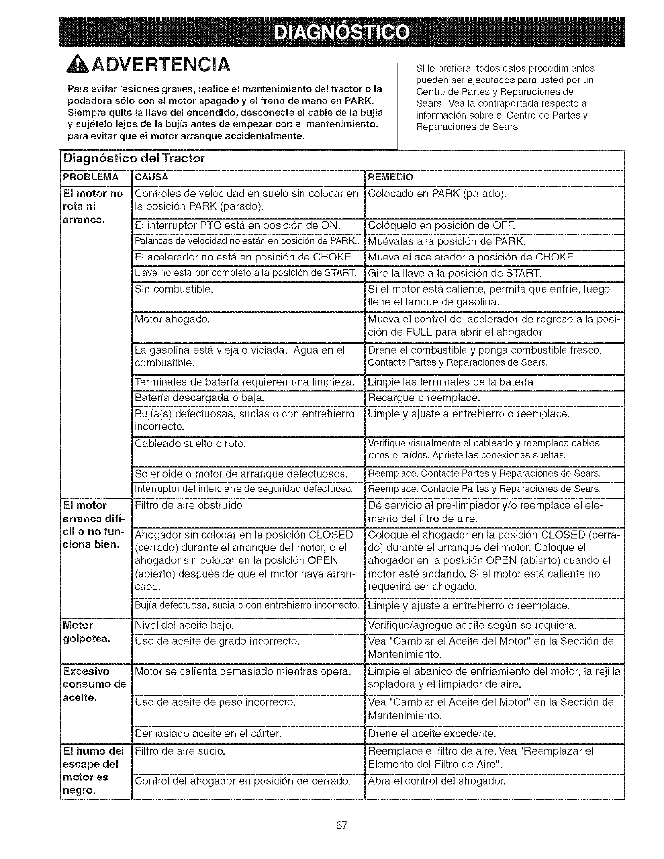
ADVE RTENCIA s, Io prefiere, tedoa estos procedimientos
Para evitar lesionea graves, realice el mantenimiento del tractor o la
podadora sblo con el motor apagado y el freno de mane en PARK.
Siempre quite la Ilave de1 encendido, desconecte el cable de la bujfa
y sujetelo lejos de la bujfa antes de empezar con el mantenimiento,
para evitar que el motor arranque accidentalmente.
pueden ser ejecutados para usted per un
Centre de Partes y Reparaciones de
Sears. Vea la contraportada respecto a
inforrnacion sobre el Centre de Partes y
Reparaciones de Sears.
Diagn6stico del Tractor
PROBLEMA CAUSA REMEDIO
El motor no Controles de velocidad en suelo sin colocar en Colocado en PARK (parade).
rota ni la posici6n PARK (parade).
arranca. El interrupter PTO esta en posici6n de ON. Col6quelo en posici6n de OFR
Palancasde velocidadno estan en posicionde PARK.. Mu_valas a la posici6n de PARK.
El acelerador no estA en posici6n de CHOKE. Mueva el acelerador a posici6n de CHOKE.
Llave no esta per complete a la posici0n de START. Gire la Ilave a la posici6n de START.
Sin combustible. Si el motor estA caliente, permita que enfrfe, luego
Ilene el tanque de gasolina.
Motor ahogado. Mueva el control del acelerador de regreso a la posi-
ci6n de FULL para abrir el ahogador.
La gasolina esta vieja o viciada. Agua en el Drene el combustible y ponga combustible fresco.
combustible. Contacte Partesy Reparaciones de Sears.
Terminales de baterfa requieren una limpieza. Limpie las terminales de la baterfa
Baterfa descargada o baja. Recargue o reemplace.
Bujia(s) defectuosas, sucias o con entrehierro Limpie y ajuste a entrehierro o reemplace.
incorrecto.
Cableado suelto o rote. Verifique visualrnente el cableado y reemplace cables
rotes o raidos. Apriete las conexiones sueltas.
Solenoide o motor de arranque defectuosos. Reemplace.Contacte Partes y Reparacionesde Sears.
Interrupter del intercierre de seguridad defectuoso. Reemplace.Contacte Partes y Reparacionesde Sears.
El motor Filtro de aire obstruido D_ servicio al pre-limpiador y/o reemplace el ele-
arranca difi- mento del filtro de airs.
cil o no fun- Ahogador sin colocar en la posici6n CLOSED Coloque el ahogador en la posici6n CLOSED (cerra-
ciona bien. (cerrado) durante el arranque del motor, o el do) durante el arranque del motor. Coloque el
ahogador sin colocar en la posici6n OPEN ahogador en la posici6n OPEN (abierto) cuando el
(abierto) despu_s de que el motor haya arran- motor este andando. Si el motor estA caliente no
cado. requerirA ser ahogado.
Bujfa defectuosa, sucia o con entrehierro incorrecto. Limpie y ajuste a entrehierro o reemplace.
Motor Nivel del aceite bajo. Verifique/agregue aceite segt_n se requiera.
golpetea. Use de aceite de grade incorrecto. Vea "Cambiar el Aceite del Motor" en la Secci6n de
Mantenimiento.
Excesivo Motor se calienta demasiado mientras opera. Limpie el abanico de enfriamiento del motor, la rejilla
consume de sopladora y el limpiador de aire.
aceite. Use de aceite de peso incorrecto. Vea "Cambiar el Aceite del Motor" en la Secci6n de
Mantenimiento.
Demasiado aceite en el carter. Drene el aceite excedente.
El humo del Filtro de aire sucio. Reemplace el filtro de aire. Vea "Reemplazar el
escape del Elemento del Filtro de Aire".
motor es Control del ahogador en posici6n de cerrado. Abra el control del ahogador.
negro.
67

Elmotoropera
pero el tractor
nO avanza,
Banda de trac-
ci6n se barre.
Ei freno de mano
nO se mantiene,
Tractor se diree-
ciona o maneja
con deficiencia.
Tractor estira
para un lado.
Las palancas de desembrague de la Mueva las palancas a la posici6n de DRIVE.
transmisi6n en posici6n do EMPUJAR.
La banda de tracci6n se barre. Limpie o roemplace la banda segQn sea necesario.
La banda esta rota. Reemplace banda.Contacte Partesy Reparacionesde Sears.
Freno do mano no esta desaccionado Contacto Partos y Reparaciones de Soars.
Poleas o la banda con grasa o aceite.
La banda esta estirada o desgastada.
El frono de mano estA mal ajustado.
Inflado inadecuado de las Ilantas.
Acoplamiento de direcci6n estA flojo.
Las perillas de ajuste de velocidad no
estb.n ajustadas.
Limpie segLin se requiora.
Reemplace banda.Contacte Partesy Reparacionesde Sears.
Vea la Socci6n do Ajustes.
Vea la Secci6n de Mantenimiento.
Verifique y apriote las conexiones sueltas.
Vea AJUSTE DE BALANCEO DE VELOCIDAD
Diagnbstico de la Podadora
PROBLEMA CAUSA
Es dificil ajustar la La rosca de la manivela para la altura de
altura de corte de corte est,. sucia o necesita lubricarse.
la podadora,
REMEDIO
Limpie a conciencia y lubrique la manivela de altura
:le corte con aceite.
Corte de la podado, Llantas del tractor indebidamonte infladas. Vea la Secci6n de Mantenimiento.
ra ee desigual, Podadora indebidamente nivelada. V'ea"Nivelado de la Podadora" en Servicio y Ajustes.
El corte de la La volocidad del motor es demasiado Ponga el acelerador en FULL cuando pode el
)odadora es de lenta, c_sped.
aspecto tosco. Velocidad demasiado alta. Disminuya la velocidad.
Las aspas ost_.n desafiladas. &file o roemplace las aspas. Vea la Secci6n de
Mantenimiento.
Banda de tracci6n de podadora se barre Limpie o reemplace la banda segun sea necesario.
pot que tieno aceito o estA dosgastada.
Las aspas no estan debidamente arian- Vea "Verificar/Ajustar Aspas de Podadora" en la
zadas al arbol de sujoci6n. Secci6n de Mantenimiento.
El motor se atasca Velocidad del motor domasiado lenta. Ponga el acelerador en FULL.
con facilidad con la
Velocidad demasiado alta. Disminuya la velocidad.
)odadora embraga-
cla, La altura de corte est_ demasiado baja. Corte el cesped alto con la altura maxima do corte
_=nla primera pasada.
Lado inferior de cubierta de podadora sucio, 3uite cubiorta do la podadora y limpio lado inferior.
La tolva de descarga se atasca con las Corte el c_sped con la descarga apuntando hacia el
hiorbas cortadas. _.rea anteriormente cortada.
Vibraci6n excesiva Pernos de montaje de aspas est_.n flojos. &priete a 45-55 ft. Ibs. (61-75 N.m.).
de la podadora. &spas, arboles de sujeci0n o poleas doblados. Vorifique y reemplace segun sea necesario.
Las aspas de la podadora estan fuera de Reemplace o equilibre las aspas. Voa la Secci6n de
aquilibrio. Mantenimiento.
Banda instalada incorrectamente. Roinstale correctamente.
La banda de trac- El resorte de la polea tensora esta roto o Repare o reemplace segun sea necesario.
ci6n de la podaclo- no est_ debidamente fijado.
ra se barre o no Banda de tracci6n de podadora est_ rota. Reemplace la banda de tracci6n.
impulsa.
Embrague del PTO fuera de ajuste. &justeel embraguedelPTO.VealaSecciOnde Mantenimiento.
68

RepairParts
PTS - 1
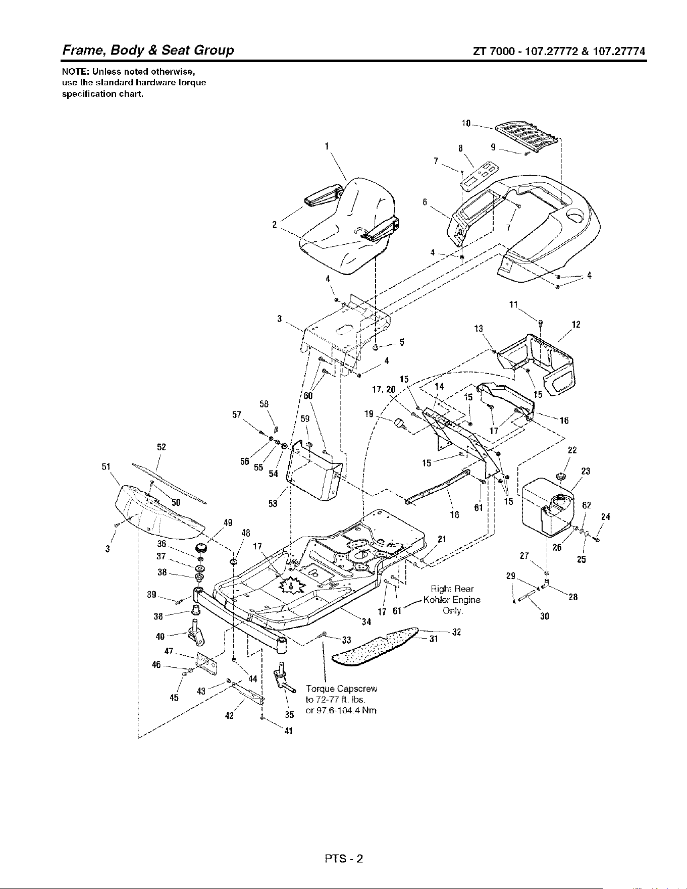
Frame, Body & Seat Group ZT 7000 - 107.27772 & 107.27774
NOTE: Unless noted otherwise,
use the standard hardware torque
specification chart.
1
\
6
51
52
4
\
11
13 \_
58
57
\
53
49
48
/
/
1
Right Rear
_.- Kohier Engine
17 61-- OnJy.
_'34
23
62
Torque Capscrew
to 72-77 ft, Ibs.
/
/ _ or 97.6-104.4 Nm
42 &_. 35
"41
3O
24
PTS - 2

Frame, Body & Seat Group
REF NO PART NO. QTY. DESCRIPTION
1 1726018SM 1
2 1687021SM 1
3 1727332ASM 1
4 1960694SM 12
5 1931648SM 4
6 1734144SM 1
7 1960715SM 8
8 1727699ASM 1
9 1673320SM 3
10 1708504SM 1
11 1960715SM 6
12 1715962ASM 1
13 1673796SM 1
14 1732974ASM 1
14 1727308ASM 1
15 1931277SM 10
16 1727945ASM 1
16 1727682ASM 1
17 1930591SM 12
18 1727810ASM 1
19 1726390SM 2
20 1933689SM 1
21 1933988SM 4
22 1714020SM 1
23 1726397SM 1
24 1930600SM 1
25 1919381SM 3
26 1710437SM 1
27 1726400SM 1
28 1674792SM 1
29 2860112SM 2
30 1726594SM 1
31 1728986SM 1
32 1728987SM 1
33 1920328SM 1
34 1687299SM 1
35 1715999SM 1 ARM, Caster, L.H.
36 2834712SM 2 RING, E-Retaining
37 1919394SM 4 WASHER
38 1721682SM 4 BUSHING
39 1704314SM 2 FITTING, Lube
40 1715997SM 1 ARM, Caster, R.H.
ZT7000-107.27772 & 107.27774
SEAT ASSEMBLY, wth Arm Rests (Includes Ref. No, 68)
ARM REST KIT, (L.H. & R.H.)
SUPPORT, Seat
NUT, Hex Flange ESNA, 1/4-20
CAPSCREW, Hex Head Whiz Lock Dog Point, 5/16-18 x 3/4
DECK, Seat
SCREW, Truss Head Terx Drive, 1/4-20 x 3/4
PLATE, Pod Control
RIVET, Pop
SCREEN, Seat Deck
CAPSCREW, Hex Washer Head Taptite 1/4-20 x 1/2
SHROUD, Rear
SPACER, Powdered Metal (22HP Models Only)
SUPPORT, Seat Deck (20HP Models)
SUPPORT, Seat Deck (22HP Models)
NUT, Hex Flange Whiz Lock, 5/16-18
DUCT, Air Inlet (20HP Models)
DUCT, Air Inlet (22HP Models)
CAPSCREW, Hex Head Whix Lock, 5/16-18 x 3/4, G5
BRACE, Tank
BUMPER, Rubber
CAPSCREW, Hex Head Whiz Lock, 5/16-18 x 1-1/2, G5
NUT, Push
CAP, Fuel Tank
TANK, Fuel
CAPSCREW, Hex Washer Head Taptite, 5/16-18 x 1-1/2
WASHER, 5/16
SPACER
BUSHING, Fuel Tank
ELBOW, with Screen, Gas Tank to Fuel Line
CLAMP, Hose, Wire Type E
HOSE Fuel 11-1/2" Long
PAD, Footrest, R,H.
PAD, Footrest, L,H.
CAPSCREW, Hex Head, 1/2-13 x 1-1/2, G5
FRAME & SPINDLES ASSEMBLY (Includes Ref, Nos. 35, 36, 37, 38, 39 & 40)
Footnotes
PTS-3

Frame, Body & Seat Group ZT 7000 - 107.27772 & 107.27774
NOTE: Unless noted otherwise,
use the standard hardware torque
specification chart.
1
\
6
51
52
4
\
11
13 \_
58
57
\
53
49
48
/
/
1
Right Rear
_.- Kohier Engine
17 61-- OnJy.
_'34
23
62
Torque Capscrew
to 72-77 ft, Ibs.
/
/ _ or 97.6-104.4 Nm
42 &_. 35
"41
3O
24
PTS - 4

Body & Seat Group ZT 7000 - 107.27772 & 107.27774
PART NO. QTY. DESCRIPTION
Frame,
REF NO
41
42
43
44
45
46
47
48
49
5O
51
52
53
54
55
56
57
58
59
60
61
62
1664847SM 3
1726024ASM 1
1960368SM 2
1930641SM 2
1930644SM 1
1709235SM 1
1716064ASM 1
1960518SM 2
1726504SM 2
1931317SM 2
1726025ZSM 1
1726306SM 1
1727685ASM 1
1704626SM 2
1705249SM 2
1705248SM 2
1704628SM 2
1960373SM 2
1935255SM 4
1960295SM 6
1930595SM 1
2820427SM 1
SCREW, Hex Washer Head Taptite, 5/16-18 x 3/4
BRACKET, Footrest Support
NUT, Speed Lug Type, 1/4-20
NUT, Hex Flange Whiz Lock, 1/4-20
NUT, Hex Flange Two-Way Lock, 1/2-13
SPACER
HOOK & WASHER ASSEMBLY
NUT, Push, 1/4
CAP, Hub
CARRIAGE BOLT, 1/4-20 x 3/4
PANEL, Footrest
PAD, Footrest, Front
PANEL, Front
SPACER
SPACER
PIVOT, Hood
PIN, Quick
CAPSCREW, Hex Washer Head Taptite, 5/16-18 x 1
NUT, Speed Lug Type, 5/16-18
SCREW, Hex Flange Whiz Lock, 1/4-20 x 5/8
CAPSCREW, Hex Flange Whiz Lock, 5/16-18 x 1-1/4, G5 (20HP Models Only)
LOCKWASHER, External Tooth, 3/8
Footnotes
PTS - 5
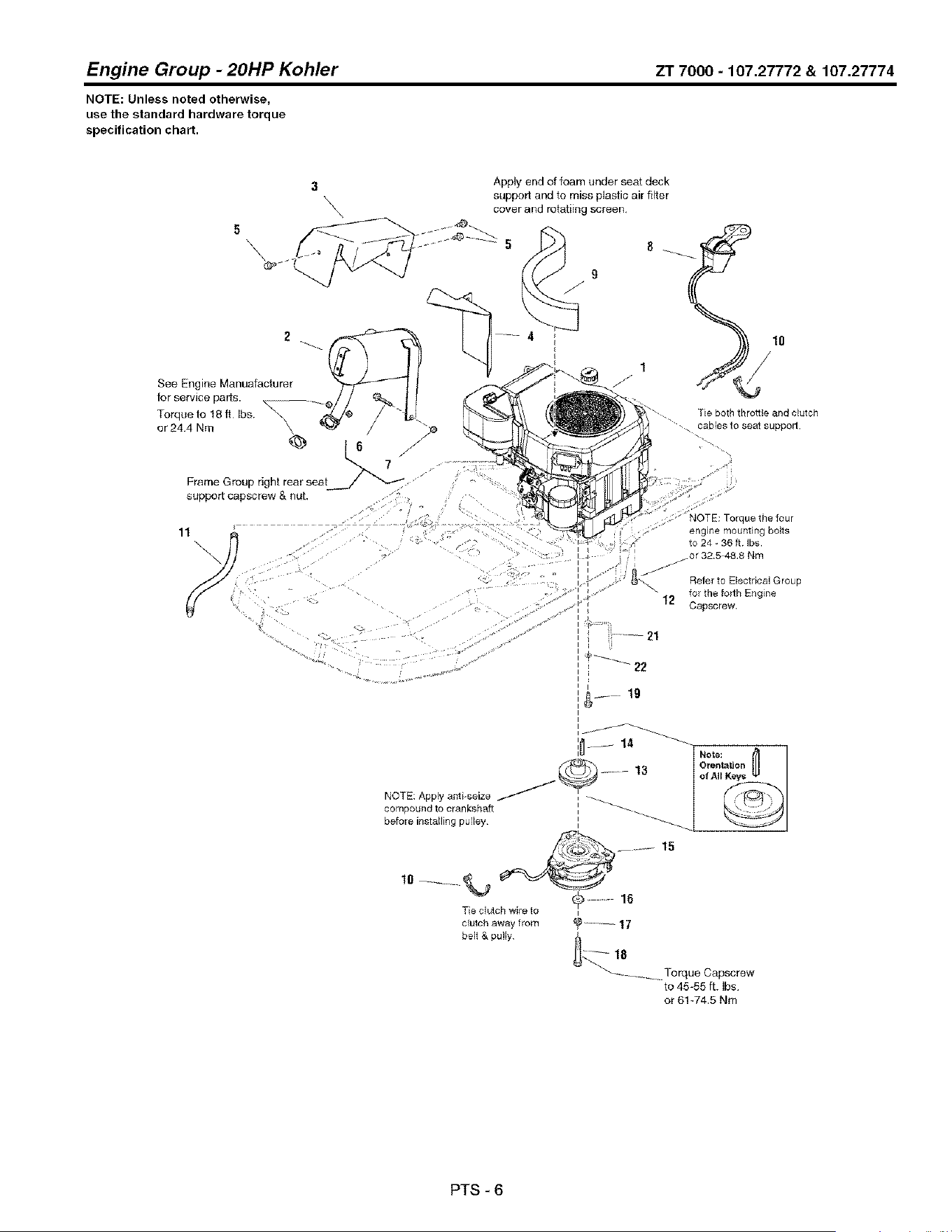
Engine Group - 20HP Kohler ZT 7000 - 107.27772 & 107.27774
NOTE: Unless noted otherwise,
use the standard hardware torque
specification chart.
5
\
support capscrew & nut,
3 Apply end of foam under seat deck
support and to miss plastic air filter
\ cover and rotatiing screen,
9
,J
Tie both throttle and clutch
cables to seat support
11
/
NOTE: Apply anti-seize
compoutld to crankshaft
before installing pulley
engine mout_ting bolts
to 24 - 36 ft Ibs
.or 32,5 48,8 Nm
Refer to Electrica! Group
for the forth Et_gine
12 Capscrew
i ..... 21
i 22
Tie clutch were to
clutch away from
belt & pu
Engine Group - 20HP Kohler
REF NO PART NO, QTY,
1 1
2 1727809SM 1
3 1728982SM 1
4 1727937ASM 1
5 1924856SM 1
6 1930595SM 1
7 1931277SM 2
8 1727817SM 1
9 1727928SM 1
10 2832747SM 1
11 1726498SM 1
12 2860361SM 4
13 1727816SM 1
14 1720463SM 1
15 1686880SM 1
16 1708264SM 1
17 1918199SM 1
18 1960648SM 1
19 1923683SM 3
21 1734049SM 1
22 1924940SM 1 WASHER, 3/8
ZT7000-107.27772 & 107.27774
DESCRIPTION
ENGINE, 20HP, KOHLER Courage, Model #SV600S, Type # 0010
MUFFLER
SHIELD & INSULATION ASSEMBLY, Muffler, Heat Top
SHIELD, Muffler, Heat Side
CAPSCREW, Hex Head, 5/16-18 x 1/2, G5
CAPSCREW, Hex Flange Whiz Lock, 5/16-18 x 1-1/4, G5
NUT, Hex Flange, 5/16-18
CONTROL, Throttle
SEAL, Foam
TIE, Self Locking
HOSE, Oil Drain
CAPSCREW, Hex Washer Head Taptite, 3/8-16 x 2
PULLEY
KEY, Parallel
CLUTCH, Electric, OGURA
WASHER, Hex
LOCKWASHER, Spring
CAPSCREW, Hex Head, 7/16-20 x 2-3/4, G5
CAPSCREW, Hex Washer Head Taptite, 3/8-16 x 3/4
ANCHOR, Clutch
Footnotes
Note* See Engine Repair Pa_s.
PTS - 7
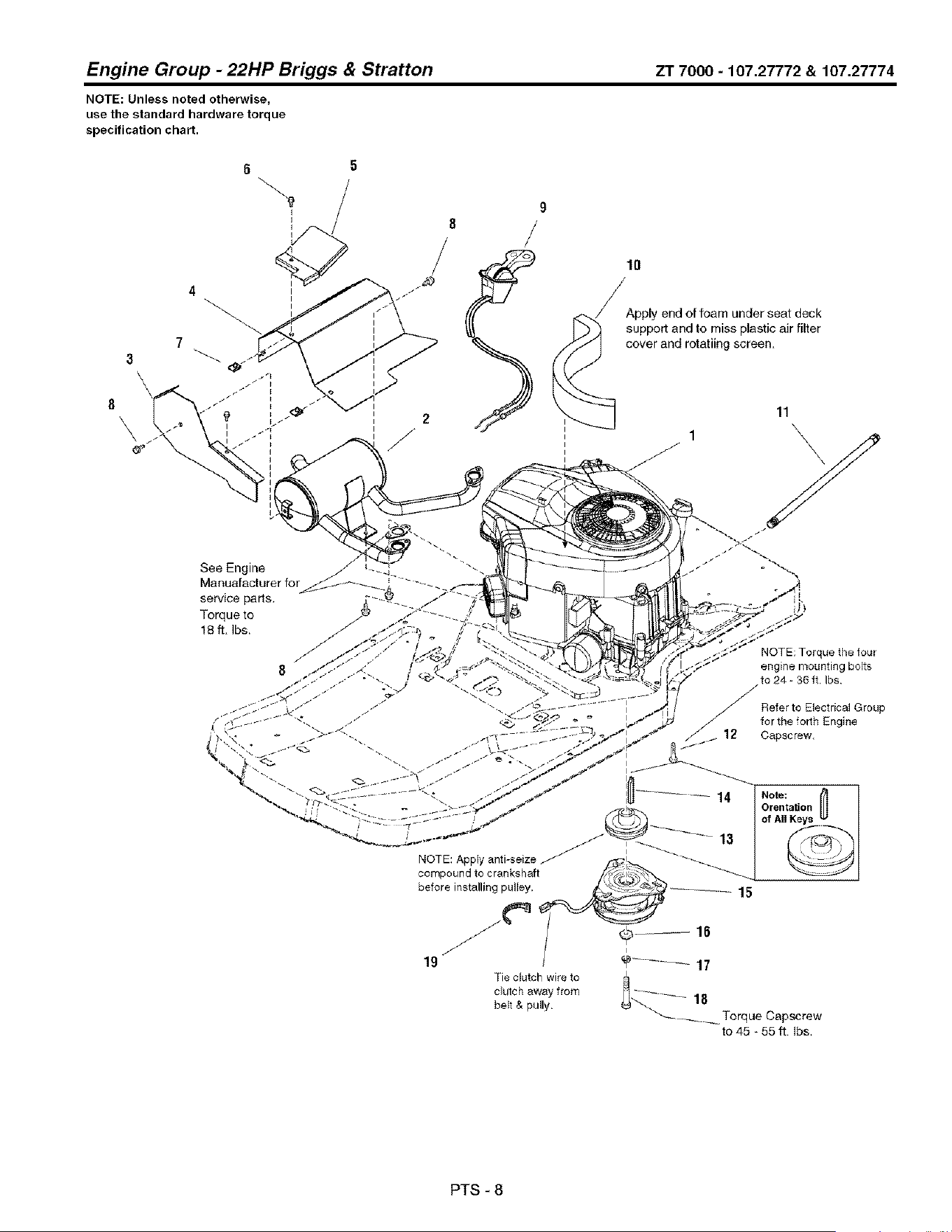
Engine Group - 22HP Briggs & Stratton ZT 7000 - 107.27772 & 107.27774
NOTE: Unless noted otherwise,
use the standard hardware torque
specification chart.
9
8
I
10
._.,_!Apply end of foam under seat deck
support and to miss plastic air filter
cover and rotatiing screen,
11
\
NOTE: Torque the tour
engine mounting bolts
/,to 24 - 36 ft Ibs
Refer to Bectrical Group
// for the forth Englne
12 Capsc rew
PTS - 8
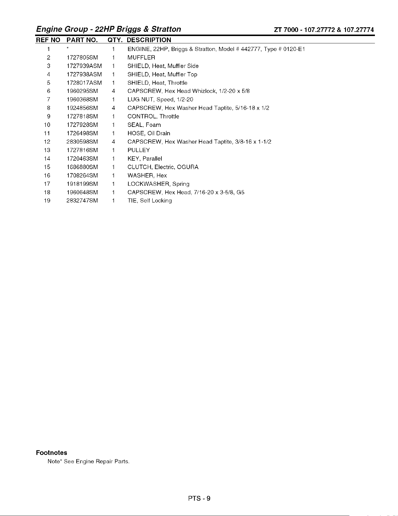
Engine Group - 22HP Briggs & Stratton ZT 7000 - 107.27772 & 107.27774
REF NO PART NO, QTY, DESCRIPTION
1
2 1727805SM
3 1727939ASM
4 1727938ASM
5 1728017ASM
6 1960295SM
7 1960368SM
8 1924856SM
9 1727818SM
10 1727928SM
11 1726498SM
12 2830598SM
13 1727816SM
14 1720463SM
15 1686880SM
16 1708264SM
17 1918199SM
18 1960648SM
19 2832747SM
1 ENGINE, 22HP, Briggs & Stratton, Model # 442777, Type # 0120-E1
1 MUFFLER
1 SHIELD, Heat, Muffler Side
1 SHIELD, Heat, Muffler Top
1 SHIELD, Heat, Throttle
4 CAPSCREW, Hex Head Whizlock, 1/2-20 x 5/8
1 LUG NUT, Speed, 1/2-20
4 CAPSCREW, Hex Washer Head Taptite, 5/16-18 x 1/2
1 CONTROL, Throttle
1 SEAL, Foam
1 HOSE, Oil Drain
4 CAPSCREW, Hex Washer Head Taptite, 3/8-16 x 1-1/2
1 PULLEY
1 KEY, Parallel
1 CLUTCH, Electric, OGURA
1 WASHER, Hex
1 LOCKWASHER, Spring
1 CAPSCREW, Hex Head, 7/16-20 x 3-5/8, G5
1 TIE, Self Locking
Footnotes
Note* See Engine Repair Pa_s.
PTS - 9
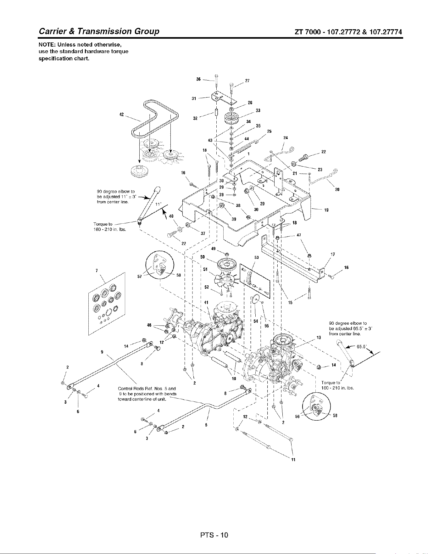
Carrier & Transmission Group ZT 7000 - 107.27772 & 107.27774
NOTE: Unless noted otherwise,
use the standard hardware torque
specification chart.
27
42
32
24
90 degree elbow to
from cel_ter _ine
Torque to /_t
160- 210 in Ibs
16
\
\
f
20
19
Q 4
6
I I I
I
r i "_
i i
I i
\ z
Control Rods Ref. Nos 5 and
9 to be positioned with bends
toward centerline of unit. ------
52
41
10
8 / I
f
i
I
I
!1
90 degree elbow to
be adiusted 65 5" ± 3
f_om oer_ter lirle
./13
\x
". I
Torque to
I 160-210in Ibs
PTS-IO

Carrier & Transmission Group ZT 7000 - 107.27772 & 107.27774
REFNO PARTNO.
1 1960251SM
2 1960666SM
3 1960236SM
4 1960223SM
5 1727555SM
6 1919381SM
7 1728060SM
8 1727831SM
9 1727556SM
10 1727795ASM
11 2860398SM
12 1918267SM
13 1727806SM
14 1930650SM
15 2860358SM
16 1960268SM
17 1727464A
18 1923141SM
19 1732595ASM
20 1727767SM
21 1725550SM
22 1921176SM
23 1719725SM
24 1727766SM
28 1730177SM
26 1667811SM
27 1922130SM
28 1917372SM
29 1917356SM
30 1919326SM
31 1715971ASM
32 1713588SM
33 2154534SM
34 1916965SM
35 1916950SM
36 1921719SM
37 1719683SM
38 1928352SM
39 1930644SM
40 1924361SM
41 1727807SM
42 1687316SM
43 1924940SM
44 2108717SM
QTY. DESCRIPTION
1 NUT, Hex Centerlock Jam, 3/8-16
6 NUT, Hex Flange, 5/16-18 ESNA
2 SPACER
2 CARRIAGE BOLT, 5/16-16 x 1, G5
1 ROD, Control, L.H.
1 WASHER, 5/16
1 HYDRO SEAL KIT
2 BOLT, Shoulder, 7/16-14, G5
1 ROD, Control, R.H.
2 SPACER
2 CAPSCREW, Hex Head, 7/16-14 x 8, G5
4 WASHER, 7/16
1 TRANSMISSION, Hydro Gear, LH.
2 NUT, Hex Flange, 7/16-14, Two-Way Lock
4 SCREW, Hex Washer Head Taptite, 3/8-16 x 2-1/2
2 CARRIAGE BOLT, 3/8-16 x 1-1/4, G5
1 SUPPORT, Center Transmission
4 CAPSCREW, Hex Head, 5/16-18 x 2-3/4, G5
1 FRAME ASSEMBLY, Carrier Transmission
1 ROD, Actuator, R.H. E-Coat
1 CLIP, Rod End Clevis L.H.
2 CAPSCREW, Hex Head, 1/2-13 x 1-1/4, G5
1 SPACER
1 ROD, Actuator, L.H. E-Coat
1 SPRING, Extension
1 SPACER, Powdered Metal
1 CAPSCREW, Hex Head, 3/8-16 x 2-1/4, G5
1 NUT, Hex, 5/16-18
1 LOCKWASHER, Spring 5/16
1 WASHER, 5/16
1 ARM, Idler
1 SPACER, Powdered Metal
1 PULLEY, Idler
1 LOCKWASHER, Spring, 3/8
1 NUT, Hex, 3/8-16
1 CAPSCREW, Hex Head, 5/16-18 x 2-1/2, G5
1 SPACER
1 NUT, Hex Flange, 3/8-16, Whiz Lock
2 NUT, Hex Flange, 1/2-13, Two-Way Lock
2 WASHER, 1/2
1 TRANSMISSION, Hydro Gear, R.H.
1 V-BELT
3 WASHER, 3/8
1 SPACER
Footnotes
PTS - 11

Carrier & Transmission Group ZT 7000 - 107.27772 & 107.27774
NOTE: Unless noted otherwise,
use the standard hardware torque
specification chart.
27
42
32
24
90 degree elbow to
from cel_ter _ine
Torque to /_t
160- 210 in Ibs
16
\
\
f
20
19
Q 4
6
I I I
I
r i "_
i i
I i
\ z
Control Rods Ref. Nos 5 and
9 to be positioned with bends
toward centerline of unit. ------
52
41
10
8 / I
f
i
I
I
!1
17
I
/ 16
J
90 degree elbow to
be adiusted 65 5" ± 3
f_om oer_ter lirle
J 13
\x
". I
Torque to
I 160-210in Ibs
PTS-12
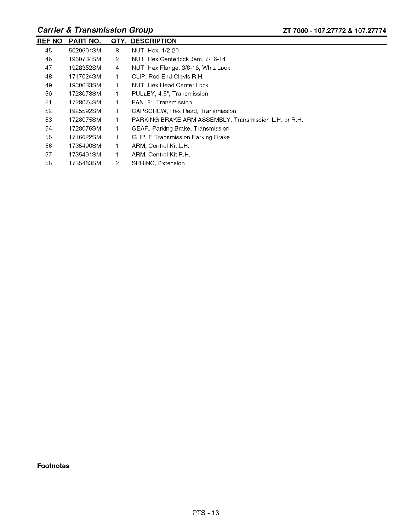
Carrier & Transmission Group ZT 7000 - 107.27772 & 107.27774
REF NO
45
46
47
48
49
50
51
52
53
54
55
56
57
58
PART NO.
5020601SM
1960734SM
1928352SM
1717024SM
1930633SM
1728073SM
1728074SM
1925592SM
1728075SM
1728076SM
1716622SM
1735490SM
1735491SM
1735483SM
QTY. DESCRIPTION
8 NUT, Hex, 1/2-20
2 NUT, Hex Centerlock Jam, 7/16-14
4 NUT, Hex Flange, 3/8-16, Whiz Lock
1 CLIP, Rod End Clevis R.H,
1 NUT, Hex Head Center Lock
1 PULLEY, 4,5", Transmission
1 FAN, 6", Transmission
1 CAPSCREW, Hex Head, Transmission
1 PARKING BRAKE ARM ASSEMBLY, Transmission L.H, or R.H,
1 GEAR, Parking Brake, Transmission
1 CLIP, E Transmission Parking Brake
1 ARM, Control Kit L,H.
1 ARM, Control Kit R.H,
2 SPRING, Extension
Footnotes
PTS - 13

Controls Group ZT 7000 - 107.27772 & 107.27774
NOTE: Unless noted otherwise,
use the standard hardware torque
specification chart.
6 _12 Ibs inwardforce measured
1. / t" above bottom of foam gripe
(both sides).
42
Handlebarsout (locked) compress
brakespring to 3" length
Brakearm to beful!
in gearteeth,
4O
47
5
35
14
33
6
I
i 21
27
25 29
2O
7 - "
27 16
_4
31
25
48 20
43
22
45
28
/
12
11
21
7
PTS - 14

Controls Group
REFNO PARTNO.
1 1725927SM
2 1960027SM
3 1703805SM
4 1921977SM
5 1920161SM
6 1960717SM
7 1960686SM
8 172800gASM
9 1727919SM
10 1727663ASM
11 1931335SM
12 1931338SM
13 1727926ASM
14 1917356SM
15 1960086SM
16 1919381SM
17 1720452SM
18 1727796ASM
19 1726410SM
20 1727933ASM
21 1960223SM
22 1921221SM
23 1727918SM
26 1919438SM
26 1919326SM
27 1666697SM
28 1960723SM
29 1931277SM
31 1727603ASM
32 1728010ASM
33 1727927ASM
34 1716025SM
35 1701342SM
36 1726839SM
37 1666106SM
38 1727667SM
39 1922127SM
40 1722460SM
41 192131gSM
42 1727669SM
43 1733357SM
44 1709314SM
45 1727814ASM
46 1729277SM
QTY. DESCRIPTION
1 SHAFT, Cross
2 WASHER, 1/2
2 RING, Klipring Extension
5 CAPSCREW, Hex Head, 5/16-18 x 1-1/4, G5
6 NUT, Hex Jam, 5/16-18
2 NUT, Speed, 5/16-18 Lug Type
16 NUT, Hex Flange, 5/16-18 ESNA
1 BRACKET, L.H. Mounting Handle Pivot
2 CLIP, Brake
2 BRACKET, "L" Switch
2 CARRIAGE BOLT, 5/16-18 x 1 G5
2 CARRIAGE BOLT, 5/16-18 x 1-3/4, G5
1 BRACKET, Tube Mount L.H.
4 LOCKWASHER, Spring, 5/16
4 SCREW, Truss Head Terx Drive, 5/16-18 x 7/8
6 WASHER, 5/16
2 CLAMP, Saddle Snow Handle, E-Coat
2 TUBE, Handle
2 GRIP, Foam Handle
2 COVER, Lower Handle
6 BOLT, Carriage, 6/16 - 18 x 1-1/4
4 CAPSCREW, Hex Head, 5/16-18 x 1-1/2, G5
2 SHOCK ABSORBER
4 NUT, Hex Lock ESNA Light, 5/16-18NC-3B
1 WASHER, 5/16
4 SPACER, Powdered Metal
2 CARRIAGE BOLT, 5/16-18 x 2-1/4, G5
8 NUT, Hex Flange Whiz Lock, 6/16-18
2 PIVOT ASSEMBLY, Control
1 BRACKET, R.H. Mounting Handle Pivot
1 BRACKET, Tube Mount R,H.
4 BUSHING
1 SPRING, Compression (Early Models)
1 KNOB Extension Thread, 5/16-18 x 1-1/4
1 BUSHING, Powdered Metal
1 BRACKET, Pivot
1 CAPSCREW, Hex Head 5/16-18 x 1-3/4, G6
4 PIN, Quick
2 WASHER 1/4
1 ROD, Pivot
1 ROD, 1/4-20 x 2
1 SPRING, Extension
1 BRACKET, Duel Brake
1 SPRING, Compression
ZT7000-107.27772 & 107.27774
Footnotes
PTS-15
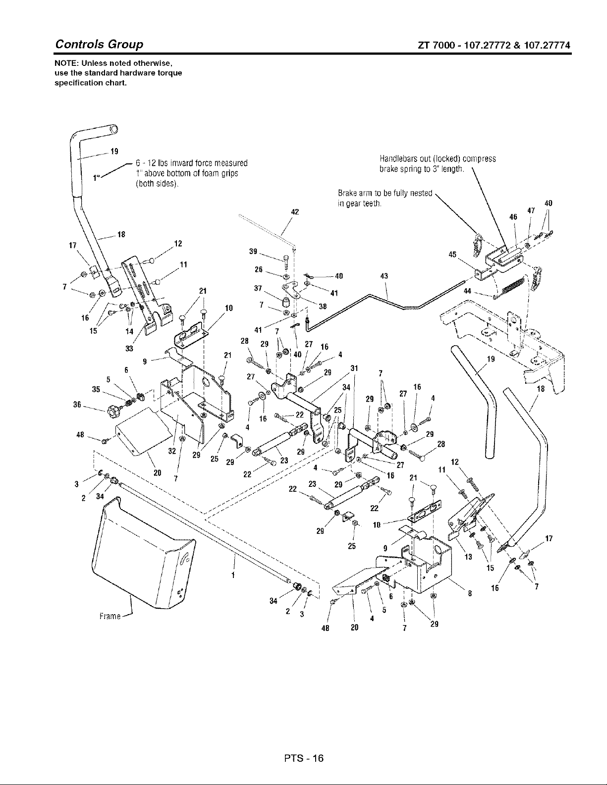
Controls Group ZT 7000 - 107.27772 & 107.27774
NOTE: Unless noted otherwise,
use the standard hardware torque
specification chart.
6 _12 Ibs inwardforce measured
1. / t" above bottom of foam gripe
(both sides).
42
Handlebarsout (locked) compress
brakespring to 3" length
Brakearm to beful!
in gearteeth,
4O
47
5
35
14
33
6
I
i 21
27
25 29
2O
7 - "
27 16
_4
31
25
48 20
43
22
45
28
/
12
11
21
7
PTS-16

Controls Group
REF NO PART NO,
47 1960694SM
48 1925003SM
QTY. DESCRIPTION
1 NUT, Hex Flange, 1/4-20 ESNA
2 SCREW, Hex Washer Head Taptite, 1/4-20 x 1/2
ZT7000-107.27772 & 107.27774
Footnotes
PTS-17
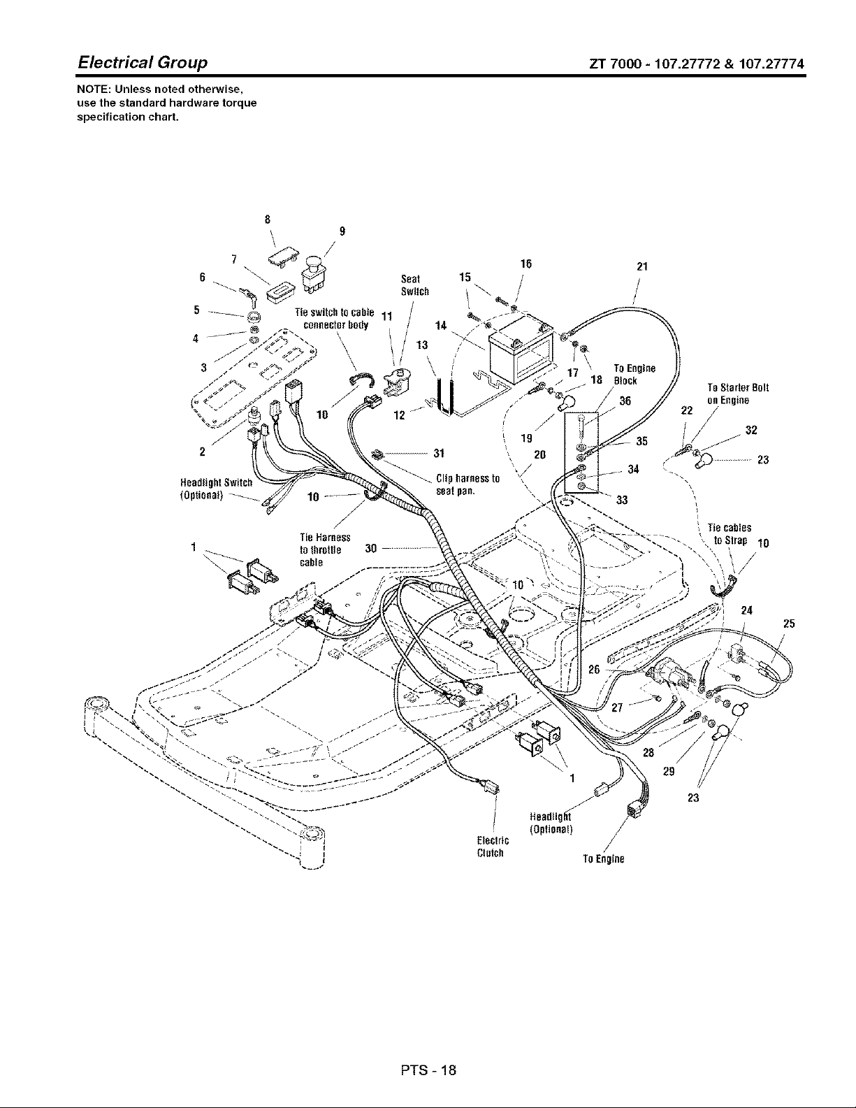
Electrical Group ZT 7000 - 107.27772 & 107.27774
NOTE: Unless noted otherwise,
use the standard hardware torque
specification chart.
8
9
5 .--__ _ Tieswitchlocabte 11
connector bogy
4
= \
TieHarness
1
Sent
Swllch
14
/
13
',/\
16
15
21
/
TOStarter8nit
on Engine
22
32
35
23
Headlight
(Optional)
Electric
CInlch TOEngine
29
23
24
25
PTS - 18

Electrical Group
REFNO PARTNO.
1 1732006SM
2 1686734SM
3 1960547SM
4 1717549SM
5 1717550SM
6 1717163SM
7 1731185SM
8 1722611SM
9 1722887SM
10 1701011SM
11 1732005SM
12 1667805SM
13 1665872SM
14 .....
15 2823341SM
16 2821319SM
17 2816964SM
18 2816622SM
19 1709086SM
20 171654gSM
21 1707056SM
21 1713163SM
22 1727668SM
23 1724588SM
24 1665238SM
25 1665237SM
26 1686981SM
27 1925003SM
28 2820426SM
29 2820263SM
30 1727801SM
31 2172434SM
32 1917421SM
33 1931277SM
34 2820427SM
35 1919326SM
36 1921221SM
36 1921978SM
ZT7000-107.27772 & 107.27774
QTY. DESCRIPTION
4 SWITCH, Push Button
1 SWITCH ASSEMBLY, Ignition (includes Ref. Nos. 3, 4, 5 & 6)
1 LOCKWASHER, Internal Tooth, Ignition Switch
1 NUT, Hex Flange, 5/8-32, Ignition Switch
1 COVER, Ignition Switch
1 KEYS (Set of Two Keys)
1 METER, Hour Digital with Oil & Lube Alarms
1 PLUG, Hole
1 SWITCH, PTO Push/Pull
4 TIE, Self Locking
1 SWITCH, Push Button, Seat Switch
1 BRACE, Battery
1 STRAP, Black
1 BATTERY, 12 Volt, 6 Cell, 340 Amps
2 CAPSCREW, Hex Head 1/4-20 x 3/4, G5
2 WASHER, 1/4
2 LOCKWASHER, Spring, 1/4
2 NUT, Hex, 1/4-20
1 BOOT, Insulator
1 CABLE, #6 x 1O, 2 Ring Terminals
1 CABLE, #6 x 15, 2 Ring Terminals (Briggs & Stratton)
1 CABLE, #6 x 26, 2 Ring Terminals (KOHLER)
1 CABLE, #6 x 15, 2 Ring Terminals
3 COVER, Terminal
1 BREAKER, Circuit, 12 Volt, 20 Amps with Tab
1 WIRE, 12GA
1 SOLENOID, 4 Pole, 12 Volt DC
2 CAPSCREW, Hex Washer Head Taptite, 1/4-20 x 1/2, G5
2 LOCKWASHER, External Tooth
2 NUT, Hex, 5/16-24
1 HARNESS, Wiring
1 CLIP Cable
1 NUT, Hex 3/8-16NC-2B
1 NUT, Hex Flange Whiz Lock 3/8-18
1 WASHER, External Tooth, 3/8
2 WASHER, 5/16
2 CAPSCREW, Hex Head 5/16-18 x 1-1/2, G5 (Briggs & Stratton)
2 CAPSCREW, Hex Head 5/16-18 x 2 G5 (KOHLER)
Footnotes
PTS-19
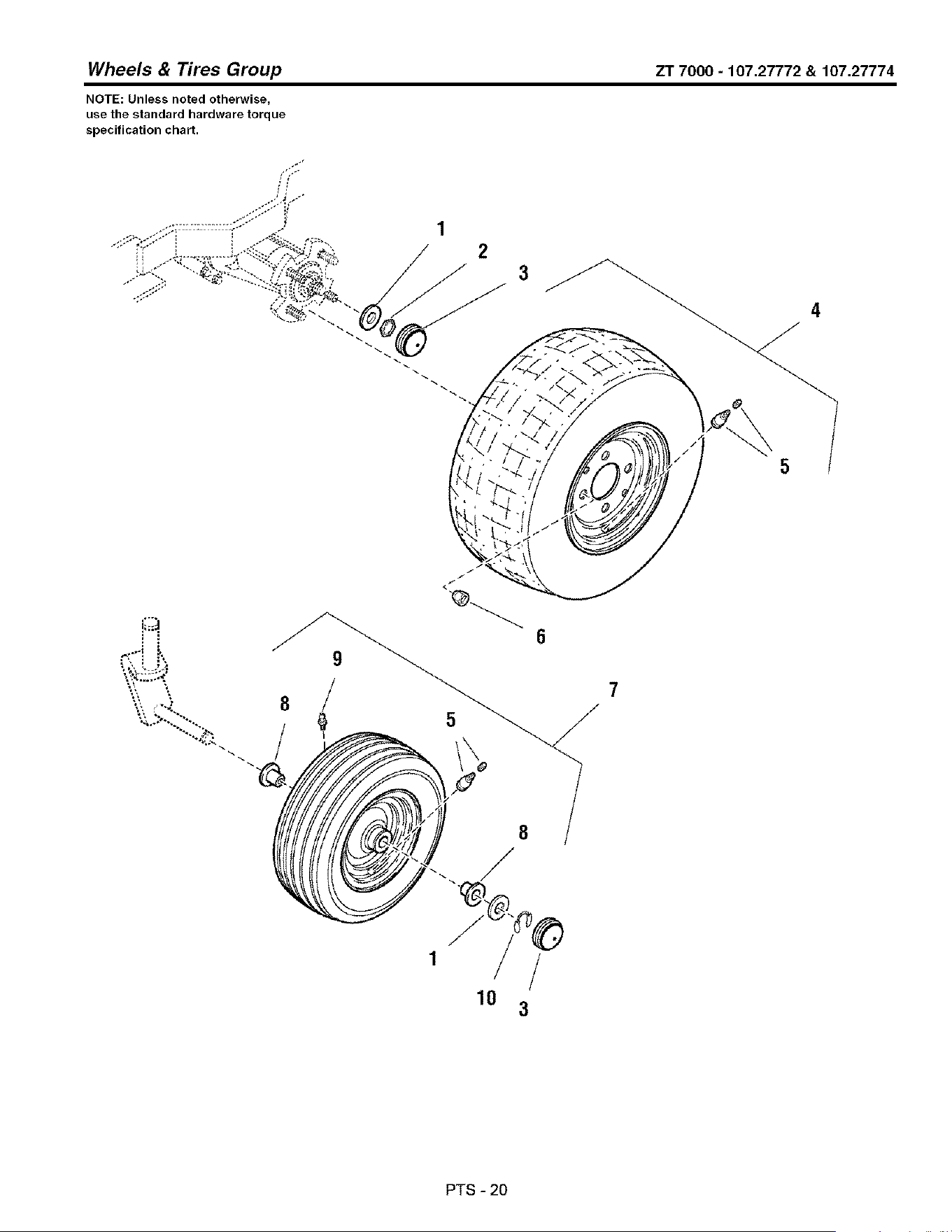
Wheels & Tires Group ZT 7000 - 107.27772 & 107.27774
NOTE: Unless noted otherwise,
use the standard hardware torque
specification chart.
3
.'1
8
/
8
/
1 /
10
3
PTS-20

Wheels & Tires Group
REFNO PARTNO,
1 2860202SM 4
2 2830647SM 2
3 1722675SM 4
4 1726383SM 2
5 2172353SM 2
6 5020601SM 8
7 1726382SM 2
8 1713167SM 4
9 2812808SM 2
10 1611710SM 2
QTY. DESCRIPTION
WASHER, 3/4
NUT, Hex Lock PAL, 3/4-20
CAP, Hub
WHEEL & TIRE ASSEMBLY, Rear
VALVE STEM & CAP
NUT, Hex Lug, 1/2-20
WHEEL & TIRE ASSEMBLY, Front
BUSHING, Wheel
FITTING, Lube
RING, Klipring for 3/4 Shaft
ZT7000-107.27772 & 107.27774
Footnotes
PTS - 21
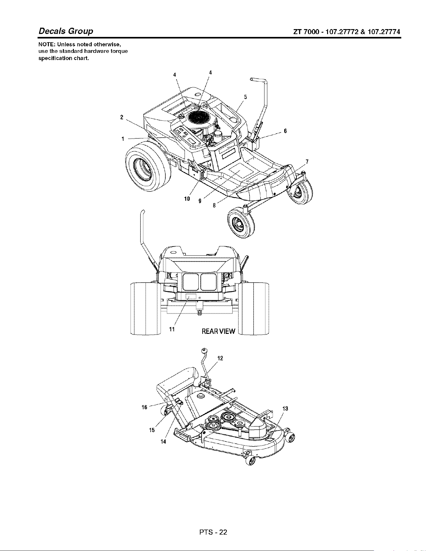
Decals Group ZT 7000 - 107.27772 & 107.27774
NOTE: Unless noted otherwise,
use the standard hardware torque
specification chart.
2
4
/
5
10 9 J
__ 11 REARVIEW
116
PTS-22

Decals Group
REFNO PARTNO.
1 1726526SM
2 1728046SM
3
4 1726631SM
5 1728045SM
6 1727858SM
6 1727857SM
7 1728049SM
8 1727855SM
9 1727856SM
10 1726638SM
11 1720543SM
12 1726642SM
13 1704276SM
14
15 1722789SM
15 1722790SM
16 1704277SM
ZT7000-107.27772 & 107.27774
QTY.
1
1
1
1
1
1
1
1
1
1
1
2
1
1
1
1
1
1
DESCRIPTION
DECAL Ignition Switch
DECAL. Seat Deck Stripe, R.H.
DECAL Engine 18HP Kohler
DECAL Do Not Remove Foam Seal
DECAL Seat Deck Stripe, L,H.
DECAL ZT 7000 (2044)
DECAL ZT 7000 (2250)
DECAL. CRAFTSMAN
DECAL Panel Upper, Operation
DECAL Panel Lower, Warning/Danger & Icon Indicator
DECAL Tracking
DECAL Transmission Release Valve
DECAL, Height of Cut
DECAL, Danger (Do Not Put Hands/Feet in Mower)
DECAL, OPEl Certified (Not Serviced)
DECAL, 44" Mower Deck
DECAL, 50" Mower Deck
DECAL, Danger (Do Not Operate With Out Deflector)
Footnotes
Note* Not a Service Part.
PTS-23
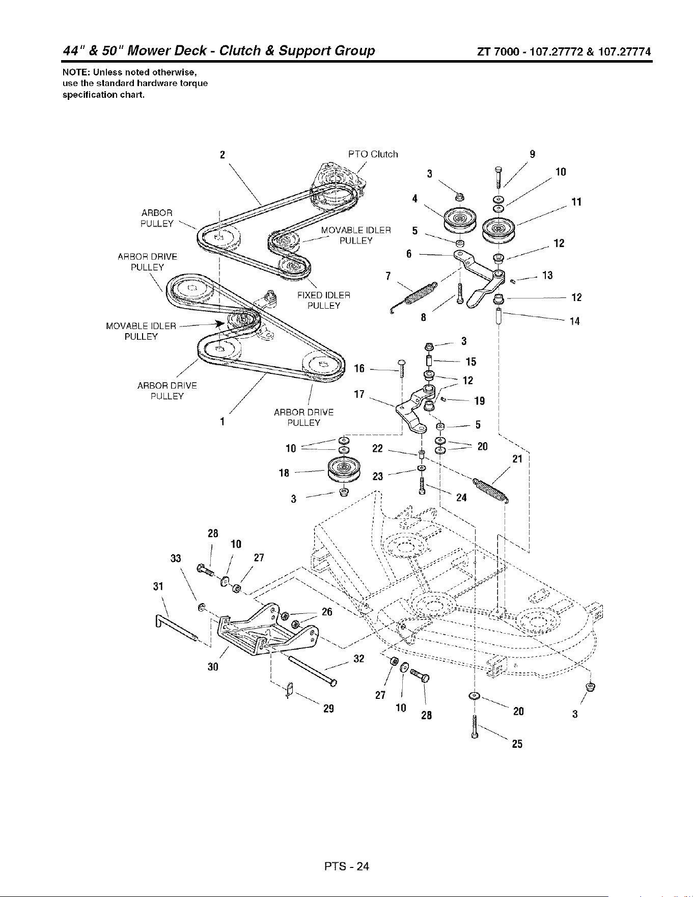
44" & 50" Mower Deck - Clutch & Support Group ZT 7000 - 107.27772 & 107.27774
NOTE: Unless noted otherwise,
use the standard hardware torque
specification chart.
25
PTS - 24

44" & 50" Mower Deck -
REF NO PART NO. QTY.
1 1727869SM 1
1 1726472SM 1
2 1727773SM 1
2 1726471SM 1
3 196033gSM 4
4 2171247SM 1
5 1667811SM 2
6 1726814SM 1
7 1714062SM 1
8 1931353SM 1
9 1922918SM 1
10 1924940SM 7
11 1706510SM 1
12 1676148SM 4
13 2812808SM 1
14 1657242SM 1
15 1674669SM 1
16 1960268SM 1
17 1718561SM 1
18 1724387SM 1
19 2821133SM 1
20 1924356SM 3
21 1656936SM 1
22 170115gSM 1
23 192131gSM 1
24 1933958SM 1
25 1921972SM 1
26 191943gSM 2
27 1713791SM 2
28 1922605SM 2
29 2176012SM 1
30 1728124ASM 1
31 1726012SM 1
32 1713578SM 1
33 196051gSM 1
Clutch & Support Group
DESCRIPTION
V-BELT, 44 '_Mower Deck
V-BELT, Mower Drive, 50" Mower Deck
V-BELT, P.T.O. 44" Mower Deck
V-BELT, P.T.O. 50" Mower Deck
NUT, Hex Flange, 3/8-16
PULLEY, Idler
SPACER, Powdered Metal
LEVER & HANDLE ASSEMBLY (includes Ref. Nos. 12 & 13)
SPRING Extension
CAPSCREW, 3/8-16 x 1-1/2, G5
CAPSCREW, 3/8-16 x 3-1/4
WASHER, 3/8
PULLEY, Idler
BUSHING
FITTING, Lube, 1/4-20 Tapered
SPACER, Hardened
SPACER, Hard Case
CARRIAGE BOLT, 3/8-16 x 1-1/4, G5
LEVER ASSEMBLY, Idler (Includes Ref. Nos. 12 & 19)
PULLEY, Idler
FITTING, Lube, 1/4 Drive
WASHER, 3/8
SPRING, Extension
SPACER
WASHER, 1/4
CAPSCREW, Hex Head, 1/4-20 x 1-1/6
CAPSCREW, Hex Head, 3/8-16 x 2-1/2, G5
NUT, Hex Lock ESNA Light, 3/8-16
SPACER, Powdered Metal
CAPSCREW, 3/8-16 x 1-1/4, G8
PIN, Retaining
HITCH
ROD, Hitch
ROD, Hitch, 1/2 x 7-5/8
NUT, Push 1/2
ZT 7000 - 107.27772 & 107.27774
Footnotes
PTS - 25
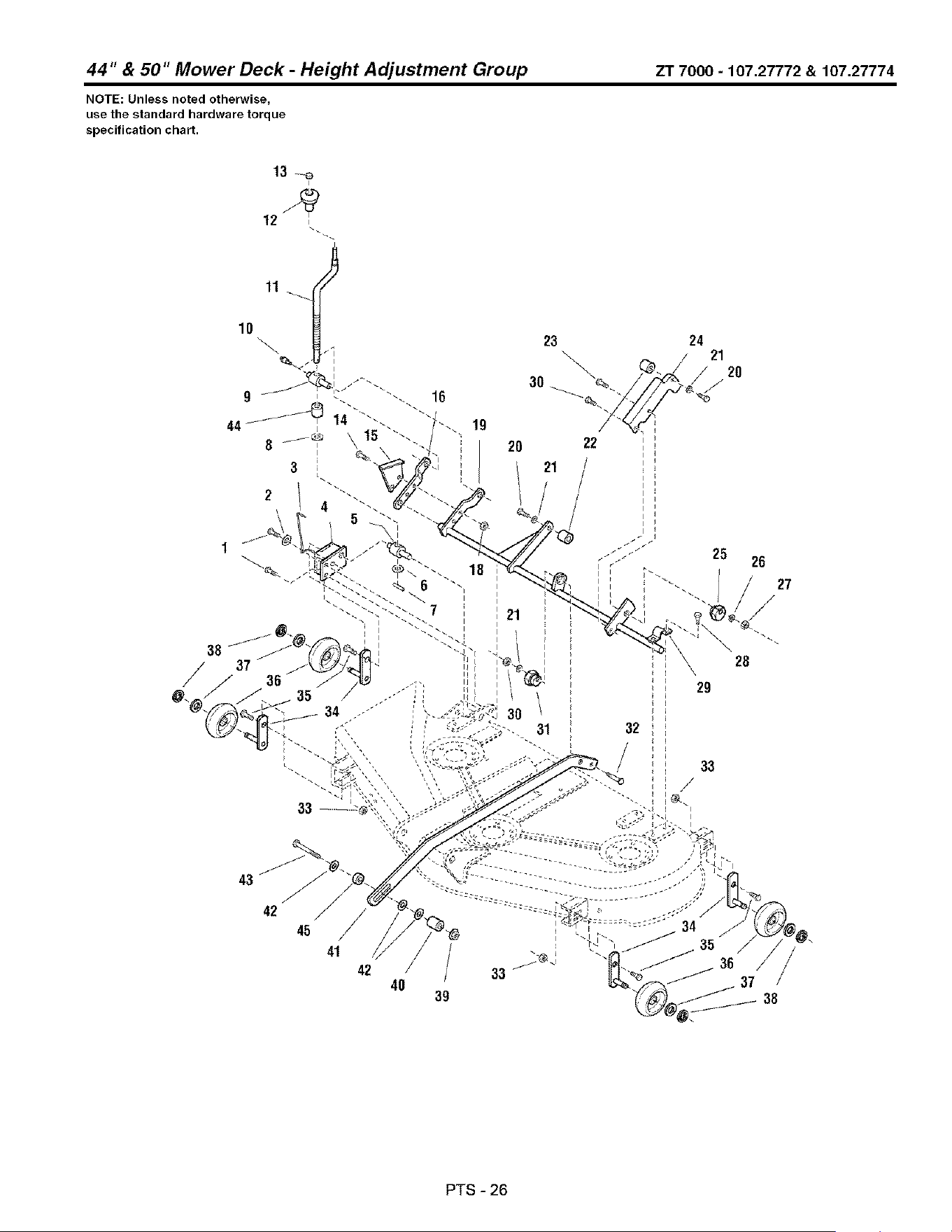
44" & 50" Mower Deck - Height Adjustment Group ZT 7000 - 107.27772 & 107.27774
NOTE: Unless noted otherwise,
use the standard hardware torque
specification chart.
23
\
30_
19
_ 2o
_ 21
33
22
43
42 /
45
41
42
24
21
2O
/-
28
/
40
29
32
PTS - 26

44" & 50" Mower Deck -
REF NO PART NO. QTY.
1 1931202SM 2
2 1919381SM 1
3 1704114SM 1
4 1726424ASM 1
5 1724009SM 1
6 1704097SM 1
7 2816001SM 1
8 1960170SM 2
9 1716892SM 1
10 1704314SM 1
11 1727681SM 1
12 1714084SM 1
13 1960093SM 1
14 1921977SM 2
15 1704116ASM 1
16 1726409ASM 1
18 1931277SM 1
19 1727906ASM 1
19 1727768ASM 1
20 1921210SM 2
21 1916965SM 2
22 1716010SM 2
23 1960655SM 1
24 1718136ASM 1
26 1714879SM 1
26 1924874SM 1
27 2860643SM 1
28 1664847SM 6
29 1665374SM 3
30 1916950SM 1
31 1704082SM 1
32 2118053SM 1
33 1930642SM 4
34 1716020ASM 4
35 1923341SM 4
36 1714760SM 4
37 1960027SM 4
38 2168399SM 4
39 1930645SM 1
40 1674440SM 1
41 1718109A 1
41 1727917ASM 1
42 1922755SM 1
43 1923701SM 1
Height Adjustment Group ZT 7000 - 107.27772 & 107.27774
DESCRIPTION
CAPSCREW, Hex Washer Head Taptite, 5/16-18 x 1-1/4
WASHER, 5/16
ROD, Indicator Height of Cut
PLATE & BRACKET ASSEMBLY, Gauge Wheel
TRUNNION, 1-1/4
WASHER, Detent
PIN, Spring
WASHER, 9/16
TRUNNION, 1-1/4
FITTING, Lube
CRANK Height Adjustment
KNOB Spinner, Soft
NUT, Push
CAPSCREW, Hex Head 5/16-18 x 1-1/4 G6
BRACKET, Height of Cut
ARM Rear
NUT, Hex Whiz Lock, 5/16-18
ARM ASSEMBLY, Roller Bar 50"
ARM ASSEMBLY, Roller Bar 44"
CAPSCREW, Hex Head, 3/8-16 x 1, G6
LOCKWASHER, Spring, 3/8
SPACER, Support
CARRIAGE BOLT, 5/16-18 x 1-1/4, G6
ARM, Rear Adjustable
CAM, Eccentric, Hex
WASHER, 5/16
NUT, Hex Flange Collar Lock, 5/16-18
CAPSCREW, Hex Washer Head Taptite, 5/16-18 x 3/4
STRAP, Arm Assembly
NUT, Hex 3/8-16
CAM, Eccentric
PIN, Round Head, Drilled, 3/8 x 2
NUT, Hex Flange Toplock 1/4-20
SHAFT & BAR ASSEMBLY, Roller Fixed Arm
CAPSCREW, Hex Head 1/4-20 x 3/4, G6
WHEEL, Roller
WASHER 1/2
E-RING, Retaining Extension
NUT, Hex Two-Way Lock Flange, 3/8-16
SPACER
ARM, Pitch 44"
ARM, Pitch 50"
WASHER, 3/8
CAPSCREW, 3/8-16 x 2
Footnotes
PTS - 27

44" & 50" Mower Deck - Height Adjustment Group ZT 7000 - 107.27772 & 107.27774
NOTE: Unless noted otherwise,
use the standard hardware torque
specification chart.
23
\
30_
19
_ 2o
_ 21
33
22
43
42 /
45
41
42
24
21
2O
/-
28
/
40
29
32
PTS - 28

44" & 50" Mower Deck - Height Adjustment Group
REF NO PART NO. QTY. DESCRIPTION
44 1709195SM 1 SPACER
45 1611705SM 1 SPACER
ZT7000-107.27772 & 107.27774
Footnotes
PTS-29

44" & 50" Mower Deck - Housing & Arbor Group ZT 7000 - 107.27772 & 107.27774
NOTE: Unless noted otherwise,
use the standard hardware torque
specification chart.
41
Torque Nuts (3) to 55-75 Ft. Lbs.
39
1
2
3
17
31
2O
18
Torque Oapscrews
to 45-55 Ft Lbs. or
61-75 NM
25
PTS-30

44" & 50" Mower Deck -
REF NO PART NO. QTY.
1 171441gSM 3
2 1713675SM 6
3 1720387SM 1
4 1713158SM 1
5 1713098SM 3
6 1713533SM 1
7 1713197SM 2
8 165572gASM 3
9 2108202SM 3
10 1718724SM 3
11 1732544SM 3
12 1707335SM 3
13 1708897SM 3
14 1713338ASM 3
15 1704314SM 3
16 1729666SM 1
17 1664847SM 27
18 1687118SM 1
18 1687037SM 1
19 171361gSM 3
20 1713195SM 2
21 1713196SM 3
22 1727774ASM 2
22 1726453ASM 2
23 171308gSM 3
24 1656916SM 3
28 2823471SM 3
26 1727775ASM 1
26 1726357ASM 1
27 1713612SM 1
28 1931333SM 2
29 1724538ASM 1
30 1927557SM 2
31 1931318SM 1
32 1703601SM 1
33 1960518SM 2
34 1960353SM 2
35 1704873SM 1
36 1919326SM 1
39 7101082SM 1
40 1708115SM 1
41 170544gSM 1
42 1960633SM 1
43 170670gSM 1
Housing & Arbor Group
DESCRIPTION
NUT, Hex Flange Non-Locking_ g/16-18
WASHER, Belleville
PULLEY
HUB, Spacer, 2-13/32
PULLEY
HUB 35/64
HUB Serrated, 35/64
HOUSING Arbor Top
BEARING, Ball
SPACER, Bearing Sleeve
SPACER, Tube
GASKET Foam
BEARING, Ball
HOUSING ASSEMBLY, Arbor Bottom with Lube Fitting
FITTING, Lube, 1/4 Drive
COVER, Arbor
CAPSCREW, Hex, Washer Head, Taptite 5/16-18 x 3/4, G5
HOUSING ASSEMBLY, 44" Mower Deck
HOUSING ASSEMBLY, 50" Mower Deck
WASHER, Cup
SHAFT, Arbor with Extruded Washers (short)
SHIELD, Grass, Lower Arbor
BLADE, Mower 44", Center & L.H.
BLADE, Mower 50", Center & L.H.
WASHER, Hex
WASHER, Spring, 3/8
CAPSCREW, Hex Head, 7/16-14 x 1-1/4, G8
BLADE, Mower 44", R.H. (High Lift)
BLADE, Mower 50", R.H. (High Lift)
SHAFT, Arbor with Extruded Washers (Long)
CARRIAGE BOLT, 5/16-18 x 3/4, G5
BAFFLE Blowout
NUT, Hex Flange Whiz Lock, 5/16-18
CARRIAGE BOLT, 1/4-20 x 7/8, G5
COVER, Arbor
NUT, Push
WASHER 1/4
CLAMP, Wire
WASHER 5/16
Spring, Torsion
PLUG, Button
DEFLECTOR, Discharge
CARRIAGE BOLT, 1/4-20 x 1-1/2
ROD, Deflector, Front
ZT 7000 - 107.27772 & 107.27774
Footnotes
PTS - 31
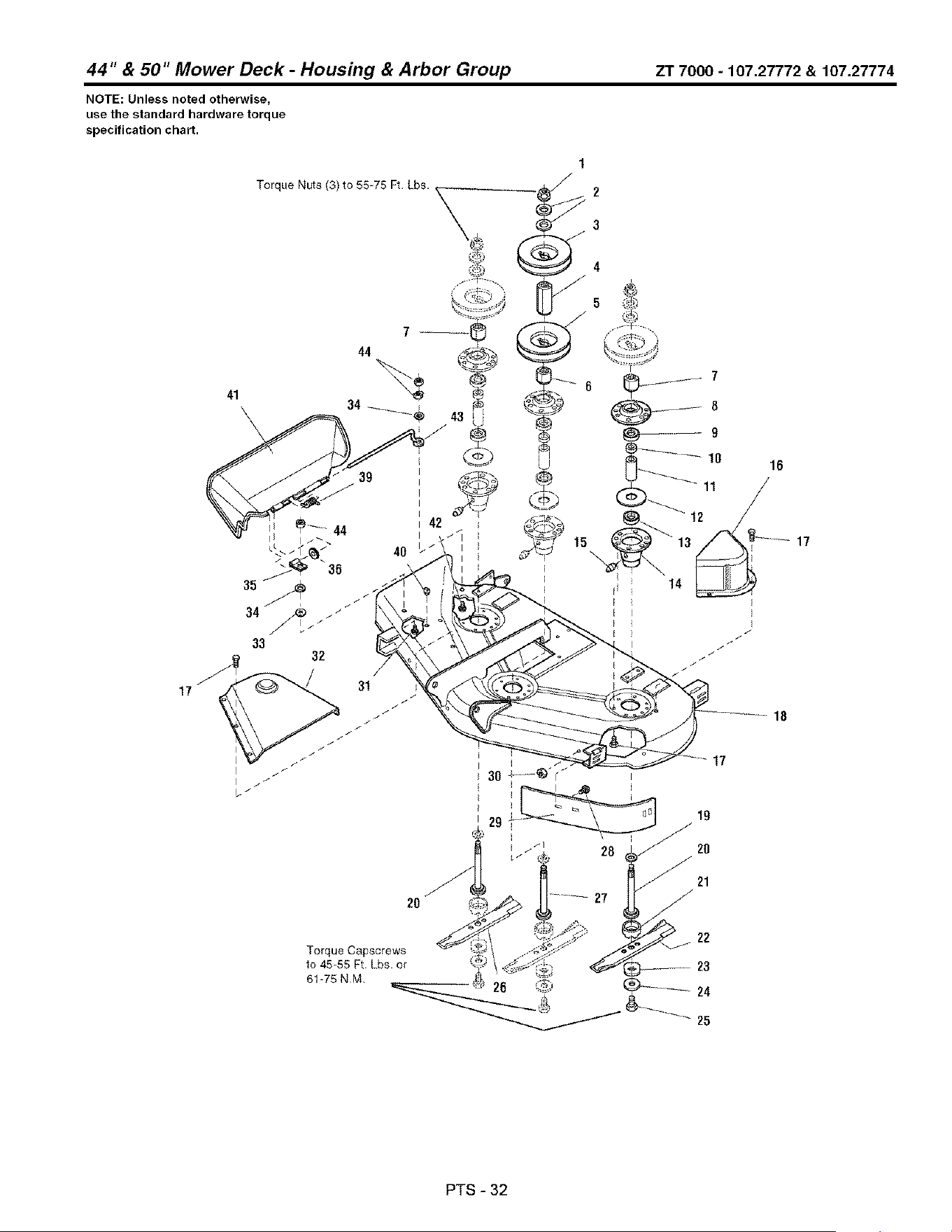
44" & 50" Mower Deck - Housing & Arbor Group ZT 7000 - 107.27772 & 107.27774
NOTE: Unless noted otherwise,
use the standard hardware torque
specification chart.
41
Torque Nuts (3) to 55-75 Ft. Lbs.
39
1
2
3
17
31
2O
18
Torque Oapscrews
to 45-55 Ft Lbs. or
61-75 NM
25
PTS-32

44" & 50" Mower Deck - Housing & Arbor Group
REF NO PART NO, QTY, DESCRIPTION
44 1920397SM 3 NUT, 1/4-20 ESNA
ZT7000-107.27772 & 107.27774
Footnotes
PTS-33
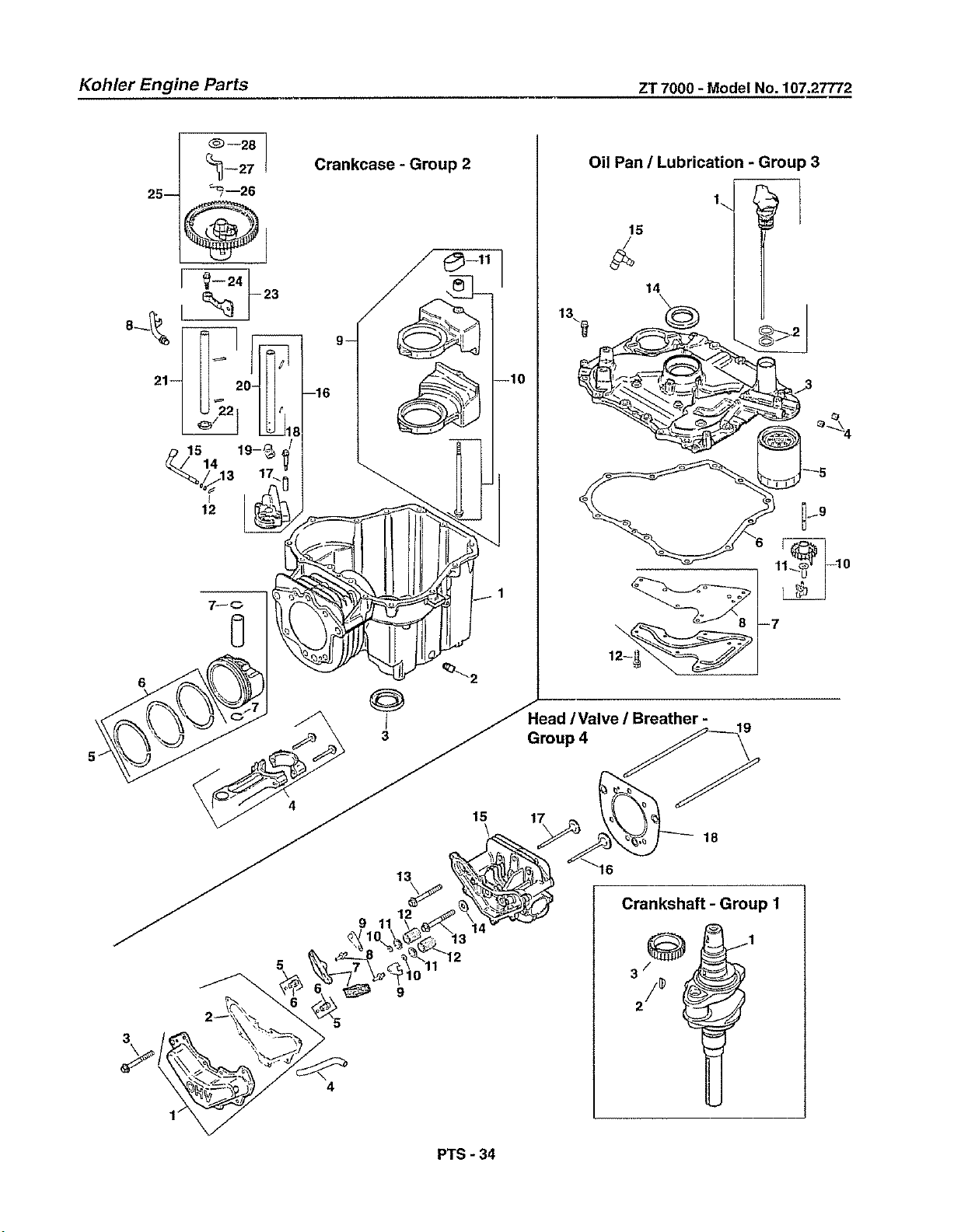
Kohler Engine Parts ZT 7000 - Model No. 107.27772
Crankcase - Group 2
15
14
13\9
Oil Pan / Lubrication - Group 3
4
PTS-34

Kohler Engine Parts ZT 7000 - Model No. 107.27774
RE}:. PART DESCRiPTiON REF. PART DESCRIPTION
SPECIAL PARTS
20 622 01 Short Block
20 766 05-3 Gasket Set
CRANKSHAFT - Group 1
1 20 014 14-S Crankshaft (includes 2)
2 X-42-15-S Key 3/18"
3 20 043 12-S Gear, crankshaft
CRANKCASE - Group 2
1
2
3 20 032 01-S
4 20 067 04-S
5 20 874 01-S
6 20 108 01-S
7 20 018 04-S
8 20 123 02-S
9 20 756 04-S
10 20 086 16-S
11 20 423 02-S
12 12 154 05-S
13 M-631015-S
14 X-26-102-S
16 20 144 02-S
16 20 393 02-S
17 20 112 02-S
18 20 086 13-S
19 20 032 07-S
20 20 144 04-S
21 20 144 06-S
22 20 468 01-S
23 20 090 01-S
24 20 086 06-S
25 20 010 03-S
26 20 089 06-S
27 20 044 18-S
28 20 468 03-S
Crankcase (USE: Short Block 20 522 01)
25 139 57-S Plug, sq. hd. pipe 3/8"
Seal, oil
Rod, connecting
Piston w/Ring Set (includes 7,8)
Ring Set (94 mm)
Retainer, piston pin (2)
Tube, drainback
Kit, balance weight (includes 10,11)
Kit, screw/guide pin
Shoe, guide
Clip, hitch pin
Washer, plain
Washer, plain
Shaft, governor cross
Pump assembly, oil (includes 16-19)
Spacer, oil pump screw (2)
Screw, oil pump (2)
Seal, oil pump outlet
Shaft center, cam - Intake
Shaft center, cam Exhaust (Includes 22)
Washer, thrust
Lever assembly, cam (2) (Includes 23)
Screw, shoulder
Gear assembly, cam (Includes 25-27)
Spring, ACR
Weight, ACR
Washer, thrust - ACR
OiL PAN/LUBRICATION - Group 3
1 20 040 02-S Kit, dipstick assembly (Includes 2)
20 163 01-S
20 009 03-S
4 25 139 80-S
5 52 050 02-S
6 20 041 01-S
7 20 096 02-S
8 20 041 02-S
9 20 144 03-S
10 20 310 03-S
11 12 380 01-S
12 M-546013-S
13 M-851030-S
14 20 032 01-S
15 25 166 02-S
O-Ring, dipstick (2)
Plate assembly, closure
(Includes 4,10,11 )
Plug, pipe (2)
Filter, oil
Gasket, closure plate
Kit, oil passage cover (includes 8)
Gasket, oil passage
Shaft, governor gear
Kit, gear & weight assembly (Includes11 )
Pin, governor regulating
Screw, hex. flange M5x0.8x13 (6)
Screw, hex. flange M8x1.25x30 (14)
Seal, oil
Connector, 90 °
HEAD/VALVE/BREATHER - Group 4
1 20 096 07-S Kit, valve cover (Includes 2)
2 20 041 13-S Gasket, valve cover
3 M-646020-S Screw, hex. flange M6xl.0x20 (7)
4 20 326 01-S Hose, breather
5 20 088 04-S Screw, set (2)
6 20 599 01-S Pivot, rocker arm (2)
7 20 186 01-S Arm, rocker (2)
6 20 086 03-S Stud, rocker (2)
9 20 146 03-S Plate, push rod guide (2)
10 20 062 01-S Lock, retainer (2)
11 20 173 01-S Cap, valve spring (2)
12 20 089 03-S Spring, valve (2)
13 20 086 02-S Screw, hex. flange M10x1.5x37 (6)
14 12 468 05-S Washer, flat 1/2"
15 20 318 01-S Head, cylinder
16 20 016 01-S Valve, exhaust
17 20 017 01-S Valve, intake
18 20 841 01-S Kit, cylinder head gasket (94 mm)
19 20 411 04-S Rod, push (2)
PTS - 35
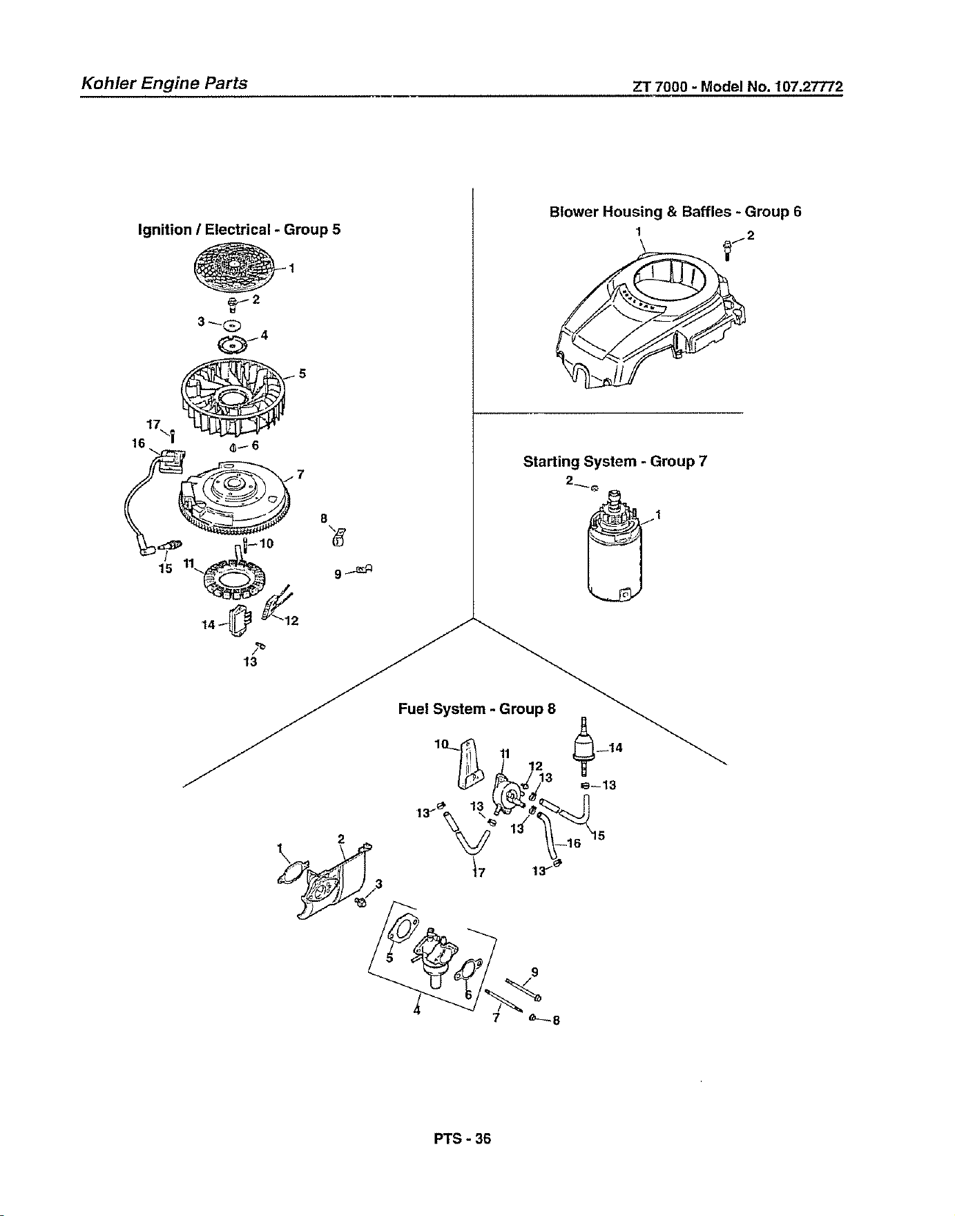
Kohler Engine Parts ZT 7000 - Model No. 107.27772
Ignition / Electrical - Group 5
_2
3_-Q
l_f @ s
16 e_6
Blower Housing & Baffles - Group 6
2
Starting System - Group 7
;J _Fuel System - Group 8_
PTS - 36
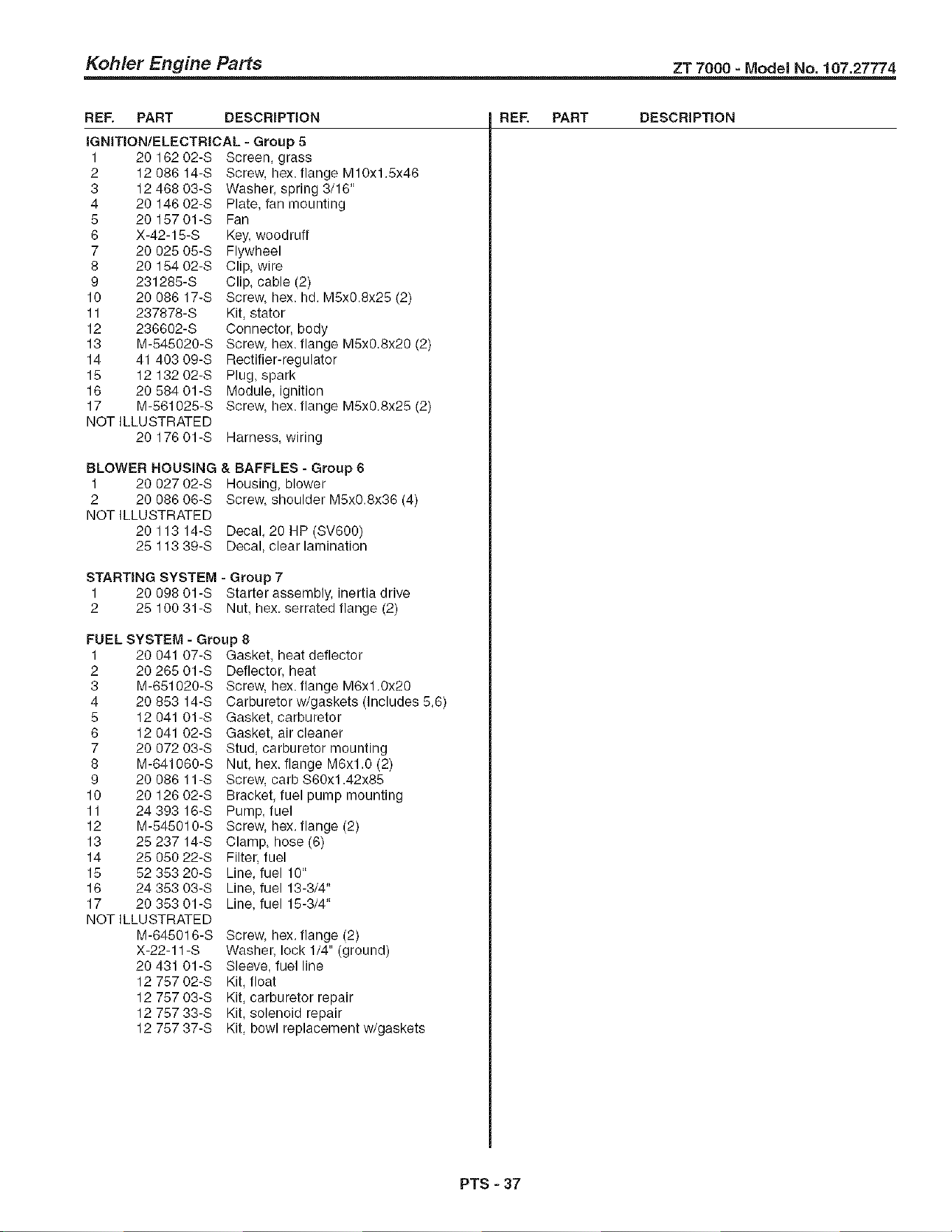
Kohler Engine Parts ZT 7000 - Model No. 107.27774
RE}:. PART DESCRiPTiON REF. PART DESCRiPTiON
IGNmON!ELECTRICAL - Group 5
1 20 162 02-S Screen, grass
2 12 086 14-S Screw, hex. flange M10x1.Sx46
3 12 468 03-S Washer, spring 3/16"
4 20 146 02-S Plate, fan mounting
5 20 15701-S Fan
6 X-42-15-S Key, woodruff
7 20 025 05-S Flywheel
8 20 154 02-S Clip, wire
9 231285-S Clip, cable (2)
10 20 086 17-S Screw, hex. hd. MSx0.Sx25 (2)
11 237878-S Kit, stator
12 236602-S Connector, body
13 M-545020-S Screw, hex. flange M5x0.8x20 (2)
14 41 403 09-S Rectifier-regulator
15 12 132 02-S Plug, spark
16 20 584 01-S Module, ignition
17 M-561025-S Screw, hex. flange MSx0.8x25 (2)
NOT ILLUSTRATED
20 176 01-S Harness, wiring
BLOWER HOUSING & BAFFLES - Group 6
1 20 027 02-S Housing, blower
2 20 086 06-S Screw, shoulder MSx0.8x36 (4)
NOT ILLUSTRATED
20 113 14-S Decal, 20 HP (SV600)
25 113 39-S Decal, clear lamination
STARTING SYSTEM - Group 7
1 20 098 01-S Starter assembly, inertia drive
2 25 100 31-S Nut, hex. serrated flange (2)
FUEL SYSTEM - Group 8
1 20 041 07-S Gasket, heat deflector
2 20 265 01-S
3 M-651020-S
4 20 853 14-S
5 12 041 01-S
6 12 041 02-S
7 20 072 03-S
8 M-641060-S
9 20 086 11-S
10 20 126 02-S
11 24 393 16-S
12 M-545010-S
13 25 237 14-S
14 25 050 22-S
15 52 353 20-S
16 24 353 03-S
17 20 353 01-S
NOT ILLUSTRATED
M-645016-S
X-22-11 -S
20 431 01-S
12 757 02-S
12 757 03-S
12 757 33-S
12 757 37-S
Deflector, heat
Screw, hex. flange M6x1.0x20
Carburetor w/gaskets (Includes 5,6)
Gasket, carburetor
Gasket, air cleaner
Stud, carburetor mounting
Nut, hex. flange M6xl.0 (2)
Screw, carb $60xl .42x85
Bracket, fuel pump mounting
Pump, fuel
Screw, hex. flange (2)
Clamp, hose (6)
Filter, fuel
Line, fuel 10"
Line, fuel 13-3/4"
Line, fuel 15-3/4"
Screw, hex. flange (2)
Washer, lock 1/4" (ground)
Sleeve, fuel line
Kit, float
Kit, carburetor repair
Kit, solenoid repair
Kit, bowl replacement w/gaskets
PTS - 37
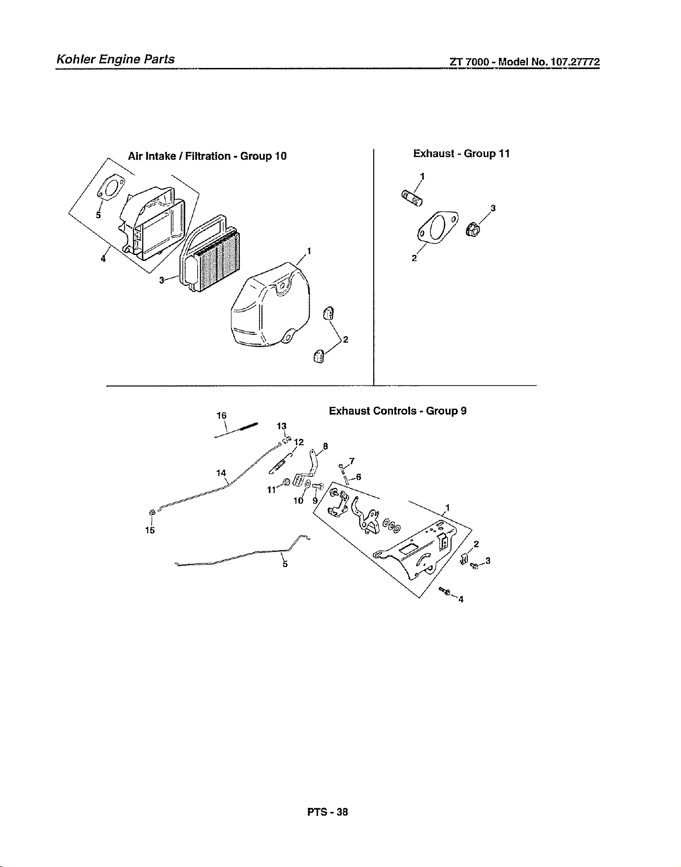
Kohler Engine Parts ZT 7000 - Model No. 107.27772
Air Intake / Filtration - Group 10
Exhaust-Group11
1
3
2
16
Exhaust Controls - Group 9
14
I
15
PTS-38
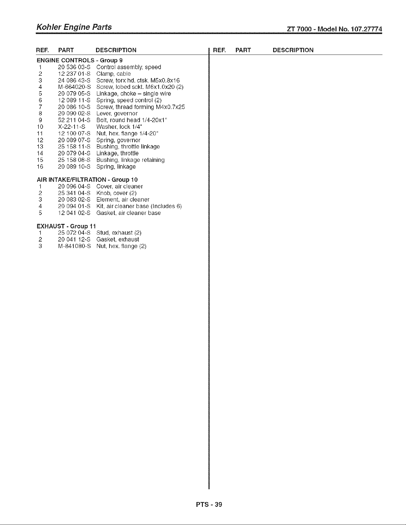
Kohler Engine Parts ZT 7000 - Model No. 107.27774
REF. PART DESCRiPTiON REF. PART DESCRiPTiON
ENGINE CONTROLS =Group 9
1 20 536 03-3 Control assembly, speed
2 12 237 01-S Clamp, cable
3 24 086 43-S Screw, torx hd. ctsk. M5x0.8x16
4 M-664020-S Screw, lobed sckt. M6xl.0x20 (2)
5 20 079 05-S Linkage, choke- single wire
6 12 089 11-S Spring, speed control (2)
7 20 086 10-S Screw, thread forming M4x0.7x25
8 20 090 02-S Lever, governor
9 52 211 04-S Bolt, round head 1/4-20x1"
10 X-22-11-S Washer, lock 1/4"
11 12 100 07-S Nut, hex. flange 1/4-20"
12 20 089 07-S Spring, governor
13 25 158 11-S Bushing, throttle linkage
14 20 079 04-S Linkage, throttle
15 25 158 08-S Bushing, linkage retaining
16 20 089 10-S Spring, linkage
AiR INTAKE/FILTRATION - Group 10
1 20 096 04-S Cover, air cleaner
2 25 341 04-3 Knob, cover (2)
3 20 083 02-3 Element, air cleaner
4 20 094 01-3 Kit, air cleaner base (Includes 6)
5 12 041 02-S Gasket, air cleaner base
EXHAUST - Group 11
1 25 072 04-S Stud, exhaust (2)
2 20 041 12-S Gasket, exhaust
3 M-841080-S Nut, hex. flange (2)
PTS - 39
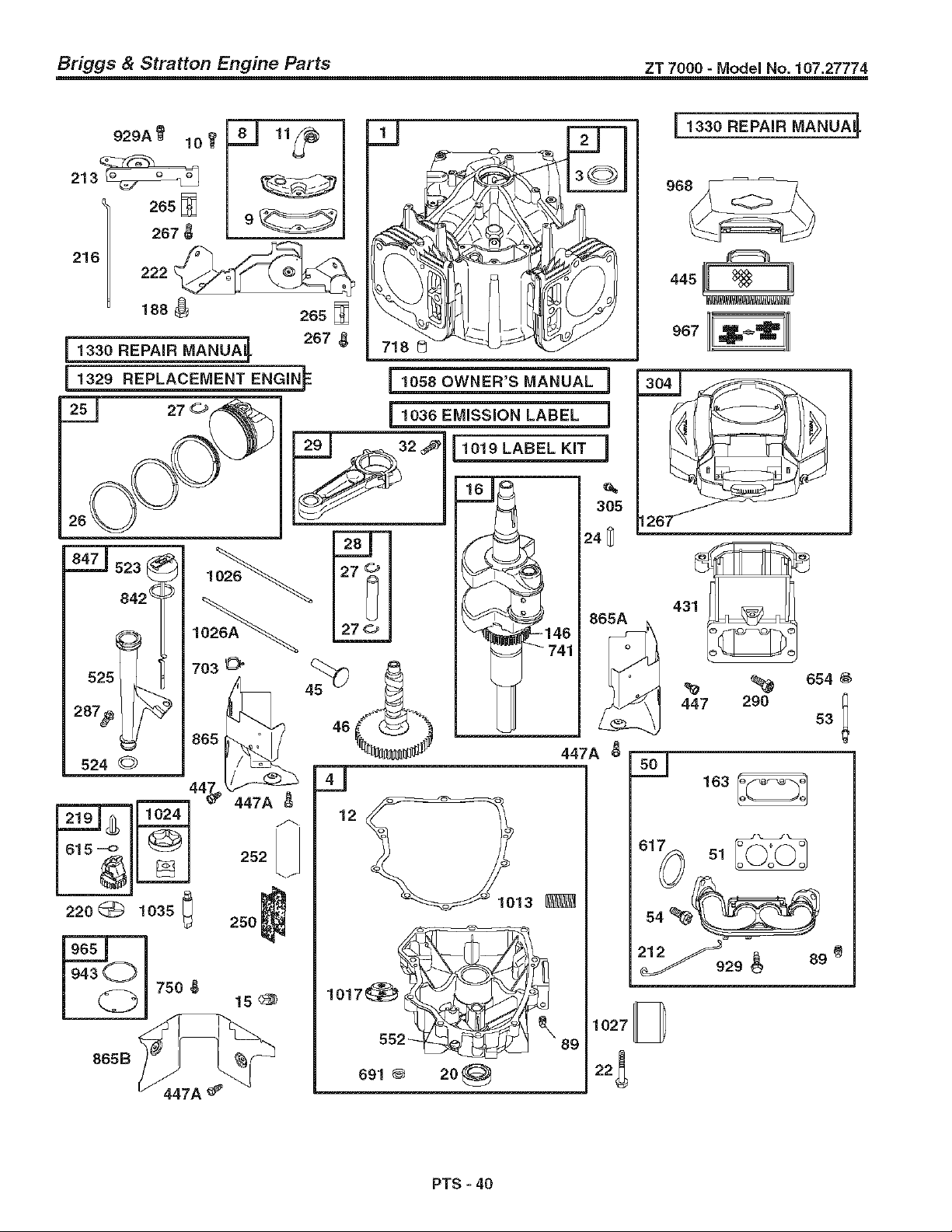
Briggs & Stratton Engine Parts zT 7000 - Model No. 107.27774
929A _'
10_
213_
265
267_
216 222
188 _ 265 [_
[1330 REPAIR IVlANUA_. 267 _,
B
1330 REPAIR IVlANUA_.
968
PTS - 40
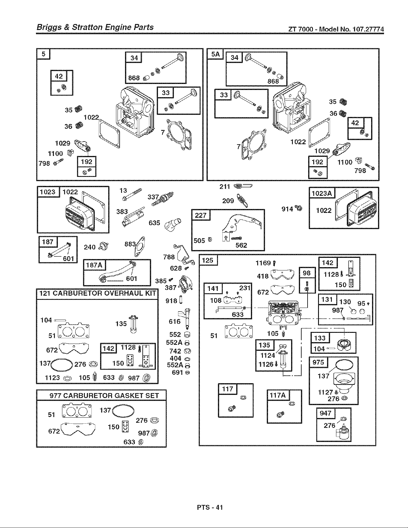
Briggs & Stratton Engine Parts ZT 7000 - Model No. 107.27774.
m
35
36
1029
1100
798
1022
1029
_11oo • _
798%
m
240_ 333_
211
_o_o_
628 _'
121 CARBURETOR OVERHAUL KiT
104_51_ 135_
137027°® o_
1123_ lO3_ 033® 937@
385 _ ,_
387':_
913 0
o16_
s52 Q
552A 8
742_
404©
552A 8
691
977 CARBURETOR GASKET SET
31_ 137C_
276
672_ 150_ 937@
633 @
914%
1169
413_ 9_.8
F??!],231o72_ _
l
51 _ lO5
142J_
1128_
150
_130 95_
104 '_
276 @
PTS -41
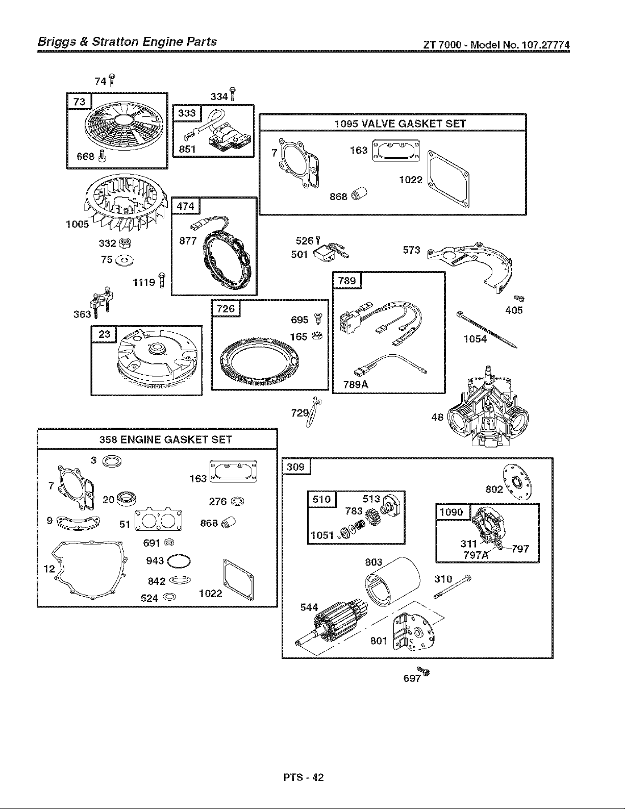
Briggs & Stratton Engine Parts ZT 7000 - Model No. 107.27774
741t
1095 VALVE GASKET SET
1022
868
358 ENGINE GASKET SET
3©
7_ 20_ 276®
729
=
789A
48
2_ 691 Q
1 943 Q
842
524
868
1022
801
PTS - 42

Briggs & Stratton Engine Parts ZT 7000 - Model No. 107.27774
REE PART
1 899742
2 499585
3 391086
4 699747
5 697580
5A 697581
7 690962
8 499601
9 690937
10 691108
11 690942
12 897227
13 791130
15 690946
16 699700
20 690947
22 694966
23 691053
24 222698
26 698429
26 698434
26 698430
26 898437
27 690975
28 690229
29 699699
32 699699
33 697576
34 499597
36 690963
36 690963
42 499586
48 690977
46 790562
48 698177
50 695241
51 690950
53 690951
54 699816
73 494439
74 698426
75 691086
89 690283
95 690718
98 699721
104 694918
106 698537
108 699723
117 699436
117A 699437
121 699734
126 791230
130 690993
131 499805
133 699724
136 699729
137 690994
141 899722
142 699726
146 690979
150 690995
163 691001
NOTES DESCRIPTION NOTES DESCRIPTION
*t
*t
Cylinder Assembly
Kit-Bushing/Seal (Magneto
Side)
Seal-Oil (Magneto Side)
Sump-Engine
Head-Cylinder (Cylinder 1)
Head-Cylinder (Cylinder 2)
Gasket-Cylinder Head
Breather Assembly
Gasket-Breather
Screw (Breather Assembly)
Tube-Breather
Gasket-Crankcase
Screw (Cylinder Head)
Plug-Oil Drain
Crankshaft
Seal-Oil (PTO Side)
Screw (Engine Sump)
Flywheel
Key-Flywheel
Piston Assembly (Standard)
Piston Assembly (.020"
Oversize)
Ring Set-Piston (Standard)
Ring Set-Piston (.020" Oversize)
Lock-Piston Pin
Pin-Piston
Rod-Connecting
Screw (Connecting Rod)
Valve-Exhaust
Valve-Intake
Spring-Valve (Intake)
Spring-Valve (Exhaust)
Keeper-Valve
Tappet-Valve
Camshaft
Short Block
Manifold-intake
Gasket-intake
Stud (Carburetor)
Screw (Intake Manifold)
Screen-Rotating
Screw (Rotating Screen)
Washer (Flywheel)
Plug-Oil
Screw (Throttle Valve)
Kit-Idle Speed
Pin-Float Hinge
Valve-Float Needle
Valve-Choke
Jet-Main (Standard)
Jet-Main (High Altitude)
Kit-Carburetor Overhaul
Carburetor
Valve-Throttle
Kit-Throttle Shaft
Float-Carburetor
Tube-Fuel Transfer
Gasket-Float Bowl
Kit-Choke Shaft
Nozzle-Carburetor
Key-Timing
Gasket-Nozzle
Gasket-Air Cleaner
REE PART
165 693148 Nut (Ring Gear)
167 698742 Line-Fuel (Cut to Required
Length)
187A 699883 Line-Fuel (Molded)
186 691108 Screw (Control Bracket)
192 690083 Adjuster-Rocker Arm
209 698071 Spring-Governor
211 691019 Spring-Governed Idle
212 695238 Link-Throttle
213 691021 Bracket-Choke Control
216 691022 Link-Choke
219 698231 Gear-Governor
220 690412 Washer (Governor Lever)
222 698761 Bracket-Control
227 691048 Lever-Governor Control
231 690718 Screw (Choke Valve)
240 695666 Filter-Fuel
250 690957 Retainer-Breather
252 890956 Collector-Oil
265 691024 Clamp-Casing
267 691044 Screw (Casing Clamp)
276 690997 ti: Washer-Sealing
287 691108 Screw (Dipstick Tube)
290 690341 Screw (intake Elbow)
304 698073 Housing-Blower
305 691005 Screw (Blower Housing)
309 691262 Motor-Starter
310 691263 Bolt (Starter Motor)
311 497608 Brush Set
332 691059 Nut (Flywheel)
333 691060 Armature-Magneto
334 691061 Screw (Magneto Armature)
337 491055 Plug-Spark
356 694012 Set-Engine Gasket
363 691062 Flywheel Puller
363 690966 Wrench-Spark Plug
385 691108 Screw (Fuel Pump)
387 808656 Pump-Fuel
404 690442 Washer (Governor Crank)
406 697820 Screw (Back Plate)
418 690999 Plate-Carburetor
431 790816 Elbow-intake
445 698754 Filter-Air Cleaner Cartridge
447 691003 Screw (Air Guide Cover)
447A 691108 Screw (Air Guide Cover)
474 696458 Alternator
501 691185 Regulator
505 691029 Nut (Governor Control Lever)
510 497606 Drive-Starter
513 692024 Clutch-Drive
523 691036 Dipstick
524 691032 Seal-Dipstick Tube
525 691037 Tube-Dipstick
526 691108 Screw (Regulator)
544 Armature-Starter (Service with
691262 Starter Motor)
552 890552 Bushing-Governor Crank
562A 690553 Bushing-Governor Crank
562 890311 Bolt (Governor Control Lever)
573 691009 Plate-Back
601 891038 Clamp-Hose
613 690341 Screw
615 698290 Retainer-Governor Shaft
616 691045 Crank-Governor
PTS - 43

Briggs & Stratton Engine Parts ZT 7000 - Model No. 107.27774
FIEF. PART DESCRIPTION REF. PART NOTES DESCRIPTION
617 697891
628 691108
633 690998
635 66536
654 690958
668 691215
672 690234
691 690657
698 693149
697 690372
703 691010
718 690959
726 499612
729 694123
741 690980
742 690328
780 696999
783 693058
788 691039
789 698330
789A 790544
797 691029
797A 693167
798 697890
801 691283
802 691286
8O3
842 691031
847 499602
851 493880
855 698072
865 691012
868A 691014
865B 691015
868 690968 *t
877 399916
883 690970
914 691127
918 694000
929 695239
929A 691003
943 690689
947 841546
968 499613
967 273638
968 698075
975 499810
977 499812
987 691000 _$
1008 698760
1013 690954
1017 690770
1019 690103
1022 690971 *t
1023 499599
1023A499600
1024 499054
1026 690981
1026A690982
1027 696864
1029 690972
1035 691042
1036 790626
NOTES
SeaI-O Ring (Intake Manifold)
Screw (Fuel Pump Bracket)
Seal-Choke/Throttle Shaft
Boot-Spark Plug
Nut (Carburetor)
Spacer
Gasket-Carburetor Plate
Seal-Governor Shaft
Screw (Ring Gear)
Screw (Drive Cap)
Clip
Pin-Locating
Gear-Ring
Clip-Wire
Gear-Timing
Retainer-E Ring
Screw (Oil Pump Cover)
Gear-Pinion
Bracket-Fuel Pump
Harness-Wiring
Harness-Wiring
Nut (Brush Retainer)
Nut (Brush Retainer)
Screw (Rocker Arm)
Cap-Drive
Cap-End
Housing-Starter (Service with
691262 Starter Motor)
Seal-Dipstick/Tube
Dipstick/Tube Assembly
Terminal-Spark Plug
Adapter-Air
Cover-Air Guide
Cover-Air Guide
Cover-Air Guide
Seal-Valve
Wire/Connector- Alternator
Gasket-Exhaust
Screw (Rocker Cover)
Hose-Vacuum
Screw (Choke Control Bracket)
Screw (Choke Control Bracket)
SeaI-O Ring (Oil Pump Cover)
Solenoid-Fuel
Cover-Oil Pump
Filter-Pre Cleaner
Cover-Air Cleaner
Bowl-Float
Gasket Set-Carburetor
Seal-Throttle Shaft
Fan-Flywheel
Nipple-Oil Filter
Screen-Oil Pump
Kit-Label
Gasket-Rocker Cover
Cover-Rocker (Cylinder 1)
Cover-Rocker (Cylinder 2)
Pump-Oil
Rod-Push (Steel)
Rod-Push (Aluminum)
Filter-Oil
Arm-Rocker
Shaft-Pump
Label-Emission
1051 691265
1054 280275
1058 275475
1090 691293
1095 694013
1100 690973
1119 691183
1124 690988
1126 690991
1127 695407
1128 690990
1169 690990
1267 698440
1329 40H777-0027
1330 273521
Ring-Retaining
Cable-Tie
Owner's Manual
Retainer-Brush
Gasket Set-Valve
Pivot-Rocker Arm
Screw (Alternator)
SeaI-O Ring (Fuel Transfer
Tube)
Screw (Fuel Transfer Tube)
Screw (Float Bowl)
Screw (Carburetor Nozzle)
Screw (Carburetor Cover Plate)
Latch-Blower Housing
Replacement Engine (If the orig-
inal engine is equipped with a 6
pin transfer to the original
engine)
Repair Manual
* included in Engine Gasket Set, Key. No. 358
Included in Carburetor Overhaul Kit, Key, No. 121
:l: Included in Carburetor Gasket Set, Key. No. 977
1 Included in Valve Gasket Set, Key. No. 1095
PTS - 44
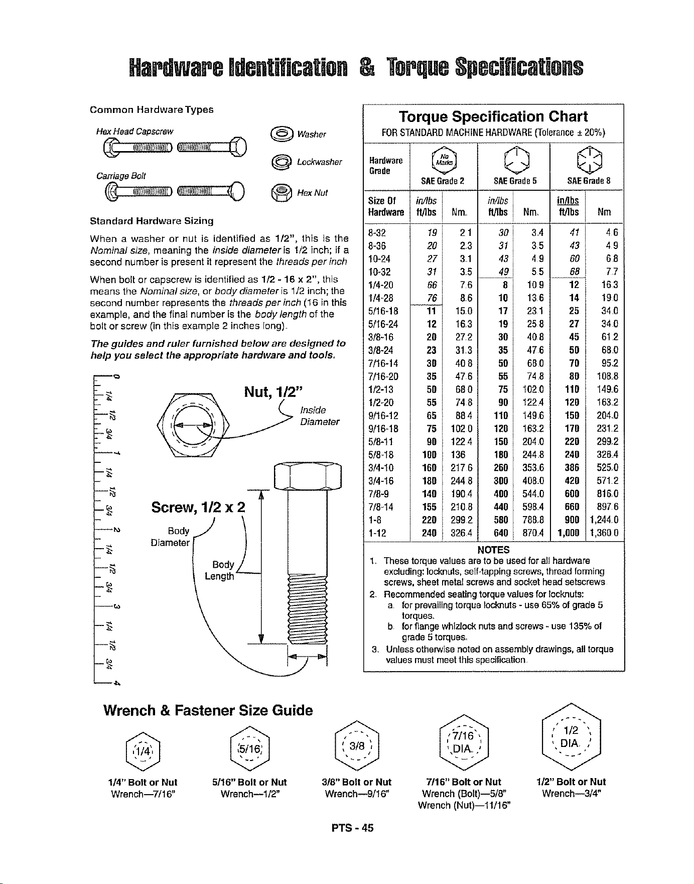
HardwaregdefitificatiaH
Terqu8SpBcificatigfis
Common Hardware Types
HexHead Capscrew
CarriageBolt
(_Washer
(_ Lockwasher
O HexNut
Standard Hardware Sizing
When a washer or nut is identified as 1/2", this is the
Nominal size, meaning the inside diameter is 1/2 inch; if a
second number is present it represent the threads per inch
When bolt or capscrew is identified as 1/2 - 16 x 2", this
means the Nominalsize, or bodydiameteris 1/2 inch; the
second number represents the threads per inch (16 in this
example, and the final number is the body length of the
bolt or screw (in this example 2 inches long)
The guides and ruler furnished below are designed to
help you select the appropriate hardware and tools.
m_
L
Nut, 1/2"
Inside
Diameter
Screw, 1/2 x 2 -3
OadyJ |
Diameterl Body'_ -
Torque Specification Chart
FORSTANDARDMACHINEHARDWARE(Tolerance_*20%)
Hardware @
Grade
SAEGrade2
Size Of in//bs
Hardware ft]]bs Nm
8-32
8-36
10-24
10-32
1/4-20
1/4-28
5/16-18
5/16-24
3/8-16
3/8-24
7/16-14
7/16-20
1/2-13
1/2_20
9/16-12
9/16-18
5/8-11
5/8-18
3/4-10
3/4-16
7/8-9
7/8-14
1-8
1-12
19 21
20 2_3
27 31
31 35
66 76
76 86
11 150
12 163
20 272
23 313
30 40 8
35 476
50 68 0
55 74 8
65 88 4
75 102 0
90 122 4
100 136
160 217 6
180 2448
140 1904
155 210.8
220 2992
240 3264
© ©
SAEGrade5 8AEGrade8
in/Ibs in_b_
flJ]bs Nm. Wlbs Nm
113'441
31 35 43
4 9 60
_4_ 5 5 68
8 109 12
10 136 14
17 231 25
19 25 8 27
30 40 8 45
35 47 6 50
50 68 0 70
55 74 8 80
75 102 0 110
90 1224 120
110 1496 150
120 163.2 170
150 2040 220
180 2448 240
260 3536 386
300 408_0 420
400 5440 600
440 5984 660
580 788_8 900
640 8704 1,0OO
NOTES
46
49
68
77
163
190
34 0
34 0
61 2
68 0
95,2
1088
1496
1632
2040
2312
299,2
3264
525,0
5712
8160
897 6
1,244 8
1,3600
1 These torque valcasare to be used for all hardware
excluding: Iocknuts, self-tapping screws, threadforming
screws, sheet metal screws and socket head setscrews
2. Recommended seating torque values for locknuts:
a for prevailing torque locknuts- use 65% of grade 5
torques,
b for flange whizlock nuts and screws * use 135% of
grade 5 torques_
3. Unless otherwise noted on assembly drawings, all torque
values must meet this specification
Wrench & Fastener Size Guide
1/4" Bolt or Nut 5/16" Bolt or Nut 3!8" Bolt or Nut 7/16" Bolt or Nut
Wrench--7/16" Wrench--I/2" Wrench--9/16" Wrench (Bolt)--5/8"
Wrench (Nut)--11/16"
1/2" Bolt or Nut
Wrench--3/4"
PTS - 45

PTS- 46

Repair Protection Agreements
Congratulations on making a smart purchase. Your new
Craftsman® product is designed and manufactured for
years of dependable operation. But like all products, it
may require repair from time to time.That's when having
a Repair Protection Agreement can save you money and
aggravation.
Purchase a Repair Protection Agreement now and pro-
tect yourself from unexpected hassle and expense.
Here's what's included in the Agreement:
Expert service by our 12,000 professional repair
specialists
Unlimited service and no charge for parts and
labor on all covered repairs
Product replacement if your covered product can't
be fixed
Discount of 10% from regular price of service and
service-related parts not covered by the agreement;
also, 10% off regular price of preventive maintenance
check
Fast help by phone - phone support from a Sears
technician on products requiring in-home repair, plus
convenient repair scheduling.
Once you purchase the Agreement, a simple phone call
is all that it takes for you to schedule service.You can call
anytime day or night, or schedule a service appointment
online.
Sears has over 12,000 professional repair specialists,
who have access to over 4.5 million quality parts and
accessories. That's the kind of professionalism you can
count on to help prolong the life of your new purchase for
years to come. Purchase your Repair Protection
Agreement today!
Some limitations and exclusions apply. For prices
and additional information call 1-800-827-6655.
Sears Installation Service
For Sears professional installation of home appliances,
garage door openers, water heaters, and other major
home items, in the U.S.A. call f-800-4-MY-HOME®
Acuerdo de Protecci6n de Reparaciones
Feticidades por su compra inteligente. Su nuevo produc-
to de Craftsman® fue disefiado y fabricado para aSos de
operaci6n confiable. Pero como todos los productos, es
posible que cada cierto tiempo requiera de reparaciones.
Ahf es donde tener un Acuerdo de Protecci6n de
Reparaciones puede ahorrarle dinero y contrariedades.
Compre un Acuerdo de Proteceidn de Reparaeiones
ahora y protejase usted mismo de motestias y gastos
inesperados.
Aqui est,. Io que incluye el Acuerdo:
5_ Servicio experto de nuestros 12,000 especialistas
profesionales en reparaci6n
Servicio ilimitado y sin cargo per las partes y la
mano de obra en todas las reparaciones cubiertas
Reemplazo del producto si su producto cubierto no
puede ser arreglado
Descuento del 10% del precio regular de servicio y
E_ partes relacionadas con el servicio no cubierto per el
acuerdo; adem_.s, de un 10% de descuento del pre-
cio regular por revisiones de mantenimiento preventive
Ayuda r&pida por tel_fono - soporte telef6nico de
t_cnicos de Sears sobre productos que requieren
reparaciones a domicilio, adem_.s de programaci6n
conveniente de reparaci6n.
Una vez que compre el Acuerdo, una simple Ilamada
telef6nica es Io unico que se necesita para que le pro-
gramen el servicio. Usted puede Ilamar a cualquier hora
del dfa o de la noche, o programar una cita de servicio
pot Intemet.
Sears cuenta con ma.s de 12,000 especialistas profe-
sionales en reparaci6n, que tienen acceso a m_.s de 4.5
millones partes y accesorios de calidad. Ese es el tipo
de profesionalismo con el que usted puede contar para
ayudarle a prolongar la vida de su nueva compra per
muchos afios venideros, iCompre su Acuerdo de
Protecci6n de Reparaciones hoy!
Aplican algunas limitantes y exclusiones. Para
obtener informaci6n sobre el precio e informaci6n
adicional llame al 1-800-827-6655,
Servicio de Instalaci6n de Sears
Para obtener informaci6n sobre la instalaci6n profesional
de Sears para electrodom_sticos, abridores para
cocheras, calentadores de agua y otros art[culos
grandes, en los Estados Unidos Ilame a f-800-4-MY-HOME®

Your Home
For repair-in your home-of all major brand appliances,
lawn and garden equipment, or heating and cooling systems,
no matter who made it, no matter who sold it! ...............
For the replacement parts, accessories and
owner's manuals that you need to do-it-yourself.
For Sears professional installation of home appliances
and items like garage door openers and water heaters.
1-800-4-MY-HOME ® (1-800-469-4663)
Call anytime, day or night (U.S.A. and Canada)
iiii!iiiiiiiiiiiiiiii
www,sears.com www.sears.ca
Our Home
For repair of carry-in items like vacuums, lawn equipment,
and electronics, call or go on-line for the location of your nearest
Sears Parts & Repair Center.
1-800-488-1222
Call anytime, day er night (U.S.A. only)
www.sears.com
To purchase a protection agreement (U.S.A.)
or maintenance agreement (Canada) on a product serviced by Sears:
...........................1-800-827-6655 (U.S.A.) 1-800-361-6665 (Canada)
iii:i_iiiii_iiiii!i:ii_!,iiii!jiiii_
iii:i_iiiii_iiiii!i:ii_!,iiii!jiiii_
Para pedir servicie de reparaci6n
a domicilio, y para ordenar piezas:
1=888-SU-HOGAR sM
(1-888-784-6427)
Au Canada pour service en frangais:
1-800-LE-FOYER M°
(1-800%33-6937)
www.sears.ca
TM Sbl
(_ Registered Trademark / Trademark / Service Mark of Sears, Roebuck and Co.
SM
CeMarca Registrada / TMMarca de FAbrica / " Mama de Servicio de Sears, Roebuck and Co.
MD
MCMarque de commerce / Marque dgposee de Sears, Roebuck and Co. 6) Sears, Roebuck and Co.