Loading ...
Loading ...
Loading ...
5,)Correct Depth Gauges
a.); Place depth gauge tool over each cutter
• depth gauge. Figure 32,
b.) File level with the flat tile if depth gauge is
higher than the depth gauge tool,
c,) Maintain rounded front corner of depth
gauge with a fiat file. Figure 32&33.
NOT_: The very top of the depth gauge
shoutd be flat withthe front half-rounded -
' • off with a flat tile.
I & WARNING
Depth ga_e tool is required to insure proper depth
gauge. Fifi_he depth gauge too deep wilt increase
the chance Of kickback which-can result in serious
iniury.
b. CHAIN RIEPLACEMENT
1.) Use only the Low-Kick Chain specified for
_your saw in "Specifications" for replace.
.Z,::_:.ment chain.
_)_i;Reptace the chain when cutters or links
.... br_,ako
3.) See your Sears Service Center to replace
and sharpen individual cutters for match-
. ing your chain.
4.) Atwayshave a worn sprocket replaced by
...... y0urSearsServiceCenterwheninstalling
a new chain to.avoid excessivewear to the
chain.
REMOVE SAWDUST
FROM GUIDE BAR GROOVE
2. GUIDE BAR MAINTENANCE
• Conditions which can require guide bar
maintenance:
_saw cuts to one side
--saw has to be forced through a cut
--inadequate supply of oil to bar and
chain,
• Check the condition of the guide bar each
time the chain is sharpened. A worn guide
bar will damage the chain and make cut-
ting more difficult.
• Replace the guide bar when:
--the inside groove of the guide bar rails is
WON'I.
--the guide bar is bent 0rcracked.
• Use only the ReducedJ<ickback Guide Bar
specified for your saw in "Specifications" for
replacement.
a. Remove the guide bar to Service.
b. Clean oil-holes at least once for each five
hours Of operation:Figure 34,
c. Remove Sawdust from the guide bar
groove periodically witt_ a putty knife or
a wire, Figure 34,
d. Remove buKs by filing the side edges
of the guide bar grooves square with a
'flat fi-le:Figure 35.
e. Restore eqUateedges to an uneven rai!
top by filing with a tlal file. F_jure 35.
CORRECT
GUIDE BAR WORN-GROOVES FILE EDGES
GROOVE SQUARE
OIfL HOLES
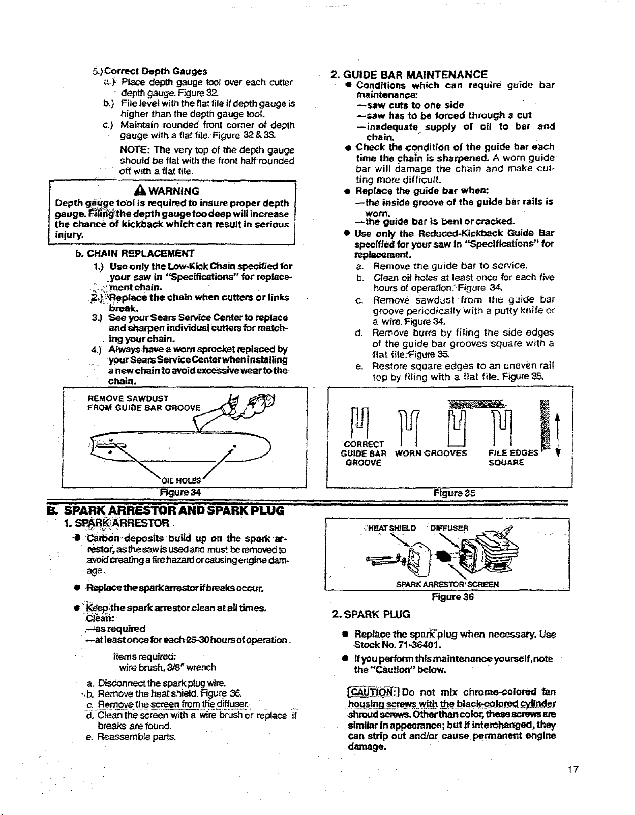
13. SPARK ARRESTOR AND SPARK PLUG
: -dep s ts bu.duponthe sparkar-
. ' restor, aslhesawisusedand must be removed to
avoid creating afire hazard orcausing engine dam-
age.
• Rep_v_ethesparkarrestorifbre.aks occur.
• __l?;the spark arrestor.clean at alt times.
.C]_:-
Rgure 35
sp K ............
Figure 36
2. SPARK PLUG
_--_asrequired
--at least once foreach,25-30 hours of operation.
items required:
wire brush, 3/8 _wrench
a. Disconnect the spark plug wire.
-,b. Removethe heatshield. Figure 36.
.c: ..Een_ore i:__. o'eenS__m._e .d.iff.u_.F: _
d, Clean the screen with a ._re brush or replace it
breaks are found.
e. Reassemb_ parts.
• Replace the spark-plug when necessary. Use
Stock No, 71_6401.
I Ifyou perform thts maintenance yourself, note
the "Caution" below.
|CAUTION:IDo not mix chrome-colored fan
ho__sln_g.._...W.._ ._tf:_...b..!.a.c__l_=_qy_l_der.
.shroud screws.Otherthan color,thesescrewsare
similar In appearance; but If interchanged, they
can strip out andJor cause, permanent engine
damage.
17
Loading ...
Loading ...
Loading ...