Use and Care & Installation Guide
Zoneline
®
Air Conditioner
GE Appliances
Model: Zoneline
®
Heat/Cool Model
2100-10 Series
Safety Instructions ........................ 2
Operating Instructions, Tips
Air Louvers................................................3, 10
Control Settings ..............................................3
Fan Cycle Switch ........................................... 5
Freeze Sentinel ........................................... 5
Other Features ....................................... 4, 5
Room Cabinet ............................................. 3
Ventilation Control..................................... 4
Care and Cleaning
Air Filter............................................................ 5
Base Pan .......................................................... 6
Control Panel .................................................. 6
Outdoor Coil.................................................... 6
Room Cabinet and Case .............................. 6
Problem Solver.............................. 12
More questions ?…call
GE Answer Center
®
800.626.2000
Installation
Electrical Requirements............................... 7
Extension Cords ............................................. 7
Grounding........................................................ 7
Installation Instructions ......................... 7-11
Consumer Services.................. 15
Appliance Registration................................. 2
Important Phone Numbers....................... 15
Model and Serial Number Location.......... 2
Warranty ....................................... Back Cover
WARNING—When using this appliance,
always exercise basic safety precautions,
including the following:
• Use this air conditioner only for its intended
purpose as described in this Use and Care Guide.
• This air conditioner must be properly installed
in accordance with the Installation Instructions
before it is used.
• Never use an extension cord with this air
conditioner.
• Unplug or disconnect the unit at the fuse box
or circuit breaker before making any repairs.
NOTE: We strongly recommend that any servicing
be performed by a qualified individual.
• For your safety…Do not store or use combustible
materials, gasoline or other flammable vapors or
liquids in the vicinity of this or any other appliance.
IMPORTANT SAFETY INSTRUCTIONS
Read all instructions before using this appliance.
2
HELP US HELP YOU
Before using your air conditioner,
read this guide carefully.
It is intended to help you operate and maintain your
new air conditioner properly.
Keep it handy for answers to your questions.
If you don’t understand something or need more
help, call:
GE Answer Center
®
800.626.2000
24 hours a day, 7 days a week.
If you received a damaged air
conditioner…
Immediately contact the dealer (or builder) that sold
you the air conditioner.
Save time and money.
Before you request service…
Check the Problem Solver section of this guide.
It lists causes of minor operating problems that you
can correct yourself.
Write down the model and serial numbers.
You’ll see them on a label behind the room cabinet.
These numbers are also on the Consumer Product
Ownership Registration Card that came with your air
conditioner. Before sending in this card, please write
these numbers here:
Model Number
Serial Number
Use these numbers in any correspondence
or service
calls concerning your air conditioner.
IF YOU NEED SERVICE
To obtain service, see the Consumer Services page in
the back of this guide.
We’re proud of our service and want you to be
pleased. If for some reason you are not happy with
the service you receive, here are steps to follow for
further help.
FIRST, contact the people who serviced your
appliance. Explain why you are not pleased. In most
cases this will solve the problem.
NEXT, if you are still not pleased, write all the
details—including your phone number—to:
Manager, Consumer Relations
GE Appliances
Appliance Park
Louisville, KY 40225
SAVE THESE INSTRUCTIONS
3
OPERATING THE CONTROLS
Important Safety Instructions Operating the Controls Room Cabinet
Thermostat Control Operation Switch
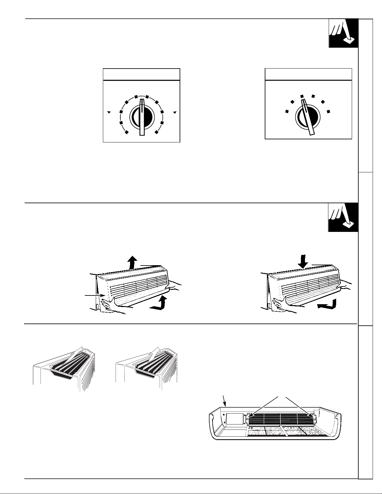
The thermostat knob is
used to control the room
temperature. The unit
automatically cycles on
and off to maintain room
temperature.
A comfortable
temperature will be
maintained in most
rooms when the control
is set at about “5” or “6”.
HI HEAT provides
heating with high fan
speed operation.
LO HEAT provides
heating with low fan
speed operation.
STOP setting stops
heating or cooling.
However, power
remains connected
to the unit and the Freeze Sentinel still functions.
FAN provides fan operation without cooling or heating.
HI COOL provides cooling with high fan speed
operation.
LO COOL provices cooling with low fan speed
operation.
4
8
3
THERMOSTAT
56
7
9
10
1
2
8
3
L
E
R
O
O
C
M
E
R
R
A
W
OPERATION
FAN
HI HEAT
LO COOL
LO COOL
LO HEAT
STOP
TO REMOVE THE ROOM CABINET
Additional controls are located behind the room cabinet.
To remove:
Pull out to release it
from the tabs. Then
lift up.
To replace:
Place the tabs over
the top rail. Push
inward until it snaps
into place.
Room Cabinet
Air Louvers
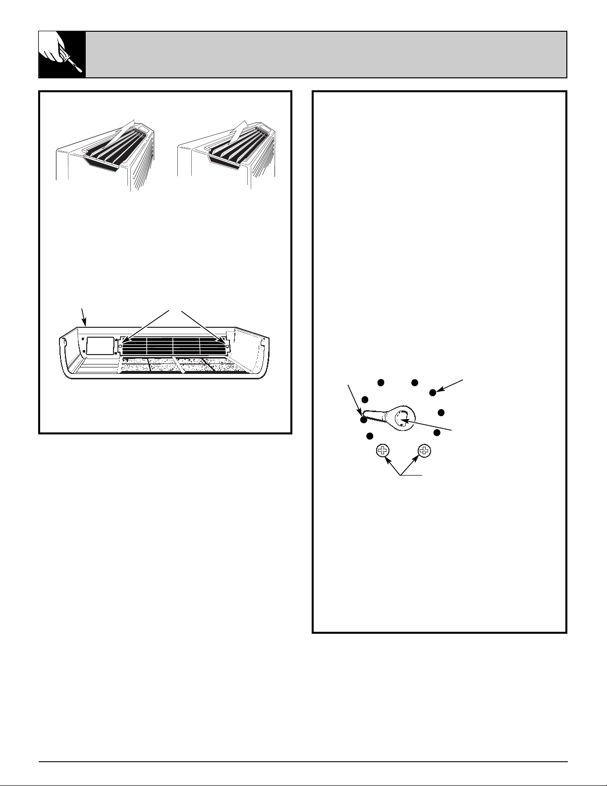
To change the louver direction, remove the room
cabinet and 2 louver screws that hold the louvers in
place. Turn the louver section 180˚ (end for end),
replace the screws and replace the room cabinet. The
textured face of the louver section must be toward the
room side.
NOTE: For high-mounted Zonelines where greater
room cabinet louver adjustments are required, order
the RAF45 Room Cabinet.
The direction of the heated or cooled air may be adjusted by
removing and turning the louvers around.
Louver Screws
Room Cabinet
4
OTHER FEATURES
Ventilation Control
The ventilation control lever is located at the lower
left side of the unit, behind the room cabinet.
This knob is set at CLOSE at the factory. When in
this position, the vent door is closed and only indoor
air is circulated by the air conditioner.
Switching the knob to OPEN opens the vent door
to allow outdoor air to enter the room. However,
leaving the vent door OPEN reduces heating or
cooling effectiveness and increases operating costs.
Remote Control Central Desk Control (CDC)
The unit may be controlled either by the controls
on the unit or connecting to a low voltage remote
thermostat.
See Installation Instructions.
The unit may be connected to a Central Desk Control
system by connecting the wires from the central control
system to the CDC leads located in a compartment
behind the room cabinet. These leads may also be used
as an interface for other systems used to control the unit
such as motion detectors, key-activated systems, etc.
The Freeze Sentinel remains in an active mode to help
protect against low temperature damage even though
the unit may be OFF at the central control location.
See Installation Instructions.
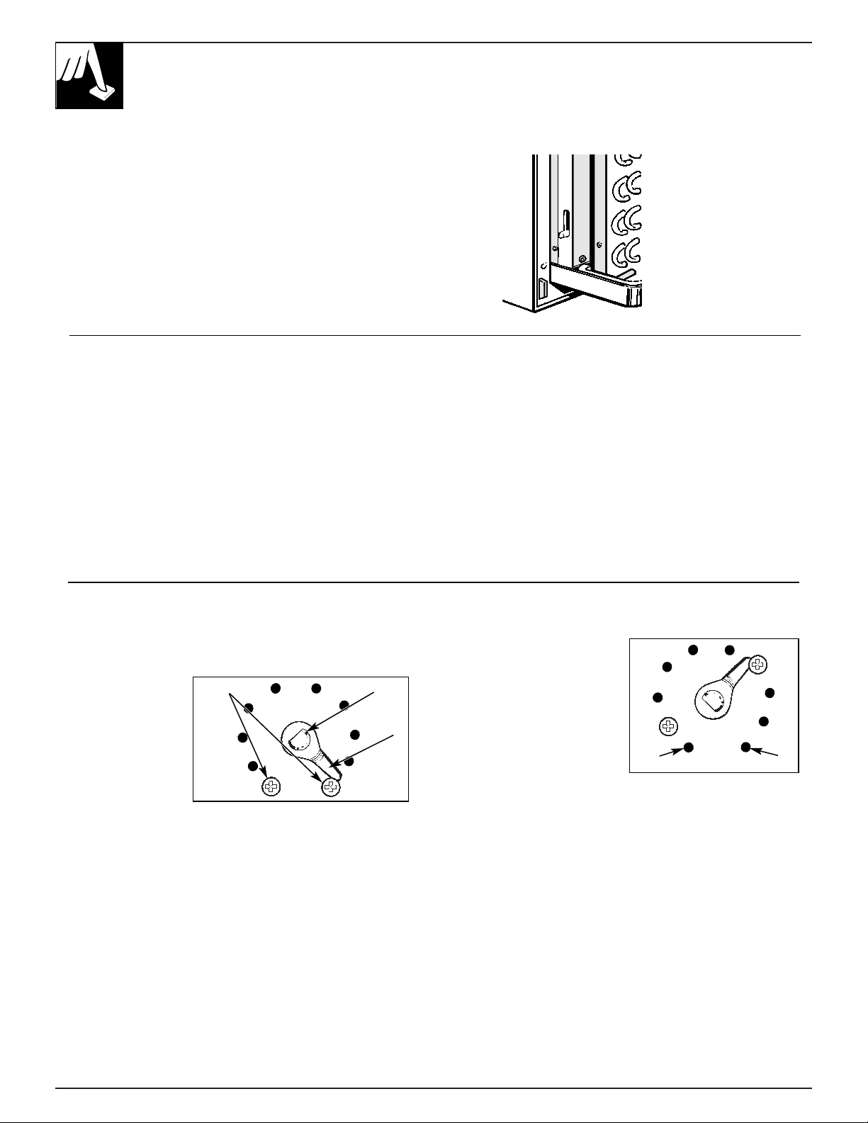
Temperature Limiter
The normal range of the thermostat control is
approximately 60°F. to 85°F.
The control range
may be narrowed
by the use of the
temperature
limiting screws
located behind
the control panel.
To set the limiting screws:
1. Remove the room cabinet.
2. Pull both THERMOSTAT knob and the
OPERATION knob off the shafts and remove the
control panel.
3. Remove and relocate either or both stop screws on
the exposed control box cover.
To limit the maximum
heating temperature,
move the stop screw at
the left of the knob shaft
clockwise. To limit the
minimum cooling
temperature, move the
stop screw on the right
counterclockwise.
Make sure the stop arm is
between the stop screws as shown.
Because actual room temperature can be affected by
location and installation as well as outdoor weather
conditions, you may want to experiment to determine
the stop screw locations that best meet your
temperature requirements.
After adjusting the limiting screws, reinstall the
control panel, knobs and room cabinet.
OPEN
CLOSE
Stop Screws
Stop
Arm
Knob Shaft
(Warmest)
(Coldest)
OPEN
CLOSE
Fan Cycle Switch Freeze Sentinel
The Fan Cycle Switch is located under the control
panel behind the room cabinet. This switch is set at
CONT at the factory to provide continuous fan
operation in cool or heat modes. Leaving the switch
in the CONT setting allows continuous circulation
of room air and will result in a more balanced
temperature throughout the room. If you want the fan
to cycle on and off with the compressor or resistance
heater, set the switch at CYCLE.
The Freeze Sentinel sensor helps prevent plumbing
damage due to sub freezing temperatures—even if you
have turned the operation switch to STOP. The sensor
automatically turns on the heater and fan if the room
temperature falls to about 40°F.
You do not have to do anything to activate the Freeze
Sentinel. It will work as long as power to the unit has
not been interrupted.
Other Features Care and Cleaning
5
CARE AND CLEANING
Turn the Zoneline off before cleaning.
Air Filters
The Zoneline air filters should be cleaned at least
every 30 days. Clogged filters reduce cooling,
heating and air flow.
Keeping these filters clean will:
• Decrease cost of operation.
• Save energy.
• Prevent clogged heat exchanger coils.
• Reduce costly compressor problems.
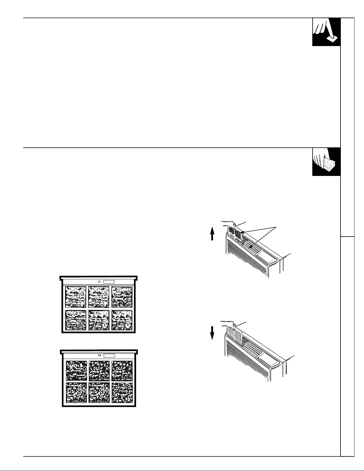
To remove the air filters:
To clean the air filters:
• Vacuum off the heavy soil.
• Run water through the filters.
• Dry thoroughly before replacing them.
To replace the air filters:
NOTE: Do not operate the Zoneline without the
filters in place. If a filter becomes torn or damaged
it should be replaced immediately. Operating the unit
without the filters in place or with damaged filters will
allow dirt and dust to reach the indoor coil and reduce
the efficiency of the unit.
Replacement filters are available from your GE dealer,
GE Service and Parts Center or authorized Customer
Care
®
servicers.
FRONT
30 days – needs cleaning
FRONT
60 days – cooling, heating and airflow are greatly reduced.
F
R
O
N
T
Pull up
2 Air Filters
Front
Push
down

CARE AND CLEANING
(continued)
Room Cabinet & Case Control Panel
Wash the room cabinet and case finish with mild soap
or detergent and lukewarm water.
The control panel is shipped with a protective plastic
film. This film can be left on or removed. To clean,
use a damp cloth and mild detergent.
Outdoor Coil Base Pan
The coil on the outdoor side of the unit should be
checked periodically and cleaned if clogged with dirt
or soot from the atmosphere. If extremely dirty, it may
need to be professionally steam cleaned, a service
available through many GE service outlets.
In some installations dirt or other foreign matter may
be blown into the unit from the outside and settle in
the base pan (the bottom of the unit).
Check the base pan periodically and clean it out,
if necessary.
6
7
INSTALLATION INSTRUCTIONS
BEFORE YOU BEGIN
Read these instructions completely and
carefully.
IMPORTANT—Observe all governing codes and
ordinances.
INSTALLER—Be sure to leave these
instructions with the Consumer.
CONSUMER—Keep these instructions for
future reference.
CAUTION
Before starting the installation, the power to
the direct connect wiring should be OFF.
THE GE ZONELINE
®
* Shipped with the chassis
**Check essential elements list on chassis
ELECTRICAL REQUIREMENTS
FOR PERSONAL SAFETY:
• Follow National Electrical Code (NEC) and
local codes, ordinances and regulations. All
wiring—including installation of receptacle,
must be in accordance with these codes.
• This unit must be properly grounded.
• Do not use an extension cord with this unit.
• NEC requires permanent connection for
installations over 250 volts.
• Protective devices (fuses or circuit breakers)
acceptable for Zoneline installations are
specified on the nameplate of each unit.
• Aluminum building wiring may pose special
problems—consult a qualified electrician.
• Disconnect power to the air conditioner before
servicing by:
1. Removing the power cord from the wall
receptacle, if it has one.
2. Removing the branch circuit fuses or turning
the circuit breakers off at the panel.
TOOLS NEEDED
Phillips screwdriver
Flat Blade screwdriver
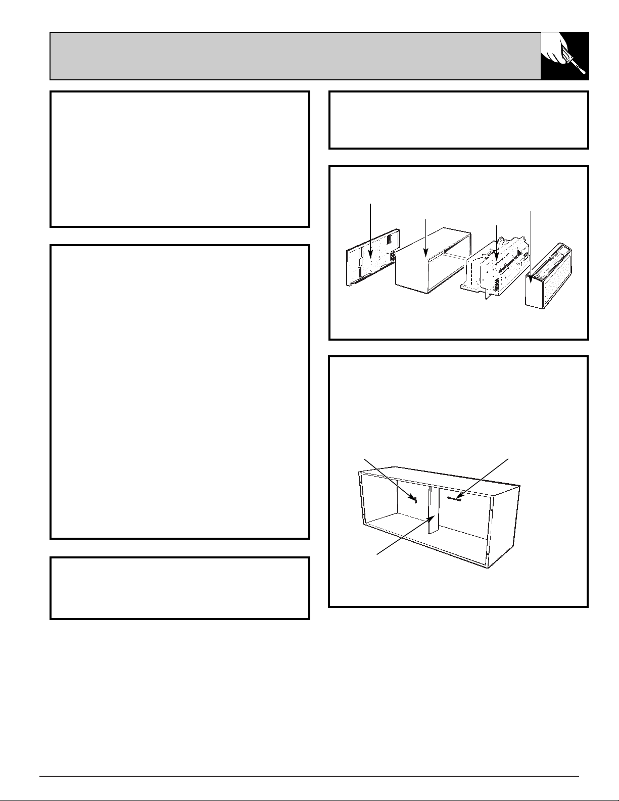
Exterior Grille/Louver**
Wall Case**
Chassis
Room Cabinet*
WALL CASE & GRILLE
1. The RAB 70 or 77 Wall Case must be properly
installed per instructions packed with the case.
2. Remove the corrugated stiffener and the
outdoor protective panel. Use the slit in the
outdoor panel as a handhold and push out.
3. Install the Exterior Grille from the room side
per instruction packed with the grille.
Protective Panel
Slit
Stiffener
8
INSTALLATION INSTRUCTIONS
(continued)
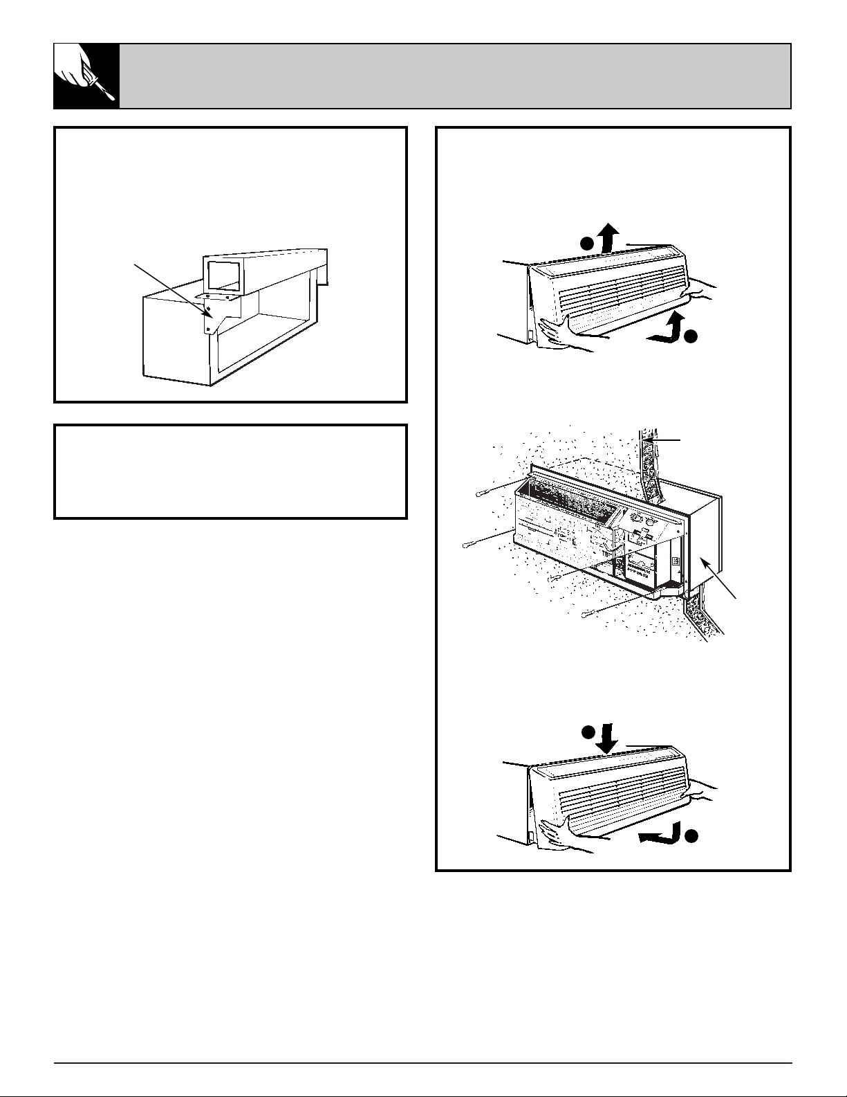
INSTALLATION
1. Remove the room cabinet by pulling out at the
bottom to release it, then lift it up to clear the
rail along the chassis top.
2. Slide the chassis into the wall case and
secure with four screws through the
chassis flange holes.
3. Reinstall the room cabinet by hooking the
top over the rail along the chassis top, then
pushing it in at the bottom.
NEW DUCTED INSTALLATION
If this unit is to be installed in a new ducted
application using a duct adaptor kit, the kit must
be installed before the chassis is placed in the
wall case. The Installation Instructions are packed
with the kit.
Mounting Plate
Duct
Case
EXISTING DUCTED INSTALLATION
Replacement of an existing ducted unit may
require different components. Request this
information from your sales representative.
Wall
Wall Case
1
2
1
2
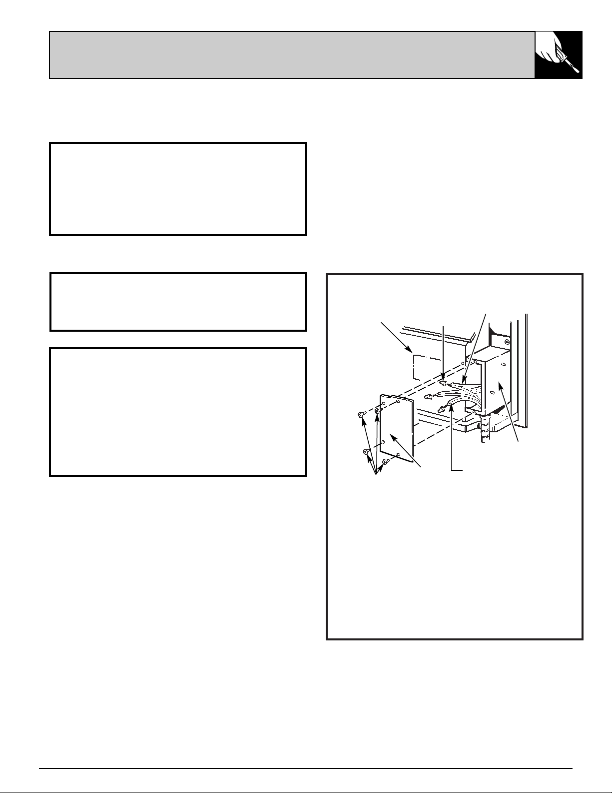
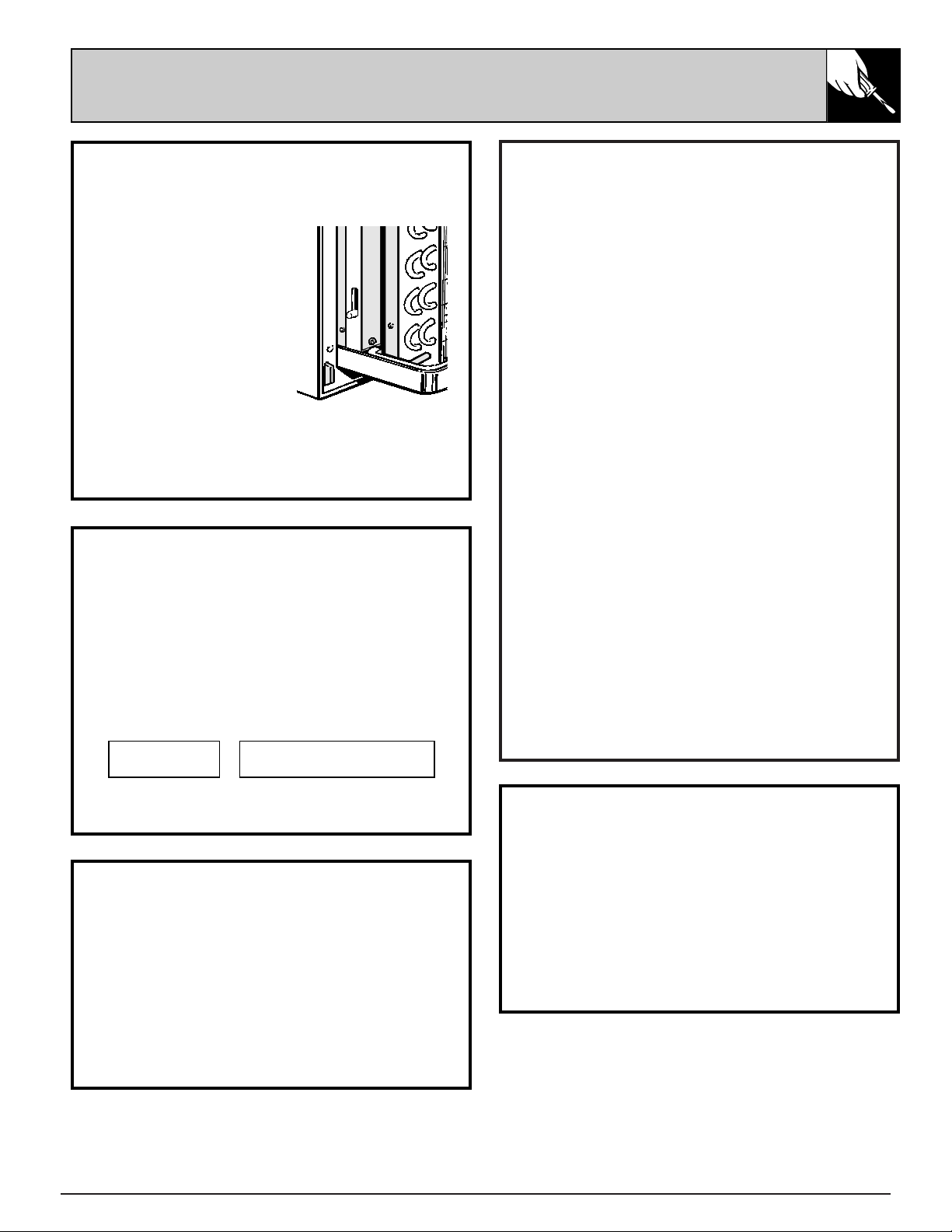
INSTALLATION
1. Remove the Room Cabinet from chassis by
lifting up and out to clear mounting brackets.
2. Remove four “a” screws and the cover plate
from the mounting plate.
3. Attach the field supplied conduit to the
mounting plate.
4. Connect Power Supply Conductors to the
Inner Conductors with wire nuts.
5. Dress the wiring inside the compartment
and attach the cover plate.
6. Reinstall the Room Cabinet.
9
208/230 volt model is equipped for connection
with a power cord according to unit capacity at
the time of shipment.
Should local code or special requirements specify
permanent connection of this unit, use adapter kit
RAK-400.
PREPARATION
1. The electrical rating marked on the previously
installed Zoneline must be the same as the
supply branch circuit.
2. The unit provides for connection of 1/2”
trade size electrical conduit and provision for
connection to a wiring system in accordance
with the National Electric Code ANSI/NFPA
No. 70-1993.
Electrical
Junction Box
Wire Nut
Cover Plate
FOR 208/230 VOLT UNITS
All 265V units are direct connected and come
with the cover plate and mounting plate (junction
box). The conduit is field-supplied by the installer.
FOR 265 VOLT UNITS
Inner Conductors
Power Supply
Conductors
Mounting
Plate
a
PERMANENT CONNECTION
10
INSTALLATION INSTRUCTIONS
(continued)
TEMPERATURE LIMITING
The normal range of the thermostat control is
approximately 60°F. to 85°F. The control range
may be narrowed by the use of the temperature
limiting screws located behind the control panel.
Repositioning the screw on the left will limit the
maximum temperature about 3°F. for each hole
in a clockwise rotation; the screw on the right will
limit the minimum temperature when moved
counterclockwise. Limiting the maximum and
minimum settings prevents users from turning the
controls to extreme positions. Restrictions to full
rotation of the thermostat knob may require
explanation to the room occupant that unit will
provide comfortable conditions at settings allowed.
To access the limiting screws, remove the room
cabinet, remove the Thermostat knob and the
Operation knob by pulling each knob off its shaft
and removing the control panel. Set the limiters to
the desired setting, replace the control panel and
the control knobs. If the original settings do not
allow sufficient room temperature control the
limiter screws may have to be repositioned.
If the temperature limiters are used it is
recommended that the limiters be set no higher
than the second hole from the original bottom
position. This provides an operating range
between approximately 66°F. and 79°F. In order
to maximize the benefit of the temperature
limiting it may be necessary to adjust the limiter
screws seasonally to allow unoccupied rooms to
be maintained at moderate temperatures (i.e.,
heating season temperatures limited between
60°F. and 75°F.; cooling season temperatures
limited between 85°F. and 65°F.).
AIR LOUVERS
To change the louver direction, remove the room
cabinet and 2 louver screws that hold the louvers
in place. Turn the louver section 180° (end for
end), replace the screws and replace the room
cabinet. The textured face of the louver section
must be toward the room side.
NOTE: For high-mounted Zonelines where greater
room cabinet louver adjustments are required,
order the RAF45 Room Cabinet.
The direction of the heated or cooled air may be adjusted by
removing and turning the louvers around.
Louver Screws
Room Cabinet
Stop Link
Tapped Holes (10)
(Warmest)
(Coldest)
Thermostat
shaft
Stop location as shipped
CLASS 2 REMOTE CDC
11
CENTRAL DESK CONTROL
The unit may be connected to a switch at the
front desk. When the switch is OPEN the unit is
operable. When the switch is CLOSED, the unit is
made inoperative. Connect the wires from the
central control system to the “CDC” interface
leads in the compartment above the rating
plate. Detailed hook-up instructions are in the
compartment. Follow the recommended wire
sizing in the table below. Two wires must be
used from each CDC switch to each individual
unit. Good wiring practices (e.g. twisted pairs,
SEPARATION FROM POWER CIRCUITS) must be
followed to minimize induced voltages which
may harm the control system. Do not use a
common buss in the CDC wiring. A 24 volt
transformer is contained within the unit and no
external voltage should be applied to the unit
through the CDC leads. These leads may also be
used as an interface for other systems used to
control the unit, such as motion detectors, key-
activated systems, etc. The Freeze Sentinel
remains in an active mode to help protect against
low temperature damage even though the unit
may be “OFF” at the central control location.
Recommended Wire Size for Central Desk
Control Installation
Wire Size # AWG Maximum Allowable Length
#22 600 ft.
#20 900 ft.
#18 1500 ft.
#16 2000 ft.
VENTILATION CONTROL
The VENTILATION control lever is located at the
lower left side of the unit, behind the room cabinet.
This lever controls the
vent door and is set in the
CLOSE position at the
factory so outdoor air will
not enter the room
through the unit and only
indoor air is circulated by
the air conditioner.
Moving the lever to OPEN
opens the vent door and
draws outdoor air through
the air conditioner and into the room. Leaving
the vent door OPEN during extreme temperature
conditions reduces heating or cooling
effectiveness and increases operating costs.
OPEN
CLOSE
REMOTE CONTROL – 2100-10 SERIES
The unit may be controlled either by the unit-
mounted controls or by installing three and six
wire connectors located in the compartment
above the rating plate. Detailed instructions are
included in the compartment.
1 STAGE HEAT–
1 STAGE COOL
MANUAL THERMOSTAT
LOW VOLTAGE
TERMINALS ON ZONELINE
•••
••••••
FREEZE SENTINEL
The unit is equipped with a sensor that
automatically turns on the resistance heater and
fan if the room temperature, as sensed at the unit,
drops to approximately 40°F. and will shut the
heater off when the temperature reaches about
52°F. The Freeze Sentinel system helps prevent
damage due to sub-freezing temperatures and
will operate regardless of the mode setting of the
unit. Freeze Sentinel is active as long as power to
the unit has not been interrupted.
FAN CYCLE SWITCH
The fan cycle switch is located under the control
panel behind the room cabinet. This switch is set
at CONT at the factory to provide continuous fan
operation in cool or heat modes. Leaving the
switch in the CONT setting allows continuous
circulation of room air and will result in a more
uniform temperature throughout the room.
Setting the switch at CYCLE will cause the fan
to cycle on and off with the compressor or
resistance heater.
12
QUESTIONS?
USE THIS PROBLEM SOLVER
PROBLEM POSSIBLE CAUSE
AIR CONDITIONER • Power cord not plugged in, fuse blown, or circuit breaker tripped.
DOES NOT OPERATE
• Unit is waiting for compressor overload protector to reset.
AIR CONDITIONER • Curtains, blinds or furniture blocking the front of the air conditioner will
“DOES NOT COOL OR restrict air flow.
HEAT AS IT SHOULD”
• Thermostat Control may not be set high enough. Turn the control to a lower or
higher number. (NOTE: In some installations, the Thermostat Control cannot
be turned all the way to “1” or “10”. This is normal. Do not attempt to force
the control beyond its stopping points.)
• Dirty air filter blocking air flow. Filter should be cleaned at least every
30 days. See instructions in cleaning section.
• Room may have been very hot or very cold when the air conditioner was first
turned on. Allow time for it to cool down or warm up.
• Ventilation control may be set at OPEN position, allowing outside air to
enter the room.
“BURNING” ODOR AT • Dust on the surface of the heating element can cause a “burning” odor at the
START OF HEATING beginning of the heating operation. This odor should quickly fade.
OPERATION
OPERATING SOUNDS • Relay clicks may be heard when the compressor or fan cycles on and off.
This is normal.
• Fan runs continuously when the unit is operating unless the Fan Cycle Switch
under the control panel is set at CYCLE. Then the fan cycles on and off
with the heater.
AIR IS NOT ALWAYS • The fan switch may be set at Fan Cont (continuous). This causes the fan
COOL DURING to blow room temperature air even when the compressor cycles off.
COOLING OPERATION The continuous air movement provides better overall temperature control.
AIR IS NOT ALWAYS • The fan switch may be set at Fan Cont (continuous). This causes the fan
HOT DURING to blow room temperature air even when the heat source cycles off.
HEATING OPERATION The continuous air movement provides better overall temperature control.
If you need more help...call, toll free:
GE Answer Center
®
800.626.2000
consumer information service

13
The Problem Solver
NOTES

14
NOTES
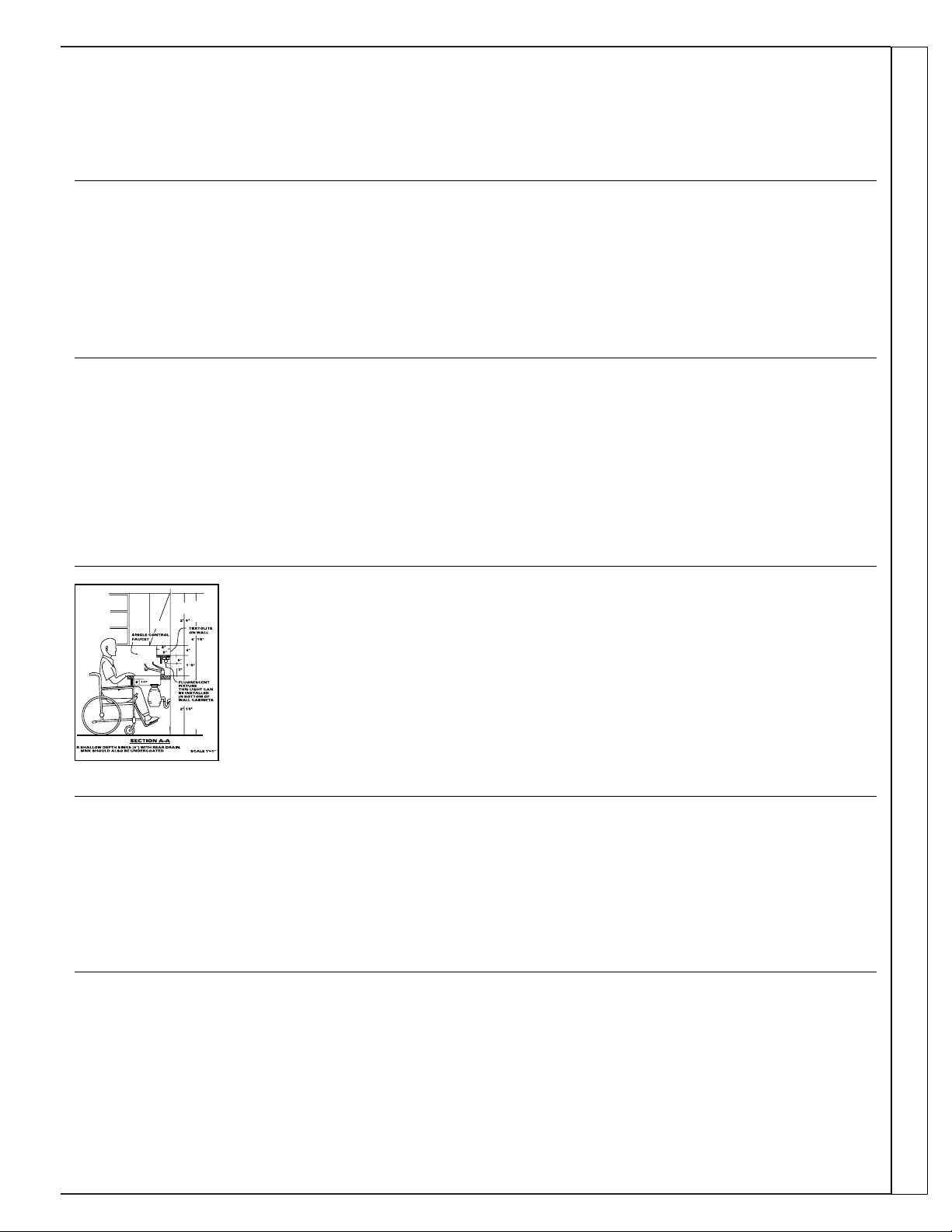
Upon request, GE will provide
Braille controls for a variety of
GE appliances, and a brochure
to assist in planning a barrier-free
kitchen for persons with limited
mobility. To obtain these items,
free of charge, call 800.626.2000.
Consumers with impaired hearing or speech who have
access to a TDD or a conventional teletypewriter may
call 800-TDD-GEAC (800-833-4322) to request
information or service.
We’ll Be There
With the purchase of your new GE appliance, receive the assurance that if you ever need
information or assistance from GE, we’ll be there. All you have to do is call—toll-free!
In-Home Repair Service
800-GE-CARES (800-432-2737)
A GE consumer service professional will provide expert repair service,
scheduled at a time that’s convenient for you. Many GE Consumer Service
company-operated locations offer you service today or tomorrow, or at your
convenience (7:00 a.m. to 7:00 p.m. weekdays, 9:00 a.m. to 2:00 p.m. Saturdays).
Our factory-trained technicians know your appliance inside and out—so most
repairs can be handled in just one visit.
GE Answer Center
®
800.626.2000
Whatever your question about any GE major appliance, GE Answer Center®
information service is available to help. Your call—and your question— will be
answered promptly and courteously. And you can call any time. GE Answer
Center® service is open 24 hours a day, 7 days a week.
Service Contracts
800-626-2224
You can have the secure feeling that GE Consumer Service will still be there
after your warranty expires. Purchase a GE contract while your warranty is still in
effect and you’ll receive a substantial discount. With a multiple-year contract,
you’re assured of future service at today’s prices.
Parts and Accessories
800-626-2002
Individuals qualified to service their own appliances
can have needed parts or accessories sent directly to
their home. The GE parts system provides access to over
47,000 parts…and all GE Genuine Renewal Parts are
fully warranted. VISA, MasterCard and Discover cards
are accepted.
User maintenance instructions contained in this booklet
cover procedures intended to be performed by any user.
Other servicing generally should be referred to qualified
service personnel. Caution must be exercised, since
improper servicing may cause unsafe operation.
For Customers With Special Needs…
800.626.2000
Consumer Services
15

8-97 CG (JR)
Pub. No. 49-7365
Zoneline
What Is Not
Covered
FULL ONE-YEAR WARRANTY
For one year from date of original
purchase, we will provide, free of
charge, parts and service labor on site to
repair or replace any part of the Zoneline
that fails because of a manufacturing
defect.
FULL FIVE-YEAR WARRANTY
For five years from the date of original
purchase, we will provide, free of
charge, parts and on-site service labor
to repair or replace any part of the sealed
refrigerating system (the compressor,
condenser, evaporator and all
connecting tubing) that fails because
of a manufacturing defect.
LIMITED 2ND THROUGH
5TH YEAR PARTS WARRANTY
For the second through the fifth year
from date of original purchase, General
Electric will provide, free of charge,
parts that fail as a result of a
manufacturing defect. Parts covered are
fan motors, switches, thermostat,
heater, heater protectors, compressor
overload, solenoids, circuit boards,
auxiliary controls, thermistors, Freeze
Sentinel, frost controls, ICR pump,
capacitors, varistors, and indoor blower
bearing. This is a limited parts-only
warranty, and does not include labor or
transportation to and from the service
shop.
This warranty is extended to the original purchaser and any succeeding owner for products purchased for use
within the USA and Canada. In Alaska, the warranty excludes the cost of shipping or service calls to your site.
Some states do not allow the exclusion or limitation of incidental or consequential damages. This warranty gives you
specific legal rights, and you may also have other rights which vary from state to state. To know what your legal rights
are in your state, consult your local or state consumer affairs office or your state’s Attorney General.
Staple sales slip or cancelled check here. Proof of original purchase
date is needed to obtain service under warranty.
For service in the U.S., call 800-GE-CARES.
For service in Canada, call 1-800-361-3400.
ZONELINE
WARRANTY
What Is Covered
• Service trips to your site to teach you
how to use the product.
• Improper installation.
If you have an installation problem,
or if the air conditioner is of
improper cooling capacity for the
intended use, contact your dealer
or installer. You are responsible for
providing adequate electrical
connecting facilities.
• Replacement of fuses or resetting of
circuit breakers.
• In commercial locations, labor
necessary to move the unit to a
location where it is accessible for
service by an individual technician.
• Failure of the product resulting from
modifications to the product or due
to unreasonable use including failure
to provide reasonable and necessary
maintenance.
• Failure due to corrosion on models
not corrosion-protected.
• Damage to product caused by
improper power supply voltage,
accident, fire, floods or acts of God.
• Incidental or consequential damage
to personal property caused by
possible defects with this air
conditioner.
Warrantor: General Electric Company. Louisville, KY 40225

