Loading ...
Loading ...
Loading ...
6 | SHC 2.5 www.stiebel-eltron-usa.com
OPERATION | INSTALLATION
Plumbing Connections
8. Plumbing Connections
!
IMPORTANT:
IF WATER PIPES ARE OF COPPER OR BRONZE,
USE DIELECTRIC CONNECTIONS TO PREVENT
HEATER CORROSION. FAILURE TO PROVIDE DI-
ELECTRIC INSULATION MAY RESULT IN PREMA-
TURE TANK OR NIPPLE FAILURE AND MAY VOID
YOUR WARRANTY.
!
NOTICE:
HARD WATER OR WATER WITH A HIGH MINER-
AL COUNT MAY DAMAGE THE UNIT. DAMAGE TO
THE UNIT CAUSED BY SCALE OR A HIGH MINER-
AL COUNT IS NOT COVERED UNDER THE WAR-
RANTY.
CAUTION:
TO REDUCE THE RISK OF EXCESSIVE PRESSURE
AND TEMPERATURE IN THE WATER HEATER, A
COMBINATION TEMPERATURE/PRESSURE (P & T)
RELIEF VALVE HAS BEEN PROVIDED AND MUST
BE INSTALLED.
CAUTION:
NEVER PLUG THE WATER HEATER‘S CORD INTO
AN ELECTRICAL OUTLET UNLESS IT IS FILLED
WITH WATER. OTHERWISE, THE UNIT WILL GET
DAMAGED BEYOND REPAIR.
!
NOTICE:
WHEN A WATER HEATER IS INSTALLED IN A
CLOSED WATER-SUPPLY SYSTEM, SUCH AS ONE
HAVING A BACK-FLOW PREVENTER IN THE COLD-
WATER SUPPLY, MEANS SHALL BE PROVIDED TO
CONTROL THERMAL EXPANSION. CONTACT THE
WATER SUPPLIER OR LOCAL PLUMBING INSPEC-
TOR FOR INFORMATION REGARDING THE CON-
TROL OF THIS SITUATION.
Connect the cold water pipe to the cold water connection
on the unit (blue). Connect the hot water pipe to the hot
water connection on the unit (red).
Ensure that the water heater is installed in a level po-
sition.
Install a shut off on the cold-water side of the water
heater. This is for emergency shut-off. It must be kept
open when the water heater is operating.
When using copper piping, solder a piece of tubing to
a threaded fi tting (union) before screwing the adapter
to the tank.
BRAIDED FLEX HOSE CONNECTORS ARE ALSO RECOM-
MENDED.
DO NOT APPLY HEAT DIRECTLY TO INLET OR OUTLET
CONNECTIONS.
D0000034988
2
1
4
3
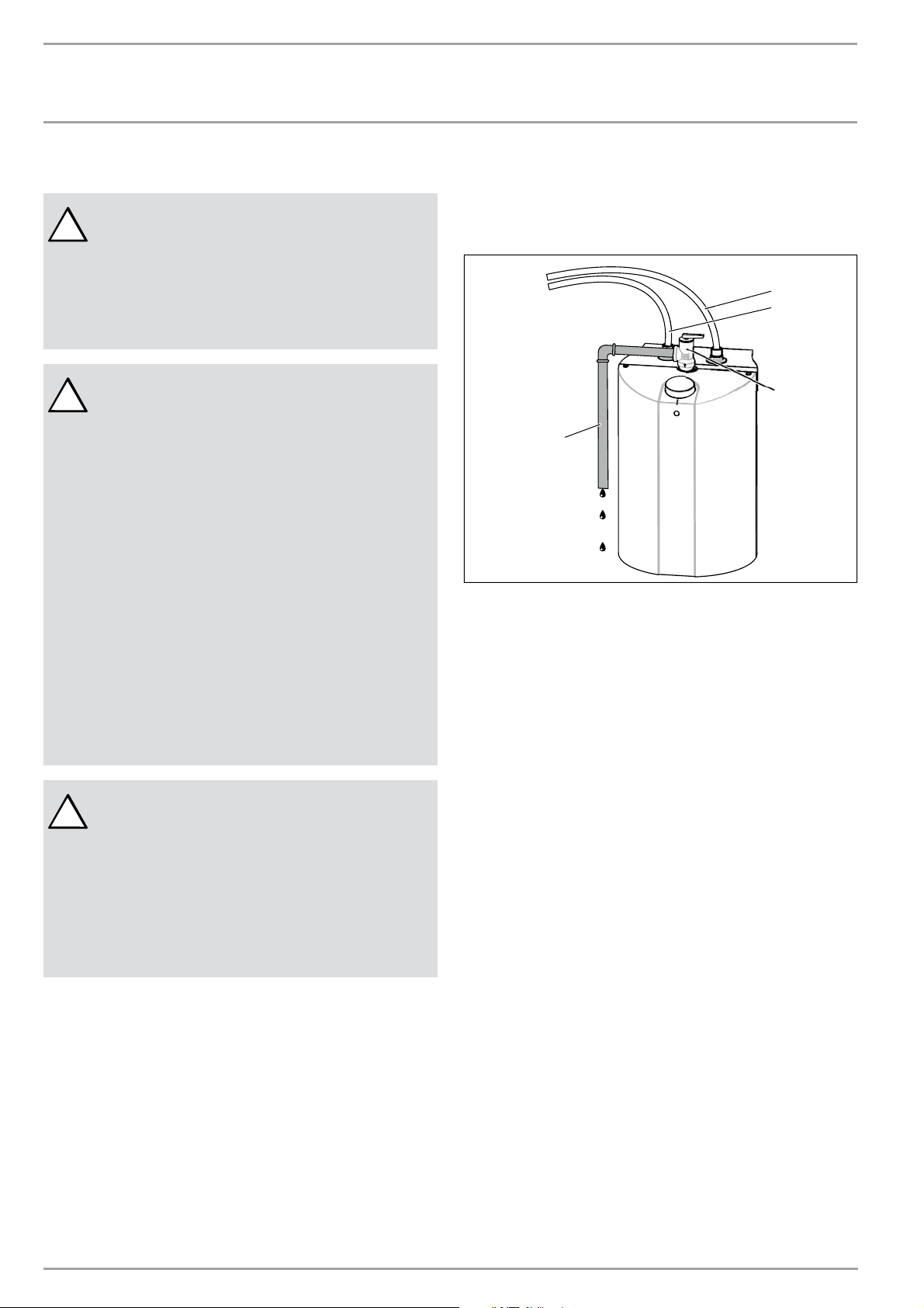
1. Cold water inlet
2. Hot water outlet
3. Pressure/temperature relief valve
4. Discharge pipe
Install a discharge pipe from the relief valve terminating
at a sink or drain.
DO NOT CAP OR THREAD THE END OF THE DISCHARGE
PIPE, IT MUST BE UNOBSTRUCTED AND FULL SIZE.
The P & T valve is certifi ed by a nationally recognized
test laboratory that maintains periodic inspection of the
listed equipment, and meets the requirements for re-
lief valves and automatic shut-off devices for hot water
supply systems ANSI 121.22-1979.
The P & T valve is marked with a maximum pressure,
which does not exceed the maximum working pressure
of the water heater (150 PSI).
Install the P & T valve into the threaded opening and
orient the tubing so that discharge will exit within 6”
above or at any distance below the structural fl oor, and
cannot contact any live electrical part.
THE DISCHARGE PIPE
1. Must not be smaller in size than the outlet pipe
size of the valve, or have reducing couplings.
2. Must not be plugged or blocked.
3. Must be of material suitable for hot water.
4. Must not be over fi fteen feet (15´) in length.
5. Must not have more than two elbows.
6. Must terminate at an adequate drain.
Loading ...
Loading ...
Loading ...