
1000W Pure Sine Wave Power Inverter
Onduleur sinusoïdal 1000W
Instruction Manual / Manuel d’instructions
Model / Modèle: FIVBDP10A

1
Welcome
English
Thank you and congratulations for purchasing this Furrion
®
1000W Pure Sine Wave Power
Inverter. Before operating your new product, please read these instructions carefully. This
instruction manual contains information for safe use, installation and maintenance of the
product.
Please keep this instruction manual in a safe place for future reference. This will ensure safe
use and reduce the risk of injury. Be sure to pass on this manual to new owners of this product.
The manufacturer does not accept responsibility for any damages as a result of not following
these instructions.
If you have any further questions regarding our products, please contact us at
supportfurrion.com

2
Contents
English
Welcome ............................................................................................1
Contents ............................................................................................2
Important Safety Instructions ............................................................3
General Safety Precautions ....................................................................................3
Precautions When Working with Batteries .............................................................3
About your Product ............................................................................4
Product Features .....................................................................................................4
Protective Features of the Inverter ......................................................................... 4
How your Inverter Works ........................................................................................4
Product Overview ..............................................................................5
Front Panel .............................................................................................................. 5
Rear Panel ............................................................................................................... 5
Installation ........................................................................................6
What’s in the Box ....................................................................................................6
Mounting the Inverter .............................................................................................6
Connecting to a Load ..............................................................................................7
Connecting to a Power Source ................................................................................ 9
Operation ...........................................................................................10
Care and Maintenance .......................................................................11
Fuse Replacement ..................................................................................................11
Disposal of your Old Product and Batteries ...........................................................11
Specifications ....................................................................................12
Troubleshooting .................................................................................13
Warranty ............................................................................................14

3
Important Safety Instructions
English
WARNING
● Before using the Inverter, read and
save the safety instructions.
IMPORTANT: THIS MANUAL CONTAINS
IMPORTANT INFORMATION REGARDING
SAFETY, OPERATION, MAINTENANCE AND
STORAGE OF THIS PRODUCT. BEFORE
USE, READ AND UNDERSTAND ALL
CAUTIONS, WARNINGS, INSTRUCTIONS
AND PRODUCTION LABELS, PLUS YOUR
VEHICLE’S BATTERY MANUFACTURER
GUIDELINES. FAILURE TO DO SO COULD
RESULT IN INJURY AND/OR PROPERTY
DAMAGE.
General Safety Precautions
● Do not expose the Inverter to rain,
snow, spray, bilge or dust. To reduce
risk of hazard, do not cover or obstruct
the ventilation openings. Do not
install the Inverter in a zero-clearance
compartment. Overheating may result.
● To avoid a risk of fire and electronic
shock. Make sure the existing wiring is
in good electrical condition, and the wire
size is not undersized.
● This equipment contains components
which can produce arcs or sparks. To
prevent fire or explosion do not install in
compartments containing batteries or
flammable materials or in locations which
require ignition protected equipment. This
includes any space containing gasoline-
powered machinery, fuel tanks, joints,
fittings, or other connection between
components of the fuel system.
● Make sure the wires equipped are in
good electrical condition. Do not operate
the inverter with wires punctured or
damaged.
● This is not a toy, keep away from children.
Precautions When Working with
Batteries
● If battery acid contacts skin or clothing,
wash immediately with soap and water.
If acid enters eye, immediately flood
eye with running cold water for at least
20 minutes and get medical attention
immediately.
● Never smoke or allow a spark or flame in
vicinity of battery.
● Do not let metal come in contact with the
top of the battery. The resulting spark or
short-circuit may cause an explosion.

4
About your Product
English
Product Features
● 1000 Watt continuous output for
electronic appliances
● High surge power up to 2500W
● Pure sine wave output to operate higher-
end electronic equipment
● Built in transfer switch with less than
20ms transfer time.
● Built in advance microprocessor
● Hard wire AC connection
● LED indicator with all operation status
● Low standby current
Protective Features of the
Inverter
OVER TEMPERATURE PROTECTION – If the
temperature inside the inverter is too high,
the unit will automatically shut down. The
inverter will automatically restart after the
temperature inside recovers to normal.
LOW BATTERY VOLTAGE PROTECTION - This
condition is not harmful to the inverter but
could damage the power source. The inverter
automatically shuts down when input voltage
drops to 10.5 volts.
OVER VOLTAGE PROTECTION – The inverter
will automatically shut down when the input
voltage exceeds 15.3 volts DC. Input voltage
exceeding 16 volts could damage the inverter.
OVERLOAD PROTECTION – The inverter will
automatically shut down when the continuous
draw exceeds rated watts.
SHORT CIRCUIT PROTECTION – The inverter
will shut down. Remove the short circuit and
restart inverter.
How your Inverter Works
The Furrion power inverter is an electronic
product that has been designed and built to
take low voltage DC (Direct Current) power
from your automobile or other low voltage
power supplies and convert it to standard
115 Volt AC (Alternating Current) power
similar to the current you have in your home.
This conversion allows you to use many of
your household appliances and electronic
products in automobiles, RVs, boats, tractors,
trucks and etc..

5
Product Overview
English
Front Panel
Circuit Breaker
LED Indicator
On/Off Switch
Strain Relief
Door of AC Wire
Compartment
AC Power Supply
Cord with 5-15P
Plug
Rear Panel
Remote Control
Port
Battery Negative
Terminal
Battery Positive
Terminal
Chassis Ground
Furrion
Communication
RJ25(6P6C) Port

6
Installation
English
What’s in the Box
Make sure you have all the following items
included in the packaging. If any item is
damaged or missing, contact your dealer.
− Power Inverter x 1
− Instruction Manual x 1
− Warranty Card x 1
Mounting the Inverter
The inverter has four slots in its mounting
bracket that allows the unit to be fastened
against a bulkhead, floor, wall or other flat
surface. (Fig. 1)
Fig. 1
The inverter can be operated in any position,
however, if it is to be mounted on a wall,
mount it horizontally (see Fig. 2 for correct
mounting direction) so that indicators,
switches, outlets and terminal blocks located
on the front panel are visible and accessible.
If inverter is to be installed in a moving
vehicle, it is strongly recommended that the
inverter be shock-mounted either on the
floor (in a clear, safe area) or on a secure flat
surface.
Fig. 2
The power inverter should be installed in
an environment that meets the following
requirements.
● DRY Do not allow water to drip on or
enter into the inverter.
● COOL Ambient air temperature should
be between 0°C and 40°C, the cooler the
better.
● SAFE Do not install the inverter
in a battery compartment or other
areas where volatile fumes may exist,
such as fuel storage areas or engine
compartments.
● VENTILATED Keep the inverter (25mm
at least) away from surrounding objects.
Ensure the ventilation area of the unit is
not obstructed.
● DUST Do not install the Inverter in dusty
environments. The dust can be inhaled
into the unit when the cooling fan is
working.
● FUSED A fuse must be applied between
the battery and the Inverter.
● CLOSE TO BATTERIES Avoid excessive
cable lengths. Do not install the Inverter
in the same compartment as batteries.
● Use the recommended wire lengths and
sizes.
● Do not mount the Inverter where it will
be exposed to the gases produced by the
battery. These gases are very corrosive,
and prolonged exposure will damage the
Inverter.

7
Installation
English
Connecting to a Load
WARNING
SHOCK HAZARD!
Before proceeding further, carefully
check that the Inverter is NOT connected
to any batteries, and that all wiring is
disconnected from any electrical sources.
Make sure the bypass AC input plug is
disconnected to any AC source.
Do not connect the output terminals of the
Inverter to an incoming AC source.
Make sure the power switch is in off
position before and after the installation.
Neutral Grounding:
The neutral conductor of the AC output circuit
of the inverter is automatically connected to
the safety ground during inverter operation.
This conforms to National Electrical Code
requirements that a derived AC source, such
as an inverter or generator, must have their
neutral conductors tied to ground in the
same way that the neutral conductor from
the utility is tied to ground at the AC breaker
panel. When AC utility power is present and
the inverter is in bypass mode, this neutral to
ground connection is not present. The utility
power neutral is only connected to ground at
the breaker panel.
Ground Fault Circuit Interrupters
(GFCI):
Recreational Vehicles Installations (for
North American approvals) will require GFCI
protection. All branch circuits connected
to the AC output hard wire should be GFCI
protected. Additional electrical codes may
require GFCI protection of certain receptacles
in residential installations.
While the pure sine wave output of the
inverter is equivalent to the waveform
provided by utilities, compliance with
UL standards requires Furrion to test
and recommend specific GFCI. Use only
GENERAL PROTECT GROUP INC, Type DG15
ground-fault circuit-interrupter receptacles.
Or AMERICAN ELECTRIC DEPOT INC, Type
G1501 ground-fault circuit-interrupter
receptacles. Other types may fail to operate
properly when connected to this unit.
Hard-wire Installation
The AC wiring compartment is located on the
front panel of the inverter.
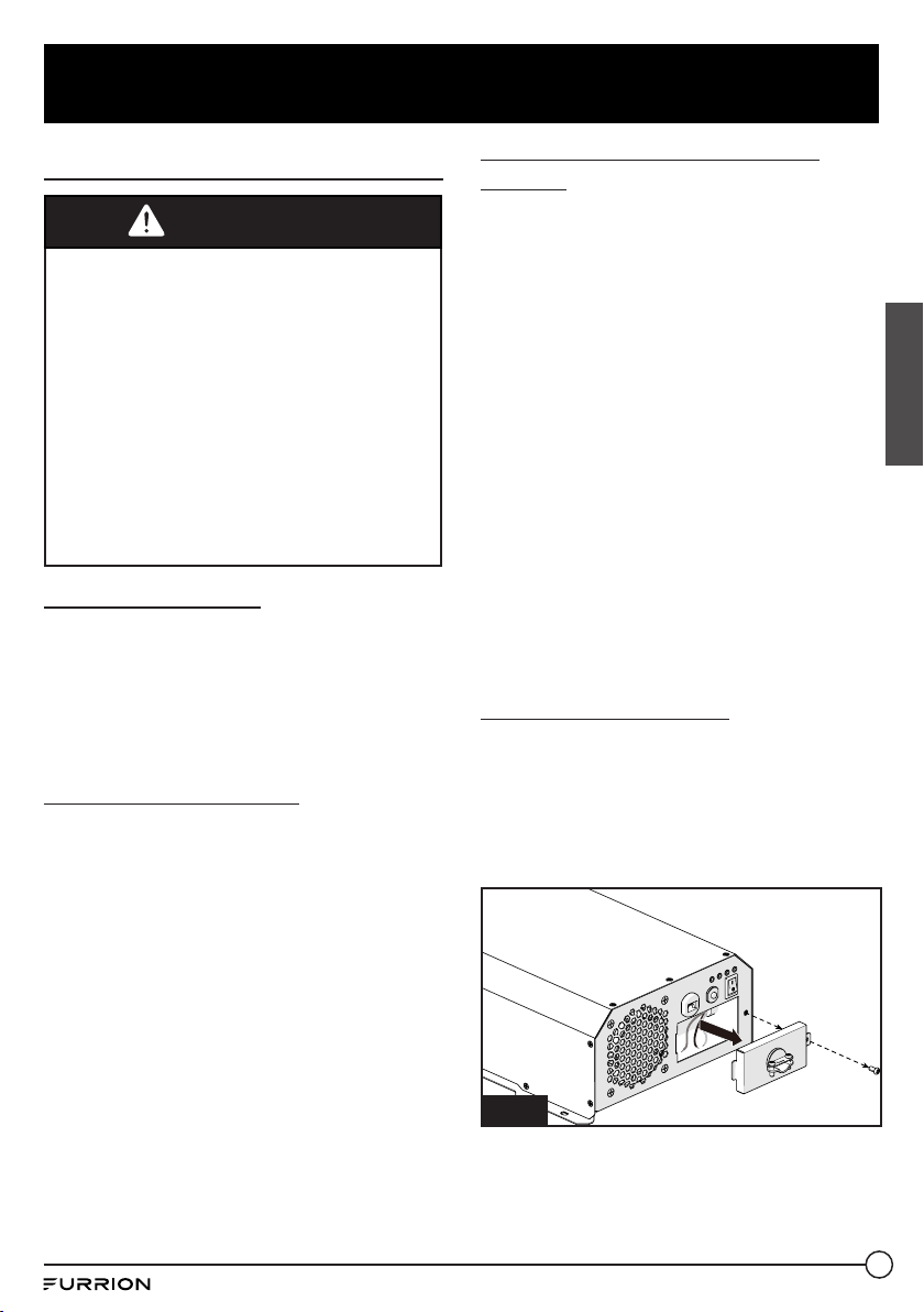
1. Remove the AC wiring compartment cover
to gain access to the AC output hard-wire
(pigtails leads). (Fig. 3)
Fig. 3
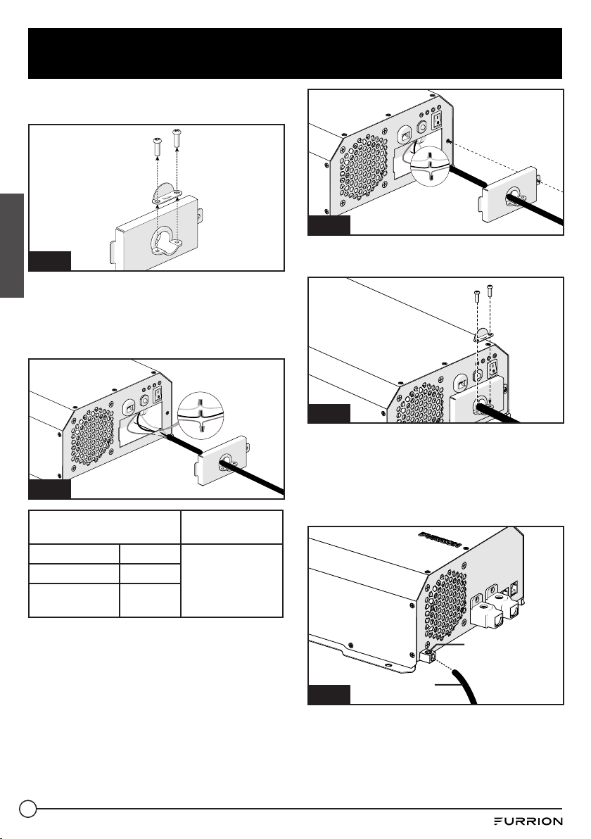
2. Remove the metal wire clip from the
cover. (Fig. 4)
Fig. 4

8
Installation
English
3. Connect the AC output wiring to the
inverter AC output hard-wire (pigtails
leads) by using wire connectors. Black to
black, white to white. (Fig. 5)
Fig. 5
AC Output Wiring
Wire Length/
Gauge
Line (L) Black
Within 25 feet /
AWG# 14~16
Neutral (N) White
Ground
Green or
Bare copper
4. Double check all connections to make
sure the wires are in correct position and
all wires are secured.
5. Wrap the wires and place into the
compartment. Replace the cover to
the inverter and secure with the screw
provided. (Fig. 6)
Fig. 6
6. Replace the wire clip and fix with 2 screws
provided. (Fig. 7)
Fig. 7
7. Using a /” hex wrench, loosen the
ground lug screw located on the mid left
side of the rear panel. Insert an 8AWG
copper wire from this lug to chassis
ground. Tighten the lug securely with
35inch-lbs torque maximum. (Fig. 8)
Ground lug
Fig. 8
8AWG
Ground wire

9
Installation
English
Connecting to a Power Source
CAUTION
● The power inverter must be connected
only to batteries with a nominal output
voltage of 12volts. The unit will not
operate from a 6 volt battery, and
will sustain permanent damage if
connected to a 24 volt battery.
● The input current of this inverter is
about 100A with full load, make sure
the battery could discharge over 100A
continuously.
● The battery should have a Cold
Cranking Amp more than 500A.
CAUTION
Loose connectors may cause overheated
wires and melted insulation. Check to
make sure you have not reversed the
polarity. Reverse polarity connection will
result in a blown fuse and may cause
permanent damage to the inverter.
Damage due to reverse polarity is not
covered by warranty.
WARNING
The installation of a fuse must be on the
positive cable. Failure to place a fuse on
“+”cables running between the Inverter
and battery may cause damage to the
inverter and will void warranty.
Furrion recommends the following cables for
an optimum inverter performance.
External FUSE and DC Cable Selection
Wire AWG
Capacity of
the fuse
Max distance between
inverter and the battery
#4 150A 10FT
The following recommendations should
always be followed while making connection
between the battery and the Inverter.
● The cables should be made of high quality
copper wiring, also keep the cable length
as short as possible.
● Cables should be of adequate gauge for
the length. The inverter performance will
decrease if the cables are not of adequate
gauge (too small or too long).
● Battery cable fusing - A fuse is required
by the National Electrical Code (NEC) to
protect the battery and cables, A UL listed
DC rated slow blow fuse must be installed
in positive battery cable, within 18 inches
of the battery.
● Make sure the terminal screws are tight
enough, max. 45inch-lbs torque for the
screws.
FUSE

10
Operation
English
To operate the inverter, turn it on by pressing the ON/OFF switch. The inverter is now ready to
deliver AC power to your loads. If you are loading several appliances, turn them on separately
after the inverter switch is on, this process is to avoid the power inverter from delivering the
starting current all at once to the loads.
The inverter can operate with and without being connected to a nominal 12V DC battery source
by using the bypass AC input mode. Plugging the attached AC power cord into a 120V power
source will result in an automatic bypass of the 12V DC power source. Disconnecting the 120V
input source will automatically transfer back to the nominal 12V DC source.
Controls and indicators
1
Yellow LED Indicates the inverter is activated.
2
Green LED Indicates the bypass AC input is activated.
3
Red LED Indicates the inverter is with overloading, over temperature,
low battery voltage, over battery voltage or output short circuit.
4
Green LED Indicates the inverter is operating normally.
2
1
3
4
NOTE: Press the ON/OFF button to restore when an error is encountered.

11
Care and Maintenance
English
Clean only with dry cloth. Do not clean the unit with strong chemical agents or abrasive
cleaners. Never spill liquid of any kind on the product. Do not allow residue or liquids to enter
any part of the appliance as this may cause risk of electrocution. Always disconnect from any
power source before cleaning.
Fuse Replacement
CAUTION: NO USER-SERVICEABLE COMPONENTS INSIDE. DO NOT ATTEMPT TO OPEN THE
INVERTER.
The inverter is equipped with a fuse that is located inside the inverter. Normally, the fuse will
not blow unless a serious problem occurs such as high voltage and high temperature inside the
inverter. Please DO NOT replace the fuse yourself, we recommend you contact a technician to
find and fix the problems.
Disposal of your Old Product and Batteries
The inverter is designed and manufactured with high quality materials and components, which
can be recycled and reused.
Please observe the local regulations regarding the disposal of packaging materials, exhausted
batteries and old equipment.

12
Specifications
English
Specifications
Battery Voltage 10.5V~15VDC
AC Bypass Input 100~120Vac
Output Voltage 115 ±5 Vac
Output Frequency 60±1Hz
Output Waveform Pure Sine Wave
Continuous Rated Power 1000w
Surge Output Power (2 Seconds) 2500w
Maximum Peak Efficiency 88%
Circuit Breaker 15A
Bypass Transfer Time <20ms
Transfer Relay Rating 16A
Low Battery Protection YES
Over Voltage Protection YES
Over Load Protection YES
Over Temperature Protection YES
Battery Reverse Protection YES, By Fuse
AC Output Short Circuit Protection YES
Safety Standard ETL Listed To UL 458 and CSA C22.2 NO.107.1
EMC Standards Meet FCC Part 15 Class B
Operation Temperature 0°C~40°C/ 32°F~104°F
Operation Humidity <90% RH Non-condensing
Storage Temp., Humidity -30°C~+70°C/-22°F~+158°F, 10~95% RH
Dimension (L*W*H) 435*236*112mm
Net. Weight 5.05kg
Gross Weight 5.5kg

13
Troubleshooting
English
TROUBLE/SYMPTOM POSSIBLE CAUSES SOLUTION
No AC output
(Red LED lit, Yellow LED
not lit)
Low battery voltage Recharge or replace battery
Over battery voltage Check the battery voltage
Output short circuit protection
Check the output, remove the short
circuit and restart the inverter by
turning the switch off/on
Inverter shut down by overload
Remove or reduce load, restart the
inverter by turning the switch off/on
Inverter overheat thermal
shutdown
Remove or reduce load, wait for
inverter to cool
No AC output
(Red & Green LED not lit)
DC cable loosen or Inverter fuses
open
Check cable connection Or contact
technical support
Appliance won’t start Excessive start-up load
If appliance does not start, then
appliance is drawing excessive wattage
and will not work with inverter
Refrigerator won’t start
Excessive start-up load
Check the load rating (the startup
power is over 8 times of the rating
power)
The battery cable or the output
wiring cable are not the correct
size
Check the cables, and use the correct
size of the cable
The cold cranking amperage
of the battery is lower than
the starting load amperage
requirement
Check the battery, and use the correct
battery

14
English
Warranty
Furrion warrants for a period of 1 year from date of retail purchase by the original end-use
purchaser, that this product, when delivered to you in new condition, in original packaging,
from a Furrion authorized reseller and used in normal conditions, is free from any defects
in manufacturing, materials, and workmanship. In case of such defect, Furrion shall replace
or repair the product at no charge to you. This warranty does not cover: products where the
original serial numbers have been removed, altered or cannot readily be determined; damage
or loss caused by accident, misuse, abuse, neglect, product modification, failure to follow
instructions in instruction manual, commercial or industrial use; damage or loss caused to the
decorative surface of product; to any data, software or information; and normal wear and tear.
This warranty only protects the original end-user (“you”) and is not transferable; any attempt to
transfer this warranty shall make it immediately void. This warranty is only valid in the country
of purchase.
THIS WARRANTY AND REMEDIES SET FORTH ABOVE ARE EXCLUSIVE AND IN LIEU OF ALL
OTHER WARRANTIES, REMEDIES AND CONDITIONS, WHETHER ORAL OR WRITTEN, EXPRESS
OR IMPLIED. FURRION SPECIFICALLY DISCLAIMS ANY AND ALL IMPLIED WARRANTIES,
INCLUDING, WITHOUT LIMITATION, WARRANTIES OF MERCHANTABILITY AND FITNESS FOR
A PARTICULAR PURPOSE. IF FURRION CANNOT LAWFULLY DISCLAIM IMPLIED WARRANTIES
UNDER THIS LIMITED WARRANTY, ALL SUCH WARRANTIES, INCLUDING WARRANTIES OF
MERCHANTABILITY AND FITNESS FOR A PARTICULAR PURPOSE ARE LIMITED IN DURATION
TO THE DURATION OF THIS WARRANTY.
No Furrion reseller, agent, or employee is authorized to make any modification, extension, or
addition to this warranty.

15
English
FURRION IS NOT RESPONSIBLE FOR DIRECT, INDIRECT, SPECIAL, INCIDENTAL OR
CONSEQUENTIAL DAMAGES RESULTING FROM ANY BREACH OF WARRANTY OR CONDITION,
OR UNDER ANY OTHER LEGAL THEORY, INCLUDING BUT NOT LIMITED TO LOST PROFITS,
DOWNTIME, GOODWILL, DAMAGE TO OR REPLACEMENT OF ANY EQUIPMENT OR PROPERTY,
ANY COSTS OF RECOVERING, REPROGRAMMING, OR REPRODUCING ANY PROGRAM OR DATA
STORED IN OR USED WITH FURRION PRODUCTS. FURRION’S TOTAL LIABILITY IS LIMITED
TO THE REPAIR OR REPLACEMENT OF THIS PRODUCT PURSUANT TO THE TERMS OF THIS
WARRANTY.
SOME STATES DO NOT ALLOW THE EXCLUSION OR LIMITATION OF INCIDENTAL OR
CONSEQUENTIAL DAMAGES OR EXCLUSIONS OR LIMITATIONS ON THE DURATION OF IMPLIED
WARRANTIES OR CONDITIONS, SO THE ABOVE LIMITATIONS OR EXCLUSIONS MAY NOT APPLY
TO YOU. THIS WARRANTY GIVES YOU SPECIFIC LEGAL RIGHTS, AND YOU MAY ALSO HAVE
OTHER RIGHTS THAT VARY BY STATE OR (WHERE APPLICABLE IN THE COUNTRIES WHERE
FURRION HAS NON-US/CANADIAN AUTHORIZED DEALERS) COUNTRY. NO ACTION OR CLAIM
TO ENFORCE THIS WARRANTY SHALL BE COMMENCED AFTER THE EXPIRATION OF THE
WARRANTY PERIOD.
Keep your receipt, delivery slip, or other appropriate payment record to establish the warranty
period. Service under this warranty must be obtained by contacting Furrion at
Product features or specifications as described or illustrated are subject to change without
notice.
Warranty

16
Bienvenue
Français
Merci et félicitations pour l’achat de cet onduleur sinusoïdal 1000W de Furrion
®
. Avant utiliser
votre nouvel appareil, veuillez lire ces consignes attentivement. Le présent guide d’utilisation
contient des informations permettant l’utilisation, l’installation et l’entretien en toute sécurité
de l’appareil.
Veuillez conserver le présent guide d’utilisation en lieu sûr pour vous y référer ultérieurement,
afin d’assurer votre sécurité et de réduire les risques de blessure. Veuillez aussi remettre le
présent manuel à tout nouveau propriétaire de cet appareil.
Le fabricant décline toute responsabilité en cas de dommages résultant du non-respect de ces
instructions.
Si vous avez des questions sur nos produits, veuillez nous contacter: [email protected]

17
Contenu
Français
Bienvenue ..........................................................................................16
Contenu .............................................................................................17
Consignes importantes sur la sécurité ..............................................18
Précautions générales de sécurité ......................................................................... 18
Mesures de précaution lors de l’utilisation de batteries ........................................18
À propos de votre produit ..................................................................19
Caractéristiques du produit ....................................................................................19
Caractéristiques de protection de l’onduleur ......................................................... 19
Fonctionnement de l’onduleur ................................................................................19
Présentation du produit .....................................................................20
Panneau avant ......................................................................................................... 20
Panneau arrière ......................................................................................................20
Installation ........................................................................................21
Contenu de la boîte .................................................................................................21
Montage de l’onduleur ............................................................................................21
Connexion à une charge ..........................................................................................22
Raccordement à une source d’alimentation ...........................................................24
Utilisation ..........................................................................................25
Soin et entretien ................................................................................26
Remplacement de fusible .......................................................................................26
Mise au rebut de votre ancien produit et des batteries ..........................................26
Caractéristiques ................................................................................27
Dépannage .........................................................................................28
Garantie .............................................................................................29

18
Consignes importantes sur la sécurité
Français
ATTENTION
● Avant d’utiliser l’onduleur, lisez et
conservez les consignes de sécurité.
IMPORTANT: CE MANUEL CONTIENT
DES INFORMATIONS IMPORTANTES
CONCERNANT LA SÉCURITÉ, LE
FONCTIONNEMENT, L’ENTRETIEN ET
L’ENTREPOSAGE DE CE PRODUIT. AVANT
TOUTE UTILISATION, LISEZ ET COMPRENEZ
L’ENSEMBLE DES MISES EN GARDE,
AVERTISSEMENTS, INSTRUCTIONS ET
ÉTIQUETTES DE PRODUCTION, AINSI QUE
LES CONSIGNES DU FABRICANT DE LA
BATTERIE DE VOTRE VÉHICULE. TOUT
MANQUEMENT À CET ÉGARD POURRAIT
ENTRAÎNER DES BLESSURES ET/OU DES
DOMMAGES MATÉRIELS.
Précautions générales de
sécurité
● N’exposez pas l’onduleur à la pluie, à la
neige, aux embruns, à la boue ou à la
poussière. Pour réduire les risques, ne
pas couvrir ni obstruer les ouvertures
de ventilation. N’installez pas l’onduleur
dans un compartiment sans dégagement.
L’unité pourrait alors surchauffer.
● Pour éviter les risques d’incendie et
d’électrocution. Assurez-vous que le
câblage existant est en bon état et que le
calibre du fil n’est pas trop petit.
● Cet équipement contient des composants
qui peuvent produire des arcs ou des
étincelles. Pour éviter les incendies ou
les explosions, n’installez pas l’unité
dans des compartiments contenant
des batteries ou des matériaux
inflammables ni dans des endroits
nécessitant un équipement protégé
contre l’inflammation. Cela comprend
tout espace contenant des machines à
essence, des réservoirs de carburant,
des joints, des raccords ou tout autre
raccordement entre les composants du
système d’alimentation en carburant.
● Assurez-vous que les câbles sont en bon
état. N’utilisez pas l’onduleur si des fils
sont perforés ou endommagés.
● Cet appareil n’est pas un jouet; gardez-le
hors de portée des enfants.
Mesures de précaution lors de
l’utilisation de batteries
● Si l’acide de la batterie entre en contact
avec la peau ou les vêtements, lavez-
les immédiatement avec du savon et de
l’eau. Si l’acide entre en contact avec vos
yeux, rincez-les immédiatement à l’eau
froide pendant au moins 20minutes et
consultez un médecin immédiatement.
● Ne fumez pas et écartez la batterie de
toute source d’étincelle ou de flamme.
● Ne laissez pas le métal entrer en contact
avec le dessus de la batterie. L’étincelle
ou le court-circuit ainsi produit pourrait
causer une explosion.

19
À propos de votre produit
Français
Caractéristiques du produit
● Convient au réfrigérateur Furrion de
14pi³
● Puissance continue de 1000watts pour
les appareils électroniques
● Tension de crête pouvant atteindre
2500W
● Sortie sinusoïdale convenant à
l’équipement électronique haut de
gamme
● Microprocesseur de pointe intégré
● Raccordement CA câblé facile à installer
● Témoin DEL indiquant tous les états de
fonctionnement
● Faible courant de veille
Caractéristiques de protection
de l’onduleur
PROTECTION CONTRE LA SURCHAUFFE - Si
la température à l’intérieur de l’onduleur est
trop élevée, l’unité s’éteint automatiquement.
L’onduleur redémarre automatiquement
lorsque la température intérieure revient à la
normale.
PROTECTION CONTRE LA TENSION DE
BATTERIE FAIBLE - Cette condition ne nuit
pas à l’onduleur, mais pourrait endommager
la source d’alimentation. L’onduleur s’arrête
automatiquement lorsque la tension d’entrée
chute à 10,5volts.
PROTECTION CONTRE LES SURTENSIONS -
L’onduleur s’éteint automatiquement lorsque
la tension d’entrée dépasse 15,3volts CC.
Une tension d’alimentation de plus de 16V
pourrait endommager l’onduleur.
PROTECTION CONTRE LES SURCHARGES -
L’onduleur s’éteint automatiquement lorsque
l’appel de courant dépasse la puissance
nominale en watts.
PROTECTION CONTRE LES COURTS-
CIRCUITS - L’onduleur s’arrête. Corrigez le
court-circuit et redémarrez l’onduleur.
Fonctionnement de l’onduleur
L’onduleur Furrion est un produit
électronique conçu et construit pour
transformer l’alimentation CC (courant
continu) basse tension de votre véhicule ou
d’une autre source d’alimentation basse
tension à une alimentation 115V CA (courant
alternatif) standard semblable à celle de
votre domicile. Cette conversion vous permet
d’utiliser vos appareils ménagers et produits
électroniques dans un véhicule, un VR, une
embarcation, un tracteur, un camion, etc.

20
Présentation du produit
Français
Panneau avant
Disjoncteur
Témoin DEL
Interrupteur
marche/arrêt
Serre-câble
Porte du
compartiment de
câble CA
Cordon d’alimentation
CA avec fiche NEMA
5-15P
Panneau arrière
Port de commande
à distance
Borne négative de
la batterie
Borne positive de
batterie
Châssis au sol
Port de RJ25(6P6C)
de communication
de Furrion

21
Installation
Français
Contenu de la boîte
Assurez-vous que tous les éléments suivants
sont inclus dans l’emballage. Si un article est
endommagé ou manquant, contactez votre
revendeur.
− Onduleur x 1
− Manuel d’instructions x 1
− Carte de garantie x 1
Montage de l’onduleur
L’onduleur dispose de quatre fentes dans
son support de montage, ce qui permet
d’installer l’unité sur une cloison, un
plancher, un mur ou sur toute autre surface
plane. (Fig. 1)
Fig. 1
L’onduleur peut être utilisé dans n’importe
quelle position; toutefois, s’il est monté sur
un mur, montez-le à l’horizontale (Voir la
Fig. 2 pour la direction de montage correcte)
afin que les témoins, interrupteurs, prises et
borniers situés sur le panneau avant soient
visibles et accessibles. Si l’onduleur doit être
installé dans un véhicule en mouvement, il
est fortement recommandé de le fixer au
plancher (dans un endroit sûr et sécuritaire)
ou sur une surface plane et stable.
Fig. 2
L’onduleur doit être installé dans un
environnement répondant aux exigences
suivantes.
● SEC Ne laissez pas l’eau s’égoutter ou
s’infiltrer dans l’onduleur.
● FRAIS La température de l’air ambiant
doit être comprise entre 0°C et 40°C;
choisissez l’endroit le plus frais possible.
● SÉCURITAIRE N’installez pas l’onduleur
dans un compartiment de batteries ou
dans un autre endroit où des émanations
volatiles peuvent se produire, telles que
des zones de stockage de carburant ou le
compartiment moteur.
● VENTILÉ Maintenez une distance
minimale de 25mm entre l’onduleur et
les objets environnants. Assurez-vous
que la zone de ventilation de l’appareil
n’est pas obstruée.
● POUSSIÈRE N’installez pas l’onduleur
dans des environnements poussiéreux.
La poussière peut être aspirée dans
l’appareil lorsque le ventilateur de
refroidissement fonctionne.
● PROTECTION PAR FUSIBLE - Un
fusible doit être posé entre la batterie et
l’onduleur.
● PRÈS DES BATTERIES - Évitez
les longueurs de câble excessives.
N’installez pas l’onduleur dans le même
compartiment que les batteries.
● Utilisez les longueurs et les calibres de
fils recommandés.
● Ne montez pas l’onduleur là où il sera
exposé aux gaz produits par la batterie.
Ces gaz sont très corrosifs et une
exposition prolongée endommagera
l’onduleur.
22
Installation
Français
Connexion à une charge
ATTENTION
RISQUE DE CHOC!
Avant d’aller plus loin, assurez-vous que
l’onduleur n’est connecté à AUCUNE
batterie et que tout le câblage est
déconnecté de toute source électrique.
Assurez-vous que la prise d’entrée AC de
dérivation est débranchée de toute source
CA.
Ne connectez pas les bornes de sortie de
l’onduleur à une source CA entrante.
Assurez-vous que l’interrupteur
d’alimentation est en position fermée avant
et après l’installation.
Mise à la masse CA:
La mise à la masse de l’entrée CA doit être
raccordée à la masse entrante des sources
CA et la mise à la masse de la sortie CA doit
se raccorder au point de mise à la masse des
charges. (Par exemple, un bus de mise à la
masse du panneau de distribution).
Mise à la terre neutre:
Le conducteur neutre du circuit de sortie
CA de l’onduleur est automatiquement
connecté à la terre de sécurité pendant
le fonctionnement du variateur. Ceci est
conforme aux exigences du National
Electrical Code stipulant qu’une source
CA dérivée, telle qu’un onduleur ou une
génératrice, doit avoir ses conducteurs
neutres attachés à la terre de la même
manière que le conducteur neutre du secteur
est relié à la terre au panneau de disjoncteur
CA. Lorsque l’alimentation secteur est
présente et que l’onduleur est en mode
bypass, cette connexion neutre à terre n’est
pas présente. Le neutre d’alimentation
secteur est uniquement connecté à la masse
sur le panneau de disjoncteur.
Disjoncteurs de fuite à la terre
(GFCI):
Les installations dans des véhicules
récréatifs (pour les approbations nord-
américaines) nécessitent une protection par
GFCI. Tous les circuits branchés au câble de
sortie CA doivent être protégés par GFCI. Des
codes électriques supplémentaires peuvent
exiger la protection GFCI de certaines prises
pour les installations résidentielles.
Lorsque la sortie sinusoïdale de l’onduleur
correspond à la forme d’onde des services
publics, la conformité aux normes UL
exige que Furrion teste et recommande un
GFCI spécifique. N’utilisez que des prises
pour disjoncteur de fuite à la terre du type
DG15, GENERAL PROTECT GROUP INC. Ou
des prises pour disjoncteur de fuite à la
terre du type G1501 AMERICAN ELECTRIC
DEPOT INC. D’autres types peuvent ne pas
fonctionner correctement lorsqu’ils sont
utilisés avec cet appareil.
Installation du câblage
Le compartiment de câblage CA est situé sur
le panneau avant de l’onduleur.
1. Retirez le couvercle du compartiment
de câblage CA pour accéder au câble de
sortie CA (raccords en queue de cochon).
(Fig. 3)
Fig. 3
23
Installation
Français
2. Retirez l’attache métallique du couvercle.
(Fig. 4)
Fig. 4
3. Branchez le câble de sortie CA sur le
câble de sortie CA de l’onduleur (raccords
en queue de cochon) à l’aide des
connecteurs. Noir à noir, blanc à blanc.
(Fig. 5)
Fig. 5
Câblage de sortie CA
Longueur/calibre
de fil
Conducteur (L) Noir
25pieds ou
moins: calibres
14-16
Neutre (N) Blanc
Masse
Vert ou
cuivre nu
4. Vérifiez tous les raccordements pour vous
assurer que les fils sont correctement et
solidement branchés.
5. Enveloppez les fils et placez-les dans le
compartiment. Replacez le couvercle sur
l’onduleur et fixez-le avec la vis fournie.
(Fig. 6)
Fig. 6
6. Remplacez l’attache et fixez-la à l’aide
des 2vis fournies. (Fig. 7)
Fig. 7
7. À l’aide d’une clé hexagonale de 5/32
po, desserrez la vis de la cosse de terre
située sur le côté gauche du panneau
arrière. Insérez un fil de cuivre 8AWG de
cette cosse à la masse du châssis. Serrez
fermement la cosse. (Fig. 8)
Cosse de terre
Fig. 8
Fil de masse
de calibre8

24
Installation
Français
Raccordement à une source
d’alimentation
MISE EN GARDE
● L’onduleur doit être connecté
uniquement aux batteries ayant
une tension de sortie nominale de
12volts. L’unité ne fonctionnera pas
avec une batterie de 6volts, et sera
endommagée en permanence si elle
est raccordée à une batterie de 24volts.
● Le courant d’entrée de cet onduleur
est d’environ 100A à pleine charge.
Assurez-vous que la batterie peut
décharger plus de 100A en continu.
● La batterie doit fournir plus de 500A de
démarrage à froid.
MISE EN GARDE
Des connecteurs desserrés peuvent
provoquer une surchauffe des fils et
faire fondre l’isolation. Assurez-vous que
vous n’avez pas inversé la polarité. Une
inversion de polarité grillera le fusible
et risque de causer des dommages
permanents à l’onduleur. Les dommages
causés par l’inversion de polarité ne sont
pas couverts par la garantie.
ATTENTION
L’installation d’un fusible doit être sur
le câble positif. Si vous ne placez pas un
fusible sur le câble «+» entre l’onduleur
et la batterie, vous risquez d’endommager
l’onduleur et d’annuler la garantie.
Pour assurer une performance optimale
de l’onduleur, Furrion recommande les
câbles suivants. Reportez-vous à la section
«Annexe» pour choisir la longueur et la
capacité de câble appropriées.
Sélection du fusible et du câble CC
Calibre
du fil
Capacité
du fusible
Distance maximale entre
l’onduleur et la batterie
#4 150A 10FT
Respectez toujours les recommandations
suivantes pour les raccordements entre la
batterie et l’onduleur.
● Les câbles doivent de cuivre de haute
qualité; n’oubliez pas d’utiliser le câble le
plus court possible.
● Les câbles doivent être de calibre adéquat
pour la longueur. Les performances de
l’onduleur diminuent si les câbles ne sont
pas d’un calibre adéquat (trop petit ou
trop long).
● Fusible du câble de batterie - Le Code
national de l’électricité (NEC) exige
la pose d’un fusible pour protéger la
batterie et les câbles. Un fusible à fusion
lente homologué UL doit être installé sur
le câble positif de la batterie, à moins de
18pouces de la batterie.
● Assurez-vous que les vis des bornes
sont suffisamment serrées, un couple de
45po-lb pour les vis.
FUSE

25
Utilisation
Français
Pour utiliser l’onduleur, allumez-le en appuyant sur l’interrupteur marche/arrêt. L’onduleur
est maintenant prêt à fournir une alimentation CA à vos appareils. Si vous alimentez plusieurs
appareils, allumez-les séparément après avoir allumé l’onduleur. Cette manière d’agir
empêche que l’onduleur alimente le démarrage de tous les appareils simultanément.
L’onduleur peut fonctionner avec et sans être connecté à une source de batterie nominale
de 12 V CC en utilisant le mode d’entrée AC bypass. En branchant le cordon d’alimentation
secteur connecté dans une source d’alimentation de 120 V, vous obtiendrez une dérivation
automatique de la source d’alimentation 12 V CC. La déconnexion de la source d’entrée 120 V
sera automatiquement renvoyée à la source nominale de 12 V CC.
Commandes et témoins
1
DEL jaune Indique que l’onduleur est activé.
2
DEL verte Indique que la dérivation d’entre CA est activée.
3
DEL rouge
Indique que l’onduleur présente une surcharge ou une surchauffe,
que la tension de la batterie est faible, qu’elle fournit une tension trop
élevée ou qu’il y a un court-circuit à la sortie.
4
DEL verte Indique que l’onduleur fonctionne normalement.
2
1
3
4
REMARQUE: APPUYEZ SUR LE BOUTON MARCHE/ARRÊT POUR RÉINITIALISER L’APPAREIL
APRÈS UNE ERREUR.

26
Soin et entretien
Français
Nettoyez uniquement avec un chiffon sec. Ne nettoyez pas l’unité avec des agents chimiques
puissants ou des nettoyants abrasifs. Ne versez jamais un liquide quelconque sur le produit. Ne
laissez aucun résidu ou liquide pénétrer dans l’appareil, car cela pourrait entraîner un risque
d’électrocution. Toujours débrancher de toute source d’alimentation avant de nettoyer.
Remplacement de fusible
MISE EN GARDE: AUCUN COMPOSANT RÉPARABLE PAR L’UTILISATEUR À L’INTÉRIEUR.
N’ESSAYEZ PAS D’OUVRIR L’ONDULEUR.
L’onduleur est équipé d’un fusible situé à l’intérieur de l’onduleur. Normalement, le fusible ne
soufflera pas à moins qu’un problème sérieux se produise tel que la haute tension et la haute
température à l’intérieur de l’onduleur.
Tension et température élevées à l’intérieur de l’onduleur. Veuillez NE PAS remplacer le fusible
vous-même. Nous vous recommandons de contacter un technicien pour trouver et régler les
problèmes.
Mise au rebut de votre ancien produit et des batteries
L’onduleur est conçu et fabriqué avec des matériaux et des composants de haute qualité, qui
peuvent être recyclés et réutilisés.
Veuillez respecter les réglementations locales concernant la mise au rebut des matériaux
d’emballage, des piles usagées et de l’ancien équipement.

27
Caractéristiques
Français
Caractéristiques
Tension de batterie
10.5V~15VDC
Dérivation d’entrée CA
100~120Vac
Tension de sortie
115 ±5 Vac
Fréquence de sortie
60±1Hz
Forme d’onde de sortie
Pure Sine Wave
Puissance nominale continue
1000w
Puissance de sortie de crête (2secondes)
2500w
Efficacité maximale
88%
Disjoncteur
15A
Délai de transfert de dérivation
<20ms
Valeur du relais de transfert
16A
Protection de batterie faible
YES
Protection contre les surtensions
YES
Protection contre les surcharges
YES
Protection contre les températures
excessives
YES
Protection contre l’inversion de polarité
YES, By Fuse
Protection contre les courts-circuits à la
sortie CA
YES
Norme de sécurité
ETL Listed To UL 458 and CSA C22.2 NO.107.1
Normes CEM
Meet FCC Part 15 Class B
Température de fonctionnement
0°C~40°C/ 32°F~104°F
Humidité de fonctionnement
<90% RH Non-condensing
Température, humidité d’entreposage
-30°C~+70°C/-22°F~+158°F, 10~95% RH
Dimensions (long. x larg. x haut.)
435*236*112mm
Poids net
5.05kg
Poids brut
5.5kg

28
Dépannage
Français
PROBLÈME/SYMPTÔME CAUSES POSSIBLES SOLUTION
Pas de sortie CA
(DEL rouge allumée, DEL
jaune éteinte)
Tension de batterie faible Rechargez ou remplacez la batterie
Surtension de la batterie Vérifiez la tension de la batterie
Protection contre les courts-
circuits à la sortie
Vérifiez la sortie, réparez le court-
circuit et redémarrez l’onduleur en
éteignant/allumant l’interrupteur
Onduleur mis hors tension par
une surcharge
Retirez ou réduisez la charge, puis
redémarrez l’onduleur en éteignant/
allumer l’interrupteur
Arrêt de l’onduleur par la
protection thermique
Retirez ou réduisez la charge; attendez
que l’onduleur refroidisse
Pas de sortie CA
(Les DEL rouge et verte ne
s’allument pas)
Câble CC desserré ou fusibles de
l’onduleur grillés
Vérifiez le raccordement du câble ou
contactez le soutien technique
L’appareil ne démarre pas Charge de démarrage excessive
Si l’appareil ne démarre pas, il
consomme une puissance excessive et
ne fonctionnera pas avec l’onduleur
Le réfrigérateur ne
démarre pas
Charge de démarrage excessive
Vérifiez la capacité de charge
(la puissance de démarrage est
supérieure à 8fois la puissance
nominale)
Le câble de la batterie ou le câble
de sortie ne sont pas du bon
calibre
Vérifiez les câbles et utilisez un câble
de bon calibre
L’ampérage de démarrage à
froid de la batterie est inférieur à
l’exigence d’ampérage de charge
de démarrage
Vérifiez la batterie et utilisez la bonne
batterie

29
Français
Garantie
FURRION GARANTIT, PENDANT UNE PÉRIODE D’UN AN À PARTIR DE LA DATE DE L’ACHAT AU
DÉTAIL PAR L’UTILISATEUR FINAL INITIAL, QUE CE PRODUIT, S’IL EST LIVRÉ À L’ÉTAT NEUF,
DANS SON EMBALLAGE ORIGINAL, PAR UN REVENDEUR FURRION AUTORISÉ ET UTILISÉ EN
CONDITIONS NORMALES, EST LIBRE DE TOUT DÉFAUT DE FABRICATION, DE MATÉRIEL ET
DE MAIN-D’ŒUVRE. EN CAS DE DÉFAUT, FURRION S’ENGAGE À REMPLACER OU À RÉPARER
LE PRODUIT GRATUITEMENT. CETTE GARANTIE EXCLUT CE QUI SUIT : PRODUITS DONT LE
NUMÉRO DE SÉRIE ORIGINAL A ÉTÉ ENLEVÉ, MODIFIÉ OU RENDU ILLISIBLE, LES DOMMAGES
OU LES PERTES CAUSÉS PAR UN ACCIDENT, UNE MAUVAISE UTILISATION, LA NÉGLIGENCE,
LA MODIFICATION DU PRODUIT OU LE MANQUEMENT À SUIVRE LES CONSIGNES DU GUIDE
DE L’UTILISATEUR, L’UTILISATION COMMERCIALE OU INDUSTRIELLE, LES DOMMAGES OU
LES PERTES CAUSÉES À LA SURFACE DÉCORATIVE DU PRODUIT, LES DOMMAGES CAUSÉS
AUX DONNÉES, LOGICIELS OU RENSEIGNEMENTS, AINSI QUE L’USURE NORMALE. LA
PRÉSENTE GARANTIE PROTÈGE UNIQUEMENT L’UTILISATEUR FINAL INITIAL («VOUS»),
ET NE PEUT ÊTRE CÉDÉE À QUICONQUE. TOUTE TENTATIVE DE CESSION DE LA PRÉSENTE
GARANTIE AURA POUR EFFET SON ANNULATION IMMÉDIATE. LA PRÉSENTE GARANTIE EST
UNIQUEMENT VALIDE DANS LE PAYS D’ACHAT.
LA PRÉSENTE GARANTIE ET LES RECOURS PRÉCÉDEMMENT DÉFINIS SONT EXCLUSIFS ET
REMPLACENT TOUTES LES AUTRES RECOURS, GARANTIES ET CONDITIONS, QU’ILS SOIENT
ORAUX OU ÉCRITS, EXPLICITES OU IMPLICITES. FURRION DÉCLINE SPÉCIFIQUEMENT
TOUTES LES GARANTIES IMPLICITES, Y COMPRIS, SANS S’Y LIMITER, LES GARANTIES
DE QUALITÉ MARCHANDE ET D’ADÉQUATION À UN USAGE PARTICULIER. SI FURRION NE
PEUT LÉGALEMENT DÉCLINER LES GARANTIES IMPLICITES DÉCOULANT DE LA PRÉSENTE
GARANTIE LIMITÉE, TOUTES CES GARANTIES, Y COMPRIS LES GARANTIES DE QUALITÉ
MARCHANDE ET D’ADAPTATION À UN USAGE PARTICULIER, SONT LIMITÉES À LA DURÉE DE
VALIDITÉ DE LA PRÉSENTE GARANTIE.
aucun revendeur, agent ou employé de furrion n’est autorisé à modifier, prolonger ou élargir la
présente garantie.

30
Français
Garantie
FURRION DÉCLINE TOUTE RESPONSABILITÉ POUR TOUT PRÉJUDICE DIRECT, INDIRECT,
SPÉCIAL, ACCESSOIRE OU CONSÉCUTIF RÉSULTANT DE TOUT MANQUEMENT DE GARANTIE
OU DE CONDITION, OU RECONNU PAR TOUTE THÉORIE JURIDIQUE, INCLUANT SANS
LIMITATION LES PERTES DE BÉNÉFICES, DE TEMPS DE FONCTIONNEMENT, DE BIENS
INCORPORELS, LES DOMMAGES À TOUT APPAREIL OU BIEN OU LE REMPLACEMENT DE
TOUT BIEN OU ÉQUIPEMENT, TOUT COÛT DE RÉCUPÉRATION, DE REPROGRAMMATION OU
DE REPRODUCTION DE TOUT PROGRAMME OU DE TOUTE DONNÉE ENREGISTRÉ DANS LES
PRODUITS FURRION OU UTILISÉS AVEC CEUX-CI. LA RESPONSABILITÉ TOTALE DE FURRION
SE LIMITE À LA RÉPARATION OU AU REMPLACEMENT DE CE PRODUIT CONFORMÉMENT AUX
CONDITIONS DE LA PRÉSENTE GARANTIE.
CERTAINS ÉTATS N’AUTORISENT PAS LES EXCLUSIONS OU LES LIMITATIONS DES
PRÉJUDICES ACCESSOIRES OU CONSÉCUTIFS, NI LES EXCLUSIONS OU LIMITATIONS DE
LA DURÉE DES GARANTIES OU CONDITIONS IMPLICITES. POUR CE MOTIF, LES LIMITES ET
EXCLUSIONS PRÉCÉDEMMENT ÉNONCÉES POURRAIENT NE PAS S’APPLIQUER À VOUS.
LA PRÉSENTE GARANTIE VOUS CONFÈRE CERTAINS DROITS JURIDIQUES SPÉCIFIQUES,
QUI POURRAIENT S’AJOUTER À D’AUTRES DROITS QUI VOUS SONT CONFÉRÉS PAR VOTRE
JURIDICTION (DANS LES PAYS OÙ FURRION COMPTE DES DÉTAILLANTS AUTORISÉS HORS
CANADA ET ETATS-UNIS). AUCUNE ACTION OU RÉCLAMATION POUR FAIRE APPLIQUER LA
PRÉSENTE GARANTIE NE POURRA ÊTRE INITIÉE APRÈS L’ÉCHÉANCE DE LA PÉRIODE DE
GARANTIE.
Conserver votre reçu d’achat, bon de livraison ou tout autre justificatif de paiement pour
établir la période de garantie. Les réparations aux termes de la présente garantie doivent être
réclamées auprès de Furrion: gar[email protected]
Les fonctionnalités et les détails techniques du produit tels qu’ils sont décrits ou illustrés
peuvent changer sans préavis.

1.
IM-FEN00001 V6.0
Furrion Innovation Center & Institute of Technology
52567 Independence Ct., Elkhart, IN 46514, USA Toll free:1-888-354-5792
Email: [email protected]
©2007-2018 Furrion Ltd. Furrion
®
and the Furrion logo are trademarks licensed for use by
Furrion Ltd. and registered in the U.S. and other countries.
©2007-2018 Furrion Ltd. Furrion
®
et le logo Furrion sont des marques déposées par Furrion
Ltd. et enregistrées aux Etats-Unis et ailleurs.
FURRION.COM