Loading ...
Loading ...
Loading ...
12 English
Installation requirements
Installation requirements
Single Oven Under counter
D
A
F
E
B
G
C
H
01
02
01 This cooktop can be installed above any
single built-in oven. Refer to installation
manual of oven.
02 Gas and Electrical Connections for Gas
Cooktop Must be Located in an Adjacent
Accessible Location to the Right.
Size
A
Min. 3
3
/4” (9.5 cm)
B 4” (10.1 cm)
C Min. 28
1
/2”/ Max. 28
5
/8” (Min. 72.4 cm / Max. 72.7 cm)
D Min. 1”/ Max. 1
1
/4” (Min. 2.5 cm / Max. 3.2 cm)
E Min. 27
1
/4”/ Max. 27
3
/8” (Min. 69.2 cm / Max. 69.5 cm)
F 24” (61 cm)
G Min. 22” (Min 55.9 cm)
H Max. 9
1
/2” (Max. 24.1 cm) – Junction Box
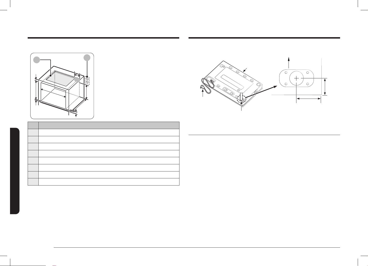
Utility locations and dimensions
Front of unit
Power cord 39
3
/8”
(100.0 cm) long
3
/8”-18 NPT male
gas inlet
* Gas inlet protrudes 1
9
/16” (4.0 cm)
from bottom.
Front of cooktop
Chassis
1
1
/4”
(3.2 cm)
1
15
/16”
(5.0 cm)
Gas supply requirements
Provide adequate gas supply
This cooktop is designed to operate at a pressure of 5 in (13 cm) of water column
on natural gas or 10 in (25 cm) of water column on LP gas (propane or butane).
Make sure you are supplying your cooktop with the type of gas for which it is
designed. Do not attempt to convert the appliance from the gas specied in this
manual to a different gas without consulting the gas supplier.
This cooktop is convertible for use on natural or propane gas. If you decide to use
this cooktop on LP gas, conversion must be made by a qualied LP installer before
attempting to operate the cooktop.
For proper operation, the pressure of natural gas supplied to the regulator must be
between 5 in and 13 in (13 cm and 33 cm) of water column.
For LP gas, the pressure supplied must be between 10 in and 13 in (25 cm and
33 cm) of water column.
When checking for proper operation of the regulator, the inlet pressure must be at
least 1 in (2.5 cm) greater than the operating (manifold) pressure as given.
Install_DTG36P875N_DG68-01286A-00_EN+MES+CFR.indb 12 2020-05-27 �� 11:00:33
Loading ...
Loading ...
Loading ...